EP3643141B1 - Mikrowellen-gargerät mit patchantenne - Google Patents
Mikrowellen-gargerät mit patchantenne Download PDFInfo
- Publication number
- EP3643141B1 EP3643141B1 EP18729965.6A EP18729965A EP3643141B1 EP 3643141 B1 EP3643141 B1 EP 3643141B1 EP 18729965 A EP18729965 A EP 18729965A EP 3643141 B1 EP3643141 B1 EP 3643141B1
- Authority
- EP
- European Patent Office
- Prior art keywords
- microwave
- cooking appliance
- cooking chamber
- light
- emission body
- Prior art date
- Legal status (The legal status is an assumption and is not a legal conclusion. Google has not performed a legal analysis and makes no representation as to the accuracy of the status listed.)
- Active
Links
Images


Classifications
-
- H—ELECTRICITY
- H05—ELECTRIC TECHNIQUES NOT OTHERWISE PROVIDED FOR
- H05B—ELECTRIC HEATING; ELECTRIC LIGHT SOURCES NOT OTHERWISE PROVIDED FOR; CIRCUIT ARRANGEMENTS FOR ELECTRIC LIGHT SOURCES, IN GENERAL
- H05B6/00—Heating by electric, magnetic or electromagnetic fields
- H05B6/64—Heating using microwaves
- H05B6/72—Radiators or antennas
-
- H—ELECTRICITY
- H05—ELECTRIC TECHNIQUES NOT OTHERWISE PROVIDED FOR
- H05B—ELECTRIC HEATING; ELECTRIC LIGHT SOURCES NOT OTHERWISE PROVIDED FOR; CIRCUIT ARRANGEMENTS FOR ELECTRIC LIGHT SOURCES, IN GENERAL
- H05B6/00—Heating by electric, magnetic or electromagnetic fields
- H05B6/64—Heating using microwaves
- H05B6/6444—Aspects relating to lighting devices in the microwave cavity
-
- H—ELECTRICITY
- H05—ELECTRIC TECHNIQUES NOT OTHERWISE PROVIDED FOR
- H05B—ELECTRIC HEATING; ELECTRIC LIGHT SOURCES NOT OTHERWISE PROVIDED FOR; CIRCUIT ARRANGEMENTS FOR ELECTRIC LIGHT SOURCES, IN GENERAL
- H05B6/00—Heating by electric, magnetic or electromagnetic fields
- H05B6/64—Heating using microwaves
- H05B6/70—Feed lines
Definitions
- the invention relates to a microwave cooking device, having a cooking space delimited by a cooking space wall and a microwave device for introducing microwaves into the cooking space, which has at least one patch antenna, the patch antenna having a flat base body and a flat radiating body which is spaced apart and which can be fed with microwave energy and the base body and the radiating body are electrically isolated from one another.
- the invention is particularly advantageously applicable to household appliances, in particular stand-alone microwave appliances or ovens with a microwave function.
- WO 2016/043731 A1 discloses a microwave cooking device having a cooking space which is arranged to receive a load, at least two patch antennas which are coupled to at least one microwave generator, and a control unit.
- Each of the at least two patch antennas is configured in such a way that it can emit microwaves into a predefined direct heating zone within the cooking chamber near the respective patch antenna.
- the control unit is configured to select energy levels for each of the at least two patch antennas as if the load were static and as if there was no interference between the at least two patch antennas. This has the disadvantage that the simple patch antennas used have only a small feed bandwidth.
- U.S. 5,558,800 discloses a microwave power radiator for microwave heating applications. It is disclosed that output matching networks, which are normally contained in a microwave power transistor package, as well as a transistor combination network for heating applications, for example in microwave ovens, are eliminated.
- the transistor dies of four microwave silicon bipolar transistors are directly connected to points of low impedance of a common patch antenna element, which is also referred to as an applicator, and are arranged in the wall of a cooking chamber instead of a magnetron.
- Each pair of power transistors are electrically spaced one-half wavelength apart and are disposed across the antenna.
- the transistors are paired with a phase difference operated from 200 °, so that mutually orthogonal longitudinal modes are excited in the antenna.
- the transistors are frequency modulated over their prescribed frequency band to eliminate standing waves in the load, ie, in the object or substance that is being heated or cooked.
- Either one or more patch antennas can be used and operated, for example at two different frequencies that are approved for heating applications, typically 915 MHz and 2450 MHz.
- the patch antenna used has only a small feed bandwidth.
- US 2016/066369 A1 combines a feed of microwave radiation via waveguides with a light source.
- a waveguide opening is separated from a cooking space by a cover, for example borosilicate glass.
- a lighting device Next to the waveguide, and thus outside the microwave field, there is a lighting device, the light source of which is also brought behind the cover through a passage opening and thus illuminates the cooking space through the glass. In this case, however, care must be taken to place the lighting device outside the waveguide cross-section so as not to expose it to excessive microwave radiation or so that the microwave radiation is not unfavorably diverted.
- the documents WO 2011/070765 A1 , DE 10 2015 109685 A1 and EP 2477455 A1 disclose further microwave cooking devices with patch antennas.
- the object is achieved by a microwave cooking device according to claim 1.
- This microwave cooking device has the advantage that the patch antenna has a particularly simple, robust and cost-effective structure and can also feed microwaves with a comparatively large bandwidth into the cooking space.
- the microwave cooking device can be a pure microwave device or a microwave combination device, for example a cooking device that is or has an oven with a microwave function.
- the microwave cooking appliance is in particular a household appliance.
- the microwave device can have a microwave generator (e.g. a magnetron) and at least one microwave line leading to the at least one patch antenna.
- a microwave generator e.g. a magnetron
- the (partial) area of the cooking space wall which forms the base body, is a flat partial area of the cooking space wall.
- the base body is electrically conductive and has a specified reference potential.
- the base body can in particular serve as a mass.
- the microwave radiation is emitted via the radiating body.
- the radiating body is also electrically conductive.
- a frequency of the microwaves can include, for example, 915 MHz or 2.45 GHz.
- a flat body can in particular be understood to mean a body which has a noticeable or non-negligible lateral extent (i.e., height and width) when viewed from above on the cooking chamber wall.
- the fact that the patch antenna has a planar base body and a planar radiating body which overlaps the base body at a spaced apart means consequently that a cavity is located between the base body and the radiating body.
- the radiating body is a plate-shaped radiating body.
- the radiating body can in particular be a planar radiating body.
- the radiating body can also be referred to as a patch or resonator.
- the radiating body has a rectangular shape when viewed from above, the corners to avoid excessive fields and the associated arcing can be rounded.
- any other surface shape is also conceivable, wherein the radiating body can have openings or incisions.
- the radiating body can therefore generally be a non-perforated or a perforated (for example slotted) body.
- the cooking chamber wall and the radiator are electrically conductive. They can be made of metal, in particular sheet metal.
- the cooking space wall and / or the radiating body can be coated.
- the wall of the cooking space can also be referred to as a muffle.
- the base body corresponds to a recess in the cooking space wall, the radiating body is inserted into the recess.
- the base body and the radiating body are electrically insulated from one another by a circumferential gap. In this way, a compact patch antenna that is particularly easy to manufacture is provided.
- the depression is an embossing or bulge.
- it can be a material recess or a separately produced and then inserted section of the cooking chamber wall.
- the gap is in particular a circumferential gap when viewed from above on the depression.
- the gap can in particular have a practically constant gap width.
- the gap is an air gap.
- the gap is closed or sealed by means of an electrically insulating closure material.
- the use of the closure material has the advantage that the gap is mechanically bridged and the radiating body can thereby be stably positioned and fastened.
- the cavity between the base body and the radiating body is more advantageously protected from contamination and / or other environmental influences and is also less thermally stressed.
- the closure material covers the gap and at least a partial surface of the radiating body, possibly also the cooking chamber wall adjoining the gap outside the patch antenna on the cooking chamber side.
- This can enable a particularly simple application of the sealing material, e.g. inexpensively with a general coating of the oven cavity.
- the surface of the radiator on the cooking space side can thus be protected and / or used functionally. Particularly easy cleaning is also made possible.
- a particularly simple adaptation of the optical appearance of the patch antenna to the rest of the cooking space wall is possible.
- closure material only covers the gap and the surface of the radiating body on the cooking space side in a layered manner.
- the surface of the radiator on the cooking space side can then be lowered according to the thickness of the sealing material there, so that the patch antenna is again flush with the surrounding wall or the patch antenna is flush with the cooking space wall or the surrounding wall.
- the closure material is glass or glass ceramic.
- the sealing material can withstand typical oven temperatures, e.g. up to 300 ° C. When used in a pyrolytic oven with microwave functionality, the sealing material can also withstand typical pyrolysis temperatures of 450 ° C. or more without damage.
- the volume or the cavity between the base body and the radiating body is filled with electrically insulating, in particular temperature-resistant, sealing material such as glass wool or ceramic foam in order to achieve better thermal insulation or electrical dielectric strength.
- the gap is closed by means of a translucent, electrically insulating closure material and the microwave device has at least one light source, the light of which can be coupled into the closure material from outside the cooking space.
- the patch antenna can also be used to illuminate the cooking space. The effect that light is directed is used or can be radiated diffusely into the cooking space if the sealing material is illuminated by at least one light source which can be positioned inside or outside the patch antenna.
- the at least one light source couples its light laterally into the closure material.
- the closure material can then act as a light guide and in particular decouple the light again over its entire length or its entire circumference.
- a large light-emitting surface can be provided for emitting light into the cooking space.
- the surface of the sealing material on the cooking space side can be structured accordingly, e.g. roughened.
- the light can be coupled in directly or directly into the sealing material located in the gap, in particular by means of a light source attached to the sealing material.
- the light is coupled in via an optical waveguide or via a waveguide or an air gap (“indirectly”) into the sealing material located in the gap.
- At least one light source is arranged in such a way that it emits its light into the cavity between the base body and the radiating body.
- the transparent sealing compound present in the gap then serves as a transmitted light element or window.
- the light source can for example be arranged in the area of the base body, e.g. protrude or radiate through an opening in the base body.
- the recess in the cooking space wall which provides the base body corresponds to a recess in a cooking space lighting. So it is possible that a recess or indentation provided for lighting purposes in the cooking chamber wall also accommodates the radiating body or the patch antenna, and the radiating body also seals this space against environmental influences. In this way it is possible to emit light from the antenna unit to an optically transparent walling of this room and in this way to radiate light into the cooking chamber.
- the inner surfaces of the patch antenna facing the cavity are designed to be reflective. This increases a coupling-out efficiency for light radiated into the cavity.
- a surface of the base body adjoining the cavity can be configured to be reflective for this purpose.
- the inner surface (s) can be designed to be diffusely reflective and / or specular.
- the microwave device has a microwave feed that is coupled to the radiating body.
- microwave energy can be fed to the radiating body.
- the coupling can be an inductive coupling, a shaft coupling and so on.
- a coupling position of the inner conductor on the radiating body can be selected in such a way that the most advantageous possible radiating characteristic results.
- the microwave device has a microwave feed that is capacitively coupled to the radiating body.
- the capacitive coupling of the antenna advantageously achieves a significantly larger bandwidth compared to a conventional patch antenna.
- the feed can thus take place over a larger frequency range with little loss.
- the structural design of the capacitive coupling is not restricted in principle.
- the microwave feed is a coaxial line, for example a coaxial cable.
- the inner conductor of the coaxial line is coupled to the radiating body in terms of high frequency technology.
- the outer conductor can be electrically connected to the cooking chamber wall or to another ground potential. It is a further development that the inner conductor is electrically insulated through the base body and passed through the cavity to the radiating body.
- the inner conductor is electrical from the radiator insulated, for example by an air gap or by an electrically insulating material or a dielectric.
- an inner conductor of the coaxial line is loosely inserted into a sleeve-like receiving area of the radiating body (i.e. not in contact with the radiating body) and an intermediate space between the inner conductor and the sleeve-like receiving area is filled with a dielectric.
- the sleeve-like receiving area is attached at least to the surface on the cavity side or the rear or underside of the radiating body. On the back of the radiating body there is therefore a sleeve-shaped geometry which, together with the inner conductor of the coaxial line and the dielectric in between, forms a cylinder capacitor.
- the cylinder capacitor can be carried out as far as the surface or front side on the cooking space side.
- the inner conductor can be terminated in the interior of the radiating body by the dielectric, in which case the front side of the radiating body then forms a continuous plane.
- any other suitable microwave line can also be used, e.g. a waveguide, a microstrip line, etc. However, these possibilities are not claimed.
- patch antennas are present on the cooking chamber wall, which are aligned rotated relative to one another.
- the rotation of the patch antennas results in the advantage that a polarization direction of the microwaves is also rotated and a transmission of microwaves between the patch antennas can thereby be reduced. It is an advantageous development for a particularly effective suppression of the microwave transmission between the patch antennas that the patch antennas are rotated by 90 ° with respect to one another.
- Fig.1 shows, as a sectional illustration in an oblique view, a detail from a cooking space wall 1 of a domestic cooking appliance H in the area of a patch antenna 2.
- the patch antenna 2 is constructed with mirror symmetry, in particular along the sectional plane.
- the cooking space wall 1 delimits a cooking space G.
- the patch antenna 2 has a flat base body 3 in the form of a partial area of the cooking space wall 1 on which a recess 4 is located.
- the base body 3 consequently corresponds to a region of the cooking space wall 1.
- the recess 4 is designed here as a recess produced by removing material.
- a flat bottom 5 of the recess 4 on the cooking space side is covered by a plate-like radiating body ("patch" 6).
- the patch 6 is inserted into the recess 4 in such a way that its upper side 7 facing the cooking space G is arranged practically flush with the cooking space wall 1.
- the base body 3 corresponds in particular to an area of the cooking space wall 1 below the flat base 5, possibly also below the side edges of the recess 4.
- the bottom 5 and the patch 6 are electrically conductive. For this purpose, they can have corresponding metallic areas, for example each have a metal sheet.
- the metal of bottom 5 and patch 6 can be the same or different. So the bottom 5 and the patch 6 can both have sheet steel or consist of sheet steel. Alternatively can the bottom have sheet steel or consist of sheet steel and the patch 6 have copper sheet or consist of copper sheet.
- the base 5 and the patch 6 are arranged parallel to one another.
- the recess 4 and the patch 6 form and delimit a cavity 8.
- the base 5 and the patch 6 have a rectangular basic shape in plan view, the corners of which can be rounded.
- the edge of the cooking space wall 1 delimiting the recess 4 and an edge of the patch 6 are separated from one another by a circumferential, rectangular annular gap 9.
- the annular gap 9 is filled with an electrically insulating closure material 10 in the form of glass or glass ceramic.
- the base body 3 and the patch 6 are therefore electrically insulated from one another, since the cavity 8 also has an electrically insulating effect.
- the cavity 8 can be filled with air or glass wool, etc. for this purpose.
- the patch 6 can be fed with microwave energy.
- An inner conductor 12 of the coaxial line 11 is guided through a bore 13 in the base body 3 and further through the cavity 8 to a rear side 14 of the patch 6.
- the inner conductor 12 is electrically insulated from the cooking chamber wall 1, for which purpose an intermediate space between the inner conductor 12 and the base body 3 is filled with a dielectric 15.
- the dielectric 15 also serves to mechanically fix the inner conductor 12.
- the inner conductor 12 is furthermore electrically insulated from the patch 6, so that a capacitive coupling for microwaves occurs between these components.
- the closure material 10 is translucent.
- the household appliance H has at least one light source, for example an LED 16, the light L of which can be coupled into the sealing material 10 from outside the cooking space G.
- the LED 16 can radiate its light L directly into the closure material 10, for example into a lateral edge.
- the shutter material 10 then acts as a light guide and distributes the light L around its periphery. The light L is then emitted into the cooking space G, possibly also partially into the cavity 8.
- the sealing material 10 thus serves to illuminate the cooking space.
- At least one light source for example an LED 17, can radiate its light directly into the cavity 8.
- the LED 17 can be arranged in the area of the bottom 5 of the recess 4.
- the closure material 10 then serves as a window for light to pass into the cooking space G.
- the inner surfaces of the patch antenna 2 facing the cavity 8 can be designed to be reflective, e.g. the surface of the recess 4, including the base 5, and / or the rear side 14 of the patch 6.
- patch antennas 2 are present in the cooking space wall 1, in particular in one side of the cooking space wall 1, these can be aligned rotated relative to one another in plan view.
- Fig. 2 shows as a sectional illustration in side view as a detail a first variant of a capacitive coupling of the inner conductor 12 and the patch 6 of the patch antenna 2.
- the patch 6 has a tubular or sleeve-like receiving area 18 protruding into the cavity 8 at the rear.
- the receiving area 18 is formed here continuously through the patch 6, that is, it opens into the cooking space G.
- the inner conductor 12 is loosely inserted into the receiving area 18.
- a tubular space 19 between the inner conductor 12 and the sleeve-like receiving area 18 is filled with a dielectric 20.
- the sleeve-like receiving area 18, together with the inner conductor 12 of the coaxial line and the interposed dielectric 20, in particular forms a cylinder capacitor.
- the cylinder capacitor is carried out here as far as the surface 7 of the patch 6 on the cooking space side.
- the dielectrics 15 and 20 can be the same or different.
- Fig. 3 shows a sectional view in side view of a second variant of a capacitive coupling of the inner conductor 12 and a patch 21 of a patch antenna 2.
- the patch 21 is designed similar to the patch 6, but now the sleeve-like receiving area 22 is not, but on the plate-shaped portion of the patch 21 connects.
- Receiving area 22 is thus closed off towards the front or towards the cooking space G.
- the front side 7 of the patch 21 facing the cooking space G forms a continuous plane.
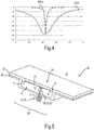
- Fig. 4 shows a frequency response FGE of the patch antenna 2 as a plot of a reflection factor
- the frequency response FGE is considerably broader than a frequency response FGH of a conventional patch antenna. Both frequency responses FGE and FGH have an extreme point at the known microwave frequency of 2.45 GHz.
- Fig. 5 shows a section from a cooking chamber wall 23 in the area of a patch antenna 24 as a sectional illustration in an oblique view.
- the patch antenna 24 has a similar basic structure to the patch antenna 2.
- a base body 25 the surface of which forms the recess 4 (possibly also only its bottom 5) of the cooking space wall 23, has now not been produced by removing material, but by embossing or the like.
- the sealing material 10 now also covers the patch 21 and the cooking space wall 23 outside the recess 4 in a layered manner. Overall, a layer of the sealing material 10 that is smooth towards the cooking space G is provided.
- the patch antenna 24 can also be designed to radiate light into the cooking space (not shown).
- a number can also include exactly the specified number as well as a customary tolerance range, as long as this is not explicitly excluded.
Landscapes
- Physics & Mathematics (AREA)
- Electromagnetism (AREA)
- Constitution Of High-Frequency Heating (AREA)
- Electric Ovens (AREA)
Description
- Die Erfindung betrifft ein Mikrowellen-Gargerät, aufweisend einen von einer Garraumwand begrenzten Garraum und eine Mikrowelleneinrichtung zum Einleiten von Mikrowellen in den Garraum, die mindestens eine Patchantenne aufweist, wobei die Patchantenne einen flächigen Grundkörper und einen den Grundkörper beabstandet überdeckenden, mit Mikrowellenenergie speisbaren flächigen Abstrahlkörper aufweist und der Grundkörper und der Abstrahlkörper gegeneinander elektrisch isoliert sind. Die Erfindung ist insbesondere vorteilhaft anwendbar auf Haushaltsgeräte, insbesondere eigenständige Mikrowellengeräte oder Backöfen mit Mikrowellenfunktion.
-
WO 2016/043731 A1 offenbart ein Mikrowellen-Gargerät, das einen Garraum aufweist, der dazu angeordnet ist, eine Last aufzunehmen, mindestens zwei Patchantennen, die mit mindestens einem Mikrowellengenerator gekoppelt sind, und eine Steuereinheit. Jede der mindestens zwei Patchantennen ist so konfiguriert, dass sie Mikrowellen in eine vordefinierte direkte Heizzone innerhalb des Garraums nahe der jeweiligen Patchantenne ausstrahlen kann. Die Steuereinheit ist so konfiguriert, dass sie Energieniveaus für jede der mindestens zwei Patchantennen auswählt, als ob die Last statisch wäre und als ob keine Interferenz zwischen den mindestens zwei Patchantennen auftritt. Hierbei tritt der Nachteil auf, dass die verwendeten einfachen Patchantennen eine nur geringe Bandbreite der Einspeisung aufweisen. -
US 5,558,800 offenbart einen Mikrowellen-Leistungsstrahler für Mikrowellen-Heizanwendungen. Dabei wird offenbart, dass Ausgangsanpassungsnetzwerke, die normalerweise in einem Mikrowellen-Leistungstransistorpaket enthalten sind, sowie ein Transistor-Kombinationsnetzwerk dafür für Heizanwendungen, z.B. in Mikrowellenöfen, eliminiert werden. In einer Variante sind die Transistor-Dies von vier Mikrowellen-Silizium-Bipolartransistoren direkt mit Punkten geringer Impedanz eines gemeinsamen Patchantennen-Elements, das auch als Applikator bezeichnet wird, verbunden und in der Wand eines Garraums anstelle eines Magnetrons angeordnet. Jedes Paar von Leistungstransistoren ist elektrisch mit einer halben Wellenlänge beabstandet und ist quer zueinander auf der Antenne angeordnet. Die Transistoren werden paarweise mit einer Phasendifferenz von 200° betrieben, so dass in der Antenne gegenseitig orthogonale Längsmodi angeregt werden. Darüber hinaus werden die Transistoren über ihr vorgeschriebenes Frequenzband frequenzmoduliert, um stehende Wellen in der Last, d.h., in dem Gegenstand oder der Substanz, die erwärmt oder gekocht wird, zu eliminieren. Entweder eine oder mehrere Patchantennen können verwendet und betrieben werden, z.B. mit zwei verschiedenen Frequenzen, die für Heizanwendungen zugelassen sind, typischerweise mit 915 MHz und 2450 MHz. Auch hier tritt der Nachteil auf, dass die verwendete Patchantenne eine nur geringe Bandbreite der Einspeisung aufweist. -
US 2016/066369 A1 kombiniert eine Einspeisung von Mikrowellenstrahlung über Hohlleiter mit einer Lichtquelle. Eine Hohlleiteröffnung ist dabei durch eine Abdeckung, z.B. Borosilikatglas, von einem Garraum abgetrennt. Neben dem Hohlleiter, und damit außerhalb des Mikrowellenfeldes, befindet sich eine Beleuchtungseinrichtung, deren Lichtquelle durch eine Durchgangsöffnung ebenfalls hinter die Abdeckung gebracht wird und so durch das Glas den Garraum beleuchtet. Hierbei muss jedoch darauf geachtet werden, die Beleuchtungseinrichtung außerhalb des Hohlleiterquerschnitts zu platzieren, um sie keiner zu hohen Mikrowellenstrahlung auszusetzen oder damit die Mikrowellenstrahlung nicht ungünstig umgeleitet wird. Die DokumentenWO 2011/070765 A1 ,DE 10 2015 109685 A1 undEP 2477455 A1 offenbaren weitere Mikrowellen-Gargeräte mit Patchantennen. - Es ist die Aufgabe der vorliegenden Erfindung, die Nachteile des Standes der Technik zumindest teilweise zu überwinden und insbesondere ein Mikrowellen-Gargerät bereitzustellen, das bei einem einfachen und kostengünstigen Aufbau Mikrowellen mit einer größeren Bandbreite in den Garraum einspeisen kann.
- Diese Aufgabe wird gemäß den Merkmalen des unabhängigen Anspruchs gelöst. Bevorzugte Ausführungsformen sind insbesondere den abhängigen Ansprüchen entnehmbar.
- Die Aufgabe wird gelöst durch ein Mikrowellen-Gargerät nach Anspruch 1.
- Dieses Mikrowellen-Gargerät weist den Vorteil auf, dass die Patchantenne einen besonders einfachen, robusten und kostengünstigen Aufbau aufweist und zudem Mikrowellen mit einer vergleichsweise großen Bandbreite in den Garraum einspeisen kann.
- Das Mikrowellen-Gargerät kann ein reines Mikrowellengerät oder ein Mikrowellen-Kombinationsgerät sein, z.B. ein Gargerät, das einen Backofen mit einer Mikrowellenfunktion ist oder aufweist. Das Mikrowellen-Gargerät ist insbesondere ein Haushaltsgerät.
- Die Mikrowelleneinrichtung kann einen Mikrowellenerzeuger (z.B. ein Magnetron) und mindestens eine zu der mindestens einen Patchantenne führende Mikrowellenleitung aufweisen.
- Es ist eine Weiterbildung, dass der (Teil-)Bereich der Garraumwand, welcher den Grundkörper bildet, ein ebener Teilbereich der Garraumwand ist. Der Grundkörper ist elektrisch leitfähig und liegt auf einem vorgegebenen Bezugspotenzial. Der Grundkörper kann insbesondere als Masse dienen.
- Die Abstrahlung der Mikrowellenstrahlung erfolgt über den Abstrahlkörper. Auch der Abstrahlkörper ist elektrisch leitfähig. Eine Frequenz der Mikrowellen kann z.B. 915 MHz oder 2,45 GHz umfassen.
- Unter einem flächigen Körper kann insbesondere ein Körper verstanden werden, der bei Draufsicht auf die Garraumwand eine merkliche bzw. nicht vernachlässigbare seitliche Ausdehnung (d.h., Höhe und Breite) aufweist. Dass die Patchantenne einen flächigen Grundkörper und einen den Grundkörper beabstandet überdeckenden flächigen Abstrahlkörper aufweist, umfasst folglich, dass sich zwischen dem Grundkörper und dem Abstrahlkörper ein Hohlraum befindet.
- Es ist eine Weiterbildung, dass der Abstrahlkörper ein plattenförmiger Abstrahlkörper ist. Der Abstrahlkörper kann insbesondere ein ebener Abstrahlkörper sein. Der Abstrahlkörper kann auch als Patch oder Resonator bezeichnet werden. Der Abstrahlkörper weist in einer besonders einfachen Ausführung eine in Draufsicht rechteckige Form auf, wobei die Ecken zur Vermeidung von Feldüberhöhungen und damit einhergehenden Funkenüberschlägen abgerundet sein können. Jedoch ist auch jede andere Flächenform denkbar, wobei der Abstrahlkörper Öffnungen oder Einschnitte aufweisen kann. Der Abstrahlkörper kann also allgemein ein nicht-durchbrochener oder ein durchbrochener (z.B. geschlitzter) Körper sein.
- Die Garraumwand und der Abstrahlkörper sind elektrisch leitfähig. Sie können aus Metall bestehen, insbesondere aus Metallblech. Die Garraumwand und/oder der Abstrahlkörper können beschichtet sein. Die Garraumwand kann auch als Muffel bezeichnet werden. Es ist eine Ausgestaltung, dass der Grundkörper einer Vertiefung der Garraumwand entspricht, der Abstrahlkörper in die Vertiefung eingesetzt ist. Erfindungsgemäß sind der Grundkörper und der Abstrahlkörper durch einen umlaufenden Spalt gegeneinander elektrisch isoliert. So wird eine besonders einfach herstellbare und kompakte Patchantenne bereitgestellt.
- Es ist eine Weiterbildung, dass die Vertiefung eine Prägung oder Ausbuchtung ist. Sie kann alternativ eine Materialaussparung oder ein separat hergestelltes und dann eingesetztes Teilstück der Garraumwand sein.
- Der Spalt ist insbesondere ein bei Draufsicht auf die Vertiefung umlaufender Spalt. Der Spalt kann insbesondere eine praktisch konstante Spaltbreite aufweisen.
- Es ist eine nicht beanspruchte Weiterbildung, dass der Spalt ein Luftspalt ist. Erfindungsgemäß ist der Spalt mittels eines elektrisch isolierenden Verschlussmaterials verschlossen oder abgedichtet. Die Verwendung des Verschlussmaterials ergibt den Vorteil, dass der Spalt mechanisch gebrückt wird und der Abstrahlkörper dadurch stabil positioniert und befestigt werden kann. Darüber hinaus ist so der Hohlraum zwischen Grundkörper und Abstrahlkörper vorteilhafter vor Verschmutzung und/oder anderen Umwelteinflüssen geschützt und wird zudem thermisch weniger beansprucht.
- Es ist eine Weiterbildung, dass nur der Spalt mittels eines elektrisch isolierenden Verschlussmaterials verschlossen oder abgedichtet ist, jedoch nicht die garraumseitige Oberfläche des Abstrahlkörpers.
- Es ist eine alternative Ausgestaltung, dass das Verschlussmaterial den Spalt und zumindest eine Teilfläche des Abstrahlkörpers, ggf. auch die an den Spalt außerhalb der Patchantenne angrenzende Garraumwand garraumseitig überdeckt. Dies kann eine besonders einfache Aufbringung des Verschlussmaterials ermöglichen, z.B. kostengünstig mit einer allgemeinen Garraumbeschichtung. Zudem kann so die garraumseitige Oberfläche des Abstrahlkörpers geschützt und/oder funktional genutzt werden. Auch wird eine besonders leichte Reinigung ermöglicht. Darüber hinaus wird eine besonders einfache Anpassung der optischen Erscheinung der Patchantenne an die restliche Garraumwand möglich.
- Es ist eine Weiterbildung davon, dass das Verschlussmaterial nur den Spalt und die garraumseitige Oberfläche des Abstrahlkörpers schichtartig bedeckt. Dann kann die garraumseitige Oberfläche des Abstrahlkörpers entsprechend der dortigen Dicke des Verschlussmaterials abgesenkt werden, so dass die Patchantenne wieder flächenbündig zur umgebenden Wand angeordnet ist bzw. sich die Patchantenne flächenbündig in die Garraumwand oder die umgebende Wand einfügt.
- Es ist eine weitere Ausgestaltung, dass das Verschlussmaterial Glas oder Glaskeramik ist. Dies ergibt den Vorteil, dass das Verschlussmaterial mechanisch, chemisch und thermisch besonders widerstandsfähig ist. Insbesondere kann das Verschlussmaterial dann typische Backofentemperaturen aushalten, z.B. bis 300°C. Auch kann das Verschlussmaterial bei Einsatz in einem pyrolysefähigen Backofen mit Mikrowellenfunktionalität typische Pyrolysetemperaturen von 450°C oder mehr ohne Schaden aushalten.
- Es ist eine Weiterbildung, dass das Volumen bzw. der Hohlraum zwischen dem Grundkörper und dem Abstrahlkörper mit elektrisch isolierendem, insbesondere temperaturbeständigem, Dichtungsmaterial wie Glaswolle oder Keramikschaum gefüllt ist, um eine bessere thermische Isolation oder elektrische Durchschlagfestigkeit zu erreichen.
- Es ist noch eine weitere Ausgestaltung, dass der Spalt mittels eines lichtdurchlässigen elektrisch isolierenden Verschlussmaterials verschlossen ist und das Mikrowellengerät mindestens eine Lichtquelle aufweist, deren Licht von außerhalb des Garraums in das Verschlussmaterial einkoppelbar ist. Dies ergibt den Vorteil, dass die Patchantenne auch als Garraumbeleuchtung dienen kann. Dabei wird der Effekt ausgenutzt, dass Licht gerichtet oder diffus in den Garraum abgestrahlt werden kann, wenn das Verschlussmaterial durch mindestens eine Lichtquelle, die innerhalb oder außerhalb der Patchantenne positioniert sein kann, angestrahlt wird.
- Es ist eine Weiterbildung, dass die mindestens eine Lichtquelle ihr Licht seitlich in das Verschlussmaterial einkoppelt. Das Verschlussmaterial kann dann als ein Lichtleiter wirken und das Licht insbesondere über seine gesamte Länge oder seinen gesamten Umfang wieder auskoppeln. So kann eine große Lichtabstrahlfläche zur Lichtabgabe in den Garraum bereitgestellt werden. Um eine besonders gleichmäßige Lichtabgabe in den Garraum zu erreichen, kann die garraumseitige Oberfläche des Verschlussmaterials entsprechend strukturiert, z.B. aufgeraut, sein.
- Die Lichteinkopplung kann unmittelbar oder direkt in das in dem Spalt befindliche Verschlussmaterial erfolgen, insbesondere durch eine an dem Verschlussmaterial angebrachte Lichtquelle.
- Es ist eine Weiterbildung, dass die Lichteinkopplung über einen Lichtwellenleiter oder über einen Hohlleiter oder eine Luftstrecke ("indirekt") in das in dem Spalt befindliche Verschlussmaterial erfolgt. In anderen Worten befindet sich zwischen dem in dem Spalt befindlichen Verschlussmaterial und der Lichtquelle mindestens ein Lichtwellenleiter (Lichtleitfaser oder Hohlleiter) oder eine Luftstrecke. Dies ergibt den Vorteil, dass eine Positionierung der Lichtquelle in größerer Entfernung zur Patchantenne möglich ist. Die Lichtquelle kann dadurch leichter thermisch von dem Garraum isoliert werden und wird keiner Mikrowellenstrahlung ausgesetzt.
- Es ist eine allgemeine Weiterbildung, dass mindestens eine Lichtquelle so angeordnet ist, dass sie ihr Licht in den Hohlraum zwischen Grundkörper und Abstrahlkörper emittiert. Die in dem Spalt vorhandene lichtdurchlässige Verschlussmasse dient dann als ein Durchlichtelement oder Fenster. Die Lichtquelle kann beispielsweise im Bereich des Grundkörpers angeordnet sein, z.B. durch eine Öffnung in dem Grundkörper ragen oder einstrahlen.
- Es ist auch eine Ausgestaltung, dass die den Grundkörper bereitstellende Vertiefung der Garraumwand einer Vertiefung einer Garraumbeleuchtung entspricht. So ist es möglich, dass eine für Beleuchtungszwecke vorgesehene Vertiefung oder Einbuchtung in der Garraumwand auch den Abstrahlkörper bzw. die Patchantenne aufnimmt, und der Abstrahlkörper auch die Abdichtung dieses Raumes gegen Umwelteinflüsse bewirkt. Auf diese Weise ist es möglich, Licht aus der Antenneneinheit an eine optisch durchlässige Bewandung dieses Raumes abzugeben und auf diese Weise Licht in den Garraum abzustrahlen.
- Es ist außerdem eine Ausgestaltung, dass dem Hohlraum zugewandte Innenflächen der Patchantenne reflektierend ausgebildet sind. Dies erhöht eine Auskopplungseffizienz für in den Hohlraum gestrahltes Licht. Insbesondere eine an den Hohlraum grenzende Oberfläche des Grundkörpers kann dazu reflektierend ausgestaltet sein. Die Innenfläche(n) können diffus reflektierend und/oder spiegelnd ausgebildet sein.
- Es ist eine Weiterbildung, dass die Mikrowelleneinrichtung eine Mikrowellenzuführung aufweist, die mit dem Abstrahlkörper gekoppelt ist. So kann Mikrowellenenergie zu dem Abstrahlkörper geführt werden. Die Kopplung kann eine induktive Kopplung, eine Wellenkopplung usw. sein. Allgemein kann eine Ankopplungsposition des Innenleiters an dem Abstrahlkörper so gewählt werden, dass sich eine möglichst vorteilhafte Abstrahlungscharakteristik ergibt.
- Es ist ferner eine Ausgestaltung, dass die Mikrowelleneinrichtung eine Mikrowellenzuführung aufweist, die mit dem Abstrahlkörper kapazitiv gekoppelt ist. Insbesondere durch die kapazitive Ankopplung der Antenne wird vorteilhafterweise eine deutlich größere Bandbreite gegenüber einer herkömmlichen Patchantenne erzielt. Die Einspeisung kann damit über einen größeren Frequenzbereich verlustarm erfolgen. Dabei ist die konstruktive Ausgestaltung der kapazitiven Kopplung grundsätzlich nicht beschränkt.
- Erfindungsgemäß ist die Mikrowellenzuführung eine Koaxialleitung, z.B. ein Koaxialkabel. Der Innenleiter der Koaxialleitung ist hochfrequenztechnisch mit dem Abstrahlkörper gekoppelt, Der Außenleiter kann elektrisch an die Garraumwand oder an ein anderes Massepotenzial angeschlossen sein. Es ist eine Weiterbildung, dass der Innenleiter elektrisch isoliert durch den Grundkörper und weiter durch den Hohlraum zu dem Abstrahlkörper geführt ist. Der Innenleiter ist elektrisch von dem Abstrahlkörper isoliert, z.B. durch einen Luftspalt oder durch ein elektrisch isolierendes Material bzw. ein Dielektrikum.
- Erfindungsgemäß ist ein Innenleiter der Koaxialleitung in einen hülsenartigen Aufnahmebereich des Abstrahlkörpers lose (d.h., den Abstrahlkörper nicht kontaktierend) eingeführt und ein Zwischenraum zwischen dem Innenleiter und dem hülsenartigen Aufnahmebereich ist mit einem Dielektrikum gefüllt. Dies ergibt den Vorteil einer einfachen und präzisen Positionierung und Fixierung des Innenleiters sowie eine einfache Herstellung der kapazitiven Kopplung. Der hülsenartige Aufnahmebereich setzt zumindest an der hohlraumseitigen Oberfläche bzw. Rück- oder Unterseite des Abstrahlkörpers an. An der Rückseite des Abstrahlkörpers befindet sich also eine hülsenförmige Geometrie, die zusammen mit dem Innenleiter der Koaxialleitung und dem dazwischenliegenden Dielektrikum einen Zylinderkondensator bildet. Der Zylinderkondensator kann bis zu der garraumseitigen Oberfläche oder Vorderseite durchgeführt sein. Alternativ kann der Innenleiter im Inneren des Abstrahlkörpers durch das Dielektrikum abgeschlossen sein, wobei dann die Vorderseite des Abstrahlkörpers eine durchgehende Ebene bildet. Anstelle einer Koaxialleitung kann auch jede andere geeignete Mikrowellenleitung verwendet werden, z.B. ein Hohlleiter, eine Mikrostreifenleitung usw. Diese Möglichkeiten werden jedoch nicht beansprucht.
- Es ist zudem eine Ausgestaltung, dass an der Garraumwand mehrere Patchantennen vorhanden sind, die gegeneinander verdreht ausgerichtet sind. Die Drehung der Patchantennen ergibt den Vorteil, dass so auch eine Polarisationsrichtung der Mikrowellen verdreht wird und dadurch eine Übertragung von Mikrowellen zwischen den Patchantennen verringerbar ist. Es ist eine für eine besonders effektive Unterdrückung der Mikrowellenübertragung zwischen den Patchantennen vorteilhafte Weiterbildung, dass die Patchantennen um 90° gegeneinander verdreht sind.
- Die oben beschriebenen Eigenschaften, Merkmale und Vorteile dieser Erfindung sowie die Art und Weise, wie diese erreicht werden, werden klarer und deutlicher verständlich im Zusammenhang mit der folgenden schematischen Beschreibung eines Ausführungsbeispiels, das im Zusammenhang mit den Zeichnungen näher erläutert wird.
- Fig.1
- zeigt als Schnittdarstellung in Schrägansicht einen Ausschnitt aus einer Garraumwand im Bereich einer Patchantenne gemäß einem ersten Ausführungsbeispiel;
- Fig.2
- zeigt als Schnittdarstellung in Seitenansicht eine erste Variante einer kapazitiven Kopplung eines Innenleiters und eines Abstrahlkörpers der Patchantenne;
- Fig.3
- zeigt als Schnittdarstellung in Seitenansicht eine zweite Variante einer kapazitiven Kopplung eines Innenleiters und eines Abstrahlkörpers der Patchantenne;
- Fig.4
- zeigt einen Frequenzgang der Patchantenne; und
- Fig.5
- zeigt als Schnittdarstellung in Schrägansicht einen Ausschnitt aus einer Garraumwand im Bereich einer Patchantenne gemäß einem zweiten Ausführungsbeispiel.
-
Fig.1 zeigt als Schnittdarstellung in Schrägansicht einen Ausschnitt aus einer Garraumwand 1 eines Haushaltsgargeräts H im Bereich einer Patchantenne 2. Die Patchantenne 2 ist insbesondere entlang der Schnittebene spiegelsymmetrisch aufgebaut. - Die Garraumwand 1 begrenzt einen Garraum G. Die Patchantenne 2 weist einen flächigen Grundkörper 3 in Form eines Teilbereichs der Garraumwand 1 auf, an dem sich eine Vertiefung 4 befindet. Der Grundkörper 3 entspricht folglich einem Bereich der Garraumwand 1. Die Vertiefung 4 ist hier als eine materialabtragend hergestellte Vertiefung ausgebildet.
- Ein garraumseitiger ebener Boden 5 der Vertiefung 4 wird von einem plattenartigen Abstrahlkörper ("Patch" 6) überdeckt. Das Patch 6 ist so in die Vertiefung 4 eingesetzt, dass es mit seiner dem Garraum G zugewandten Oberseite 7 praktisch flächenbündig zu der Garraumwand 1 angeordnet ist. Der Grundkörper 3 entspricht insbesondere einem Bereich der Garraumwand 1 unterhalb des ebenen Bodens 5, ggf. auch unterhalb der Seitenränder der Vertiefung 4.
- Der Boden 5 und das Patch 6 sind elektrisch leitfähig. Sie können dazu entsprechende metallische Bereiche aufweisen, z.B. jeweils ein Metallblech aufweisen. Das Metall von Boden 5 und Patch 6 kann gleich oder unterschiedlich sein. So können der Boden 5 und das Patch 6 beide Stahlblech aufweisen oder aus Stahlblech bestehen. Alternativ kann der Boden Stahlblech aufweisen oder aus Stahlblech bestehen und das Patch 6 Kupferblech aufweisen oder aus Kupferblech bestehen.
- Der Boden 5 und das Patch 6 sind parallel zueinander angeordnet, Die Vertiefung 4 und das Patch 6 bilden und begrenzen einen Hohlraum 8. Der Boden 5 und das Patch 6 weisen eine in Draufsicht rechteckige Grundform auf, deren Ecken abgerundet sein können.
- Der die Vertiefung 4 begrenzende Rand der Garraumwand 1 und ein Rand des Patchs 6 sind durch einen umlaufenden, rechteckigen Ringspalt 9 voneinander getrennt. Der Ringspalt 9 ist mit einem elektrisch isolierenden Verschlussmaterial 10 in Form von Glas oder Glaskeramik gefüllt. Der Grundkörper 3 und das Patch 6 sind also gegeneinander elektrisch isoliert, da auch der Hohlraum 8 elektrisch isolierend wirkt. Der Hohlraum 8 kann dazu mit Luft oder Glaswolle usw. gefüllt sein.
- Das Patch 6 ist mit Mikrowellenenergie speisbar. Dazu wird eine Koaxialleitung 11 verwendet, die an einen Mikrowellenerzeuger (o. Abb.) angekoppelt ist. Ein Innenleiter 12 der Koaxialleitung 11 wird durch eine Bohrung 13 in dem Grundkörper 3 und weiter durch den Hohlraum 8 bis zu einer Rückseite 14 des Patchs 6 geführt. Der Innenleiter 12 ist gegen die Garraumwand 1 elektrisch isoliert, wozu hier ein Zwischenraum zwischen Innenleiter 12 und Grundkörper 3 mit einen Dielektrikum 15 gefüllt ist. Das Dielektrikum 15 dient auch einer mechanischen Fixierung des Innenleiters 12.
- Der Innenleiter 12 ist ferner gegen das Patch 6 elektrisch isoliert, so dass eine kapazitive Kopplung für Mikrowellen zwischen diesen Komponenten zustande kommt.
- In einer Variante ist das Verschlussmaterial 10 lichtdurchlässig. Das Haushaltsgerät H weist mindestens eine Lichtquelle, z.B. eine LED 16, auf, deren Licht L von außerhalb des Garraums G in das Verschlussmaterial 10 einkoppelbar ist. Die LED 16 kann ihr Licht L direkt in das Verschlussmaterial 10 einstrahlen, z.B. in einen seitlichen Rand. Das Verschlussmaterial 10 wirkt dann als ein Lichtleiter und verteilt das Licht L um seinen Umfang. Das Licht L wird dann in den Garraum G abgestrahlt, ggf. anteilig auch in den Hohlraum 8. Das Verschlussmaterial 10 dient somit zur Garraumbeleuchtung.
- Alternativ oder zusätzlich kann mindestens eine Lichtquelle, z.B. eine LED 17, ihr Licht unmittelbar in den Hohlraum 8 einstrahlen. Dazu kann die LED 17 im Bereich des Bodens 5 der Vertiefung 4 angeordnet sein. Das Verschlussmaterial 10 dient dann als ein Fenster für einen Lichtdurchtritt in den Garraum G.
- Zur Erhöhung einer Lichtausbeute können die dem Hohlraum 8 zugewandten Innenflächen der Patchantenne 2 reflektierend ausgebildet sein, z.B. die Oberfläche der Vertiefung 4, einschließlich des Bodens 5, und/oder die Rückseite 14 des Patchs 6.
- Falls in der Garraumwand 1, insbesondere in einer Seite der Garraumwand 1, mehrere Patchantennen 2 vorhanden sind, können diese in Draufsicht gegeneinander verdreht ausgerichtet sein.
-
Fig.2 zeigt als Schnittdarstellung in Seitenansicht als Ausschnitt eine erste Variante einer kapazitiven Kopplung des Innenleiters 12 und des Patchs 6 der Patchantenne 2. - Das Patch 6 weist dazu einen rückwärtig in den Hohlraum 8 ragenden rohr- oder hülsenartigen Aufnahmebereich 18 auf. Der Aufnahmebereich 18 ist hier durchgängig durch das Patch 6 ausgebildet, mündet also in den Garraum G. In den Aufnahmebereich 18 ist der Innenleiter 12 lose eingeführt. Ein rohrförmiger Zwischenraum 19 zwischen dem Innenleiter 12 und dem hülsenartigen Aufnahmebereich 18 ist mit einem Dielektrikum 20 gefüllt. Dies gibt den Vorteil einer einfachen und präzisen Positionierung und Fixierung des Innenleiters 12 sowie eine einfache Herstellung der kapazitiven Kopplung. Der hülsenartigen Aufnahmebereich 18 bildet zusammen mit dem Innenleiter 12 der Koaxialleitung und dem dazwischenliegenden Dielektrikum 20 insbesondere einen Zylinderkondensator. Der Zylinderkondensator ist hier bis zur der garraumseitigen Oberfläche 7 des Patchs 6 durchgeführt.
- Die Dielektrika 15 und 20 können gleich oder unterschiedlich sein.
-
Fig.3 zeigt als Schnittdarstellung in Seitenansicht eine zweite Variante einer kapazitiven Kopplung des Innenleiters 12 und eines Patchs 21 einer Patchantenne 2. Das Patch 21 ist ähnlich zu dem Patch 6 ausgebildet, wobei aber nun der hülsenartige Aufnahmebereich 22 nicht ist, sondern an dem plattenförmigen Teilbereich des Patchs 21 anschließt. Der - Aufnahmebereich 22 ist somit nach vorne bzw. zum Garraum G hin abgeschlossen. Die dem Garraum G zugewandte Vorderseite 7 des Patchs 21 bildet eine durchgehende Ebene.
-
Fig.4 zeigt einen Frequenzgang FGE der Patchantenne 2 als Auftragung eines Reflexionsfaktors |11| in dB auf der y-Achse gegen eine Frequenz in GHz auf der x-Achse. Der Frequenzgang FGE ist erheblich breitbandiger als ein Frequenzgang FGH einer herkömmlichen Patchantenne. Beide Frequenzgänge FGE und FGH weisen eine Extremstelle bei der bekannten Mikrowellenfrequenz von 2,45 GHz auf. -
Fig.5 zeigt als Schnittdarstellung in Schrägansicht einen Ausschnitt aus einer Garraumwand 23 im Bereich einer Patchantenne 24. Die Patchantenne 24 weist einen ähnlichen Grundaufbau wie die Patchantenne 2 auf. Jedoch ist ein Grundkörper 25, dessen Oberfläche die Vertiefung 4 (ggf. auch nur dessen Boden 5) der Garraumwand 23 bildet, nun nicht durch einen Materialabtrag, sondern durch eine Prägung o.ä. hergestellt worden ist. - Zudem überdeckt das Verschlussmaterial 10 schichtartig nun auch das Patch 21 und die Garraumwand 23 außerhalb der Vertiefung 4. Insgesamt wird eine zum Garraum G hin glatte Schicht des Verschlussmaterials 10 bereitgestellt.
- Auch die Patchantenne 24 kann zur Lichtabstrahlung in den Garraum ausgebildet sein (o. Abb.).
- Selbstverständlich ist die vorliegende Erfindung nicht auf das gezeigte Ausführungsbeispiel beschränkt.
- Allgemein kann unter "ein", "eine" usw. eine Einzahl oder eine Mehrzahl verstanden werden, insbesondere im Sinne von "mindestens ein" oder "ein oder mehrere" usw., solange dies nicht explizit ausgeschlossen ist, z.B. durch den Ausdruck "genau ein" usw.
- Auch kann eine Zahlenangabe genau die angegebene Zahl als auch einen üblichen Toleranzbereich umfassen, solange dies nicht explizit ausgeschlossen ist.
-
- 1
- Garraumwand
- 2
- Patchantenne
- 3
- Grundkörper
- 4
- Vertiefung
- 5
- Boden
- 6
- Patch
- 7
- Oberseite
- 8
- Hohlraum
- 9
- Ringspalt
- 10
- Verschlussmaterial
- 11
- Koaxialleitung
- 12
- Innenleiter
- 13
- Bohrung
- 14
- Rückseite des Patchs
- 15
- Dielektrikum
- 16
- LED
- 17
- LED
- 18
- Aufnahmebereich
- 19
- Zwischenraum
- 20
- Dielektrikum
- 21
- Patch
- 22
- Aufnahmebereich
- 23
- Garraumwand
- 24
- Patchantenne
- 25
- Grundkörper
- FGE
- Frequenzgang
- FGH
- Frequenzgang
- G
- Garraum
- H
- Haushaltsgargerät
- L
- Licht
Claims (13)
- Mikrowellen-Gargerät (H), aufweisend- einen von einer Garraumwand (1; 23) begrenzten Garraum (G) und- eine Mikrowelleneinrichtung zum Einleiten von Mikrowellen in den Garraum (G), die mindestens eine Patchantenne (2; 24) aufweist, wobei- die Patchantenne (2; 24) einen flächigen Grundkörper (3; 25) und einen den Grundkörper (3; 25) beabstandet überdeckenden, mit Mikrowellenenergie speisbaren flächigen Abstrahlkörper (6; 21) aufweist,- der Grundkörper (3; 25) und der Abstrahlkörper (6; 21) gegeneinander elektrisch isoliert sind und- der Grundkörper (3; 25) einer Vertiefung (4) der Garraumwand (1) entspricht,- der Abstrahlkörper (6; 21) in die Vertiefung (4) eingesetzt ist und- die Mikrowellenzüführung eine Koaxialleitung (11) ist, dadurch gekennzeichnet, dass- der Grundkörper (3; 25) und der Abstrahlkörper (6; 21) durch einen seitlich um den Abstrahlkörper (6; 21) umlaufenden Spalt (9) gegeneinander elektrisch isoliert sind, dass- der Spalt (9) mittels eines elektrisch isolierenden Verschlussmaterials (10) verschlossen ist, und dass- ein Innenleiter (12) der Koaxialleitung (11) in einen hülsenartigen Aufnahmebereich (18; 22) des Abstrahlkörpers (6; 21) lose eingeführt ist und ein Zwischenraum (19) zwischen dem Innenleiter (12) und dem hülsenartigen Aufnahmebereich (18; 22) mit einem Dielektrikum (20) gefüllt ist.
- Mikrowellen-Gargerät (H) nach Anspruch 1, dadurch gekennzeichnet, dass das Verschlussmaterial (10) den Abstrahlkörper (21) und den Spalt (9) garraumseitig überdeckt.
- Mikrowellen-Gargerät (H) nach einem der vorhergehenden Ansprüche, dadurch gekennzeichnet, dass das Verschlussmaterial (10) Glas oder Glaskeramik ist.
- Mikrowellen-Gargerät (H) nach einem der vorhergehenden Ansprüche, dadurch gekennzeichnet, dass- der Spalt (9) mittels eines lichtdurchlässigen elektrisch isolierenden Verschlussmaterials (10) verschlossen ist und- das Mikrowellen-Gargerät (H) mindestens eine Lichtquelle (16, 17) aufweist, deren Licht (L) von außerhalb des Garraums (G) in das Verschlussmaterial (10) einkoppelbar ist.
- Mikrowellen-Gargerät (H) nach Anspruch 4, dadurch gekennzeichnet, dass die Vertiefung (4) der Garraumwand (1; 23) einer Vertiefung einer Garraumbeleuchtung entspricht.
- Mikrowellen-Gargerät (H) nach einem der Ansprüche 4 bis 5, dadurch gekennzeichnet, dass Innenflächen (5, 14) der Patchantenne (2; 24) lichtreflektierend ausgebildet sind.
- Mikrowellen-Gargerät (H) nach einem der Ansprüche 4 bis 6, dadurch gekennzeichnet, dass die mindestens eine Lichtquelle (16, 17) ihr Licht seitlich in das Verschlussmaterial (10) einkoppelt.
- Mikrowellen-Gargerät (H) nach einem der Ansprüche 4 bis 6, dadurch gekennzeichnet, dass die mindestens eine Lichtquelle (16, 17) so angeordnet ist, dass sie ihr Licht in einen Hohlraum (8) zwischen Grundkörper (3; 25) und Abstrahlkörper (6; 21) emittiert.
- Mikrowellen-Gargerät (H) nach einem der vorhergehenden Ansprüche, dadurch gekennzeichnet, dass der Abstrahlkörper (6; 21) an seiner dem Garraum (G) zugewandten Seite (7) flächenbündig zu der Garraumwand (1; 23) angeordnet ist.
- Mikrowellen-Gargerät (H) nach einem der vorhergehenden Ansprüche, dadurch gekennzeichnet, dass die Mikrowelleneinrichtung eine Mikrowellenzuführung aufweist, die mit dem Abstrahlkörper kapazitiv gekoppelt ist.
- Mikrowellen-Gargerät (H) nach einem der vorhergehenden Ansprüche, dadurch gekennzeichnet, dass der Abstrahlkörper (6; 21) ein plattenförmiger, insbesondere ebener, Abstrahlkörper ist.
- Mikrowellen-Gargerät (H) nach einem der vorhergehenden Ansprüche, dadurch gekennzeichnet, dass ein Hohlraum zwischen dem Grundkörper (3; 25) und dem Abstrahlkörper (6; 21) mit elektrisch isolierendem, temperaturbeständigem Dichtungsmaterial gefüllt ist.
- Mikrowellen-Gargerät (H) nach einem der vorhergehenden Ansprüche, dadurch gekennzeichnet, dass an der Garraumwand (1; 23), insbesondere an einer Seite der Garraumwand (1; 23), mehrere Patchantennen (2; 24) vorhanden sind, die gegeneinander verdreht ausgerichtet sind.
Applications Claiming Priority (2)
| Application Number | Priority Date | Filing Date | Title |
|---|---|---|---|
| DE102017210275.6A DE102017210275A1 (de) | 2017-06-20 | 2017-06-20 | Mikrowellen-Gargerät mit Patchantenne |
| PCT/EP2018/065161 WO2018234064A1 (de) | 2017-06-20 | 2018-06-08 | Mikrowellen-gargerät mit patchantenne |
Publications (2)
| Publication Number | Publication Date |
|---|---|
| EP3643141A1 EP3643141A1 (de) | 2020-04-29 |
| EP3643141B1 true EP3643141B1 (de) | 2021-12-15 |
Family
ID=62563162
Family Applications (1)
| Application Number | Title | Priority Date | Filing Date |
|---|---|---|---|
| EP18729965.6A Active EP3643141B1 (de) | 2017-06-20 | 2018-06-08 | Mikrowellen-gargerät mit patchantenne |
Country Status (5)
| Country | Link |
|---|---|
| US (1) | US11533792B2 (de) |
| EP (1) | EP3643141B1 (de) |
| CN (1) | CN110741731B (de) |
| DE (1) | DE102017210275A1 (de) |
| WO (1) | WO2018234064A1 (de) |
Families Citing this family (2)
| Publication number | Priority date | Publication date | Assignee | Title |
|---|---|---|---|---|
| US12225654B2 (en) * | 2018-09-14 | 2025-02-11 | Panasonic Intellectual Property Management Co., Ltd. | Microwave heating device |
| KR102759206B1 (ko) * | 2020-04-07 | 2025-01-24 | 엘지전자 주식회사 | 작동 신뢰성이 향상된 전송 커넥터 |
Family Cites Families (10)
| Publication number | Priority date | Publication date | Assignee | Title |
|---|---|---|---|---|
| US4335290A (en) | 1978-01-05 | 1982-06-15 | Raytheon Company | Microwave oven blower radiator |
| US5558800A (en) | 1995-06-19 | 1996-09-24 | Northrop Grumman | Microwave power radiator for microwave heating applications |
| KR19990026281A (ko) | 1997-09-23 | 1999-04-15 | 윤종용 | 전자렌지의 마이크로파 분산장치 |
| RU2012108636A (ru) | 2009-09-07 | 2013-10-20 | Панасоник Корпорэйшн | Микроволновое нагревательное устройство |
| WO2011070765A1 (ja) * | 2009-12-09 | 2011-06-16 | パナソニック株式会社 | マイクロ波加熱装置及びその設計支援方法 |
| US9024831B2 (en) * | 2011-05-26 | 2015-05-05 | Wang-Electro-Opto Corporation | Miniaturized ultra-wideband multifunction antenna via multi-mode traveling-waves (TW) |
| EP2793726B1 (de) * | 2011-12-21 | 2020-09-30 | Neuwave Medical, Inc. | Energieversorgungssysteme |
| DE102014112522A1 (de) | 2014-09-01 | 2016-03-03 | Miele & Cie. Kg | Gargerät |
| US11191133B2 (en) | 2014-09-17 | 2021-11-30 | Whirlpool Corporation | Direct heating through patch antennas |
| DE102015109685B4 (de) * | 2015-06-17 | 2024-05-23 | Topinox Sarl | Gargerät mit einer Mikrowellenquelle sowie Antenne für ein Gargerät |
-
2017
- 2017-06-20 DE DE102017210275.6A patent/DE102017210275A1/de not_active Withdrawn
-
2018
- 2018-06-08 CN CN201880041060.4A patent/CN110741731B/zh active Active
- 2018-06-08 EP EP18729965.6A patent/EP3643141B1/de active Active
- 2018-06-08 US US16/490,615 patent/US11533792B2/en active Active
- 2018-06-08 WO PCT/EP2018/065161 patent/WO2018234064A1/de not_active Ceased
Also Published As
| Publication number | Publication date |
|---|---|
| US11533792B2 (en) | 2022-12-20 |
| WO2018234064A1 (de) | 2018-12-27 |
| US20200015327A1 (en) | 2020-01-09 |
| CN110741731A (zh) | 2020-01-31 |
| DE102017210275A1 (de) | 2018-12-20 |
| CN110741731B (zh) | 2022-03-04 |
| EP3643141A1 (de) | 2020-04-29 |
Similar Documents
| Publication | Publication Date | Title |
|---|---|---|
| EP3338515B1 (de) | Kerntemperaturfühler, mikrowellen-gargerät und system | |
| EP3029770B1 (de) | Planarantenne mit abdeckung | |
| DE2504860B2 (de) | Mikrowellen-Heizvorrichtung | |
| DE2650681B2 (de) | Mikrowellenofen | |
| DE3310703A1 (de) | Mikrowellenkochgeraet | |
| DE2715655A1 (de) | Mikrowellenenergiezufuehrung fuer kombinierte kochherde | |
| DE69934279T2 (de) | Mikrowellenofen versehen mit Halogenlampen | |
| DE3117709A1 (de) | Mikrowellenzufuehrungseinrichtung fuer mikrowellenoefen | |
| EP3643141A1 (de) | Mikrowellen-gargerät mit patchantenne | |
| EP1063678A2 (de) | Vorrichtung zur Erzeugung eines Plasmas in einer Kammer durch Mikrowellenanregung | |
| DE2362734A1 (de) | Magnetron | |
| EP2187700B1 (de) | Gargerät und Verfahren zum Einspeisen von Mikrowellen in einen Innenraum eines Gargeräts | |
| DE3029648A1 (de) | Mikrowellenheizvorrichtung | |
| DE10054513A1 (de) | Dielektrische Heizvorrichtung | |
| DE102015109685B4 (de) | Gargerät mit einer Mikrowellenquelle sowie Antenne für ein Gargerät | |
| DE2424778A1 (de) | Wellenleiterfilter, insbesondere fuer mikrowellengeraete | |
| EP2187699B1 (de) | Gargerät und Verfahren zum Einspeisen von Mikrowellen in einen Innenraum eines Gargeräts | |
| EP2187702A1 (de) | Gargerät mit Mikrowellenheizung | |
| EP0049817A1 (de) | Mikrowellenheizgerät mit Abdichtung an der Türe zur Verhinderung des Austrittes von Mikrowellen | |
| EP2187703B1 (de) | Gargerät mit Mikrowelleneinspeisung | |
| EP3536125B1 (de) | Haushalts-gargerät | |
| CH640626A5 (en) | Microwave oven | |
| EP3815464A1 (de) | Haushalts-mikrowellengerät und verfahren zum herstellen einer mikrowellenleitung | |
| BE1030944B1 (de) | Hochfrequenz-Haushaltsgerät, vorzugsweise Hochfrequenz-Gargerät | |
| DE102019128042A1 (de) | Gargerät, Mikrowellenbaugruppe sowie Verfahren zum Betreiben eines Gargeräts |
Legal Events
| Date | Code | Title | Description |
|---|---|---|---|
| STAA | Information on the status of an ep patent application or granted ep patent |
Free format text: STATUS: UNKNOWN |
|
| STAA | Information on the status of an ep patent application or granted ep patent |
Free format text: STATUS: THE INTERNATIONAL PUBLICATION HAS BEEN MADE |
|
| PUAI | Public reference made under article 153(3) epc to a published international application that has entered the european phase |
Free format text: ORIGINAL CODE: 0009012 |
|
| STAA | Information on the status of an ep patent application or granted ep patent |
Free format text: STATUS: REQUEST FOR EXAMINATION WAS MADE |
|
| 17P | Request for examination filed |
Effective date: 20200120 |
|
| AK | Designated contracting states |
Kind code of ref document: A1 Designated state(s): AL AT BE BG CH CY CZ DE DK EE ES FI FR GB GR HR HU IE IS IT LI LT LU LV MC MK MT NL NO PL PT RO RS SE SI SK SM TR |
|
| AX | Request for extension of the european patent |
Extension state: BA ME |
|
| DAV | Request for validation of the european patent (deleted) | ||
| DAX | Request for extension of the european patent (deleted) | ||
| GRAP | Despatch of communication of intention to grant a patent |
Free format text: ORIGINAL CODE: EPIDOSNIGR1 |
|
| STAA | Information on the status of an ep patent application or granted ep patent |
Free format text: STATUS: GRANT OF PATENT IS INTENDED |
|
| INTG | Intention to grant announced |
Effective date: 20210812 |
|
| GRAS | Grant fee paid |
Free format text: ORIGINAL CODE: EPIDOSNIGR3 |
|
| GRAA | (expected) grant |
Free format text: ORIGINAL CODE: 0009210 |
|
| STAA | Information on the status of an ep patent application or granted ep patent |
Free format text: STATUS: THE PATENT HAS BEEN GRANTED |
|
| AK | Designated contracting states |
Kind code of ref document: B1 Designated state(s): AL AT BE BG CH CY CZ DE DK EE ES FI FR GB GR HR HU IE IS IT LI LT LU LV MC MK MT NL NO PL PT RO RS SE SI SK SM TR |
|
| REG | Reference to a national code |
Ref country code: GB Ref legal event code: FG4D Free format text: NOT ENGLISH Ref country code: CH Ref legal event code: EP |
|
| REG | Reference to a national code |
Ref country code: DE Ref legal event code: R096 Ref document number: 502018008218 Country of ref document: DE |
|
| REG | Reference to a national code |
Ref country code: IE Ref legal event code: FG4D Free format text: LANGUAGE OF EP DOCUMENT: GERMAN |
|
| REG | Reference to a national code |
Ref country code: AT Ref legal event code: REF Ref document number: 1456454 Country of ref document: AT Kind code of ref document: T Effective date: 20220115 |
|
| REG | Reference to a national code |
Ref country code: LT Ref legal event code: MG9D |
|
| REG | Reference to a national code |
Ref country code: NL Ref legal event code: MP Effective date: 20211215 |
|
| PG25 | Lapsed in a contracting state [announced via postgrant information from national office to epo] |
Ref country code: RS Free format text: LAPSE BECAUSE OF FAILURE TO SUBMIT A TRANSLATION OF THE DESCRIPTION OR TO PAY THE FEE WITHIN THE PRESCRIBED TIME-LIMIT Effective date: 20211215 Ref country code: LT Free format text: LAPSE BECAUSE OF FAILURE TO SUBMIT A TRANSLATION OF THE DESCRIPTION OR TO PAY THE FEE WITHIN THE PRESCRIBED TIME-LIMIT Effective date: 20211215 Ref country code: FI Free format text: LAPSE BECAUSE OF FAILURE TO SUBMIT A TRANSLATION OF THE DESCRIPTION OR TO PAY THE FEE WITHIN THE PRESCRIBED TIME-LIMIT Effective date: 20211215 Ref country code: BG Free format text: LAPSE BECAUSE OF FAILURE TO SUBMIT A TRANSLATION OF THE DESCRIPTION OR TO PAY THE FEE WITHIN THE PRESCRIBED TIME-LIMIT Effective date: 20220315 |
|
| PG25 | Lapsed in a contracting state [announced via postgrant information from national office to epo] |
Ref country code: SE Free format text: LAPSE BECAUSE OF FAILURE TO SUBMIT A TRANSLATION OF THE DESCRIPTION OR TO PAY THE FEE WITHIN THE PRESCRIBED TIME-LIMIT Effective date: 20211215 Ref country code: NO Free format text: LAPSE BECAUSE OF FAILURE TO SUBMIT A TRANSLATION OF THE DESCRIPTION OR TO PAY THE FEE WITHIN THE PRESCRIBED TIME-LIMIT Effective date: 20220315 Ref country code: LV Free format text: LAPSE BECAUSE OF FAILURE TO SUBMIT A TRANSLATION OF THE DESCRIPTION OR TO PAY THE FEE WITHIN THE PRESCRIBED TIME-LIMIT Effective date: 20211215 Ref country code: HR Free format text: LAPSE BECAUSE OF FAILURE TO SUBMIT A TRANSLATION OF THE DESCRIPTION OR TO PAY THE FEE WITHIN THE PRESCRIBED TIME-LIMIT Effective date: 20211215 Ref country code: GR Free format text: LAPSE BECAUSE OF FAILURE TO SUBMIT A TRANSLATION OF THE DESCRIPTION OR TO PAY THE FEE WITHIN THE PRESCRIBED TIME-LIMIT Effective date: 20220316 |
|
| PG25 | Lapsed in a contracting state [announced via postgrant information from national office to epo] |
Ref country code: NL Free format text: LAPSE BECAUSE OF FAILURE TO SUBMIT A TRANSLATION OF THE DESCRIPTION OR TO PAY THE FEE WITHIN THE PRESCRIBED TIME-LIMIT Effective date: 20211215 |
|
| PG25 | Lapsed in a contracting state [announced via postgrant information from national office to epo] |
Ref country code: SM Free format text: LAPSE BECAUSE OF FAILURE TO SUBMIT A TRANSLATION OF THE DESCRIPTION OR TO PAY THE FEE WITHIN THE PRESCRIBED TIME-LIMIT Effective date: 20211215 Ref country code: SK Free format text: LAPSE BECAUSE OF FAILURE TO SUBMIT A TRANSLATION OF THE DESCRIPTION OR TO PAY THE FEE WITHIN THE PRESCRIBED TIME-LIMIT Effective date: 20211215 Ref country code: RO Free format text: LAPSE BECAUSE OF FAILURE TO SUBMIT A TRANSLATION OF THE DESCRIPTION OR TO PAY THE FEE WITHIN THE PRESCRIBED TIME-LIMIT Effective date: 20211215 Ref country code: PT Free format text: LAPSE BECAUSE OF FAILURE TO SUBMIT A TRANSLATION OF THE DESCRIPTION OR TO PAY THE FEE WITHIN THE PRESCRIBED TIME-LIMIT Effective date: 20220418 Ref country code: ES Free format text: LAPSE BECAUSE OF FAILURE TO SUBMIT A TRANSLATION OF THE DESCRIPTION OR TO PAY THE FEE WITHIN THE PRESCRIBED TIME-LIMIT Effective date: 20211215 Ref country code: EE Free format text: LAPSE BECAUSE OF FAILURE TO SUBMIT A TRANSLATION OF THE DESCRIPTION OR TO PAY THE FEE WITHIN THE PRESCRIBED TIME-LIMIT Effective date: 20211215 Ref country code: CZ Free format text: LAPSE BECAUSE OF FAILURE TO SUBMIT A TRANSLATION OF THE DESCRIPTION OR TO PAY THE FEE WITHIN THE PRESCRIBED TIME-LIMIT Effective date: 20211215 |
|
| PG25 | Lapsed in a contracting state [announced via postgrant information from national office to epo] |
Ref country code: PL Free format text: LAPSE BECAUSE OF FAILURE TO SUBMIT A TRANSLATION OF THE DESCRIPTION OR TO PAY THE FEE WITHIN THE PRESCRIBED TIME-LIMIT Effective date: 20211215 |
|
| REG | Reference to a national code |
Ref country code: DE Ref legal event code: R097 Ref document number: 502018008218 Country of ref document: DE |
|
| PG25 | Lapsed in a contracting state [announced via postgrant information from national office to epo] |
Ref country code: IS Free format text: LAPSE BECAUSE OF FAILURE TO SUBMIT A TRANSLATION OF THE DESCRIPTION OR TO PAY THE FEE WITHIN THE PRESCRIBED TIME-LIMIT Effective date: 20220415 |
|
| PLBE | No opposition filed within time limit |
Free format text: ORIGINAL CODE: 0009261 |
|
| STAA | Information on the status of an ep patent application or granted ep patent |
Free format text: STATUS: NO OPPOSITION FILED WITHIN TIME LIMIT |
|
| PG25 | Lapsed in a contracting state [announced via postgrant information from national office to epo] |
Ref country code: DK Free format text: LAPSE BECAUSE OF FAILURE TO SUBMIT A TRANSLATION OF THE DESCRIPTION OR TO PAY THE FEE WITHIN THE PRESCRIBED TIME-LIMIT Effective date: 20211215 Ref country code: AL Free format text: LAPSE BECAUSE OF FAILURE TO SUBMIT A TRANSLATION OF THE DESCRIPTION OR TO PAY THE FEE WITHIN THE PRESCRIBED TIME-LIMIT Effective date: 20211215 |
|
| 26N | No opposition filed |
Effective date: 20220916 |
|
| PG25 | Lapsed in a contracting state [announced via postgrant information from national office to epo] |
Ref country code: SI Free format text: LAPSE BECAUSE OF FAILURE TO SUBMIT A TRANSLATION OF THE DESCRIPTION OR TO PAY THE FEE WITHIN THE PRESCRIBED TIME-LIMIT Effective date: 20211215 |
|
| PG25 | Lapsed in a contracting state [announced via postgrant information from national office to epo] |
Ref country code: MC Free format text: LAPSE BECAUSE OF FAILURE TO SUBMIT A TRANSLATION OF THE DESCRIPTION OR TO PAY THE FEE WITHIN THE PRESCRIBED TIME-LIMIT Effective date: 20211215 |
|
| REG | Reference to a national code |
Ref country code: CH Ref legal event code: PL |
|
| REG | Reference to a national code |
Ref country code: BE Ref legal event code: MM Effective date: 20220630 |
|
| PG25 | Lapsed in a contracting state [announced via postgrant information from national office to epo] |
Ref country code: LU Free format text: LAPSE BECAUSE OF NON-PAYMENT OF DUE FEES Effective date: 20220608 Ref country code: LI Free format text: LAPSE BECAUSE OF NON-PAYMENT OF DUE FEES Effective date: 20220630 Ref country code: IE Free format text: LAPSE BECAUSE OF NON-PAYMENT OF DUE FEES Effective date: 20220608 Ref country code: FR Free format text: LAPSE BECAUSE OF NON-PAYMENT OF DUE FEES Effective date: 20220630 Ref country code: CH Free format text: LAPSE BECAUSE OF NON-PAYMENT OF DUE FEES Effective date: 20220630 |
|
| PG25 | Lapsed in a contracting state [announced via postgrant information from national office to epo] |
Ref country code: IT Free format text: LAPSE BECAUSE OF FAILURE TO SUBMIT A TRANSLATION OF THE DESCRIPTION OR TO PAY THE FEE WITHIN THE PRESCRIBED TIME-LIMIT Effective date: 20211215 Ref country code: BE Free format text: LAPSE BECAUSE OF NON-PAYMENT OF DUE FEES Effective date: 20220630 |
|
| PG25 | Lapsed in a contracting state [announced via postgrant information from national office to epo] |
Ref country code: MK Free format text: LAPSE BECAUSE OF FAILURE TO SUBMIT A TRANSLATION OF THE DESCRIPTION OR TO PAY THE FEE WITHIN THE PRESCRIBED TIME-LIMIT Effective date: 20211215 Ref country code: CY Free format text: LAPSE BECAUSE OF FAILURE TO SUBMIT A TRANSLATION OF THE DESCRIPTION OR TO PAY THE FEE WITHIN THE PRESCRIBED TIME-LIMIT Effective date: 20211215 |
|
| PG25 | Lapsed in a contracting state [announced via postgrant information from national office to epo] |
Ref country code: HU Free format text: LAPSE BECAUSE OF FAILURE TO SUBMIT A TRANSLATION OF THE DESCRIPTION OR TO PAY THE FEE WITHIN THE PRESCRIBED TIME-LIMIT; INVALID AB INITIO Effective date: 20180608 |
|
| REG | Reference to a national code |
Ref country code: AT Ref legal event code: MM01 Ref document number: 1456454 Country of ref document: AT Kind code of ref document: T Effective date: 20230608 |
|
| PG25 | Lapsed in a contracting state [announced via postgrant information from national office to epo] |
Ref country code: MT Free format text: LAPSE BECAUSE OF FAILURE TO SUBMIT A TRANSLATION OF THE DESCRIPTION OR TO PAY THE FEE WITHIN THE PRESCRIBED TIME-LIMIT Effective date: 20211215 |
|
| PG25 | Lapsed in a contracting state [announced via postgrant information from national office to epo] |
Ref country code: AT Free format text: LAPSE BECAUSE OF NON-PAYMENT OF DUE FEES Effective date: 20230608 |
|
| PG25 | Lapsed in a contracting state [announced via postgrant information from national office to epo] |
Ref country code: AT Free format text: LAPSE BECAUSE OF NON-PAYMENT OF DUE FEES Effective date: 20230608 |
|
| PGFP | Annual fee paid to national office [announced via postgrant information from national office to epo] |
Ref country code: DE Payment date: 20250630 Year of fee payment: 8 |
|
| PGFP | Annual fee paid to national office [announced via postgrant information from national office to epo] |
Ref country code: GB Payment date: 20250620 Year of fee payment: 8 |
|
| PG25 | Lapsed in a contracting state [announced via postgrant information from national office to epo] |
Ref country code: TR Free format text: LAPSE BECAUSE OF FAILURE TO SUBMIT A TRANSLATION OF THE DESCRIPTION OR TO PAY THE FEE WITHIN THE PRESCRIBED TIME-LIMIT Effective date: 20211215 |
|
| PGFP | Annual fee paid to national office [announced via postgrant information from national office to epo] |
Ref country code: AT Payment date: 20260410 Year of fee payment: 5 |