EP3640916A1 - Processing unit and processing method for collision warning system, collision warning system, and motorcycle - Google Patents
Processing unit and processing method for collision warning system, collision warning system, and motorcycle Download PDFInfo
- Publication number
- EP3640916A1 EP3640916A1 EP18729197.6A EP18729197A EP3640916A1 EP 3640916 A1 EP3640916 A1 EP 3640916A1 EP 18729197 A EP18729197 A EP 18729197A EP 3640916 A1 EP3640916 A1 EP 3640916A1
- Authority
- EP
- European Patent Office
- Prior art keywords
- warning
- output
- motorcycle
- collision
- bank angle
- Prior art date
- Legal status (The legal status is an assumption and is not a legal conclusion. Google has not performed a legal analysis and makes no representation as to the accuracy of the status listed.)
- Ceased
Links
Images

Classifications
-
- G—PHYSICS
- G08—SIGNALLING
- G08G—TRAFFIC CONTROL SYSTEMS
- G08G1/00—Traffic control systems for road vehicles
- G08G1/16—Anti-collision systems
- G08G1/166—Anti-collision systems for active traffic, e.g. moving vehicles, pedestrians, bikes
-
- B—PERFORMING OPERATIONS; TRANSPORTING
- B60—VEHICLES IN GENERAL
- B60W—CONJOINT CONTROL OF VEHICLE SUB-UNITS OF DIFFERENT TYPE OR DIFFERENT FUNCTION; CONTROL SYSTEMS SPECIALLY ADAPTED FOR HYBRID VEHICLES; ROAD VEHICLE DRIVE CONTROL SYSTEMS FOR PURPOSES NOT RELATED TO THE CONTROL OF A PARTICULAR SUB-UNIT
- B60W30/00—Purposes of road vehicle drive control systems not related to the control of a particular sub-unit, e.g. of systems using conjoint control of vehicle sub-units
- B60W30/08—Active safety systems predicting or avoiding probable or impending collision or attempting to minimise its consequences
- B60W30/095—Predicting travel path or likelihood of collision
-
- B—PERFORMING OPERATIONS; TRANSPORTING
- B60—VEHICLES IN GENERAL
- B60W—CONJOINT CONTROL OF VEHICLE SUB-UNITS OF DIFFERENT TYPE OR DIFFERENT FUNCTION; CONTROL SYSTEMS SPECIALLY ADAPTED FOR HYBRID VEHICLES; ROAD VEHICLE DRIVE CONTROL SYSTEMS FOR PURPOSES NOT RELATED TO THE CONTROL OF A PARTICULAR SUB-UNIT
- B60W50/00—Details of control systems for road vehicle drive control not related to the control of a particular sub-unit, e.g. process diagnostic or vehicle driver interfaces
- B60W50/08—Interaction between the driver and the control system
- B60W50/14—Means for informing the driver, warning the driver or prompting a driver intervention
- B60W50/16—Tactile feedback to the driver, e.g. vibration or force feedback to the driver on the steering wheel or the accelerator pedal
-
- G—PHYSICS
- G01—MEASURING; TESTING
- G01S—RADIO DIRECTION-FINDING; RADIO NAVIGATION; DETERMINING DISTANCE OR VELOCITY BY USE OF RADIO WAVES; LOCATING OR PRESENCE-DETECTING BY USE OF THE REFLECTION OR RERADIATION OF RADIO WAVES; ANALOGOUS ARRANGEMENTS USING OTHER WAVES
- G01S13/00—Systems using the reflection or reradiation of radio waves, e.g. radar systems; Analogous systems using reflection or reradiation of waves whose nature or wavelength is irrelevant or unspecified
- G01S13/86—Combinations of radar systems with non-radar systems, e.g. sonar, direction finder
-
- G—PHYSICS
- G01—MEASURING; TESTING
- G01S—RADIO DIRECTION-FINDING; RADIO NAVIGATION; DETERMINING DISTANCE OR VELOCITY BY USE OF RADIO WAVES; LOCATING OR PRESENCE-DETECTING BY USE OF THE REFLECTION OR RERADIATION OF RADIO WAVES; ANALOGOUS ARRANGEMENTS USING OTHER WAVES
- G01S13/00—Systems using the reflection or reradiation of radio waves, e.g. radar systems; Analogous systems using reflection or reradiation of waves whose nature or wavelength is irrelevant or unspecified
- G01S13/88—Radar or analogous systems specially adapted for specific applications
- G01S13/93—Radar or analogous systems specially adapted for specific applications for anti-collision purposes
- G01S13/931—Radar or analogous systems specially adapted for specific applications for anti-collision purposes of land vehicles
-
- G—PHYSICS
- G01—MEASURING; TESTING
- G01S—RADIO DIRECTION-FINDING; RADIO NAVIGATION; DETERMINING DISTANCE OR VELOCITY BY USE OF RADIO WAVES; LOCATING OR PRESENCE-DETECTING BY USE OF THE REFLECTION OR RERADIATION OF RADIO WAVES; ANALOGOUS ARRANGEMENTS USING OTHER WAVES
- G01S15/00—Systems using the reflection or reradiation of acoustic waves, e.g. sonar systems
- G01S15/88—Sonar systems specially adapted for specific applications
- G01S15/93—Sonar systems specially adapted for specific applications for anti-collision purposes
- G01S15/931—Sonar systems specially adapted for specific applications for anti-collision purposes of land vehicles
-
- G—PHYSICS
- G01—MEASURING; TESTING
- G01S—RADIO DIRECTION-FINDING; RADIO NAVIGATION; DETERMINING DISTANCE OR VELOCITY BY USE OF RADIO WAVES; LOCATING OR PRESENCE-DETECTING BY USE OF THE REFLECTION OR RERADIATION OF RADIO WAVES; ANALOGOUS ARRANGEMENTS USING OTHER WAVES
- G01S17/00—Systems using the reflection or reradiation of electromagnetic waves other than radio waves, e.g. lidar systems
- G01S17/88—Lidar systems specially adapted for specific applications
- G01S17/93—Lidar systems specially adapted for specific applications for anti-collision purposes
- G01S17/931—Lidar systems specially adapted for specific applications for anti-collision purposes of land vehicles
-
- B—PERFORMING OPERATIONS; TRANSPORTING
- B60—VEHICLES IN GENERAL
- B60W—CONJOINT CONTROL OF VEHICLE SUB-UNITS OF DIFFERENT TYPE OR DIFFERENT FUNCTION; CONTROL SYSTEMS SPECIALLY ADAPTED FOR HYBRID VEHICLES; ROAD VEHICLE DRIVE CONTROL SYSTEMS FOR PURPOSES NOT RELATED TO THE CONTROL OF A PARTICULAR SUB-UNIT
- B60W50/00—Details of control systems for road vehicle drive control not related to the control of a particular sub-unit, e.g. process diagnostic or vehicle driver interfaces
- B60W50/08—Interaction between the driver and the control system
- B60W50/14—Means for informing the driver, warning the driver or prompting a driver intervention
- B60W2050/143—Alarm means
-
- B—PERFORMING OPERATIONS; TRANSPORTING
- B60—VEHICLES IN GENERAL
- B60W—CONJOINT CONTROL OF VEHICLE SUB-UNITS OF DIFFERENT TYPE OR DIFFERENT FUNCTION; CONTROL SYSTEMS SPECIALLY ADAPTED FOR HYBRID VEHICLES; ROAD VEHICLE DRIVE CONTROL SYSTEMS FOR PURPOSES NOT RELATED TO THE CONTROL OF A PARTICULAR SUB-UNIT
- B60W2300/00—Indexing codes relating to the type of vehicle
- B60W2300/36—Cycles; Motorcycles; Scooters
-
- B—PERFORMING OPERATIONS; TRANSPORTING
- B60—VEHICLES IN GENERAL
- B60W—CONJOINT CONTROL OF VEHICLE SUB-UNITS OF DIFFERENT TYPE OR DIFFERENT FUNCTION; CONTROL SYSTEMS SPECIALLY ADAPTED FOR HYBRID VEHICLES; ROAD VEHICLE DRIVE CONTROL SYSTEMS FOR PURPOSES NOT RELATED TO THE CONTROL OF A PARTICULAR SUB-UNIT
- B60W2520/00—Input parameters relating to overall vehicle dynamics
- B60W2520/18—Roll
-
- B—PERFORMING OPERATIONS; TRANSPORTING
- B60—VEHICLES IN GENERAL
- B60W—CONJOINT CONTROL OF VEHICLE SUB-UNITS OF DIFFERENT TYPE OR DIFFERENT FUNCTION; CONTROL SYSTEMS SPECIALLY ADAPTED FOR HYBRID VEHICLES; ROAD VEHICLE DRIVE CONTROL SYSTEMS FOR PURPOSES NOT RELATED TO THE CONTROL OF A PARTICULAR SUB-UNIT
- B60W2554/00—Input parameters relating to objects
-
- B—PERFORMING OPERATIONS; TRANSPORTING
- B60—VEHICLES IN GENERAL
- B60Y—INDEXING SCHEME RELATING TO ASPECTS CROSS-CUTTING VEHICLE TECHNOLOGY
- B60Y2200/00—Type of vehicle
- B60Y2200/10—Road Vehicles
- B60Y2200/12—Motorcycles, Trikes; Quads; Scooters
-
- G—PHYSICS
- G01—MEASURING; TESTING
- G01S—RADIO DIRECTION-FINDING; RADIO NAVIGATION; DETERMINING DISTANCE OR VELOCITY BY USE OF RADIO WAVES; LOCATING OR PRESENCE-DETECTING BY USE OF THE REFLECTION OR RERADIATION OF RADIO WAVES; ANALOGOUS ARRANGEMENTS USING OTHER WAVES
- G01S13/00—Systems using the reflection or reradiation of radio waves, e.g. radar systems; Analogous systems using reflection or reradiation of waves whose nature or wavelength is irrelevant or unspecified
- G01S13/88—Radar or analogous systems specially adapted for specific applications
- G01S13/93—Radar or analogous systems specially adapted for specific applications for anti-collision purposes
- G01S13/931—Radar or analogous systems specially adapted for specific applications for anti-collision purposes of land vehicles
- G01S2013/9323—Alternative operation using light waves
-
- G—PHYSICS
- G01—MEASURING; TESTING
- G01S—RADIO DIRECTION-FINDING; RADIO NAVIGATION; DETERMINING DISTANCE OR VELOCITY BY USE OF RADIO WAVES; LOCATING OR PRESENCE-DETECTING BY USE OF THE REFLECTION OR RERADIATION OF RADIO WAVES; ANALOGOUS ARRANGEMENTS USING OTHER WAVES
- G01S13/00—Systems using the reflection or reradiation of radio waves, e.g. radar systems; Analogous systems using reflection or reradiation of waves whose nature or wavelength is irrelevant or unspecified
- G01S13/88—Radar or analogous systems specially adapted for specific applications
- G01S13/93—Radar or analogous systems specially adapted for specific applications for anti-collision purposes
- G01S13/931—Radar or analogous systems specially adapted for specific applications for anti-collision purposes of land vehicles
- G01S2013/9324—Alternative operation using ultrasonic waves
-
- G—PHYSICS
- G01—MEASURING; TESTING
- G01S—RADIO DIRECTION-FINDING; RADIO NAVIGATION; DETERMINING DISTANCE OR VELOCITY BY USE OF RADIO WAVES; LOCATING OR PRESENCE-DETECTING BY USE OF THE REFLECTION OR RERADIATION OF RADIO WAVES; ANALOGOUS ARRANGEMENTS USING OTHER WAVES
- G01S13/00—Systems using the reflection or reradiation of radio waves, e.g. radar systems; Analogous systems using reflection or reradiation of waves whose nature or wavelength is irrelevant or unspecified
- G01S13/88—Radar or analogous systems specially adapted for specific applications
- G01S13/93—Radar or analogous systems specially adapted for specific applications for anti-collision purposes
- G01S13/931—Radar or analogous systems specially adapted for specific applications for anti-collision purposes of land vehicles
- G01S2013/9327—Sensor installation details
- G01S2013/93271—Sensor installation details in the front of the vehicles
Definitions
- a collision warning system that recognizes a possibility of a collision occurred to a traveling motorcycle and warns a rider has been known.
- the collision warning system acquires environment information that corresponds to output of an environment detector provided in the motorcycle and makes a warning device output a warning when determining that there is the possibility of the collision on the basis of the environment information.
- the rider's operation is assisted by the warning that is output by the warning device (for example, see PTL 1).
- a motorcycle according to the invention includes the above collision warning system.
- the warning output by the warning device is changed in accordance with the posture information related to the bank angle of the motorcycle. Therefore, in a state where the motorcycle turns, that is, in a state where the large bank angle is generated in the motorcycle and a vehicle body becomes unstable, the warning device outputs the appropriate warning, and thus the rider's safety can be improved.
- a description will hereinafter be made on a case where a possibility of a collision ahead of the motorcycle is recognized by using an environment detector that detects the front of the motorcycle.
- a possibility of a collision in another direction (a lateral direction, a rear direction, or the like) of the motorcycle may be recognized by using an environment detector that detects the other direction (the lateral direction, the rear direction, or the like) of the motorcycle.
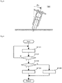
- Fig. 1 is a view of a state where the collision warning system according to the first embodiment of the invention is mounted on a motorcycle.
- Fig. 2 is a system configuration diagram of the collision warning system according to the first embodiment of the invention.
- Fig. 3 is a view illustrating a definition of a bank angle of the motorcycle.
- a collision warning system 1 is mounted on a motorcycle 100.
- the collision warning system 1 at least includes an environment detector 11 that detects the front of the motorcycle 100, an inertial measurement unit (IMU) 12 that detects inertia generated in the motorcycle 100, a processing unit (an ECU) 20, and a warning device 30.
- IMU inertial measurement unit
- ECU processing unit
- warning device 30 a warning device
- the collision warning system 1 plays a role of recognizing a possibility of a collision ahead of the traveling motorcycle 100 by using the environment detector 11 and a role of warning a rider by using the warning device 30.
- the processing unit 20 acquires output of the environment detector 11 and output of the inertial measurement unit 12, and outputs a control command to the warning device 30.
- the processing unit 20 also receives output of various detectors (not depicted) used to acquire travel state information of the motorcycle 100, the rider's operation state information, and the like, for example.
- Each device of the collision warning system 1 may exclusively be used in the collision warning system 1 or may also be used in another system.
- the environment detector 11 is a radar, a Lidar, an ultrasonic sensor, a camera, or the like, for example, and continuously detects a peripheral object (s) within a detection range during travel of the motorcycle 100.
- the inertial measurement unit 12 includes a three-axis gyroscope sensor and a three-directional acceleration sensor, for example, and outputs the detected inertia to the processing unit 20.
- the inertial measurement unit 12 may detect another physical quantity that can substantially be converted to the inertia generated in the motorcycle 100.
- the inertial measurement unit 12 may be another detector that can acquire posture information related to a bank angle ⁇ L of the motorcycle 100.
- the processing unit 20 includes an acquisition section 21, a determination section 22, and a control section 23.
- the sections of the processing unit 20 may collectively be provided in a single casing or may separately be provided in multiple casings.
- the processing unit 20 may partially or entirely be constructed of a microcomputer, a microprocessor unit, or the like, may be constructed of a member in which firmware and the like can be updated, or may be a program module or the like that is executed by a command from a CPU or the like, for example.
- the acquisition section 21 receives the output of the environment detector 11 and acquires environment information that corresponds to the output. Then, the determination section 22 determines whether there is a possibility that the motorcycle 100 collides by using a known method. More specifically, the determination section 22 processes the environment information and determines whether there is the possibility that the motorcycle 100 collides in consideration of the travel state information of the motorcycle 100, the rider's operation state information, and the like acquired by using the various detectors. Then, in the case where the determination section 22 determines that there is the possibility of the collision, the control section 23 makes the warning device 30 output a warning.
- the acquisition section 21 acquires the posture information related to the bank angle ⁇ L of the motorcycle 100 on the basis of the output of the inertial measurement unit 12.
- the posture information related to the bank angle ⁇ L may be information of the bank angle ⁇ L itself or information of another physical quantity that can substantially be converted to the bank angle ⁇ L (for example, a yaw rate, lateral acceleration, or the like generated in the motorcycle 100) .
- the bank angle ⁇ L is defined as a tilt angle of the motorcycle 100 in a rolling direction with respect to a state where the motorcycle 100 stands upright (see Fig. 3 ) .
- the warning device 30 may warn the rider by sound (that is, a sensation through an auditory organ as a sensory organ), may warn the rider by a display (that is, a sensation through a visual organ as the sensory organ), may warn the rider by vibrations (that is, a sensation through a tactile organ as the sensory organ), or may warn the rider by a combination of those.
- the warning device 30 is a speaker, a display, a lamp, a vibrator, or the like, and may be provided in the motorcycle 100 or may be provided in an accessory such as a helmet that is associated with the motorcycle 100.
- the warning device 30 may be constructed of a single output device or may be constructed of multiple output devices of the same type or different types. The multiple output devices may be provided integrally or may be provided separately.
- Fig. 4 is a chart of an operation flow of the processing unit in the collision warning system according to the first embodiment of the invention.
- the processing unit 20 executes the operation flow depicted in Fig. 4 during the travel of the motorcycle 100.
- step S101 the acquisition section 21 acquires the environment information that corresponds to the output of the environment detector 11.
- the acquisition section 21 acquires the posture information related to the bank angle ⁇ L on the basis of the output of the inertial measurement unit 12.
- step S102 the determination section 22 processes the environment information acquired in step S101 and determines whether there is the possibility that the motorcycle 100 collides in consideration of the travel state information of the motorcycle 100, the rider's operation state information, and the like that are acquired by using the various detectors. If Yes, the processing proceeds to step S103. If No, the processing returns to step S101.
- step S103 to step S105 the control section 23 makes the warning device 30 output the warning in a mode that corresponds to the posture information acquired in step S101.
- step S103 the control section 23 determines whether the posture information acquired in step S101 is posture information corresponding to the bank angle ⁇ L that is smaller than a maximum allowable bank angle ⁇ Lth1. If Yes, the processing proceeds to step S104. If No, the processing proceeds to step S105.
- step S104 the control section 23 makes the warning device 30 output the warning.
- step S105 the control section 23 does not make the warning device 30 output the warning.
- the control section 23 may make the warning device 30 output the warning.
- the processing unit 20 includes: the acquisition section 21 that acquires the environment information corresponding to the output of the environment detector 11; the determination section 22 that determines presence or absence of the possibility of the collision on the basis of the environment information; and the control section 23 that makes the warning device 30 output the warning in the case where the determination section 22 determines that there is the possibility of the collision.
- the control section 23 changes the warning output by the warning device 30 in accordance with the posture information related to the bank angle ⁇ L of the motorcycle 100. Therefore, in a state where the motorcycle 100 turns, that is, in a state where the large bank angle ⁇ L is generated in the motorcycle 100 and a vehicle body becomes unstable, the warning device 30 outputs the appropriate warning, and thus the rider's safety can be improved.
- the control section 23 preferably makes the warning device 30 output the warning. In the case where the acquisition section 21 acquires the posture information corresponding to the bank angle ⁇ L that is smaller than the maximum allowable bank angle ⁇ Lth1, the control section 23 preferably does not make the warning device 30 output the warning. In this way, the rider's safety is reliably improved.
- the control section 23 preferably makes the warning device 30 output the warning.
- collision warning system according to the second embodiment differs from the collision warning system according to the first embodiment only in terms of the operation flow of the processing unit 20.
- a description that overlaps or is similar to the description on the collision warning system according to the first embodiment will appropriately be simplified or will not be made.
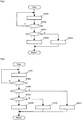
- Fig. 5 is a chart of the operation flow of the processing unit in the collision warning system according to the second embodiment of the invention.
- the processing unit 20 executes the operation flow depicted in Fig. 5 during the travel of the motorcycle 100.
- step S201 the acquisition section 21 acquires the environment information that corresponds to the output of the environment detector 11.
- the acquisition section 21 acquires the posture information related to the bank angle ⁇ L on the basis of the output of the inertial measurement unit 12.
- step S202 the determination section 22 processes the environment information acquired in step S201 and determines whether there is the possibility that the motorcycle 100 collides in consideration of the travel state information of the motorcycle 100, the rider's operation state information, and the like that are acquired by using the various detectors. If Yes, the processing proceeds to step S203. If No, the processing returns to step S201.
- step S203 the control section 23 determines whether the posture information acquired in step S201 is posture information corresponding to the bank angle ⁇ L that is smaller than a reference bank angle ⁇ Lth2. If Yes, the processing proceeds to step S204. If No, the processing proceeds to step S205.
- step S204 the control section 23 makes the warning device 30 output first warning sound in a first volume level.
- step S205 the control section 23 makes the warning device 30 output second warning sound in a second volume level that is lower than the first volume level. That is, the second warning sound is a warning with lower sensitivity than the first warning sound.
- the second warning sound may be warning sound whose volume level is gradually increased with a lapse of time.
- the first warning sound corresponds to the "first warning” in the invention
- the second warning sound corresponds to the "second warning” in the invention.
- the volume level corresponds to the "intensity" in the invention.
- the control section 23 makes the warning device 30 output a first warning display in first brightness.
- the control section 23 makes the warning device 30 output a second warning display in second brightness that is lower than the first brightness. That is, the second warning display is a warning with the lower sensitivity than the first warning display.
- the second warning display may be a warning display whose brightness is gradually increased with the lapse of time.
- the first warning display corresponds to the "first warning” in the invention
- the second warning display corresponds to the "second warning” in the invention.
- the brightness corresponds to the "intensity" in the invention.
- the control section 23 makes the warning device 30 output a first warning vibration in a first amplitude.
- the control section 23 makes the warning device 30 output a second warning vibration in a second amplitude that is smaller than the first amplitude. That is, the second warning vibration is a warning with the lower sensitivity than the first warning vibration.
- the second warning vibration may be a warning vibration whose amplitude is gradually increased with the lapse of time.
- the first warning vibration corresponds to the "first warning” in the invention
- the second warning vibration corresponds to the "second warning” in the invention.
- the amplitude corresponds to the "intensity" in the invention.
- the control section 23 makes the warning device 30 output the first warning sound whose volume level changes in a first cycle.
- the control section 23 makes the warning device 30 output the second warning sound whose volume level is changed in a second cycle that is longer than the first cycle. That is, the second warning sound is the warning with the lower sensitivity than the first warning sound.
- the second warning sound may be warning sound whose cycle in the volume level change is gradually shortened with the lapse of time.
- the first warning sound corresponds to the "first warning" in the invention
- the second warning sound corresponds to the "second warning” in the invention.
- the volume level change corresponds to the "change pattern" in the invention.
- step S204 the control section 23 makes the warning device 30 output the first warning display whose brightness changes in the first cycle.
- step S205 the control section 23 makes the warning device 30 output the second warning display whose brightness is changed in the second cycle that is longer than the first cycle. That is, the second warning display is the warning with the lower sensitivity than the first warning display.
- the second warning display may be a warning display whose cycle in the brightness change is gradually shortened with the lapse of time.
- the first warning display corresponds to the "first warning” in the invention
- the second warning display corresponds to the "second warning” in the invention.
- the brightness change corresponds to the "change pattern" in the invention.
- the control section 23 makes the warning device 30 output the first warning vibration that vibrates in the first cycle.
- the control section 23 makes the warning device 30 output the second warning vibration that vibrates in the second cycle that is longer than the first cycle. That is, the second warning vibration is the warning with the lower sensitivity than the first warning vibration.
- the second warning vibration may be a warning vibration whose cycle is gradually shortened with the lapse of time.
- the first warning vibration corresponds to the "first warning” in the invention
- the second warning vibration corresponds to the "second warning” in the invention.
- the vibration corresponds to the "change pattern" in the invention.
- the control section 23 makes the warning device 30 output the warning by a first output device that outputs sound (preferably loud sound).
- the control section 23 makes the warning device 30 output the warning by a second output device that outputs a display (preferably a less prominent display). That is, the warning by the second output device is a warning that is sensed by the rider through a different sensory organ from that used for the warning by the first output device.
- the warning by the second output device is the warning with the lower sensitivity than the warning by the first output device.
- the warning by the first output device corresponds to the "first warning" in the invention
- the warning by the second output device corresponds to the "second warning" in the invention.
- step S204 the control section 23 makes the warning device 30 output the warnings by the first output device that outputs the sound and the second output device that outputs the display.
- step S205 the control section 23 makes the warning device 30 output the warning by only the second output device. That is, the warning by the second output device in step S204 and step S205 is the warning that is sensed by the rider through the different sensory organ from that used for the warning by the first output device in step S204.
- the warning by the first output device in step S204 corresponds to the "first warning" in the invention
- the warning by the second output device in step S204 corresponds to the "third warning” in the invention
- the warning by the second output device in step S205 corresponds to the "second warning" in the invention.
- the control section 23 makes the warning device 30 output the warning by the first output device that outputs the vibration.
- the control section 23 makes the warning device 30 output the warning by the second output device that outputs the sound or the display. That is, the warning by the second output device is a warning that is sensed by the rider through the different sensory organ from that used for the warning by the first output device.
- the warning by the second output device is the warning with the lower sensitivity than the warning by the first output device.
- the warning by the first output device applies an external force to the rider, and the warning by the second output device does not apply the external force to the rider.
- the warning by the first output device corresponds to the "first warning" in the invention
- the warning by the second output device corresponds to the "second warning" in the invention.
- step S204 the control section 23 makes the warning device 30 output the warnings by the first output device that outputs the vibration and the second output device that outputs the sound or the display.
- step S205 the control section 23 makes the warning device 30 output the warning by only the second output device. That is, the warning by the second output device in step S204 and step S205 is the warning that is sensed by the rider through the different sensory organ from that used for the warning by the first output device in step S204.
- the warning by the first output device in step S204 corresponds to the "first warning" in the invention
- the warning by the second output device in step S204 corresponds to the "third warning” in the invention
- the warning by the second output device in step S205 corresponds to the "second warning" in the invention.
- the control section 23 preferably makes the warning device 30 output the first warning.
- the control section 23 preferably makes the warning device 30 output the second warning that differs from the first warning. Therefore, the rider's operation can be assisted while the rider's safety is improved.
- the second warning is preferably the warning with the lower sensitivity than the first warning.
- the rider's safety is reliably improved.
- the second warning is preferably the warning whose sensitivity is gradually improved. With such a configuration, the assistance in the rider's operation can be promoted while the rider's safety is improved.
- the second warning is preferably the warning that is sensed by the rider through the different sensory organ from that used for the first warning.
- the first warning is preferably the warning that applies the external force to the rider
- the second warning is preferably the warning that does not apply the external force to the rider.
- the rider's operation can be assisted while the rider's safety is reliably improved.
- the second warning and the third warning are preferably the warnings that are sensed by the rider through the same sensory organ. With such a configuration, the rider can be suppressed from missing the second warning, and thus the rider's safety is further reliably improved.
- collision warning system according to the third embodiment differs from the collision warning systems according to the first embodiment and the second embodiment only in terms of the operation flow of the processing unit 20.
- a description that overlaps or is similar to the descriptions on the collision warning systems according to the first embodiment and the second embodiment will appropriately be simplified or will not be made.
- Fig. 6 is a chart of the operation flow of the processing unit in the collision warning system according to the third embodiment of the invention.
- the processing unit 20 executes the operation flow depicted in Fig. 6 during the travel of the motorcycle 100.
- step S302 the determination section 22 processes the environment information acquired in step S301 and determines whether there is the possibility that the motorcycle 100 collides in consideration of the travel state information of the motorcycle 100, the rider's operation state information, and the like that are acquired by using the various detectors. If Yes, the processing proceeds to step S303. If No, the processing returns to step S301.
- step S305 the control section 23 makes the warning device 30 perform a similar operation to that in step S204 in Fig. 5 .
- step S306 the control section 23 makes the warning device 30 perform a similar operation to that in step S205 in Fig. 5 .
- step S307 the control section 23 makes the warning device 30 perform a similar operation to that in step S105 in Fig. 4 .
Landscapes
- Engineering & Computer Science (AREA)
- Radar, Positioning & Navigation (AREA)
- Remote Sensing (AREA)
- Physics & Mathematics (AREA)
- Automation & Control Theory (AREA)
- General Physics & Mathematics (AREA)
- Transportation (AREA)
- Mechanical Engineering (AREA)
- Computer Networks & Wireless Communication (AREA)
- Human Computer Interaction (AREA)
- Electromagnetism (AREA)
- Acoustics & Sound (AREA)
- Traffic Control Systems (AREA)
- Emergency Alarm Devices (AREA)
Abstract
Description
- The invention relates to a processing unit and a processing method for a collision warning system that recognizes a possibility of a collision occurred to a traveling motorcycle by using an environment detector provided in the motorcycle and warns a rider, a collision warning system that includes the processing unit, and a motorcycle that includes the collision warning system.
- As a technique related to a motorcycle (a two-wheeled motor vehicle or a three-wheeled motor vehicle), a collision warning system that recognizes a possibility of a collision occurred to a traveling motorcycle and warns a rider has been known. The collision warning system acquires environment information that corresponds to output of an environment detector provided in the motorcycle and makes a warning device output a warning when determining that there is the possibility of the collision on the basis of the environment information. The rider's operation is assisted by the warning that is output by the warning device (for example, see PTL 1).
- [PTL 1]
JP-A-2009-116882 - In the conventional collision warning system, there is a case where the warning device outputs such a warning that surprises the rider in a state where the motorcycle turns, that is, in a state where a large bank angle is generated in the motorcycle and a vehicle body becomes unstable. Thus, the rider's safety is possibly affected.
- The invention has been made with the above-described problem as the background and therefore obtains a processing unit and a processing method capable of improving a rider's safety. The invention also obtains a collision warning system that includes the processing unit. The invention further obtains a motorcycle that includes the collision warning system.
- A processing unit according to the invention is a processing unit for a collision warning system that recognizes a possibility of a collision occurred to a traveling motorcycle by using an environment detector provided in said motorcycle and warns a rider. The processing unit includes: an acquisition section that acquires environment information corresponding to output of the environment detector; a determination section that determines presence or absence of the possibility of the collision on the basis of the environment information; and a control section that makes a warning device output a warning in the case where the determination section determines that there is the possibility of the collision. During travel of the motorcycle, the acquisition section acquires posture information related to a bank angle of the motorcycle, and the control section changes the warning output by the warning device in accordance with the posture information.
- A collision warning system according to the invention includes the above processing unit, the environment detector, and the warning device.
- A motorcycle according to the invention includes the above collision warning system.
- A processing method according to the invention is a processing method for a collision warning system that recognizes a possibility of a collision occurred to a traveling motorcycle by using an environment detector provided in said motorcycle and warns a rider. The processing method includes: an acquisition step of acquiring environment information corresponding to output of the environment detector; a determination step of determining presence or absence of the possibility of the collision on the basis of the environment information; and a control step of making a warning device output a warning in the case where it is determined that there is the possibility of the collision in the determination step. During travel of the motorcycle, in the acquisition step, posture information related to a bank angle of the motorcycle is acquired, and in the control step, the warning output by the warning device is changed in accordance with the posture information.
- In the processing unit, the collision warning system, the motorcycle, and the processing method according to the invention, the warning output by the warning device is changed in accordance with the posture information related to the bank angle of the motorcycle. Therefore, in a state where the motorcycle turns, that is, in a state where the large bank angle is generated in the motorcycle and a vehicle body becomes unstable, the warning device outputs the appropriate warning, and thus the rider's safety can be improved.
-
-
Fig. 1 is a view of a state where a collision warning system according to a first embodiment of the invention is mounted on a motorcycle. -
Fig. 2 is a system configuration diagram of the collision warning system according to the first embodiment of the invention. -
Fig. 3 is a view illustrating a definition of a bank angle of the motorcycle. -
Fig. 4 is a chart of an operation flow of a processing unit in the collision warning system according to the first embodiment of the invention. -
Fig. 5 is a chart of an operation flow of a processing unit in a collision warning system according to a second embodiment of the invention. -
Fig. 6 is a chart of an operation flow of a processing unit in a collision warning system according to a third embodiment of the invention. - A description will hereinafter be made on a processing unit, a collision warning system, a motorcycle, and a processing method according to the invention by using the drawings.
- Note that each of a configuration, an operation, and the like, which will be described below, is merely one example, and the processing unit, the collision warning system, the motorcycle, and the processing method according to the invention are not limited to a case with such a configuration, such an operation, and the like.
- For example, a description will hereinafter be made on a case where the motorcycle is a two-wheeled motor vehicle; however, the motorcycle may be a three-wheeled motor vehicle. In addition, a description will hereinafter be made on a case where a possibility of a collision ahead of the motorcycle is recognized by using an environment detector that detects the front of the motorcycle. However, a possibility of a collision in another direction (a lateral direction, a rear direction, or the like) of the motorcycle may be recognized by using an environment detector that detects the other direction (the lateral direction, the rear direction, or the like) of the motorcycle.
- The same or similar description will appropriately be simplified or will not be made below. In the drawings, the same or similar portions will be denoted by the same reference signs. In addition, a detailed structure will appropriately be depicted in a simplified manner or will not be depicted.
- A description will hereinafter be made on a collision warning system according to a first embodiment.
- A description will be made on a configuration of the collision warning system according to the first embodiment.
-
Fig. 1 is a view of a state where the collision warning system according to the first embodiment of the invention is mounted on a motorcycle.Fig. 2 is a system configuration diagram of the collision warning system according to the first embodiment of the invention.Fig. 3 is a view illustrating a definition of a bank angle of the motorcycle. - As depicted in
Fig. 1 and Fig. 2 , acollision warning system 1 is mounted on amotorcycle 100. Thecollision warning system 1 at least includes anenvironment detector 11 that detects the front of themotorcycle 100, an inertial measurement unit (IMU) 12 that detects inertia generated in themotorcycle 100, a processing unit (an ECU) 20, and awarning device 30. - The
collision warning system 1 plays a role of recognizing a possibility of a collision ahead of thetraveling motorcycle 100 by using theenvironment detector 11 and a role of warning a rider by using thewarning device 30. Theprocessing unit 20 acquires output of theenvironment detector 11 and output of theinertial measurement unit 12, and outputs a control command to thewarning device 30. Theprocessing unit 20 also receives output of various detectors (not depicted) used to acquire travel state information of themotorcycle 100, the rider's operation state information, and the like, for example. Each device of thecollision warning system 1 may exclusively be used in thecollision warning system 1 or may also be used in another system. - The
environment detector 11 is a radar, a Lidar, an ultrasonic sensor, a camera, or the like, for example, and continuously detects a peripheral object (s) within a detection range during travel of themotorcycle 100. - The
inertial measurement unit 12 includes a three-axis gyroscope sensor and a three-directional acceleration sensor, for example, and outputs the detected inertia to theprocessing unit 20. Theinertial measurement unit 12 may detect another physical quantity that can substantially be converted to the inertia generated in themotorcycle 100. Alternatively, theinertial measurement unit 12 may be another detector that can acquire posture information related to a bank angle θL of themotorcycle 100. - The
processing unit 20 includes anacquisition section 21, adetermination section 22, and acontrol section 23. The sections of theprocessing unit 20 may collectively be provided in a single casing or may separately be provided in multiple casings. In addition, theprocessing unit 20 may partially or entirely be constructed of a microcomputer, a microprocessor unit, or the like, may be constructed of a member in which firmware and the like can be updated, or may be a program module or the like that is executed by a command from a CPU or the like, for example. - During the travel of the
motorcycle 100, theacquisition section 21 receives the output of theenvironment detector 11 and acquires environment information that corresponds to the output. Then, thedetermination section 22 determines whether there is a possibility that themotorcycle 100 collides by using a known method. More specifically, thedetermination section 22 processes the environment information and determines whether there is the possibility that themotorcycle 100 collides in consideration of the travel state information of themotorcycle 100, the rider's operation state information, and the like acquired by using the various detectors. Then, in the case where thedetermination section 22 determines that there is the possibility of the collision, thecontrol section 23 makes thewarning device 30 output a warning. - In addition, the
acquisition section 21 acquires the posture information related to the bank angle θL of themotorcycle 100 on the basis of the output of theinertial measurement unit 12. The posture information related to the bank angle θL may be information of the bank angle θL itself or information of another physical quantity that can substantially be converted to the bank angle θL (for example, a yaw rate, lateral acceleration, or the like generated in the motorcycle 100) . The bank angle θL is defined as a tilt angle of themotorcycle 100 in a rolling direction with respect to a state where themotorcycle 100 stands upright (seeFig. 3 ) . - The
warning device 30 may warn the rider by sound (that is, a sensation through an auditory organ as a sensory organ), may warn the rider by a display (that is, a sensation through a visual organ as the sensory organ), may warn the rider by vibrations (that is, a sensation through a tactile organ as the sensory organ), or may warn the rider by a combination of those. More specifically, thewarning device 30 is a speaker, a display, a lamp, a vibrator, or the like, and may be provided in themotorcycle 100 or may be provided in an accessory such as a helmet that is associated with themotorcycle 100. In addition, thewarning device 30 may be constructed of a single output device or may be constructed of multiple output devices of the same type or different types. The multiple output devices may be provided integrally or may be provided separately. - A description will be made on an operation of the collision warning system according to the first embodiment.
-
Fig. 4 is a chart of an operation flow of the processing unit in the collision warning system according to the first embodiment of the invention. - The
processing unit 20 executes the operation flow depicted inFig. 4 during the travel of themotorcycle 100. - In step S101, the
acquisition section 21 acquires the environment information that corresponds to the output of theenvironment detector 11. In addition, theacquisition section 21 acquires the posture information related to the bank angle θL on the basis of the output of theinertial measurement unit 12. - In step S102, the
determination section 22 processes the environment information acquired in step S101 and determines whether there is the possibility that themotorcycle 100 collides in consideration of the travel state information of themotorcycle 100, the rider's operation state information, and the like that are acquired by using the various detectors. If Yes, the processing proceeds to step S103. If No, the processing returns to step S101. - In step S103 to step S105, the
control section 23 makes thewarning device 30 output the warning in a mode that corresponds to the posture information acquired in step S101. - More specifically, in step S103, the
control section 23 determines whether the posture information acquired in step S101 is posture information corresponding to the bank angle θL that is smaller than a maximum allowable bank angle θLth1. If Yes, the processing proceeds to step S104. If No, the processing proceeds to step S105. - In step S104, the
control section 23 makes thewarning device 30 output the warning. In step S105, thecontrol section 23 does not make thewarning device 30 output the warning. In the case where a state where the determination of Yes is made in step S102 and the determination of No is made in step S103 continues for reference duration or longer, thecontrol section 23 may make thewarning device 30 output the warning. - A description will be made on effects of the collision warning system according to the first embodiment.
- The
processing unit 20 includes: theacquisition section 21 that acquires the environment information corresponding to the output of theenvironment detector 11; thedetermination section 22 that determines presence or absence of the possibility of the collision on the basis of the environment information; and thecontrol section 23 that makes thewarning device 30 output the warning in the case where thedetermination section 22 determines that there is the possibility of the collision. During the travel of themotorcycle 100, thecontrol section 23 changes the warning output by thewarning device 30 in accordance with the posture information related to the bank angle θL of themotorcycle 100. Therefore, in a state where themotorcycle 100 turns, that is, in a state where the large bank angle θL is generated in themotorcycle 100 and a vehicle body becomes unstable, thewarning device 30 outputs the appropriate warning, and thus the rider's safety can be improved. - In the case where the
acquisition section 21 acquires the posture information corresponding to the bank angle θL that is smaller than the maximum allowable bank angle θLth1, thecontrol section 23 preferably makes thewarning device 30 output the warning. In the case where theacquisition section 21 acquires the posture information corresponding to the bank angle θL that is larger than the maximum allowable bank angle θLth1, thecontrol section 23 preferably does not make thewarning device 30 output the warning. In this way, the rider's safety is reliably improved. - In particular, in the case where the state where the
determination section 22 determines that there is the possibility of the collision and theacquisition section 21 acquires the posture information corresponding to the bank angle θL that is larger than the maximum allowable bank angle θLth1 continues for the reference duration or longer, thecontrol section 23 preferably makes thewarning device 30 output the warning. With such a configuration, the rider's operation can be assisted while the rider's safety is improved. - A description will hereinafter be made on a collision warning system according to a second embodiment.
- Note that the collision warning system according to the second embodiment differs from the collision warning system according to the first embodiment only in terms of the operation flow of the
processing unit 20. A description that overlaps or is similar to the description on the collision warning system according to the first embodiment will appropriately be simplified or will not be made. - A description will be made on an operation of the collision warning system according to the second embodiment.
-
Fig. 5 is a chart of the operation flow of the processing unit in the collision warning system according to the second embodiment of the invention. - The
processing unit 20 executes the operation flow depicted inFig. 5 during the travel of themotorcycle 100. - In step S201, the
acquisition section 21 acquires the environment information that corresponds to the output of theenvironment detector 11. In addition, theacquisition section 21 acquires the posture information related to the bank angle θL on the basis of the output of theinertial measurement unit 12. - In step S202, the
determination section 22 processes the environment information acquired in step S201 and determines whether there is the possibility that themotorcycle 100 collides in consideration of the travel state information of themotorcycle 100, the rider's operation state information, and the like that are acquired by using the various detectors. If Yes, the processing proceeds to step S203. If No, the processing returns to step S201. - In step S203 to step S205, the
control section 23 makes thewarning device 30 output the warning in a mode that corresponds to the posture information acquired in step S201. - More specifically, in step S203, the
control section 23 determines whether the posture information acquired in step S201 is posture information corresponding to the bank angle θL that is smaller than a reference bank angle θLth2. If Yes, the processing proceeds to step S204. If No, the processing proceeds to step S205. - For example, in step S204, the
control section 23 makes thewarning device 30 output first warning sound in a first volume level. In step S205, thecontrol section 23 makes thewarning device 30 output second warning sound in a second volume level that is lower than the first volume level. That is, the second warning sound is a warning with lower sensitivity than the first warning sound. The second warning sound may be warning sound whose volume level is gradually increased with a lapse of time. The first warning sound corresponds to the "first warning" in the invention, and the second warning sound corresponds to the "second warning" in the invention. The volume level corresponds to the "intensity" in the invention. - For example, in step S204, the
control section 23 makes thewarning device 30 output a first warning display in first brightness. In step S205, thecontrol section 23 makes thewarning device 30 output a second warning display in second brightness that is lower than the first brightness. That is, the second warning display is a warning with the lower sensitivity than the first warning display. The second warning display may be a warning display whose brightness is gradually increased with the lapse of time. The first warning display corresponds to the "first warning" in the invention, and the second warning display corresponds to the "second warning" in the invention. The brightness corresponds to the "intensity" in the invention. - For example, in step S204, the
control section 23 makes thewarning device 30 output a first warning vibration in a first amplitude. In step S205, thecontrol section 23 makes thewarning device 30 output a second warning vibration in a second amplitude that is smaller than the first amplitude. That is, the second warning vibration is a warning with the lower sensitivity than the first warning vibration. The second warning vibration may be a warning vibration whose amplitude is gradually increased with the lapse of time. The first warning vibration corresponds to the "first warning" in the invention, and the second warning vibration corresponds to the "second warning" in the invention. The amplitude corresponds to the "intensity" in the invention. - For example, in step S204, the
control section 23 makes thewarning device 30 output the first warning sound whose volume level changes in a first cycle. In step S205, thecontrol section 23 makes thewarning device 30 output the second warning sound whose volume level is changed in a second cycle that is longer than the first cycle. That is, the second warning sound is the warning with the lower sensitivity than the first warning sound. The second warning sound may be warning sound whose cycle in the volume level change is gradually shortened with the lapse of time. The first warning sound corresponds to the "first warning" in the invention, and the second warning sound corresponds to the "second warning" in the invention. The volume level change corresponds to the "change pattern" in the invention. - For example, in step S204, the
control section 23 makes thewarning device 30 output the first warning display whose brightness changes in the first cycle. In step S205, thecontrol section 23 makes thewarning device 30 output the second warning display whose brightness is changed in the second cycle that is longer than the first cycle. That is, the second warning display is the warning with the lower sensitivity than the first warning display. The second warning display may be a warning display whose cycle in the brightness change is gradually shortened with the lapse of time. The first warning display corresponds to the "first warning" in the invention, and the second warning display corresponds to the "second warning" in the invention. The brightness change corresponds to the "change pattern" in the invention. - For example, in step S204, the
control section 23 makes thewarning device 30 output the first warning vibration that vibrates in the first cycle. In step S205, thecontrol section 23 makes thewarning device 30 output the second warning vibration that vibrates in the second cycle that is longer than the first cycle. That is, the second warning vibration is the warning with the lower sensitivity than the first warning vibration. The second warning vibration may be a warning vibration whose cycle is gradually shortened with the lapse of time. The first warning vibration corresponds to the "first warning" in the invention, and the second warning vibration corresponds to the "second warning" in the invention. The vibration corresponds to the "change pattern" in the invention. - For example, in step S204, the
control section 23 makes thewarning device 30 output the warning by a first output device that outputs sound (preferably loud sound). In step S205, thecontrol section 23 makes thewarning device 30 output the warning by a second output device that outputs a display (preferably a less prominent display). That is, the warning by the second output device is a warning that is sensed by the rider through a different sensory organ from that used for the warning by the first output device. In addition, the warning by the second output device is the warning with the lower sensitivity than the warning by the first output device. The warning by the first output device corresponds to the "first warning" in the invention, and the warning by the second output device corresponds to the "second warning" in the invention. - For example, in step S204, the
control section 23 makes thewarning device 30 output the warnings by the first output device that outputs the sound and the second output device that outputs the display. In step S205, thecontrol section 23 makes thewarning device 30 output the warning by only the second output device. That is, the warning by the second output device in step S204 and step S205 is the warning that is sensed by the rider through the different sensory organ from that used for the warning by the first output device in step S204. The warning by the first output device in step S204 corresponds to the "first warning" in the invention, the warning by the second output device in step S204 corresponds to the "third warning" in the invention, and the warning by the second output device in step S205 corresponds to the "second warning" in the invention. - For example, in step S204, the
control section 23 makes thewarning device 30 output the warning by the first output device that outputs the vibration. In step S205, thecontrol section 23 makes thewarning device 30 output the warning by the second output device that outputs the sound or the display. That is, the warning by the second output device is a warning that is sensed by the rider through the different sensory organ from that used for the warning by the first output device. In addition, the warning by the second output device is the warning with the lower sensitivity than the warning by the first output device. Furthermore, the warning by the first output device applies an external force to the rider, and the warning by the second output device does not apply the external force to the rider. The warning by the first output device corresponds to the "first warning" in the invention, and the warning by the second output device corresponds to the "second warning" in the invention. - For example, in step S204, the
control section 23 makes thewarning device 30 output the warnings by the first output device that outputs the vibration and the second output device that outputs the sound or the display. In step S205, thecontrol section 23 makes thewarning device 30 output the warning by only the second output device. That is, the warning by the second output device in step S204 and step S205 is the warning that is sensed by the rider through the different sensory organ from that used for the warning by the first output device in step S204. The warning by the first output device in step S204 corresponds to the "first warning" in the invention, the warning by the second output device in step S204 corresponds to the "third warning" in the invention, and the warning by the second output device in step S205 corresponds to the "second warning" in the invention. - A description will be made on effects of the collision warning system according to the second embodiment.
- In the case where the
acquisition section 21 acquires the posture information corresponding to the bank angle θL that is smaller than the reference bank angle θLth2, thecontrol section 23 preferably makes thewarning device 30 output the first warning. In the case where theacquisition section 21 acquires the posture information corresponding to the bank angle θL that is larger than the reference bank angle θLth2, thecontrol section 23 preferably makes thewarning device 30 output the second warning that differs from the first warning. Therefore, the rider's operation can be assisted while the rider's safety is improved. - In particular, the second warning is preferably the warning with the lower sensitivity than the first warning. With such a configuration, the rider's safety is reliably improved. Furthermore, the second warning is preferably the warning whose sensitivity is gradually improved. With such a configuration, the assistance in the rider's operation can be promoted while the rider's safety is improved.
- In addition, in particular, the second warning is preferably the warning that is sensed by the rider through the different sensory organ from that used for the first warning. With such a configuration, the rider's safety is reliably improved. Furthermore, the first warning is preferably the warning that applies the external force to the rider, and the second warning is preferably the warning that does not apply the external force to the rider. With such a configuration, in the state where the large bank angle θL is generated in the
motorcycle 100 and the vehicle body becomes unstable, the application of the external force to the rider is suppressed. Therefore, the rider's operation can be assisted while the rider's safety is reliably improved. - Moreover, in particular, the second warning is preferably the warning that is sensed by the rider through the different sensory organ from that used for the first warning. In the case where the
acquisition section 21 acquires the posture information corresponding to the bank angle θL that is smaller than the reference bank angle θLth2, thecontrol section 23 preferably makes thewarning device 30 output the third warning, which is sensed by the rider through the different sensory organ from that used for the first warning, in addition to the first warning. In the case where theacquisition section 21 acquires the posture information corresponding to the bank angle θL that is larger than the reference bank angle θLth2, thecontrol section 23 preferably does not make thewarning device 30 output the third warning. With such a configuration, the rider's operation can be assisted while the rider's safety is reliably improved. Furthermore, the second warning and the third warning are preferably the warnings that are sensed by the rider through the same sensory organ. With such a configuration, the rider can be suppressed from missing the second warning, and thus the rider's safety is further reliably improved. - A description will hereinafter be made on a collision warning system according to a third embodiment.
- Note that the collision warning system according to the third embodiment differs from the collision warning systems according to the first embodiment and the second embodiment only in terms of the operation flow of the
processing unit 20. A description that overlaps or is similar to the descriptions on the collision warning systems according to the first embodiment and the second embodiment will appropriately be simplified or will not be made. - A description will be made on an operation of the collision warning system according to the third embodiment.
-
Fig. 6 is a chart of the operation flow of the processing unit in the collision warning system according to the third embodiment of the invention. - The
processing unit 20 executes the operation flow depicted inFig. 6 during the travel of themotorcycle 100. - In step S301, the
acquisition section 21 acquires the environment information that corresponds to the output of theenvironment detector 11. In addition, theacquisition section 21 acquires the posture information related to the bank angle θL on the basis of the output of theinertial measurement unit 12. - In step S302, the
determination section 22 processes the environment information acquired in step S301 and determines whether there is the possibility that themotorcycle 100 collides in consideration of the travel state information of themotorcycle 100, the rider's operation state information, and the like that are acquired by using the various detectors. If Yes, the processing proceeds to step S303. If No, the processing returns to step S301. - In step S303 to step S307, the
control section 23 makes thewarning device 30 output the warning in a mode that corresponds to the posture information acquired in step S301. - More specifically, in step S303, the
control section 23 determines whether the posture information acquired in step S301 is the posture information corresponding to the bank angle θL that is smaller than the maximum allowable bank angle θLth1. If Yes, the processing proceeds to step S304. If No, the processing proceeds to step S307. - In step S304, the
control section 23 determines whether the posture information acquired in step S301 is the posture information corresponding to the bank angle θL that is smaller than the reference bank angle θLth2. Note that the reference bank angle θLth2 is the smaller angle than the maximum allowable bank angle θLth1. If Yes, the processing proceeds to step S305. If No, the processing proceeds to step S306. - In step S305, the
control section 23 makes thewarning device 30 perform a similar operation to that in step S204 inFig. 5 . In step S306, thecontrol section 23 makes thewarning device 30 perform a similar operation to that in step S205 inFig. 5 . In step S307, thecontrol section 23 makes thewarning device 30 perform a similar operation to that in step S105 inFig. 4 . - A description will be made on effects of the collision warning system according to the third embodiment.
- In the case where the
acquisition section 21 acquires the posture information corresponding to the bank angle θL that is smaller than the reference bank angle θLth2, thecontrol section 23 preferably makes thewarning device 30 output the first warning. In the case where theacquisition section 21 acquires the posture information corresponding to the bank angle θL that is larger than the reference bank angle θLth2 and is smaller than the maximum allowable bank angle θLth1, thecontrol section 23 preferably makes thewarning device 30 output the second warning that differs from the first warning. In the case where theacquisition section 21 acquires the posture information corresponding to the bank angle θL that is larger than the maximum allowable bank angle θLth1, thecontrol section 23 preferably does not make thewarning device 30 output the warning. Therefore, the assistance in the rider's operation can further reliably be improved while the rider's safety is improved. - The description has been made so far on the first embodiment to the third embodiment. However, the invention is not limited to the description of each of the embodiments. For example, only a part of each of the embodiments may be implemented, or all or parts of the embodiments may be combined. In addition, all or parts of the steps in each of the operation flows may be executed in a different order. For example, the acquisition of the posture information related to the bank angle θL in the acquisition steps S101, S201, S301 may be executed after the determination steps S102, S202, S302. Furthermore, in the second embodiment and the third embodiment, the two types of the warnings are used differently by using the reference bank angle θLth2. However, three or more types of the warnings may be used differently.
-
- 1:
- Collision warning system
- 11:
- Environment detector
- 12:
- Inertial measurement unit
- 20:
- Processing unit
- 21:
- Acquisition section
- 22:
- Determination section
- 23:
- Control section
- 30:
- Warning device
- 100:
- Motorcycle
- θL:
- Bank angle
- θLth1:
- Maximum allowable bank angle
- θLth2:
- Reference bank angle
Claims (15)
- A processing unit (20) for a collision warning system (1) that recognizes a possibility of a collision occurred to a traveling motorcycle (100) by using an environment detector (11) provided in said motorcycle (100) and warns a rider, the processing unit (20) comprising:an acquisition section (21) that acquires environment information corresponding to output of the environment detector (11);a determination section (22) that determines presence or absence of the possibility of the collision on the basis of the environment information; anda control section (23) that makes a warning device (30) output a warning in the case where the determination section (22) determines that there is the possibility of the collision, whereinduring travel of the motorcycle (100),the acquisition section (21) acquires posture information related to a bank angle (θL) of the motorcycle (100), andthe control section (23) changes the warning output by the warning device (30) in accordance with the posture information.
- The processing unit (20) according to claim 1, wherein
during the travel of the motorcycle (100),
the control section (23) makes the warning device (30) output the warning in the case where the acquisition section (21) acquires the posture information corresponding to the bank angle (θL) that is smaller than a maximum allowable bank angle (θLth1), and does not make the warning device (30) output the warning in the case where the acquisition section (21) acquires the posture information corresponding to the bank angle (θL) that is larger than the maximum allowable bank angle (θLth1). - The processing unit (20) according to claim 2, wherein
during the travel of the motorcycle (100),
the control section (23) makes the warning device (30) output the warning in the case where a state where the determination section (22) determines that there is the possibility of the collision and the acquisition section (21) acquires the posture information corresponding to the bank angle (θL) that is larger than the maximum allowable bank angle (θLth1) continues for reference duration or longer. - The processing unit (20) according to any one of claims 1 to 3, wherein
during the travel of the motorcycle (100),
the control section (23) makes the warning device (30) output a first warning in the case where the acquisition section (21) acquires the posture information corresponding to the bank angle (θL) that is smaller than a reference bank angle (θLth2), and makes the warning device (30) output a second warning that differs from the first warning in the case where the acquisition section (21) acquires the posture information corresponding to the bank angle (θL) that is larger than the reference bank angle (θLth2). - The processing unit (20) according to claim 4, wherein
the second warning is a warning with lower sensitivity than the first warning. - The processing unit (20) according to claim 5, wherein
the second warning is a warning whose sensitivity is gradually improved. - The processing unit (20) according to claim 5 or 6, wherein
the second warning is a warning whose intensity of output is lower than the first warning. - The processing unit (20) according to any one of claims 5 to 7, wherein
the second warning is a warning that is output in a change pattern of a longer cycle than the first warning. - The processing unit (20) according to claim 4 or 5, wherein
the second warning is a warning that is sensed by the rider through a different sensory organ from a sensory organ used for the first warning. - The processing unit (20) according to claim 9, wherein
the first warning is a warning that applies an external force to the rider, and
the second warning is a warning that does not apply the external force to the rider. - The processing unit (20) according to claim 9 or 10, wherein
during the travel of the motorcycle (100),
the control section (23) makes the warning device (30) output the first warning and a third warning that is sensed by the rider through a different sensory organ from the sensory organ used for said first warning in the case where the acquisition section (21) acquires the posture information corresponding to the bank angle (θL) that is smaller than the reference bank angle (θLth2), and does not make the warning device (30) output the third warning in the case where the acquisition section (21) acquires the posture information corresponding to the bank angle (θL) that is larger than the reference bank angle (θLth2). - The processing unit (20) according to claim 11, wherein
the second warning and the third warning are warnings that are sensed by the rider through the same sensory organ. - A collision warning system (1) comprising:the processing unit (20) according to any one of claims 1 to 12;the environment detector (11); andthe warning device (30).
- A motorcycle (100) comprising:
the collision warning system (1) according to claim 13. - A processing method for a collision warning system (1) that recognizes a possibility of a collision occurred to a traveling motorcycle (100) by using an environment detector (11) provided in said motorcycle (100) and warns a rider, the processing method comprising:an acquisition step (S101, S201, S301) of acquiring environment information corresponding to output of the environment detector (11);a determination step (S102, S202, S302) of determining presence or absence of the possibility of the collision on the basis of the environment information; anda control step (S103 to S105, S203 to S205, S303 to S307) of making a warning device (30) output a warning in the case where it is determined that there is the possibility of the collision in the determination step (S102, S202, S302), whereinduring travel of the motorcycle (100),in the acquisition step (S101, S201, S301), posture information related to a bank angle (θL) of the motorcycle (100) is acquired, andin the control step (S103 to S105, S203 to S205, S303 to S307), the warning output by the warning device (30) is changed in accordance with the posture information.
Applications Claiming Priority (2)
| Application Number | Priority Date | Filing Date | Title |
|---|---|---|---|
| JP2017115127A JP2019003262A (en) | 2017-06-12 | 2017-06-12 | Processing unit and processing method for collision warning system, collision warning system, and motor cycle |
| PCT/IB2018/053369 WO2018229565A1 (en) | 2017-06-12 | 2018-05-15 | Processing unit and processing method for collision warning system, collision warning system, and motorcycle |
Publications (1)
| Publication Number | Publication Date |
|---|---|
| EP3640916A1 true EP3640916A1 (en) | 2020-04-22 |
Family
ID=62528782
Family Applications (1)
| Application Number | Title | Priority Date | Filing Date |
|---|---|---|---|
| EP18729197.6A Ceased EP3640916A1 (en) | 2017-06-12 | 2018-05-15 | Processing unit and processing method for collision warning system, collision warning system, and motorcycle |
Country Status (5)
| Country | Link |
|---|---|
| US (1) | US11685372B2 (en) |
| EP (1) | EP3640916A1 (en) |
| JP (2) | JP2019003262A (en) |
| CN (1) | CN110914886A (en) |
| WO (1) | WO2018229565A1 (en) |
Cited By (1)
| Publication number | Priority date | Publication date | Assignee | Title |
|---|---|---|---|---|
| WO2026069032A1 (en) * | 2024-09-26 | 2026-04-02 | ロベルト•ボッシュ•ゲゼルシャフト•ミト•ベシュレンクテル•ハフツング | Control device and control method |
Families Citing this family (7)
| Publication number | Priority date | Publication date | Assignee | Title |
|---|---|---|---|---|
| JP7364446B2 (en) * | 2019-08-27 | 2023-10-18 | ロベルト・ボッシュ・ゲゼルシャフト・ミト・ベシュレンクテル・ハフツング | Rider support system and rider support system control method |
| JP2022007245A (en) * | 2020-06-26 | 2022-01-13 | ロベルト・ボッシュ・ゲゼルシャフト・ミト・ベシュレンクテル・ハフツング | Control device of rider support system, rider support system, and control method of rider support system |
| JP7650150B2 (en) * | 2020-12-21 | 2025-03-24 | ロベルト・ボッシュ・ゲゼルシャフト・ミト・ベシュレンクテル・ハフツング | Helmet, rider support system, and control method thereof |
| JP7284209B2 (en) * | 2021-03-31 | 2023-05-30 | 本田技研工業株式会社 | Driving support system for motorcycles |
| CN114333318B (en) * | 2021-12-31 | 2023-04-28 | 成都路行通信息技术有限公司 | Motorcycle collision detection method based on sensor space angle |
| WO2023145166A1 (en) * | 2022-01-26 | 2023-08-03 | 本田技研工業株式会社 | Saddle-riding type vehicle and tactile stimulation system |
| WO2025024916A1 (en) * | 2023-08-02 | 2025-02-06 | Damon Motors Inc. | Lean-compensated position and trajectory of motorcycle |
Citations (3)
| Publication number | Priority date | Publication date | Assignee | Title |
|---|---|---|---|---|
| DE102014225625A1 (en) * | 2014-12-11 | 2016-06-16 | Bayerische Motoren Werke Aktiengesellschaft | A method of assisting a driver of a single-track motor vehicle to safely drive a turn |
| US20170144665A1 (en) * | 2014-08-04 | 2017-05-25 | Kabushiki Kaisha F.C.C. | Saddled vehicle |
| US20170158118A1 (en) * | 2015-12-04 | 2017-06-08 | Karl Lenker | Systems and Methods for Motorbike Collision Avoidance |
Family Cites Families (11)
| Publication number | Priority date | Publication date | Assignee | Title |
|---|---|---|---|---|
| JP4427964B2 (en) * | 2003-03-31 | 2010-03-10 | 株式会社アドヴィックス | Vehicle control device |
| DE102007053274B4 (en) | 2007-11-08 | 2020-12-10 | Robert Bosch Gmbh | Driver assistance system for especially motorized two-wheelers |
| CN101811487A (en) | 2010-04-13 | 2010-08-25 | 北京交通大学 | Anti-rollover tilt alarm device for automobile |
| JP5752379B2 (en) * | 2010-09-22 | 2015-07-22 | 川崎重工業株式会社 | Vehicle bank angle detector |
| DE102012214547A1 (en) * | 2012-08-16 | 2014-02-20 | Robert Bosch Gmbh | Method for monitoring a blind spot and driver assistance system |
| DE102013021827B4 (en) * | 2013-12-21 | 2025-12-31 | Valeo Schalter Und Sensoren Gmbh | Method for warning a driver of a motor vehicle of a collision hazard by issuing a non-optical warning signal, collision warning system and motor vehicle |
| US11352090B2 (en) * | 2014-07-28 | 2022-06-07 | Robert Bosch Gmbh | Information providing device and program for motorcycle |
| US9290174B1 (en) * | 2014-10-23 | 2016-03-22 | GM Global Technology Operations LLC | Method and system for mitigating the effects of an impaired driver |
| CN104276049B (en) * | 2014-10-28 | 2017-01-25 | 广西一定能电子科技有限公司 | Circuit device capable of automatically cutting off speed controller during lateral inclining or toppling over of electric vehicle |
| KR101641490B1 (en) * | 2014-12-10 | 2016-07-21 | 엘지전자 주식회사 | Driver assistance apparatus and Vehicle including the same |
| US9384645B1 (en) * | 2015-01-20 | 2016-07-05 | Elwha Llc | System and method for impact prediction and proximity warning |
-
2017
- 2017-06-12 JP JP2017115127A patent/JP2019003262A/en active Pending
-
2018
- 2018-05-15 CN CN201880052177.2A patent/CN110914886A/en active Pending
- 2018-05-15 WO PCT/IB2018/053369 patent/WO2018229565A1/en not_active Ceased
- 2018-05-15 US US16/621,790 patent/US11685372B2/en active Active
- 2018-05-15 JP JP2019524535A patent/JP7104035B2/en active Active
- 2018-05-15 EP EP18729197.6A patent/EP3640916A1/en not_active Ceased
Patent Citations (3)
| Publication number | Priority date | Publication date | Assignee | Title |
|---|---|---|---|---|
| US20170144665A1 (en) * | 2014-08-04 | 2017-05-25 | Kabushiki Kaisha F.C.C. | Saddled vehicle |
| DE102014225625A1 (en) * | 2014-12-11 | 2016-06-16 | Bayerische Motoren Werke Aktiengesellschaft | A method of assisting a driver of a single-track motor vehicle to safely drive a turn |
| US20170158118A1 (en) * | 2015-12-04 | 2017-06-08 | Karl Lenker | Systems and Methods for Motorbike Collision Avoidance |
Non-Patent Citations (1)
| Title |
|---|
| See also references of WO2018229565A1 * |
Cited By (1)
| Publication number | Priority date | Publication date | Assignee | Title |
|---|---|---|---|---|
| WO2026069032A1 (en) * | 2024-09-26 | 2026-04-02 | ロベルト•ボッシュ•ゲゼルシャフト•ミト•ベシュレンクテル•ハフツング | Control device and control method |
Also Published As
| Publication number | Publication date |
|---|---|
| US20210139021A1 (en) | 2021-05-13 |
| WO2018229565A1 (en) | 2018-12-20 |
| JP7104035B2 (en) | 2022-07-20 |
| JP2019003262A (en) | 2019-01-10 |
| JPWO2018229565A1 (en) | 2020-03-26 |
| CN110914886A (en) | 2020-03-24 |
| US11685372B2 (en) | 2023-06-27 |
Similar Documents
| Publication | Publication Date | Title |
|---|---|---|
| EP3640916A1 (en) | Processing unit and processing method for collision warning system, collision warning system, and motorcycle | |
| JP6631545B2 (en) | Dependency estimator | |
| US10482745B2 (en) | Head lowering and turning reminding device, control method thereof and helmet | |
| EP3640917A1 (en) | Processing unit and processing method for intervehicular distance warning system, intervehicular distance warning system, and motorcycle | |
| JP2019527387A5 (en) | ||
| JPWO2016017297A1 (en) | Information providing apparatus and program for motorcycle | |
| US11634151B2 (en) | Processor and processing method for warning system of straddle-type vehicle, warning system of straddle-type vehicle, and straddle-type vehicle | |
| WO2013046298A1 (en) | Vehicle driving assistance system | |
| JP2015107798A (en) | Method and apparatus for detecting the fall of a driver of a motorcycle | |
| EP4331937B1 (en) | Control device and control method for rider assistance system | |
| JP2015141553A (en) | Risk avoidance control device, risk avoidance control method, and program | |
| KR102179579B1 (en) | Car steering wheel of the integrated smart navigation | |
| JP6328016B2 (en) | In-vehicle system | |
| JP6238016B2 (en) | Vehicle driving support device | |
| JP2019179511A (en) | Driving support system, information processing apparatus, and driving support method | |
| KR102474807B1 (en) | Hands-off worning apparatus and method for steering wheel | |
| EP4563386B1 (en) | Apparatus for detecting warning light and displaying alternative warning light, and method for the same | |
| JP5831632B2 (en) | Driving support control device | |
| JP7798628B2 (en) | Information processing device, information processing method, program, and storage medium | |
| KR20170032714A (en) | Vehicle control apparatus and control method thereof | |
| JP2014149627A (en) | Driving support device and driving support method |
Legal Events
| Date | Code | Title | Description |
|---|---|---|---|
| STAA | Information on the status of an ep patent application or granted ep patent |
Free format text: STATUS: UNKNOWN |
|
| STAA | Information on the status of an ep patent application or granted ep patent |
Free format text: STATUS: THE INTERNATIONAL PUBLICATION HAS BEEN MADE |
|
| PUAI | Public reference made under article 153(3) epc to a published international application that has entered the european phase |
Free format text: ORIGINAL CODE: 0009012 |
|
| STAA | Information on the status of an ep patent application or granted ep patent |
Free format text: STATUS: REQUEST FOR EXAMINATION WAS MADE |
|
| 17P | Request for examination filed |
Effective date: 20200113 |
|
| AK | Designated contracting states |
Kind code of ref document: A1 Designated state(s): AL AT BE BG CH CY CZ DE DK EE ES FI FR GB GR HR HU IE IS IT LI LT LU LV MC MK MT NL NO PL PT RO RS SE SI SK SM TR |
|
| AX | Request for extension of the european patent |
Extension state: BA ME |
|
| RAP1 | Party data changed (applicant data changed or rights of an application transferred) |
Owner name: ROBERT BOSCH GMBH |
|
| DAV | Request for validation of the european patent (deleted) | ||
| DAX | Request for extension of the european patent (deleted) | ||
| GRAJ | Information related to disapproval of communication of intention to grant by the applicant or resumption of examination proceedings by the epo deleted |
Free format text: ORIGINAL CODE: EPIDOSDIGR1 |
|
| GRAP | Despatch of communication of intention to grant a patent |
Free format text: ORIGINAL CODE: EPIDOSNIGR1 |
|
| STAA | Information on the status of an ep patent application or granted ep patent |
Free format text: STATUS: EXAMINATION IS IN PROGRESS |
|
| 17Q | First examination report despatched |
Effective date: 20210202 |
|
| APBK | Appeal reference recorded |
Free format text: ORIGINAL CODE: EPIDOSNREFNE |
|
| APBN | Date of receipt of notice of appeal recorded |
Free format text: ORIGINAL CODE: EPIDOSNNOA2E |
|
| APBR | Date of receipt of statement of grounds of appeal recorded |
Free format text: ORIGINAL CODE: EPIDOSNNOA3E |
|
| APAF | Appeal reference modified |
Free format text: ORIGINAL CODE: EPIDOSCREFNE |
|
| APAF | Appeal reference modified |
Free format text: ORIGINAL CODE: EPIDOSCREFNE |
|
| REG | Reference to a national code |
Ref country code: DE Ref legal event code: R003 |
|
| APBT | Appeal procedure closed |
Free format text: ORIGINAL CODE: EPIDOSNNOA9E |
|
| STAA | Information on the status of an ep patent application or granted ep patent |
Free format text: STATUS: THE APPLICATION HAS BEEN REFUSED |
|
| 18R | Application refused |
Effective date: 20250715 |