EP3640896B1 - Vehicle door handle with near field communication electronics - Google Patents
Vehicle door handle with near field communication electronics Download PDFInfo
- Publication number
- EP3640896B1 EP3640896B1 EP19188577.1A EP19188577A EP3640896B1 EP 3640896 B1 EP3640896 B1 EP 3640896B1 EP 19188577 A EP19188577 A EP 19188577A EP 3640896 B1 EP3640896 B1 EP 3640896B1
- Authority
- EP
- European Patent Office
- Prior art keywords
- coil
- field communication
- housing
- control circuit
- metallic component
- Prior art date
- Legal status (The legal status is an assumption and is not a legal conclusion. Google has not performed a legal analysis and makes no representation as to the accuracy of the status listed.)
- Active
Links
- 238000004891 communication Methods 0.000 title claims description 85
- 238000000034 method Methods 0.000 claims description 9
- 239000004020 conductor Substances 0.000 claims description 7
- 238000007667 floating Methods 0.000 claims description 4
- 238000001514 detection method Methods 0.000 claims description 3
- 230000003213 activating effect Effects 0.000 claims 1
- 230000001939 inductive effect Effects 0.000 description 7
- 238000013475 authorization Methods 0.000 description 3
- 238000013461 design Methods 0.000 description 3
- 239000002184 metal Substances 0.000 description 3
- 238000004519 manufacturing process Methods 0.000 description 2
- 238000004026 adhesive bonding Methods 0.000 description 1
- 238000013459 approach Methods 0.000 description 1
- 230000005540 biological transmission Effects 0.000 description 1
- 238000012790 confirmation Methods 0.000 description 1
- 230000008878 coupling Effects 0.000 description 1
- 238000010168 coupling process Methods 0.000 description 1
- 238000005859 coupling reaction Methods 0.000 description 1
- 230000001419 dependent effect Effects 0.000 description 1
- 230000000694 effects Effects 0.000 description 1
- 238000005516 engineering process Methods 0.000 description 1
- 230000007613 environmental effect Effects 0.000 description 1
- 239000011888 foil Substances 0.000 description 1
- 238000005259 measurement Methods 0.000 description 1
- 238000012986 modification Methods 0.000 description 1
- 230000004048 modification Effects 0.000 description 1
- 239000003973 paint Substances 0.000 description 1
- 238000005507 spraying Methods 0.000 description 1
- 230000002123 temporal effect Effects 0.000 description 1
- 238000012795 verification Methods 0.000 description 1
Images


Classifications
-
- G—PHYSICS
- G07—CHECKING-DEVICES
- G07C—TIME OR ATTENDANCE REGISTERS; REGISTERING OR INDICATING THE WORKING OF MACHINES; GENERATING RANDOM NUMBERS; VOTING OR LOTTERY APPARATUS; ARRANGEMENTS, SYSTEMS OR APPARATUS FOR CHECKING NOT PROVIDED FOR ELSEWHERE
- G07C9/00—Individual registration on entry or exit
- G07C9/00174—Electronically operated locks; Circuits therefor; Nonmechanical keys therefor, e.g. passive or active electrical keys or other data carriers without mechanical keys
- G07C9/00309—Electronically operated locks; Circuits therefor; Nonmechanical keys therefor, e.g. passive or active electrical keys or other data carriers without mechanical keys operated with bidirectional data transmission between data carrier and locks
-
- E—FIXED CONSTRUCTIONS
- E05—LOCKS; KEYS; WINDOW OR DOOR FITTINGS; SAFES
- E05B—LOCKS; ACCESSORIES THEREFOR; HANDCUFFS
- E05B81/00—Power-actuated vehicle locks
- E05B81/54—Electrical circuits
- E05B81/64—Monitoring or sensing, e.g. by using switches or sensors
- E05B81/76—Detection of handle operation; Detection of a user approaching a handle; Electrical switching actions performed by door handles
- E05B81/77—Detection of handle operation; Detection of a user approaching a handle; Electrical switching actions performed by door handles comprising sensors detecting the presence of the hand of a user
-
- H—ELECTRICITY
- H01—ELECTRIC ELEMENTS
- H01Q—ANTENNAS, i.e. RADIO AERIALS
- H01Q1/00—Details of, or arrangements associated with, antennas
- H01Q1/27—Adaptation for use in or on movable bodies
- H01Q1/32—Adaptation for use in or on road or rail vehicles
- H01Q1/3208—Adaptation for use in or on road or rail vehicles characterised by the application wherein the antenna is used
- H01Q1/3233—Adaptation for use in or on road or rail vehicles characterised by the application wherein the antenna is used particular used as part of a sensor or in a security system, e.g. for automotive radar, navigation systems
- H01Q1/3241—Adaptation for use in or on road or rail vehicles characterised by the application wherein the antenna is used particular used as part of a sensor or in a security system, e.g. for automotive radar, navigation systems particular used in keyless entry systems
-
- H—ELECTRICITY
- H01—ELECTRIC ELEMENTS
- H01Q—ANTENNAS, i.e. RADIO AERIALS
- H01Q1/00—Details of, or arrangements associated with, antennas
- H01Q1/27—Adaptation for use in or on movable bodies
- H01Q1/32—Adaptation for use in or on road or rail vehicles
- H01Q1/325—Adaptation for use in or on road or rail vehicles characterised by the location of the antenna on the vehicle
- H01Q1/3283—Adaptation for use in or on road or rail vehicles characterised by the location of the antenna on the vehicle side-mounted antennas, e.g. bumper-mounted, door-mounted
-
- H—ELECTRICITY
- H03—ELECTRONIC CIRCUITRY
- H03K—PULSE TECHNIQUE
- H03K17/00—Electronic switching or gating, i.e. not by contact-making and –breaking
- H03K17/94—Electronic switching or gating, i.e. not by contact-making and –breaking characterised by the way in which the control signals are generated
- H03K17/965—Switches controlled by moving an element forming part of the switch
- H03K17/97—Switches controlled by moving an element forming part of the switch using a magnetic movable element
-
- H04B5/26—
-
- H04B5/72—
-
- G—PHYSICS
- G07—CHECKING-DEVICES
- G07C—TIME OR ATTENDANCE REGISTERS; REGISTERING OR INDICATING THE WORKING OF MACHINES; GENERATING RANDOM NUMBERS; VOTING OR LOTTERY APPARATUS; ARRANGEMENTS, SYSTEMS OR APPARATUS FOR CHECKING NOT PROVIDED FOR ELSEWHERE
- G07C9/00—Individual registration on entry or exit
- G07C9/00174—Electronically operated locks; Circuits therefor; Nonmechanical keys therefor, e.g. passive or active electrical keys or other data carriers without mechanical keys
- G07C9/00309—Electronically operated locks; Circuits therefor; Nonmechanical keys therefor, e.g. passive or active electrical keys or other data carriers without mechanical keys operated with bidirectional data transmission between data carrier and locks
- G07C2009/00365—Electronically operated locks; Circuits therefor; Nonmechanical keys therefor, e.g. passive or active electrical keys or other data carriers without mechanical keys operated with bidirectional data transmission between data carrier and locks in combination with a wake-up circuit
- G07C2009/00373—Electronically operated locks; Circuits therefor; Nonmechanical keys therefor, e.g. passive or active electrical keys or other data carriers without mechanical keys operated with bidirectional data transmission between data carrier and locks in combination with a wake-up circuit whereby the wake-up circuit is situated in the lock
-
- G—PHYSICS
- G07—CHECKING-DEVICES
- G07C—TIME OR ATTENDANCE REGISTERS; REGISTERING OR INDICATING THE WORKING OF MACHINES; GENERATING RANDOM NUMBERS; VOTING OR LOTTERY APPARATUS; ARRANGEMENTS, SYSTEMS OR APPARATUS FOR CHECKING NOT PROVIDED FOR ELSEWHERE
- G07C2209/00—Indexing scheme relating to groups G07C9/00 - G07C9/38
- G07C2209/60—Indexing scheme relating to groups G07C9/00174 - G07C9/00944
- G07C2209/63—Comprising locating means for detecting the position of the data carrier, i.e. within the vehicle or within a certain distance from the vehicle
- G07C2209/65—Comprising locating means for detecting the position of the data carrier, i.e. within the vehicle or within a certain distance from the vehicle using means for sensing the user's hand
-
- H—ELECTRICITY
- H03—ELECTRONIC CIRCUITRY
- H03K—PULSE TECHNIQUE
- H03K17/00—Electronic switching or gating, i.e. not by contact-making and –breaking
- H03K17/94—Electronic switching or gating, i.e. not by contact-making and –breaking characterised by the way in which the control signals are generated
- H03K17/965—Switches controlled by moving an element forming part of the switch
- H03K17/97—Switches controlled by moving an element forming part of the switch using a magnetic movable element
- H03K2017/9706—Inductive element
Definitions
- the invention relates to a vehicle door handle for motor vehicles, wherein the vehicle door handle has a handle which can be mounted on a vehicle via a fastening section coupled thereto.
- the handle of the vehicle door handle has a housing in which near-field communication electronics are accommodated.
- This near-field communication electronics contains an oscillating circuit with a coil.
- a control circuit is coupled to the near-field communication electronics. If the control circuit controls the near-field communication electronics in a communication mode, the coil of the resonant circuit is operated as a transmitter-receiver coil for near-field communication.
- Vehicle door handles of the type mentioned are known in the art.
- the document discloses DE 10 2013 102 701 A1 a door handle arrangement for vehicles, wherein both a capacitive proximity sensor and near-field communication electronics in the form of an NFC (Near Field Communication) transceiver unit are accommodated in the vehicle door handle.
- NFC Near Field Communication
- data can be exchanged between an external data carrier, for example a card with an NFC transponder or an electronic mobile device (in particular a smartphone) and the door handle-side near-field communication electronics, provided that both communication partners are sufficiently close to one another.
- an external data carrier for example a card with an NFC transponder or an electronic mobile device (in particular a smartphone)
- authorization information can be transmitted to the vehicle from a mobile device capable of near-field communication or another data carrier and depending on the verification This data is used to grant authorizations and access to the vehicle.
- NFC Near-field communication
- RFID Radio-Frequency Identification
- the other device can be a passive device, e.g. the key card for a vehicle.
- This device does not require its own energy source (but it can easily be an active device) but only its own resonant circuit (antenna), which is tuned to approximately 13.56MHz.
- the magnetic field of the active device induces a voltage there - both devices are then inductively coupled.
- a device can vary its resonant circuit (load modulation). The active device registers a changed inductive load - this way data is exchanged. Since the technology is known, reference is made to the standardization specifications and the specialist literature.
- a coil for example a wire coil or conductor coil on a circuit board, is operated in a resonant circuit and the data exchange is transmitted through variations of the operating parameters on the transmitter and receiver sides.
- a coil with sufficient size in particular with a sufficient coil cross-section, should be aimed for, whereby this is: very limited space available in a vehicle door handle. If a sensor system for detecting manual handle operations is also to be arranged in the vehicle door handle, compromises often have to be made with regard to the expansion of the communication electronics and the sensors with regard to a handle operation.
- the invention is based on the object of providing a door handle with improved near-field communication and detection of handle operation.
- the vehicle door handle according to the invention of the type mentioned at the beginning provides for the near-field communication electronics or components of this near-field communication electronics, which at least contain the coil, to be controlled via the control circuit in a further operating mode, namely a sensor mode.
- a further operating mode namely a sensor mode.
- this communication mode can be deactivated according to the invention and the coil of the near-field communication electronics can be controlled as an inductive sensor in the sensor mode.
- a metallic component is arranged in the area of the coil, for example in the area of a projection of the coil cross section onto the interior of the surrounding housing, perpendicular to the coil axis.
- the metallic component is coupled to the housing of the handle so that it can be moved when the housing is deformed. If a user accesses the handle and exerts a force on the handle, a slight deformation of the housing is caused and the metallic component inside the housing is moved while the coil remains stationary in the handle.
- This relative change in position of the metallic component relative to the coil of the near-field communication electronics can be evaluated as a sensor signal if the inductance of the coil is monitored.
- the control circuit in this sensor mode, in which the inductance is operated to detect deformations of the housing, the control circuit repeatedly takes measurements of the inductance of the coil and can thus detect deformations of the housing. Depending on the detected inductance values, the control circuit generates an actuation signal which indicates an actuation of the vehicle door handle by manual manipulation by a user.
- one and the same coil is used in one communication mode as a transmitting/receiving coil for near-field communication and in another mode, in which the communication mode is temporarily switched off, the coil is operated as an inductive sensor in which the inductance the coil is measured repeatedly.
- the way the inductance can be measured can be done in any way, for example by controlling the frequency of the resonant circuit.
- the two operating modes on the one hand the communication mode and on the other hand the sensor mode, can be activated repeatedly and alternately over time (time multiplexing), but it can also be provided that the sensor mode is only activated when a successful authentication check has been carried out via near-field communication. For example, if a user accesses a vehicle and authenticates himself with a data carrier via near-field communication under the communication effect of the device in the door handle, the communication mode can subsequently be deactivated and the sensor mode activated in order to detect a subsequent manual operation by the user on the vehicle door handle.
- the metallic component is preferably a metallic layer applied to the inside of the housing.
- a metallic layer can be created by spraying on a metallic Paint or attaching an appropriate foil or gluing on a metallic sheet can be formed.
- Such a layer on the inside of the housing is not exposed to mechanical wear or environmental influences and is easy to assemble and inexpensive to manufacture.
- the coil is designed as a conductor loop on a circuit board arranged in the housing.
- Such a design of the coil as a conductor track on a circuit board ensures that the circuit board is arranged in a stationary and non-displaceable manner in the housing of the vehicle door handle that the coil is always accommodated in a defined and reproducible orientation and position inside the handle.
- the production of such a coil as part of the conductor tracks of a manufactured circuit board is particularly cost-effective.
- control circuit is electrically coupled to the metallic component and designed in such a way that it sets the metallic component to a first electrical potential in sensor operation, i.e. when the near-field communication device is operated in sensor mode.
- the control circuit is coupled to the metallic component via controllable components in such a way that an electrical potential for the metallic component can be specified via the control circuit.
- an electrical potential for the metallic component can be specified via the control circuit.
- the control circuit is also designed such that it operates the metallic component when the near-field communication device is operated in the communication mode without a potential specification.
- Operating without a potential specification means that the metallic component is decoupled from reference potentials and operating potentials, i.e. with float potential.
- float potential means that there is no defined potential relationship between the metallic component and other components and, in particular, there is no galvanic coupling to ground or operating voltages.
- a potential-free circuit i.e. with an undefined potential of the metallic component
- the coil of the near-field communication electronics is only slightly disturbed in its transmitting and receiving operation by the metallic component. Due to the potential-free nature of the metallic component, the coil field can extend sufficiently into the area in front of the coil and into the outside area of the handle and in this way be available for near-field communication.
- a potential of the metallic component is specified in the sensor mode, but in the communication mode the metallic component is made potential-free.
- the metallic component thus becomes a controllable component and a component that increases the effectiveness of the sensor mode in particular.
- the method according to the invention works analogously to the aforementioned device.
- the coil of the near-field communication electronics is used in the usual way for near-field communication or, alternating over time, as a sensor device with the coil as an inductive sensor.
- the inductance of the coil is measured repeatedly and changes in inductance can be attributed to a Actuation of the handle of the vehicle door handle indicates that the housing of the handle is then deformed and a metallic component coupled to the handle is changed in its position relative to the coil. This change in position leads to detectable changes in the inductance of the coil and with the method one and the same device with the same coil can then be used both for near-field communication and as an inductive sensor.
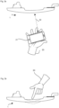
- FIGS 1a and 1b show two different views of a vehicle door handle 1, as realized according to its external design in a first exemplary embodiment of the invention.
- a handle 2 is coupled to two fastening sections 3a, 3b. With these fastening sections 3a, 3b, which are pushed through recesses in a door panel (not shown) when the vehicle door handle 1 is mounted, the door handle 1 can be fixed to the door with fasteners, so that the handle 2 remains outside the door panel and for a user is accessible.
- FIGS. 2a and 2b show the vehicle door handle in a partially transparent schematic representation. In these illustrations, the interior of the housing of the handle 2 is visible, so that the electronic functional components accommodated therein are shown.
- a circuit board 4 is accommodated in the housing of the handle 2.
- a control circuit 5 is arranged on the circuit board 4 and can be coupled to a vehicle system via lines 6.
- Near-field communication electronics 7, which has a coil 8, are also arranged on the circuit board 4.
- the coil 8 is designed as a conductor loop on the circuit board 4 and thus forms an inductance that can be used for communication in a resonant circuit of the near-field communication electronics 7.
- the near-field communication electronics are designed for communication in accordance with the NFC standard, with the resonant circuit being tuned to a frequency of approximately 13.56 MHz according to the specifications.
- metal layers 9a and 9b are applied to the inside of the housing of the handle 2. These are electrically coupled to the control device 5, which can either set the metal layers 9a and 9b to a predetermined potential or can switch them to be floating. If the control device 5 switches the metallic components 9a and 9b potential-free, the near-field communication electronics 7 are available for near-field communication under the control of the control device 5. In this communication mode, the floating metal layers 9a and 9b do not interfere with the transmission/reception operation of the coil 8 in such a way that near-field communication would be prevented.
- the transmitting/receiving operation of the coil 8 is largely prevented and the inductance of the Coil 8 is largely dependent on the distance between the metallic components 9a and 9b from the coil 8. If the handle is deformed in this sensor operation by force, in particular by tension or pressure, the distances between the metallic components 9a and 9b from the coil 8 change and thus the inductance of the coil 8 changes. This change in inductance is recognized by the control device 5 and a confirmation signal can be output to a vehicle system via lines 6.
- FIG 3a The communication mode of the device is shown schematically.
- a user 20 approaches the vehicle door handle 1 with an NFC data transporter 21, in this case a smartphone.
- the NFC data carrier 21 is located a few centimeters away from the vehicle door handle 1, data communication 22 according to the known method is under the control of the control device 5 NFC standard between the near-field communication electronics in the vehicle door handle 1 and the NFC data carrier 21 possible.
- the control device 5 switches the electrodes 9a and 9b to a predetermined potential so that further NFC communication is not possible at this time longer is possible, but the coil 8 is used inside the vehicle door handle 1 as an inductive sensor.
- the different operating modes for the coil of the near-field communication device i.e. on the one hand the communication operation and on the other hand the sensor operation, can be carried out with temporal multiplexing, alternatively Sensor operation can only be activated after successful communication.
- the metallic component can also be placed in a handle wall or on the outside of the handle. It only needs to be ensured that the metallic component is within the detection range of the coil when it is operated as an inductive sensor.
Description
Die Erfindung betrifft einen Fahrzeugtürgriff für Kraftfahrzeuge, wobei der Fahrzeugtürgriff eine Handhabe aufweist, die über einen damit gekoppelten Befestigungsabschnitt an einem Fahrzeug montierbar ist.The invention relates to a vehicle door handle for motor vehicles, wherein the vehicle door handle has a handle which can be mounted on a vehicle via a fastening section coupled thereto.
Die Handhabe des Fahrzeugtürgriffes weist ein Gehäuse auf, in dem eine Nahfeld-Kommunikationselektronik aufgenommen ist. Diese Nahfeld-Kommunikationselektronik enthält einen Schwingkreis mit einer Spule. Eine Steuerschaltung ist mit der Nahfeld-Kommunikationselektronik gekoppelt. Wenn die Steuerschaltung die Nahfeld-Kommunikationselektronik in einem Kommunikationsmodus ansteuert, wird die Spule des Schwingkreises als Sende-Empfangsspule für eine Nahfeld-Kommunikation betrieben.The handle of the vehicle door handle has a housing in which near-field communication electronics are accommodated. This near-field communication electronics contains an oscillating circuit with a coil. A control circuit is coupled to the near-field communication electronics. If the control circuit controls the near-field communication electronics in a communication mode, the coil of the resonant circuit is operated as a transmitter-receiver coil for near-field communication.
Fahrzeugtürgriffe der genannten Art sind in der Technik bekannt. Beispielsweise offenbart das Dokument
Über eine solche Nahfeld-Kommunikationselektronik können Daten zwischen einem externen Datenträger, beispielsweise einer Karte mit einem NFC-Transponder oder einem elektronischen Mobilgerät (insbesondere einem Smartphone) und der türgriffseitigen Nahfeld-Kommunikationselektronik ausgetauscht werden, sofern beide Kommunikationspartner ausreichen aneinander angenähert werden. Insbesondere für Schließfunktionen können Autorisierungsinformationen vom nahfeldkommunikationstauglichen Mobilgerät oder einem sonstigen Datenträger an das Fahrzeug übermittelt werden und in Abhängigkeit von der Überprüfung dieser Daten werden Berechtigungen und Zugriffe auf das Fahrzeug gewährt.Via such near-field communication electronics, data can be exchanged between an external data carrier, for example a card with an NFC transponder or an electronic mobile device (in particular a smartphone) and the door handle-side near-field communication electronics, provided that both communication partners are sufficiently close to one another. Particularly for locking functions, authorization information can be transmitted to the vehicle from a mobile device capable of near-field communication or another data carrier and depending on the verification This data is used to grant authorizations and access to the vehicle.
Sowohl der Aufbau von Nahfeld-Kommunikationseinrichtungen, insbesondere von NFC-Kommunikationseinrichtungen als auch deren Ansteuerungs- und Betriebsprotokolle sind bekannt. NFC ist dabei eine Sonderform von RFID (Radio-Frequency Identification), die nur über kurze Distanzen <10 cm funktioniert, eine Frequenz von 13,56MHz nutzt und verschlüsselt kommunizieren kann. Eine Nahfeldkommunikation findet immer zwischen genau zwei Teilnehmern statt. Dabei muss mindestens ein Teilnehmer ein aktives Gerät sein, im Rahmen dieser Erfindung ist die Nahfeld-Kommunikationseinrichtung im Türgriff als aktives Gerät ausgebildet. Dieses aktive Gerät erzeugt ein hochfrequentes Magnetfeld. Das andere Gerät kann ein passives Gerät sein, z.B. die Schlüsselkarte für ein Fahrzeug. Dieses Gerät benötigt keine eigene Energiequelle (es kann jedoch ohne weiteres auch ein aktives Gerät sein) sondern nur einen eigenen Schwingkreis (Antenne), der in etwa auf 13,56MHz abgestimmt ist. Das Magnetfeld des aktiven Gerätes induziert in dort eine Spannung - beide Geräte sind dann induktiv gekoppelt. Zur Datenübertragung kann ein Gerät seinen Schwingkreis variieren (Lastmodulation). Eine veränderte induktive Last registriert das aktive Gerät - es auf diese Weise Daten ausgetauscht werden. Da die Technik bekannt ist wird diesbezüglich auf die Standardisierungsvorgaben und die Fachliteratur verwiesen.Both the structure of near-field communication devices, in particular NFC communication devices, and their control and operating protocols are known. NFC is a special form of RFID (Radio-Frequency Identification), which only works over short distances <10 cm, uses a frequency of 13.56MHz and can communicate in encrypted form. Near field communication always takes place between exactly two participants. At least one participant must be an active device; within the scope of this invention, the near-field communication device in the door handle is designed as an active device. This active device generates a high-frequency magnetic field. The other device can be a passive device, e.g. the key card for a vehicle. This device does not require its own energy source (but it can easily be an active device) but only its own resonant circuit (antenna), which is tuned to approximately 13.56MHz. The magnetic field of the active device induces a voltage there - both devices are then inductively coupled. To transmit data, a device can vary its resonant circuit (load modulation). The active device registers a changed inductive load - this way data is exchanged. Since the technology is known, reference is made to the standardization specifications and the specialist literature.
Es ist den bekannten Nahfeld-Kommunikationselektroniken gemein, dass eine Spule, beispielsweise eine Drahtspule oder Leiterspule auf einer Platine, in einem Schwingkreis betrieben wird und der Datenaustausch durch Variationen der Betriebsparameter auf Sender- und Empfängerseite übermittelt werden.What is common to the known near-field communication electronics is that a coil, for example a wire coil or conductor coil on a circuit board, is operated in a resonant circuit and the data exchange is transmitted through variations of the operating parameters on the transmitter and receiver sides.
Zur Verbesserung der Kommunikation gilt grundsätzlich, dass eine Spule mit ausreichender Größe, insbesondere mit ausreichendem Spulenquerschnitt anzustreben ist, wobei dies dem sehr begrenzten Platzangebot in einem Fahrzeugtürgriff zuwiderläuft. Soll in dem Fahrzeugtürgriff außerdem noch eine Sensorik zur Erfassung von manuellen Griffbetätigungen angeordnet werden müssen häufig Kompromisse bezüglich der Ausdehnung der Kommunikationselektronik und der Sensorik bezüglich einer Griffbetätigung eingegangen werden.In order to improve communication, the basic rule is that a coil with sufficient size, in particular with a sufficient coil cross-section, should be aimed for, whereby this is: very limited space available in a vehicle door handle. If a sensor system for detecting manual handle operations is also to be arranged in the vehicle door handle, compromises often have to be made with regard to the expansion of the communication electronics and the sensors with regard to a handle operation.
Der Erfindung liegt die Aufgabe zugrunde, einen Türgriff mit verbesserter Nahfeld-Kommunikation und Erfassung der Griffbetätigung zur Verfügung zu stellen.The invention is based on the object of providing a door handle with improved near-field communication and detection of handle operation.
Diese Aufgabe wird durch einen Fahrzeugtürgriff mit den Merkmalen des Patentanspruches 1 sowie ein Verfahren mit den Merkmalen des Patentanspruches 6 gelöst.This object is achieved by a vehicle door handle with the features of
Der erfindungsgemäße Fahrzeugtürgriff der eingangs genannten Art sieht vor, über die Steuerschaltung die Nahfeld-Kommunikationselektronik oder Bestandteile dieser Nahfeld-Kommunikationselektronik, welche zumindest die Spule enthalten, in einem weiteren Betriebsmodus, nämlich einem Sensormodus anzusteuern. Während der Betrieb der Nahfeld-Kommunikationselektronik und der zugeordneten Spule im Kommunikationsmodus als Sende-Empfangseinrichtung bekannt ist, kann dieser Kommunikationsmodus erfindungsgemäß deaktiviert werden und die Spule der Nahfeld-Kommunikationselektronik kann im Sensormodus als induktiver Sensor angesteuert werden. Dazu ist im Bereich der Spule, beispielsweise im Bereich einer Projektion des Spulenquerschnittes auf das Innere des umgebenden Gehäuses, senkrecht zu der Spulenachse, ein metallisches Bauteil angeordnet. Das metallische Bauteil ist dabei mit dem Gehäuse der Handhabe gekoppelt, so dass es bei Verformung des Gehäuses bewegbar ist. Greift ein Benutzer auf die Handhabe zu und übt eine Kraft auf die Handhabe aus, so wird eine geringfügige Verformung des Gehäuses bewirkt und damit das metallische Bauteil im Inneren des Gehäuses bewegt, während die Spule ortsfest im Griff verbleibt. Diese relative Lageänderung des metallischen Bauteils gegenüber der Spule der Nahfeld-Kommunikationselektronik kann als Sensorsignal ausgewertet werden, sofern die Induktivität der Spule überwacht wird. Dazu nimmt in diesem Sensormodus, in welchem die Induktivität zur Erfassung von Verformungen des Gehäuses betrieben wird, die Steuerschaltung wiederholt Messungen der Induktivität der Spule vor und kann so Verformungen des Gehäuses erfassen. In Abhängigkeit von den erfassten Induktivitätswerten erzeugt die Steuerschaltung ein Betätigungssignal, welches auf eine Betätigung des Fahrzeugtürgriffes durch manuelle Manipulation durch einen Benutzer hinweist.The vehicle door handle according to the invention of the type mentioned at the beginning provides for the near-field communication electronics or components of this near-field communication electronics, which at least contain the coil, to be controlled via the control circuit in a further operating mode, namely a sensor mode. While the operation of the near-field communication electronics and the associated coil in the communication mode is known as a transceiver device, this communication mode can be deactivated according to the invention and the coil of the near-field communication electronics can be controlled as an inductive sensor in the sensor mode. For this purpose, a metallic component is arranged in the area of the coil, for example in the area of a projection of the coil cross section onto the interior of the surrounding housing, perpendicular to the coil axis. The metallic component is coupled to the housing of the handle so that it can be moved when the housing is deformed. If a user accesses the handle and exerts a force on the handle, a slight deformation of the housing is caused and the metallic component inside the housing is moved while the coil remains stationary in the handle. This relative change in position of the metallic component relative to the coil of the near-field communication electronics can be evaluated as a sensor signal if the inductance of the coil is monitored. For this purpose, in this sensor mode, in which the inductance is operated to detect deformations of the housing, the control circuit repeatedly takes measurements of the inductance of the coil and can thus detect deformations of the housing. Depending on the detected inductance values, the control circuit generates an actuation signal which indicates an actuation of the vehicle door handle by manual manipulation by a user.
Ein und dieselbe Spule wird gemäß der Erfindung also einerseits in einem Kommunikationsmodus als Sende-/Empfangsspule für eine Nahfeld-Kommunikation verwendet und in einem anderen Modus, in welchem der Kommunikationsmodus zeitweise ausgeschaltet ist, wird die Spule als induktiver Sensor betrieben, in welchem die Induktivität der Spule wiederholt gemessen wird. Die Art der Messung der Induktivität kann beliebig erfolgen, beispielsweise durch Frequenzkontrolle des Schwingkreises.According to the invention, one and the same coil is used in one communication mode as a transmitting/receiving coil for near-field communication and in another mode, in which the communication mode is temporarily switched off, the coil is operated as an inductive sensor in which the inductance the coil is measured repeatedly. The way the inductance can be measured can be done in any way, for example by controlling the frequency of the resonant circuit.
Die beiden Betriebsmodi, einerseits der Kommunikationsmodus und andererseits der Sensormodus, können zeitlich wiederholt abwechselnd aktiviert werden (zeitliches Multiplexen), es kann jedoch auch vorgesehen sein, dass der Sensormodus erst aktiviert wird, wenn eine erfolgreiche Legitimationsprüfung über eine Nahfeld-Kommunikation durchgeführt wurde. Greift also beispielsweise ein Benutzer auf ein Fahrzeug zu und legitimiert sich mit einem Datenträger über Nahfeld-Kommunikation unter Kommunikationswirkung der Einrichtung im Türgriff, kann nachfolgend der Kommunikationsmodus deaktiviert werden und der Sensormodus aktiviert werden, um eine anschließende händische Betätigung des Benutzers am Fahrzeugtürgriff zu erfassen.The two operating modes, on the one hand the communication mode and on the other hand the sensor mode, can be activated repeatedly and alternately over time (time multiplexing), but it can also be provided that the sensor mode is only activated when a successful authentication check has been carried out via near-field communication. For example, if a user accesses a vehicle and authenticates himself with a data carrier via near-field communication under the communication effect of the device in the door handle, the communication mode can subsequently be deactivated and the sensor mode activated in order to detect a subsequent manual operation by the user on the vehicle door handle.
Vorzugsweise ist das metallische Bauteil eine auf der Gehäuseinnenseite aufgebrachte metallische Schicht. Eine solche metallische Schicht kann durch Aufsprühen eines metallischen Lacks oder Anbringung einer entsprechenden Folierung oder Aufkleben eines metallischen Bleches gebildet werden. Eine solche Schicht ist auf der Innenseite des Gehäuses keiner mechanischen Abnutzung oder Umwelteinflüssen ausgesetzt und ist einfach zu montieren und günstig in der Herstellung.The metallic component is preferably a metallic layer applied to the inside of the housing. Such a metallic layer can be created by spraying on a metallic Paint or attaching an appropriate foil or gluing on a metallic sheet can be formed. Such a layer on the inside of the housing is not exposed to mechanical wear or environmental influences and is easy to assemble and inexpensive to manufacture.
In einer bevorzugten Gestaltung der Erfindung ist die Spule auf einer im Gehäuse angeordneten Platine als Leiterschleife ausgebildet.In a preferred embodiment of the invention, the coil is designed as a conductor loop on a circuit board arranged in the housing.
Eine solche Ausbildung der Spule als Leiterbahn auf einer Platine stellt bei ortsfester und verschiebesicherer Anordnung der Platine im Gehäuse des Fahrzeugtürgriffes sicher, dass die Spule jederzeit in einer definierten und reproduzierbaren Ausrichtung und Position im Inneren der Handhabe aufgenommen ist. Außerdem ist die Fertigung einer solchen Spule als Bestandteil der Leiterbahnen einer gefertigten Platine besonders kostengünstig.Such a design of the coil as a conductor track on a circuit board ensures that the circuit board is arranged in a stationary and non-displaceable manner in the housing of the vehicle door handle that the coil is always accommodated in a defined and reproducible orientation and position inside the handle. In addition, the production of such a coil as part of the conductor tracks of a manufactured circuit board is particularly cost-effective.
In einer vorteilhaften Ausgestaltung der Erfindung ist die Steuerschaltung mit dem metallischen Bauteil elektrisch gekoppelt und derart ausgebildet, dass sie das metallische Bauteil im Sensorbetrieb, also bei Betrieb der Nahfeld-Kommunikationseinrichtung im Sensormodus, auf ein erstes elektrisches Potenzial legt.In an advantageous embodiment of the invention, the control circuit is electrically coupled to the metallic component and designed in such a way that it sets the metallic component to a first electrical potential in sensor operation, i.e. when the near-field communication device is operated in sensor mode.
Die Steuerschaltung ist über ansteuerbare Komponenten so mit dem metallischen Bauteil gekoppelt, dass eine Vorgabe eines elektrischen Potenzials für das metallische Bauteil über die Steuerschaltung möglich ist. Bei Potenzialvorgabe für des metallische Bauteil wird die Beeinflussung der Induktivität der Spule durch das potenzialfeste metallische Bauteil deutlich erhöht, so dass Lageveränderungen des metallischen Bauteils gegenüber der Spule besser detektiert werden können. Die Potenzialvorgabe bewirkt eine deutliche Modifikation der Feldlinien des Spulenfeldes gegenüber einem metallischen Bauteil ohne Potenzialvorgabe (floating).The control circuit is coupled to the metallic component via controllable components in such a way that an electrical potential for the metallic component can be specified via the control circuit. When the potential is specified for the metallic component, the influence on the inductance of the coil by the potential-proof metallic component is significantly increased, so that changes in position of the metallic component relative to the coil can be better detected. The potential specification causes a significant modification of the field lines of the coil field compared to a metallic component without potential specification (floating).
Es ist besonders bevorzugt, wenn bei dem Fahrzeugtürgriff der vorstehend genannten Art die Steuerschaltung außerdem so ausgebildet ist, dass sie das metallische Bauteil bei Betrieb der Nahfeld-Kommunikationseinrichtung im Kommunikationsmodus ohne Potenzialvorgabe betreibt. Das Betreiben ohne Potenzialvorgabe bedeutet, dass eine Entkopplung des metallischen Bauteils von Bezugspotenzialen und Betriebspotenzialen, also mit float-Potenzial erfolgt. Allgemein ist unter float-Potenzial zu verstehen, dass keine definierte Potenzialbeziehung des metallischen Bauteils gegenüber übrigen Komponenten vorliegt und insbesondere keine galvanische Kopplung mit Masse oder Betriebsspannungen erfolgt. Die Spule der Nahfeld-Kommunikationselektronik wird bei einer potenzialfreien Schaltung (also bei undefiniertem Potenzial des metallischen Bauteils) in ihrem Sende-Empfangsbetrieb durch das metallische Bauteil nur geringfügig gestört. Das Spulenfeld kann sich aufgrund der Potenzialfreiheit des metallischen Bauteils in ausreichender Weise in den Bereich vor der Spule und in den Außenbereich der Handhabe ausdehnen und auf diese Weise für die Nahfeld-Kommunikation zur Verfügung stehen.It is particularly preferred if, in the vehicle door handle of the type mentioned above, the control circuit is also designed such that it operates the metallic component when the near-field communication device is operated in the communication mode without a potential specification. Operating without a potential specification means that the metallic component is decoupled from reference potentials and operating potentials, i.e. with float potential. In general, float potential means that there is no defined potential relationship between the metallic component and other components and, in particular, there is no galvanic coupling to ground or operating voltages. With a potential-free circuit (i.e. with an undefined potential of the metallic component), the coil of the near-field communication electronics is only slightly disturbed in its transmitting and receiving operation by the metallic component. Due to the potential-free nature of the metallic component, the coil field can extend sufficiently into the area in front of the coil and into the outside area of the handle and in this way be available for near-field communication.
Gemäß dieser Gestaltung der Erfindung wird im Sensormodus ein Potenzial des metallischen Bauteils vorgegeben, im Kommunikationsmodus wird jedoch das metallische Bauteil potenzialfrei gelegt. Damit wird das metallische Bauteil zu einem ansteuerbaren Bestandteil und die Wirksamkeit insbesondere des Sensormodus erhöhenden Bauteils.According to this design of the invention, a potential of the metallic component is specified in the sensor mode, but in the communication mode the metallic component is made potential-free. The metallic component thus becomes a controllable component and a component that increases the effectiveness of the sensor mode in particular.
Das erfindungsgemäße Verfahren wirkt analog zu der vorgenannten Einrichtung. Es wird unter Verwendung eines Fahrzeugtürgriffes mit Nahfeld-Kommunikationseinrichtung die Spule der Nahfeld-Kommunikationselektronik in der üblichen Weise zur Nahfeld-Kommunikation eingesetzt oder, in zeitlichem Wechsel, als Sensoreinrichtung mit der Spule als induktivem Sensor. Dabei wird die Induktivität der Spule wiederholt gemessen und Änderungen der Induktivität können auf eine Betätigung der Handhabe des Fahrzeugtürgriffes hindeuten, da dann das Gehäuse der Handhabe verformt wird und ein mit der Handhabe gekoppeltes metallisches Bauteil in seiner Lage gegenüber der Spule verändert wird. Diese Lageveränderung führt zu detektierbaren Veränderungen der Induktivität der Spule und mit dem Verfahren kann dann ein und dieselbe Einrichtung mit derselben Spule sowohl zur Nahfeld-Kommunikation als auch als induktiver Sensor verwendet werden.The method according to the invention works analogously to the aforementioned device. Using a vehicle door handle with a near-field communication device, the coil of the near-field communication electronics is used in the usual way for near-field communication or, alternating over time, as a sensor device with the coil as an inductive sensor. The inductance of the coil is measured repeatedly and changes in inductance can be attributed to a Actuation of the handle of the vehicle door handle indicates that the housing of the handle is then deformed and a metallic component coupled to the handle is changed in its position relative to the coil. This change in position leads to detectable changes in the inductance of the coil and with the method one and the same device with the same coil can then be used both for near-field communication and as an inductive sensor.
Die Erfindung wird nun anhand der beiliegenden Zeichnungen näher erläutert.The invention will now be explained in more detail with reference to the accompanying drawings.
Die
-
Figur 1b zeigt den Fahrzeugtürgriff ausFigur 1a in einer zweiten Ansicht; -
Figur 2a zeigt eine schematische Schnittansicht des Fahrzeugtürgriffes ausFigur 1a ; -
Figur 2b zeigt eine schematische teiltransparente Ansicht des Fahrzeugtürgriffes ausFigur 1b ; -
Figur 3a -
Figur 3b
-
Figure 1b shows the vehicle door handleFigure 1a in a second view; -
Figure 2a shows a schematic sectional view of the vehicle door handleFigure 1a ; -
Figure 2b shows a schematic, partially transparent view of the vehicle door handleFigure 1b ; -
Figure 3a shows schematically the use of the first embodiment in a communication mode; -
Figure 3b shows schematically the use of the first embodiment in a sensor mode.
Die
Zu beiden Seiten von der Nahfeld-Kommunikationselektronik 7 und damit auch zu beiden Seiten von der Spule 8 sind auf der Innenseite des Gehäuses der Handhabe 2 Metallschichten 9a und 9b aufgebracht. Diese sind elektrisch mit der Steuereinrichtung 5 gekoppelt, welche die Metallschichten 9a und 9b entweder auf ein vorgegebenes Potenzial legen kann oder potenzialfrei (floating) schalten kann. Schaltet die Steuereinrichtung 5 die metallischen Bauteile 9a und 9b potenzialfrei, steht die Nahfeld-Kommunikationselektronik 7 unter Steuerung der Steuereinrichtung 5 zur Nahfeld-Kommunikation zur Verfügung. In diesem Kommunikationsmodus stören die potenzialfreien Metallschichten 9a und 9b den Sende-/Empfangsbetrieb der Spule 8 nicht in einer Weise, dass die Nahfeld-Kommunikation unterbunden würde. Werden die metallischen Bauteile 9a und 9b jedoch mit einem vorgegebenen Potenzial belegt, was unter Steuerung der Steuereinrichtung 5 erfolgt, um die Vorrichtung in den Sensorbetrieb zu versetzen, so wird der Sende-Empfangsbetrieb der Spule 8 weitgehend unterbunden und die Induktivität der Spule 8 ist maßgeblich von dem Abstand der metallischen Bauteile 9a und 9b von der Spule 8 abhängig. Wird die Handhabe in diesem Sensorbetrieb durch Krafteinwirkung verformt, insbesondere durch Zug oder Druck, ändern sich die Abstände der metallischen Bauteile 9a und 9b zu der Spule 8 und damit ändert sich die Induktivität der Spule 8. Diese Änderung der Induktivität wird von der Steuereinrichtung 5 erkannt und es kann ein Bestätigungssignal über die Leitungen 6 an ein Fahrzeugsystem ausgegeben werden.On both sides of the near-
In
Die verschiedenen Betriebsmodi für die Spule der Nahfeld-Kommunikationseinrichtung, also einerseits der Kommunikationsbetrieb und andererseits der Sensorbetrieb, können mit zeitlichem Multiplexing ausgeführt werden, alternativ kann der Sensorbetrieb auch erst nach erfolgreicher Kommunikation aktiviert werden.The different operating modes for the coil of the near-field communication device, i.e. on the one hand the communication operation and on the other hand the sensor operation, can be carried out with temporal multiplexing, alternatively Sensor operation can only be activated after successful communication.
Während die Anordnung des metallischen Bauteils im inneren des Griffes im vorstehenden Beispiel beschrieben wurde, kann das metallische Bauteil auch in einer Griffwandung oder an der Außenseite des Griffes platziert sein. Es muss lediglich sichergestellt sein, dass das metallische Bauteil im Erfassungsbereich der Spule liegt, wenn diese als induktiver Sensor betrieben wird.While the arrangement of the metallic component inside the handle was described in the above example, the metallic component can also be placed in a handle wall or on the outside of the handle. It only needs to be ensured that the metallic component is within the detection range of the coil when it is operated as an inductive sensor.
Claims (10)
- Vehicle door handle (1) with a grip section (2) and at least one fastening section coupled to the grip section (2) for mounting the grip section (2) on a vehicle,wherein the grip section (2) has a housing and near-field communication electronics accommodated in the housing, wherein the grip section (2) is designed such that the housing is deformed when it is actuated, wherein the near-field communication electronics (7) has an oscillating circuit with a coil (8) and wherein a control circuit (5) is coupled to the near-field communication electronics,wherein the control circuit (5) is designed to control the near-field communication electronics in a communication mode, wherein the coil (8) can be operated as a transmit/receive coil (8) for near-field communication,wherein the housing has at least one metallic component (9a, 9b) in a region which faces the coil (8), wherein the metallic component is designed to change its position relative to the coil (8) when the housing is deformed,wherein the control circuit (5) is designed for temporarily deactivating the communication mode and for activating the coil (8) in a sensor mode, wherein the control circuit (5) is designed to repeatedly measure the inductance of the coil (8) in the sensor mode in order to detect deformations of the housing,wherein the control circuit (5) is designed to provide an actuation signal as a function of the inductance of the coil (8) when the coil (8) is controlled in sensor mode.
- Vehicle door handle (1) according to claim 1, wherein the metallic component (9a, 9b) is a metallic layer applied to the inside or outside of the housing.
- Vehicle door handle (1) according to one of the preceding claims, wherein the coil (8) is formed as a conductor loop on a circuit board arranged in the housing.
- Vehicle door handle (1) according to one of the preceding claims, wherein the control circuit (5) is electrically coupled to the metallic component (9a, 9b) and is designed in such a way that it contacts the metallic component to a first electrical potential during operation of the near-field communication device in the sensor mode.
- Vehicle door handle (1) according to claim 4, wherein the control circuit (5) is designed in such a way that it makes the metallic component (9a, 9b) potential-free, floating, during operation of the near-field communication device in the communication mode.
- Method for near-field communication and detection of actuations on a vehicle door handle (1) with a grip section (2) and at least one fastening section coupled to the grip section (2) for mounting the grip section (2) on a vehicle,wherein the grip section (2) has a housing and a near-field communication electronics unit accommodated in the housing, wherein the housing is deformed when the handle is actuated, wherein the near-field communication electronics unit has an oscillating circuit with a coil (8) and wherein a control circuit (5) is coupled to the near-field communication electronics unit,wherein the near-field communication electronics are operated in a communication mode in which the coil (8) is operated as a transmitting/receiving coil (8) for carrying out near-field communication under control of the control circuit (5), wherein a metallic component is coupled to the housing in a region which is opposite the coil (8), so that the metallic component is moved relative to the coil (8) when the housing is deformed,wherein the control circuit (5) temporarily deactivates the communication mode and controls the coil (8) in a sensor mode, wherein the control circuit repeatedly measures the inductance of the coil (8) in order to detect deformations of the housing,wherein the control circuit (5) provides an actuation signal as a function of the inductance of the coil (8).
- Method according to claim 6, wherein a metallic layer is applied to the inside of the housing as a metallic component.
- Method according to one of claims 6 or 7, wherein the coil (8) is a printed circuit board arranged in the housing as a conductor loop.
- Method according to one of claims 6 to 8, wherein the control circuit (5) is coupled to the metallic component and the metallic component is applied to a first electrical potential when the near-field communication device is operating in the sensor mode.
- Method according to one of claims 6 to 9, wherein the control circuit (5) sets the metallic component to float potential, potential-free, during operation of the near-field communication device in the communication mode.
Applications Claiming Priority (1)
| Application Number | Priority Date | Filing Date | Title |
|---|---|---|---|
| DE102018125922.0A DE102018125922A1 (en) | 2018-10-18 | 2018-10-18 | Vehicle door handle with near-field communication electronics |
Publications (2)
| Publication Number | Publication Date |
|---|---|
| EP3640896A1 EP3640896A1 (en) | 2020-04-22 |
| EP3640896B1 true EP3640896B1 (en) | 2024-02-14 |
Family
ID=67439072
Family Applications (1)
| Application Number | Title | Priority Date | Filing Date |
|---|---|---|---|
| EP19188577.1A Active EP3640896B1 (en) | 2018-10-18 | 2019-07-26 | Vehicle door handle with near field communication electronics |
Country Status (2)
| Country | Link |
|---|---|
| EP (1) | EP3640896B1 (en) |
| DE (1) | DE102018125922A1 (en) |
Family Cites Families (2)
| Publication number | Priority date | Publication date | Assignee | Title |
|---|---|---|---|---|
| DE102013102701A1 (en) | 2013-03-18 | 2014-09-18 | Huf Hülsbeck & Fürst Gmbh & Co. Kg | Door handle assembly for a motor vehicle with capacitive proximity sensor and NFC transmitter / receiver unit |
| WO2017009073A1 (en) * | 2015-07-13 | 2017-01-19 | Huf Hülsbeck & Fürst Gmbh & Co. Kg | Exterior door handle for a vehicle |
-
2018
- 2018-10-18 DE DE102018125922.0A patent/DE102018125922A1/en active Pending
-
2019
- 2019-07-26 EP EP19188577.1A patent/EP3640896B1/en active Active
Non-Patent Citations (1)
| Title |
|---|
| MEINKE H: "Sensor-Messtechnik", 1 October 2012 (2012-10-01), pages 1 - 11, XP055835772, Retrieved from the Internet <URL:https://mb-bachelor.htw-berlin.de/files/Stg/MB/Versuchsanleitungen_Messtechnik/Sensor.pdf> [retrieved on 20210830] * |
Also Published As
| Publication number | Publication date |
|---|---|
| DE102018125922A1 (en) | 2020-04-23 |
| EP3640896A1 (en) | 2020-04-22 |
Similar Documents
| Publication | Publication Date | Title |
|---|---|---|
| DE10148830B4 (en) | Method and system for authenticating a first transceiver to a remotely located second transceiver | |
| EP2256662B1 (en) | Method for detecting identification media | |
| DE102014218213B4 (en) | Arrangement and method for detecting the approach of an object | |
| EP2197714B1 (en) | Flexible key detection for passive access and driver authorization systems | |
| EP0993397A1 (en) | Keyless device for controlling access to automobiles and keyless method for checking access authorisation | |
| DE102005035935A1 (en) | Motor vehicle door handle, has capacitors whose capacitance is selected such that influence of interfering signal at supply line in capacitance of sensor is reduced without interfering transmission of high frequency signals through coil | |
| EP2125449B1 (en) | Method for the characterization of the distance in inductively coupled access systems for vehicles | |
| DE102011117978A1 (en) | Locking system, in particular for a motor vehicle | |
| EP3261060B1 (en) | Methods for controlling access in an access control system for persons or vehicles and access control system | |
| WO2003069538A1 (en) | Switching device actuated with a transponder | |
| EP1496174A2 (en) | Non-contact sensor arrangement for the opening of a vehicle door and a method for unlocking a vehicle door | |
| EP1723615B1 (en) | Inductive component for an electronic key | |
| DE102007058278A1 (en) | Seat e.g. child seat, belt system for use in motor vehicle, has reader arranged on transponder, and recognizing pre-determined influence of transponder or presence and absence of transponder that is coupled to component of system | |
| DE102014226925A1 (en) | Method and device for access verification in a vehicle | |
| EP1083280B1 (en) | Keyless actuating and/or locking device, particularly for vehicles | |
| DE10222186C1 (en) | Safety switch has comparator providing switch signal if energy induced in receiver element during period following electromagnetic signal emission exceeds/falls below predefined threshold | |
| EP3640896B1 (en) | Vehicle door handle with near field communication electronics | |
| DE102014221933B4 (en) | Preventing a malfunction of a keyless access authorization system of a motor vehicle by the alternating field of an inductive charging station | |
| DE102007058277A1 (en) | The vehicle occupant protection device | |
| DE102015222235B4 (en) | Portable device and method for activating or deactivating a motor vehicle | |
| DE19859344A1 (en) | Control of a security system within a road vehicle using a number of directional signals transmitted by a unit carried by driver | |
| DE102013110017A1 (en) | Apparatus and method for classification and identification with an RFID reader | |
| DE10326676B4 (en) | Control device for a motor vehicle transmission and motor vehicle transmission | |
| DE102020126533A1 (en) | UWB module unit for a vehicle | |
| DE102004038837B4 (en) | Electronic anti-theft system with correlated transmit / receive antennas |
Legal Events
| Date | Code | Title | Description |
|---|---|---|---|
| PUAI | Public reference made under article 153(3) epc to a published international application that has entered the european phase |
Free format text: ORIGINAL CODE: 0009012 |
|
| STAA | Information on the status of an ep patent application or granted ep patent |
Free format text: STATUS: THE APPLICATION HAS BEEN PUBLISHED |
|
| AK | Designated contracting states |
Kind code of ref document: A1 Designated state(s): AL AT BE BG CH CY CZ DE DK EE ES FI FR GB GR HR HU IE IS IT LI LT LU LV MC MK MT NL NO PL PT RO RS SE SI SK SM TR |
|
| AX | Request for extension of the european patent |
Extension state: BA ME |
|
| STAA | Information on the status of an ep patent application or granted ep patent |
Free format text: STATUS: REQUEST FOR EXAMINATION WAS MADE |
|
| 17P | Request for examination filed |
Effective date: 20200603 |
|
| RBV | Designated contracting states (corrected) |
Designated state(s): AL AT BE BG CH CY CZ DE DK EE ES FI FR GB GR HR HU IE IS IT LI LT LU LV MC MK MT NL NO PL PT RO RS SE SI SK SM TR |
|
| STAA | Information on the status of an ep patent application or granted ep patent |
Free format text: STATUS: EXAMINATION IS IN PROGRESS |
|
| 17Q | First examination report despatched |
Effective date: 20210907 |
|
| GRAP | Despatch of communication of intention to grant a patent |
Free format text: ORIGINAL CODE: EPIDOSNIGR1 |
|
| STAA | Information on the status of an ep patent application or granted ep patent |
Free format text: STATUS: GRANT OF PATENT IS INTENDED |
|
| RIC1 | Information provided on ipc code assigned before grant |
Ipc: H04B 5/00 20060101ALI20230926BHEP Ipc: H01Q 1/32 20060101ALI20230926BHEP Ipc: H03K 17/97 20060101ALI20230926BHEP Ipc: E05B 81/76 20140101ALI20230926BHEP Ipc: G07C 9/00 20200101AFI20230926BHEP |
|
| INTG | Intention to grant announced |
Effective date: 20231013 |
|
| GRAS | Grant fee paid |
Free format text: ORIGINAL CODE: EPIDOSNIGR3 |
|
| GRAA | (expected) grant |
Free format text: ORIGINAL CODE: 0009210 |
|
| STAA | Information on the status of an ep patent application or granted ep patent |
Free format text: STATUS: THE PATENT HAS BEEN GRANTED |
|
| AK | Designated contracting states |
Kind code of ref document: B1 Designated state(s): AL AT BE BG CH CY CZ DE DK EE ES FI FR GB GR HR HU IE IS IT LI LT LU LV MC MK MT NL NO PL PT RO RS SE SI SK SM TR |
|
| P01 | Opt-out of the competence of the unified patent court (upc) registered |
Effective date: 20240105 |
|
| REG | Reference to a national code |
Ref country code: GB Ref legal event code: FG4D Free format text: NOT ENGLISH |
|
| REG | Reference to a national code |
Ref country code: CH Ref legal event code: EP |
|
| REG | Reference to a national code |
Ref country code: DE Ref legal event code: R096 Ref document number: 502019010570 Country of ref document: DE |
|
| REG | Reference to a national code |
Ref country code: IE Ref legal event code: FG4D Free format text: LANGUAGE OF EP DOCUMENT: GERMAN |