EP3640767A1 - Verfahren zum bestimmen mindestens eines bereichs in mindestens einem eingabemodell für mindestens ein zu platzierendes element - Google Patents
Verfahren zum bestimmen mindestens eines bereichs in mindestens einem eingabemodell für mindestens ein zu platzierendes element Download PDFInfo
- Publication number
- EP3640767A1 EP3640767A1 EP18200985.2A EP18200985A EP3640767A1 EP 3640767 A1 EP3640767 A1 EP 3640767A1 EP 18200985 A EP18200985 A EP 18200985A EP 3640767 A1 EP3640767 A1 EP 3640767A1
- Authority
- EP
- European Patent Office
- Prior art keywords
- area
- placement
- input model
- input
- determining
- Prior art date
- Legal status (The legal status is an assumption and is not a legal conclusion. Google has not performed a legal analysis and makes no representation as to the accuracy of the status listed.)
- Granted
Links
Images

Classifications
-
- G—PHYSICS
- G06—COMPUTING OR CALCULATING; COUNTING
- G06F—ELECTRIC DIGITAL DATA PROCESSING
- G06F3/00—Input arrangements for transferring data to be processed into a form capable of being handled by the computer; Output arrangements for transferring data from processing unit to output unit, e.g. interface arrangements
- G06F3/01—Input arrangements or combined input and output arrangements for interaction between user and computer
- G06F3/011—Arrangements for interaction with the human body, e.g. for user immersion in virtual reality
-
- G—PHYSICS
- G06—COMPUTING OR CALCULATING; COUNTING
- G06T—IMAGE DATA PROCESSING OR GENERATION, IN GENERAL
- G06T19/00—Manipulating three-dimensional [3D] models or images for computer graphics
- G06T19/20—Editing of three-dimensional [3D] images, e.g. changing shapes or colours, aligning objects or positioning parts
-
- G—PHYSICS
- G06—COMPUTING OR CALCULATING; COUNTING
- G06F—ELECTRIC DIGITAL DATA PROCESSING
- G06F3/00—Input arrangements for transferring data to be processed into a form capable of being handled by the computer; Output arrangements for transferring data from processing unit to output unit, e.g. interface arrangements
- G06F3/01—Input arrangements or combined input and output arrangements for interaction between user and computer
- G06F3/011—Arrangements for interaction with the human body, e.g. for user immersion in virtual reality
- G06F3/013—Eye tracking input arrangements
-
- G—PHYSICS
- G06—COMPUTING OR CALCULATING; COUNTING
- G06F—ELECTRIC DIGITAL DATA PROCESSING
- G06F3/00—Input arrangements for transferring data to be processed into a form capable of being handled by the computer; Output arrangements for transferring data from processing unit to output unit, e.g. interface arrangements
- G06F3/01—Input arrangements or combined input and output arrangements for interaction between user and computer
- G06F3/017—Gesture based interaction, e.g. based on a set of recognized hand gestures
-
- G—PHYSICS
- G06—COMPUTING OR CALCULATING; COUNTING
- G06F—ELECTRIC DIGITAL DATA PROCESSING
- G06F30/00—Computer-aided design [CAD]
-
- G—PHYSICS
- G06—COMPUTING OR CALCULATING; COUNTING
- G06F—ELECTRIC DIGITAL DATA PROCESSING
- G06F30/00—Computer-aided design [CAD]
- G06F30/10—Geometric CAD
- G06F30/13—Architectural design, e.g. computer-aided architectural design [CAAD] related to design of buildings, bridges, landscapes, production plants or roads
-
- G—PHYSICS
- G06—COMPUTING OR CALCULATING; COUNTING
- G06T—IMAGE DATA PROCESSING OR GENERATION, IN GENERAL
- G06T2200/00—Indexing scheme for image data processing or generation, in general
- G06T2200/24—Indexing scheme for image data processing or generation, in general involving graphical user interfaces [GUIs]
-
- G—PHYSICS
- G06—COMPUTING OR CALCULATING; COUNTING
- G06T—IMAGE DATA PROCESSING OR GENERATION, IN GENERAL
- G06T2210/00—Indexing scheme for image generation or computer graphics
- G06T2210/04—Architectural design, interior design
-
- G—PHYSICS
- G06—COMPUTING OR CALCULATING; COUNTING
- G06T—IMAGE DATA PROCESSING OR GENERATION, IN GENERAL
- G06T2219/00—Indexing scheme for manipulating 3D models or images for computer graphics
- G06T2219/20—Indexing scheme for editing of 3D models
- G06T2219/2004—Aligning objects, relative positioning of parts
Definitions
- the invention relates to a computer-implemented method for determining at least one area in at least one input model for at least one element to be placed. Furthermore, the invention is directed to a corresponding computing unit and computer program product. The invention can be located in particular in the technical field of building equipment.
- Virtual Reality or also called Virtual Reality (VR)
- VR Virtual Reality
- Virtual reality describes the representation of a virtual world that is computer-generated.
- the virtual world can be based on the real world.
- virtual reality is closely related to VR glasses. Thanks to the use of VR glasses, the user is no longer dependent on the monitor, but has a 3D image available and can comfortably turn his head in all directions to follow the virtual world.
- the user can also perceive a building plan in three dimensions.
- this building plan fire alarm devices or other elements to be placed often have to be placed afterwards. Accordingly, it is often necessary to change the building plan, such as adding an element.
- the installation or placement of an element to be placed in the building plan carried out manually by a specialist.
- the specialist must ensure in a complex and time-consuming manner that certain rules, standards and / or boundary conditions are met.
- the fire detector must keep a certain distance from a wall, etc., see below.
- the specialist places the element to be placed manually in several runs.
- the rules, standards or boundary conditions must be checked and fulfilled.
- the building plan is then checked and approved by a certifying body.
- the present invention therefore sets itself the objective technical task of providing a method for determining at least one area in at least one input model for at least one element to be placed, which is more reliable and efficient.
- the invention is directed to a method for determining at least a region of an input model for an element to be placed.
- an input data record is received.
- the input data record comprises at least the element to be placed, the multiplicity of conditions and an input model.
- the element to be placed is the element that is placed using the method.
- Exemplary elements are elements of a building, in particular a building, such as fire detectors and smoke detectors.
- Other other exemplary elements are sensors and actuators. This can be a new element or an existing element. For example, a new element or other element can be placed for the first time or placed again.
- the conditions can also be called specifications. They must be taken into account when placing the element to be placed in an area of the input model.
- the element to be placed may only be placed in certain areas of the input model that meet the conditions. In other words, the placing element cannot be placed anywhere.
- the term placement can also be interpreted as setting up or installing.
- Exemplary conditions are rules and standards, such as distance rules for smoke detectors or fire detectors, reachability criteria for manual detectors, visibility criteria for visual warning devices, etc.
- distance rules fire detectors, for example, must be a certain distance from the wall or sockets a certain distance from the floor. This distance can also be viewed as a minimum distance.
- the detection areas all fire detectors in a room cover the floor area of the room, etc.
- the input model can be designed two-dimensionally or three-dimensionally.
- the three-dimensional digital model is a computer-generated CAD or ifc model in which the building is geometrically visualized as a virtual model.
- the parts of the building are preferably semantically annotated.
- the input model can be presented to a user, in particular through virtual reality (VR) or augmented reality (AR) glasses. Alternatively, other display units can be used.
- VR has proven to be advantageous in terms of planning a new building, as there is no real building yet.
- AR can advantageously be used in existing buildings, with the virtual world being visually superimposed on the real world.
- one or more conditions are selected which are related to or can be associated with the element to be placed.
- the conditions regarding the placement area can differ, such as by region, country, state, canton, etc.
- the conditions can differ with regard to the building type, such as office buildings, hospitals, airports, residential buildings, warehouses, etc.
- the conditions can vary with regard to space - or differentiate between room types, such as office rooms, kitchens, washrooms, storage rooms, etc.
- the applicable rules are selected for the element to be placed and taken into account in the next step.
- the at least one valid and / or invalid area of the input model is determined as a function of the at least one associated condition.
- the associated condition is applied to the input model.
- the valid and invalid ranges can be determined based on the associated condition.
- the areas are, in particular, partial areas of the input model or the underlying unit.
- the underlying unit can be the building above.
- the valid areas can also be referred to as permissible areas in which the element to be placed should be placed. Referring to the above example of a fire detector, the method according to the invention determines that part of the building in which the fire detector fulfills the condition of the minimum distance from the walls and / or other conditions.
- the advantage is that the method according to the invention for determining at least one area of an input model for an element to be placed, as well as further steps of the placement, is carried out efficiently or independently by a computing unit. This saves specialists with expert know-how and time. Furthermore, the computing unit is advantageously less prone to errors and thus more reliable. As a result, the costs caused, for example, by possible later corrections can be avoided or at least considerably reduced.
- the process allows existing building plans to be flexibly and dynamically adapted without the need for expert knowledge or other components.
- the building plan can therefore be expanded by non-experts at any time, as direct visual feedback is given about the conformity with the rules. This significantly improves the adaptability and response time to changes.
- the method further comprises displaying the at least one valid area and / or the at least one invalid area, in particular by means of virtual reality (VR) or augmented reality (AR) glasses or another display unit.
- the input model is presented to the user, in particular by means of virtual reality (VR) or augmented reality (AR) glasses, as described above.
- other data can also be displayed to the user.
- the specific area can be displayed to the user in color.
- the user can determine the location or the location of the placement in the valid area by looking in his direction and carry out an action or measure.
- the actual valid area and / or the location can also be referenced by a position determination unit.
- the method further comprises displaying the placed element in the at least one valid area after the at least one placement measure and / or the placement error has been carried out after the placement error has been detected. Accordingly, the particular valid area with or without the placed element can also be visually displayed to the user. As a result, the ad does not show a placed element before placement, but only after it has been successfully placed. Otherwise, after an unsuccessful placement in the event of an error, the placement error can be displayed or otherwise output.
- the at least one placement measure is a user command, in particular in the form of a click, a hand signal input, a voice input or a text input.
- the placement measure is accordingly carried out by the user in the form of a command. Different input options or commands are possible for this.
- the computing unit can carry out the placement itself without user interaction, in particular execute an instruction. Before the placement by the computing unit, the user can confirm the specific area or the location of the element to be placed by the computing unit.
- the method further comprises adapting the at least one input model by determining and supplementing the position or location of the placed element and / or adapting other associated data of the placed element after the at least one placement measure has been carried out.
- the method further comprises updating the input model on the basis of the adapted data.
- the input model is updated after the method according to the invention has been carried out in order to take into account the specific regions. For example, no further elements to be placed can be placed over the element already placed or in its place.
- the invention further relates to a computing unit for performing the above method.
- the invention further relates to a computer program product with a computer program, the means for carrying out the method described above when the computer program is executed on a program-controlled device.
- a computer program product such as a computer program means
- a control device such as an industrial control PC or a programmable logic controller or a programmable logic controller, or PLC for short, or a microprocessor for a smart card or the like is particularly suitable as a program-controlled device.
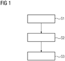
- Figure 1 shows a flowchart of the method according to the invention with the method steps S1 to S3 schematically.
- the individual method steps can each by the computing unit or its subunits are carried out.
- a three-dimensional model of a building can be stored in the computing unit.
- the three-dimensional digital model can be a computer-generated CAD or ifc model in which the parts of the building are semantically annotated, such as 3D body y is a door.
- the three-dimensional model is referred to as an input model 10.
- the computing unit can also be connected to one or more units, such as a display unit.
- the display unit can display any data to the user in three dimensions. The user can therefore perceive the building in three dimensions with the help of VR glasses or AR glasses.
- rules and / or standards 30 can be stored in the computing unit, which must be used for the placement of elements 20 to be placed in the building.
- This can be a distance rule 30 for fire detectors 20, for example.
- the distance rule can be aimed at ensuring that fire detectors are at least 50 cm away from the wall.
- Another rule can be that the detection areas of the fire detectors in the room cover the floor area of the room.
- the rules can differ between different administrative areas (regional, country, federal state, canton, etc.).
- the rules can differ between different types of use of the building (office building, hospital, airport, apartment building, warehouse, etc.). Within the building, the rules can also differ between different room types (office, kitchen, washroom, storage, etc.).
- the computing unit or a storage unit of the computing unit can store the data.
- the computing unit In the case of a representation in virtual space, VR, the computing unit generates a virtual model of the building, through which the user can move virtually. VR has proven to be particularly advantageous for new buildings in the early planning phase.
- the user can select the element 20 to be placed S2, for example a detector, in a menu or by voice command.
- the associated rule 30 is then determined or selected and applied to the input model 10. For example, it emerges from the input model 10 that the building is the use type of an airport.
- a special set of rules 30 for device placement applies to the exemplary airport, which is determined or selected S2.
- the valid and invalid areas 12, 14 for a placement of the element 20 to be placed are then determined S3 using the associated rule.
- These areas 12, 14 can be visually displayed to the user, for example the invalid areas in red and / or the valid areas in green.
- any other type of marking can be used.
- the user can place the element 20 to be placed by determining the location or the place for the placement through his line of sight (crosshair or device symbol) and by carrying out a placement measure (eg clicking on the pointing device or voice command).
- a placement measure eg clicking on the pointing device or voice command.
- the location or location for the placement can be determined by an additional pointing device, the location of which is referenced in the room by the VR system.
- the device can then be displayed in the virtual environment and its position can be saved in the digital building model.
- the completed placement of the placed element 20 can change the valid ranges 12 for the placement of further elements.
- no further elements can be placed directly above the existing element 20.
- the placement of further elements in the coverage area of the element 20 that has already been placed is disadvantageous, particularly with regard to economic aspects. Therefore, the permissible and impermissible ranges 12, 14 can be based on of the updated input model 10 are recalculated and visualized.
- an element 20 to be placed is placed in an impermissible area 14, this placement attempt can be recognized as an error and displayed to the user.
- a conscious placement can include further steps, which can also be documented.
- the computing unit can independently find a new location for the element 20 to be placed, possibly optimized with regard to costs, visibility, cable length, etc. This position is then displayed virtually and only has to be confirmed.
- the above method can also be used.
- AR has proven to be particularly advantageous with regard to the renovation of existing buildings or after the shell construction phase of new buildings.
- the following special features are important here.
- the regional scope of the associated rule 30 can be determined via a position determining unit.
- the position of the user in the input model 10 can be determined using indoor positioning systems, for example markers, WLAN tracking, etc.
- additional obstacles can be taken into account by a scanner unit that are not entered in the input model.
- the obstacles can be plants or furniture, etc.
- the location or location for the placement of the device can be displayed by means of a pointing element which is visible in the real building and can be detected by the camera unit of AR glasses or in the smartphone.
- the pointing element can be, for example, a laser pointer, pointing with the finger or pointing stick.
- the Figures 2 and 3 each show an input model 10 according to an embodiment of the invention.
- the input model 10 has a specific valid area 12 in which the element 20 to be placed can be placed in a permissible manner.
- the valid range is determined by the method according to the invention. In this area, the minimum distance D, 30 is fulfilled as an associated condition.
- Figure 2 shows the element to be placed after step 3, before placement.
- Figure 3 shows the element already placed.
Landscapes
- Engineering & Computer Science (AREA)
- Theoretical Computer Science (AREA)
- Physics & Mathematics (AREA)
- General Engineering & Computer Science (AREA)
- General Physics & Mathematics (AREA)
- Computer Hardware Design (AREA)
- Geometry (AREA)
- Architecture (AREA)
- Human Computer Interaction (AREA)
- Computer Graphics (AREA)
- Software Systems (AREA)
- Evolutionary Computation (AREA)
- Civil Engineering (AREA)
- Computational Mathematics (AREA)
- Mathematical Analysis (AREA)
- Mathematical Optimization (AREA)
- Pure & Applied Mathematics (AREA)
- Structural Engineering (AREA)
- Processing Or Creating Images (AREA)
- User Interface Of Digital Computer (AREA)
Abstract
Description
- Die Erfindung betrifft ein computer-implementiertes Verfahren zum Bestimmen mindestens eines Bereichs in mindestens einem Eingabemodell für mindestens ein zu platzierendes Element. Ferner ist die Erfindung auf eine entsprechende Recheneinheit und Computerprogrammprodukt gerichtet. Die Erfindung kann insbesondere in dem technischen Bereich der Gebäudeausrüstung angesiedelt sein.
- Virtual Reality, oder auch Virtuelle Realität (VR) genannt, gewinnt zunehmend an Bedeutung. Die virtuelle Realität bezeichnet die Darstellung einer virtuellen Welt, welche computergeneriert ist. Die virtuelle Welt kann beispielsweise an die reale Welt angelehnt sein. Ferner steht die virtuelle Realität in engem Zusammenhang mit VR-Brillen. Durch den Einsatz der VR-Brillen ist der Anwender vorteilhafterweise nicht mehr auf den Monitor angewiesen, sondern hat ein 3D-Bild zur Verfügung und kann den Kopf komfortabel in alle Richtungen drehen, um die virtuelle Welt zu verfolgen.
- Durch die VR-Brille kann der Anwender auch einen Gebäudeplan dreidimensional wahrnehmen. In diesen Gebäudeplan müssen oftmals nachträglich Brandmeldevorrichtungen oder andere zu platzierende Elemente platziert werden. Demnach ist oftmals eine Änderung des Gebäudeplans, wie Erweiterung um ein Element, erforderlich.
- Gemäß dem Stand der Technik wird die Installation oder Platzierung eines zu platzierenden Elementes in den Gebäudeplan, wie beispielsweise Brandmelder bzw. Brandmeldevorrichtung, durch einen Fachexperten manuell vorgenommen. Der Fachexperte muss hierbei jedoch auf komplexe und zeitaufwendige Art und Weise sicherstellen, dass bestimmte Regeln, Normen und/oder auch Randbedingungen erfüllt werden. Beispielsweise muss der Brandmelder einen bestimmten Abstand von einer Wand wahren etc., siehe weiter unten. Herkömmlicherweise platziert der Fachexperte in mehreren Durchläufen manuell das zu platzierende Element. Die Regeln, Normen oder Randbedingungen müssen überprüft und erfüllt werden. Anschließend wird der Gebäudeplan von einer zertifizierenden Stelle geprüft und abgenommen.
- Die vorliegende Erfindung stellt sich daher die objektive technische Aufgabe ein Verfahren zum Bestimmen mindestens eines Bereichs in mindestens einem Eingabemodells für mindestens ein zu platzierendes Element bereitzustellen, welches zuverlässiger und effizienter ist.
- Die oben genannte Aufgabe wird erfindungsgemäß durch ein Verfahren zum Bestimmen mindestens eines Bereichs in mindestens einem Eingabemodell für mindestens ein zu platzierendes Element, aufweisend die Schritte:
- a. Empfangen eines Eingabedatensatzes aufweisend das mindestens eine zu platzierende Element, eine Vielzahl von Bedingungen; das mindestens eine Eingabemodell;
- b. Bestimmen mindestens einer zugehörigen Bedingung aus der Vielzahl von Bedingungen; und
- c. Bestimmen mindestens eines gültigen und/oder ungültigen Bereichs des mindestens einen Eingabemodells in Abhängigkeit von der zugehörigen Bedingung; wobei
- d. der mindestens eine gültige Bereich die zugehörige Bedingung zumindest zum Teil erfüllt.
- Dementsprechend ist die Erfindung auf ein Verfahren zum Bestimmen mindestens eines Bereichs eines Eingabemodells für ein zu platzierendes Element gerichtet.
- In einem ersten Schritt wird ein Eingabedatensatz empfangen. Der Eingabedatensatz umfasst zumindest das zu platzierende Element, die Vielzahl der Bedingungen und ein Eingabemodell.
- Das zu platzierende Element ist dasjenige Element, welches mit Hilfe des Verfahrens platziert wird. Beispielhafte Elemente sind Elemente eines Bauwerks, insbesondere eines Gebäudes, wie Brandmelder und Rauchmelder. Weitere andere beispielhafte Elemente sind Sensoren und Aktuatoren. Hierbei kann es sich um ein neues Element oder um ein bereits bestehendes Element handeln. Beispielsweise kann ein neues Element oder sonstiges Element erstmalig platziert werden oder erneut platziert werden.
- Die Bedingungen können auch als Vorgaben bezeichnet werden. Sie müssen bei der Platzierung des zu platzierenden Elementes in einem Bereich des Eingabemodells berücksichtigt werden. Das zu platzierende Element darf lediglich in bestimmte Bereiche des Eingabemodells platziert werden, welche die Bedingungen erfüllen. Mit anderen Worten, kann das platzierende Element nicht an beliebiger Stelle platziert werden. Der Begriff Platzieren kann auch als Einrichten oder Installieren ausgelegt werden. Beispielhafte Bedingungen sind Regeln und Normen, wie Abstandsregeln für Rauchmelder oder Brandmelder, Erreichbarkeitskriterien der Handmelder, Sichtbarkeitskriterien für optische Warneinrichtungen etc. Hinsichtlich der Abstandsregeln müssen beispielsweise die Brandmelder einen bestimmten Abstand von der Wand oder auch Steckdosen einen bestimmten Abstand vom Fußboden haben. Dieser Abstand kann auch als Mindestabstand betrachtet werden. Ferner müssen die Erfassungsbereiche aller Brandmelder in einem Raum die Grundfläche des Raums abdecken usw.
- Das Eingabemodell kann zweidimensional oder dreidimensional ausgestaltet sein. Beispielsweise ist das dreidimensionale digitale Modell ein computergeneriertes CAD- oder ifc-Modell, in welchem das Bauwerk als virtuelles Modell geometrisch visualisiert ist. Vorzugsweise sind in dem obigen Gebäudemodell die Gebäudeteile semantisch annotiert. Das Eingabemodell kann einem Benutzer dargestellt werden, insbesondere durch eine Virtual Reality (VR)- oder Augmented Reality (AR)- Brille. Alternativ können andere Anzeigeeinheiten verwendet werden.
- Bei AR ist eine Überlagerung zum realen Gebäude visualisiert, während bei VR nur die virtuelle Welt dargestellt wird. VR hat sich hinsichtlich der Planung eines Neubaus als vorteilhaft erwiesen, da noch kein reales Gebäude vorhanden ist. AR kann dagegen bei existierenden Gebäude vorteilhafterweise zum Einsatz kommen, wobei die virtuelle Welt der realen Welt visuell überlagert wird.
- In einem zweiten Schritt werden diejenigen ein oder mehreren Bedingungen ausgewählt, welche mit dem zu platzierenden Element in Verbindung stehen oder mit diesem assoziiert werden können. Beispielsweise können sich die Bedingungen hinsichtlich des Platzierungsbereichs unterscheiden, wie nach Region, Land, Bundesland, Kanton etc. Ferner können sich die Bedingungen hinsichtlich des Gebäudetyps unterscheiden, wie Bürogebäude, Krankenhaus, Flughafen, Wohnhaus, Lagerhaus etc. Ferner können sich die Bedingungen hinsichtlich Raum- oder Zimmertyp unterscheiden, wie Bürozimmer, Küche, Waschraum, Lagerraum etc. Die zutreffenden Regeln werden für das zu platzierende Element ausgewählt und in dem nächsten Schritt berücksichtigt.
- In einem dritten Schritt wird der mindestens eine gültige und/oder ungültige Bereich des Eingabemodells in Abhängigkeit von der mindestens einen zugehörigen Bedingung bestimmt. Mit anderen Worten wird die zugehörige Bedingung auf das Eingabemodell angewendet. Die gültigen und ungültigen Bereiche können anhand der zugehörigen Bedingung festgestellt werden. Die Bereiche sind insbesondere Teilbereiche des Eingabemodells bzw. der zugrundeliegenden Einheit. Die zugrundeliegende Einheit kann das obige Gebäude sein. Die gültigen Bereiche können auch als zulässige Bereiche bezeichnet werden, in welche das zu platzierende Element platziert werden soll. Bezugnehmend auf das obige Beispiel eines Brandmelders, bestimmt das erfindungsgemäße Verfahren denjenigen Teilbereich des Gebäudes, in welchem der Brandmelder die Bedingung des Mindestabstands von den Wänden und/oder weitere Bedingungen erfüllt.
- Der Vorteil liegt darin, dass das erfindungsgemäße Verfahren zum Bestimmen mindestens eines Bereichs eines Eingabemodells für ein zu platzierendes Element sowie weitere Schritte der Platzierung selbständig oder eigenständig durch eine Recheneinheit effizient durchgeführt wird. Dadurch kann Fachpersonal mit Expertenknowhow sowie Zeit eingespart werden. Weiterhin ist die Recheneinheit vorteilhafterweise weniger fehleranfällig und somit zuverlässiger. Folglich können die Kosten, die beispielsweise durch mögliche spätere Korrekturen verursacht werden, vermieden oder zumindest erheblich reduziert werden.
- Durch das Verfahren können somit bestehende Gebäudepläne flexibel und dynamisch angepasst werden ohne Expertenwissen oder andere Komponenten zu benötigen. Der Gebäudeplan kann somit jederzeit beliebig auch von Nichtexperten um Elemente erweitert werden, da direktes visuelles Feedback über die Regelkonformität gegeben wird. Dadurch wird die Anpassbarkeit und Reaktionszeit auf Änderungen erheblich verbessert.
- In einer Ausgestaltung weist das Verfahren weiterhin das Anzeigen des mindestens einen gültigen Bereichs und/oder des mindestens einen ungültigen Bereichs auf, insbesondere durch eine Virtual Reality (VR)- oder Augmented Reality (AR)- Brille oder eine sonstige Anzeigeeinheit. Dementsprechend kann dem Benutzer das Eingabemodell dargestellt werden, insbesondere durch eine Virtual Reality (VR)- oder Augmented Reality (AR)- Brille, wie weiter oben geschrieben. Zusätzlich können dem Benutzer auch weitere Daten angezeigt werden. Zusätzlich kann der bestimmte Bereich dem Benutzer farblich angezeigt werden.
- In einer weiteren Ausgestaltung weist das Verfahren weiterhin das Platzieren des mindestens einen zu platzierenden Elementes in den mindestens einen bestimmten Bereich des Eingabemodells auf; wobei das Platzieren das
- Durchführen mindestens einer Platzierungsmaßnahme, falls der mindestens eine Bereich ein gültiger Bereich ist; oder
- Ausgeben eines Platzierungsfehlers, falls der mindestens eine Bereich ein ungültiger Bereich ist; umfasst.
- Dementsprechend kann im Fall einer VR-Brille der Benutzer den Ort oder die Stelle der Platzierung in dem gültigen Bereich durch seine Blickrichtung bestimmen und eine Aktion oder Maßnahme durchführen. Im anderen Fall einer AR-Brille kann der tatsächliche gültige Bereich und/oder der Ort auch durch eine Positionsbestimmungseinheit referenziert werden.
- In einer weiteren Ausgestaltung weist das Verfahren weiterhin das Anzeigen des platzierten Elementes in dem mindestens einen gültigen Bereich nach dem Durchführen der mindestens einen Platzierungsmaßnahme und/oder des Platzierungsfehlers nach Erkennung des Platzierungsfehlers auf. Dementsprechend kann der bestimmte gültige Bereich mit oder ohne dem platzierten Element dem Benutzer ebenfalls visuell angezeigt werden. Vor der Platzierung zeigt die Anzeige folglich noch kein platziertes Element an, sondern erst nach erfolgreicher Platzierung. Andernfalls, nach erfolgloser Platzierung im Fehlerfall, kann der Platzierungsfehler angezeigt oder anderweitig ausgegeben werden.
- In einer weiteren Ausgestaltung ist die mindestens eine Platzierungsmaßnahme ein Nutzerbefehl, insbesondere in Form eines Klicks, einer Handzeicheneingabe, einer Spracheingabe oder einer Texteingabe. Dementsprechend erfolgt die Platzierungsmaßnahme durch den Benutzer in Form eines Befehls. Hierzu sind unterschiedliche Eingabemöglichkeiten oder Befehle möglich. Alternativ kann die Recheneinheit die Platzierung selbst durchführen ohne Nutzerinteraktion, insbesondere eine Anweisung ausführen. Vor der Platzierung durch die Recheneinheit kann der Benutzer den bestimmten Bereich oder die Stelle des zu platzierenden Elements durch die Recheneinheit bestätigen.
- In einer weiteren Ausgestaltung weist das Verfahren weiterhin das Anpassen des mindestens einen Eingabemodells durch Bestimmen und Ergänzen der Position oder Stelle des platzierten Elementes und/oder Anpassen anderer zugehöriger Daten des platzierten Elementes nach dem Durchführen der mindestens einen Platzierungsmaßnahme auf.
- In einer weiteren Ausgestaltung weist das Verfahren weiterhin das Aktualisieren des Eingabemodells anhand der angepassten Daten auf.
- Dementsprechend wird das Eingabemodell nach dem Durchführen des erfindungsgemäßen Verfahrens aktualisiert, um die bestimmten Bereiche zu berücksichtigen. Beispielsweise können keine weiteren zu platzierenden Elemente über dem bereits platzierten Element bzw. an dessen Stelle platziert werden.
- Ferner betrifft die Erfindung eine Recheneinheit zum Durchführen des obigen Verfahrens.
- Die Erfindung betrifft ferner ein Computerprogrammprodukt mit einem Computerprogramm, das Mittel zur Durchführung des oben beschriebenen Verfahrens, wenn das Computerprogramm auf einer programmgesteuerten Einrichtung zur Ausführung gebracht wird. Ein Computerprogrammprodukt, wie z.B. ein Computerprogramm-Mittel, kann beispielsweise als Speichermedium, wie z.B. Speicherkarte, USB-Stick, CD-ROM, DVD, oder auch in Form einer herunterladbaren Datei von einem Server in einem Netzwerk bereitgestellt oder geliefert werden. Dies kann zum Beispiel in einem drahtlosen Kommunikationsnetzwerk durch die Übertragung einer entsprechenden Datei mit dem Computerprogrammprodukt oder dem Computerprogramm-Mittel erfolgen. Als programmgesteuerte Einrichtung kommt insbesondere eine Steuereinrichtung, wie beispielsweise eine Industriesteuerungs-PC oder eine Speicherprogrammierbare Steuerung oder ein Programmable Logic Controller, kurz PLC, oder ein Mikroprozessor für eine Smartcard oder dergleichen in Frage.
- In der folgenden detaillierten Beschreibung werden vorliegend bevorzugte Ausführungsformen der Erfindung weiter beschrieben mit Bezug auf die folgenden Figuren.
- FIG 1
- zeigt ein erfindungsgemäßes Ablaufdiagramm.
- FIG 2
- zeigt ein Eingabemodell mit dem zu platzierenden Element vor der Platzierung gemäß einer Ausführungsform der Erfindung.
- FIG 3
- zeigt ein Eingabemodell mit dem platzierten Element nach der Platzierung gemäß einer Ausführungsform der Erfindung.
- Im Folgenden werden bevorzugte Ausführungsformen der vorliegenden Erfindung in Bezug auf die Figuren beschrieben.
-
Figur 1 stellt ein Ablaufdiagramm des erfindungsgemäßen Verfahrens mit den Verfahrensschritten S1 bis S3 schematisch dar. Die einzelnen Verfahrensschritte können jeweils durch die Recheneinheit oder auch deren Untereinheiten durchgeführt werden. - In der Recheneinheit kann ein dreidimensionales Modell eines Gebäudes gespeichert werden. Das dreidimensionale digitale Modell kann ein computergeneriertes CAD- oder ifc-Modell sein, in dem die Gebäudeteile semantisch annotiert sind, wie beispielsweise 3D Körper y ist eine Türe. Das dreidimensionale Modell wird als Eingabemodell 10 bezeichnet.
- Die Recheneinheit kann ferner mit einer oder mehreren Einheiten verbunden sein, wie Anzeigeeinheit. Die Anzeigeneinheit kann dem Benutzer jegliche Daten dreidimensional darstellen. Der Benutzer kann demnach mit Hilfe einer VR-Brille oder AR-Brille das Gebäude dreidimensional wahrnehmen.
- Weiterhin können in der Recheneinheit Regeln und/oder Normen 30 hinterlegt werden, die für die Platzierung zu platzierender Elemente 20 im Gebäude verwendet werden müssen. Dies kann zum Beispiel eine Abstandsregel 30 für Brandmelder 20 sein. Die Abstandsregel kann darauf gerichtet sein, dass Brandmelder von der Wand einen Abstand von mindestens 50 cm haben. Eine weitere Regel kann darauf gerichtet sein, dass die Erfassungsbereiche der Brandmelder im Raum die Grundfläche des Raums abdecken. Die Regeln können sich zwischen verschiedenen Verwaltungsbereichen unterscheiden (regional, Land, Bundesland, Kanton etc.). Ferner können sich die Regeln zwischen verschiedenen Nutzungstypen der Gebäude unterscheiden (Bürogebäude, Krankenhaus, Flughafen, Wohnhaus, Lagerhaus etc.). Innerhalb des Gebäudes können sich die Regeln auch zwischen verschiedenen Raumtypen unterscheiden (Büro, Küche, Waschraum, Lager etc.).
- Zusätzlich kann die Recheneinheit oder eine Speichereinheit der Recheneinheit die Daten speichern.
- Im Fall einer Darstellung im virtuellen Raum, VR, wird durch die Recheneinheit ein virtuelles Modell des Gebäudes erzeugt, durch das sich der Benutzer virtuell bewegen kann. VR hat sich hinsichtlich Neubauten in der frühen Planungsphase als besonders vorteilhaft erwiesen. Der Benutzer kann in einem Menü oder durch Sprachbefehl das zu platzierende Element 20 auswählen S2, beispielsweise einen Detektor. Daraufhin wird die zugehörige Regel 30 bestimmt oder ausgewählt sowie auf das Eingabemodell 10 angewendet. Beispielsweise ergibt sich aus dem Eingabemodell 10, dass es sich bei dem Gebäude um den Nutzungstyp eines Flughafens handelt. Für den beispielhaften Flughaften gilt ein spezieller Regelsatz 30 zur Geräteplatzierung, welcher bestimmt bzw. ausgewählt wird S2. Daraufhin werden anhand der zugehörigen Regel die gültigen und ungültigen Bereiche 12, 14 für eine Platzierung des zu platzierenden Elements 20 bestimmt S3. Diese Bereiche 12, 14 können dem Benutzer optisch dargestellt werden, beispielsweise die ungültigen Bereiche in rot und/oder die gültigen Bereiche in grün. Alternativ oder zusätzlich zur Farbe können jegliche andere Markierungsarten verwendet werden. Der Benutzer kann das zu platzierende Element 20 platzieren indem er den Ort oder die Stelle für die Platzierung durch seine Blickrichtung bestimmt (Fadenkreuz oder Gerätesymbol) und eine Platzierungsmaßnahme durchführt (z.B. Klicken auf Zeigegerät oder Sprachbefehl). Alternativ oder zusätzlich kann der Ort oder die Stelle für die Platzierung durch ein zusätzliches Zeigegerät bestimmt werden, dessen Lage im Raum mit der VR-System referenziert wird. Daraufhin kann das Gerät in der virtuellen Umgebung angezeigt und seine Position im digitalen Gebäudemodell gespeichert werden.
- Die abgeschlossene Platzierung des platzierten Elements 20 kann die gültigen Bereiche 12 für die Platzierung weiterer Elemente ändern. Insbesondere können keine weiteren Elemente direkt über dem vorhandenen platzierten Element 20 platziert werden. Die Platzierung weiterer Elemente im Abdeckungsbereich des bereits platzierten Elements 20 ist insbesondere hinsichtlich ökonomischer Gesichtspunkte von Nachteil. Daher können die zulässigen und unzulässigen Bereiche 12, 14 anhand des aktualisierten Eingabemodells 10 neu berechnet und visualisiert werden.
- Falls ein zu platzierendes Element 20 in einem unzulässigen Bereich 14 platziert wird, kann dieser Platzierungsversuch als Fehler erkannt und dem Benutzer angezeigt werden. Eine bewusste Platzierung kann weitere Schritte vorsehen, welche auch dokumentiert werden können. Alternativ oder zusätzlich kann die Recheneinheit selbstständig einen neuen Ort für das zu platzierende Element 20 finden, gegebenenfalls optimiert hinsichtlich Kosten, Sichtbarkeit, Kabellänge etc. Diese Position wird dann virtuell angezeigt und muss lediglich bestätigt werden.
- Im Fall der Darstellung in Mixed oder Augmented Reality Umgebungen ist ebenfalls das obige Verfahren anwendbar. AR hat sich hinsichtlich der Renovierung von Bestandsgebäuden oder nach der Rohbauphase von Neubauten als besonders vorteilhaft erwiesen.
Hierbei sind die folgenden Besonderheiten von Bedeutung. Nachdem der Benutzer sich in diesem Fall tatsächlich vor Ort in dem Gebäude befindet in dem das zu platzierende Element platziert werden soll, kann der regionale Gültigkeitsbereich der zugehörigen Regel 30 über eine Positionsbestimmungseinheit ermittelt werden. Ferner kann die Position des Benutzers im Eingabemodell 10 anhand von Indoor-Positioningsystemen festgestellt werden, beispielsweise Marker, WLAN-Tracking etc. Ferner können zusätzliche Hindernisse durch eine Scanner-Einheit berücksichtigt werden, die im Eingabemodell nicht eingetragen sind. Bei den Hindernissen kann es sich beispielsweise um Pflanzen oder Mobiliar etc. handeln. Das Anzeigen der Stelle oder des Orts für die Platzierung des Geräts kann durch ein im echten Gebäude sichtbares, durch die Kameraeinheit einer AR-Brille oder im Smartphone erfassbares Zeigeelement erfolgen. Bei dem Zeigeelement kann es sich beispielsweise um einen Laser-Pointer, Zeigen mit dem Finger oder Zeigestab handeln. - Die
Figuren 2 und 3 zeigen jeweils ein Eingabemodell 10 gemäß einer Ausführungsform der Erfindung. Das Eingabemodell 10 weist einen bestimmten gültigen Bereich 12 auf, in welches das zu platzierende Element 20 zulässig platziert werden kann. Der gültige Bereich wird durch das erfindungsgemäße Verfahren bestimmt. In diesem Bereich wird der Mindestabstand D, 30 als zugehörige Bedingung erfüllt. -
Figur 2 zeigt das zu platzierende Elemente nach Verfahrensschritt 3, vor der Platzierung.Figur 3 hingegen zeigt das bereits platzierte Element.
Claims (9)
- Verfahren zum Bestimmen mindestens eines Bereichs (12, 14) in mindestens einem Eingabemodell (10) für mindestens ein zu platzierendes Element (20), aufweisend die Schritte:a. Empfangen eines Eingabedatensatzes aufweisend das mindestens eine zu platzierende Element (20), eine Vielzahl von Bedingungen (30); das mindestens eine Eingabemodell (10) (S1);b. Bestimmen mindestens einer zugehörigen Bedingung (30) aus der Vielzahl von Bedingungen (S2); undc. Bestimmen mindestens eines gültigen (12) und/oder ungültigen Bereichs (14) des mindestens einen Eingabemodells (10) in Abhängigkeit von der zugehörigen Bedingung (30) (S3); wobeid. der mindestens eine gültige Bereich (12) die zugehörige Bedingung (30) zumindest zum Teil erfüllt.
- Verfahren nach Anspruch 1, weiterhin aufweisend Anzeigen des mindestens einen gültigen Bereichs (12) und/oder des mindestens einen ungültigen Bereichs (14), insbesondere durch eine Virtual Reality (VR)- oder Augmented Reality (AR)- Brille oder eine sonstige Anzeigeeinheit.
- Verfahren nach Anspruch 1 oder Anspruch 2, weiterhin aufweisend Platzieren des mindestens einen zu platzierenden Elementes in den mindestens einen bestimmten Bereich des Eingabemodells; wobei das Platzieren das- Durchführen mindestens einer Platzierungsmaßnahme, falls der mindestens eine bestimmte Bereich ein gültiger Bereich (12) ist; oder- Ausgeben eines Platzierungsfehlers, falls der mindestens eine bestimmte Bereich ein ungültiger Bereich (14) ist;umfasst.
- Verfahren nach Anspruch 3, weiterhin aufweisend Anzeigen des platzierten Elementes (20) in dem mindestens einen gültigen Bereich (12) nach dem Durchführen der mindestens einen Platzierungsmaßnahme und/oder des Platzierungsfehlers nach Erkennung des Platzierungsfehlers.
- Verfahren nach Anspruch 3 oder Anspruch 4, wobei die mindestens eine Platzierungsmaßnahme ein Nutzerbefehl ist, insbesondere in Form eines Klicks, einer Handzeicheneingabe, einer Spracheingabe oder einer Texteingabe.
- Verfahren nach einem der Ansprüche 3 bis 5, weiterhin aufweisend Anpassen des mindestens einen Eingabemodells (10) durch Bestimmen und Ergänzen der Position oder Stelle des platzierten Elementes (20) und/oder Anpassen anderer zugehöriger Daten des platzierten Elementes (20) nach dem Durchführen der mindestens einen Platzierungsmaßnahme.
- Verfahren nach Anspruch 6, weiterhin aufweisend Aktualisieren des mindestens einen Eingabemodells (10) anhand der angepassten Daten.
- Recheneinheit zum Durchführen des Verfahrens nach einem der vorhergehenden Ansprüche.
- Computerprogrammprodukt mit einem Computerprogramm, das Mittel zur Durchführung des Verfahrens nach einem der Ansprüche 1 bis 7 aufweist, wenn das Computerprogramm auf einer programmgesteuerten Einrichtung zur Ausführung gebracht wird.
Priority Applications (2)
| Application Number | Priority Date | Filing Date | Title |
|---|---|---|---|
| EP18200985.2A EP3640767B1 (de) | 2018-10-17 | 2018-10-17 | Verfahren zum bestimmen mindestens eines bereichs in mindestens einem eingabemodell für mindestens ein zu platzierendes element |
| US16/653,362 US11748964B2 (en) | 2018-10-17 | 2019-10-15 | Method for determining at least one region in at least one input model for at least one element to be placed |
Applications Claiming Priority (1)
| Application Number | Priority Date | Filing Date | Title |
|---|---|---|---|
| EP18200985.2A EP3640767B1 (de) | 2018-10-17 | 2018-10-17 | Verfahren zum bestimmen mindestens eines bereichs in mindestens einem eingabemodell für mindestens ein zu platzierendes element |
Publications (2)
| Publication Number | Publication Date |
|---|---|
| EP3640767A1 true EP3640767A1 (de) | 2020-04-22 |
| EP3640767B1 EP3640767B1 (de) | 2024-09-11 |
Family
ID=64100553
Family Applications (1)
| Application Number | Title | Priority Date | Filing Date |
|---|---|---|---|
| EP18200985.2A Active EP3640767B1 (de) | 2018-10-17 | 2018-10-17 | Verfahren zum bestimmen mindestens eines bereichs in mindestens einem eingabemodell für mindestens ein zu platzierendes element |
Country Status (2)
| Country | Link |
|---|---|
| US (1) | US11748964B2 (de) |
| EP (1) | EP3640767B1 (de) |
Cited By (1)
| Publication number | Priority date | Publication date | Assignee | Title |
|---|---|---|---|---|
| EP4191461A1 (de) * | 2021-12-02 | 2023-06-07 | Siemens Schweiz AG | Computer-implementiertes verfahren zur platzierung von elementen in einem raum eines gebäudes |
Families Citing this family (2)
| Publication number | Priority date | Publication date | Assignee | Title |
|---|---|---|---|---|
| US20240221049A1 (en) * | 2021-03-11 | 2024-07-04 | Seoul National University R&DB Foudation | Method and system for creating indoor image datasets using procedural generation and 3D mesh conversion |
| CN115145428B (zh) | 2021-03-29 | 2025-10-31 | 北京小米移动软件有限公司 | 一种指向方法、装置、电子设备及存储介质 |
Citations (3)
| Publication number | Priority date | Publication date | Assignee | Title |
|---|---|---|---|---|
| US5444836A (en) * | 1994-03-10 | 1995-08-22 | Information And Graphics Systems, Inc. | Apparatus and method for improved placement of objects in computer aided drafting |
| US20160171143A1 (en) * | 2014-12-11 | 2016-06-16 | Mentor Graphics Corporation | Circuit design layout in multiple synchronous representations |
| US20180096528A1 (en) * | 2016-09-30 | 2018-04-05 | Intel Corporation | Automatic placement of augmented reality models |
Family Cites Families (169)
| Publication number | Priority date | Publication date | Assignee | Title |
|---|---|---|---|---|
| US5101436A (en) * | 1990-05-11 | 1992-03-31 | Optigraphics Corporation | Hybrid image editor |
| US6016147A (en) * | 1995-05-08 | 2000-01-18 | Autodesk, Inc. | Method and system for interactively determining and displaying geometric relationships between three dimensional objects based on predetermined geometric constraints and position of an input device |
| US6377263B1 (en) * | 1997-07-07 | 2002-04-23 | Aesthetic Solutions | Intelligent software components for virtual worlds |
| US20070008099A1 (en) * | 1999-09-01 | 2007-01-11 | Nettalon Security Systems, Inc. | Method and apparatus for remotely monitoring a site |
| US6972676B1 (en) * | 1999-09-01 | 2005-12-06 | Nettalon Security Systems, Inc. | Method and apparatus for remotely monitoring a site |
| US7062722B1 (en) * | 2000-08-22 | 2006-06-13 | Bruce Carlin | Network-linked interactive three-dimensional composition and display of saleable objects in situ in viewer-selected scenes for purposes of promotion and procurement |
| US7043695B2 (en) * | 2000-09-19 | 2006-05-09 | Technion Research & Development Foundation Ltd. | Object positioning and display in virtual environments |
| US6690960B2 (en) * | 2000-12-21 | 2004-02-10 | David T. Chen | Video-based surgical targeting system |
| US7467074B2 (en) * | 2002-02-01 | 2008-12-16 | Ford Motor Company | System and method of interactively assembling a model |
| US8369607B2 (en) * | 2002-03-27 | 2013-02-05 | Sanyo Electric Co., Ltd. | Method and apparatus for processing three-dimensional images |
| JP3944019B2 (ja) * | 2002-07-31 | 2007-07-11 | キヤノン株式会社 | 情報処理装置および方法 |
| US20050071135A1 (en) * | 2003-09-30 | 2005-03-31 | Vredenburgh David W. | Knowledge management system for computer-aided design modeling |
| US7277572B2 (en) * | 2003-10-10 | 2007-10-02 | Macpearl Design Llc | Three-dimensional interior design system |
| US7479959B2 (en) * | 2004-02-23 | 2009-01-20 | Ironclad Llc | Geometric modeling system with intelligent configuring of solid shapes |
| US7425958B2 (en) * | 2004-10-25 | 2008-09-16 | Adobe Systems Incorporated | Perspective editing tools for 2-D images |
| WO2007084826A2 (en) * | 2006-01-11 | 2007-07-26 | The Gannon Technologies Group | Program managed design for complex construction projects |
| JP4148276B2 (ja) * | 2006-05-09 | 2008-09-10 | ソニー株式会社 | 位置推定装置、位置推定方法及びプログラム記録媒体 |
| WO2009040675A2 (en) * | 2007-09-24 | 2009-04-02 | View22 Technology Inc. | Facilitating electronic commerce via a 3d virtual environment |
| DE102007045835B4 (de) * | 2007-09-25 | 2012-12-20 | Metaio Gmbh | Verfahren und Vorrichtung zum Darstellen eines virtuellen Objekts in einer realen Umgebung |
| US9092053B2 (en) * | 2008-06-17 | 2015-07-28 | Apple Inc. | Systems and methods for adjusting a display based on the user's position |
| US9213785B2 (en) * | 2009-02-03 | 2015-12-15 | Thomas Plewe | Systems and methods for component-based architecture design |
| US8970690B2 (en) * | 2009-02-13 | 2015-03-03 | Metaio Gmbh | Methods and systems for determining the pose of a camera with respect to at least one object of a real environment |
| CN102317945A (zh) * | 2009-02-20 | 2012-01-11 | 太阳能公司 | 自动化太阳能收集器安装设计 |
| AU2010216286A1 (en) * | 2009-02-20 | 2011-07-21 | Sunpower Corporation | Automated solar collector installation design including ability to define heterogeneous design preferences |
| JP5585794B2 (ja) * | 2009-02-20 | 2014-09-10 | サンパワー コーポレイション | ソーラーコレクタ設置設計を生成する方法、プログラムおよび装置 |
| US8255205B2 (en) * | 2009-05-29 | 2012-08-28 | Hyperquest, Inc. | Automation of auditing claims |
| CA2807614C (en) * | 2009-08-18 | 2018-10-30 | Airway Limited | Endoscope simulator |
| US20110213480A1 (en) * | 2010-03-01 | 2011-09-01 | Genexis Design Inc. | Parametric product configuration system |
| CN102884532B (zh) * | 2010-03-09 | 2022-06-10 | 欧特克公司 | 用于以建筑信息建模进行施工现场管理和操作的系统和方法 |
| US8842893B2 (en) * | 2010-04-30 | 2014-09-23 | Medtronic Navigation, Inc. | Method and apparatus for image-based navigation |
| KR101708306B1 (ko) * | 2010-09-13 | 2017-02-20 | 엘지전자 주식회사 | 이동 단말기 및 그의 3d 이미지 합성방법 |
| US8860760B2 (en) * | 2010-09-25 | 2014-10-14 | Teledyne Scientific & Imaging, Llc | Augmented reality (AR) system and method for tracking parts and visually cueing a user to identify and locate parts in a scene |
| US20130072784A1 (en) * | 2010-11-10 | 2013-03-21 | Gnanasekar Velusamy | Systems and methods for planning image-guided interventional procedures |
| US20120120113A1 (en) * | 2010-11-15 | 2012-05-17 | Eduardo Hueso | Method and apparatus for visualizing 2D product images integrated in a real-world environment |
| US9129438B2 (en) * | 2011-01-18 | 2015-09-08 | NedSense Loft B.V. | 3D modeling and rendering from 2D images |
| US20120296611A1 (en) * | 2011-05-20 | 2012-11-22 | Google Inc. | System and Methods for Structure Design, Analysis, and Implementation |
| CN103702726B (zh) * | 2011-05-23 | 2016-01-13 | 乐高公司 | 玩具搭建系统、产生构建指令的方法和数据处理系统 |
| US9443353B2 (en) * | 2011-12-01 | 2016-09-13 | Qualcomm Incorporated | Methods and systems for capturing and moving 3D models and true-scale metadata of real world objects |
| JP5970872B2 (ja) * | 2012-03-07 | 2016-08-17 | セイコーエプソン株式会社 | 頭部装着型表示装置および頭部装着型表示装置の制御方法 |
| CN104488002A (zh) * | 2012-03-20 | 2015-04-01 | 西门子公司 | 行李可视化和虚拟开检 |
| US10216355B2 (en) * | 2012-06-17 | 2019-02-26 | Atheer, Inc. | Method for providing scale to align 3D objects in 2D environment |
| US9696547B2 (en) * | 2012-06-25 | 2017-07-04 | Microsoft Technology Licensing, Llc | Mixed reality system learned input and functions |
| US10084611B2 (en) * | 2012-06-29 | 2018-09-25 | Siemens Schweiz Ag | Programmable symbol animation pre-processor for building automation graphics |
| HK1205326A1 (en) * | 2012-07-27 | 2015-12-11 | 日本电气方案创新株式会社 | Three-dimensional environment sharing system, and three-dimensional environment sharing method |
| US9292629B2 (en) * | 2012-07-27 | 2016-03-22 | Autodesk, Inc. | Building path identification |
| US20140074272A1 (en) * | 2012-09-13 | 2014-03-13 | Parametric Products Intellectual Holdings, Llc | System for creation of three dimensional printing files |
| US9552673B2 (en) * | 2012-10-17 | 2017-01-24 | Microsoft Technology Licensing, Llc | Grasping virtual objects in augmented reality |
| US9368045B2 (en) * | 2012-11-09 | 2016-06-14 | Illinois Tool Works Inc. | System and device for welding training |
| US9201987B2 (en) * | 2012-11-26 | 2015-12-01 | Sunrun, Inc. | Method and system for generating multiple configurations for a solar power system |
| US9129435B2 (en) * | 2012-12-04 | 2015-09-08 | Fuji Xerox Co., Ltd. | Method for creating 3-D models by stitching multiple partial 3-D models |
| US20140240349A1 (en) * | 2013-02-22 | 2014-08-28 | Nokia Corporation | Method and apparatus for presenting task-related objects in an augmented reality display |
| JP6138566B2 (ja) * | 2013-04-24 | 2017-05-31 | 川崎重工業株式会社 | 部品取付作業支援システムおよび部品取付方法 |
| US8884772B1 (en) * | 2013-04-30 | 2014-11-11 | Globestar, Inc. | Building evacuation system with positive acknowledgment |
| AU2013273722A1 (en) * | 2013-12-19 | 2015-07-09 | Canon Kabushiki Kaisha | Method, system and apparatus for removing a marker projected in a scene |
| US10758198B2 (en) * | 2014-02-25 | 2020-09-01 | DePuy Synthes Products, Inc. | Systems and methods for intra-operative image analysis |
| EP2916189B1 (de) * | 2014-03-06 | 2019-05-08 | Hexagon Technology Center GmbH | Qualitätsgesicherte Herstellung |
| US20170329402A1 (en) * | 2014-03-17 | 2017-11-16 | Spatial Intelligence Llc | Stereoscopic display |
| US9398413B1 (en) * | 2014-03-18 | 2016-07-19 | Amazon Technologies, Inc. | Mapping electronic devices within an area |
| US20150310136A1 (en) * | 2014-04-24 | 2015-10-29 | WD Partners, Inc. | Architectural design dashboard |
| US9971853B2 (en) * | 2014-05-13 | 2018-05-15 | Atheer, Inc. | Method for replacing 3D objects in 2D environment |
| US20220383600A1 (en) * | 2014-05-13 | 2022-12-01 | West Texas Technology Partners, Llc | Method for interactive catalog for 3d objects within the 2d environment |
| US11410394B2 (en) * | 2020-11-04 | 2022-08-09 | West Texas Technology Partners, Inc. | Method for interactive catalog for 3D objects within the 2D environment |
| JP2015228050A (ja) * | 2014-05-30 | 2015-12-17 | ソニー株式会社 | 情報処理装置および情報処理方法 |
| JP6348021B2 (ja) * | 2014-09-01 | 2018-06-27 | 株式会社ミツトヨ | 測定器のパラメータ設定方法及び測定器のパラメータ設定プログラム |
| US10070120B2 (en) * | 2014-09-17 | 2018-09-04 | Qualcomm Incorporated | Optical see-through display calibration |
| US20160085884A1 (en) * | 2014-09-23 | 2016-03-24 | Crestron Electronics, Inc. | System and method for modeling a lighting control system |
| EP3221809A1 (de) * | 2014-11-18 | 2017-09-27 | Koninklijke Philips N.V. | Benutzerführungssystem und verfahren, verwendung einer erweiterten realitätsvorrichtung |
| CN105744254B (zh) * | 2014-12-30 | 2017-12-29 | 钰立微电子股份有限公司 | 校正导引系统和校正导引系统的操作方法 |
| US10679396B2 (en) * | 2017-07-13 | 2020-06-09 | Visyn Inc. | Holographic multi avatar training system interface and sonification associative training |
| WO2016116877A1 (en) * | 2015-01-20 | 2016-07-28 | Illinois Tool Works, Inc. | Method, computer program product and apparatus for providing a building options configuration |
| US10410419B2 (en) * | 2015-03-02 | 2019-09-10 | Virtek Vision International Ulc | Laser projection system with video overlay |
| CN107646118B (zh) * | 2015-03-24 | 2022-04-15 | 开利公司 | 用于确定与楼层平面图相关的rf传感器性能的系统和方法 |
| US10944837B2 (en) * | 2015-03-24 | 2021-03-09 | Carrier Corporation | Floor-plan based learning and registration of distributed devices |
| CN107660299B (zh) * | 2015-03-24 | 2021-02-26 | 开利公司 | 建筑物系统的基于楼层平面图的规划 |
| US10459593B2 (en) * | 2015-03-24 | 2019-10-29 | Carrier Corporation | Systems and methods for providing a graphical user interface indicating intruder threat levels for a building |
| US9972133B2 (en) * | 2015-04-24 | 2018-05-15 | Jpw Industries Inc. | Wearable display for use with tool |
| US20170017301A1 (en) * | 2015-07-16 | 2017-01-19 | Hand Held Products, Inc. | Adjusting dimensioning results using augmented reality |
| US10019129B2 (en) * | 2015-08-14 | 2018-07-10 | Siemens Schweiz Ag | Identifying related items associated with devices in a building automation system based on a coverage area |
| WO2017035225A1 (en) * | 2015-08-24 | 2017-03-02 | Aditazz, Inc. | A computer-implemented system and method for placing objects in a room |
| US9922541B2 (en) * | 2015-11-16 | 2018-03-20 | Google Llc | Systems and methods for detecting anomalies in a hazard detection system |
| US20170200286A1 (en) * | 2016-01-12 | 2017-07-13 | Shutterfly, Inc. | System and method for creating and placing a collection of personalized products on a surface |
| DE102016201883A1 (de) * | 2016-02-09 | 2017-08-10 | Siemens Schweiz Ag | Verfahren und Anordnung zur Inbetriebnahme eines Gebäudeautomatisierungssystems |
| US20170256096A1 (en) * | 2016-03-07 | 2017-09-07 | Google Inc. | Intelligent object sizing and placement in a augmented / virtual reality environment |
| US11138306B2 (en) * | 2016-03-14 | 2021-10-05 | Amazon Technologies, Inc. | Physics-based CAPTCHA |
| US10395435B2 (en) * | 2016-04-04 | 2019-08-27 | Occipital, Inc. | System for multimedia spatial annotation, visualization, and recommendation |
| US10824795B2 (en) * | 2016-06-21 | 2020-11-03 | Fernando J. Pinho | Indoor positioning and recording system |
| JP6742850B2 (ja) * | 2016-07-29 | 2020-08-19 | キヤノン株式会社 | レイアウト編集装置、レイアウト編集方法、およびプログラム |
| ES2992065T3 (es) * | 2016-08-16 | 2024-12-09 | Insight Medical Systems Inc | Sistemas de aumento sensorial en procedimientos médicos |
| WO2018063528A1 (en) * | 2016-08-16 | 2018-04-05 | Insight Medical Systems, Inc. | Systems for sensory augmentation in medical procedures |
| EP3336805A1 (de) * | 2016-12-15 | 2018-06-20 | Thomson Licensing | Verfahren und vorrichtung zur platzierung eines virtuellen objekts einer anwendung für erweiterte oder gemischte realität in einer realen 3d-umgebung |
| EP3340187A1 (de) * | 2016-12-26 | 2018-06-27 | Thomson Licensing | Vorrichtung und verfahren zur erzeugung dynamischer virtueller inhalte in gemischter realität |
| US20200265745A1 (en) * | 2017-01-24 | 2020-08-20 | Tienovix, Llc | System and method for adaptive augmented reality guidance for use of equipment systems |
| US20200265754A1 (en) * | 2017-01-24 | 2020-08-20 | Tienovix, Llc | System and method for augmented reality guidance for use of medical equipment systems with transmission of data to remote location |
| US20210295048A1 (en) * | 2017-01-24 | 2021-09-23 | Tienovix, Llc | System and method for augmented reality guidance for use of equipment systems |
| US11782570B2 (en) * | 2017-02-23 | 2023-10-10 | Jue-Hsuan Hsiao | Integration platform of internet of things and virtual device |
| US10102657B2 (en) * | 2017-03-09 | 2018-10-16 | Houzz, Inc. | Generating enhanced images using dimensional data |
| US20180268087A1 (en) * | 2017-03-14 | 2018-09-20 | Patrick Tierney | System and method for evaluating a building project design |
| US10692287B2 (en) * | 2017-04-17 | 2020-06-23 | Microsoft Technology Licensing, Llc | Multi-step placement of virtual objects |
| EP3398551B1 (de) * | 2017-05-03 | 2024-10-30 | Stryker European Operations Holdings LLC | Verfahren zur positionsschätzung von dreidimensionalen knochenmodellen bei der chirurgischen planung eines kompletten fussgelenkersatzes |
| WO2018207662A1 (ja) * | 2017-05-11 | 2018-11-15 | ソニー株式会社 | 情報処理装置、情報処理方法、及びプログラム |
| US10319150B1 (en) * | 2017-05-15 | 2019-06-11 | A9.Com, Inc. | Object preview in a mixed reality environment |
| CA3005051A1 (en) * | 2017-05-16 | 2018-11-16 | Michael J. Schuster | Augmented reality task identification and assistance in construction, remodeling, and manufacturing |
| US20180357670A1 (en) * | 2017-06-07 | 2018-12-13 | International Business Machines Corporation | Dynamically capturing, transmitting and displaying images based on real-time visual identification of object |
| JP6946087B2 (ja) * | 2017-07-14 | 2021-10-06 | キヤノン株式会社 | 情報処理装置及びその制御方法、並びに、プログラム |
| CN107450747B (zh) * | 2017-07-25 | 2018-09-18 | 腾讯科技(深圳)有限公司 | 虚拟角色的位移控制方法和装置 |
| US20190087078A1 (en) * | 2017-09-18 | 2019-03-21 | Tyco Fire & Security Gmbh | Method and Apparatus for Mapping Devices by Using Posted Maps |
| US20190088030A1 (en) * | 2017-09-20 | 2019-03-21 | Microsoft Technology Licensing, Llc | Rendering virtual objects based on location data and image data |
| US10803666B1 (en) * | 2017-09-28 | 2020-10-13 | Apple Inc. | Method and device for synchronizing augmented reality coordinate systems |
| US20190122292A1 (en) * | 2017-10-19 | 2019-04-25 | Walmart Apollo, Llc | System and method for a holographic display for low inventory |
| KR102609767B1 (ko) * | 2017-11-08 | 2023-12-05 | 엘지전자 주식회사 | 디지털 사이니지를 제어하기 위한 방법, 장치 및 기록 매체 |
| US10503843B2 (en) * | 2017-12-19 | 2019-12-10 | Eagle View Technologies, Inc. | Supervised automatic roof modeling |
| WO2019125613A1 (en) * | 2017-12-21 | 2019-06-27 | Walmart Apollo, Llc | System for dynamic pallet-build |
| US11270034B1 (en) * | 2018-01-05 | 2022-03-08 | Shiyuan Shen | Method and system for kitchen cabinet layout |
| JP7146402B2 (ja) * | 2018-01-18 | 2022-10-04 | キヤノン株式会社 | 情報処理装置、および情報処理方法 |
| DK201870347A1 (en) * | 2018-01-24 | 2019-10-08 | Apple Inc. | Devices, Methods, and Graphical User Interfaces for System-Wide Behavior for 3D Models |
| US11651675B2 (en) * | 2018-02-02 | 2023-05-16 | Siemens Schweiz Ag | Safety device inspection |
| JP7021361B2 (ja) * | 2018-02-06 | 2022-02-16 | ウォルマート アポロ,エルエルシー | カスタマイズされた拡張現実品目フィルタリングシステム |
| US20190251750A1 (en) * | 2018-02-09 | 2019-08-15 | Tsunami VR, Inc. | Systems and methods for using a virtual reality device to emulate user experience of an augmented reality device |
| AU2019225931A1 (en) * | 2018-02-22 | 2020-08-20 | Magic Leap, Inc. | Object creation with physical manipulation |
| US10650609B2 (en) * | 2018-02-23 | 2020-05-12 | Sap Se | Virtual prototyping and assembly validation |
| US11819369B2 (en) * | 2018-03-15 | 2023-11-21 | Zoll Medical Corporation | Augmented reality device for providing feedback to an acute care provider |
| US11227439B2 (en) * | 2018-03-29 | 2022-01-18 | Eon Reality, Inc. | Systems and methods for multi-user virtual reality remote training |
| US10467817B1 (en) * | 2018-04-23 | 2019-11-05 | Houzz, Inc. | User device augmented reality virtual item modeling |
| US10916065B2 (en) * | 2018-05-04 | 2021-02-09 | Facebook Technologies, Llc | Prevention of user interface occlusion in a virtual reality environment |
| US11094221B2 (en) * | 2018-06-21 | 2021-08-17 | University Of Utah Research Foundation | Visual guidance system and method for posing a physical object in three dimensional space |
| AU2019302528A1 (en) * | 2018-07-09 | 2021-03-04 | Xr Health Il Ltd | Systems and methods for guiding and measuring neck and shoulder protraction and retraction motions in virtual/augmented reality |
| US11468206B2 (en) * | 2018-08-20 | 2022-10-11 | Sri International | Machine learning system for building renderings and building information modeling data |
| US11029671B1 (en) * | 2018-08-22 | 2021-06-08 | Automated Wiring Systems, LLC | Integrated wire harness batch production using augmented reality |
| ES2966046T3 (es) * | 2018-08-28 | 2024-04-18 | Carrier Corp | Herramienta de diseño integrada para sistemas de seguridad contra incendios |
| US10475250B1 (en) * | 2018-08-30 | 2019-11-12 | Houzz, Inc. | Virtual item simulation using detected surfaces |
| US11004270B2 (en) * | 2018-09-11 | 2021-05-11 | Houzz, Inc. | Virtual item placement system |
| KR102815456B1 (ko) * | 2018-09-12 | 2025-05-30 | 삼성전자주식회사 | 영상 처리를 위한 학습 데이터 생성 방법, 영상 처리 방법, 및 그 장치들 |
| CN110895862B (zh) * | 2018-09-13 | 2023-07-04 | 开利公司 | 火灾探测系统-用于火灾探测设计框架的端对端解决方案 |
| CN110895633B (zh) * | 2018-09-13 | 2026-03-24 | 开利公司 | 火灾探测系统-基于楼层平面图的火灾威胁建模 |
| CN110895864B (zh) * | 2018-09-13 | 2024-02-09 | 开利公司 | 用于火灾设备的与约束一致的放置的火灾探测系统工具 |
| CN110895863B (zh) * | 2018-09-13 | 2023-06-23 | 开利公司 | 火灾探测系统-用于自动放置火灾设备的方法 |
| CN110895614A (zh) * | 2018-09-13 | 2020-03-20 | 开利公司 | 灭火系统-管路设计人工智能辅助和可视化工具 |
| CN110895723B (zh) * | 2018-09-13 | 2024-12-10 | 开利公司 | 火灾探测系统-用于火灾设备的火灾智能信号发送 |
| WO2020069525A1 (en) * | 2018-09-28 | 2020-04-02 | Jido, Inc. | Method for detecting objects and localizing a mobile computing device within an augmented reality experience |
| EP3850636B1 (de) | 2018-10-12 | 2024-04-03 | Sony Group Corporation | Ein op-steuerungssystem, -verfahren und -programm |
| WO2020077500A1 (en) * | 2018-10-15 | 2020-04-23 | Midea Group Co., Ltd. | System and method for providing real-time product interaction assistance |
| US11030796B2 (en) * | 2018-10-17 | 2021-06-08 | Adobe Inc. | Interfaces and techniques to retarget 2D screencast videos into 3D tutorials in virtual reality |
| CN109215121A (zh) * | 2018-10-23 | 2019-01-15 | 百度在线网络技术(北京)有限公司 | 用于生成信息的方法和装置 |
| US11132841B2 (en) * | 2018-11-30 | 2021-09-28 | Facebook Technologies, Llc | Systems and methods for presenting digital assets within artificial environments via a loosely coupled relocalization service and asset management service |
| US10963952B2 (en) * | 2018-12-03 | 2021-03-30 | Sap Se | Augmented reality-based real estate property analysis |
| US20200186786A1 (en) * | 2018-12-06 | 2020-06-11 | Novarad Corporation | Calibration for Augmented Reality |
| US11100346B2 (en) * | 2018-12-26 | 2021-08-24 | Here Global B.V. | Method and apparatus for determining a location of a shared vehicle park position |
| WO2020139942A1 (en) * | 2018-12-26 | 2020-07-02 | Nike Innovate C.V. | Resilient dynamic projection mapping system and methods |
| US11443495B2 (en) * | 2018-12-31 | 2022-09-13 | Palo Alto Research Center Incorporated | Alignment- and orientation-based task assistance in an AR environment |
| US10740960B2 (en) * | 2019-01-11 | 2020-08-11 | Microsoft Technology Licensing, Llc | Virtual object placement for augmented reality |
| US11922489B2 (en) * | 2019-02-11 | 2024-03-05 | A9.Com, Inc. | Curated environments for augmented reality applications |
| US12524824B2 (en) * | 2019-02-12 | 2026-01-13 | Concept Safety Systems (Holdings) Pty Ltd. | System and method for indoor spatial mapping |
| US11651115B2 (en) * | 2019-02-15 | 2023-05-16 | Prefabricated Building Components, LLC | Prefabricated building components based on municipal and county codes |
| US11367250B2 (en) * | 2019-03-18 | 2022-06-21 | Geomagical Labs, Inc. | Virtual interaction with three-dimensional indoor room imagery |
| US11263457B2 (en) * | 2019-04-01 | 2022-03-01 | Houzz, Inc. | Virtual item display simulations |
| US20200388177A1 (en) * | 2019-06-06 | 2020-12-10 | Adept Reality, LLC | Simulated reality based confidence assessment |
| US11106842B2 (en) * | 2019-09-06 | 2021-08-31 | Beamup Ltd. | Structural design systems and methods for floor plan simulation and modeling in mass customization of equipment |
| US11227446B2 (en) * | 2019-09-27 | 2022-01-18 | Apple Inc. | Systems, methods, and graphical user interfaces for modeling, measuring, and drawing using augmented reality |
| KR102766034B1 (ko) * | 2019-12-09 | 2025-02-13 | 한국전자통신연구원 | 인간-머신 상호작용 방법 및 이를 위한 장치 |
| US11301681B2 (en) * | 2019-12-26 | 2022-04-12 | Paypal, Inc. | Securing virtual objects tracked in an augmented reality experience between multiple devices |
| US10917613B1 (en) * | 2020-01-03 | 2021-02-09 | International Business Machines Corporation | Virtual object placement in augmented reality environments |
| US12154330B2 (en) * | 2020-01-09 | 2024-11-26 | Maxell, Ltd. | Space recognition system, space recognition method and information terminal |
| AU2021254727A1 (en) * | 2020-04-13 | 2022-12-22 | Charles C. Carrington | Georeferencing a generated floorplan and generating structural models |
| US11308247B2 (en) * | 2020-05-26 | 2022-04-19 | Archneura Inc. | Building quality indexing system |
| US11232703B1 (en) * | 2020-09-17 | 2022-01-25 | Honeywell International Inc. | Verification of visual inspection of a fire control system having self-testing components |
| US20220198095A1 (en) * | 2020-12-18 | 2022-06-23 | Autodesk, Inc. | Techniques for automatically designing frame systems associated with buildings |
| US20220198082A1 (en) * | 2020-12-18 | 2022-06-23 | Autodesk, Inc. | Techniques for automatically generating frame grids for structural systems of buildings |
| US11252329B1 (en) * | 2021-01-08 | 2022-02-15 | Zillow, Inc. | Automated determination of image acquisition locations in building interiors using multiple data capture devices |
| US11797733B2 (en) * | 2021-03-09 | 2023-10-24 | Togal.Ai Inc | Artificial intelligence determination of building metrics for code compliance |
-
2018
- 2018-10-17 EP EP18200985.2A patent/EP3640767B1/de active Active
-
2019
- 2019-10-15 US US16/653,362 patent/US11748964B2/en active Active
Patent Citations (3)
| Publication number | Priority date | Publication date | Assignee | Title |
|---|---|---|---|---|
| US5444836A (en) * | 1994-03-10 | 1995-08-22 | Information And Graphics Systems, Inc. | Apparatus and method for improved placement of objects in computer aided drafting |
| US20160171143A1 (en) * | 2014-12-11 | 2016-06-16 | Mentor Graphics Corporation | Circuit design layout in multiple synchronous representations |
| US20180096528A1 (en) * | 2016-09-30 | 2018-04-05 | Intel Corporation | Automatic placement of augmented reality models |
Cited By (2)
| Publication number | Priority date | Publication date | Assignee | Title |
|---|---|---|---|---|
| EP4191461A1 (de) * | 2021-12-02 | 2023-06-07 | Siemens Schweiz AG | Computer-implementiertes verfahren zur platzierung von elementen in einem raum eines gebäudes |
| WO2023099599A1 (de) * | 2021-12-02 | 2023-06-08 | Siemens Schweiz Ag | Computer-implementiertes verfahren zur platzierung von elementen in einem raum eines gebäudes |
Also Published As
| Publication number | Publication date |
|---|---|
| EP3640767B1 (de) | 2024-09-11 |
| US20200126317A1 (en) | 2020-04-23 |
| US11748964B2 (en) | 2023-09-05 |
Similar Documents
| Publication | Publication Date | Title |
|---|---|---|
| DE102019111868A1 (de) | Instandhaltung von gebäudesystemen unter verwendung von mixed reality | |
| DE102016209576B4 (de) | Bewegungssteuerung für ein mobiles Medizingerät | |
| EP3206174A1 (de) | Verfahren und anordnung zur inbetriebnahme eines gebäudeautomatisierungssystems | |
| DE102017117148A1 (de) | Magnetometer für die roboternavigation | |
| DE102016119408A1 (de) | Grafiktrendüberwachung von Prozessvariablen, Vorhersageanalyse und Fehlererkennung in einem Prozesssteuerungssystem | |
| EP3640767B1 (de) | Verfahren zum bestimmen mindestens eines bereichs in mindestens einem eingabemodell für mindestens ein zu platzierendes element | |
| EP4186651B1 (de) | System und verfahren mit einem system | |
| WO2020126240A1 (de) | Verfahren zum betreiben eines feldgeräts der automatisierungstechnik in einer augmented-reality/mixed-reality-umgebung | |
| DE102005011126A1 (de) | Generierung virtueller Welten auf Basis einer realen Umgebung | |
| WO2014001009A1 (de) | Anzeigevorrichtung für ein videoüberwachungssystem sowie videoüberwachungssystem mit der anzeigevorrichtung | |
| EP1092210B1 (de) | Vorrichtung und verfahren zur erstellung eines virtuellen anlagenmodells | |
| EP3534297B1 (de) | Verfahren zur positionsermittlung eines beweglichen objekts, verfahren zur wegplanung für ein bewegliches objekt, vorrichtung hierfür, datenträger | |
| WO2018007102A1 (de) | Verfahren zur interaktion eines bedieners mit einem modell eines technischen systems | |
| DE102008058297A1 (de) | Vorrichtung, System, Verfahren und Funketikette zur Verortung von in einem Gebäude verbauten Geräten | |
| DE102015012732A1 (de) | System und Verfahren zum Steuern, insbesondere zum Inbetriebnehmen, einer Produktionsanlage | |
| DE60103454T2 (de) | Prozesssteuerungssystem und -verfahren | |
| EP4011102A1 (de) | Verfahren und anordnung zur darstellung von technischen objekten | |
| EP3942435A1 (de) | Digitaler bautenstandsbericht | |
| WO2013057192A1 (de) | Verfahren zur vermessung und visualisierung der räumlichen verhältnisse einer fertigungsstätte | |
| EP3534112B1 (de) | Verfahren zur bestimmung einer elektronischen nutzbaren repräsentation einer umgebung, vorrichtung hierfür, datenträger | |
| WO2003060853A2 (de) | Verfahren zur versorgung eines programmgestützten informationssystems mit gezielten ortsinformationen | |
| WO2017144033A1 (de) | Verfahren zur ermittlung und darstellung von veränderungen in einer ein reales gelände und darin befindliche reale objekte umfassenden realumgebung | |
| DE102018222148A1 (de) | Bearbeitung von visuell darstellbaren Informationen | |
| EP4109194A1 (de) | Sensordatengenerierung zum steuern eines autonomen fahrzeugs | |
| DE102015225844A1 (de) | Verfahren und Vorrichtung zum Betreiben einer Datenbrille sowie Datenbrille |
Legal Events
| Date | Code | Title | Description |
|---|---|---|---|
| PUAI | Public reference made under article 153(3) epc to a published international application that has entered the european phase |
Free format text: ORIGINAL CODE: 0009012 |
|
| STAA | Information on the status of an ep patent application or granted ep patent |
Free format text: STATUS: THE APPLICATION HAS BEEN PUBLISHED |
|
| AK | Designated contracting states |
Kind code of ref document: A1 Designated state(s): AL AT BE BG CH CY CZ DE DK EE ES FI FR GB GR HR HU IE IS IT LI LT LU LV MC MK MT NL NO PL PT RO RS SE SI SK SM TR |
|
| AX | Request for extension of the european patent |
Extension state: BA ME |
|
| STAA | Information on the status of an ep patent application or granted ep patent |
Free format text: STATUS: REQUEST FOR EXAMINATION WAS MADE |
|
| 17P | Request for examination filed |
Effective date: 20200903 |
|
| RBV | Designated contracting states (corrected) |
Designated state(s): AL AT BE BG CH CY CZ DE DK EE ES FI FR GB GR HR HU IE IS IT LI LT LU LV MC MK MT NL NO PL PT RO RS SE SI SK SM TR |
|
| STAA | Information on the status of an ep patent application or granted ep patent |
Free format text: STATUS: EXAMINATION IS IN PROGRESS |
|
| 17Q | First examination report despatched |
Effective date: 20210526 |
|
| GRAP | Despatch of communication of intention to grant a patent |
Free format text: ORIGINAL CODE: EPIDOSNIGR1 |
|
| STAA | Information on the status of an ep patent application or granted ep patent |
Free format text: STATUS: GRANT OF PATENT IS INTENDED |
|
| RIC1 | Information provided on ipc code assigned before grant |
Ipc: G06F 30/13 20200101ALI20240202BHEP Ipc: G06F 30/00 20200101ALI20240202BHEP Ipc: G06T 19/20 20110101ALI20240202BHEP Ipc: G06T 19/00 20110101ALI20240202BHEP Ipc: G06F 3/01 20060101AFI20240202BHEP |
|
| INTG | Intention to grant announced |
Effective date: 20240220 |
|
| GRAJ | Information related to disapproval of communication of intention to grant by the applicant or resumption of examination proceedings by the epo deleted |
Free format text: ORIGINAL CODE: EPIDOSDIGR1 |
|
| STAA | Information on the status of an ep patent application or granted ep patent |
Free format text: STATUS: EXAMINATION IS IN PROGRESS |
|
| GRAP | Despatch of communication of intention to grant a patent |
Free format text: ORIGINAL CODE: EPIDOSNIGR1 |
|
| STAA | Information on the status of an ep patent application or granted ep patent |
Free format text: STATUS: GRANT OF PATENT IS INTENDED |
|
| INTC | Intention to grant announced (deleted) | ||
| INTG | Intention to grant announced |
Effective date: 20240625 |
|
| GRAS | Grant fee paid |
Free format text: ORIGINAL CODE: EPIDOSNIGR3 |
|
| GRAA | (expected) grant |
Free format text: ORIGINAL CODE: 0009210 |
|
| STAA | Information on the status of an ep patent application or granted ep patent |
Free format text: STATUS: THE PATENT HAS BEEN GRANTED |
|
| AK | Designated contracting states |
Kind code of ref document: B1 Designated state(s): AL AT BE BG CH CY CZ DE DK EE ES FI FR GB GR HR HU IE IS IT LI LT LU LV MC MK MT NL NO PL PT RO RS SE SI SK SM TR |
|
| REG | Reference to a national code |
Ref country code: GB Ref legal event code: FG4D Free format text: NOT ENGLISH |
|
| REG | Reference to a national code |
Ref country code: CH Ref legal event code: EP |
|
| REG | Reference to a national code |
Ref country code: DE Ref legal event code: R096 Ref document number: 502018015114 Country of ref document: DE |
|
| REG | Reference to a national code |
Ref country code: IE Ref legal event code: FG4D Free format text: LANGUAGE OF EP DOCUMENT: GERMAN |
|
| REG | Reference to a national code |
Ref country code: LT Ref legal event code: MG9D |
|
| PG25 | Lapsed in a contracting state [announced via postgrant information from national office to epo] |
Ref country code: NO Free format text: LAPSE BECAUSE OF FAILURE TO SUBMIT A TRANSLATION OF THE DESCRIPTION OR TO PAY THE FEE WITHIN THE PRESCRIBED TIME-LIMIT Effective date: 20241211 |
|
| REG | Reference to a national code |
Ref country code: NL Ref legal event code: MP Effective date: 20240911 |
|
| PG25 | Lapsed in a contracting state [announced via postgrant information from national office to epo] |
Ref country code: GR Free format text: LAPSE BECAUSE OF FAILURE TO SUBMIT A TRANSLATION OF THE DESCRIPTION OR TO PAY THE FEE WITHIN THE PRESCRIBED TIME-LIMIT Effective date: 20241212 Ref country code: FI Free format text: LAPSE BECAUSE OF FAILURE TO SUBMIT A TRANSLATION OF THE DESCRIPTION OR TO PAY THE FEE WITHIN THE PRESCRIBED TIME-LIMIT Effective date: 20240911 |
|
| PG25 | Lapsed in a contracting state [announced via postgrant information from national office to epo] |
Ref country code: BG Free format text: LAPSE BECAUSE OF FAILURE TO SUBMIT A TRANSLATION OF THE DESCRIPTION OR TO PAY THE FEE WITHIN THE PRESCRIBED TIME-LIMIT Effective date: 20240911 |
|
| PG25 | Lapsed in a contracting state [announced via postgrant information from national office to epo] |
Ref country code: LV Free format text: LAPSE BECAUSE OF FAILURE TO SUBMIT A TRANSLATION OF THE DESCRIPTION OR TO PAY THE FEE WITHIN THE PRESCRIBED TIME-LIMIT Effective date: 20240911 |
|
| PG25 | Lapsed in a contracting state [announced via postgrant information from national office to epo] |
Ref country code: HR Free format text: LAPSE BECAUSE OF FAILURE TO SUBMIT A TRANSLATION OF THE DESCRIPTION OR TO PAY THE FEE WITHIN THE PRESCRIBED TIME-LIMIT Effective date: 20240911 |
|
| PG25 | Lapsed in a contracting state [announced via postgrant information from national office to epo] |
Ref country code: ES Free format text: LAPSE BECAUSE OF FAILURE TO SUBMIT A TRANSLATION OF THE DESCRIPTION OR TO PAY THE FEE WITHIN THE PRESCRIBED TIME-LIMIT Effective date: 20240911 Ref country code: RS Free format text: LAPSE BECAUSE OF FAILURE TO SUBMIT A TRANSLATION OF THE DESCRIPTION OR TO PAY THE FEE WITHIN THE PRESCRIBED TIME-LIMIT Effective date: 20241211 |
|
| PG25 | Lapsed in a contracting state [announced via postgrant information from national office to epo] |
Ref country code: RS Free format text: LAPSE BECAUSE OF FAILURE TO SUBMIT A TRANSLATION OF THE DESCRIPTION OR TO PAY THE FEE WITHIN THE PRESCRIBED TIME-LIMIT Effective date: 20241211 Ref country code: NO Free format text: LAPSE BECAUSE OF FAILURE TO SUBMIT A TRANSLATION OF THE DESCRIPTION OR TO PAY THE FEE WITHIN THE PRESCRIBED TIME-LIMIT Effective date: 20241211 Ref country code: LV Free format text: LAPSE BECAUSE OF FAILURE TO SUBMIT A TRANSLATION OF THE DESCRIPTION OR TO PAY THE FEE WITHIN THE PRESCRIBED TIME-LIMIT Effective date: 20240911 Ref country code: HR Free format text: LAPSE BECAUSE OF FAILURE TO SUBMIT A TRANSLATION OF THE DESCRIPTION OR TO PAY THE FEE WITHIN THE PRESCRIBED TIME-LIMIT Effective date: 20240911 Ref country code: GR Free format text: LAPSE BECAUSE OF FAILURE TO SUBMIT A TRANSLATION OF THE DESCRIPTION OR TO PAY THE FEE WITHIN THE PRESCRIBED TIME-LIMIT Effective date: 20241212 Ref country code: FI Free format text: LAPSE BECAUSE OF FAILURE TO SUBMIT A TRANSLATION OF THE DESCRIPTION OR TO PAY THE FEE WITHIN THE PRESCRIBED TIME-LIMIT Effective date: 20240911 Ref country code: ES Free format text: LAPSE BECAUSE OF FAILURE TO SUBMIT A TRANSLATION OF THE DESCRIPTION OR TO PAY THE FEE WITHIN THE PRESCRIBED TIME-LIMIT Effective date: 20240911 Ref country code: BG Free format text: LAPSE BECAUSE OF FAILURE TO SUBMIT A TRANSLATION OF THE DESCRIPTION OR TO PAY THE FEE WITHIN THE PRESCRIBED TIME-LIMIT Effective date: 20240911 |
|
| PG25 | Lapsed in a contracting state [announced via postgrant information from national office to epo] |
Ref country code: NL Free format text: LAPSE BECAUSE OF FAILURE TO SUBMIT A TRANSLATION OF THE DESCRIPTION OR TO PAY THE FEE WITHIN THE PRESCRIBED TIME-LIMIT Effective date: 20240911 |
|
| PG25 | Lapsed in a contracting state [announced via postgrant information from national office to epo] |
Ref country code: PT Free format text: LAPSE BECAUSE OF FAILURE TO SUBMIT A TRANSLATION OF THE DESCRIPTION OR TO PAY THE FEE WITHIN THE PRESCRIBED TIME-LIMIT Effective date: 20250113 Ref country code: IS Free format text: LAPSE BECAUSE OF FAILURE TO SUBMIT A TRANSLATION OF THE DESCRIPTION OR TO PAY THE FEE WITHIN THE PRESCRIBED TIME-LIMIT Effective date: 20250111 |
|
| PG25 | Lapsed in a contracting state [announced via postgrant information from national office to epo] |
Ref country code: SM Free format text: LAPSE BECAUSE OF FAILURE TO SUBMIT A TRANSLATION OF THE DESCRIPTION OR TO PAY THE FEE WITHIN THE PRESCRIBED TIME-LIMIT Effective date: 20240911 Ref country code: RO Free format text: LAPSE BECAUSE OF FAILURE TO SUBMIT A TRANSLATION OF THE DESCRIPTION OR TO PAY THE FEE WITHIN THE PRESCRIBED TIME-LIMIT Effective date: 20240911 |
|
| PG25 | Lapsed in a contracting state [announced via postgrant information from national office to epo] |
Ref country code: EE Free format text: LAPSE BECAUSE OF FAILURE TO SUBMIT A TRANSLATION OF THE DESCRIPTION OR TO PAY THE FEE WITHIN THE PRESCRIBED TIME-LIMIT Effective date: 20240911 |
|
| PG25 | Lapsed in a contracting state [announced via postgrant information from national office to epo] |
Ref country code: PL Free format text: LAPSE BECAUSE OF FAILURE TO SUBMIT A TRANSLATION OF THE DESCRIPTION OR TO PAY THE FEE WITHIN THE PRESCRIBED TIME-LIMIT Effective date: 20240911 Ref country code: CZ Free format text: LAPSE BECAUSE OF FAILURE TO SUBMIT A TRANSLATION OF THE DESCRIPTION OR TO PAY THE FEE WITHIN THE PRESCRIBED TIME-LIMIT Effective date: 20240911 |
|
| PG25 | Lapsed in a contracting state [announced via postgrant information from national office to epo] |
Ref country code: IT Free format text: LAPSE BECAUSE OF FAILURE TO SUBMIT A TRANSLATION OF THE DESCRIPTION OR TO PAY THE FEE WITHIN THE PRESCRIBED TIME-LIMIT Effective date: 20240911 Ref country code: SK Free format text: LAPSE BECAUSE OF FAILURE TO SUBMIT A TRANSLATION OF THE DESCRIPTION OR TO PAY THE FEE WITHIN THE PRESCRIBED TIME-LIMIT Effective date: 20240911 |
|
| REG | Reference to a national code |
Ref country code: DE Ref legal event code: R119 Ref document number: 502018015114 Country of ref document: DE |
|
| REG | Reference to a national code |
Ref country code: CH Ref legal event code: PL |
|
| PG25 | Lapsed in a contracting state [announced via postgrant information from national office to epo] |
Ref country code: MC Free format text: LAPSE BECAUSE OF FAILURE TO SUBMIT A TRANSLATION OF THE DESCRIPTION OR TO PAY THE FEE WITHIN THE PRESCRIBED TIME-LIMIT Effective date: 20240911 |
|
| PG25 | Lapsed in a contracting state [announced via postgrant information from national office to epo] |
Ref country code: DE Free format text: LAPSE BECAUSE OF NON-PAYMENT OF DUE FEES Effective date: 20250501 |
|
| PG25 | Lapsed in a contracting state [announced via postgrant information from national office to epo] |
Ref country code: DK Free format text: LAPSE BECAUSE OF FAILURE TO SUBMIT A TRANSLATION OF THE DESCRIPTION OR TO PAY THE FEE WITHIN THE PRESCRIBED TIME-LIMIT Effective date: 20240911 |
|
| PG25 | Lapsed in a contracting state [announced via postgrant information from national office to epo] |
Ref country code: BE Free format text: LAPSE BECAUSE OF NON-PAYMENT OF DUE FEES Effective date: 20241031 Ref country code: LU Free format text: LAPSE BECAUSE OF NON-PAYMENT OF DUE FEES Effective date: 20241017 |
|
| PLBE | No opposition filed within time limit |
Free format text: ORIGINAL CODE: 0009261 |
|
| STAA | Information on the status of an ep patent application or granted ep patent |
Free format text: STATUS: NO OPPOSITION FILED WITHIN TIME LIMIT |
|
| PG25 | Lapsed in a contracting state [announced via postgrant information from national office to epo] |
Ref country code: CH Free format text: LAPSE BECAUSE OF NON-PAYMENT OF DUE FEES Effective date: 20241031 |
|
| REG | Reference to a national code |
Ref country code: BE Ref legal event code: MM Effective date: 20241031 |
|
| 26N | No opposition filed |
Effective date: 20250612 |
|
| GBPC | Gb: european patent ceased through non-payment of renewal fee |
Effective date: 20241211 |
|
| PG25 | Lapsed in a contracting state [announced via postgrant information from national office to epo] |
Ref country code: SE Free format text: LAPSE BECAUSE OF FAILURE TO SUBMIT A TRANSLATION OF THE DESCRIPTION OR TO PAY THE FEE WITHIN THE PRESCRIBED TIME-LIMIT Effective date: 20240911 |
|
| PG25 | Lapsed in a contracting state [announced via postgrant information from national office to epo] |
Ref country code: GB Free format text: LAPSE BECAUSE OF NON-PAYMENT OF DUE FEES Effective date: 20241211 |
|
| PG25 | Lapsed in a contracting state [announced via postgrant information from national office to epo] |
Ref country code: FR Free format text: LAPSE BECAUSE OF NON-PAYMENT OF DUE FEES Effective date: 20241111 |
|
| PG25 | Lapsed in a contracting state [announced via postgrant information from national office to epo] |
Ref country code: IE Free format text: LAPSE BECAUSE OF NON-PAYMENT OF DUE FEES Effective date: 20241017 |
|
| REG | Reference to a national code |
Ref country code: AT Ref legal event code: MM01 Ref document number: 1723259 Country of ref document: AT Kind code of ref document: T Effective date: 20241017 |
|
| PG25 | Lapsed in a contracting state [announced via postgrant information from national office to epo] |
Ref country code: AT Free format text: LAPSE BECAUSE OF NON-PAYMENT OF DUE FEES Effective date: 20241017 |
|
| PG25 | Lapsed in a contracting state [announced via postgrant information from national office to epo] |
Ref country code: CY Free format text: LAPSE BECAUSE OF FAILURE TO SUBMIT A TRANSLATION OF THE DESCRIPTION OR TO PAY THE FEE WITHIN THE PRESCRIBED TIME-LIMIT; INVALID AB INITIO Effective date: 20181017 |
|
| PG25 | Lapsed in a contracting state [announced via postgrant information from national office to epo] |
Ref country code: HU Free format text: LAPSE BECAUSE OF FAILURE TO SUBMIT A TRANSLATION OF THE DESCRIPTION OR TO PAY THE FEE WITHIN THE PRESCRIBED TIME-LIMIT; INVALID AB INITIO Effective date: 20181017 |