EP3640495B1 - Disc brake device - Google Patents
Disc brake device Download PDFInfo
- Publication number
- EP3640495B1 EP3640495B1 EP18816641.7A EP18816641A EP3640495B1 EP 3640495 B1 EP3640495 B1 EP 3640495B1 EP 18816641 A EP18816641 A EP 18816641A EP 3640495 B1 EP3640495 B1 EP 3640495B1
- Authority
- EP
- European Patent Office
- Prior art keywords
- brake
- spindle
- disc
- levers
- adjustment bolt
- Prior art date
- Legal status (The legal status is an assumption and is not a legal conclusion. Google has not performed a legal analysis and makes no representation as to the accuracy of the status listed.)
- Active
Links
Images



Classifications
-
- B—PERFORMING OPERATIONS; TRANSPORTING
- B60—VEHICLES IN GENERAL
- B60T—VEHICLE BRAKE CONTROL SYSTEMS OR PARTS THEREOF; BRAKE CONTROL SYSTEMS OR PARTS THEREOF, IN GENERAL; ARRANGEMENT OF BRAKING ELEMENTS ON VEHICLES IN GENERAL; PORTABLE DEVICES FOR PREVENTING UNWANTED MOVEMENT OF VEHICLES; VEHICLE MODIFICATIONS TO FACILITATE COOLING OF BRAKES
- B60T1/00—Arrangements of braking elements, i.e. of those parts where braking effect occurs specially for vehicles
- B60T1/02—Arrangements of braking elements, i.e. of those parts where braking effect occurs specially for vehicles acting by retarding wheels
- B60T1/06—Arrangements of braking elements, i.e. of those parts where braking effect occurs specially for vehicles acting by retarding wheels acting otherwise than on tread, e.g. employing rim, drum, disc, or transmission or on double wheels
- B60T1/065—Arrangements of braking elements, i.e. of those parts where braking effect occurs specially for vehicles acting by retarding wheels acting otherwise than on tread, e.g. employing rim, drum, disc, or transmission or on double wheels employing disc
-
- F—MECHANICAL ENGINEERING; LIGHTING; HEATING; WEAPONS; BLASTING
- F16—ENGINEERING ELEMENTS AND UNITS; GENERAL MEASURES FOR PRODUCING AND MAINTAINING EFFECTIVE FUNCTIONING OF MACHINES OR INSTALLATIONS; THERMAL INSULATION IN GENERAL
- F16D—COUPLINGS FOR TRANSMITTING ROTATION; CLUTCHES; BRAKES
- F16D65/00—Parts or details
- F16D65/38—Slack adjusters
- F16D65/40—Slack adjusters mechanical
- F16D65/52—Slack adjusters mechanical self-acting in one direction for adjusting excessive play
- F16D65/56—Slack adjusters mechanical self-acting in one direction for adjusting excessive play with screw-thread and nut
-
- F—MECHANICAL ENGINEERING; LIGHTING; HEATING; WEAPONS; BLASTING
- F16—ENGINEERING ELEMENTS AND UNITS; GENERAL MEASURES FOR PRODUCING AND MAINTAINING EFFECTIVE FUNCTIONING OF MACHINES OR INSTALLATIONS; THERMAL INSULATION IN GENERAL
- F16D—COUPLINGS FOR TRANSMITTING ROTATION; CLUTCHES; BRAKES
- F16D55/00—Brakes with substantially-radial braking surfaces pressed together in axial direction, e.g. disc brakes
- F16D55/02—Brakes with substantially-radial braking surfaces pressed together in axial direction, e.g. disc brakes with axially-movable discs or pads pressed against axially-located rotating members
- F16D55/22—Brakes with substantially-radial braking surfaces pressed together in axial direction, e.g. disc brakes with axially-movable discs or pads pressed against axially-located rotating members by clamping an axially-located rotating disc between movable braking members, e.g. movable brake discs or brake pads
- F16D55/224—Brakes with substantially-radial braking surfaces pressed together in axial direction, e.g. disc brakes with axially-movable discs or pads pressed against axially-located rotating members by clamping an axially-located rotating disc between movable braking members, e.g. movable brake discs or brake pads with a common actuating member for the braking members
- F16D55/2245—Brakes with substantially-radial braking surfaces pressed together in axial direction, e.g. disc brakes with axially-movable discs or pads pressed against axially-located rotating members by clamping an axially-located rotating disc between movable braking members, e.g. movable brake discs or brake pads with a common actuating member for the braking members in which the common actuating member acts on two levers carrying the braking members, e.g. tong-type brakes
-
- B—PERFORMING OPERATIONS; TRANSPORTING
- B60—VEHICLES IN GENERAL
- B60T—VEHICLE BRAKE CONTROL SYSTEMS OR PARTS THEREOF; BRAKE CONTROL SYSTEMS OR PARTS THEREOF, IN GENERAL; ARRANGEMENT OF BRAKING ELEMENTS ON VEHICLES IN GENERAL; PORTABLE DEVICES FOR PREVENTING UNWANTED MOVEMENT OF VEHICLES; VEHICLE MODIFICATIONS TO FACILITATE COOLING OF BRAKES
- B60T1/00—Arrangements of braking elements, i.e. of those parts where braking effect occurs specially for vehicles
- B60T1/02—Arrangements of braking elements, i.e. of those parts where braking effect occurs specially for vehicles acting by retarding wheels
- B60T1/06—Arrangements of braking elements, i.e. of those parts where braking effect occurs specially for vehicles acting by retarding wheels acting otherwise than on tread, e.g. employing rim, drum, disc, or transmission or on double wheels
-
- F—MECHANICAL ENGINEERING; LIGHTING; HEATING; WEAPONS; BLASTING
- F16—ENGINEERING ELEMENTS AND UNITS; GENERAL MEASURES FOR PRODUCING AND MAINTAINING EFFECTIVE FUNCTIONING OF MACHINES OR INSTALLATIONS; THERMAL INSULATION IN GENERAL
- F16D—COUPLINGS FOR TRANSMITTING ROTATION; CLUTCHES; BRAKES
- F16D55/00—Brakes with substantially-radial braking surfaces pressed together in axial direction, e.g. disc brakes
- F16D55/02—Brakes with substantially-radial braking surfaces pressed together in axial direction, e.g. disc brakes with axially-movable discs or pads pressed against axially-located rotating members
- F16D55/22—Brakes with substantially-radial braking surfaces pressed together in axial direction, e.g. disc brakes with axially-movable discs or pads pressed against axially-located rotating members by clamping an axially-located rotating disc between movable braking members, e.g. movable brake discs or brake pads
- F16D55/224—Brakes with substantially-radial braking surfaces pressed together in axial direction, e.g. disc brakes with axially-movable discs or pads pressed against axially-located rotating members by clamping an axially-located rotating disc between movable braking members, e.g. movable brake discs or brake pads with a common actuating member for the braking members
- F16D55/225—Brakes with substantially-radial braking surfaces pressed together in axial direction, e.g. disc brakes with axially-movable discs or pads pressed against axially-located rotating members by clamping an axially-located rotating disc between movable braking members, e.g. movable brake discs or brake pads with a common actuating member for the braking members the braking members being brake pads
- F16D55/2255—Brakes with substantially-radial braking surfaces pressed together in axial direction, e.g. disc brakes with axially-movable discs or pads pressed against axially-located rotating members by clamping an axially-located rotating disc between movable braking members, e.g. movable brake discs or brake pads with a common actuating member for the braking members the braking members being brake pads in which the common actuating member is pivoted
-
- F—MECHANICAL ENGINEERING; LIGHTING; HEATING; WEAPONS; BLASTING
- F16—ENGINEERING ELEMENTS AND UNITS; GENERAL MEASURES FOR PRODUCING AND MAINTAINING EFFECTIVE FUNCTIONING OF MACHINES OR INSTALLATIONS; THERMAL INSULATION IN GENERAL
- F16D—COUPLINGS FOR TRANSMITTING ROTATION; CLUTCHES; BRAKES
- F16D59/00—Self-acting brakes, e.g. coming into operation at a predetermined speed
- F16D59/02—Self-acting brakes, e.g. coming into operation at a predetermined speed spring-loaded and adapted to be released by mechanical, fluid, or electromagnetic means
-
- F—MECHANICAL ENGINEERING; LIGHTING; HEATING; WEAPONS; BLASTING
- F16—ENGINEERING ELEMENTS AND UNITS; GENERAL MEASURES FOR PRODUCING AND MAINTAINING EFFECTIVE FUNCTIONING OF MACHINES OR INSTALLATIONS; THERMAL INSULATION IN GENERAL
- F16D—COUPLINGS FOR TRANSMITTING ROTATION; CLUTCHES; BRAKES
- F16D65/00—Parts or details
- F16D65/14—Actuating mechanisms for brakes; Means for initiating operation at a predetermined position
- F16D65/16—Actuating mechanisms for brakes; Means for initiating operation at a predetermined position arranged in or on the brake
- F16D65/18—Actuating mechanisms for brakes; Means for initiating operation at a predetermined position arranged in or on the brake adapted for drawing members together, e.g. for disc brakes
-
- F—MECHANICAL ENGINEERING; LIGHTING; HEATING; WEAPONS; BLASTING
- F16—ENGINEERING ELEMENTS AND UNITS; GENERAL MEASURES FOR PRODUCING AND MAINTAINING EFFECTIVE FUNCTIONING OF MACHINES OR INSTALLATIONS; THERMAL INSULATION IN GENERAL
- F16D—COUPLINGS FOR TRANSMITTING ROTATION; CLUTCHES; BRAKES
- F16D65/00—Parts or details
- F16D65/14—Actuating mechanisms for brakes; Means for initiating operation at a predetermined position
- F16D65/28—Actuating mechanisms for brakes; Means for initiating operation at a predetermined position arranged apart from the brake
-
- F—MECHANICAL ENGINEERING; LIGHTING; HEATING; WEAPONS; BLASTING
- F16—ENGINEERING ELEMENTS AND UNITS; GENERAL MEASURES FOR PRODUCING AND MAINTAINING EFFECTIVE FUNCTIONING OF MACHINES OR INSTALLATIONS; THERMAL INSULATION IN GENERAL
- F16D—COUPLINGS FOR TRANSMITTING ROTATION; CLUTCHES; BRAKES
- F16D65/00—Parts or details
- F16D65/38—Slack adjusters
- F16D65/40—Slack adjusters mechanical
- F16D65/52—Slack adjusters mechanical self-acting in one direction for adjusting excessive play
- F16D65/56—Slack adjusters mechanical self-acting in one direction for adjusting excessive play with screw-thread and nut
- F16D65/567—Slack adjusters mechanical self-acting in one direction for adjusting excessive play with screw-thread and nut for mounting on a disc brake
-
- F—MECHANICAL ENGINEERING; LIGHTING; HEATING; WEAPONS; BLASTING
- F16—ENGINEERING ELEMENTS AND UNITS; GENERAL MEASURES FOR PRODUCING AND MAINTAINING EFFECTIVE FUNCTIONING OF MACHINES OR INSTALLATIONS; THERMAL INSULATION IN GENERAL
- F16H—GEARING
- F16H37/00—Combinations of mechanical gearings, not provided for in groups F16H1/00 - F16H35/00
- F16H37/12—Gearings comprising primarily toothed or friction gearing, links or levers, and cams, or members of at least two of these types
-
- F—MECHANICAL ENGINEERING; LIGHTING; HEATING; WEAPONS; BLASTING
- F16—ENGINEERING ELEMENTS AND UNITS; GENERAL MEASURES FOR PRODUCING AND MAINTAINING EFFECTIVE FUNCTIONING OF MACHINES OR INSTALLATIONS; THERMAL INSULATION IN GENERAL
- F16D—COUPLINGS FOR TRANSMITTING ROTATION; CLUTCHES; BRAKES
- F16D2121/00—Type of actuator operation force
- F16D2121/18—Electric or magnetic
Definitions
- the present invention relates to a disc brake device for heavy equipment such as hoists.
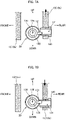
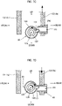
- FIG. 1A and FIG. 1B are explanatory diagrams illustrating the operation of the disc brake device 1.
- FIG. 1A and FIG. 1B are enlarged views of a main part of a disc brake device 1.
- FIG. 1A shows the disc brake device 1 in a braking state
- FIG. 1B shows the disc in a state in which braking is released.
- the plane including the front, rear, left and right directions is a horizontal plane, and the axis of rotation 100 of a brake disc 2 extends laterally.
- FIGS. 1A and 1B show front views when the disc brake device 1 placed on a horizontal plane is viewed from the longitudinal direction. Note that, in the drawings indicated below, the same or similar parts may be denoted by the same reference numerals and redundant description may be omitted. In some drawings, unnecessary symbols may be omitted from the description.
- a pair of brake levers (3L, 3R) extending upward are disposed opposite each other on the left and right sides of the brake disc 2.
- Brake linings (5L, 5R) are attached to the brake disc 2 via brake shoes 4 on extensions of each of the left and right brake levers (3L, 3R).
- the left and right brake levers (3L, 3R) have front and rear rotational shafts (31L, 31R) at the lower ends, and are linked via a linking mechanism (not shown) connected to the upper ends so as to swing out to the left and right.
- the linking mechanism is configured to be driven by a predetermined driving device.
- the left and right brake levers (3L, 3R) swing toward each other so that the brake linings (5L, 5R) close, sandwiching the brake disc 2 therebetween.
- the left and right brake levers (3L, 3R) swing away from each other and a gap (hereinafter, also referred to as a gap x) is generated between the brake disc 2 and the brake linings (5L, 5R) in the open state.
- Patent Document 1 Japanese Patent Laid-Open No. 11-37186 and US 6 112 861 A , belonging to the same family).
- Patent Document 1 describes a linking mechanism in a disc brake device, and the basic configuration and structure of the linking mechanism of the disc brake device according to the embodiment of the present invention is similar to that described in Patent Document 1.
- the structure and configuration of the linking mechanism of the disc brake device described in Patent Document 1 and the operation of these mechanisms is described.
- the rotational center in any rotation mechanism or the structure, parts, members, etc., for forming the rotational center of the rotation mechanism is referred to as an "axis of rotation" unless otherwise specified.
- FIGS. 2A , 2B are diagrams showing perspective views of the overall configuration of the disc brake device 1 when the disc brake device 1 is viewed from different directions.
- the disc brake device 1 includes various devices and mechanisms including the brake levers (3L, 3R) attached via various brackets fixed at appropriate positions on a base plate 6.
- the two brake levers (3L, 3R) are composed of two identical planar members facing front and rear, and the two planar members are connected via bolts 32 extending in the longitudinal direction.
- the lower ends of the brake levers (3L, 3R) are attached via separate rotary shafts (31L, 31R) provided to a single shared bracket 61.
- a linking mechanism 10 that swings the left and right brake levers (3L, 3R) so as to approach and separate from each other is disposed on the upper end side of the brake levers (3L, 3R).
- the linking mechanism 10 in the disc brake device 1 shown is composed of four planar levers (11a, 11b, 12a, 12b) having surfaces in vertical and horizontal directions and a rod-shaped coupling device 20 extending in the lateral direction at an angle.
- the four planar levers (11a, 11b, 12a, 12b) are fixed to each other by bolts 13 penetrating in the longitudinal direction and operate together as a single unit.
- the four levers (11a, 11b, 12a, 12b) have a pair of bent levers 11 that are extended over the left and right brake levers (3L, 3R) while facing each other in the longitudinal direction, and a pair of short levers 12 shorter in the lateral direction than the bent levers 11 while facing in the longitudinal direction.
- the short lever 12 attached to the brake lever 3R on the right side defines the respective directions of left and right, and when viewing the rear from the front, the front and rear directions are defined so that the left and right directions coincide with each other, such that the short lever 12 has a shape protruding downward with respect to the bent lever 11 and is attached to the front right side of the pair of bent levers 11.
- the four levers (11a, 11b, 12a, 12b) are formed so as to be L-shaped with the right end bent downward when viewed as a single unit.
- the pair of short levers 12 is disposed between the two front and rear planar lever members constituting the right brake lever 3R, and further, in the region below the bent lever 11, is pivotally supported by a rotary shaft 33 on the upper end side of the brake lever 3R.
- the rod-shaped coupling device 20 constituting the linking mechanism is extended towards the upper left from between the two short levers (12a, 12b) together with the bent lever 11 and the short lever 12.
- crosspieces (21, 22) having rotary shafts in the longitudinal direction are attached to the front end surface and the rear end surface of rectangular box-shaped block members, respectively.
- the crosspieces (21, 22) shown in the figure have a shape in which cylindrical shafts serving as rotary shafts (23, 24) protrude from the front and rear ends of rectangular box-shaped housings, and the rotary shaft 23 of the crosspiece 21 on the left end side is rotatably inserted into shaft holes formed in the upper ends of the two front and rear planar members constituting the left brake lever 3L.
- the rotary shaft 24 is rotatably inserted into shaft holes formed in the front and rear two short levers (12a, 12b).
- the position of the rotary shaft 24 of the right crosspiece 22 is located below the rotary shaft 33 for supporting the short lever 12 in the brake lever 3R on the right side.
- the vertical position where the left crosspiece 21 of the coupling device 20 is pivotally supported in the left brake lever 3L and the vertical position where the short lever 12 is pivotally supported in the right brake lever 3R are the same.
- the left and right brake levers (3L, 3R) swing so as to approach or separate from each other by interlocking with the linking mechanism 10 having the above-described configuration.
- the left end of the bent lever 11 is moved up and down by a predetermined power source, so that the left and right brake levers (3L, 3R) swing so as to be separated from and approach each other.
- a thruster 40 that raises the left end side of the bent lever 11 is used as a power source for operating the linking mechanism 10 to release the braking state of the brake disc 2.
- a spring mechanism 50 is used for maintaining the closed state when the thruster 40 is not operating.
- the thruster 40 is constituted by an electric actuator or the like, and when the thruster 40 is operated, a rod 41 extending in the vertical direction is extended upward.
- the thruster 40 has a rotary shaft 42 extending in the longitudinal direction at the lower end of the thruster 40, and is rotatably attached to a bracket 62 provided on the left rear side of the base plate 6, such that a slight swing in the lateral direction accompanying the operation of the linking mechanism 10 is allowed.
- a head 43 disposed between two front and rear bent levers (11a, 11b) is formed at the upper end of the rod 41 and has a rotary shaft 44 in the longitudinal direction and is pivotally supported by the left end of the bent lever 11.
- an appropriate rotation mechanism such as the above-described crosspiece can be used as a structure for pivotally supporting the head 43 with respect to the bent lever 11, an appropriate rotation mechanism such as the above-described crosspiece can be used.
- the spring mechanism 50 includes a hollow rectangular tube-shaped case 51 having a cylindrical axis in the vertical direction, a spring having a spiral axis in the vertical direction and housed in the housing, and a connection mechanism for transmitting to the linking mechanism 10 a later-described expansion/contraction motion of the spring.
- a lower end side the rectangular cylindrical case (hereinafter also referred to as the spring case 51) is attached to a bracket 63 provided on the rear of the base plate 6 in the vicinity of the center in the lateral direction.
- the spring case 51 is pivotally supported on the bracket 63 so as to be able to swing slightly in the lateral direction with the action on the linking mechanism 10.
- the bent lever 11 is always urged downward by a spring and a rod (not shown) housed in the spring case 51.
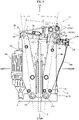
- FIG. 3 shows a front view of the disc brake device.
- the brake levers (3L, 3R) are generally swung so that the left and right brake levers (3L, 3R) are separated from and approach each other by moving the left end side of the bent lever 11 upward and downward.
- the thruster 40 when the thruster 40 is operated, the left end of the bent lever 11 rises against the downward biasing force of the spring mechanism 50 (s1).
- the bent lever 11 and the short lever 12 are together rotated clockwise with the rotary shaft 33 of the short lever 12 pivotally supported by the right brake lever 3R as a fulcrum (s2).
- the coupling device 20 Since the right end of the coupling device 20 is pivotally supported at a position below the rotary shaft 33 of the short lever 12, the coupling device moves to the left as the bent lever 11 and the short lever 12 rotate (s3). Since the left end of the coupling device 20 is pivotally supported by the upper end of the left brake lever 3L, the upper end of the left brake lever 3L is urged to the left (s4). As a result, the right lever 3R also receives a reaction force and swings to the right. That is, the brake levers (3L, 3R) are swung away from each other (s5), and the disc brake device 1 is in the open state in which the braking state is released.
- the left and right brake levers (3L, 3R) swing toward each other (s16), the brake disc 2 is sandwiched between the brake linings (5L, 5R) attached to the brake levers (3L, 3R) via the brake shoe 4, and the disc brake device 1 is in the closed state.
- the included angle ⁇ between the left and right brake levers (3L, 3R) in the closed state gradually decreases. That is, the left end of the bent lever 11 in the closed state gradually falls downward. If wear progresses and the rod 41 of the thruster 40 descends to the bottom dead center, the angle ⁇ between the left and right brake levers (3L, 3R) cannot be reduced. For this reason, the frictional force when the rotating brake disc 2 is sandwiched by the brake linings (5L, 5R) decreases, and there is a possibility that the brake disc 2 cannot be reliably operated.
- the disc brake device described in Patent Document 1 is provided with an automatic wear adjustment device (hereinafter also referred to as an AWA device) that automatically adjusts the distance between the left and right brake levers in the braking state depending on the state of wear of the brake linings so that the rod thruster does not reach the bottom dead center even when the brake linings are worn.
- the AWA operates to gradually shorten the length of the coupling device as the brake linings gradually wear out, thereby reducing the included angle between the left and right brake levers in the open state while maintaining a constant difference between the left and right brake levers in the each of the open state and the closed state.
- the AWA mechanism and configuration are described in detail in Patent Document 1.
- the disc brake device described in Patent Document 1 also includes a mechanism for rotating the left and right brake levers symmetrically about the brake disc.
- the AWA is designed to maintain a constant angle between the left and right brake levers in the open state and the closed state, and the left and right brake levers do not always swing symmetrically about the brake disc.
- the disc brake device described in Patent Document 1 is provided with an Automatic Wear Centering Device (hereinafter also referred to as ACD) on the lower end of the right side of the lever so that the right and left brake levers are automatically adjusted so as to swing symmetrically toward the brake disc device.
- ACD Automatic Wear Centering Device
- the ACD is covered with a box-like cover 7 disposed below the right brake lever 3R in the disc brake device 1 shown in FIG 2 .
- FIG. 4 is an enlarged perspective view of the lower right side of the disc brake device 1, and shows a state in which the cover 7 covering the ACD is removed.
- the main body of the ACD 70 is a rack and pinion 71 installed on the lower end side of the right brake lever 3R, and a male screw is formed around the vertical axis.
- a pinion 73 is attached to the upper end side of an adjustment bolt 72.
- the male screw of the adjustment bolt 72 is screwed from above into a block-like member (hereinafter also referred to as a stopper 74) that protrudes toward the right outer side at the lower end of the right brake lever 3R, and its lower end protrudes below the stopper 74.
- a pedestal 75 for receiving the lower end of the adjustment bolt 72 is provided immediately below the stopper 74.
- the bracket 61 that pivotally supports the lower ends of the left and right brake levers (3L, 3R) also serves as the aforementioned pedestal 75.
- the operating principle of the ACD 70 is that, when the adjustment bolt 72 is rotated in the screwing direction, the lower end of the adjustment bolt 72 is brought into contact with the pedestal 75 in the open state to restrict the swinging of the right brake lever 3R to the right. Then, the swinging of the left brake lever ( FIG. 2 , reference numeral 3L) coupled to the right brake lever 3R via the linking mechanism ( FIG. 4 , reference numeral 10) is also restricted, and the left and right brake levers (3L, 3R) are adjusted to be symmetrical with respect to the brake disc ( FIG. 2 , reference numeral 2).
- the pinion 73 is attached to the upper end of the adjustment bolt 72 through a one-way clutch. If the adjustment bolt 72 is a right-handed thread, and if the pinion 73 is rotated in the clockwise direction when viewed from above, then the adjustment bolt 72 rotates in a direction to be screwed in via the one-way clutch. In the counterclockwise direction, the one-way clutch rotates idly, and the adjustment bolt 72 does not rotate and the length of the bolt 72 protruding below the stopper 74 is maintained. On the other hand, the rack 76 that meshes with the pinion 73 is fixed to the base plate 6.
- FIGS. 5A-5D illustrate schematically the operation of the ACD, showing a top view when the rack and pinion 71 which comprises the ACD is seen from above.
- the position of the pinion 73 relative to the rack 76 in the lateral direction changes as indicated by the thick line arrows. If the brake linings are not in a worn condition, the relative displacement is within backlash W. Accordingly, when there is no wear on the brake linings, the pinion 73 does not rotate and the adjustment bolt 72 does not rotate.
- the lower end of the adjustment bolt 72 protrudes beyond the stopper and comes into contact with the upper surface of the pedestal at a stage when the rightward swinging angle of the right brake lever is smaller. That is, the right brake lever is prevented from tilting excessively to the right.
- the disc brake device described in Patent Documents 1 and 2 is equipped with AWA and ACD and can maintain a constant, lateral symmetrical distance between the brake disc and the brake linings even as the brake linings wear down.
- the surface of the brake disc is not necessarily perpendicular to the axis of rotation over the entire surface of the disc. Even if it is very slight, there are many cases where the surface of the brake disc has minute irregularities and undulations, and the angle between the rotary shaft and the surface of the brake disc is not 90°. As a result, the position of the surface of the brake disc with which the brake linings come into contact changes every time the brake disc is closed.
- the inclination of the left and right brake levers is slightly displaced in the lateral direction depending on the rotational position of the brake disc in the closed state. If the displacement exceeds the backlash allowed in the ACD, there is a possibility that the ACD malfunctions and unnecessarily rotates in the direction in which the adjustment bolt is screwed. As a result, the left and right brake levers cannot be opened and closed symmetrically.
- a disc brake device that sandwiches a brake disc between left and right brake linings disposed opposite and facing each other across the brake disc in a lateral direction to brake the rotation of the brake disc, the disc brake device comprising:
- the left and right brake levers in the closed state are generally tilted to the left and the right brake lining is partially reduced.
- the open state if the left and right brake levers are generally tilted to the left, the right brake lining may touch the surface of the brake disc, which is not necessarily a flat surface. If the brake lining touches the rotating brake disc it may destabilize the operation of the driven body to be braked that is rotating the brake disc.
- the present invention has to solve the objective technical problem of providing a disc brake device that can maintain a constant difference in the included angle between the left and right brake levers as between the operating state and the state of release the even as the brake linings wear down, and moreover keep the brake levers laterally symmetrical about the brake disc.
- one aspect of the present invention provides a disc brake device that sandwiches a brake disc between left and right brake linings disposed opposite and facing each other across the brake disc in the lateral direction to brake the rotation of the brake disc, with the disc brake device comprising:
- the disc brake device may be one in which the flexible shaft is a coil-type flexible shaft.
- the flexible shaft may be a universal joint-type flexible shaft.
- a transmission gear may be interposed between the flexible shaft and the spindle.
- the automatic gap distribution apparatus may cause the adjustment bolt to protrude downward relative to the stopper as the spindle rotates by a predetermined angle according to a ratio between the pitch of the spindle and the pitch of the adjustment bolt.
- the disc brake device may be provided with a gear mechanism for converting an axis of rotation of the spindle into an axis of rotation extending downward.
- the disc brake device of the present invention even if the brake linings wear down, the difference of the included angle between the left and right brake levers between the state of release and during braking, and the brake levers can be kept symmetrical with respect to the brake disc. Other effects will become clear from the following description.
- the disc brake device In the conventional disc brake device, even if the opening/closing angle of the brake lever is kept constant by the AWA, there is a possibility that the corrected state of the tilt of the brake levers adjusted by the ACD becomes corrupted in the process of operating the disc brake device. Therefore, the disc brake device according to the embodiment of the present invention has a structure based on the technical concept that, once the inclination of the brake lever is adjusted by the ACD, the adjustment state of the inclination is maintained unless the opening/closing angle of the brake lever is readjusted by the AWA.
- the basic configuration of the disc brake device according to the embodiment of the present invention is the same as the disc brake device described in Patent Documents 1 and 2 or Non-Patent Documents 1 and 2, and the configuration and structure of the AWA are also substantially the same as those described in the literature.
- the mechanisms and structure of the AWA it becomes possible to eliminate malfunctioning of the ACD.
- the mechanism and operation of the AWA is described in detail, and then the configuration, structure, and operation of the disc brake according to the present embodiment is described.
- FIG. 6 is a diagram illustrating a coupling device that operates as an AWA.
- the figure is a view of the rod-shaped coupling device 20 as viewed from a direction orthogonal to the axis, and corresponds to the direction of arrows a-a in FIG. 3 .
- a part of the coupling device 20 shown in the figure is shown as a cross-section along a plane including the shaft so that the structure can be easily understood.
- the cross-section corresponds to the cross-section along the line b-b in FIG. 3 , and the cross-section is shown by hatching.
- the right end is the base end and the left end is the front end.
- the coupling device 20 includes a spindle 120 having a male screw 121 formed around the periphery of the front end of the spindle 120.
- the male screw 121 on the front end of the spindle 120 is screwed into a female screw 123 formed on the inner surface of a sleeve (hereinafter also referred to as a threaded sleeve 122) disposed on the front end of the spindle 120.
- a threaded sleeve 122 disposed on the front end of the spindle 120.
- a crosspiece 21 that projects in the longitudinal direction is attached to the threaded sleeve 122, and the front end side of the coupling device 20 is pivotally supported by the upper end of the left brake lever 3L via the crosspiece 21.
- a hollow cylindrical sleeve (hereinafter also referred to as a protective sleeve 124) is connected to the base end side of the threaded sleeve 122, and an intermediate portion in the long direction of the spindle 120 is supported by the protective sleeve 124.
- the spindle 120 extends from the front end side inserted into the threaded sleeve 122 through the hollow portion of the protective sleeve 124 and obliquely downward to the right to the base end.
- the spindle 120 is inserted into a sleeve (hereinafter also referred to as a thrust sleeve 125) separate from the previous two sleeves (122, 124) on the way to the base end.
- a crosspiece 22 similar to the crosspiece 21 attached to the threaded sleeve 122 is connected to the base end side of the thrust sleeve 125.
- the crosspiece 22 is pivotally supported by the short lever 12.
- the spindle 120 is inserted into the crosspiece 22 via the thrust sleeve 125 and protrudes further to the right and beyond the base end side of the crosspiece 22.
- the one-way clutch 130 is mounted on the protruding portion of the spindle 120 so as to be coaxial with an axis of rotation of the spindle 120.
- An engagement pin 131 composed of a spring pin is attached to the one-way clutch 130 so as to protrude radially outward with respect to the axis of rotation 126.
- a collar stop 140 that accommodates the engaging pin 131 in a loosely fitted state is attached to one of the two short levers (12a, 12b) facing front and rear.
- the collar stop 140 is attached to the rear short lever 12b.
- the collar stop 140 has a hollow cylindrical shape with the longitudinal direction as an axis, and an end surface on the engagement pin 131 side is open. The front end side of the engagement pin 131 is inserted into a hollow portion 141 of the collar stop 140 from the opening.
- the diameter of the engaging pin 131 is about 1/3 of the inner diameter of the hollow portion 141 of the collar stop 140.
- the spindle 120 when viewed from the base end toward the front end, when the one-way clutch 130 rotates in the clockwise direction, the spindle 120 also rotates in the same direction. When rotating in the counterclockwise direction, the one-way clutch 130 idles with respect to the spindle 120 and the spindle 120 is not rotated around the axis of rotation.
- FIGS. 7A to 7D illustrate the principle of operation of the AWA.
- FIGS. 7A to 7D schematically illustrate a state in which the coupling device 20 and the short lever 12 are viewed from the right side. It should be noted that FIGS. 7A to 7D illustrate the operating states of different AWAs. In the following description, the operation of the AWA is described with reference to FIGS. 7A to 7D and FIGS. 3 and 6 described above.
- the short lever 12 is pivotally supported by the upper rotary shaft ( FIG. 3 , reference numeral 33) of the right brake lever ( FIG. 3 , reference numeral 3R) and swings about the rotary shaft 33 as a single unit together with the bent lever ( FIG. 3 , reference numeral 11).
- the collar stop 140 is attached to the short lever 12, so that, when viewed from the front, the collar stop 140 traces an arc-shaped trajectory centering on the rotary shaft 33 as the short lever 12 swings. That is, when viewed from the right, the collar stop 140 reciprocates in the vertical direction.
- the included angle ⁇ of the left and right brake levers (3L, 3R) shown in FIG. 3 is narrowed in the open state, and the gap between the brake disc 2 and the brake linings (5L, 5R) decreases, with the result that the braking force applied to the brake disc 2 in the closed state is maintained in the same manner as before the brake linings (5L, 5R) are worn.
- the disc brake device of this embodiment is characterized by a mechanism that directly links the AWA and the ACD.
- the AWA operates by the same mechanism as that of the conventional disc brake device.
- the principle for adjusting the gap itself is the same as that of the conventional ACD. That is, by adjusting the length of the adjustment bolt protruding below the stopper by rotating the adjustment bolt, the left and right brake levers are adjusted so as to swing symmetrically about the brake disc.
- the mechanism for rotating the adjustment bolt in the ACD is not a rack and pinion but a mechanism that is directly linked to the rotary motion of the spindle in the AWA.
- FIG. 8 shows a disc brake device 1a according to an embodiment of the present invention.
- the disc brake device 1a transmits the rotary motion of the spindle 120, which rotates about the direction of extension of the coupling device 20 as the axis of rotation, to the adjustment bolt 72 via a flexible shaft 150.
- the flexible shaft 150 is a shaft that can transmit rotary motion while freely changing direction.
- a flexible shaft called a "coil-shaped flexible shaft” or “flexible shaft” (hereinafter also referred to as the flexible shaft 150) is used.
- the flexible shaft 150 has, for example, a structure in which a thin wire and a thick wire are sequentially wound in a reverse winding in a coil shape from the interior toward the exterior.
- a gear box 160 incorporating a bevel gear is connected to the base end of the spindle 120, and one end of the flexible shaft 150 is connected to an output shaft 161 of the gear box 160.
- the adjustment bolt 72 is connected to the upper end.
- the bevel gear in the gear box 160 is a reduction gear, and the output shaft 161 is rotated so that the rotation angle is a predetermined ratio with respect to the rotation angle input from the spindle 120, such that the adjustment bolt 72 is rotated by just that rotation angle.
- the flexible shaft 150 rotates the adjustment bolt 72 counterclockwise when viewed from above.
- the male screw of the Adjustment bolt 72 and the female screw of the stopper 74 are left-handed screws.
- the disc brake device 1a relies mainly on the flexible shaft 150, the speed reduction ratio of the gear box 160, the thread pitch of the male screw formed around the circumference of the spindle 120, the adjustment bolt 72 pitch, the screw direction of the spindle 120 and the adjustment bolt 72 (right screw, left screw) and the like to provide the ACD function.
- the flexible shaft 15 directly transmits the rotational movement of the spindle 120 accompanying the operation of the AWA to the adjustment bolt 72 to rotate the adjustment bolt 72. Since the spindle 120 rotates only in one direction by the above-described operation of the AWA, the adjustment bolt 72 does not rotate in a direction that returns the screw.
- the adjustment bolt 72 does not rotate unless the spindle 120 rotates in a direction that shortens the total length D of the coupling device 20. Therefore, the ACD does not malfunction even if the surface of the brake disc 2 has undulations or unevenness.
- the timing at which the ACD operates is the timing at which the AWA operates to enter a closed state.
- the right brake lever 3R fixing the stopper 74 in place is swung to the left, and the lower end of the adjustment bolt 72 screwed to the stopper 74 is either floating or is not pushed hard against the pedestal 75. That is, the adjustment bolt 72 can be easily rotated. Therefore, the adjustment bolt 72 is rotated reliably and accurately by the rotational torque of the flexible shaft 150. As a result, the gap is automatically adjusted with extremely high accuracy and maintained in that state.
- the total length D of the coupling device 20 shortened according to the reduction ratio in the gear box 160 and the state of wear of the brake linings (5L, 5R), the angle ⁇ of the left and right brake levers (3L, 3R) in the closed state and the open state according to that length, the pitch of the male screw formed on the outer periphery of the spindle 120, and the pitch of the adjustment bolt 72, can all be changed as appropriate.
- FIG. 9 is an explanatory diagram relating to the dimensions and angles of each part of the disc brake device 1a.
- FIG. 9 is a front view of the disc brake device 1a according to the present embodiment as viewed from the front. In the drawing, the dimensions of each part are indicated by various symbols.
- the vertical distance from the rotary shafts (31L, 31R) of the brake levers (3L, 3R) to the vertical center position of the brake linings (5L, 5R) is A
- the vertical distance from the center position of the brake linings (5L, 5R) to the vertical position where the crosspiece 21 on the front end side of the coupling device 20 is pivotally supported by the left brake lever 3L is B
- the distance in the lateral direction from the rotary shaft 31R of the right brake lever 3R to the lower end of the adjustment bolt 72 is C.
- the angle of inclination of the coupling device 20 with respect to the horizontal direction parallel to the horizontal plane is ⁇
- the pitch of the spindle 120 is P1
- the pitch of the adjustment bolts 72 is P2.
- the above-described AWA adjusts the total length D of the coupling device 20 so as to keep the angle of inclination ⁇ constant according to the wear of the brake linings (5L, 5R).
- each part of the disc brake device 1 illustrated in FIGS. 8 and 9 (A, B, C, ⁇ , P1, P2) and the rotation angle that is the difference of the included angle ⁇ between the open and closed states, the reduction ratio of the gear box 160, and the length by which the adjustment bolt 72 is screwed in from a state in which the brake linings (5L, 5R) are not worn to a worn state that requires replacement of the brake linings (5L, 5R) can be designed as appropriate.
- the dimensions, angles, pitches, reduction ratios, and the like of the above portions are set as appropriate, and when the thicknesses in the left and right directions of each of the brake linings (5L, 5R) is worn down, the distance between the brake pads (5L, 5R) and the brake disc 2 in the open state can be reduced by an amount equivalent to the reduction in thickness due to wear.
- the direction of the axis of rotation of the spindle is changed to a substantially vertical direction using a bevel gear.
- the flexible shaft may be directly mounted to the rotary shaft of the spindle, or the flexible shaft may be curved downward while extended along the length of the direction of the axis of rotation and connected to the adjustment bolt.
- a non-flexible shaft such as a metal shaft can be attached to the output shaft and adjustment bolt of the gear box, and the flexible shaft can be connected to the tip of the shaft.
- the adjustment bolt can be rotated by the rotation of the spindle even if the relative positions of each part may change with the opening/closing operation of the disc brake device.
- the flexible shaft is not limited to a flexible shaft as such, and may comprise a universal joint-type flexible shaft connected by a short rigid shaft (also called a universal joint).
- a flexible shaft in which a flexible shaft and a universal joint-type flexible shaft are combined may be used.
- an appropriate flexible shaft can be adopted according to the installation environment of the disc brake device, the manufacturing cost, the durability required for the flexible shaft, and the like.
- gear mechanism in addition to various bevel gears (such as a bevel gear, a spiral bevel gear, a Zerol bevel gear, etc.), a face gear, a high void gear, etc., can be used as the gear mechanism for converting the axis of rotation of the spindle into an axis of rotation extending downward.
- bevel gears such as a bevel gear, a spiral bevel gear, a Zerol bevel gear, etc.
- a face gear such as a bevel gear, a spiral bevel gear, a Zerol bevel gear, etc.
- a high void gear etc.
- a single gear mechanism may be a combination of a plurality of different gear mechanisms.
- the adjustment bolt since the pitch of the adjustment bolt used is too large, when the adjustment bolt and the spindle rotate by the same rotation angle, the adjustment bolt protrudes excessively downward with respect to the stopper. Therefore, the difference in the rotation angle between the spindle and the adjustment bolt is adjusted by the reduction ratio of the gear of the gear box so that when the spindle rotates by a predetermined angle, the adjustment bolt protrudes for a predetermined length with respect to the stopper.
- the gear ratio in the gearbox is constant, if the ratio between the pitch of the spindle and the pitch of the adjustment bolt is set appropriately, when the spindle has rotated by a predetermined rotation angle the adjustment bolt can be protruded downward with respect to the stopper by a desired length.
- the gear ratio of the gearbox is 1 ⁇ 2
- the gear ratio may be set to 1 and the pitch of the adjustment bolts may be halved.
- multiple threads may be employed on the spindle and the control bolt.
- the pitch of one of the spindle and the adjustment bolt may become excessive.
- the pitch becomes excessive the dimensions of the external threads of the spindle and the adjustment bolt and the thread of the internal thread that is the counterpart to these external threads become large. If the thread becomes large, it becomes difficult to machine the screw accurately. Furthermore, in order to form a large thread, it is necessary to cut a large volume, which increases the time and cost required for machining.
- the spindle is also a part of the linking mechanism and must be sufficiently strong.
- the threaded sleeve female thread that is the counterpart to the male thread of the spindle is also thin if the outer diameter is the same. Therefore, in particular, it is difficult to adopt a single-thread screw having a large pitch, which might well have insufficient strength, for the male screw of the spindle and the female screw of the threaded sleeve.
- the pitch can be reduced while maintaining the leads so as to ensure machining accuracy and sufficient strength.
- the number of threads of the multi-thread can be set as appropriate according to the ratio between the lead of the spindle and the lead of the adjustment bolt or the machining accuracy.
- the disc brake device only requires a configuration in which, when the spindle rotates by a predetermined rotation angle, the adjustment bolt is screwed via the flexible shaft and proceeds downward for a predetermined length.
- the spindle is a right-handed thread and the adjustment bolt is a left-handed thread, so that when the spindle rotates in the direction of shortening the coupling device, the adjustment bolt rotates in the direction to be screwed into the stopper and the lower end side of the adjustment bolt protrudes further downward with respect to the stopper.
- the flexible shaft may be rotated in a state in which the direction of rotation of the spindle is reversed using the gear. In doing so, an ordinary right-handed thread can be used for the adjustment bolt.
Landscapes
- Engineering & Computer Science (AREA)
- General Engineering & Computer Science (AREA)
- Mechanical Engineering (AREA)
- Transportation (AREA)
- Physics & Mathematics (AREA)
- Electromagnetism (AREA)
- Braking Arrangements (AREA)
- Transmission Devices (AREA)
Description
- This patent application is based on and claims priority to
Japanese Patent Application Nos. 2017-118666, filed on June 16, 2017 2017-1197147, filed on October 10, 2017 - The present invention relates to a disc brake device for heavy equipment such as hoists.
- A disc brake generates braking force by sandwiching both front and rear surfaces of a rotary brake disc connected to a driven body (for example, a wheel, a belt, etc.) to be braked with brake linings as a friction material.
FIG. 1A andFIG. 1B are explanatory diagrams illustrating the operation of thedisc brake device 1.FIG. 1A andFIG. 1B are enlarged views of a main part of adisc brake device 1.FIG. 1A shows thedisc brake device 1 in a braking state, andFIG. 1B shows the disc in a state in which braking is released. In the following description, it is assumed that the plane including the front, rear, left and right directions is a horizontal plane, and the axis of rotation 100 of abrake disc 2 extends laterally.FIGS. 1A and1B show front views when thedisc brake device 1 placed on a horizontal plane is viewed from the longitudinal direction. Note that, in the drawings indicated below, the same or similar parts may be denoted by the same reference numerals and redundant description may be omitted. In some drawings, unnecessary symbols may be omitted from the description. - As illustrated in
FIGS. 1A and1B , a pair of brake levers (3L, 3R) extending upward are disposed opposite each other on the left and right sides of thebrake disc 2. Brake linings (5L, 5R) are attached to thebrake disc 2 viabrake shoes 4 on extensions of each of the left and right brake levers (3L, 3R). The left and right brake levers (3L, 3R) have front and rear rotational shafts (31L, 31R) at the lower ends, and are linked via a linking mechanism (not shown) connected to the upper ends so as to swing out to the left and right. The linking mechanism is configured to be driven by a predetermined driving device. - As illustrated in
FIG. 1A , in the braking state, the left and right brake levers (3L, 3R) swing toward each other so that the brake linings (5L, 5R) close, sandwiching thebrake disc 2 therebetween. When the braking state is released, as illustrated inFIG. 1B , the left and right brake levers (3L, 3R) swing away from each other and a gap (hereinafter, also referred to as a gap x) is generated between thebrake disc 2 and the brake linings (5L, 5R) in the open state. - As a prior art document of the present invention, there is Patent Document 1 (
Japanese Patent Laid-Open No. 11-37186 US 6 112 861 A , belonging to the same family).Patent Document 1 describes a linking mechanism in a disc brake device, and the basic configuration and structure of the linking mechanism of the disc brake device according to the embodiment of the present invention is similar to that described inPatent Document 1. Below, in order to further an understanding of the present invention, the structure and configuration of the linking mechanism of the disc brake device described inPatent Document 1 and the operation of these mechanisms is described. For ease of comprehension, the rotational center in any rotation mechanism or the structure, parts, members, etc., for forming the rotational center of the rotation mechanism is referred to as an "axis of rotation" unless otherwise specified. -
FIGS. 2A ,2B are diagrams showing perspective views of the overall configuration of thedisc brake device 1 when thedisc brake device 1 is viewed from different directions. As illustrated inFIGS. 2A and2B , thedisc brake device 1 includes various devices and mechanisms including the brake levers (3L, 3R) attached via various brackets fixed at appropriate positions on abase plate 6. The two brake levers (3L, 3R) are composed of two identical planar members facing front and rear, and the two planar members are connected viabolts 32 extending in the longitudinal direction. The lower ends of the brake levers (3L, 3R) are attached via separate rotary shafts (31L, 31R) provided to a single sharedbracket 61. A linkingmechanism 10 that swings the left and right brake levers (3L, 3R) so as to approach and separate from each other is disposed on the upper end side of the brake levers (3L, 3R). - The linking
mechanism 10 in thedisc brake device 1 shown is composed of four planar levers (11a, 11b, 12a, 12b) having surfaces in vertical and horizontal directions and a rod-shaped coupling device 20 extending in the lateral direction at an angle. The four planar levers (11a, 11b, 12a, 12b) are fixed to each other bybolts 13 penetrating in the longitudinal direction and operate together as a single unit. The four levers (11a, 11b, 12a, 12b) have a pair ofbent levers 11 that are extended over the left and right brake levers (3L, 3R) while facing each other in the longitudinal direction, and a pair ofshort levers 12 shorter in the lateral direction than the bent levers 11 while facing in the longitudinal direction. - Here, as illustrated in the figure, the
short lever 12 attached to thebrake lever 3R on the right side defines the respective directions of left and right, and when viewing the rear from the front, the front and rear directions are defined so that the left and right directions coincide with each other, such that theshort lever 12 has a shape protruding downward with respect to thebent lever 11 and is attached to the front right side of the pair ofbent levers 11. Accordingly, the four levers (11a, 11b, 12a, 12b) are formed so as to be L-shaped with the right end bent downward when viewed as a single unit. The pair ofshort levers 12 is disposed between the two front and rear planar lever members constituting theright brake lever 3R, and further, in the region below thebent lever 11, is pivotally supported by arotary shaft 33 on the upper end side of thebrake lever 3R. - The rod-
shaped coupling device 20 constituting the linking mechanism is extended towards the upper left from between the two short levers (12a, 12b) together with thebent lever 11 and theshort lever 12. At both the left and right ends of thecoupling device 20, crosspieces (21, 22) having rotary shafts in the longitudinal direction are attached to the front end surface and the rear end surface of rectangular box-shaped block members, respectively. The crosspieces (21, 22) shown in the figure have a shape in which cylindrical shafts serving as rotary shafts (23, 24) protrude from the front and rear ends of rectangular box-shaped housings, and therotary shaft 23 of thecrosspiece 21 on the left end side is rotatably inserted into shaft holes formed in the upper ends of the two front and rear planar members constituting theleft brake lever 3L. Therotary shaft 24 is rotatably inserted into shaft holes formed in the front and rear two short levers (12a, 12b). - The position of the
rotary shaft 24 of theright crosspiece 22 is located below therotary shaft 33 for supporting theshort lever 12 in thebrake lever 3R on the right side. The vertical position where theleft crosspiece 21 of thecoupling device 20 is pivotally supported in theleft brake lever 3L and the vertical position where theshort lever 12 is pivotally supported in theright brake lever 3R are the same. The left and right brake levers (3L, 3R) swing so as to approach or separate from each other by interlocking with the linkingmechanism 10 having the above-described configuration. In general, the left end of thebent lever 11 is moved up and down by a predetermined power source, so that the left and right brake levers (3L, 3R) swing so as to be separated from and approach each other. In the illustrateddisc brake device 1, athruster 40 that raises the left end side of thebent lever 11 is used as a power source for operating the linkingmechanism 10 to release the braking state of thebrake disc 2. Aspring mechanism 50 is used for maintaining the closed state when thethruster 40 is not operating. - The
thruster 40 is constituted by an electric actuator or the like, and when thethruster 40 is operated, arod 41 extending in the vertical direction is extended upward. Thethruster 40 has arotary shaft 42 extending in the longitudinal direction at the lower end of thethruster 40, and is rotatably attached to abracket 62 provided on the left rear side of thebase plate 6, such that a slight swing in the lateral direction accompanying the operation of the linkingmechanism 10 is allowed. Ahead 43 disposed between two front and rear bent levers (11a, 11b) is formed at the upper end of therod 41 and has arotary shaft 44 in the longitudinal direction and is pivotally supported by the left end of thebent lever 11. In addition, as a structure for pivotally supporting thehead 43 with respect to thebent lever 11, an appropriate rotation mechanism such as the above-described crosspiece can be used. - The
spring mechanism 50 includes a hollow rectangular tube-shaped case 51 having a cylindrical axis in the vertical direction, a spring having a spiral axis in the vertical direction and housed in the housing, and a connection mechanism for transmitting to the linking mechanism 10 a later-described expansion/contraction motion of the spring. A lower end side the rectangular cylindrical case (hereinafter also referred to as the spring case 51) is attached to abracket 63 provided on the rear of thebase plate 6 in the vicinity of the center in the lateral direction. Like thethruster 40, thespring case 51 is pivotally supported on thebracket 63 so as to be able to swing slightly in the lateral direction with the action on the linkingmechanism 10. Thebent lever 11 is always urged downward by a spring and a rod (not shown) housed in thespring case 51. - Next, the operation of the brake lever via the linking
mechanism 10 is described.FIG. 3 shows a front view of the disc brake device. The brake levers (3L, 3R) are generally swung so that the left and right brake levers (3L, 3R) are separated from and approach each other by moving the left end side of thebent lever 11 upward and downward. Specifically, as shown by the black arrow inFIG. 3 , when thethruster 40 is operated, the left end of thebent lever 11 rises against the downward biasing force of the spring mechanism 50 (s1). As the left end of thebent lever 11 rises, thebent lever 11 and theshort lever 12 are together rotated clockwise with therotary shaft 33 of theshort lever 12 pivotally supported by theright brake lever 3R as a fulcrum (s2). - Since the right end of the
coupling device 20 is pivotally supported at a position below therotary shaft 33 of theshort lever 12, the coupling device moves to the left as thebent lever 11 and theshort lever 12 rotate (s3). Since the left end of thecoupling device 20 is pivotally supported by the upper end of theleft brake lever 3L, the upper end of theleft brake lever 3L is urged to the left (s4). As a result, theright lever 3R also receives a reaction force and swings to the right. That is, the brake levers (3L, 3R) are swung away from each other (s5), and thedisc brake device 1 is in the open state in which the braking state is released. - On the other hand, when the thruster is put into the non-operating state by powering down or the like, as indicated by the whited-out arrows in the figure the
bent lever 11 connected to the upper end of the rod of thespring mechanism 50 is biased downward (s11), therod 41 of thethruster 40 is lowered (s12), and thebent lever 11 and theshort lever 12 are together rotated counterclockwise with therotary shaft 33 of theshort lever 12 as a fulcrum. (s13). As the levers (11, 12) rotate, the right end of thecoupling device 20 is pushed to the right (s14) and the upper end of theleft brake lever 3L that pivotally supports the left end of thecoupling device 20 is urged to the right (s15). As a result, the left and right brake levers (3L, 3R) swing toward each other (s16), thebrake disc 2 is sandwiched between the brake linings (5L, 5R) attached to the brake levers (3L, 3R) via thebrake shoe 4, and thedisc brake device 1 is in the closed state. - However, in the
disc brake device 1 having theaforementioned linking mechanism 10, as the brake linings (5L, 5R) wear out the distances between the left and right brake levers (3L, 3R) in the closed state gradually decreases. Therefore, the included angle α between the left and right brake levers (3L, 3R) in the closed state gradually decreases. That is, the left end of thebent lever 11 in the closed state gradually falls downward. If wear progresses and therod 41 of thethruster 40 descends to the bottom dead center, the angle α between the left and right brake levers (3L, 3R) cannot be reduced. For this reason, the frictional force when therotating brake disc 2 is sandwiched by the brake linings (5L, 5R) decreases, and there is a possibility that thebrake disc 2 cannot be reliably operated. - Thus, the disc brake device described in
Patent Document 1 is provided with an automatic wear adjustment device (hereinafter also referred to as an AWA device) that automatically adjusts the distance between the left and right brake levers in the braking state depending on the state of wear of the brake linings so that the rod thruster does not reach the bottom dead center even when the brake linings are worn. The AWA operates to gradually shorten the length of the coupling device as the brake linings gradually wear out, thereby reducing the included angle between the left and right brake levers in the open state while maintaining a constant difference between the left and right brake levers in the each of the open state and the closed state. The AWA mechanism and configuration are described in detail inPatent Document 1. - Further, the disc brake device described in
Patent Document 1 also includes a mechanism for rotating the left and right brake levers symmetrically about the brake disc. In general, when the length of the coupling device is shortened by the AWA and the angle between the left and right brake levers in the open state becomes narrower, the downward biasing force of the spring acts asymmetrically in the lateral direction on the linking mechanism and in some cases, the left and right brake levers are tilted toward the right brake lever as a whole. In other words, the AWA is designed to maintain a constant angle between the left and right brake levers in the open state and the closed state, and the left and right brake levers do not always swing symmetrically about the brake disc. When the left and right brake levers as a whole are tilted toward one brake lever or the other, the brake linings are reduced lopsidedly. Since it is necessary to replace the brake linings with a left and right pair, the frequency of replacement of the brake linings increases, as does the cost of maintenance. - Therefore the disc brake device described in
Patent Document 1 is provided with an Automatic Wear Centering Device (hereinafter also referred to as ACD) on the lower end of the right side of the lever so that the right and left brake levers are automatically adjusted so as to swing symmetrically toward the brake disc device. The ACD is covered with a box-like cover 7 disposed below theright brake lever 3R in thedisc brake device 1 shown inFIG 2 .FIG. 4 is an enlarged perspective view of the lower right side of thedisc brake device 1, and shows a state in which the cover 7 covering the ACD is removed. - As illustrated in
FIG. 4 , the main body of theACD 70 is a rack andpinion 71 installed on the lower end side of theright brake lever 3R, and a male screw is formed around the vertical axis. Apinion 73 is attached to the upper end side of anadjustment bolt 72. The male screw of theadjustment bolt 72 is screwed from above into a block-like member (hereinafter also referred to as a stopper 74) that protrudes toward the right outer side at the lower end of theright brake lever 3R, and its lower end protrudes below thestopper 74. - On the
base plate 6, a pedestal 75 for receiving the lower end of theadjustment bolt 72 is provided immediately below thestopper 74. In this example, thebracket 61 that pivotally supports the lower ends of the left and right brake levers (3L, 3R) also serves as the aforementioned pedestal 75. The operating principle of theACD 70 is that, when theadjustment bolt 72 is rotated in the screwing direction, the lower end of theadjustment bolt 72 is brought into contact with the pedestal 75 in the open state to restrict the swinging of theright brake lever 3R to the right. Then, the swinging of the left brake lever (FIG. 2 ,reference numeral 3L) coupled to theright brake lever 3R via the linking mechanism (FIG. 4 , reference numeral 10) is also restricted, and the left and right brake levers (3L, 3R) are adjusted to be symmetrical with respect to the brake disc (FIG. 2 , reference numeral 2). - In the
ACD 70, to automatically adjust the position of the brake levers (3L, 3R) according to the above-described principle, thepinion 73 is attached to the upper end of theadjustment bolt 72 through a one-way clutch. If theadjustment bolt 72 is a right-handed thread, and if thepinion 73 is rotated in the clockwise direction when viewed from above, then theadjustment bolt 72 rotates in a direction to be screwed in via the one-way clutch. In the counterclockwise direction, the one-way clutch rotates idly, and theadjustment bolt 72 does not rotate and the length of thebolt 72 protruding below thestopper 74 is maintained. On the other hand, therack 76 that meshes with thepinion 73 is fixed to thebase plate 6. Then, when the left and right brake levers (3L, 3R) are opened and closed in the lateral direction in accordance with movement to the open state and the closed state in thedisc brake device 1, thepinion 73 is engaged with thestopper 74 by meshing with therack 76. That is, if thepinion 73 is rotated in the fastening direction, that is, the direction in which thepinion 73 is screwed, the proper inclination of the brake levers (3L, 3R) is restored. -
FIGS. 5A-5D illustrate schematically the operation of the ACD, showing a top view when the rack andpinion 71 which comprises the ACD is seen from above. In the closed state shown inFIG. 5A and the closed state shown inFIG. 5B , the position of thepinion 73 relative to therack 76 in the lateral direction changes as indicated by the thick line arrows. If the brake linings are not in a worn condition, the relative displacement is within backlash W. Accordingly, when there is no wear on the brake linings, thepinion 73 does not rotate and theadjustment bolt 72 does not rotate. - However, as the above-described AWA operates due to wear of the brake linings and the included angle between the left and the right brake levers narrows further, at a certain point the relative positions of the
pinion 73 and therack 76 exceed the backlash W set between the two. At that time, in the closed state, the right brake lever swings more to the left and as illustrated inFIG. 5C thepinion 73 is greatly displaced to the left with respect to the rack. Then, the left edge of the tooth of thepinion 73 abuts the right edge of the tooth of therack 76 and thepinion 73 rotates clockwise as viewed from above. The one-way clutch 77 rotates theadjustment bolt 72 in the same direction when moving clockwise when viewed from above. As a result, the lower end of theadjustment bolt 72 protrudes beyond the stopper and comes into contact with the upper surface of the pedestal at a stage when the rightward swinging angle of the right brake lever is smaller. That is, the right brake lever is prevented from tilting excessively to the right. - Further, as illustrated in
FIG. 5D , in the open state, the right edge of the tooth of thepinion 73 contacts the left edge of the tooth of therack 76 so that even when thepinion 73 is rotated counterclockwise as viewed from above, the one-way clutch 77 rotates idly when rotating counterclockwise as viewed from above and theadjustment bolt 72 does not rotate. Then, the rotation angle of thepinion 73 in the counterclockwise direction decreases with each opening and closing. Ultimately, as illustrated inFIGS. 5A and5B , the relative disposition of thepinion 73 and therack 76 is kept within the backlash W and thepinion 73 stops rotating. - It should be noted that a disc brake device substantially equivalent to the disc brake device described in
Patent Document 1 is provided as a product, as described inNon-Patent Documents Patent Document 2,US Patent No. 6 112 861 description, is associated with the disclosure ofPatent Document 1. -
-
Patent Document 1Japanese Patent Application Laid-Open No. 11-37186 -
Patent Document 2US Patent No. 6 112 861 A -
-
Non-Patent Document 1 Nippon ICAN Co., Ltd., "SUPER-STOP IB30 & IB31", [online], [searched on May 22, 2017], internet <URL: http://www.ican.co.jp/ican_wp/wp-content/uploads/2014/03/SUPERSTOP_IB30andIB31_-DiscBrakeJP.pdf > -
Non-Patent Document 2 GAUS INDUSTRIAL SYSTEMS CO. LTD., "IB30 & IB31 series", [online], [Search May 22, 2017], Internet <URL: http://www.egaius.co.kr/sinye_Shopping_sangpum/1264998848-7.pdf > - The disc brake device described in
Patent Documents - From
Patent Document 1 and 2 a disc brake device is known that sandwiches a brake disc between left and right brake linings disposed opposite and facing each other across the brake disc in a lateral direction to brake the rotation of the brake disc, the disc brake device comprising: - left and right brake levers each having rotary shafts extending in a longitudinal direction at lower ends thereof, with a brake lining installed on each of the left and right brake levers;
- a linking mechanism that alternately swings the left and right brake levers toward and away from each other;
- a thruster that causes the linking mechanism to move the left and right brake levers away from each other so that the brake is released in an open state;
- a spring mechanism that causes the linking mechanism to move the left and right brake levers toward each other to brake in a closed state when the thruster is not operating;
- an automatic wear adjustment device that adjusts an included angle between the left and right brake levers in the open state according to a state of wear of the brake linings;
- an automatic gap distribution device that, in the open state, equalizes an interval in the lateral direction between each of the left and right brake linings and the brake disc,
- wherein the linking mechanism is constituted by a lever extended in the lateral direction above the left and right brake levers and by a coupling device,
- the lever mechanism has a rotary shaft extending in the longitudinal direction at one of a left end and a right end thereof and is rotatably supported at an upper end side of one of the left and right brake levers, and is extended toward an upper end side of the other of the left and right brake levers,
- the coupling device has a rod-shaped rotary shaft that extends in the longitudinal direction toward the other of the left and right ends and is pivotally supported on the upper end side of the other of the left and right brake levers, and has a rotary shaft that extends in the longitudinal direction toward one of the left and right ends and is pivotally supported by one of the left and right ends of the lever mechanism,
- the thruster is provided with a vertically movable rod an upper end of which is attached via a rotary shaft to an end portion of the other of the left and right ends of the lever mechanism, such that by raising the rod the disc brake device is put in the open state,
- the spring mechanism is attached at a predetermined position of the lever mechanism via a rotary shaft, and urges the lever mechanism to maintain the closed state by a restoring force of a spring,
- the coupling device is provided with a spindle having an axis of rotation in a rod-shaped axial direction, and the spindle is rotated in a predetermined direction to reduce an overall length of the coupling device,
- the automatic wear adjustment device is provided with a one-way clutch that rotates the spindle in one direction only, and rotates the one-way clutch according to the relative displacement of the positions of each of the left and right end portions of the lever mechanism and the coupling device, and the automatic gap distribution device includes an adjustment bolt that passes vertically through a stopper while being screwed into the stopper, which protrudes outward in the left and right direction at the lower end of one of the left and right brake levers; a base that supports a lower end of the adjustment bolt.
- In the case of the disc brake device shown in
FIG. 3 , the left and right brake levers in the closed state are generally tilted to the left and the right brake lining is partially reduced. In the open state, if the left and right brake levers are generally tilted to the left, the right brake lining may touch the surface of the brake disc, which is not necessarily a flat surface. If the brake lining touches the rotating brake disc it may destabilize the operation of the driven body to be braked that is rotating the brake disc. - Based on the prior art the present invention has to solve the objective technical problem of providing a disc brake device that can maintain a constant difference in the included angle between the left and right brake levers as between the operating state and the state of release the even as the brake linings wear down, and moreover keep the brake levers laterally symmetrical about the brake disc.
- The problem is solved by the disc brake device according to
claim 1. - To achieve the above-described object, one aspect of the present invention provides a disc brake device that sandwiches a brake disc between left and right brake linings disposed opposite and facing each other across the brake disc in the lateral direction to brake the rotation of the brake disc, with the disc brake device comprising:
- left and right brake levers each having rotary shafts extending in the longitudinal direction at lower ends thereof, with a brake lining installed on each of the left and right brake levers;
- a linking mechanism that alternately swings the left and right brake levers toward and away from each other;
- a thruster that causes the linking mechanism to move the left and right brake levers away from each other so that the brake is released in an open state;
- a spring mechanism that causes the linking mechanism to move the left and right brake levers toward each other to brake in a closed state when the thruster is not operating;
- an automatic wear adjustment device that adjusts an included angle of the left and right brake levers in the open state according to the state of wear of the brake linings;
- an automatic gap distribution device that, in the open state, equalizes an interval in the lateral direction between each of the left and right brake linings and the brake disc,
- wherein the linking mechanism is constituted by a lever mechanism extended in the lateral direction above the left and right brake levers and by a coupling device,
- the lever mechanism has a rotary shaft extending in the longitudinal direction at one of a left end and a right end thereof and is rotatably supported at an upper end side of one of the left and right brake levers, and is extended toward an upper end side of the other of the left and right brake levers,
- the coupling device has a rod-shaped axis of rotation that extends in the longitudinal direction toward the other of the left and right ends and is pivotally supported on the upper end side of the other of the left and right brake levers, and has a rotary shaft that extends in the longitudinal direction toward one of the left and right ends and is pivotally supported by one of the left and right ends of the lever mechanism,
- the thruster is provided with a vertically movable rod an upper end of which is attached via a rotary shaft to an end portion of the other of the left and right ends of the lever mechanism, such that by raising the rod the disc brake device is put in the open state,
- the spring mechanism is attached at a predetermined position of the lever mechanism via a rotary shaft, and urges the lever mechanism to maintain the closed state by a restoring force of a spring,
- the coupling device is provided with a spindle having an axis of rotation in a rod-shaped axial direction, and the spindle is rotated in a predetermined direction to reduce an overall length of the coupling device,
- the automatic wear adjustment device is provided with a one-way clutch that rotates the spindle in one direction only, and rotates the one-way clutch according to the relative displacement of the positions of each of the left and right end portions of the lever mechanism and the coupling device, and
- the automatic gap distribution device includes an adjustment bolt that passes vertically through a stopper while being screwed into the stopper, which protrudes outward in the left and right direction at the lower end of one of the left and right brake levers; a base that supports a lower end of the adjustment bolt; and a flexible shaft that is interposed between the spindle and the adjustment bolt to interlock the rotation of the spindle and the adjustment bolt,
- wherein, as the spindle rotates to shorten the coupling device, the adjustment bolt is rotated so as to protrude downward with respect to the stopper.
- The disc brake device may be one in which the flexible shaft is a coil-type flexible shaft. Alternatively, the flexible shaft may be a universal joint-type flexible shaft.
- A transmission gear may be interposed between the flexible shaft and the spindle. The automatic gap distribution apparatus may cause the adjustment bolt to protrude downward relative to the stopper as the spindle rotates by a predetermined angle according to a ratio between the pitch of the spindle and the pitch of the adjustment bolt. Alternatively, the disc brake device may be provided with a gear mechanism for converting an axis of rotation of the spindle into an axis of rotation extending downward.
- According to the disc brake device of the present invention, even if the brake linings wear down, the difference of the included angle between the left and right brake levers between the state of release and during braking, and the brake levers can be kept symmetrical with respect to the brake disc. Other effects will become clear from the following description.
-
-
FIG. 1A is a diagram illustrating the basic structure and operation of a disc brake device. -
FIG. 1B is a diagram illustrating a basic structure and operation of a disc brake device. -
FIG. 2A is a diagram illustrating the overall structure of a conventional disc brake device. -
FIG. 2B is a diagram illustrating the overall structure of a conventional disc brake device. -
FIG. 3 is a diagram illustrating a specific operation of a conventional disc brake device. -
FIG. 4 is a diagram illustrating an outline of an automatic gap distribution device (ACD) constituting a conventional disc brake device. -
FIG. 5A is a diagram illustrating operation of the automatic gap distribution device (ACD). -
FIG. 5B is a diagram illustrating operation of the automatic gap distribution device (ACD). -
FIG. 5C is a diagram illustrating operation of the automatic gap distribution device (ACD). -
FIG. 5D is a diagram illustrating operation of the automatic gap distribution device (ACD). -
FIG. 6 is a view showing a basic structure of a coupling device provided in a disc brake device according to an embodiment of the present invention. -
FIG. 7A is a diagram illustrating operation of an automatic wear adjustment device (AWA) provide to a conventional disc brake device and a disc brake device according to an embodiment of the present invention. -
FIG. 7B is a diagram illustrating operation of an automatic wear adjustment device (AWA) provided to the conventional disc brake device and the disc brake device according to an embodiment of the present invention. -
FIG. 7C is a diagram illustrating operation of an automatic wear adjustment device (AWA) provided to the conventional disc brake device and the disc brake device according to an embodiment of the present invention. -
FIG. 7D is a diagram illustrating operation of an automatic wear adjustment device (AWA) provided to the conventional disc brake device and a disc brake device according to an embodiment of the present invention. -
FIG. 8 is a view showing the disc brake device according to an embodiment of the present invention. -
FIG. 9 is a view for explaining dimensions and angles of each part of the disc brake device according to the embodiment of the present invention. - An embodiment of the present invention is described below with reference to the accompanying drawings. Note that in the drawings used for the following description, the same or similar parts may be denoted by the same reference numerals and redundant description may be omitted. In some drawings, unnecessary symbols may be omitted from the description.
- In the conventional disc brake device, even if the opening/closing angle of the brake lever is kept constant by the AWA, there is a possibility that the corrected state of the tilt of the brake levers adjusted by the ACD becomes corrupted in the process of operating the disc brake device. Therefore, the disc brake device according to the embodiment of the present invention has a structure based on the technical concept that, once the inclination of the brake lever is adjusted by the ACD, the adjustment state of the inclination is maintained unless the opening/closing angle of the brake lever is readjusted by the AWA. Schematically, the basic configuration of the disc brake device according to the embodiment of the present invention is the same as the disc brake device described in
Patent Documents Non-Patent Documents -
FIG. 6 is a diagram illustrating a coupling device that operates as an AWA. The figure is a view of the rod-shapedcoupling device 20 as viewed from a direction orthogonal to the axis, and corresponds to the direction of arrows a-a inFIG. 3 . Further, a part of thecoupling device 20 shown in the figure is shown as a cross-section along a plane including the shaft so that the structure can be easily understood. The cross-section corresponds to the cross-section along the line b-b inFIG. 3 , and the cross-section is shown by hatching. For thecoupling device 20 extending obliquely downward from the right to the left and each member constituting thecoupling device 20, the right end is the base end and the left end is the front end. Thecoupling device 20 includes aspindle 120 having amale screw 121 formed around the periphery of the front end of thespindle 120. Themale screw 121 on the front end of thespindle 120 is screwed into afemale screw 123 formed on the inner surface of a sleeve (hereinafter also referred to as a threaded sleeve 122) disposed on the front end of thespindle 120. Thereby, the front end side of thespindle 120 is inserted into the base end side of the threadedsleeve 122. - A
crosspiece 21 that projects in the longitudinal direction is attached to the threadedsleeve 122, and the front end side of thecoupling device 20 is pivotally supported by the upper end of theleft brake lever 3L via thecrosspiece 21. In this example, a hollow cylindrical sleeve (hereinafter also referred to as a protective sleeve 124) is connected to the base end side of the threadedsleeve 122, and an intermediate portion in the long direction of thespindle 120 is supported by theprotective sleeve 124. - The
spindle 120 extends from the front end side inserted into the threadedsleeve 122 through the hollow portion of theprotective sleeve 124 and obliquely downward to the right to the base end. Thespindle 120 is inserted into a sleeve (hereinafter also referred to as a thrust sleeve 125) separate from the previous two sleeves (122, 124) on the way to the base end. Acrosspiece 22 similar to thecrosspiece 21 attached to the threadedsleeve 122 is connected to the base end side of thethrust sleeve 125. Thecrosspiece 22 is pivotally supported by theshort lever 12. Thespindle 120 is inserted into thecrosspiece 22 via thethrust sleeve 125 and protrudes further to the right and beyond the base end side of thecrosspiece 22. The one-way clutch 130 is mounted on the protruding portion of thespindle 120 so as to be coaxial with an axis of rotation of thespindle 120. - An
engagement pin 131 composed of a spring pin is attached to the one-way clutch 130 so as to protrude radially outward with respect to the axis ofrotation 126. In addition, acollar stop 140 that accommodates theengaging pin 131 in a loosely fitted state is attached to one of the two short levers (12a, 12b) facing front and rear. In this example, thecollar stop 140 is attached to the rearshort lever 12b. Thecollar stop 140 has a hollow cylindrical shape with the longitudinal direction as an axis, and an end surface on theengagement pin 131 side is open. The front end side of theengagement pin 131 is inserted into ahollow portion 141 of the collar stop 140 from the opening. The diameter of theengaging pin 131 is about 1/3 of the inner diameter of thehollow portion 141 of thecollar stop 140. In thecoupling device 20 shown here, when viewed from the base end toward the front end, when the one-way clutch 130 rotates in the clockwise direction, thespindle 120 also rotates in the same direction. When rotating in the counterclockwise direction, the one-way clutch 130 idles with respect to thespindle 120 and thespindle 120 is not rotated around the axis of rotation. - Next, a description is given of the operation of the AWA.
FIGS. 7A to 7D illustrate the principle of operation of the AWA.FIGS. 7A to 7D schematically illustrate a state in which thecoupling device 20 and theshort lever 12 are viewed from the right side. It should be noted thatFIGS. 7A to 7D illustrate the operating states of different AWAs. In the following description, the operation of the AWA is described with reference toFIGS. 7A to 7D andFIGS. 3 and6 described above. - As described above, the
short lever 12 is pivotally supported by the upper rotary shaft (FIG. 3 , reference numeral 33) of the right brake lever (FIG. 3 ,reference numeral 3R) and swings about therotary shaft 33 as a single unit together with the bent lever (FIG. 3 , reference numeral 11). Thecollar stop 140 is attached to theshort lever 12, so that, when viewed from the front, thecollar stop 140 traces an arc-shaped trajectory centering on therotary shaft 33 as theshort lever 12 swings. That is, when viewed from the right, thecollar stop 140 reciprocates in the vertical direction. - First, a case in which there is no wear on the brake linings (
FIG. 3 ,reference numerals FIGS. 7A and 7B , even if thecollar stop 140 rotates up and down, theengagement pin 131 attached to the one-way clutch 130, although it moves relatively up and down within thehollow portion 141 of thecollar stop 140, does not contact the inner surface of thehollow portion 141, and thus the one-way clutch 130 does not rotate via theengagement pin 131. - However, referring now to
FIG. 3 , comparing thedisc brake device 1 in the closed state when the brake linings (5L, 5R) are worn and when the brake linings (5L, 5R) are not worn, it can be seen that the left end of thebent lever 11 is further lowered downward, and as a result, when viewed from the front, theshort lever 12 rotates counterclockwise at a larger rotation angle than when the brake linings (5L, 5R) are not worn. That is, as illustrated inFIG. 7C , thecollar stop 140 moves relatively higher with respect to theengagement pin 131. As a result, theengagement pin 131 is pushed up by contacting the lower side of the inner surface of thecollar stop 140. At this time, the one-way clutch 130 rotates counterclockwise when viewed from the base end side, but rotates idly with respect to thespindle 120, and thespindle 120 does not rotate. - Next, when in the open state, as illustrated in
FIG. 7D , the engagingpin 131 is pressed downward by contact with the upper inner surface of thecollar stop 140 and the one-way clutch 130 rotates clockwise as viewed from the base end side. Thereby, thespindle 120 is screwed into the threaded sleeve (reference numeral 122 inFIG. 6 ). As a result, the distance between the rotary shafts (23-24) of the respective crosspieces (21, 22) on the front end side and the base end side in the coupling device 20 (hereinafter also referred to as the total length D) is shortened. If the total length D of thecoupling device 20 is shortened, then the included angle α of the left and right brake levers (3L, 3R) shown inFIG. 3 is narrowed in the open state, and the gap between thebrake disc 2 and the brake linings (5L, 5R) decreases, with the result that the braking force applied to thebrake disc 2 in the closed state is maintained in the same manner as before the brake linings (5L, 5R) are worn. - The disc brake device of this embodiment is characterized by a mechanism that directly links the AWA and the ACD. As described above, the AWA operates by the same mechanism as that of the conventional disc brake device. Regarding the ACD in the disc brake device of the present embodiment, the principle for adjusting the gap itself is the same as that of the conventional ACD. That is, by adjusting the length of the adjustment bolt protruding below the stopper by rotating the adjustment bolt, the left and right brake levers are adjusted so as to swing symmetrically about the brake disc. However, in the disc brake device of the present embodiment, the mechanism for rotating the adjustment bolt in the ACD is not a rack and pinion but a mechanism that is directly linked to the rotary motion of the spindle in the AWA.
-
FIG. 8 shows adisc brake device 1a according to an embodiment of the present invention. As illustrated in this figure, thedisc brake device 1a transmits the rotary motion of thespindle 120, which rotates about the direction of extension of thecoupling device 20 as the axis of rotation, to theadjustment bolt 72 via aflexible shaft 150. Theflexible shaft 150 is a shaft that can transmit rotary motion while freely changing direction. In this example, a flexible shaft called a "coil-shaped flexible shaft" or "flexible shaft" (hereinafter also referred to as the flexible shaft 150) is used. Theflexible shaft 150 has, for example, a structure in which a thin wire and a thick wire are sequentially wound in a reverse winding in a coil shape from the interior toward the exterior. - In this example, a
gear box 160 incorporating a bevel gear is connected to the base end of thespindle 120, and one end of theflexible shaft 150 is connected to anoutput shaft 161 of thegear box 160. Theadjustment bolt 72 is connected to the upper end. Further, the bevel gear in thegear box 160 is a reduction gear, and theoutput shaft 161 is rotated so that the rotation angle is a predetermined ratio with respect to the rotation angle input from thespindle 120, such that theadjustment bolt 72 is rotated by just that rotation angle. When theoutput shaft 161 of thegear box 160 is viewed from above, it corresponds to the rotational direction when thespindle 120 is viewed from the front end to the base end. As a result, when thespindle 120 rotates clockwise so as to shorten the total length D of thecoupling device 20 when viewed from the base end, theflexible shaft 150 rotates theadjustment bolt 72 counterclockwise when viewed from above. In this embodiment, the male screw of theAdjustment bolt 72 and the female screw of thestopper 74 are left-handed screws. - In this manner, the
disc brake device 1a according to this embodiment relies mainly on theflexible shaft 150, the speed reduction ratio of thegear box 160, the thread pitch of the male screw formed around the circumference of thespindle 120, theadjustment bolt 72 pitch, the screw direction of thespindle 120 and the adjustment bolt 72 (right screw, left screw) and the like to provide the ACD function. In thedisc brake device 1a according to the present embodiment, theflexible shaft 15 directly transmits the rotational movement of thespindle 120 accompanying the operation of the AWA to theadjustment bolt 72 to rotate theadjustment bolt 72. Since thespindle 120 rotates only in one direction by the above-described operation of the AWA, theadjustment bolt 72 does not rotate in a direction that returns the screw. That is, theadjustment bolt 72 does not rotate unless thespindle 120 rotates in a direction that shortens the total length D of thecoupling device 20. Therefore, the ACD does not malfunction even if the surface of thebrake disc 2 has undulations or unevenness. - The timing at which the ACD operates is the timing at which the AWA operates to enter a closed state. In the closed state, the
right brake lever 3R fixing thestopper 74 in place is swung to the left, and the lower end of theadjustment bolt 72 screwed to thestopper 74 is either floating or is not pushed hard against the pedestal 75. That is, theadjustment bolt 72 can be easily rotated. Therefore, theadjustment bolt 72 is rotated reliably and accurately by the rotational torque of theflexible shaft 150. As a result, the gap is automatically adjusted with extremely high accuracy and maintained in that state. - It should be noted that the total length D of the
coupling device 20 shortened according to the reduction ratio in thegear box 160 and the state of wear of the brake linings (5L, 5R), the angle α of the left and right brake levers (3L, 3R) in the closed state and the open state according to that length, the pitch of the male screw formed on the outer periphery of thespindle 120, and the pitch of theadjustment bolt 72, can all be changed as appropriate. -
FIG. 9 is an explanatory diagram relating to the dimensions and angles of each part of thedisc brake device 1a.FIG. 9 is a front view of thedisc brake device 1a according to the present embodiment as viewed from the front. In the drawing, the dimensions of each part are indicated by various symbols. Thus, the vertical distance from the rotary shafts (31L, 31R) of the brake levers (3L, 3R) to the vertical center position of the brake linings (5L, 5R) is A, the vertical distance from the center position of the brake linings (5L, 5R) to the vertical position where thecrosspiece 21 on the front end side of thecoupling device 20 is pivotally supported by theleft brake lever 3L is B, and the distance in the lateral direction from therotary shaft 31R of theright brake lever 3R to the lower end of theadjustment bolt 72 is C. In addition, the angle of inclination of thecoupling device 20 with respect to the horizontal direction parallel to the horizontal plane is θ, the pitch of thespindle 120 is P1, and the pitch of theadjustment bolts 72 is P2. The above-described AWA adjusts the total length D of thecoupling device 20 so as to keep the angle of inclination θ constant according to the wear of the brake linings (5L, 5R). - It should be noted that the dimensions and angles of each part of the
disc brake device 1 illustrated inFIGS. 8 and9 (A, B, C, θ , P1, P2) and the rotation angle that is the difference of the included angle α between the open and closed states, the reduction ratio of thegear box 160, and the length by which theadjustment bolt 72 is screwed in from a state in which the brake linings (5L, 5R) are not worn to a worn state that requires replacement of the brake linings (5L, 5R) can be designed as appropriate. In any case, in thedisc brake device 1a according to the present embodiment, the dimensions, angles, pitches, reduction ratios, and the like of the above portions are set as appropriate, and when the thicknesses in the left and right directions of each of the brake linings (5L, 5R) is worn down, the distance between the brake pads (5L, 5R) and thebrake disc 2 in the open state can be reduced by an amount equivalent to the reduction in thickness due to wear. - In the above-described embodiments, the direction of the axis of rotation of the spindle is changed to a substantially vertical direction using a bevel gear. However, if the installation space of the disc brake device permits, the flexible shaft may be directly mounted to the rotary shaft of the spindle, or the flexible shaft may be curved downward while extended along the length of the direction of the axis of rotation and connected to the adjustment bolt. Alternatively, a non-flexible shaft such as a metal shaft can be attached to the output shaft and adjustment bolt of the gear box, and the flexible shaft can be connected to the tip of the shaft. In any case, if the flexible shaft is interposed in any part of the path from the base end of the spindle to the adjustment bolt, the adjustment bolt can be rotated by the rotation of the spindle even if the relative positions of each part may change with the opening/closing operation of the disc brake device.
- Of course, the flexible shaft is not limited to a flexible shaft as such, and may comprise a universal joint-type flexible shaft connected by a short rigid shaft (also called a universal joint). Alternatively, a flexible shaft in which a flexible shaft and a universal joint-type flexible shaft are combined may be used. In any case, an appropriate flexible shaft can be adopted according to the installation environment of the disc brake device, the manufacturing cost, the durability required for the flexible shaft, and the like.
- As an appropriate gear mechanism, in addition to various bevel gears (such as a bevel gear, a spiral bevel gear, a Zerol bevel gear, etc.), a face gear, a high void gear, etc., can be used as the gear mechanism for converting the axis of rotation of the spindle into an axis of rotation extending downward. Of course, a single gear mechanism may be a combination of a plurality of different gear mechanisms.
- In the above-described embodiment, since the pitch of the adjustment bolt used is too large, when the adjustment bolt and the spindle rotate by the same rotation angle, the adjustment bolt protrudes excessively downward with respect to the stopper. Therefore, the difference in the rotation angle between the spindle and the adjustment bolt is adjusted by the reduction ratio of the gear of the gear box so that when the spindle rotates by a predetermined angle, the adjustment bolt protrudes for a predetermined length with respect to the stopper. Of course, in the above-described embodiment, even if the gear ratio in the gearbox is constant, if the ratio between the pitch of the spindle and the pitch of the adjustment bolt is set appropriately, when the spindle has rotated by a predetermined rotation angle the adjustment bolt can be protruded downward with respect to the stopper by a desired length. For example, in the above-described embodiment, if the gear ratio of the gearbox is ½, the gear ratio may be set to 1 and the pitch of the adjustment bolts may be halved.
- Moreover, in a case in which the pitch of one of the spindle and the adjustment bolt becomes excessive (e.g., 6mm or more), multiple threads may be employed on the spindle and the control bolt. Specifically, if one lead screw is used for both the spindle and the adjustment bolt and an attempt is made to increase the ratio of the leads of both the spindle and the adjustment bolt, the pitch of one of the spindle and the adjustment bolt may become excessive. When the pitch becomes excessive, the dimensions of the external threads of the spindle and the adjustment bolt and the thread of the internal thread that is the counterpart to these external threads become large. If the thread becomes large, it becomes difficult to machine the screw accurately. Furthermore, in order to form a large thread, it is necessary to cut a large volume, which increases the time and cost required for machining.
- In the case of a single-thread male screw, when the pitch is increased, the groove of the screw becomes deeper and the diameter of the base becomes smaller. Therefore, the strength of the member on which the male screw is formed is reduced. For example, the spindle is also a part of the linking mechanism and must be sufficiently strong. The threaded sleeve female thread that is the counterpart to the male thread of the spindle is also thin if the outer diameter is the same. Therefore, in particular, it is difficult to adopt a single-thread screw having a large pitch, which might well have insufficient strength, for the male screw of the spindle and the female screw of the threaded sleeve. Accordingly, if these screws are multi-threaded, the pitch can be reduced while maintaining the leads so as to ensure machining accuracy and sufficient strength. Of course, the number of threads of the multi-thread can be set as appropriate according to the ratio between the lead of the spindle and the lead of the adjustment bolt or the machining accuracy. In any case, the disc brake device only requires a configuration in which, when the spindle rotates by a predetermined rotation angle, the adjustment bolt is screwed via the flexible shaft and proceeds downward for a predetermined length.
- In the above-described embodiment, the spindle is a right-handed thread and the adjustment bolt is a left-handed thread, so that when the spindle rotates in the direction of shortening the coupling device, the adjustment bolt rotates in the direction to be screwed into the stopper and the lower end side of the adjustment bolt protrudes further downward with respect to the stopper. Of course, the flexible shaft may be rotated in a state in which the direction of rotation of the spindle is reversed using the gear. In doing so, an ordinary right-handed thread can be used for the adjustment bolt.
-
- 1, 1a Disc brake device
- 2 Brake disc
- 3L, 3R Brake levers
- 4 Brake shoe
- 5L, 5R Brake linings
- 6 Base plate
- 10 Linking mechanism
- 11, 11a, 11b Bent levers
- 12, 12a, 12b Short levers
- 20 Coupling device
- 21, 22 Crosspieces of coupling device
- 40 Thruster
- 50 Spring mechanism
- 72 Adjustment bolt
- 74 Stopper
- 75 Pedestal
- 120 Spindle
- 130 One-way clutch
- 140 Collar stop
- 150 Flexible shaft (flexible shaft)
- 160 Gearbox
Claims (6)
- A disc brake device that sandwiches a brake disc (2) between left and right brake linings (5L, 5R) disposed opposite and facing each other across the brake disc in a lateral direction to brake the rotation of the brake disc, the disc brake device comprising:left and right brake levers (3L, 3R) each having rotary shafts (31L, 31R) extending in a longitudinal direction at lower ends thereof, with a brake lining installed on each of the left and right brake levers;a linking mechanism (10) that alternately swings the left and right brake levers toward and away from each other;a thruster (40) that causes the linking mechanism to move the left and right brake levers away from each other so that the brake is released in an open state;a spring mechanism (50) that causes the linking mechanism to move the left and right brake levers toward each other to brake in a closed state when the thruster is not operating;an automatic wear adjustment device (130, 140) that adjusts an included angle between the left and right brake levers in the open state according to a state of wear of the brake linings; andan automatic gap distribution device (70) that, in the open state, equalizes an interval in the lateral direction between each of the left and right brake linings and the brake disc,wherein the linking mechanism is constituted by a lever mechanism (11, 11a, 11b) extended in the lateral direction above the left and right brake levers and by a coupling device (20),the lever mechanism has a rotary shaft (13) extending in the longitudinal direction at one of a left end and a right end thereof and is rotatably supported at an upper end side of one of the left and right brake levers, and is extended toward an upper end side of the other of the left and right brake levers,the coupling device (20) has a rod-shaped rotary shaft that extends in the longitudinal direction toward the other of the left and right ends and is pivotally supported on the upper end side of the other of the left and right brake levers, and has a rotary shaft that extends in the longitudinal direction toward one of the left and right ends (43, 44) and is pivotally supported by one of the left and right ends of the lever mechanism,the thruster is provided with a vertically movable rod (41) an upper end of which is attached via a rotary shaft to an end portion of the other of the left and right ends of the lever mechanism, such that by raising the rod the disc brake device is put in the open state,the spring mechanism (50) is attached at a predetermined position of the lever mechanism (11, 11a, 11b) via a rotary shaft, and urges the lever mechanism to maintain the closed state by a restoring force of a spring,the coupling device is provided with a spindle (120) having an axis of rotation in a rod shaped axial direction, and the spindle is rotated in a predetermined direction to reduce an overall length of the coupling device,the automatic wear adjustment device is provided with a one-way clutch (130) that rotates the spindle in one direction only, and rotates the one-way clutch according to the relative displacement of the positions of each of the left and right end portions of the lever mechanism and the coupling device, characterized in thatthe gap distribution device includes an adjustment bolt (72) that passes vertically through a stopper (74) while being screwed into the stopper, which protrudes outward in the left and right direction at the lower end of one of the left and right brake levers (3L, 3R); a base (75) that supports a lower end of the adjustment bolt, characterised bya flexible shaft (150) that is interposed between the spindle and the adjustment bolt to interlock the rotation of the spindle and the adjustment bolt,
wherein, as the spindle rotates to shorten the coupling device, the adjustment bolt is rotated so as to protrude downward with respect to the stopper. - The disc brake device according to claim 1, wherein the flexible shaft (150) is a coil-type flexible shaft.
- The disc brake device according to claim 1, wherein the flexible shaft (150) is a universal joint-type flexible shaft.
- The disc brake device according to claim 1, comprising a transmission gear (160) interposed between the flexible shaft (150) and the spindle (120).
- The disc brake device according to claim 1, wherein the automatic gap distribution apparatus causes the adjustment bolt (72) to protrude downward relative to the stopper (74) as the spindle (120) rotates by a predetermined angle according to a ratio between a pitch of the spindle and the pitch of the adjustment bolt.
- The disc brake device according to claim 1, comprising a gear mechanism for converting an axis of rotation of the spindle into an axis of rotation extending downward.
Applications Claiming Priority (3)
| Application Number | Priority Date | Filing Date | Title |
|---|---|---|---|
| JP2017118666 | 2017-06-16 | ||
| JP2017197147 | 2017-10-10 | ||
| PCT/JP2018/014633 WO2018230114A1 (en) | 2017-06-16 | 2018-04-05 | Disc brake device |
Publications (3)
| Publication Number | Publication Date |
|---|---|
| EP3640495A1 EP3640495A1 (en) | 2020-04-22 |
| EP3640495A4 EP3640495A4 (en) | 2020-11-04 |
| EP3640495B1 true EP3640495B1 (en) | 2022-05-04 |
Family
ID=64659188
Family Applications (1)
| Application Number | Title | Priority Date | Filing Date |
|---|---|---|---|
| EP18816641.7A Active EP3640495B1 (en) | 2017-06-16 | 2018-04-05 | Disc brake device |
Country Status (8)
| Country | Link |
|---|---|
| US (1) | US11173881B2 (en) |
| EP (1) | EP3640495B1 (en) |
| JP (1) | JP6767064B2 (en) |
| KR (1) | KR102217662B1 (en) |
| CN (1) | CN110770461B (en) |
| MY (1) | MY197098A (en) |
| SG (1) | SG11201912123YA (en) |
| WO (1) | WO2018230114A1 (en) |
Families Citing this family (3)
| Publication number | Priority date | Publication date | Assignee | Title |
|---|---|---|---|---|
| US11306787B2 (en) * | 2020-03-27 | 2022-04-19 | Chang Hui Lin | Mechanical multi-rod disc brake |
| KR102676370B1 (en) * | 2022-03-16 | 2024-06-17 | 이용재 | Rotation controller |
| US12492729B2 (en) * | 2023-01-20 | 2025-12-09 | Dana Italia S.R.L. | Anti-vibration support for an external spring applied hydraulic release brake assembly |
Family Cites Families (15)
| Publication number | Priority date | Publication date | Assignee | Title |
|---|---|---|---|---|
| US611861A (en) * | 1898-10-04 | Nicolas komow | ||
| DE2418225C3 (en) * | 1974-04-13 | 1980-07-24 | Fried. Krupp Gmbh, 4300 Essen | Release device for a spring-actuated partial-lined disc brake |
| JPS57103746A (en) * | 1980-12-19 | 1982-06-28 | Keiichiro Yamazaki | Production for handrail or the like |
| JPS597924U (en) | 1982-07-08 | 1984-01-19 | ゲルハルト・ブベンツア・インゲニユ−ル・ゲゼルシヤフト・ミツト・ベシユレンクテル・ハフツング | disc type brake |
| JPH0610237Y2 (en) * | 1988-01-27 | 1994-03-16 | 日本アイキャン株式会社 | Disc brake |
| US5660250A (en) * | 1993-02-20 | 1997-08-26 | Bubenzer Bremsen Gerhard Bubenzer Ing. Gmbh | Partially lined disc brake for installation in heavy-duty drives of industrial plants, ropeway drives, and cranes |
| JP2667631B2 (en) * | 1994-02-18 | 1997-10-27 | 日本アイキャン株式会社 | Disc brake device |
| DE19609764C2 (en) * | 1995-06-16 | 1998-02-19 | Bubenzer Gerhard Bremsen | Brake designed as a disc or drum brake for installation in drives in industrial plants, cable car drives and the like. the like |
| JPH1137186A (en) * | 1997-07-23 | 1999-02-09 | Nippon Aikiyan Kk | Disk braking device |
| JP3959563B2 (en) | 1997-10-20 | 2007-08-15 | Smc株式会社 | Pilot type switching valve |
| EP1816056B1 (en) | 2006-02-02 | 2016-11-02 | Mazda Motor Corporation | Automobile movable floor apparatus |
| JP2007203968A (en) | 2006-02-03 | 2007-08-16 | Mazda Motor Corp | Car movable floor equipment |
| KR100868050B1 (en) | 2007-02-07 | 2008-11-10 | 주식회사 태화에레마 | Disc brake system with brake lining clearance |
| DE102013114525A1 (en) | 2013-12-19 | 2015-06-25 | Pintsch Bubenzer Gmbh | Stop arrangement and braking device with such |
| CN204704293U (en) * | 2015-06-19 | 2015-10-14 | 山东科大机电科技股份有限公司 | The power hydraulic pressure disk type braker of crankshaft structure |
-
2018
- 2018-04-05 CN CN201880040006.8A patent/CN110770461B/en active Active
- 2018-04-05 US US16/621,241 patent/US11173881B2/en active Active
- 2018-04-05 SG SG11201912123YA patent/SG11201912123YA/en unknown
- 2018-04-05 WO PCT/JP2018/014633 patent/WO2018230114A1/en not_active Ceased
- 2018-04-05 JP JP2019525129A patent/JP6767064B2/en active Active
- 2018-04-05 MY MYPI2019007246A patent/MY197098A/en unknown
- 2018-04-05 EP EP18816641.7A patent/EP3640495B1/en active Active
- 2018-04-05 KR KR1020207000582A patent/KR102217662B1/en active Active
Also Published As
| Publication number | Publication date |
|---|---|
| JP6767064B2 (en) | 2020-10-14 |
| CN110770461A (en) | 2020-02-07 |
| KR102217662B1 (en) | 2021-02-19 |
| EP3640495A1 (en) | 2020-04-22 |
| MY197098A (en) | 2023-05-24 |
| CN110770461B (en) | 2021-02-26 |
| US11173881B2 (en) | 2021-11-16 |
| WO2018230114A1 (en) | 2018-12-20 |
| SG11201912123YA (en) | 2020-01-30 |
| KR20200014912A (en) | 2020-02-11 |
| JPWO2018230114A1 (en) | 2020-04-16 |
| US20200101947A1 (en) | 2020-04-02 |
| EP3640495A4 (en) | 2020-11-04 |
Similar Documents
| Publication | Publication Date | Title |
|---|---|---|
| US11173881B2 (en) | Disc brake device | |
| AU2007210179B2 (en) | Worm-gear assembly having a pin raceway | |
| US10704610B2 (en) | Clutch, drive transmission device and image forming apparatus | |
| US9746057B2 (en) | Drive mechanism for OPTO-mechanical inspection system | |
| JP2017155935A (en) | Adjusting device and valve control device with adjusting device | |
| KR101316798B1 (en) | Tooth-skipping prevention mechanism for driving force transmission belt | |
| US9689436B2 (en) | Torque limiter | |
| JP7116155B2 (en) | stabilizer device | |
| TW201317486A (en) | Low backlash gear mechanism and device | |
| JP2013099175A (en) | Electric actuator, electric actuator motive power cut-off method, and electric actuator motive power cut-off device | |
| WO2013133162A1 (en) | Clutch mechanism | |
| US11673777B2 (en) | Systems for a braking assembly in a motor housing | |
| JP6103501B2 (en) | Engine control device | |
| US20110120246A1 (en) | Transmission device | |
| KR102623945B1 (en) | Clutch actuator apparatus | |
| JPWO2018061914A1 (en) | Transmission shift device | |
| JP5618448B2 (en) | Clutch device | |
| HK40019201A (en) | Disc brake device | |
| HK40019201B (en) | Disc brake device | |
| US20190040918A1 (en) | Clutch actuation mechanism | |
| JP6513758B2 (en) | Valve opening adjustment mechanism | |
| JP2025180114A (en) | Reverse input cutoff clutch | |
| UA119063C2 (en) | COMPENSING FRICTION SAFETY CLUTCH | |
| HK1154644A (en) | Worm-gear assembly having a pin raceway |
Legal Events
| Date | Code | Title | Description |
|---|---|---|---|
| STAA | Information on the status of an ep patent application or granted ep patent |
Free format text: STATUS: THE INTERNATIONAL PUBLICATION HAS BEEN MADE |
|
| PUAI | Public reference made under article 153(3) epc to a published international application that has entered the european phase |
Free format text: ORIGINAL CODE: 0009012 |
|
| STAA | Information on the status of an ep patent application or granted ep patent |
Free format text: STATUS: REQUEST FOR EXAMINATION WAS MADE |
|
| 17P | Request for examination filed |
Effective date: 20191205 |
|
| AK | Designated contracting states |
Kind code of ref document: A1 Designated state(s): AL AT BE BG CH CY CZ DE DK EE ES FI FR GB GR HR HU IE IS IT LI LT LU LV MC MK MT NL NO PL PT RO RS SE SI SK SM TR |
|
| AX | Request for extension of the european patent |
Extension state: BA ME |
|
| DAV | Request for validation of the european patent (deleted) | ||
| DAX | Request for extension of the european patent (deleted) | ||
| A4 | Supplementary search report drawn up and despatched |
Effective date: 20201005 |
|
| RIC1 | Information provided on ipc code assigned before grant |
Ipc: F16D 65/56 20060101AFI20200929BHEP Ipc: B60T 1/06 20060101ALI20200929BHEP Ipc: F16D 121/16 20120101ALI20200929BHEP Ipc: F16D 125/54 20120101ALI20200929BHEP Ipc: F16D 55/2255 20060101ALI20200929BHEP Ipc: F16H 37/12 20060101ALI20200929BHEP Ipc: F16D 65/18 20060101ALI20200929BHEP Ipc: F16D 121/26 20120101ALI20200929BHEP |
|
| GRAP | Despatch of communication of intention to grant a patent |
Free format text: ORIGINAL CODE: EPIDOSNIGR1 |
|
| STAA | Information on the status of an ep patent application or granted ep patent |
Free format text: STATUS: GRANT OF PATENT IS INTENDED |
|
| INTG | Intention to grant announced |
Effective date: 20211020 |
|
| GRAS | Grant fee paid |
Free format text: ORIGINAL CODE: EPIDOSNIGR3 |
|
| GRAA | (expected) grant |
Free format text: ORIGINAL CODE: 0009210 |
|
| STAA | Information on the status of an ep patent application or granted ep patent |
Free format text: STATUS: THE PATENT HAS BEEN GRANTED |
|
| AK | Designated contracting states |
Kind code of ref document: B1 Designated state(s): AL AT BE BG CH CY CZ DE DK EE ES FI FR GB GR HR HU IE IS IT LI LT LU LV MC MK MT NL NO PL PT RO RS SE SI SK SM TR |
|
| REG | Reference to a national code |
Ref country code: GB Ref legal event code: FG4D |
|
| REG | Reference to a national code |
Ref country code: CH Ref legal event code: EP |
|
| REG | Reference to a national code |
Ref country code: AT Ref legal event code: REF Ref document number: 1489356 Country of ref document: AT Kind code of ref document: T Effective date: 20220515 |
|
| REG | Reference to a national code |
Ref country code: DE Ref legal event code: R096 Ref document number: 602018035105 Country of ref document: DE |
|
| REG | Reference to a national code |
Ref country code: IE Ref legal event code: FG4D |
|
| REG | Reference to a national code |
Ref country code: LT Ref legal event code: MG9D |
|
| REG | Reference to a national code |
Ref country code: NL Ref legal event code: MP Effective date: 20220504 |
|
| REG | Reference to a national code |
Ref country code: AT Ref legal event code: MK05 Ref document number: 1489356 Country of ref document: AT Kind code of ref document: T Effective date: 20220504 |
|
| PG25 | Lapsed in a contracting state [announced via postgrant information from national office to epo] |
Ref country code: SE Free format text: LAPSE BECAUSE OF FAILURE TO SUBMIT A TRANSLATION OF THE DESCRIPTION OR TO PAY THE FEE WITHIN THE PRESCRIBED TIME-LIMIT Effective date: 20220504 Ref country code: PT Free format text: LAPSE BECAUSE OF FAILURE TO SUBMIT A TRANSLATION OF THE DESCRIPTION OR TO PAY THE FEE WITHIN THE PRESCRIBED TIME-LIMIT Effective date: 20220905 Ref country code: NO Free format text: LAPSE BECAUSE OF FAILURE TO SUBMIT A TRANSLATION OF THE DESCRIPTION OR TO PAY THE FEE WITHIN THE PRESCRIBED TIME-LIMIT Effective date: 20220804 Ref country code: NL Free format text: LAPSE BECAUSE OF FAILURE TO SUBMIT A TRANSLATION OF THE DESCRIPTION OR TO PAY THE FEE WITHIN THE PRESCRIBED TIME-LIMIT Effective date: 20220504 Ref country code: LT Free format text: LAPSE BECAUSE OF FAILURE TO SUBMIT A TRANSLATION OF THE DESCRIPTION OR TO PAY THE FEE WITHIN THE PRESCRIBED TIME-LIMIT Effective date: 20220504 Ref country code: HR Free format text: LAPSE BECAUSE OF FAILURE TO SUBMIT A TRANSLATION OF THE DESCRIPTION OR TO PAY THE FEE WITHIN THE PRESCRIBED TIME-LIMIT Effective date: 20220504 Ref country code: GR Free format text: LAPSE BECAUSE OF FAILURE TO SUBMIT A TRANSLATION OF THE DESCRIPTION OR TO PAY THE FEE WITHIN THE PRESCRIBED TIME-LIMIT Effective date: 20220805 Ref country code: FI Free format text: LAPSE BECAUSE OF FAILURE TO SUBMIT A TRANSLATION OF THE DESCRIPTION OR TO PAY THE FEE WITHIN THE PRESCRIBED TIME-LIMIT Effective date: 20220504 Ref country code: ES Free format text: LAPSE BECAUSE OF FAILURE TO SUBMIT A TRANSLATION OF THE DESCRIPTION OR TO PAY THE FEE WITHIN THE PRESCRIBED TIME-LIMIT Effective date: 20220504 Ref country code: BG Free format text: LAPSE BECAUSE OF FAILURE TO SUBMIT A TRANSLATION OF THE DESCRIPTION OR TO PAY THE FEE WITHIN THE PRESCRIBED TIME-LIMIT Effective date: 20220804 Ref country code: AT Free format text: LAPSE BECAUSE OF FAILURE TO SUBMIT A TRANSLATION OF THE DESCRIPTION OR TO PAY THE FEE WITHIN THE PRESCRIBED TIME-LIMIT Effective date: 20220504 |
|
| PG25 | Lapsed in a contracting state [announced via postgrant information from national office to epo] |
Ref country code: RS Free format text: LAPSE BECAUSE OF FAILURE TO SUBMIT A TRANSLATION OF THE DESCRIPTION OR TO PAY THE FEE WITHIN THE PRESCRIBED TIME-LIMIT Effective date: 20220504 Ref country code: PL Free format text: LAPSE BECAUSE OF FAILURE TO SUBMIT A TRANSLATION OF THE DESCRIPTION OR TO PAY THE FEE WITHIN THE PRESCRIBED TIME-LIMIT Effective date: 20220504 Ref country code: LV Free format text: LAPSE BECAUSE OF FAILURE TO SUBMIT A TRANSLATION OF THE DESCRIPTION OR TO PAY THE FEE WITHIN THE PRESCRIBED TIME-LIMIT Effective date: 20220504 Ref country code: IS Free format text: LAPSE BECAUSE OF FAILURE TO SUBMIT A TRANSLATION OF THE DESCRIPTION OR TO PAY THE FEE WITHIN THE PRESCRIBED TIME-LIMIT Effective date: 20220904 |
|
| PG25 | Lapsed in a contracting state [announced via postgrant information from national office to epo] |
Ref country code: SM Free format text: LAPSE BECAUSE OF FAILURE TO SUBMIT A TRANSLATION OF THE DESCRIPTION OR TO PAY THE FEE WITHIN THE PRESCRIBED TIME-LIMIT Effective date: 20220504 Ref country code: SK Free format text: LAPSE BECAUSE OF FAILURE TO SUBMIT A TRANSLATION OF THE DESCRIPTION OR TO PAY THE FEE WITHIN THE PRESCRIBED TIME-LIMIT Effective date: 20220504 Ref country code: RO Free format text: LAPSE BECAUSE OF FAILURE TO SUBMIT A TRANSLATION OF THE DESCRIPTION OR TO PAY THE FEE WITHIN THE PRESCRIBED TIME-LIMIT Effective date: 20220504 Ref country code: EE Free format text: LAPSE BECAUSE OF FAILURE TO SUBMIT A TRANSLATION OF THE DESCRIPTION OR TO PAY THE FEE WITHIN THE PRESCRIBED TIME-LIMIT Effective date: 20220504 Ref country code: DK Free format text: LAPSE BECAUSE OF FAILURE TO SUBMIT A TRANSLATION OF THE DESCRIPTION OR TO PAY THE FEE WITHIN THE PRESCRIBED TIME-LIMIT Effective date: 20220504 Ref country code: CZ Free format text: LAPSE BECAUSE OF FAILURE TO SUBMIT A TRANSLATION OF THE DESCRIPTION OR TO PAY THE FEE WITHIN THE PRESCRIBED TIME-LIMIT Effective date: 20220504 |
|
| REG | Reference to a national code |
Ref country code: DE Ref legal event code: R097 Ref document number: 602018035105 Country of ref document: DE |
|
| PLBE | No opposition filed within time limit |
Free format text: ORIGINAL CODE: 0009261 |
|
| STAA | Information on the status of an ep patent application or granted ep patent |
Free format text: STATUS: NO OPPOSITION FILED WITHIN TIME LIMIT |
|
| PG25 | Lapsed in a contracting state [announced via postgrant information from national office to epo] |
Ref country code: AL Free format text: LAPSE BECAUSE OF FAILURE TO SUBMIT A TRANSLATION OF THE DESCRIPTION OR TO PAY THE FEE WITHIN THE PRESCRIBED TIME-LIMIT Effective date: 20220504 |
|
| 26N | No opposition filed |
Effective date: 20230207 |
|
| PG25 | Lapsed in a contracting state [announced via postgrant information from national office to epo] |
Ref country code: SI Free format text: LAPSE BECAUSE OF FAILURE TO SUBMIT A TRANSLATION OF THE DESCRIPTION OR TO PAY THE FEE WITHIN THE PRESCRIBED TIME-LIMIT Effective date: 20220504 |
|
| P01 | Opt-out of the competence of the unified patent court (upc) registered |
Effective date: 20230609 |
|
| REG | Reference to a national code |
Ref country code: CH Ref legal event code: PL |
|
| PG25 | Lapsed in a contracting state [announced via postgrant information from national office to epo] |
Ref country code: LU Free format text: LAPSE BECAUSE OF NON-PAYMENT OF DUE FEES Effective date: 20230405 |
|
| REG | Reference to a national code |
Ref country code: BE Ref legal event code: MM Effective date: 20230430 |
|
| PG25 | Lapsed in a contracting state [announced via postgrant information from national office to epo] |
Ref country code: MC Free format text: LAPSE BECAUSE OF FAILURE TO SUBMIT A TRANSLATION OF THE DESCRIPTION OR TO PAY THE FEE WITHIN THE PRESCRIBED TIME-LIMIT Effective date: 20220504 |
|
| PG25 | Lapsed in a contracting state [announced via postgrant information from national office to epo] |
Ref country code: MC Free format text: LAPSE BECAUSE OF FAILURE TO SUBMIT A TRANSLATION OF THE DESCRIPTION OR TO PAY THE FEE WITHIN THE PRESCRIBED TIME-LIMIT Effective date: 20220504 Ref country code: LI Free format text: LAPSE BECAUSE OF NON-PAYMENT OF DUE FEES Effective date: 20230430 Ref country code: IT Free format text: LAPSE BECAUSE OF FAILURE TO SUBMIT A TRANSLATION OF THE DESCRIPTION OR TO PAY THE FEE WITHIN THE PRESCRIBED TIME-LIMIT Effective date: 20220504 Ref country code: FR Free format text: LAPSE BECAUSE OF NON-PAYMENT OF DUE FEES Effective date: 20230430 Ref country code: CH Free format text: LAPSE BECAUSE OF NON-PAYMENT OF DUE FEES Effective date: 20230430 |
|
| REG | Reference to a national code |
Ref country code: IE Ref legal event code: MM4A |
|
| PG25 | Lapsed in a contracting state [announced via postgrant information from national office to epo] |
Ref country code: BE Free format text: LAPSE BECAUSE OF NON-PAYMENT OF DUE FEES Effective date: 20230430 |
|
| PG25 | Lapsed in a contracting state [announced via postgrant information from national office to epo] |
Ref country code: IE Free format text: LAPSE BECAUSE OF NON-PAYMENT OF DUE FEES Effective date: 20230405 |
|
| PG25 | Lapsed in a contracting state [announced via postgrant information from national office to epo] |
Ref country code: IE Free format text: LAPSE BECAUSE OF NON-PAYMENT OF DUE FEES Effective date: 20230405 |
|
| PG25 | Lapsed in a contracting state [announced via postgrant information from national office to epo] |
Ref country code: BG Free format text: LAPSE BECAUSE OF FAILURE TO SUBMIT A TRANSLATION OF THE DESCRIPTION OR TO PAY THE FEE WITHIN THE PRESCRIBED TIME-LIMIT Effective date: 20220504 |
|
| PG25 | Lapsed in a contracting state [announced via postgrant information from national office to epo] |
Ref country code: BG Free format text: LAPSE BECAUSE OF FAILURE TO SUBMIT A TRANSLATION OF THE DESCRIPTION OR TO PAY THE FEE WITHIN THE PRESCRIBED TIME-LIMIT Effective date: 20220504 |
|
| PGFP | Annual fee paid to national office [announced via postgrant information from national office to epo] |
Ref country code: DE Payment date: 20250430 Year of fee payment: 8 |
|
| PG25 | Lapsed in a contracting state [announced via postgrant information from national office to epo] |
Ref country code: CY Free format text: LAPSE BECAUSE OF FAILURE TO SUBMIT A TRANSLATION OF THE DESCRIPTION OR TO PAY THE FEE WITHIN THE PRESCRIBED TIME-LIMIT; INVALID AB INITIO Effective date: 20180405 |
|
| PG25 | Lapsed in a contracting state [announced via postgrant information from national office to epo] |
Ref country code: HU Free format text: LAPSE BECAUSE OF FAILURE TO SUBMIT A TRANSLATION OF THE DESCRIPTION OR TO PAY THE FEE WITHIN THE PRESCRIBED TIME-LIMIT; INVALID AB INITIO Effective date: 20180405 |
|
| PG25 | Lapsed in a contracting state [announced via postgrant information from national office to epo] |
Ref country code: TR Free format text: LAPSE BECAUSE OF FAILURE TO SUBMIT A TRANSLATION OF THE DESCRIPTION OR TO PAY THE FEE WITHIN THE PRESCRIBED TIME-LIMIT Effective date: 20220504 |
|
| PGFP | Annual fee paid to national office [announced via postgrant information from national office to epo] |
Ref country code: GB Payment date: 20260223 Year of fee payment: 9 |