EP3640486A1 - Möbelstück - Google Patents
Möbelstück Download PDFInfo
- Publication number
- EP3640486A1 EP3640486A1 EP19212168.9A EP19212168A EP3640486A1 EP 3640486 A1 EP3640486 A1 EP 3640486A1 EP 19212168 A EP19212168 A EP 19212168A EP 3640486 A1 EP3640486 A1 EP 3640486A1
- Authority
- EP
- European Patent Office
- Prior art keywords
- furniture
- furniture part
- male
- piece
- female
- Prior art date
- Legal status (The legal status is an assumption and is not a legal conclusion. Google has not performed a legal analysis and makes no representation as to the accuracy of the status listed.)
- Granted
Links
- 230000008878 coupling Effects 0.000 claims abstract description 129
- 238000010168 coupling process Methods 0.000 claims abstract description 129
- 238000005859 coupling reaction Methods 0.000 claims abstract description 129
- 238000003780 insertion Methods 0.000 claims abstract description 74
- 230000037431 insertion Effects 0.000 claims abstract description 74
- 239000000463 material Substances 0.000 claims description 21
- 230000000694 effects Effects 0.000 description 13
- 230000006835 compression Effects 0.000 description 7
- 238000007906 compression Methods 0.000 description 7
- 239000011162 core material Substances 0.000 description 6
- 239000013013 elastic material Substances 0.000 description 4
- 229920000915 polyvinyl chloride Polymers 0.000 description 3
- 239000004800 polyvinyl chloride Substances 0.000 description 3
- 239000011248 coating agent Substances 0.000 description 2
- 238000000576 coating method Methods 0.000 description 2
- 230000001808 coupling effect Effects 0.000 description 2
- 238000009434 installation Methods 0.000 description 2
- 239000012188 paraffin wax Substances 0.000 description 2
- 229920002635 polyurethane Polymers 0.000 description 2
- 239000004814 polyurethane Substances 0.000 description 2
- 239000007779 soft material Substances 0.000 description 2
- 238000011282 treatment Methods 0.000 description 2
- 239000004676 acrylonitrile butadiene styrene Substances 0.000 description 1
- 230000009286 beneficial effect Effects 0.000 description 1
- 238000010276 construction Methods 0.000 description 1
- 238000003754 machining Methods 0.000 description 1
- 238000004519 manufacturing process Methods 0.000 description 1
- 238000000034 method Methods 0.000 description 1
- 230000002787 reinforcement Effects 0.000 description 1
- 238000003892 spreading Methods 0.000 description 1
- 238000009210 therapy by ultrasound Methods 0.000 description 1
Images


Classifications
-
- F—MECHANICAL ENGINEERING; LIGHTING; HEATING; WEAPONS; BLASTING
- F16—ENGINEERING ELEMENTS AND UNITS; GENERAL MEASURES FOR PRODUCING AND MAINTAINING EFFECTIVE FUNCTIONING OF MACHINES OR INSTALLATIONS; THERMAL INSULATION IN GENERAL
- F16B—DEVICES FOR FASTENING OR SECURING CONSTRUCTIONAL ELEMENTS OR MACHINE PARTS TOGETHER, e.g. NAILS, BOLTS, CIRCLIPS, CLAMPS, CLIPS OR WEDGES; JOINTS OR JOINTING
- F16B12/00—Jointing of furniture or the like, e.g. hidden from exterior
- F16B12/10—Jointing of furniture or the like, e.g. hidden from exterior using pegs, bolts, tenons, clamps, clips, or the like
- F16B12/12—Jointing of furniture or the like, e.g. hidden from exterior using pegs, bolts, tenons, clamps, clips, or the like for non-metal furniture parts, e.g. made of wood, of plastics
-
- F—MECHANICAL ENGINEERING; LIGHTING; HEATING; WEAPONS; BLASTING
- F16—ENGINEERING ELEMENTS AND UNITS; GENERAL MEASURES FOR PRODUCING AND MAINTAINING EFFECTIVE FUNCTIONING OF MACHINES OR INSTALLATIONS; THERMAL INSULATION IN GENERAL
- F16B—DEVICES FOR FASTENING OR SECURING CONSTRUCTIONAL ELEMENTS OR MACHINE PARTS TOGETHER, e.g. NAILS, BOLTS, CIRCLIPS, CLAMPS, CLIPS OR WEDGES; JOINTS OR JOINTING
- F16B12/00—Jointing of furniture or the like, e.g. hidden from exterior
- F16B12/44—Leg joints; Corner joints
- F16B12/46—Non-metal corner connections
-
- A—HUMAN NECESSITIES
- A47—FURNITURE; DOMESTIC ARTICLES OR APPLIANCES; COFFEE MILLS; SPICE MILLS; SUCTION CLEANERS IN GENERAL
- A47B—TABLES; DESKS; OFFICE FURNITURE; CABINETS; DRAWERS; GENERAL DETAILS OF FURNITURE
- A47B2230/00—Furniture jointing; Furniture with such jointing
- A47B2230/0074—Mortise and tenon joints or the like including some general male and female connections
- A47B2230/0081—Mortise and tenon type joints with some general male and female joints
-
- A—HUMAN NECESSITIES
- A47—FURNITURE; DOMESTIC ARTICLES OR APPLIANCES; COFFEE MILLS; SPICE MILLS; SUCTION CLEANERS IN GENERAL
- A47B—TABLES; DESKS; OFFICE FURNITURE; CABINETS; DRAWERS; GENERAL DETAILS OF FURNITURE
- A47B47/00—Cabinets, racks or shelf units, characterised by features related to dismountability or building-up from elements
- A47B47/0075—Flat or flat-like panels connected without frames
-
- F—MECHANICAL ENGINEERING; LIGHTING; HEATING; WEAPONS; BLASTING
- F16—ENGINEERING ELEMENTS AND UNITS; GENERAL MEASURES FOR PRODUCING AND MAINTAINING EFFECTIVE FUNCTIONING OF MACHINES OR INSTALLATIONS; THERMAL INSULATION IN GENERAL
- F16B—DEVICES FOR FASTENING OR SECURING CONSTRUCTIONAL ELEMENTS OR MACHINE PARTS TOGETHER, e.g. NAILS, BOLTS, CIRCLIPS, CLAMPS, CLIPS OR WEDGES; JOINTS OR JOINTING
- F16B12/00—Jointing of furniture or the like, e.g. hidden from exterior
- F16B12/44—Leg joints; Corner joints
- F16B12/46—Non-metal corner connections
- F16B2012/466—Non-metal corner connections using mortise and tenon joints
Definitions
- This invention relates to a composed element, in particular to a piece of furniture, as well as to a corner connection which is applied therewith.
- the invention relates to a piece of furniture, which comprises at least a first furniture part and a second furniture part, which are coupled to each other, can be coupled to each other, respectively, at an angle.
- the respective furniture parts relate to panel-shaped elements.
- the invention relates to any type of composed element which comprises at least two or more parts, such as panel-shaped elements, irrespective of the field of application, and irrespective of the fact whether the composed element substantially consists exclusively of these parts or panel-shaped elements, or whether these parts only form a component thereof.
- the invention can be applied in any application, it is primarily intended for application in the furniture sector, for loose furniture a well as for built-in furniture, such as dressing furniture, room dividers, and the like.
- the invention relates to connections between furniture parts, such as between panel-shaped elements, which can be realized in a smooth manner and are suitable for being employed with furniture which are sold in dismounted condition and have to be mounted by the buyer himself.
- this primarily relates to so-called flat-pack furniture.
- the invention relates to a piece of furniture, wherein this piece of furniture comprises at least a first furniture part and a second furniture part, which are coupled at an angle by means of mechanical coupling means, and wherein said coupling means consist at least of a male part provided on the first furniture part and a cooperating therewith female part provided on the second furniture part, wherein said female part is made as an oblong slot in said second furniture part and wherein said male and female part comprise one or more cooperating grooves and protrusions, wherein said slot comprises an insertion opening for introducing said male part and wherein, when coupling the first furniture part and the second furniture part to each other, the male part is brought from an insertion position in said insertion opening to an end position in said female part by moving the male part and the female part along each other in the longitudinal direction of said slot, wherein said grooves and protrusions in said end position cooperate such that a coupling of the first and second furniture part is obtained.
- Such piece of furniture is known from WO 2013/104422 and US 2014/205,373 , wherein a first furniture part is provided with respectively three male parts on opposite ends. These male parts respectively are made as dowels which are glued into the respective end or are attached by means of a connection obtained by an ultrasonic treatment.
- This tensioning is achieved in that the male part and the female part mutually are made of another material and in particular in that the material of the grooves of the female part is softer than the material of the grooves of the male part.
- the female part is made as an oblong slot in the inwardly directed flat side of one of the furniture parts.
- the slot is realized in the proximity of the edge of this furniture part.
- the material requirements and the positioning of the coupling means can weaken the whole and may lead to the occurrence of a variety of risks. For example, there is the risk that the soft material on the edge of the furniture part may break off.
- the piece of furniture of the aforementioned documents possibly will lead to installation faults.
- the production of the furniture parts, in particular connecting the male parts onto the respective furniture part requires particular treatments.
- the present invention primarily relates to alternative furniture with a first and second furniture part which are coupled at an angle by means of mechanical coupling means. According to various preferred embodiments thereof, advantages are obtained in respect to the state of the art.
- the invention relates to a piece of furniture, wherein this piece of furniture comprises at least a first furniture part and a second furniture part, which are coupled to each other at an angle by means of mechanical coupling means, and wherein said coupling means consist at least of a male part provided on the first furniture part and a cooperating therewith female part provided on the second furniture part, wherein said female part is made as an oblong slot in said second furniture part and wherein said male and female part comprise one or more cooperating grooves and protrusions, wherein said slot comprises an insertion opening for introducing said male part and wherein, when coupling the first furniture part and the second furniture part to each other, the male part is brought from an insertion position in said insertion opening to an end position in said female part by moving the male part and the female part along each other in the longitudinal direction of said slot, wherein said grooves and protrusions in said end position cooperate such that a coupling of the first and second furniture part is obtained, with the characteristic that said male
- At least two thirds of the male part are situated between said central plane and the inwardly directed side of the first furniture part. Still better, the male part is situated entirely between the central plane and the inwardly directed side of the first furniture part.
- the invention relates to a piece of furniture, wherein this piece of furniture comprises at least a first furniture part and a second furniture part, which are coupled to each other at an angle by means of mechanical coupling means, and wherein said coupling means consist at least of a male part provided on the first furniture part and a cooperating therewith female part provided on the second furniture part, wherein said female part is made as an oblong slot in said second furniture part and wherein said male and female part comprise one or more cooperating grooves and protrusions, wherein said slot comprises an insertion opening for introducing said male part and wherein, when coupling the first furniture part and the second furniture part to each other, the male part is brought from an insertion position in said insertion opening to an end position in said female part by moving the male part and the female part along each other in the longitudinal direction of said slot, wherein said grooves and protrusions in said end position cooperate such that a coupling of the first and second furniture part is obtained, with the characteristic that said male part comprises one or more
- the male and female parts can be realized in a similar material, more particularly in equally hard or soft material.
- Said recesses can be situated internally in the respective part or can extend from an outer edge inwards in the respective part.
- the present invention relates to a piece of furniture, wherein this piece of furniture comprises at least a first furniture part and a second furniture part, which are coupled to each other at an angle by means of mechanical coupling means, and wherein said coupling means consist at least of a male part provided on the first furniture part and a cooperating therewith female part provided on the second furniture part, wherein said female part is made as an oblong slot in said second furniture part and wherein said male and female part comprise one or more cooperating grooves and protrusions, wherein said slot comprises an insertion opening for introducing said male part and wherein, when coupling the first furniture part and the second furniture part to each other, the male part is brought from an insertion position in said insertion opening to an end position in said female part by moving the male part and the female part along each other in the longitudinal direction of said slot, wherein said grooves and protrusions in said end position cooperate such that a coupling of the first and second furniture part is obtained, with the characteristic that said male and/or female
- the material of the male and/or the female part is made of a more elastic or of a softer material only locally, a compromise is obtained between strength and compressibility.
- Such part may be obtained, for example, by coating techniques, wherein the core material of the respective part is provided with a coating with a more elastic material.
- the present invention relates to a piece of furniture, wherein this piece of furniture comprises at least a first furniture part and a second furniture part, which are coupled to each other at an angle by means of mechanical coupling means, and wherein said coupling means consist at least of a male part provided on the first furniture part and a cooperating therewith female part provided on the second furniture part, wherein said female part is made as an oblong slot in said second furniture part and wherein said male and female part comprise one or more cooperating grooves and protrusions, wherein said slot comprises an insertion opening for introducing said male part and wherein, when coupling the first furniture part and the second furniture part to each other, the male part is brought from an insertion position in said insertion opening to an end position in said female part by moving the male part and the female part along each other in the longitudinal direction of said slot, wherein said grooves and protrusions in said end position cooperate such that a coupling of the first and second furniture part is obtained, with the characteristic that said male part is gluelessly
- a glueless connection offers a connection which is simpler to realize, which possibly can be realized by the end user.
- the invention relates to a piece of furniture, wherein this piece of furniture comprises at least a first furniture part and a second furniture part, which are coupled to each other at an angle by means of mechanical coupling means, and wherein said coupling means consist at least of a male part provided on the first furniture part and a cooperating therewith female part provided on the second furniture part, wherein said female part is made as an oblong slot in said second furniture part and wherein said male and female part comprise one or more cooperating grooves and protrusions, wherein said slot comprises an insertion opening for introducing said male part and wherein, when coupling the first furniture part and the second furniture part to each other, the male part is brought from an insertion position in said insertion opening to an end position in said female part by moving the male part and the female part along each other in the longitudinal direction of said slot, wherein said grooves and protrusions in said end position cooperate such that a coupling of the first and second furniture part is obtained, with the characteristic that the first furniture part, preferably
- the present invention relates to still another piece of furniture, wherein this piece of furniture comprises at least a first furniture part and a second furniture part, which are coupled to each other at an angle by means of mechanical coupling means, and wherein said coupling means consist at least of a male part provided on the first furniture part and a cooperating therewith female part provided on the second furniture part, wherein said female part is made as an oblong slot in said second furniture part and wherein said male and female part comprise one or more cooperating grooves and protrusions, wherein said slot comprises an insertion opening for introducing said male part and wherein, when coupling the first furniture part and the second furniture part to each other, the male part is brought from an insertion position in said insertion opening to an end position in said female part by moving the male part and the female part along each other in the longitudinal direction of said slot, wherein said grooves and protrusions in said end position cooperate such that a coupling of the first and second furniture part is obtained, with the characteristic that the first furniture part, on
- the present invention relates to a piece of furniture, wherein this piece of furniture comprises at least a first furniture part and a second furniture part, which are coupled to each other at an angle by means of mechanical coupling means, and wherein said coupling means consist at least of a male part provided on the first furniture part and a cooperating therewith female part provided on the second furniture part, wherein said female part is made as an oblong slot in said second furniture part and wherein said male and female part comprise one or more cooperating grooves and protrusions, wherein said slot comprises an insertion opening for introducing said male part and wherein, when coupling the first furniture part and the second furniture part to each other, the male part is brought from an insertion position in said insertion opening to an end position in said female part by moving the male part and the female part along each other in the longitudinal direction of said slot, wherein said grooves and protrusions in said end position cooperate such that a coupling of the first and second furniture part is obtained, with the characteristic that the first furniture part, on
- the present invention relates to still another piece of furniture, wherein this piece of furniture comprises at least a first furniture part and a second furniture part, which are coupled to each other at an angle by means of mechanical coupling means, and wherein said coupling means consist at least of a male part provided on the first furniture part and a cooperating therewith female part provided on the second furniture part, wherein said female part is made as an oblong slot in said second furniture part and wherein said male and female part comprise one or more cooperating grooves and protrusions, wherein said slot comprises an insertion opening for introducing said male part and wherein, when coupling the first furniture part and the second furniture part to each other, the male part is brought from an insertion position in said insertion opening to an end position in said female part by moving the male part and the female part along each other in the longitudinal direction of said slot, wherein said grooves and protrusions in said end position cooperate such that a coupling of the first and second furniture part is obtained, with the characteristic that said female part is provided in
- said male part is provided in a narrow side of the first furniture part, wherein this side is free from layer-shaped coverings.
- said slot comprises a bevel or other chamfer.
- the present invention relates to still another piece of furniture, wherein this piece of furniture comprises at least a first furniture part and a second furniture part, which are coupled to each other at an angle by means of mechanical coupling means, and wherein said coupling means consist at least of a male part provided on the first furniture part and a cooperating therewith female part provided on the second furniture part, wherein said female part is made as an oblong slot in said second furniture part and wherein said male and female part comprise one or more cooperating grooves and protrusions, wherein said slot comprises an insertion opening for introducing said male part and wherein, when coupling the first furniture part and the second furniture part to each other, the male part is brought from an insertion position in said insertion opening to an end position in said female part by moving the male part and the female part along each other in the longitudinal direction of said slot, wherein said grooves and protrusions in said end position cooperate such that a coupling of the first and second furniture part is obtained, with the characteristic that the first furniture part, on
- the present invention relates to still another piece of furniture, wherein this piece of furniture comprises at least a first furniture part and a second furniture part, which are coupled to each other at an angle by means of mechanical coupling means, and wherein said coupling means consist at least of a male part provided on the first furniture part and a cooperating therewith female part provided on the second furniture part, wherein said female part is made as an oblong slot in said second furniture part and wherein said male and female part comprise one or more cooperating grooves and protrusions, wherein said slot comprises an insertion opening for introducing said male part and wherein, when coupling the first furniture part and the second furniture part to each other, the male part is brought from an insertion position in said insertion opening to an end position in said female part by moving the male part and the female part along each other in the longitudinal direction of said slot, wherein said grooves and protrusions in said end position cooperate such that a coupling of the first and second furniture part is obtained, with the characteristic that in the coupled condition
- said free chambers are air chambers, however, one or more of such chambers may also be filled with compressible material.
- said first and second furniture parts in the aforementioned end position are pressed towards each other by means of the cooperating grooves and protrusions.
- the measures of said second and/or third aspects are particularly advantageous.
- the grooves and/or protrusions are compressed during the aforementioned shifting.
- said grooves and protrusions of cooperating female and male parts are made mutually inclined.
- the male part is made as a dowel or pin, which is made with a profile, such that it, as aforementioned, comprises one or more grooves or protrusions.
- the first furniture part connects with its distal or narrow end to the inwardly directed side of the second furniture part in order to thereby include an angle of 90 degrees or approximately 90 degrees.
- the second through tenth aspects are applied with furniture of which the first furniture part connects with its distal or narrow end against the distal or narrow end of the second furniture part in order to thereby include an angle of 90 degrees or approximately 90 degrees.
- this may relate to a so-called miter coupling.
- Figure 1 represents a piece of furniture 1 which consists of a plurality of furniture parts 2-5, in this case a plurality of panel-shaped elements.
- the panel-shaped elements form, amongst others, both side panels 3-4, the top panel 2, the bottom panel 4, a baseboard 6, various shelves 7 and a back 8.
- Figures 2 and 3 represent that the side panels 3-5 and, for example, the top panel 2 are coupled to each other at an angle by means of mechanical coupling means 9.
- the entire framework of the represented piece of furniture 1 is composed by means of such mechanical coupling means 9.
- the four main panels 2-3-4-5, namely both side panels 3-5, the top panel 2 and the bottom panel 4, are coupled to each other in a similar manner at an angle and include an angle A of 90 degrees or almost 90 degrees. It is not excluded that one or more of the shelves 7 and/or the baseboard 5 and/or the back 8 are attached to the framework in such manner as well.
- the coupling means 9 consist at least of a male part 10 and a female part 11. It is evident that a plurality of such male parts 10 and female coupling parts 11 can be positioned one behind the other along the coupling zone 12. Preferably, at least two or three of such coupling parts 10-11 are applied along a coupling zone 12.
- Figure 4 represents that the male part 10 in this case is provided on the distal or narrow end 13 of the top panel 2, and that the female part 11 is made as an oblong slot 14 in a side panel 3, more particularly in the inwardly directed side 15 of this side panel 3.
- the male part 10 and the female part 11 in this case show a plurality of cooperating grooves 16 and protrusions 17.
- FIG. 5 clearly shows that said slot 14 shows an insertion opening 18.
- the insertion opening 8 is made with a larger diameter than the remaining portion of the slot 14.
- Figure 6 represents that the male part 10 can be introduced in said slot 14 according to the arrow 19 and via the insertion opening 18.
- Figure 7 represents that, when coupling the side panel 3 and the top panel 2 to each other, the male part 10 is brought from this insertion position to an end position 20 in the female part 11 by moving the male part 10 and the female part 11 along each other in the longitudinal direction of said slot 14.
- the male part 10 in accordance with the first aspect of the invention, is positioned with its center line 21 between the central plane 22 of the top panel 2 and the inwardly directed side 23 of the top panel 2.
- a considerable material part 24 remains present between the slot 14 of the female part 11 and the narrow end 25 of the side panel 3, which leads to a reduced risk of breaking.
- the grooves 16 and protrusions 17 of the female part 11 are made inclined, for example, at an angle B of 2 to 20°.
- the narrow end 13 of the top panel 2 is pulled towards the flat side 15 of the side panel 3, such that in the end position 20 an initially present gap 26 is reduced or eliminated.
- the embodiment represented by means of figures 1 to 7 further also shows the characteristics of the eighth independent aspect.
- the female part 11 is provided in a side 15 of the side panel 3, which is provided with a layer-shaped covering 27.
- the layer-shaped covering 27 in the coupled condition, extends from on the inner side 28 of the piece of furniture 1 up to between the distal end 13 of the first furniture part 2 and this inner side 28, or the inwardly directed flat side 15 of the second furniture part 3.
- the layer-shaped covering 27 accompanies the mutual shifting during the coupling action and may lead to an improved quality of the inner corner of the coupling. A possible compression effect also benefits from the presence of such layer-shaped covering 27.
- Figure 8 represents a variant wherein also the characteristics of the tenth independent aspect mentioned in the introduction are applied.
- free spaces 29-30 are present between the distal or narrow end 13 of the first furniture part 2 or the top panel and the inwardly directed flat side 15 of the second furniture part 3 or the side panel.
- this relates to a straight coupling, wherein the respective furniture parts 2-3 adjoin each other with perpendicular or almost perpendicular sides or ends and thus no miter coupling, wherein the respective furniture parts adjoin each other with inclined-made edges, for example, at an angle between 30 and 60 degrees, preferably approximately 45 degrees.
- Figure 9 represents another variant with the characteristics of the tenth independent aspect, wherein, in coupled condition, free spaces 29-30 are present between the distal or narrow end 13 of the top panel 2 and the distal or narrow end 25 of the side panel 3.
- this relates to a so-called miter coupling, wherein the respective ends adjoin against each other at an angle C of approximately 45 degrees.
- Figures 8 and 9 also represent some preferred embodiments of the tenth independent aspect, which each can be applied separately or in combination. This relates to the following particularities:
- Figure 10 represents another embodiment of the tenth independent aspect, wherein the male part 10 partially is countersunk in the narrow or distal end 13 of the first furniture part 2, in this case the top panel.
- the male part 10 protrudes from a surface 34, which latter is inwardly situated in respect to the contact surfaces 32. This is illustrated here by means of a miter coupling, however, can also be applied in a straight coupling.
- Figure 11 represents an embodiment having, amongst others, the characteristics of the second independent aspect mentioned in the introduction.
- the male part 10 comprises a recess 35, in this case realized in the depth direction of the slot 14.
- dashed line 36 the relaxed condition of the male part 10 is illustrated.
- the respective recess 35 increases the elasticity of the male part 10, such that the protrusions 17 thereof, in the coupled condition represented here, can be bent inward. Due to the spring-back force of the male part 10, the furniture parts 2-3 are pulled towards each other. Hereby, a strong connection between the respective furniture parts 2-3 can be obtained.
- Figure 12 shows another example of the second independent aspect, wherein the one or more recesses 35 are realized transverse to the depth direction of the slot 14. The obtained effects are similar to those in the case of figure 11 .
- Figure 13 represents another example of the second independent aspect, wherein the one or more recesses 35 are situated internally in the male part 10.
- the one or more recesses 35 are situated internally in the male part 10.
- Figure 14 represents an example of the third aspect of the invention, mentioned in the introduction, wherein the male part 10 consists of at least two different materials 37-38.
- the protrusions 17 are provided with a material 37 which is more elastic than the core material 38 of the male part 10.
- Suitable materials for the elastic surface material 37 are for example, polyurethane or soft polyvinyl chloride.
- Suitable core materials 38 are, for example, acrylonitrile butadiene styrene (ABS) or hard polyvinyl chloride (rigid PVC).
- the surface material 37 can also be formed by a deposited layer of paraffin.
- the use of a different surface material 37 can also have a positive influence on the sliding features, such that coupling the male part 10 and female part 11 to each other can be performed more smoothly by means of the relative shifting movement. This is in particular the case when paraffin or polyurethane is applied as a surface material 37.
- Figure 15 represents still another particular embodiment, which combines the characteristics of the second and the third aspect.
- the slot 14 of the female part 11 is at least partially formed by an insert 39 of a more elastic material 37 than the core material 38 of the second furniture part 3.
- this insert 39 is provided with recesses 35, which are separated by elastically bendable lips or protrusions 17.
- similar effects are achieved as in the case of figures 11 to 14 .
- Figure 16 represents another additional eleventh independent aspect, wherein the male part 10 and the female part 11 are made conical in the depth direction, or wherein the male part 10 comprises a plurality of protrusions 17, wherein these protrusions 17 are situated at different distances from the center line 21 of the male part 10. Preferably, this distance, as here, increases with the depth of the slot 14. In this manner, an extra strong coupling is obtained.
- Figure 17 represents another additional twelfth independent aspect, wherein the female part 11 and/or the male part 10 in coupled condition extends to beyond the central plane 40 of the second furniture part 3, and/or wherein the female part 11 is free from cooperating protrusions 17 and grooves 16 up to at least a depth D of 25% of the thickness T of the second furniture part 3.
- the female part 11 is free from cooperating protrusions 17 and grooves 16 up to at least a depth D of 25% of the thickness T of the second furniture part 3.
- Figure 18 represents an embodiment with the characteristics of the fourth aspect of the invention, mentioned in the introduction, wherein the male part 10 is gluelessly connected to the first furniture part 2, in that it is attached by means of a screw connection 41.
- the protruding part of the male part 10 in this case is provided with an eyelet 42 through which a tool can be put to serve as a lever for fixing the screw connection 41.
- Figure 19 represents another example of the fourth aspect, wherein said glueless connection consists of a mechanical coupling connection by means of one or more hooks 43 and undercuts 44.
- said hooks 43 allow for a snap connection of the male part 10 in the narrow or distal end 13 of the respective furniture part 2.
- Figures 20 and 21 represent another example of the fourth aspect, wherein said glueless connection consists at least of that the male part 10 at its end with which it is connected to the first furniture part 2, or, in other words, at its attachment part, is realized with protrusions 17 and/or grooves 16, which cooperate with a female part 11A, which is also realized in the first furniture part 2 and comprises grooves 16 and/or protrusions 17.
- a symmetric male part 10 is obtained which can be connected by the user without the possibility of faults.
- Figure 21 shows that the connection of the male part 10 from figure 20 possibly can be performed entirely or partially by means of the same movement by which the furniture parts 2-3 are coupled to each other.
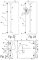
- Figure 22 represents an example of the sixth independent aspect of the invention, mentioned in the introduction, wherein the first furniture part 2 on a first end 45 of two opposite ends 45-46 is provided with at least three male parts 10, and wherein the relation of the distance D1 between a first male part 10 and a second neighboring male part 10 and the distance D2 between this second and a third neighboring male part 10 is at least 1.2.
- Figure 23 represents an example of the fifth independent aspect mentioned in the introduction, wherein the first furniture part 2 on a first of two opposite ends 45-46 is provided with at least a male part 10 as well as with at least a female part 11.
- figure 23 further also forms an example of the sixth independent aspect, wherein the position of the female part 11 is determined by the position of the cooperating therewith male part 10 in the end position 20.
- Figure 24 represents an example of the seventh aspect of the invention, mentioned in the introduction.
- the first furniture part 2 on a first of two opposite ends 45 is provided with at least a first male part 10A
- the first furniture part 2, on a second of these two opposite ends 46 is provided with a second male part 10B, which is least distant from the first male part 10A.
- this always relates to the male parts 10A-10B, which are situated centrally along the respective ends 45-46.
- this first and second male parts 10A-10B are shifted in mutual respect over a distance D3.
- the shifting is at least 5 percent of the length L of the respective end, however, preferably at least 10 percent or more.
- Figure 24 represents that in an attempt to pull the side panels 3-5 away from the top panel according to the arrows 47, a torque effect 48 is created, which pushes the male parts 10-10A-10B more strongly into their end position 20 in the slot 14.
- a torque effect 48 is created, which pushes the male parts 10-10A-10B more strongly into their end position 20 in the slot 14.
- the asymmetric placement thus effects a reinforcement of the whole of the piece of furniture 1.
- the female parts 11 of both side panels 3-5 are made mirrored.
- it can be provided for that such torque effect leads to a simpler de-installation, namely, in that the torque results in the tendency to push the male parts 10-10A-10B loose from their end position 20, however, this is not represented here.
- figure 24 also forms an example of an additional thirteenth aspect, wherein the first furniture part 2 on at least two opposite ends 45-46 has to be coupled to a second furniture part 3, third furniture part 5, respectively, and wherein the movement of the male parts 10-10A-10B along the female parts 11 for the respective two opposite sides 45-46 is opposed to each other.
- the side panel 3 shown on the left hand side must be shifted in the direction of arrow 49
- the side panel 5 shown on the right hand side must be shifted in the opposite direction, namely in the direction of arrow 50, in respect to the top panel 2.
- the eighth independent aspect can be applied broadly.
- embodiments of the eighth aspect are represented, amongst others, in figures 2 to 8 and 11 to 21 .
- the female part 11 is provided in a side 15 of the second furniture part 3, which is provided with a layer-shaped covering 27.
- this respectively relates to furniture parts 2-3 which form an outer side of the piece of furniture 1, and no shelves 7.
- the male part 10 respectively is provided in a narrow side or narrow end 13 of the first furniture part 2, wherein this end 13 is free from layer-shaped coverings 27.
- the slot 14 comprises a bevel 51 or other chamfer, which is beneficial for the quality of the connection.
- first and second furniture parts 2-3 can be formed by any pair of coupled furniture parts.
- a top panel is depicted as the first furniture part 2 and a side panel as the second furniture part 3.
- male parts 10 with circular or approximately circular cross-sections
- these male parts 10 of course also may show other shapes, such as a shape with an oblong cross-section, for example, a wedge shape, analogous to the shape of an insertion wedge in an axis connection.
- the longitudinal direction of the male part 10 in such case preferably is oriented according to the longitudinal direction of the narrow end 13 of the first furniture part 2.
- the male part 10 in all examples is realized as a separate insert, this part can also be made in one piece with the first furniture part 2, for example, in that this male part 10 is formed, by means of machining treatments, on the narrow or distal end 13 of the first furniture part 2.
- connections of the invention which are described as a connection between a first and a second furniture part, can also be applied more broadly than for furniture only. For example, they thus may be applied for any connection, at an angle or flat, in boxes, construction panels, floors and the like.
Landscapes
- Engineering & Computer Science (AREA)
- General Engineering & Computer Science (AREA)
- Mechanical Engineering (AREA)
- Assembled Shelves (AREA)
- Furniture Connections (AREA)
Applications Claiming Priority (4)
| Application Number | Priority Date | Filing Date | Title |
|---|---|---|---|
| BE2014/5044A BE1022567B1 (nl) | 2014-10-31 | 2014-10-31 | Meubel |
| PCT/IB2015/058116 WO2016067162A1 (en) | 2014-10-31 | 2015-10-21 | Furniture |
| EP18196517.9A EP3438474B8 (de) | 2014-10-31 | 2015-10-21 | Möbelstück |
| EP15801933.1A EP3212945B1 (de) | 2014-10-31 | 2015-10-21 | Möbelstück |
Related Parent Applications (3)
| Application Number | Title | Priority Date | Filing Date |
|---|---|---|---|
| EP15801933.1A Division EP3212945B1 (de) | 2014-10-31 | 2015-10-21 | Möbelstück |
| EP18196517.9A Division EP3438474B8 (de) | 2014-10-31 | 2015-10-21 | Möbelstück |
| EP18196517.9A Division-Into EP3438474B8 (de) | 2014-10-31 | 2015-10-21 | Möbelstück |
Publications (2)
| Publication Number | Publication Date |
|---|---|
| EP3640486A1 true EP3640486A1 (de) | 2020-04-22 |
| EP3640486B1 EP3640486B1 (de) | 2023-06-07 |
Family
ID=52814754
Family Applications (3)
| Application Number | Title | Priority Date | Filing Date |
|---|---|---|---|
| EP19212168.9A Active EP3640486B1 (de) | 2014-10-31 | 2015-10-21 | Möbelstück |
| EP18196517.9A Active EP3438474B8 (de) | 2014-10-31 | 2015-10-21 | Möbelstück |
| EP15801933.1A Active EP3212945B1 (de) | 2014-10-31 | 2015-10-21 | Möbelstück |
Family Applications After (2)
| Application Number | Title | Priority Date | Filing Date |
|---|---|---|---|
| EP18196517.9A Active EP3438474B8 (de) | 2014-10-31 | 2015-10-21 | Möbelstück |
| EP15801933.1A Active EP3212945B1 (de) | 2014-10-31 | 2015-10-21 | Möbelstück |
Country Status (5)
| Country | Link |
|---|---|
| US (3) | US10844891B2 (de) |
| EP (3) | EP3640486B1 (de) |
| BE (1) | BE1022567B1 (de) |
| PL (1) | PL3640486T3 (de) |
| WO (1) | WO2016067162A1 (de) |
Families Citing this family (20)
| Publication number | Priority date | Publication date | Assignee | Title |
|---|---|---|---|---|
| US10578140B2 (en) * | 2014-07-08 | 2020-03-03 | James Blake PORTER | Magnetic fasteners and related articles and methods |
| WO2016187533A1 (en) | 2015-05-20 | 2016-11-24 | Richard Stack | Modular cabinet hidden clamping system |
| CN106369019B (zh) | 2015-07-20 | 2020-07-14 | 锁栓公司 | 夹锁紧固件和紧固系统 |
| CN106015232B (zh) * | 2016-07-18 | 2018-01-23 | 广东飞虎网络科技有限公司 | 一种活动卯榫连接轴装置 |
| US11346382B2 (en) | 2017-08-30 | 2022-05-31 | Clark Evan Davis | Modular furniture with stressed dovetail tab joint |
| US11085474B2 (en) * | 2017-09-15 | 2021-08-10 | Clark Davis | Furniture with flexible dovetail dowel and slot joint |
| PL3724518T3 (pl) * | 2017-12-11 | 2024-04-22 | Ikea Supply Ag | Element meblowy i sposób montażu |
| US10506876B1 (en) * | 2018-01-31 | 2019-12-17 | E-Make Co., Ltd. | Self-assembly cabinet |
| EP3781824B1 (de) * | 2018-04-18 | 2024-04-10 | Välinge Innovation AB | Satz aus platten mit mechanischer verriegelungsvorrichtung |
| US11378116B2 (en) | 2018-08-24 | 2022-07-05 | Mcs Industries, Inc. | Furniture assembly |
| US11530716B2 (en) * | 2018-08-24 | 2022-12-20 | Mcs Industries, Inc. | Wall hanging system |
| US10690164B2 (en) | 2018-09-14 | 2020-06-23 | Door County Rustic, LLC | Fasteners, systems, and methods for wood construction |
| US10178908B1 (en) * | 2018-09-19 | 2019-01-15 | Chin Jwu Enterprise Co., Ltd. | Storage rack |
| USD856786S1 (en) * | 2018-10-05 | 2019-08-20 | Door County Rustic LLC | Threaded receiver for tenon |
| IT202000013429A1 (it) | 2020-06-05 | 2021-12-05 | Intelligent Fixings Ltd | Sistema di giunzione tra componenti di un mobile, mobile comprendente detto sistema, un metodo di lavorazione di un componente di un mobile e metodo di realizzazione di detto sistema di giunzione |
| IT202000013438A1 (it) | 2020-06-05 | 2021-12-05 | Intelligent Fixings Ltd | Sistema di giunzione tra componenti di un mobile e mobile comprendente detto sistema |
| CN115867171A (zh) * | 2020-07-17 | 2023-03-28 | 瓦林格创新股份有限公司 | 用于镶板的机械锁定系统 |
| US11767867B2 (en) | 2020-11-17 | 2023-09-26 | Clark Davis | Pivoting joint for wooden furniture |
| BE1029288B1 (nl) * | 2021-04-09 | 2022-11-17 | Decruy Nv | Verbeterd meubelsamenstel, in het bijzonder een lade |
| IT202200001289A1 (it) | 2022-01-26 | 2023-07-26 | Intelligent Fixings Ltd | Sistema di giunzione tra componenti di un mobile, mobile comprendente detto sistema, un metodo di assemblaggio di detto mobile |
Citations (4)
| Publication number | Priority date | Publication date | Assignee | Title |
|---|---|---|---|---|
| CH467421A (de) * | 1968-02-12 | 1969-01-15 | Holz Heinrich | Vorrichtung zum Befestigen von flächenförmigen Bauteilen, insbesondere von Möbelwänden oder -wandteilen, aneinander |
| DE102007058662A1 (de) * | 2007-12-06 | 2009-06-10 | Adam Mathes | Steckverbindungssystem mit einem Steckteil und einem Aufnahmeteil |
| WO2011151758A2 (en) * | 2010-06-03 | 2011-12-08 | Unilin, Bvba | Composed element and corner connection applied herewith |
| WO2013104422A1 (en) | 2012-01-13 | 2013-07-18 | Inter Ikea Systems B.V. | Furniture joint |
Family Cites Families (13)
| Publication number | Priority date | Publication date | Assignee | Title |
|---|---|---|---|---|
| US3600052A (en) * | 1969-09-19 | 1971-08-17 | Jack M Marateck | Knockdown article of furniture and fittings therefor |
| DE2548527C3 (de) * | 1975-10-30 | 1979-09-27 | Fa. Richard Heinze, 4900 Herford | Beschlag zum lösbaren Verbinden zweier senkrecht aufeinanderstoßender Bauteile |
| FR2445461A3 (fr) * | 1978-12-26 | 1980-07-25 | Spinelli Giuseppe | Dispositif de jonction pour assemblage de panneaux employes pour la realisation de meubles |
| DK149498C (da) * | 1983-04-07 | 1986-12-01 | Inter Ikea As | Beklaedning af braedder til f.eks. gulve eller paneler |
| EP0551004A2 (de) * | 1992-01-07 | 1993-07-14 | Kazumi Kamachi | Selbstsicherendes Bolzensystem für die Montage von Möbeln |
| DE9419199U1 (de) * | 1994-11-30 | 1995-01-26 | Chen, Kun-Chen, Ta Chia Chen, Taichung | Werkzeugschrank |
| US6113205A (en) * | 1999-04-13 | 2000-09-05 | Universal Tannery Co., Ltd. | Self-assembled closet |
| BE1018389A3 (nl) | 2008-12-17 | 2010-10-05 | Unilin Bvba | Samengesteld element, meerlagige plaat en paneelvormig element voor het vormen van zulk samengesteld element. |
| CN201743209U (zh) * | 2010-04-21 | 2011-02-16 | 东莞市海崴五金塑胶制品有限公司 | 一种可免使用工具组装的书桌 |
| BE1019361A5 (nl) * | 2010-06-03 | 2012-06-05 | Unilin Bvba | Samengesteld element. |
| BE1020495A4 (nl) * | 2012-02-08 | 2013-11-05 | Unilin Bvba | Samengesteld element en hoekverbinding hierbij toegepast. |
| FR2988275B1 (fr) * | 2012-03-21 | 2014-12-26 | Inovame | Caisson de meuble |
| SE540563C2 (en) * | 2014-11-11 | 2018-10-02 | Ikea Supply Ag | Bent corner furniture connecting piece and a method of making such piece |
-
2014
- 2014-10-31 BE BE2014/5044A patent/BE1022567B1/nl active
-
2015
- 2015-10-21 EP EP19212168.9A patent/EP3640486B1/de active Active
- 2015-10-21 PL PL19212168.9T patent/PL3640486T3/pl unknown
- 2015-10-21 EP EP18196517.9A patent/EP3438474B8/de active Active
- 2015-10-21 EP EP15801933.1A patent/EP3212945B1/de active Active
- 2015-10-21 US US15/522,847 patent/US10844891B2/en active Active
- 2015-10-21 WO PCT/IB2015/058116 patent/WO2016067162A1/en active Application Filing
-
2020
- 2020-10-19 US US17/074,052 patent/US11739779B2/en active Active
-
2023
- 2023-07-11 US US18/350,280 patent/US12071966B2/en active Active
Patent Citations (5)
| Publication number | Priority date | Publication date | Assignee | Title |
|---|---|---|---|---|
| CH467421A (de) * | 1968-02-12 | 1969-01-15 | Holz Heinrich | Vorrichtung zum Befestigen von flächenförmigen Bauteilen, insbesondere von Möbelwänden oder -wandteilen, aneinander |
| DE102007058662A1 (de) * | 2007-12-06 | 2009-06-10 | Adam Mathes | Steckverbindungssystem mit einem Steckteil und einem Aufnahmeteil |
| WO2011151758A2 (en) * | 2010-06-03 | 2011-12-08 | Unilin, Bvba | Composed element and corner connection applied herewith |
| WO2013104422A1 (en) | 2012-01-13 | 2013-07-18 | Inter Ikea Systems B.V. | Furniture joint |
| US20140205373A1 (en) | 2012-01-13 | 2014-07-24 | Inter Ikea Systems B.V. | Furniture joint |
Also Published As
| Publication number | Publication date |
|---|---|
| EP3640486B1 (de) | 2023-06-07 |
| EP3438474B8 (de) | 2020-03-11 |
| US12071966B2 (en) | 2024-08-27 |
| BE1022567B1 (nl) | 2016-06-07 |
| US11739779B2 (en) | 2023-08-29 |
| US10844891B2 (en) | 2020-11-24 |
| EP3212945B1 (de) | 2018-12-12 |
| US20170321734A1 (en) | 2017-11-09 |
| EP3212945A1 (de) | 2017-09-06 |
| EP3438474A1 (de) | 2019-02-06 |
| US20210033128A1 (en) | 2021-02-04 |
| US20230349410A1 (en) | 2023-11-02 |
| EP3438474B1 (de) | 2019-12-04 |
| PL3640486T3 (pl) | 2023-09-11 |
| BE1022567A1 (nl) | 2016-06-07 |
| WO2016067162A1 (en) | 2016-05-06 |
Similar Documents
| Publication | Publication Date | Title |
|---|---|---|
| US12071966B2 (en) | Piece of furniture | |
| US11098484B2 (en) | Panels comprising a mechanical locking device and an assembled product comprising the panels | |
| US10240349B2 (en) | Mechanical locking system for floor panels | |
| CN108496013B (zh) | 用于装配产品的一组镶板 | |
| US9771723B2 (en) | Mechanical locking system for floor panels | |
| US20210214954A1 (en) | Set of floor panels for forming a floor covering | |
| US9650792B2 (en) | Interlocking floor panels and floor system | |
| JP2019508637A5 (de) | ||
| EP4227474A1 (de) | Mechanisches arretierungssystem für bodenplatten | |
| CN108603523A (zh) | 用于提供拆卸凹槽的元件和方法 | |
| KR20140053168A (ko) | 바닥 패널용 기계식 로킹 시스템 | |
| CN107529888B (zh) | 用于家具的组装式抽屉和用于组装该抽屉的方法 | |
| US12065838B2 (en) | Panel and floor covering comprising the same | |
| KR102180904B1 (ko) | 바닥 패널용 기계식 로킹 시스템 | |
| US20140165367A1 (en) | Screw Attachment Plug And Method Of Using The Same |
Legal Events
| Date | Code | Title | Description |
|---|---|---|---|
| PUAI | Public reference made under article 153(3) epc to a published international application that has entered the european phase |
Free format text: ORIGINAL CODE: 0009012 |
|
| STAA | Information on the status of an ep patent application or granted ep patent |
Free format text: STATUS: THE APPLICATION HAS BEEN PUBLISHED |
|
| AC | Divisional application: reference to earlier application |
Ref document number: 3438474 Country of ref document: EP Kind code of ref document: P Ref document number: 3212945 Country of ref document: EP Kind code of ref document: P |
|
| AK | Designated contracting states |
Kind code of ref document: A1 Designated state(s): AL AT BE BG CH CY CZ DE DK EE ES FI FR GB GR HR HU IE IS IT LI LT LU LV MC MK MT NL NO PL PT RO RS SE SI SK SM TR |
|
| STAA | Information on the status of an ep patent application or granted ep patent |
Free format text: STATUS: REQUEST FOR EXAMINATION WAS MADE |
|
| 17P | Request for examination filed |
Effective date: 20200902 |
|
| RBV | Designated contracting states (corrected) |
Designated state(s): AL AT BE BG CH CY CZ DE DK EE ES FI FR GB GR HR HU IE IS IT LI LT LU LV MC MK MT NL NO PL PT RO RS SE SI SK SM TR |
|
| RAP1 | Party data changed (applicant data changed or rights of an application transferred) |
Owner name: UNILIN, BV |
|
| RAP1 | Party data changed (applicant data changed or rights of an application transferred) |
Owner name: FLOORING INDUSTRIES LIMITED, SARL |
|
| STAA | Information on the status of an ep patent application or granted ep patent |
Free format text: STATUS: EXAMINATION IS IN PROGRESS |
|
| 17Q | First examination report despatched |
Effective date: 20210706 |
|
| GRAP | Despatch of communication of intention to grant a patent |
Free format text: ORIGINAL CODE: EPIDOSNIGR1 |
|
| STAA | Information on the status of an ep patent application or granted ep patent |
Free format text: STATUS: GRANT OF PATENT IS INTENDED |
|
| INTG | Intention to grant announced |
Effective date: 20221011 |
|
| RIN1 | Information on inventor provided before grant (corrected) |
Inventor name: SCHACHT, BENNY Inventor name: VAN HOOYDONCK, GUY Inventor name: DEMAN, LUC Inventor name: MAERTENS, LUC |
|
| RAP1 | Party data changed (applicant data changed or rights of an application transferred) |
Owner name: INTER IKEA SYSTEMS B.V. |
|
| GRAS | Grant fee paid |
Free format text: ORIGINAL CODE: EPIDOSNIGR3 |
|
| GRAA | (expected) grant |
Free format text: ORIGINAL CODE: 0009210 |
|
| STAA | Information on the status of an ep patent application or granted ep patent |
Free format text: STATUS: THE PATENT HAS BEEN GRANTED |
|
| AC | Divisional application: reference to earlier application |
Ref document number: 3212945 Country of ref document: EP Kind code of ref document: P Ref document number: 3438474 Country of ref document: EP Kind code of ref document: P |
|
| AK | Designated contracting states |
Kind code of ref document: B1 Designated state(s): AL AT BE BG CH CY CZ DE DK EE ES FI FR GB GR HR HU IE IS IT LI LT LU LV MC MK MT NL NO PL PT RO RS SE SI SK SM TR |
|
| REG | Reference to a national code |
Ref country code: GB Ref legal event code: FG4D |
|
| REG | Reference to a national code |
Ref country code: CH Ref legal event code: EP Ref country code: AT Ref legal event code: REF Ref document number: 1575890 Country of ref document: AT Kind code of ref document: T Effective date: 20230615 |
|
| REG | Reference to a national code |
Ref country code: DE Ref legal event code: R096 Ref document number: 602015084117 Country of ref document: DE |
|
| P01 | Opt-out of the competence of the unified patent court (upc) registered |
Effective date: 20230706 |
|
| REG | Reference to a national code |
Ref country code: LT Ref legal event code: MG9D |
|
| REG | Reference to a national code |
Ref country code: NL Ref legal event code: MP Effective date: 20230607 |
|
| PG25 | Lapsed in a contracting state [announced via postgrant information from national office to epo] |
Ref country code: SE Free format text: LAPSE BECAUSE OF FAILURE TO SUBMIT A TRANSLATION OF THE DESCRIPTION OR TO PAY THE FEE WITHIN THE PRESCRIBED TIME-LIMIT Effective date: 20230607 Ref country code: NO Free format text: LAPSE BECAUSE OF FAILURE TO SUBMIT A TRANSLATION OF THE DESCRIPTION OR TO PAY THE FEE WITHIN THE PRESCRIBED TIME-LIMIT Effective date: 20230907 Ref country code: ES Free format text: LAPSE BECAUSE OF FAILURE TO SUBMIT A TRANSLATION OF THE DESCRIPTION OR TO PAY THE FEE WITHIN THE PRESCRIBED TIME-LIMIT Effective date: 20230607 |
|
| REG | Reference to a national code |
Ref country code: AT Ref legal event code: MK05 Ref document number: 1575890 Country of ref document: AT Kind code of ref document: T Effective date: 20230607 |
|
| PG25 | Lapsed in a contracting state [announced via postgrant information from national office to epo] |
Ref country code: RS Free format text: LAPSE BECAUSE OF FAILURE TO SUBMIT A TRANSLATION OF THE DESCRIPTION OR TO PAY THE FEE WITHIN THE PRESCRIBED TIME-LIMIT Effective date: 20230607 Ref country code: NL Free format text: LAPSE BECAUSE OF FAILURE TO SUBMIT A TRANSLATION OF THE DESCRIPTION OR TO PAY THE FEE WITHIN THE PRESCRIBED TIME-LIMIT Effective date: 20230607 Ref country code: LV Free format text: LAPSE BECAUSE OF FAILURE TO SUBMIT A TRANSLATION OF THE DESCRIPTION OR TO PAY THE FEE WITHIN THE PRESCRIBED TIME-LIMIT Effective date: 20230607 Ref country code: LT Free format text: LAPSE BECAUSE OF FAILURE TO SUBMIT A TRANSLATION OF THE DESCRIPTION OR TO PAY THE FEE WITHIN THE PRESCRIBED TIME-LIMIT Effective date: 20230607 Ref country code: HR Free format text: LAPSE BECAUSE OF FAILURE TO SUBMIT A TRANSLATION OF THE DESCRIPTION OR TO PAY THE FEE WITHIN THE PRESCRIBED TIME-LIMIT Effective date: 20230607 Ref country code: GR Free format text: LAPSE BECAUSE OF FAILURE TO SUBMIT A TRANSLATION OF THE DESCRIPTION OR TO PAY THE FEE WITHIN THE PRESCRIBED TIME-LIMIT Effective date: 20230908 |
|
| PG25 | Lapsed in a contracting state [announced via postgrant information from national office to epo] |
Ref country code: FI Free format text: LAPSE BECAUSE OF FAILURE TO SUBMIT A TRANSLATION OF THE DESCRIPTION OR TO PAY THE FEE WITHIN THE PRESCRIBED TIME-LIMIT Effective date: 20230607 |
|
| PG25 | Lapsed in a contracting state [announced via postgrant information from national office to epo] |
Ref country code: SK Free format text: LAPSE BECAUSE OF FAILURE TO SUBMIT A TRANSLATION OF THE DESCRIPTION OR TO PAY THE FEE WITHIN THE PRESCRIBED TIME-LIMIT Effective date: 20230607 |
|
| PGFP | Annual fee paid to national office [announced via postgrant information from national office to epo] |
Ref country code: GB Payment date: 20231024 Year of fee payment: 9 |
|
| PG25 | Lapsed in a contracting state [announced via postgrant information from national office to epo] |
Ref country code: IS Free format text: LAPSE BECAUSE OF FAILURE TO SUBMIT A TRANSLATION OF THE DESCRIPTION OR TO PAY THE FEE WITHIN THE PRESCRIBED TIME-LIMIT Effective date: 20231007 |
|
| PG25 | Lapsed in a contracting state [announced via postgrant information from national office to epo] |
Ref country code: SM Free format text: LAPSE BECAUSE OF FAILURE TO SUBMIT A TRANSLATION OF THE DESCRIPTION OR TO PAY THE FEE WITHIN THE PRESCRIBED TIME-LIMIT Effective date: 20230607 Ref country code: SK Free format text: LAPSE BECAUSE OF FAILURE TO SUBMIT A TRANSLATION OF THE DESCRIPTION OR TO PAY THE FEE WITHIN THE PRESCRIBED TIME-LIMIT Effective date: 20230607 Ref country code: RO Free format text: LAPSE BECAUSE OF FAILURE TO SUBMIT A TRANSLATION OF THE DESCRIPTION OR TO PAY THE FEE WITHIN THE PRESCRIBED TIME-LIMIT Effective date: 20230607 Ref country code: PT Free format text: LAPSE BECAUSE OF FAILURE TO SUBMIT A TRANSLATION OF THE DESCRIPTION OR TO PAY THE FEE WITHIN THE PRESCRIBED TIME-LIMIT Effective date: 20231009 Ref country code: IS Free format text: LAPSE BECAUSE OF FAILURE TO SUBMIT A TRANSLATION OF THE DESCRIPTION OR TO PAY THE FEE WITHIN THE PRESCRIBED TIME-LIMIT Effective date: 20231007 Ref country code: EE Free format text: LAPSE BECAUSE OF FAILURE TO SUBMIT A TRANSLATION OF THE DESCRIPTION OR TO PAY THE FEE WITHIN THE PRESCRIBED TIME-LIMIT Effective date: 20230607 Ref country code: CZ Free format text: LAPSE BECAUSE OF FAILURE TO SUBMIT A TRANSLATION OF THE DESCRIPTION OR TO PAY THE FEE WITHIN THE PRESCRIBED TIME-LIMIT Effective date: 20230607 Ref country code: AT Free format text: LAPSE BECAUSE OF FAILURE TO SUBMIT A TRANSLATION OF THE DESCRIPTION OR TO PAY THE FEE WITHIN THE PRESCRIBED TIME-LIMIT Effective date: 20230607 |
|
| PGFP | Annual fee paid to national office [announced via postgrant information from national office to epo] |
Ref country code: FR Payment date: 20231026 Year of fee payment: 9 Ref country code: DE Payment date: 20231027 Year of fee payment: 9 |
|
| PGFP | Annual fee paid to national office [announced via postgrant information from national office to epo] |
Ref country code: PL Payment date: 20231011 Year of fee payment: 9 |
|
| REG | Reference to a national code |
Ref country code: DE Ref legal event code: R097 Ref document number: 602015084117 Country of ref document: DE |
|
| PLBE | No opposition filed within time limit |
Free format text: ORIGINAL CODE: 0009261 |
|
| STAA | Information on the status of an ep patent application or granted ep patent |
Free format text: STATUS: NO OPPOSITION FILED WITHIN TIME LIMIT |
|
| PG25 | Lapsed in a contracting state [announced via postgrant information from national office to epo] |
Ref country code: DK Free format text: LAPSE BECAUSE OF FAILURE TO SUBMIT A TRANSLATION OF THE DESCRIPTION OR TO PAY THE FEE WITHIN THE PRESCRIBED TIME-LIMIT Effective date: 20230607 |
|
| PG25 | Lapsed in a contracting state [announced via postgrant information from national office to epo] |
Ref country code: SI Free format text: LAPSE BECAUSE OF FAILURE TO SUBMIT A TRANSLATION OF THE DESCRIPTION OR TO PAY THE FEE WITHIN THE PRESCRIBED TIME-LIMIT Effective date: 20230607 |
|
| 26N | No opposition filed |
Effective date: 20240308 |
|
| PG25 | Lapsed in a contracting state [announced via postgrant information from national office to epo] |
Ref country code: SI Free format text: LAPSE BECAUSE OF FAILURE TO SUBMIT A TRANSLATION OF THE DESCRIPTION OR TO PAY THE FEE WITHIN THE PRESCRIBED TIME-LIMIT Effective date: 20230607 Ref country code: IT Free format text: LAPSE BECAUSE OF FAILURE TO SUBMIT A TRANSLATION OF THE DESCRIPTION OR TO PAY THE FEE WITHIN THE PRESCRIBED TIME-LIMIT Effective date: 20230607 Ref country code: MC Free format text: LAPSE BECAUSE OF FAILURE TO SUBMIT A TRANSLATION OF THE DESCRIPTION OR TO PAY THE FEE WITHIN THE PRESCRIBED TIME-LIMIT Effective date: 20230607 |
|
| REG | Reference to a national code |
Ref country code: CH Ref legal event code: PL |
|
| REG | Reference to a national code |
Ref country code: BE Ref legal event code: MM Effective date: 20231031 |
|
| PG25 | Lapsed in a contracting state [announced via postgrant information from national office to epo] |
Ref country code: LU Free format text: LAPSE BECAUSE OF NON-PAYMENT OF DUE FEES Effective date: 20231021 |
|
| PG25 | Lapsed in a contracting state [announced via postgrant information from national office to epo] |
Ref country code: LU Free format text: LAPSE BECAUSE OF NON-PAYMENT OF DUE FEES Effective date: 20231021 |
|
| PG25 | Lapsed in a contracting state [announced via postgrant information from national office to epo] |
Ref country code: CH Free format text: LAPSE BECAUSE OF NON-PAYMENT OF DUE FEES Effective date: 20231031 |
|
| PG25 | Lapsed in a contracting state [announced via postgrant information from national office to epo] |
Ref country code: CH Free format text: LAPSE BECAUSE OF NON-PAYMENT OF DUE FEES Effective date: 20231031 |
|
| PG25 | Lapsed in a contracting state [announced via postgrant information from national office to epo] |
Ref country code: BE Free format text: LAPSE BECAUSE OF NON-PAYMENT OF DUE FEES Effective date: 20231031 |