EP3640459A1 - Verfahren zum betreiben eines verbrennungsmotors mit einer abgasnachbehandlungseinrichtung - Google Patents
Verfahren zum betreiben eines verbrennungsmotors mit einer abgasnachbehandlungseinrichtung Download PDFInfo
- Publication number
- EP3640459A1 EP3640459A1 EP19198345.1A EP19198345A EP3640459A1 EP 3640459 A1 EP3640459 A1 EP 3640459A1 EP 19198345 A EP19198345 A EP 19198345A EP 3640459 A1 EP3640459 A1 EP 3640459A1
- Authority
- EP
- European Patent Office
- Prior art keywords
- closely
- control system
- reducing agent
- fuel consumption
- bsfc
- Prior art date
- Legal status (The legal status is an assumption and is not a legal conclusion. Google has not performed a legal analysis and makes no representation as to the accuracy of the status listed.)
- Granted
Links
Images

Classifications
-
- B—PERFORMING OPERATIONS; TRANSPORTING
- B60—VEHICLES IN GENERAL
- B60W—CONJOINT CONTROL OF VEHICLE SUB-UNITS OF DIFFERENT TYPE OR DIFFERENT FUNCTION; CONTROL SYSTEMS SPECIALLY ADAPTED FOR HYBRID VEHICLES; ROAD VEHICLE DRIVE CONTROL SYSTEMS FOR PURPOSES NOT RELATED TO THE CONTROL OF A PARTICULAR SUB-UNIT
- B60W10/00—Conjoint control of vehicle sub-units of different type or different function
- B60W10/04—Conjoint control of vehicle sub-units of different type or different function including control of propulsion units
- B60W10/06—Conjoint control of vehicle sub-units of different type or different function including control of propulsion units including control of combustion engines
-
- B—PERFORMING OPERATIONS; TRANSPORTING
- B60—VEHICLES IN GENERAL
- B60W—CONJOINT CONTROL OF VEHICLE SUB-UNITS OF DIFFERENT TYPE OR DIFFERENT FUNCTION; CONTROL SYSTEMS SPECIALLY ADAPTED FOR HYBRID VEHICLES; ROAD VEHICLE DRIVE CONTROL SYSTEMS FOR PURPOSES NOT RELATED TO THE CONTROL OF A PARTICULAR SUB-UNIT
- B60W10/00—Conjoint control of vehicle sub-units of different type or different function
- B60W10/10—Conjoint control of vehicle sub-units of different type or different function including control of change-speed gearings
-
- F—MECHANICAL ENGINEERING; LIGHTING; HEATING; WEAPONS; BLASTING
- F01—MACHINES OR ENGINES IN GENERAL; ENGINE PLANTS IN GENERAL; STEAM ENGINES
- F01N—GAS-FLOW SILENCERS OR EXHAUST APPARATUS FOR MACHINES OR ENGINES IN GENERAL; GAS-FLOW SILENCERS OR EXHAUST APPARATUS FOR INTERNAL-COMBUSTION ENGINES
- F01N3/00—Exhaust or silencing apparatus having means for purifying, rendering innocuous, or otherwise treating exhaust
- F01N3/08—Exhaust or silencing apparatus having means for purifying, rendering innocuous, or otherwise treating exhaust for rendering innocuous
- F01N3/10—Exhaust or silencing apparatus having means for purifying, rendering innocuous, or otherwise treating exhaust for rendering innocuous by thermal or catalytic conversion of noxious components of exhaust
- F01N3/18—Exhaust or silencing apparatus having means for purifying, rendering innocuous, or otherwise treating exhaust for rendering innocuous by thermal or catalytic conversion of noxious components of exhaust characterised by methods of operation; Control
- F01N3/20—Exhaust or silencing apparatus having means for purifying, rendering innocuous, or otherwise treating exhaust for rendering innocuous by thermal or catalytic conversion of noxious components of exhaust characterised by methods of operation; Control specially adapted for catalytic conversion
- F01N3/206—Adding periodically or continuously substances to exhaust gases for promoting purification, e.g. catalytic material in liquid form, NOx reducing agents
- F01N3/208—Control of selective catalytic reduction [SCR], e.g. by adjusting the dosing of reducing agent
-
- F—MECHANICAL ENGINEERING; LIGHTING; HEATING; WEAPONS; BLASTING
- F01—MACHINES OR ENGINES IN GENERAL; ENGINE PLANTS IN GENERAL; STEAM ENGINES
- F01N—GAS-FLOW SILENCERS OR EXHAUST APPARATUS FOR MACHINES OR ENGINES IN GENERAL; GAS-FLOW SILENCERS OR EXHAUST APPARATUS FOR INTERNAL-COMBUSTION ENGINES
- F01N9/00—Electrical control of exhaust gas treating apparatus
-
- F—MECHANICAL ENGINEERING; LIGHTING; HEATING; WEAPONS; BLASTING
- F02—COMBUSTION ENGINES; HOT-GAS OR COMBUSTION-PRODUCT ENGINE PLANTS
- F02D—CONTROLLING COMBUSTION ENGINES
- F02D31/00—Use of speed-sensing governors to control combustion engines, not otherwise provided for
- F02D31/001—Electric control of rotation speed
-
- F—MECHANICAL ENGINEERING; LIGHTING; HEATING; WEAPONS; BLASTING
- F02—COMBUSTION ENGINES; HOT-GAS OR COMBUSTION-PRODUCT ENGINE PLANTS
- F02D—CONTROLLING COMBUSTION ENGINES
- F02D41/00—Electrical control of supply of combustible mixture or its constituents
- F02D41/02—Circuit arrangements for generating control signals
- F02D41/04—Introducing corrections for particular operating conditions
-
- B—PERFORMING OPERATIONS; TRANSPORTING
- B60—VEHICLES IN GENERAL
- B60Y—INDEXING SCHEME RELATING TO ASPECTS CROSS-CUTTING VEHICLE TECHNOLOGY
- B60Y2200/00—Type of vehicle
- B60Y2200/20—Off-Road Vehicles
- B60Y2200/22—Agricultural vehicles
- B60Y2200/221—Tractors
-
- F—MECHANICAL ENGINEERING; LIGHTING; HEATING; WEAPONS; BLASTING
- F01—MACHINES OR ENGINES IN GENERAL; ENGINE PLANTS IN GENERAL; STEAM ENGINES
- F01N—GAS-FLOW SILENCERS OR EXHAUST APPARATUS FOR MACHINES OR ENGINES IN GENERAL; GAS-FLOW SILENCERS OR EXHAUST APPARATUS FOR INTERNAL-COMBUSTION ENGINES
- F01N2430/00—Influencing exhaust purification, e.g. starting of catalytic reaction, filter regeneration, or the like, by controlling engine operating characteristics
-
- F—MECHANICAL ENGINEERING; LIGHTING; HEATING; WEAPONS; BLASTING
- F01—MACHINES OR ENGINES IN GENERAL; ENGINE PLANTS IN GENERAL; STEAM ENGINES
- F01N—GAS-FLOW SILENCERS OR EXHAUST APPARATUS FOR MACHINES OR ENGINES IN GENERAL; GAS-FLOW SILENCERS OR EXHAUST APPARATUS FOR INTERNAL-COMBUSTION ENGINES
- F01N2610/00—Adding substances to exhaust gases
- F01N2610/02—Adding substances to exhaust gases the substance being ammonia or urea
-
- F—MECHANICAL ENGINEERING; LIGHTING; HEATING; WEAPONS; BLASTING
- F01—MACHINES OR ENGINES IN GENERAL; ENGINE PLANTS IN GENERAL; STEAM ENGINES
- F01N—GAS-FLOW SILENCERS OR EXHAUST APPARATUS FOR MACHINES OR ENGINES IN GENERAL; GAS-FLOW SILENCERS OR EXHAUST APPARATUS FOR INTERNAL-COMBUSTION ENGINES
- F01N2900/00—Details of electrical control or of the monitoring of the exhaust gas treating apparatus
- F01N2900/04—Methods of control or diagnosing
- F01N2900/0412—Methods of control or diagnosing using pre-calibrated maps, tables or charts
-
- F—MECHANICAL ENGINEERING; LIGHTING; HEATING; WEAPONS; BLASTING
- F01—MACHINES OR ENGINES IN GENERAL; ENGINE PLANTS IN GENERAL; STEAM ENGINES
- F01N—GAS-FLOW SILENCERS OR EXHAUST APPARATUS FOR MACHINES OR ENGINES IN GENERAL; GAS-FLOW SILENCERS OR EXHAUST APPARATUS FOR INTERNAL-COMBUSTION ENGINES
- F01N2900/00—Details of electrical control or of the monitoring of the exhaust gas treating apparatus
- F01N2900/06—Parameters used for exhaust control or diagnosing
- F01N2900/08—Parameters used for exhaust control or diagnosing said parameters being related to the engine
-
- F—MECHANICAL ENGINEERING; LIGHTING; HEATING; WEAPONS; BLASTING
- F01—MACHINES OR ENGINES IN GENERAL; ENGINE PLANTS IN GENERAL; STEAM ENGINES
- F01N—GAS-FLOW SILENCERS OR EXHAUST APPARATUS FOR MACHINES OR ENGINES IN GENERAL; GAS-FLOW SILENCERS OR EXHAUST APPARATUS FOR INTERNAL-COMBUSTION ENGINES
- F01N2900/00—Details of electrical control or of the monitoring of the exhaust gas treating apparatus
- F01N2900/06—Parameters used for exhaust control or diagnosing
- F01N2900/18—Parameters used for exhaust control or diagnosing said parameters being related to the system for adding a substance into the exhaust
- F01N2900/1806—Properties of reducing agent or dosing system
- F01N2900/1812—Flow rate
-
- F—MECHANICAL ENGINEERING; LIGHTING; HEATING; WEAPONS; BLASTING
- F02—COMBUSTION ENGINES; HOT-GAS OR COMBUSTION-PRODUCT ENGINE PLANTS
- F02D—CONTROLLING COMBUSTION ENGINES
- F02D2200/00—Input parameters for engine control
- F02D2200/02—Input parameters for engine control the parameters being related to the engine
- F02D2200/06—Fuel or fuel supply system parameters
- F02D2200/0625—Fuel consumption, e.g. measured in fuel liters per 100 kms or miles per gallon
-
- F—MECHANICAL ENGINEERING; LIGHTING; HEATING; WEAPONS; BLASTING
- F02—COMBUSTION ENGINES; HOT-GAS OR COMBUSTION-PRODUCT ENGINE PLANTS
- F02D—CONTROLLING COMBUSTION ENGINES
- F02D2250/00—Engine control related to specific problems or objectives
- F02D2250/18—Control of the engine output torque
-
- F—MECHANICAL ENGINEERING; LIGHTING; HEATING; WEAPONS; BLASTING
- F02—COMBUSTION ENGINES; HOT-GAS OR COMBUSTION-PRODUCT ENGINE PLANTS
- F02D—CONTROLLING COMBUSTION ENGINES
- F02D41/00—Electrical control of supply of combustible mixture or its constituents
- F02D41/02—Circuit arrangements for generating control signals
- F02D41/021—Introducing corrections for particular conditions exterior to the engine
- F02D41/0235—Introducing corrections for particular conditions exterior to the engine in relation with the state of the exhaust gas treating apparatus
-
- F—MECHANICAL ENGINEERING; LIGHTING; HEATING; WEAPONS; BLASTING
- F16—ENGINEERING ELEMENTS AND UNITS; GENERAL MEASURES FOR PRODUCING AND MAINTAINING EFFECTIVE FUNCTIONING OF MACHINES OR INSTALLATIONS; THERMAL INSULATION IN GENERAL
- F16H—GEARING
- F16H59/00—Control inputs to control units of change-speed- or reversing-gearings for conveying rotary motion
- F16H59/74—Inputs being a function of engine parameters
-
- Y—GENERAL TAGGING OF NEW TECHNOLOGICAL DEVELOPMENTS; GENERAL TAGGING OF CROSS-SECTIONAL TECHNOLOGIES SPANNING OVER SEVERAL SECTIONS OF THE IPC; TECHNICAL SUBJECTS COVERED BY FORMER USPC CROSS-REFERENCE ART COLLECTIONS [XRACs] AND DIGESTS
- Y02—TECHNOLOGIES OR APPLICATIONS FOR MITIGATION OR ADAPTATION AGAINST CLIMATE CHANGE
- Y02A—TECHNOLOGIES FOR ADAPTATION TO CLIMATE CHANGE
- Y02A50/00—TECHNOLOGIES FOR ADAPTATION TO CLIMATE CHANGE in human health protection, e.g. against extreme weather
- Y02A50/20—Air quality improvement or preservation, e.g. vehicle emission control or emission reduction by using catalytic converters
-
- Y—GENERAL TAGGING OF NEW TECHNOLOGICAL DEVELOPMENTS; GENERAL TAGGING OF CROSS-SECTIONAL TECHNOLOGIES SPANNING OVER SEVERAL SECTIONS OF THE IPC; TECHNICAL SUBJECTS COVERED BY FORMER USPC CROSS-REFERENCE ART COLLECTIONS [XRACs] AND DIGESTS
- Y02—TECHNOLOGIES OR APPLICATIONS FOR MITIGATION OR ADAPTATION AGAINST CLIMATE CHANGE
- Y02T—CLIMATE CHANGE MITIGATION TECHNOLOGIES RELATED TO TRANSPORTATION
- Y02T10/00—Road transport of goods or passengers
- Y02T10/10—Internal combustion engine [ICE] based vehicles
- Y02T10/12—Improving ICE efficiencies
-
- Y—GENERAL TAGGING OF NEW TECHNOLOGICAL DEVELOPMENTS; GENERAL TAGGING OF CROSS-SECTIONAL TECHNOLOGIES SPANNING OVER SEVERAL SECTIONS OF THE IPC; TECHNICAL SUBJECTS COVERED BY FORMER USPC CROSS-REFERENCE ART COLLECTIONS [XRACs] AND DIGESTS
- Y02—TECHNOLOGIES OR APPLICATIONS FOR MITIGATION OR ADAPTATION AGAINST CLIMATE CHANGE
- Y02T—CLIMATE CHANGE MITIGATION TECHNOLOGIES RELATED TO TRANSPORTATION
- Y02T10/00—Road transport of goods or passengers
- Y02T10/10—Internal combustion engine [ICE] based vehicles
- Y02T10/40—Engine management systems
Definitions
- the invention relates to a method for operating an internal combustion engine with an exhaust gas aftertreatment device.
- an exhaust gas aftertreatment device consisting of a soot particle filter and an SCR catalytic converter (SCR - Selective Catalytic Reduction).
- SCR catalytic converter is used for the catalytic reduction of nitrogen oxides contained in the exhaust gas.
- An aqueous urea solution (DEF - Diesel Exhaust Fluid) injected into the exhaust gas stream is used as the reducing agent.
- DEF Diesel Exhaust Fluid
- the internal combustion engine is usually diesel-powered, so that the fuel used is a diesel fuel and the reducing agent is an aqueous urea solution, for example AU32.
- the method according to the invention can be used in particular in the case of mobile vehicle systems from the commercial vehicle sector. These include agricultural, forestry or construction machinery of any type.
- control system can predefine a plurality of fixed reducing agent fuel consumption weights q FD for selection via the operating unit.
- q FD 0 : 1 , 1 : 1 , 1 : 3rd
- a value of 1: 3 also corresponds to a weighting in which there is a price-equivalent consumption of reducing agent and fuel, namely on the common assumption that the reducing agent is approximately three times as expensive as the same amount of fuel.
- control system can initially use a permissible engine speed range n Closely min n Closely Max an engine speed vector n Be determined closely .
- n Narrowly from the available gear ratios r T i derive the gearbox.
- n Closely i n out r T i , where n out represents the current transmission output speed.
- the latter can be detected, for example, by means of a transmission speed sensor.
- the current engine speed n Eng can be determine by means of an engine speed sensor, whereas the instantaneous engine torque M Eng is made available by the engine control unit based on the injection quantity. Alternatively, however, a torque sensor can also be provided for this purpose.
- the target engine speed specified in accordance with the minimum specific reducing agent fuel consumption BSFC Set n Closely set and / or target gear ratio r Set can then from the control system on the internal combustion engine and / or on the gear unit be controlled. This can be done automatically, if necessary also after prior confirmation or approval by the driver via the control unit.
- ⁇ Fuel and ⁇ DEF represent the fuel and reducing agent consumption rates related to the current engine operating point ( n Eng , M Eng ).
- control system has a current engine power reserve P Res C. for the current engine operating point ( n Eng , M Eng ) and one for the target engine operating point n Closely set , M Closely set corresponding target engine power reserve P Res set is calculated, a control of the target engine speed n Closely set and / or target gear ratio r Set only if the target engine power reserve P Res set the current engine power reserve P Res C.
- f T F respectively.
- f T R are stored in the form of corresponding tables in the memory unit assigned to the control system.
- the accuracy in determining the instantaneous transmission output power P out can be further increased if the determined one Minimum specific reducing agent fuel consumption BSFC set is corrected by the control system as a function of a torque component M loss , which is based on a power requirement of auxiliary units driven by the internal combustion engine.
- auxiliary units include electrical generators, hydraulic pumps, fan units, and the like.
- the target engine speed n Closely set and the target gear ratio r set from the control system as a set of points for an interval predetermined for the current gear output power P out P out min , ... , P out Max is calculated and stored in the memory unit as a control curve dependent on the current transmission output power P out .
- the calculation must be carried out by the control system only once and can in particular be carried out at the factory.
- the target engine speed resulting from the control curve depending on the current transmission output power P out n Closely set and / or target gear ratio r Set can then be activated automatically by the control system on the internal combustion engine and / or on the gear unit or, if necessary, after prior confirmation or release by the driver via the control unit.
- the calculation of the target engine speed n Closely set and the target gear ratio r set in the form of the control curve is carried out in a stationary manner by the control system and is transmitted via a data communication device to the storage unit comprised by a mobile vehicle system, for example an agricultural, forestry or construction machine.
- the data communication device can be designed to establish a wireless WLAN connection with a central data and computing server comprised by the control system, the control curve being provided by the central data and computing server and uploaded to the storage unit.
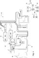
- Fig. 1 shows a mobile vehicle system in the form of a schematically illustrated agricultural tractor with a device for performing the method according to the invention.
- the agricultural tractor 10 has a diesel-powered internal combustion engine 12 and a transmission unit 14 connected downstream of the internal combustion engine 12.
- the transmission unit 14 is a continuously variable transmission or a manual transmission with at least two transmission ratios.
- an exhaust gas aftertreatment device 20 consisting of a soot particle filter 16 and an SCR catalytic converter 18 is also present.
- the SCR catalytic converter 18 serves for the catalytic reduction of nitrogen oxides contained in the exhaust gas.
- An aqueous urea solution, for example EU 32, injected into the exhaust gas stream is used as the reducing agent.
- the device 22 provided in the agricultural tractor 10 comprises an electronic control system 24, a memory unit 26 assigned to it and an operating unit 28 designed as a touch-sensitive display surface.
- a data communication device 30 enables a wireless WLAN connection 32 to be established with a central data and computing server 34.
- control system 24 is connected via a CAN data bus 36 to an engine control unit 38 and a transmission control 40 of the agricultural tractor 10, so that the control system 24 is able to adjust the engine speed and transmission ratio independently of the driver.
- a transmission speed sensor 42 or engine speed sensor 44 is used to detect a current transmission output speed n out or a current engine speed n Eng .
- the speed signals generated by the sensors 42, 46 are fed to the control system 24 for evaluation.
- Fig. 2 shows an embodiment of the inventive method performed by the device 22 in the form of a simplified flow chart.
- the method is initialized in a starting step 100 when the agricultural tractor 10 is started up. Subsequently, in a first step 102, the driver is asked via the display surface encompassed by the operating unit 28 to specify a reducing agent fuel consumption weight q FD to be observed during the operation of the internal combustion engine 12. The specification made by the driver via the control unit 28 is then communicated to the control system 24.
- a value of 1: 3 also corresponds to a weighting in which there is a price-equivalent consumption of reducing agent and fuel, namely on the common assumption that the reducing agent is approximately three times as expensive as the same amount of fuel.
- control system 24 first of all uses a permissible engine speed range in the second step 104 n Closely min , n Closely Max an engine speed vector n Narrowly determined.
- the engine speed vector becomes n Narrowly from the available gear ratios r T i derived from the manual transmission.
- the current engine speed n Eng is determined by means of the engine speed sensor 44, whereas the current engine torque M Eng is made available by the engine control unit 38 based on the injection quantity.
- a (in Fig. 1 torque sensor (not shown) may be provided.
- the determined vector field is checked by the control system 24 in second step 104 with respect to such engine operating points n Closely i M Closely i , that lie outside the torque potential of the internal combustion engine 12, adjusted.
- the control system 24 uses this in a second step 104 for each of the engine operating points lying within the cleaned vector field n Closely i M Closely i an associated specific reducing agent fuel consumption BSFC i . Subsequently, in a third step 106 following the second step 104, the control system 24 uses that element i Set as the target engine operating point n Closely set M Closely set selected, which corresponds to a minimum specific reducing agent fuel consumption BSFC Set , with the control system 24 in accordance with the selected element i Set a target engine speed n Closely set and from this a target gear ratio r Set is specified taking into account a current transmission output speed n out .
- the target engine speed specified in accordance with the minimum specific reducing agent fuel consumption BSFC Set n Closely set and / or target gear ratio r Set is then controlled by the control system 24 in a fourth step 108 following the third step 106 on the internal combustion engine 12 and / or on the gear unit 14. This is done automatically if necessary also after prior confirmation or release by the driver via the control unit 28.
- f T F the functions f T F respectively.
- f T R stored in the form of corresponding tables in the memory unit 26 assigned to the control system 24.
- the accuracy in the determination of the current transmission output power P out can be further increased by the determined minimum specific reducing agent fuel consumption BSFC Set by the control system 24 as a function of a torque component M loss , which is based on a power requirement of auxiliary units driven by the internal combustion engine 12 is corrected.
- auxiliary units include including electrical generators, hydraulic pumps, fan units, and the like.
- control system 24 determines a current specific reducing agent fuel consumption BSFC c in the third step 106.
- the control system 24 provides a current engine power reserve P Res C. for the current engine operating point ( n Eng , M Eng ) and one for the target engine operating point n Closely set M Closely set Corresponding target engine power reserve PRes is calculated, with the target engine speed being controlled n Closely set and / or target gear ratio r Set only if the target engine power reserve P Res set the current engine power reserve P Res C.
- the method is then ended in a final step 110.
- the target engine speed is reduced in a second step 104 in order to reduce the computing effort n Closely set and the target gear ratio r Set from the control system 24 starting from equation (1) as a set of points for an interval predetermined for the current gear output power P out P out min , ... , P out Max calculated and stored in the memory unit 26 as a control curve dependent on the current transmission output power P out .
- the calculation must be carried out by the control system only once and can in particular be carried out at the factory.
- the calculation of the target engine speed is optional n Closely set and the target gear ratio r set in the form of the control curve carried out by a stationary computing unit - here in the form of the central data and computing server 26 which is functionally included in the control system 24 - outside the agricultural tractor 10 and via the data communication device 30 to the agricultural tractor 10 Storage unit 26 transmitted.
- the control curve will uploaded by the central data and computing server 34 to the storage unit 26 via the WLAN connection 32.
- the target engine speed resulting from the control curve depending on the current transmission output power P out n Closely set and / or target gear ratio r Set here in the fourth step 108 by the control system on the internal combustion engine and / or on the gear unit automatically or optionally after prior confirmation or release by the driver via the control unit.
Landscapes
- Engineering & Computer Science (AREA)
- Chemical & Material Sciences (AREA)
- Combustion & Propulsion (AREA)
- Mechanical Engineering (AREA)
- General Engineering & Computer Science (AREA)
- Chemical Kinetics & Catalysis (AREA)
- Transportation (AREA)
- Health & Medical Sciences (AREA)
- Toxicology (AREA)
- Control Of Vehicle Engines Or Engines For Specific Uses (AREA)
- Control Of Transmission Device (AREA)
- Combined Controls Of Internal Combustion Engines (AREA)
Abstract
Description
- Die Erfindung bezieht sich auf ein Verfahren zum Betreiben eines Verbrennungsmotors mit einer Abgasnachbehandlungseinrichtung.
- Um den Schadstoffausstoß dieselbetriebener Verbrennungsmotoren zu verringern, weisen moderne Landmaschinen im Allgemeinen eine aus einem Rußpartikelfilter sowie einem SCR-Katalysator (SCR - Selective Catalytic Reduction) bestehende Abgasnachbehandlungseinrichtung auf. Der SCR-Katalysator dient hierbei der katalytischen Reduktion von im Abgas enthaltenen Stickoxiden. Als Reduktionsmittel wird eine in den Abgasstrom eingespritzte wässrige Harnstofflösung (DEF - Diesel Exhaust Fluid) verwendet. Das Verbrauchsverhältnis zwischen Dieselkraftstoff und Harnstofflösung hängt letztlich vom Betriebspunkt des Verbrennungsmotors ab und ist für den Fahrer hinsichtlich der verursachten Verbrauchskosten nicht ohne Weiteres einschätzbar.
- Es ist daher Aufgabe der vorliegenden Erfindung, ein Verfahren der eingangs genannten Art dahingehend anzugeben, dass ein kostenoptimierter Betrieb des Verbrennungsmotors unterstützt wird.
- Diese Aufgabe wird durch ein Verfahren mit den Merkmalen des Patentanspruchs 1 gelöst.
- Das erfindungsgemäße Verfahren zum Betreiben eines Verbrennungsmotors mit einer Abgasnachbehandlungseinrichtung sieht vor, dass
- (a) in einem ersten Schritt einem Kontrollsystem eine beim Betrieb des Verbrennungsmotors einzuhaltende Reduktionsmittel-Kraftstoff-Verbrauchsgewichtung qFD mitgeteilt wird, wobei die Reduktionsmittel-Kraftstoff-Verbrauchsgewichtung qFD über eine mit dem Kontrollsystem kommunizierende Bedieneinheit vorgegeben wird,
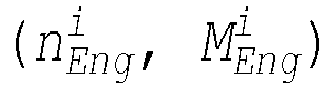
- (b) in einem zweiten Schritt von dem Kontrollsystem ausgehend von der vorgegebenen Reduktionsmittel-Kraftstoff-Verbrauchsgewichtung qFD ein Vektorfeld korrespondierender Motorbetriebspunkte



- (c) in einem dritten Schritt von dem Kontrollsystem aus dem ermittelten Vektorfeld dasjenige Element iSet als Zielmotorbetriebspunkt


- Auf diese Weise ist es möglich, die Motordrehzahl sowie die Getriebeübersetzung unter Berücksichtigung der aktuellen Kraftstoff- bzw. Reduktionsmittelpreise im Sinne eines kostenoptimierten Verbrauchsverhältnisses anzupassen.
- Der Verbrennungsmotor ist üblicherweise dieselbetrieben, sodass es sich bei dem verwendeten Kraftstoff um einen Dieselkraftstoff und bei dem Reduktionsmittel um eine wässrige Harnstofflösung, beispielsweise AU32, handelt.
- Das erfindungsgemäße Verfahren kann insbesondere bei mobilen Fahrzeugsystemen aus dem Nutzfahrzeugbereich Verwendung finden. Hierzu gehören unter anderem Land-, Forst- oder Baumaschinen beliebiger Bauart.
- Vorteilhafte Ausgestaltungen des erfindungsgemäßen Verfahrens gehen aus den Unteransprüchen hervor.
- Vorzugsweise ist die Reduktionsmittel-Kraftstoff-Verbrauchsgewichtung qFD definiert als Verhältnis der Verbrauchsraten ṁDEF und ṁFuel von Reduktionsmittel und Kraftstoff,

- Hierbei können von dem Kontrollsystem mehrere feste Reduktionsmittel-Kraftstoff-Verbrauchsgewichtungen qFD zur Auswahl über die Bedieneinheit vorgegeben werden. Insbesondere kann eine Auswahl zwischen drei verschiedenen Werten vorgesehen sein:

- Bei einer Gewichtung von 0:1 findet zur Ableitung des spezifischen Reduktionsmittel-Kraftstoff-Verbrauchs BSFCi ausschließlich ein Verbrauch von Kraftstoff, nicht jedoch von Reduktionsmittel Berücksichtigung, wohingegen im Falle einer Gewichtung von 1:1 ein Verbrauch von Reduktionsmittel und Kraftstoff zu gleichen Teilen angesetzt wird. Ein Wert von 1:3 entspricht ferner einer Gewichtung, bei der ein preislich äquivalenter Verbrauch von Reduktionsmittel und Kraftstoff vorliegt, nämlich unter der gängigen Annahme, dass das Reduktionsmittel ungefähr dreimal so teuer ist wie die gleiche Menge Kraftstoff. Durch Vorgabe einer überschaubaren Anzahl fester Werte für die Reduktionsmittel-Kraftstoff-Verbrauchsgewichtung qFD wird die Auswahl für den Fahrer wesentlich vereinfacht. Alternativ ist bei entsprechend erfahrenen Fahrern jedoch auch eine freie Vorgabe vorstellbar.
- Zur Ermittlung des Vektorfelds kann von dem Kontrollsystem zunächst für einen zulässigen Motordrehzahlbereich

n Eng bestimmt werden. - Handelt es sich bei der Getriebeeinheit um ein stufenloses Getriebe, kann dies unter Annahme von N möglichen Werten für die Motordrehzahl erfolgen,

- Dies trägt dem Umstand Rechnung, dass die Beeinflussung der Motordrehzahl seitens eines Motorsteuergeräts im Allgemeinen nicht kontinuierlich, sondern in diskreten Drehzahlschritten erfolgt. Die Anzahl N bzw. Breite Δn der Drehzahlschritte wird dabei letztlich durch die Rechenkapazität des verwendeten Motorsteuergeräts nach oben bzw. unten hin begrenzt.
- Ist hingegen ein Schaltgetriebe mit wenigstens zwei Getriebeübersetzungen vorgesehen, so bietet es sich an, den Motordrehzahlvektor
n Eng aus den zur Verfügung stehenden Getriebeübersetzungen

- Ausgehend von einem vereinfachten Ansatz kann die momentane Getriebeausgangsleistung Pout unmittelbar aus einer von dem Verbrennungsmotor bereitgestellten momentanen Motorausgangsleistung PEng abgeleitet werden,

- Die momentane Motorausgangsleistung PEng ergibt sich hierbei zu

- Damit ergibt sich für den mit dem Motordrehzahlvektor
n Eng korrespondierenden MotordrehmomentvektorM Eng in Komponentenschreibweise
- Andererseits sind die Verbrauchsraten ṁDEF und ṁFuel von Reduktionsmittel und Kraftstoff in jedem der möglichen Motorbetriebspunkte (nEng, MEng ) des Verbrennungsmotors bekannt,


- Diese sind in Gestalt entsprechender Tabellen in einer dem Kontrollsystem zugeordneten Speichereinheit hinterlegt und erlauben umgekehrt die Ableitung des im i-ten Motorbetriebspunkt

- Die entsprechend dem minimalen spezifischen Reduktionsmittel-Kraftstoff-Verbrauch BSFCSet vorgegebene Zielmotordrehzahl

- Um einen von Antriebskrafteinbrüchen freien Betrieb des Verbrennungsmotors sicherzustellen, besteht die Möglichkeit, dass das Vektorfeld von dem Kontrollsystem bezüglich solcher Motorbetriebspunkte

- Des Weiteren ist es möglich, dass von dem Kontrollsystem ein aktueller spezifischer Reduktionsmittel-Kraftstoff-Verbrauch BSFCc ermittelt wird, wobei eine Einsteuerung der Zielmotordrehzahl


- wobei ṁFuel und ṁDEF die auf den momentanen Motorbetriebspunkt (nEng, MEng ) bezogenen Verbrauchsraten von Kraftstoff und Reduktionsmittel darstellen.
- Durch entsprechende Vorgabe der Verbrauchsdifferenz ΔBSFC lassen sich überflüssige korrigierende Eingriffe in die Motordrehzahl bzw. die Getriebeübersetzung aufgrund lediglich geringfügiger Variationen des aktuellen spezifischen Reduktionsmittel-Kraftstoff-Verbrauchs BSFCc vermeiden. Das Verbrauchs-bzw. Betriebsverhalten des Verbrennungsmotors bzw. der Getriebeeinheit wird so maßgeblich verbessert.
- In diesem Zusammenhang kann auch vorgesehen sein, dass von dem Kontrollsystem eine aktuelle Motorleistungsreserve





- Somit erfolgt ein korrigierender Eingriff in die Motordrehzahl bzw. die Getriebeübersetzung seitens des Kontrollsystems nur dann, wenn dieser hinsichtlich der erzielbaren Leistungsausbeute zu einem merklichen Nutzen führt.
- Des Weiteren können zur genauen Bestimmung der momentanen Getriebeausgangsleistung Pout innerhalb der Getriebeeinheit auftretende Leistungsverluste berücksichtigt werden, indem der ermittelte minimale spezifische Reduktionsmittel-Kraftstoff-Verbrauch BSFCSet von dem Kontrollsystem in Abhängigkeit eines für die Getriebeeinheit ermittelten Wirkungsgrads


- Die Funktionen


- Die Genauigkeit bei der Bestimmung der momentanen Getriebeausgangsleistung Pout lässt sich weiter erhöhen, wenn der ermittelte minimale spezifische Reduktionsmittel-Kraftstoff-Verbrauch BSFCSet von dem Kontrollsystem in Abhängigkeit eines Drehmomentanteils Mloss, der auf einen Leistungsbedarf von mittels des Verbrennungsmotors angetriebenen Nebenaggregaten zurückgeht, korrigiert wird. Zu diesen Nebenaggregaten gehören unter anderem elektrische Generatoren, Hydraulikpumpen, Lüfteraggregate, und dergleichen. Der entsprechende Drehmomentanteil ist hierbei in erster Näherung eine Funktion der momentanen Motordrehzahl nEng,

- Dementsprechend kann der vereinfachte Ansatz Pout = PEng ersetzt werden durch

- Daraus wiederum ergibt sich der entsprechend korrigierte Motordrehmomentvektor
M Eng in Komponentenschreibweise zu
- Zur Verringerung des Rechenaufwands kann vorgesehen sein, dass die Zielmotordrehzahl


- Die sich je nach momentaner Getriebeausgangsleistung Pout aus der Steuerkurve ergebende Zielmotordrehzahl

- Denkbar ist es auch, dass die Berechnung der Zielmotordrehzahl

- Das erfindungsgemäße Verfahren wird im Folgenden anhand der beigefügten Zeichnungen näher erläutert. Es zeigen:
- Fig. 1
- ein mobiles Fahrzeugsystem in Gestalt eines landwirtschaftlichen Traktors mit einer Vorrichtung zur Durchführung des erfindungsgemäßen Verfahrens, und
- Fig. 2
- ein Ausführungsbeispiel des erfindungsgemäßen Verfahrens in Gestalt eines vereinfacht dargestellten Flussdiagramms.
-
Fig. 1 zeigt ein mobiles Fahrzeugsystem in Gestalt eines schematisch dargestellten landwirtschaftlichen Traktors mit einer Vorrichtung zur Durchführung des erfindungsgemäßen Verfahrens. - Der landwirtschaftliche Traktor 10 weist einen dieselbetriebenen Verbrennungsmotor 12 sowie eine dem Verbrennungsmotor 12 nachgeschaltete Getriebeeinheit 14 auf. Bei der Getriebeeinheit 14 handelt es sich um ein stufenloses Getriebe bzw. ein Schaltgetriebe mit mindestens zwei Getriebeübersetzungen. Um den Schadstoffausstoß des Verbrennungsmotors 12 zu verringern, ist ferner eine aus einem Rußpartikelfilter 16 sowie einem SCR-Katalysator 18 bestehende Abgasnachbehandlungseinrichtung 20 vorhanden. Der SCR-Katalysator 18 dient hierbei der katalytischen Reduktion von im Abgas enthaltenen Stickoxiden. Als Reduktionsmittel wird eine in den Abgasstrom eingespritzte wässrige Harnstofflösung, beispielsweise EU 32, verwendet.
- Die in dem landwirtschaftlichen Traktor 10 vorgesehene Vorrichtung 22 umfasst ein elektronisches Kontrollsystem 24, eine dieser zugeordnete Speichereinheit 26 sowie eine als berührungsempfindliche Anzeigeoberfläche ausgebildete Bedieneinheit 28. Eine Datenkommunikationseinrichtung 30 ermöglicht die Herstellung einer drahtlosen WLAN-Verbindung 32 mit einem zentralen Daten- und Rechenserver 34.
- Des Weiteren steht das Kontrollsystem 24 über einen CAN-Datenbus 36 mit einem Motorsteuergerät 38 sowie einer Getriebesteuerung 40 des landwirtschaftlichen Traktors 10 in Verbindung, sodass es dem Kontrollsystem 24 möglich ist, eine fahrerunabhängige Anpassung von Motordrehzahl und Getriebeübersetzung vorzunehmen.
- Ein Getriebedrehzahlsensor 42 bzw. Motordrehzahlsensor 44 dient der Erfassung einer momentanen Getriebeausgangsdrehzahl nout bzw. einer momentanen Motordrehzahl nEng. Die von den Sensoren 42, 46 jeweils erzeugten Drehzahlsignale werden dem Kontrollsystem 24 zur Auswertung zugeführt.
-
Fig. 2 zeigt ein Ausführungsbeispiel des von der Vorrichtung 22 durchgeführten erfindungsgemäßen Verfahrens in Gestalt eines vereinfacht dargestellten Flussdiagramms. - Das Verfahren wird bei Inbetriebnahme des landwirtschaftlichen Traktors 10 in einem Startschritt 100 initialisiert. Anschließend wird in einem ersten Schritt 102 der Fahrer über die von der Bedieneinheit 28 umfasste Anzeigeoberfläche aufgefordert, eine beim Betrieb des Verbrennungsmotors 12 einzuhaltende Reduktionsmittel-Kraftstoff-Verbrauchsgewichtung qFD vorzugeben. Die vom Fahrer über die Bedieneinheit 28 vorgenommene Vorgabe wird dem Kontrollsystem 24 anschließend mitgeteilt.
- Die Reduktionsmittel-Kraftstoff-Verbrauchsgewichtung qFD ist definiert als Verhältnis der Verbrauchsraten ṁDEF und ṁFuel von Reduktionsmittel und Kraftstoff,

- Im vorliegenden Fall werden von dem Kontrollsystem 24 im ersten Schritt 102 mehrere feste Reduktionsmittel-Kraftstoff-Verbrauchsgewichtungen qFD zur Auswahl über die Bedieneinheit 28 vorgegeben. Es ist eine Auswahl zwischen drei verschiedenen Werten vorgesehen:

- Bei einer Gewichtung von 0:1 findet im Folgenden ausschließlich ein Verbrauch von Kraftstoff, nicht jedoch von Reduktionsmittel Berücksichtigung, wohingegen im Falle einer Gewichtung von 1:1 ein Verbrauch von Reduktionsmittel und Kraftstoff zu gleichen Teilen angesetzt wird. Ein Wert von 1:3 entspricht ferner einer Gewichtung, bei der ein preislich äquivalenter Verbrauch von Reduktionsmittel und Kraftstoff vorliegt, nämlich unter der gängigen Annahme, dass das Reduktionsmittel ungefähr dreimal so teuer ist wie die gleiche Menge Kraftstoff. Durch Vorgabe einer überschaubaren Anzahl fester Werte für die Reduktionsmittel-Kraftstoff-Verbrauchsgewichtung qFD wird die Auswahl für den Fahrer wesentlich vereinfacht. Alternativ ist bei entsprechend erfahrenen Fahrern eine freie Vorgabe über die Bedieneinheit 28 vorgesehen.
- In einem auf den ersten Schritt 102 folgenden zweiten Schritt 104 wird von dem Kontrollsystem 24 ausgehend von der vorgegebenen Reduktionsmittel-Kraftstoff-Verbrauchsgewichtung qFD ein Vektorfeld korrespondierender Motorbetriebspunkte


- Hierbei gibt


- Zur Ermittlung des Vektorfelds wird von dem Kontrollsystem 24 im zweiten Schritt 104 zunächst für einen zulässigen Motordrehzahlbereich

n Eng bestimmt. - Handelt es sich bei der Getriebeeinheit 14 um ein stufenloses Getriebe, erfolgt dies unter Annahme von N möglichen Werten für die Motordrehzahl,

- Dies trägt dem Umstand Rechnung, dass die Beeinflussung der Motordrehzahl seitens des Motorsteuergeräts 38 im Allgemeinen nicht kontinuierlich, sondern in diskreten Drehzahlschritten erfolgt. Die Anzahl N bzw. Breite Δn der Drehzahlschritte wird dabei letztlich durch die Rechenkapazität des verwendeten Motorsteuergeräts 38 nach oben bzw. unten hin begrenzt.
- Ist hingegen ein Schaltgetriebe mit wenigstens zwei Getriebeübersetzungen vorgesehen, so wird der Motordrehzahlvektor
n Eng aus den zur Verfügung stehenden Getriebeübersetzungen

- Für die Ableitung der momentanen Getriebeausgangsleistung Pout sind nun zwei unterschiedliche Vorgehensweisen vorgesehen. Ausgehend von einem vereinfachten Ansatz wird die momentane Getriebeausgangsleistung Pout im zweiten Schritt 104 unmittelbar aus einer von dem Verbrennungsmotor 12 bereitgestellten momentanen Motorausgangsleistung PEng abgeleitet,

- Die momentane Motorausgangsleistung PEng ergibt sich hierbei zu

Fig. 1 nicht abgebildeter) Drehmomentsensor vorgesehen sein. - Damit ergibt sich für den mit dem Motordrehzahlvektor
n Eng korrespondierenden MotordrehmomentvektorM Eng in Komponentenschreibweise
- Um einen von Antriebskrafteinbrüchen freien Betrieb des Verbrennungsmotors 12 sicherzustellen, wird das ermittelte Vektorfeld von dem Kontrollsystem 24 im zweiten Schritt 104 bezüglich solcher Motorbetriebspunkte

- Ferner sind die Verbrauchsraten ṁDEF und ṁFuel von Reduktionsmittel und Kraftstoff in jedem der möglichen Motorbetriebspunkte (nEng, MEng ) des Verbrennungsmotors 12 bekannt,


- Diese sind in Gestalt entsprechender Tabellen in der dem Kontrollsystem 24 zugeordneten Speichereinheit 26 hinterlegt. Das Kontrollsystem 24 leitet daraus im zweiten Schritt 104 für jeden der innerhalb des bereinigten Vektorfelds liegenden Motorbetriebspunkte


- Die entsprechend dem minimalen spezifischen Reduktionsmittel-Kraftstoff-Verbrauch BSFCSet vorgegebene Zielmotordrehzahl

- Optional wird anstelle der vereinfachenden Annahme POut = PEng ein umfassenderer Ansatz verfolgt, bei dem zur genauen Bestimmung der momentanen Getriebeausgangsleistung Pout innerhalb der Getriebeeinheit 14 auftretende Leistungsverluste berücksichtigt werden. Hierzu wird der ermittelte minimale spezifische Reduktionsmittel-Kraftstoff-Verbrauch BSFCSet von dem Kontrollsystem 24 in Abhängigkeit eines für die Getriebeeinheit 14 ermittelten Wirkungsgrads


- Hierbei sind die Funktionen


- Die Genauigkeit bei der Bestimmung der momentanen Getriebeausgangsleistung Pout lässt sich weiter erhöhen, indem der ermittelte minimale spezifische Reduktionsmittel-Kraftstoff-Verbrauch BSFCSet von dem Kontrollsystem 24 in Abhängigkeit eines Drehmomentanteils Mloss, der auf einen Leistungsbedarf von mittels des Verbrennungsmotors 12 angetriebenen Nebenaggregaten zurückgeht, korrigiert wird. Zu diesen Nebenaggregaten gehören unter anderem elektrische Generatoren, Hydraulikpumpen, Lüfteraggregate, und dergleichen. Der entsprechende Drehmomentanteil ist hierbei in erster Näherung eine Funktion der momentanen Motordrehzahl nEng,

- Dementsprechend wird der vereinfachte Ansatz Pout = PEng ersetzt durch

- Daraus wiederum ergibt sich der entsprechend korrigierte Motordrehmomentvektor
M ENG in Komponentenschreibweise zu
- Des Weiteren wird von dem Kontrollsystem 24 im dritten Schritt 106 ein aktueller spezifischer Reduktionsmittel-Kraftstoff-Verbrauch BSFCc ermittelt. Eine Einsteuerung der Zielmotordrehzahl


- Durch entsprechende Vorgabe der Verbrauchsdifferenz ΔBSFC lassen sich überflüssige korrigierende Eingriffe in die Motordrehzahl bzw. die Getriebeübersetzung aufgrund lediglich geringfügiger Variationen des aktuellen spezifischen Reduktionsmittel-Kraftstoff-Verbrauchs BSFCc vermeiden. Das Verbrauchs- bzw. Betriebsverhalten des Verbrennungsmotors 12 bzw. der Getriebeeinheit 14 wird so maßgeblich verbessert.
- Zusätzlich ist im dritten Schritt 106 vorgesehen, dass von dem Kontrollsystem 24 eine aktuelle Motorleistungsreserve







- Somit erfolgt ein korrigierender Eingriff in die Motordrehzahl bzw. die Getriebeübersetzung seitens das Kontrollsystems 24 nur dann, wenn dieser hinsichtlich der erzielbaren Leistungsausbeute zu einem merklichen Nutzen führt.
- Anschließend wird das Verfahren in einem Schlussschritt 110 beendet.
- Gemäß einer Abwandlung des erfindungsgemäßen Verfahrens wird zur Verringerung des Rechenaufwands im zweiten Schritt 104 die Zielmotordrehzahl


- Optional wird die Berechnung der Zielmotordrehzahl

- Der übrige Verfahrensablauf bleibt unverändert, sodass insoweit auf die zugehörige Beschreibung verwiesen sei. Insbesondere wird die sich je nach momentaner Getriebeausgangsleistung Pout aus der Steuerkurve ergebende Zielmotordrehzahl

Claims (11)
- Verfahren zum Betreiben eines Verbrennungsmotors mit einer Abgasnachbehandlungseinrichtung, bei dem(a) in einem ersten Schritt einem Kontrollsystem (24) eine beim Betrieb des Verbrennungsmotors (12) einzuhaltende Reduktionsmittel-Kraftstoff-Verbrauchsgewichtung qFD mitgeteilt wird, wobei die Reduktionsmittel-Kraftstoff-Verbrauchsgewichtung qFD über eine mit dem Kontrollsystem (24) kommunizierende Bedieneinheit (28) vorgegeben wird,(b) in einem zweiten Schritt von dem Kontrollsystem (24) ausgehend von der vorgegebenen Reduktionsmittel-Kraftstoff-Verbrauchsgewichtung qFD ein Vektorfeld korrespondierender Motorbetriebspunkte


 (c) in einem dritten Schritt von dem Kontrollsystem (24) aus dem ermittelten Vektorfeld dasjenige Element iSet als Zielmotorbetriebspunkt

- Verfahren nach Anspruch 1, dadurch gekennzeichnet, dass von dem Kontrollsystem (24) mehrere feste Reduktionsmittel-Kraftstoff-Verbrauchsgewichtungen qFD zur Auswahl über die Bedieneinheit (28) vorgegeben werden.
- Verfahren nach Anspruch 1 oder 2, dadurch gekennzeichnet, dass die entsprechend dem minimalen spezifischen Reduktionsmittel-Kraftstoff-Verbrauch BSFCSet vorgegebene Zielmotordrehzahl

- Verfahren nach wenigstens einem der Ansprüche 1 bis 3, dadurch gekennzeichnet, dass das Vektorfeld von dem Kontrollsystem (24) bezüglich solcher Motorbetriebspunkte

- Verfahren nach wenigstens einem der Ansprüche 1 bis 4, dadurch gekennzeichnet, dass von dem Kontrollsystem (24) ein aktueller spezifischer Reduktionsmittel-Kraftstoff-Verbrauch BSFCc ermittelt wird, wobei eine Einsteuerung der Zielmotordrehzahl

- Verfahren nach wenigstens einem der Ansprüche 1 bis 5, dadurch gekennzeichnet, dass von dem Kontrollsystem (24) eine aktuelle Motorleistungsreserve


- Verfahren nach wenigstens einem der Ansprüche 1 bis 6, dadurch gekennzeichnet, dass der ermittelte minimale spezifische Reduktionsmittel-Kraftstoff-Verbrauch BSFCSet von dem Kontrollsystem (24) in Abhängigkeit eines für die Getriebeeinheit (14) ermittelten Wirkungsgrads


- Verfahren nach wenigstens einem der Ansprüche 1 bis 7, dadurch gekennzeichnet, dass der ermittelte minimale spezifische Reduktionsmittel-Kraftstoff-Verbrauch BSFCSet von dem Kontrollsystem (24) in Abhängigkeit eines Drehmomentanteils Mloss, der auf einen Leistungsbedarf von mittels des Verbrennungsmotors (12) angetriebenen Nebenaggregaten zurückgeht, korrigiert wird.
- Verfahren nach Anspruch 1, dadurch gekennzeichnet, dass die Zielmotordrehzahl


- Verfahren nach Anspruch 9, dadurch gekennzeichnet, dass die sich je nach momentaner Getriebeausgangsleistung Pout aus der Steuerkurve ergebende Zielmotordrehzahl

- Verfahren nach Anspruch 9 oder 10, dadurch gekennzeichnet, dass die Berechnung der Zielmotordrehzahl

Applications Claiming Priority (1)
| Application Number | Priority Date | Filing Date | Title |
|---|---|---|---|
| DE102018216366.9A DE102018216366A1 (de) | 2018-09-25 | 2018-09-25 | Verfahren zum Betreiben eines Verbrennungsmotors mit einer Abgasnachbehandlungseinrichtung |
Publications (2)
| Publication Number | Publication Date |
|---|---|
| EP3640459A1 true EP3640459A1 (de) | 2020-04-22 |
| EP3640459B1 EP3640459B1 (de) | 2021-06-02 |
Family
ID=67998133
Family Applications (1)
| Application Number | Title | Priority Date | Filing Date |
|---|---|---|---|
| EP19198345.1A Active EP3640459B1 (de) | 2018-09-25 | 2019-09-19 | Verfahren zum betreiben eines verbrennungsmotors mit einer abgasnachbehandlungseinrichtung |
Country Status (3)
| Country | Link |
|---|---|
| US (1) | US10933857B2 (de) |
| EP (1) | EP3640459B1 (de) |
| DE (1) | DE102018216366A1 (de) |
Citations (4)
| Publication number | Priority date | Publication date | Assignee | Title |
|---|---|---|---|---|
| EP1247968A2 (de) * | 2001-03-30 | 2002-10-09 | Toyota Jidosha Kabushiki Kaisha | Steuerapparat und -Methode für ein Motorfahrzeug mit stufenlosem Getriebe, und Steuerapparat und Methode für Verbrennungsmotor |
| US7063642B1 (en) * | 2005-10-07 | 2006-06-20 | Eaton Corporation | Narrow speed range diesel-powered engine system w/ aftertreatment devices |
| US20130152549A1 (en) * | 2006-01-19 | 2013-06-20 | Cummins Inc. | Method and system for optimizing fuel and reductant consumption |
| EP3106638A1 (de) * | 2015-06-17 | 2016-12-21 | MAN Diesel & Turbo SE | Verfahren zum betreiben einer brennkraftmaschine und steuerungseinrichtung zur durchführung des verfahrens |
Family Cites Families (12)
| Publication number | Priority date | Publication date | Assignee | Title |
|---|---|---|---|---|
| EP0888921B1 (de) * | 1997-07-01 | 2002-11-27 | Siemens Aktiengesellschaft | Steuerung für den Antriebsstrang eines Kraftfahrzeugs |
| US6352490B1 (en) * | 2000-02-04 | 2002-03-05 | Ford Global Technologies, Inc. | Optimization method for a lean capable multi-mode engine |
| SE525866C2 (sv) * | 2003-06-04 | 2005-05-17 | Volvo Lastvagnar Ab | Motordrivet fordon med avgasrening |
| SE525297C2 (sv) * | 2004-03-23 | 2005-01-25 | Volvo Lastvagnar Ab | Metod för att åstadkomma lägre emissioner vid drift av ett fordon samt motordrivet fordon |
| US20070079605A1 (en) * | 2005-10-07 | 2007-04-12 | Eaton Corporation | Exhaust aftertreatment system with transmission control |
| US7861518B2 (en) * | 2006-01-19 | 2011-01-04 | Cummins Inc. | System and method for NOx reduction optimization |
| US8073610B2 (en) * | 2007-11-07 | 2011-12-06 | GM Global Technology Operations LLC | Method and apparatus to control warm-up of an exhaust aftertreatment system for a hybrid powertrain |
| JP5560426B2 (ja) * | 2008-12-19 | 2014-07-30 | Udトラックス株式会社 | エンジンの排気浄化装置 |
| WO2012094646A1 (en) * | 2011-01-06 | 2012-07-12 | Cummins Intellectual Property, Inc. | Supervisory thermal management system and method for engine system warm up and regeneration |
| EP2917530B1 (de) * | 2012-10-02 | 2019-03-13 | Scania CV AB | Regelung einer temperatur in einem abgasnachbehandlungssystem |
| SE539091C2 (sv) * | 2012-10-02 | 2017-04-04 | Scania Cv Ab | Reglering av en koncentration/fraktion av ingående ämnen i en avgasström |
| JP6126963B2 (ja) * | 2013-10-03 | 2017-05-10 | 株式会社Kcm | 作業車両 |
-
2018
- 2018-09-25 DE DE102018216366.9A patent/DE102018216366A1/de not_active Withdrawn
-
2019
- 2019-09-18 US US16/574,950 patent/US10933857B2/en active Active
- 2019-09-19 EP EP19198345.1A patent/EP3640459B1/de active Active
Patent Citations (4)
| Publication number | Priority date | Publication date | Assignee | Title |
|---|---|---|---|---|
| EP1247968A2 (de) * | 2001-03-30 | 2002-10-09 | Toyota Jidosha Kabushiki Kaisha | Steuerapparat und -Methode für ein Motorfahrzeug mit stufenlosem Getriebe, und Steuerapparat und Methode für Verbrennungsmotor |
| US7063642B1 (en) * | 2005-10-07 | 2006-06-20 | Eaton Corporation | Narrow speed range diesel-powered engine system w/ aftertreatment devices |
| US20130152549A1 (en) * | 2006-01-19 | 2013-06-20 | Cummins Inc. | Method and system for optimizing fuel and reductant consumption |
| EP3106638A1 (de) * | 2015-06-17 | 2016-12-21 | MAN Diesel & Turbo SE | Verfahren zum betreiben einer brennkraftmaschine und steuerungseinrichtung zur durchführung des verfahrens |
Also Published As
| Publication number | Publication date |
|---|---|
| US20200094806A1 (en) | 2020-03-26 |
| EP3640459B1 (de) | 2021-06-02 |
| DE102018216366A1 (de) | 2020-03-26 |
| US10933857B2 (en) | 2021-03-02 |
Similar Documents
| Publication | Publication Date | Title |
|---|---|---|
| DE112014002955B4 (de) | Antriebssteuervorrichtung und -verfahren für Primärantrieb | |
| EP2328788B1 (de) | Verfahren und vorrichtung zum betrieb einer hybridantriebsvorrichtung während des startens einer brennkraftmaschine | |
| DE19836845B4 (de) | Verfahren und Vorrichtung zur Steuerung einer Antriebseinheit eines Kraftfahrzeugs | |
| DE2712327A1 (de) | Verfahren zur selbsttaetigen regelung von kraftfahrzeugen | |
| DE102006025053A1 (de) | Verfahren zur Steuerung einer Brennkraftmaschine | |
| EP3827655B1 (de) | Zugmaschine | |
| AT517003B1 (de) | Elektrisch gesteuertes Motor-Treibstoffsparsystem und zugehöriges Verfahren | |
| DE102008042783A1 (de) | Verfahren und Vorrichtung zum Betreiben einer Antriebseinheit | |
| DE3416812A1 (de) | Verfahren zur regelung von prozessgroessen in motorfahrzeugen | |
| EP2796691A1 (de) | Steuerung für ein Einspritzsystem | |
| DE4313746C2 (de) | Verfahren und Vorrichtung zur Steuerung der Leistung einer Antriebseinheit eines Fahrzeugs | |
| DE10221341B4 (de) | Verfahren und Vorrichtung zur Steuerung der Antriebseinheit eines Fahrzeuges | |
| EP3640459B1 (de) | Verfahren zum betreiben eines verbrennungsmotors mit einer abgasnachbehandlungseinrichtung | |
| EP2509838B1 (de) | Verfahren und vorrichtung zur regelung des leerlaufes in einem hybridfahrzeug | |
| DE102016201588A1 (de) | Verfahren zur Einstellung eines hydrostatischen Fahrantriebs | |
| DE102010007990A1 (de) | Ein neues dynamisches Hysteresebewertungsverfahren für Hybridfahrzeuge auf der Grundlage einer optimalen Leistungsverluststeuerungsstrategie | |
| EP0885767B1 (de) | Verfahren zur Beeinflussung des Drehmoments einer Brennkraftmaschine in Abhängigkeit vom benötigten Getriebeingangsmoment | |
| DE102020211075A1 (de) | Verfahren zur traktionsbezogenen Steuerung eines Antriebsstrangs einer Arbeitsmaschine | |
| DE102016214820A1 (de) | Digitales filter und fahrzeugantriebskraftsteuerungsvorrichtung | |
| DE10131573A1 (de) | Verfahren zum Schutz eines Steuergeräts eines Kraftfahrzeugs vor Manipulation | |
| DE102009054508A1 (de) | Verfahren zum Steuern eines Verbrennungsmotors | |
| WO2007077061A1 (de) | Verfahren zum betreiben einer steuer- und/oder regeleinrichtung, vorzugsweise für eine antriebsmaschine eines kraftfahrzeugs | |
| EP1789666B1 (de) | Verfahren zum betrieb einer brennkraftmaschine | |
| EP3566920A1 (de) | Landwirtschaftliche arbeitsmaschine sowie verfahren zum betreiben einer landwirtschaftlichen arbeitsmaschine | |
| DE102011082626A1 (de) | Bestimmen einer Fahrerwunschlängsbeschleunigung eines Kraftfahrzeugs mit Hilfe eines invertierten Fahrermodells |
Legal Events
| Date | Code | Title | Description |
|---|---|---|---|
| PUAI | Public reference made under article 153(3) epc to a published international application that has entered the european phase |
Free format text: ORIGINAL CODE: 0009012 |
|
| STAA | Information on the status of an ep patent application or granted ep patent |
Free format text: STATUS: THE APPLICATION HAS BEEN PUBLISHED |
|
| AK | Designated contracting states |
Kind code of ref document: A1 Designated state(s): AL AT BE BG CH CY CZ DE DK EE ES FI FR GB GR HR HU IE IS IT LI LT LU LV MC MK MT NL NO PL PT RO RS SE SI SK SM TR |
|
| AX | Request for extension of the european patent |
Extension state: BA ME |
|
| STAA | Information on the status of an ep patent application or granted ep patent |
Free format text: STATUS: REQUEST FOR EXAMINATION WAS MADE |
|
| 17P | Request for examination filed |
Effective date: 20201022 |
|
| RBV | Designated contracting states (corrected) |
Designated state(s): AL AT BE BG CH CY CZ DE DK EE ES FI FR GB GR HR HU IE IS IT LI LT LU LV MC MK MT NL NO PL PT RO RS SE SI SK SM TR |
|
| GRAP | Despatch of communication of intention to grant a patent |
Free format text: ORIGINAL CODE: EPIDOSNIGR1 |
|
| STAA | Information on the status of an ep patent application or granted ep patent |
Free format text: STATUS: GRANT OF PATENT IS INTENDED |
|
| RIC1 | Information provided on ipc code assigned before grant |
Ipc: F01N 3/20 20060101ALI20201209BHEP Ipc: F01N 9/00 20060101ALI20201209BHEP Ipc: F02D 41/04 20060101ALI20201209BHEP Ipc: F02D 41/02 20060101ALN20201209BHEP Ipc: F02D 31/00 20060101AFI20201209BHEP Ipc: F16H 59/74 20060101ALN20201209BHEP |
|
| INTG | Intention to grant announced |
Effective date: 20210113 |
|
| RIN1 | Information on inventor provided before grant (corrected) |
Inventor name: BILLICH, MANUEL |
|
| GRAS | Grant fee paid |
Free format text: ORIGINAL CODE: EPIDOSNIGR3 |
|
| GRAA | (expected) grant |
Free format text: ORIGINAL CODE: 0009210 |
|
| STAA | Information on the status of an ep patent application or granted ep patent |
Free format text: STATUS: THE PATENT HAS BEEN GRANTED |
|
| REG | Reference to a national code |
Ref country code: CH Ref legal event code: EP |
|
| AK | Designated contracting states |
Kind code of ref document: B1 Designated state(s): AL AT BE BG CH CY CZ DE DK EE ES FI FR GB GR HR HU IE IS IT LI LT LU LV MC MK MT NL NO PL PT RO RS SE SI SK SM TR |
|
| REG | Reference to a national code |
Ref country code: GB Ref legal event code: FG4D Free format text: NOT ENGLISH |
|
| REG | Reference to a national code |
Ref country code: AT Ref legal event code: REF Ref document number: 1398651 Country of ref document: AT Kind code of ref document: T Effective date: 20210615 |
|
| REG | Reference to a national code |
Ref country code: IE Ref legal event code: FG4D Free format text: LANGUAGE OF EP DOCUMENT: GERMAN |
|
| REG | Reference to a national code |
Ref country code: DE Ref legal event code: R096 Ref document number: 502019001538 Country of ref document: DE |
|
| REG | Reference to a national code |
Ref country code: FI Ref legal event code: FGE |
|
| REG | Reference to a national code |
Ref country code: SE Ref legal event code: TRGR |
|
| REG | Reference to a national code |
Ref country code: LT Ref legal event code: MG9D |
|
| PG25 | Lapsed in a contracting state [announced via postgrant information from national office to epo] |
Ref country code: HR Free format text: LAPSE BECAUSE OF FAILURE TO SUBMIT A TRANSLATION OF THE DESCRIPTION OR TO PAY THE FEE WITHIN THE PRESCRIBED TIME-LIMIT Effective date: 20210602 Ref country code: LT Free format text: LAPSE BECAUSE OF FAILURE TO SUBMIT A TRANSLATION OF THE DESCRIPTION OR TO PAY THE FEE WITHIN THE PRESCRIBED TIME-LIMIT Effective date: 20210602 Ref country code: BG Free format text: LAPSE BECAUSE OF FAILURE TO SUBMIT A TRANSLATION OF THE DESCRIPTION OR TO PAY THE FEE WITHIN THE PRESCRIBED TIME-LIMIT Effective date: 20210902 |
|
| REG | Reference to a national code |
Ref country code: NL Ref legal event code: MP Effective date: 20210602 |
|
| PG25 | Lapsed in a contracting state [announced via postgrant information from national office to epo] |
Ref country code: PL Free format text: LAPSE BECAUSE OF FAILURE TO SUBMIT A TRANSLATION OF THE DESCRIPTION OR TO PAY THE FEE WITHIN THE PRESCRIBED TIME-LIMIT Effective date: 20210602 Ref country code: NO Free format text: LAPSE BECAUSE OF FAILURE TO SUBMIT A TRANSLATION OF THE DESCRIPTION OR TO PAY THE FEE WITHIN THE PRESCRIBED TIME-LIMIT Effective date: 20210902 Ref country code: LV Free format text: LAPSE BECAUSE OF FAILURE TO SUBMIT A TRANSLATION OF THE DESCRIPTION OR TO PAY THE FEE WITHIN THE PRESCRIBED TIME-LIMIT Effective date: 20210602 Ref country code: RS Free format text: LAPSE BECAUSE OF FAILURE TO SUBMIT A TRANSLATION OF THE DESCRIPTION OR TO PAY THE FEE WITHIN THE PRESCRIBED TIME-LIMIT Effective date: 20210602 Ref country code: GR Free format text: LAPSE BECAUSE OF FAILURE TO SUBMIT A TRANSLATION OF THE DESCRIPTION OR TO PAY THE FEE WITHIN THE PRESCRIBED TIME-LIMIT Effective date: 20210903 |
|
| PG25 | Lapsed in a contracting state [announced via postgrant information from national office to epo] |
Ref country code: SK Free format text: LAPSE BECAUSE OF FAILURE TO SUBMIT A TRANSLATION OF THE DESCRIPTION OR TO PAY THE FEE WITHIN THE PRESCRIBED TIME-LIMIT Effective date: 20210602 Ref country code: EE Free format text: LAPSE BECAUSE OF FAILURE TO SUBMIT A TRANSLATION OF THE DESCRIPTION OR TO PAY THE FEE WITHIN THE PRESCRIBED TIME-LIMIT Effective date: 20210602 Ref country code: ES Free format text: LAPSE BECAUSE OF FAILURE TO SUBMIT A TRANSLATION OF THE DESCRIPTION OR TO PAY THE FEE WITHIN THE PRESCRIBED TIME-LIMIT Effective date: 20210602 Ref country code: SM Free format text: LAPSE BECAUSE OF FAILURE TO SUBMIT A TRANSLATION OF THE DESCRIPTION OR TO PAY THE FEE WITHIN THE PRESCRIBED TIME-LIMIT Effective date: 20210602 Ref country code: NL Free format text: LAPSE BECAUSE OF FAILURE TO SUBMIT A TRANSLATION OF THE DESCRIPTION OR TO PAY THE FEE WITHIN THE PRESCRIBED TIME-LIMIT Effective date: 20210602 Ref country code: RO Free format text: LAPSE BECAUSE OF FAILURE TO SUBMIT A TRANSLATION OF THE DESCRIPTION OR TO PAY THE FEE WITHIN THE PRESCRIBED TIME-LIMIT Effective date: 20210602 Ref country code: PT Free format text: LAPSE BECAUSE OF FAILURE TO SUBMIT A TRANSLATION OF THE DESCRIPTION OR TO PAY THE FEE WITHIN THE PRESCRIBED TIME-LIMIT Effective date: 20211004 Ref country code: CZ Free format text: LAPSE BECAUSE OF FAILURE TO SUBMIT A TRANSLATION OF THE DESCRIPTION OR TO PAY THE FEE WITHIN THE PRESCRIBED TIME-LIMIT Effective date: 20210602 |
|
| REG | Reference to a national code |
Ref country code: DE Ref legal event code: R097 Ref document number: 502019001538 Country of ref document: DE |
|
| PLBE | No opposition filed within time limit |
Free format text: ORIGINAL CODE: 0009261 |
|
| STAA | Information on the status of an ep patent application or granted ep patent |
Free format text: STATUS: NO OPPOSITION FILED WITHIN TIME LIMIT |
|
| PG25 | Lapsed in a contracting state [announced via postgrant information from national office to epo] |
Ref country code: DK Free format text: LAPSE BECAUSE OF FAILURE TO SUBMIT A TRANSLATION OF THE DESCRIPTION OR TO PAY THE FEE WITHIN THE PRESCRIBED TIME-LIMIT Effective date: 20210602 |
|
| 26N | No opposition filed |
Effective date: 20220303 |
|
| REG | Reference to a national code |
Ref country code: BE Ref legal event code: MM Effective date: 20210930 |
|
| PG25 | Lapsed in a contracting state [announced via postgrant information from national office to epo] |
Ref country code: MC Free format text: LAPSE BECAUSE OF FAILURE TO SUBMIT A TRANSLATION OF THE DESCRIPTION OR TO PAY THE FEE WITHIN THE PRESCRIBED TIME-LIMIT Effective date: 20210602 Ref country code: AL Free format text: LAPSE BECAUSE OF FAILURE TO SUBMIT A TRANSLATION OF THE DESCRIPTION OR TO PAY THE FEE WITHIN THE PRESCRIBED TIME-LIMIT Effective date: 20210602 |
|
| PG25 | Lapsed in a contracting state [announced via postgrant information from national office to epo] |
Ref country code: LU Free format text: LAPSE BECAUSE OF NON-PAYMENT OF DUE FEES Effective date: 20210919 Ref country code: IE Free format text: LAPSE BECAUSE OF NON-PAYMENT OF DUE FEES Effective date: 20210919 Ref country code: BE Free format text: LAPSE BECAUSE OF NON-PAYMENT OF DUE FEES Effective date: 20210930 |
|
| REG | Reference to a national code |
Ref country code: CH Ref legal event code: PL |
|
| PG25 | Lapsed in a contracting state [announced via postgrant information from national office to epo] |
Ref country code: CY Free format text: LAPSE BECAUSE OF FAILURE TO SUBMIT A TRANSLATION OF THE DESCRIPTION OR TO PAY THE FEE WITHIN THE PRESCRIBED TIME-LIMIT Effective date: 20210602 |
|
| PG25 | Lapsed in a contracting state [announced via postgrant information from national office to epo] |
Ref country code: LI Free format text: LAPSE BECAUSE OF NON-PAYMENT OF DUE FEES Effective date: 20220930 Ref country code: HU Free format text: LAPSE BECAUSE OF FAILURE TO SUBMIT A TRANSLATION OF THE DESCRIPTION OR TO PAY THE FEE WITHIN THE PRESCRIBED TIME-LIMIT; INVALID AB INITIO Effective date: 20190919 Ref country code: CH Free format text: LAPSE BECAUSE OF NON-PAYMENT OF DUE FEES Effective date: 20220930 |
|
| PG25 | Lapsed in a contracting state [announced via postgrant information from national office to epo] |
Ref country code: MK Free format text: LAPSE BECAUSE OF FAILURE TO SUBMIT A TRANSLATION OF THE DESCRIPTION OR TO PAY THE FEE WITHIN THE PRESCRIBED TIME-LIMIT Effective date: 20210602 |
|
| PG25 | Lapsed in a contracting state [announced via postgrant information from national office to epo] |
Ref country code: MT Free format text: LAPSE BECAUSE OF FAILURE TO SUBMIT A TRANSLATION OF THE DESCRIPTION OR TO PAY THE FEE WITHIN THE PRESCRIBED TIME-LIMIT Effective date: 20210602 |
|
| PGFP | Annual fee paid to national office [announced via postgrant information from national office to epo] |
Ref country code: FI Payment date: 20250925 Year of fee payment: 7 |
|
| PGFP | Annual fee paid to national office [announced via postgrant information from national office to epo] |
Ref country code: DE Payment date: 20250820 Year of fee payment: 7 |
|
| PGFP | Annual fee paid to national office [announced via postgrant information from national office to epo] |
Ref country code: IT Payment date: 20250919 Year of fee payment: 7 |
|
| PGFP | Annual fee paid to national office [announced via postgrant information from national office to epo] |
Ref country code: GB Payment date: 20250929 Year of fee payment: 7 |
|
| PGFP | Annual fee paid to national office [announced via postgrant information from national office to epo] |
Ref country code: FR Payment date: 20250925 Year of fee payment: 7 |
|
| PGFP | Annual fee paid to national office [announced via postgrant information from national office to epo] |
Ref country code: SE Payment date: 20250927 Year of fee payment: 7 |
|
| REG | Reference to a national code |
Ref country code: AT Ref legal event code: MM01 Ref document number: 1398651 Country of ref document: AT Kind code of ref document: T Effective date: 20240919 |
|
| PG25 | Lapsed in a contracting state [announced via postgrant information from national office to epo] |
Ref country code: TR Free format text: LAPSE BECAUSE OF FAILURE TO SUBMIT A TRANSLATION OF THE DESCRIPTION OR TO PAY THE FEE WITHIN THE PRESCRIBED TIME-LIMIT Effective date: 20210602 |
|
| PG25 | Lapsed in a contracting state [announced via postgrant information from national office to epo] |
Ref country code: AT Free format text: LAPSE BECAUSE OF NON-PAYMENT OF DUE FEES Effective date: 20240919 |
|
| PGFP | Annual fee paid to national office [announced via postgrant information from national office to epo] |
Ref country code: AT Payment date: 20260410 Year of fee payment: 5 |