EP3640103A1 - Power regeneration system for work vehicles - Google Patents
Power regeneration system for work vehicles Download PDFInfo
- Publication number
- EP3640103A1 EP3640103A1 EP18860575.2A EP18860575A EP3640103A1 EP 3640103 A1 EP3640103 A1 EP 3640103A1 EP 18860575 A EP18860575 A EP 18860575A EP 3640103 A1 EP3640103 A1 EP 3640103A1
- Authority
- EP
- European Patent Office
- Prior art keywords
- voltage
- power
- electric circuit
- work vehicle
- mode
- Prior art date
- Legal status (The legal status is an assumption and is not a legal conclusion. Google has not performed a legal analysis and makes no representation as to the accuracy of the status listed.)
- Pending
Links
Images


Classifications
-
- B—PERFORMING OPERATIONS; TRANSPORTING
- B60—VEHICLES IN GENERAL
- B60K—ARRANGEMENT OR MOUNTING OF PROPULSION UNITS OR OF TRANSMISSIONS IN VEHICLES; ARRANGEMENT OR MOUNTING OF PLURAL DIVERSE PRIME-MOVERS IN VEHICLES; AUXILIARY DRIVES FOR VEHICLES; INSTRUMENTATION OR DASHBOARDS FOR VEHICLES; ARRANGEMENTS IN CONNECTION WITH COOLING, AIR INTAKE, GAS EXHAUST OR FUEL SUPPLY OF PROPULSION UNITS IN VEHICLES
- B60K6/00—Arrangement or mounting of plural diverse prime-movers for mutual or common propulsion, e.g. hybrid propulsion systems comprising electric motors and internal combustion engines ; Control systems therefor, i.e. systems controlling two or more prime movers, or controlling one of these prime movers and any of the transmission, drive or drive units Informative references: mechanical gearings with secondary electric drive F16H3/72; arrangements for handling mechanical energy structurally associated with the dynamo-electric machine H02K7/00; machines comprising structurally interrelated motor and generator parts H02K51/00; dynamo-electric machines not otherwise provided for in H02K see H02K99/00
- B60K6/20—Arrangement or mounting of plural diverse prime-movers for mutual or common propulsion, e.g. hybrid propulsion systems comprising electric motors and internal combustion engines ; Control systems therefor, i.e. systems controlling two or more prime movers, or controlling one of these prime movers and any of the transmission, drive or drive units Informative references: mechanical gearings with secondary electric drive F16H3/72; arrangements for handling mechanical energy structurally associated with the dynamo-electric machine H02K7/00; machines comprising structurally interrelated motor and generator parts H02K51/00; dynamo-electric machines not otherwise provided for in H02K see H02K99/00 the prime-movers consisting of electric motors and internal combustion engines, e.g. HEVs
- B60K6/42—Arrangement or mounting of plural diverse prime-movers for mutual or common propulsion, e.g. hybrid propulsion systems comprising electric motors and internal combustion engines ; Control systems therefor, i.e. systems controlling two or more prime movers, or controlling one of these prime movers and any of the transmission, drive or drive units Informative references: mechanical gearings with secondary electric drive F16H3/72; arrangements for handling mechanical energy structurally associated with the dynamo-electric machine H02K7/00; machines comprising structurally interrelated motor and generator parts H02K51/00; dynamo-electric machines not otherwise provided for in H02K see H02K99/00 the prime-movers consisting of electric motors and internal combustion engines, e.g. HEVs characterised by the architecture of the hybrid electric vehicle
- B60K6/44—Series-parallel type
- B60K6/448—Electrical distribution type
-
- B—PERFORMING OPERATIONS; TRANSPORTING
- B60—VEHICLES IN GENERAL
- B60K—ARRANGEMENT OR MOUNTING OF PROPULSION UNITS OR OF TRANSMISSIONS IN VEHICLES; ARRANGEMENT OR MOUNTING OF PLURAL DIVERSE PRIME-MOVERS IN VEHICLES; AUXILIARY DRIVES FOR VEHICLES; INSTRUMENTATION OR DASHBOARDS FOR VEHICLES; ARRANGEMENTS IN CONNECTION WITH COOLING, AIR INTAKE, GAS EXHAUST OR FUEL SUPPLY OF PROPULSION UNITS IN VEHICLES
- B60K6/00—Arrangement or mounting of plural diverse prime-movers for mutual or common propulsion, e.g. hybrid propulsion systems comprising electric motors and internal combustion engines ; Control systems therefor, i.e. systems controlling two or more prime movers, or controlling one of these prime movers and any of the transmission, drive or drive units Informative references: mechanical gearings with secondary electric drive F16H3/72; arrangements for handling mechanical energy structurally associated with the dynamo-electric machine H02K7/00; machines comprising structurally interrelated motor and generator parts H02K51/00; dynamo-electric machines not otherwise provided for in H02K see H02K99/00
- B60K6/20—Arrangement or mounting of plural diverse prime-movers for mutual or common propulsion, e.g. hybrid propulsion systems comprising electric motors and internal combustion engines ; Control systems therefor, i.e. systems controlling two or more prime movers, or controlling one of these prime movers and any of the transmission, drive or drive units Informative references: mechanical gearings with secondary electric drive F16H3/72; arrangements for handling mechanical energy structurally associated with the dynamo-electric machine H02K7/00; machines comprising structurally interrelated motor and generator parts H02K51/00; dynamo-electric machines not otherwise provided for in H02K see H02K99/00 the prime-movers consisting of electric motors and internal combustion engines, e.g. HEVs
- B60K6/22—Arrangement or mounting of plural diverse prime-movers for mutual or common propulsion, e.g. hybrid propulsion systems comprising electric motors and internal combustion engines ; Control systems therefor, i.e. systems controlling two or more prime movers, or controlling one of these prime movers and any of the transmission, drive or drive units Informative references: mechanical gearings with secondary electric drive F16H3/72; arrangements for handling mechanical energy structurally associated with the dynamo-electric machine H02K7/00; machines comprising structurally interrelated motor and generator parts H02K51/00; dynamo-electric machines not otherwise provided for in H02K see H02K99/00 the prime-movers consisting of electric motors and internal combustion engines, e.g. HEVs characterised by apparatus, components or means specially adapted for HEVs
- B60K6/34—Arrangement or mounting of plural diverse prime-movers for mutual or common propulsion, e.g. hybrid propulsion systems comprising electric motors and internal combustion engines ; Control systems therefor, i.e. systems controlling two or more prime movers, or controlling one of these prime movers and any of the transmission, drive or drive units Informative references: mechanical gearings with secondary electric drive F16H3/72; arrangements for handling mechanical energy structurally associated with the dynamo-electric machine H02K7/00; machines comprising structurally interrelated motor and generator parts H02K51/00; dynamo-electric machines not otherwise provided for in H02K see H02K99/00 the prime-movers consisting of electric motors and internal combustion engines, e.g. HEVs characterised by apparatus, components or means specially adapted for HEVs characterised by the absence of energy storing means
-
- B—PERFORMING OPERATIONS; TRANSPORTING
- B60—VEHICLES IN GENERAL
- B60L—PROPULSION OF ELECTRICALLY-PROPELLED VEHICLES; SUPPLYING ELECTRIC POWER FOR AUXILIARY EQUIPMENT OF ELECTRICALLY-PROPELLED VEHICLES; ELECTRODYNAMIC BRAKE SYSTEMS FOR VEHICLES IN GENERAL; MAGNETIC SUSPENSION OR LEVITATION FOR VEHICLES; MONITORING OPERATING VARIABLES OF ELECTRICALLY-PROPELLED VEHICLES; ELECTRIC SAFETY DEVICES FOR ELECTRICALLY-PROPELLED VEHICLES
- B60L1/00—Supplying electric power to auxiliary equipment of vehicles
- B60L1/003—Supplying electric power to auxiliary equipment of vehicles to auxiliary motors, e.g. for pumps, compressors
-
- B—PERFORMING OPERATIONS; TRANSPORTING
- B60—VEHICLES IN GENERAL
- B60L—PROPULSION OF ELECTRICALLY-PROPELLED VEHICLES; SUPPLYING ELECTRIC POWER FOR AUXILIARY EQUIPMENT OF ELECTRICALLY-PROPELLED VEHICLES; ELECTRODYNAMIC BRAKE SYSTEMS FOR VEHICLES IN GENERAL; MAGNETIC SUSPENSION OR LEVITATION FOR VEHICLES; MONITORING OPERATING VARIABLES OF ELECTRICALLY-PROPELLED VEHICLES; ELECTRIC SAFETY DEVICES FOR ELECTRICALLY-PROPELLED VEHICLES
- B60L1/00—Supplying electric power to auxiliary equipment of vehicles
- B60L1/20—Energy regeneration from auxiliary equipment
-
- B—PERFORMING OPERATIONS; TRANSPORTING
- B60—VEHICLES IN GENERAL
- B60L—PROPULSION OF ELECTRICALLY-PROPELLED VEHICLES; SUPPLYING ELECTRIC POWER FOR AUXILIARY EQUIPMENT OF ELECTRICALLY-PROPELLED VEHICLES; ELECTRODYNAMIC BRAKE SYSTEMS FOR VEHICLES IN GENERAL; MAGNETIC SUSPENSION OR LEVITATION FOR VEHICLES; MONITORING OPERATING VARIABLES OF ELECTRICALLY-PROPELLED VEHICLES; ELECTRIC SAFETY DEVICES FOR ELECTRICALLY-PROPELLED VEHICLES
- B60L15/00—Methods, circuits, or devices for controlling the traction-motor speed of electrically-propelled vehicles
- B60L15/20—Methods, circuits, or devices for controlling the traction-motor speed of electrically-propelled vehicles for control of the vehicle or its driving motor to achieve a desired performance, e.g. speed, torque, programmed variation of speed
-
- B—PERFORMING OPERATIONS; TRANSPORTING
- B60—VEHICLES IN GENERAL
- B60L—PROPULSION OF ELECTRICALLY-PROPELLED VEHICLES; SUPPLYING ELECTRIC POWER FOR AUXILIARY EQUIPMENT OF ELECTRICALLY-PROPELLED VEHICLES; ELECTRODYNAMIC BRAKE SYSTEMS FOR VEHICLES IN GENERAL; MAGNETIC SUSPENSION OR LEVITATION FOR VEHICLES; MONITORING OPERATING VARIABLES OF ELECTRICALLY-PROPELLED VEHICLES; ELECTRIC SAFETY DEVICES FOR ELECTRICALLY-PROPELLED VEHICLES
- B60L7/00—Electrodynamic brake systems for vehicles in general
- B60L7/10—Dynamic electric regenerative braking
- B60L7/14—Dynamic electric regenerative braking for vehicles propelled by ac motors
-
- B—PERFORMING OPERATIONS; TRANSPORTING
- B60—VEHICLES IN GENERAL
- B60W—CONJOINT CONTROL OF VEHICLE SUB-UNITS OF DIFFERENT TYPE OR DIFFERENT FUNCTION; CONTROL SYSTEMS SPECIALLY ADAPTED FOR HYBRID VEHICLES; ROAD VEHICLE DRIVE CONTROL SYSTEMS FOR PURPOSES NOT RELATED TO THE CONTROL OF A PARTICULAR SUB-UNIT
- B60W10/00—Conjoint control of vehicle sub-units of different type or different function
- B60W10/04—Conjoint control of vehicle sub-units of different type or different function including control of propulsion units
- B60W10/08—Conjoint control of vehicle sub-units of different type or different function including control of propulsion units including control of electric propulsion units, e.g. motors or generators
-
- B—PERFORMING OPERATIONS; TRANSPORTING
- B60—VEHICLES IN GENERAL
- B60W—CONJOINT CONTROL OF VEHICLE SUB-UNITS OF DIFFERENT TYPE OR DIFFERENT FUNCTION; CONTROL SYSTEMS SPECIALLY ADAPTED FOR HYBRID VEHICLES; ROAD VEHICLE DRIVE CONTROL SYSTEMS FOR PURPOSES NOT RELATED TO THE CONTROL OF A PARTICULAR SUB-UNIT
- B60W10/00—Conjoint control of vehicle sub-units of different type or different function
- B60W10/30—Conjoint control of vehicle sub-units of different type or different function including control of auxiliary equipment, e.g. air-conditioning compressors or oil pumps
-
- B—PERFORMING OPERATIONS; TRANSPORTING
- B60—VEHICLES IN GENERAL
- B60W—CONJOINT CONTROL OF VEHICLE SUB-UNITS OF DIFFERENT TYPE OR DIFFERENT FUNCTION; CONTROL SYSTEMS SPECIALLY ADAPTED FOR HYBRID VEHICLES; ROAD VEHICLE DRIVE CONTROL SYSTEMS FOR PURPOSES NOT RELATED TO THE CONTROL OF A PARTICULAR SUB-UNIT
- B60W20/00—Control systems specially adapted for hybrid vehicles
- B60W20/10—Controlling the power contribution of each of the prime movers to meet required power demand
- B60W20/15—Control strategies specially adapted for achieving a particular effect
-
- B—PERFORMING OPERATIONS; TRANSPORTING
- B60—VEHICLES IN GENERAL
- B60W—CONJOINT CONTROL OF VEHICLE SUB-UNITS OF DIFFERENT TYPE OR DIFFERENT FUNCTION; CONTROL SYSTEMS SPECIALLY ADAPTED FOR HYBRID VEHICLES; ROAD VEHICLE DRIVE CONTROL SYSTEMS FOR PURPOSES NOT RELATED TO THE CONTROL OF A PARTICULAR SUB-UNIT
- B60W30/00—Purposes of road vehicle drive control systems not related to the control of a particular sub-unit, e.g. of systems using conjoint control of vehicle sub-units, or advanced driver assistance systems for ensuring comfort, stability and safety or drive control systems for propelling or retarding the vehicle
- B60W30/18—Propelling the vehicle
- B60W30/18009—Propelling the vehicle related to particular drive situations
- B60W30/18109—Braking
- B60W30/18127—Regenerative braking
-
- B—PERFORMING OPERATIONS; TRANSPORTING
- B60—VEHICLES IN GENERAL
- B60L—PROPULSION OF ELECTRICALLY-PROPELLED VEHICLES; SUPPLYING ELECTRIC POWER FOR AUXILIARY EQUIPMENT OF ELECTRICALLY-PROPELLED VEHICLES; ELECTRODYNAMIC BRAKE SYSTEMS FOR VEHICLES IN GENERAL; MAGNETIC SUSPENSION OR LEVITATION FOR VEHICLES; MONITORING OPERATING VARIABLES OF ELECTRICALLY-PROPELLED VEHICLES; ELECTRIC SAFETY DEVICES FOR ELECTRICALLY-PROPELLED VEHICLES
- B60L2200/00—Type of vehicles
- B60L2200/36—Vehicles designed to transport cargo, e.g. trucks
-
- B—PERFORMING OPERATIONS; TRANSPORTING
- B60—VEHICLES IN GENERAL
- B60L—PROPULSION OF ELECTRICALLY-PROPELLED VEHICLES; SUPPLYING ELECTRIC POWER FOR AUXILIARY EQUIPMENT OF ELECTRICALLY-PROPELLED VEHICLES; ELECTRODYNAMIC BRAKE SYSTEMS FOR VEHICLES IN GENERAL; MAGNETIC SUSPENSION OR LEVITATION FOR VEHICLES; MONITORING OPERATING VARIABLES OF ELECTRICALLY-PROPELLED VEHICLES; ELECTRIC SAFETY DEVICES FOR ELECTRICALLY-PROPELLED VEHICLES
- B60L2240/00—Control parameters of input or output; Target parameters
- B60L2240/40—Drive Train control parameters
- B60L2240/42—Drive Train control parameters related to electric machines
- B60L2240/421—Speed
-
- B—PERFORMING OPERATIONS; TRANSPORTING
- B60—VEHICLES IN GENERAL
- B60L—PROPULSION OF ELECTRICALLY-PROPELLED VEHICLES; SUPPLYING ELECTRIC POWER FOR AUXILIARY EQUIPMENT OF ELECTRICALLY-PROPELLED VEHICLES; ELECTRODYNAMIC BRAKE SYSTEMS FOR VEHICLES IN GENERAL; MAGNETIC SUSPENSION OR LEVITATION FOR VEHICLES; MONITORING OPERATING VARIABLES OF ELECTRICALLY-PROPELLED VEHICLES; ELECTRIC SAFETY DEVICES FOR ELECTRICALLY-PROPELLED VEHICLES
- B60L2240/00—Control parameters of input or output; Target parameters
- B60L2240/40—Drive Train control parameters
- B60L2240/42—Drive Train control parameters related to electric machines
- B60L2240/423—Torque
-
- B—PERFORMING OPERATIONS; TRANSPORTING
- B60—VEHICLES IN GENERAL
- B60W—CONJOINT CONTROL OF VEHICLE SUB-UNITS OF DIFFERENT TYPE OR DIFFERENT FUNCTION; CONTROL SYSTEMS SPECIALLY ADAPTED FOR HYBRID VEHICLES; ROAD VEHICLE DRIVE CONTROL SYSTEMS FOR PURPOSES NOT RELATED TO THE CONTROL OF A PARTICULAR SUB-UNIT
- B60W2300/00—Indexing codes relating to the type of vehicle
- B60W2300/12—Trucks; Load vehicles
- B60W2300/125—Heavy duty trucks
-
- Y—GENERAL TAGGING OF NEW TECHNOLOGICAL DEVELOPMENTS; GENERAL TAGGING OF CROSS-SECTIONAL TECHNOLOGIES SPANNING OVER SEVERAL SECTIONS OF THE IPC; TECHNICAL SUBJECTS COVERED BY FORMER USPC CROSS-REFERENCE ART COLLECTIONS [XRACs] AND DIGESTS
- Y02—TECHNOLOGIES OR APPLICATIONS FOR MITIGATION OR ADAPTATION AGAINST CLIMATE CHANGE
- Y02T—CLIMATE CHANGE MITIGATION TECHNOLOGIES RELATED TO TRANSPORTATION
- Y02T10/00—Road transport of goods or passengers
- Y02T10/60—Other road transportation technologies with climate change mitigation effect
- Y02T10/62—Hybrid vehicles
-
- Y—GENERAL TAGGING OF NEW TECHNOLOGICAL DEVELOPMENTS; GENERAL TAGGING OF CROSS-SECTIONAL TECHNOLOGIES SPANNING OVER SEVERAL SECTIONS OF THE IPC; TECHNICAL SUBJECTS COVERED BY FORMER USPC CROSS-REFERENCE ART COLLECTIONS [XRACs] AND DIGESTS
- Y02—TECHNOLOGIES OR APPLICATIONS FOR MITIGATION OR ADAPTATION AGAINST CLIMATE CHANGE
- Y02T—CLIMATE CHANGE MITIGATION TECHNOLOGIES RELATED TO TRANSPORTATION
- Y02T10/00—Road transport of goods or passengers
- Y02T10/60—Other road transportation technologies with climate change mitigation effect
- Y02T10/64—Electric machine technologies in electromobility
-
- Y—GENERAL TAGGING OF NEW TECHNOLOGICAL DEVELOPMENTS; GENERAL TAGGING OF CROSS-SECTIONAL TECHNOLOGIES SPANNING OVER SEVERAL SECTIONS OF THE IPC; TECHNICAL SUBJECTS COVERED BY FORMER USPC CROSS-REFERENCE ART COLLECTIONS [XRACs] AND DIGESTS
- Y02—TECHNOLOGIES OR APPLICATIONS FOR MITIGATION OR ADAPTATION AGAINST CLIMATE CHANGE
- Y02T—CLIMATE CHANGE MITIGATION TECHNOLOGIES RELATED TO TRANSPORTATION
- Y02T10/00—Road transport of goods or passengers
- Y02T10/60—Other road transportation technologies with climate change mitigation effect
- Y02T10/70—Energy storage systems for electromobility, e.g. batteries
-
- Y—GENERAL TAGGING OF NEW TECHNOLOGICAL DEVELOPMENTS; GENERAL TAGGING OF CROSS-SECTIONAL TECHNOLOGIES SPANNING OVER SEVERAL SECTIONS OF THE IPC; TECHNICAL SUBJECTS COVERED BY FORMER USPC CROSS-REFERENCE ART COLLECTIONS [XRACs] AND DIGESTS
- Y02—TECHNOLOGIES OR APPLICATIONS FOR MITIGATION OR ADAPTATION AGAINST CLIMATE CHANGE
- Y02T—CLIMATE CHANGE MITIGATION TECHNOLOGIES RELATED TO TRANSPORTATION
- Y02T10/00—Road transport of goods or passengers
- Y02T10/60—Other road transportation technologies with climate change mitigation effect
- Y02T10/72—Electric energy management in electromobility
Definitions
- the present invention relates to a power regeneration system of a work vehicle.
- Patent Literature 1 discloses "a hybrid dump truck including: drive motors that drive drive wheels; an engine that rotationally drives a generator for power generation; a rectifier that converts an alternating current output from the generator into a direct current; an inverter that is connected to a DC output line of the rectifier and controls the rotational speeds of the drive motors; a battery that is connected in parallel to the DC output line of the rectifier and an input power-source line of the inverter; and a controller that outputs a speed instruction signal to the inverter according to an acceleration quantity, in which each drive motor has maximum output greater than the engine, and the controller has battery charge/discharge controlling means that, when a larger amount of power than that generated at maximum output of the engine is required for driving of the drive motors, outputs an instruction to a battery open/close switch to allow the battery to discharge in order to use the discharge current to assist the drive power of the drive motors" (see Abstract).
- Patent Literature 1 JP-A-No. 2000-299901
- Patent Literature 1 many batteries must be connected in series because the batteries (e.g., lithium ion batteries, lead-acid batteries and the like) are configured to be mounted in a high voltage DC line in an electric circuit. Specifically, in Patent Literature 1, as the batteries increase in number, the weight of the dump truck is increased, resulting in a problem of a decrease in fuel efficiency.
- the batteries e.g., lithium ion batteries, lead-acid batteries and the like
- a power regeneration system of a work vehicle which includes: a first generator and a second generator that are driven by an engine; a first electric circuit for supplying electric power generated at the first generator, to traveling motors connected to drive wheels of the work vehicle; a second electric circuit for supplying electric power generated at the second generator, to an auxiliary device of the work vehicle; a voltage step down converter that is connected at a high voltage side to the first electric circuit and connected at a low voltage side to the second electric circuit, the voltage step down converter providing electric power from the first electric circuit to the second electric circuit; and a controller that determines whether a travel mode of the work vehicle is a powering mode or a regeneration mode in order to control driving of the voltage step down converter, the powering mode corresponding to a normal traveling state, the regeneration mode corresponding to a traveling state where regenerative power is generated. If the travel mode of the work vehicle is the regeneration mode, the controller controls driving of the voltage step down converter to provide the regenerative power from the
- an effective use of regenerative power is enabled without an electric storage device, such as a battery and the like, mounted in a high voltage DC line.
- a first embodiment of a power regeneration system of a work vehicle according to the present invention will described below.
- the power regeneration system according to the first embodiment of the present invention is described as an example of applying a power regeneration system to a dump truck which is a representative example of work vehicles.
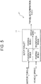
- Fig. 1 is a side view of a dump truck which is a representative example of work vehicles.
- the dump truck 100 illustrated in Fig. 1 which is used particularly in mine application, includes a frame 1 mounted thereon with a body 5 for loading of earth, sands and the like, in which the frame 1 and the body 5 are coupled by a pair of left and right hoist cylinders 6.
- the frame 1 is also mounted with a pair of left and right front wheels 2, a pair of left and right rear wheels 3, a fuel tank 9, and the like, through mechanism components which are not shown.
- a traveling motor 10 for driving the rear wheel 3 and a reduction gear for adjusting the rotational speed of the rear wheel 3 are incorporated.
- the frame 1 is further mounted with a deck D on which an operator can walk. Installed on the deck D are: a cab 4 into which the operator climbs for operation of the dump truck 100; a control cabinet 8 incorporating various electric power apparatuses; and a plurality of grid boxes 7 for dissipation of excess energy as heat. Installed in an area hidden behind the front wheel 2 in Fig.
- a first generator 12 serving as a power source for the traveling motors 10L, 10R for mainly driving the rear wheels 3
- a second generator 31 serving as a power source for fan motors (auxiliary motor) 35 which are mechanically connected to fans 36 for mainly cooling the interiors of the grid boxes 7
- a main pump although not shown in the figures, serving as a hydraulic source mainly for hydraulic apparatus; and the like.
- an accelerator pedal, a brake pedal, a hoist pedal, and a steering wheel are mounted within the cab 4, although not shown in the figures.
- the operator can operate the accelerator pedal or the brake pedal within the cab 4 to control the acceleration force or the braking force of the dump truck 100. Further, the operator performs the steering operation of the dump truck 100 by turning the steering wheel to the left or the right, and performs the dumping operation by depressing the hoist pedal so that the hoist cylinders 6 raise the body 5. It is noted that the hydraulic systems for performing the steering operation and the dumping operation are well known and thus not detailed.
- Fig. 2 is a schematic configuration diagram of the power regeneration system of a dump truck.
- the power regeneration system of the dump truck 100 includes the first generator 12 and the second generator 31 which are driven by the engine 11, a first electric circuit C1, a second electric circuit C2, a DC-DC converter 21 as a voltage step down converter, and a controller 51.
- the first electric circuit C1 supplies the power generated by the first generator 12 to the traveling motors 10L, 10R connected to the rear wheels (drive wheels) 3L, 3R of the dump truck 100.
- the electric circuit C2 supplies the power generated by the second generator 31 to each fan motor (auxiliary motor) 35 connected to the fan (auxiliary device) 36 of the dump truck 100.
- the DC-DC converter 21 is connected at the high voltage side to the first electric circuit C1 and at the low voltage side to the second electric circuit C2. And, the DC-DC converter 21 provides power from the first electric circuit C1 to the second electric circuit C2.
- the controller 51 controls driving of the DC-DC converter 21. To control driving of the DC-DC converter 21, as described later in detail, the controller 51 determines whether the travel mode of the dump truck 100 is in a powering mode corresponding to a normal traveling state or a regeneration mode corresponding to a traveling state where regenerative power is generated.
- first electric circuit C1 three phase AC output of the first generator 12 is input to the traveling motor inverters (first power conversion devices) 13L, 13R through a first rectifier circuit 14 which is a diode bridge. Outputs of the traveling motor inverters 13L, 13R are electrically connected to the travelling motors 10L, 10R, respectively.
- first rectifier circuit 14 for example, a bidirectional electric conversion device such as a three phase inverter may be used in lieu of the diode bridge.
- shafts of the traveling motors 10L, 10R are mechanically connected to the rear wheels 3L, 3R through the reduction gears G1, G2, respectively, so that the torques of the travelling motors 10L, 10R are transferred to the rear wheels 3L, 3R through the reduction gears G1, G2.
- a grid resistance box (resistor) 16 and a chopper 15 are connected to a high voltage DC line 18 which is a DC input section of the traveling motor inverters 13L, 13R, on the output side of the first rectifier circuit 14.
- an electric storage device for storing power regenerated at the traveling motors 10L, 10R is not connected to the first electric circuit C1.
- the copper 15 is actuated so that the regenerative power regenerated at the traveling motors 10L, 10R is dissipated into the atmosphere through the grid resistance box 16 in the grid boxes 7, without being stored in the electric storage device.
- a first voltage detector 17 detects a first voltage value of the high voltage DC line 18 and outputs it to the controller 51.
- a three phase AC output of the second generator 31 is connected to the fan motor inverter (second power conversion device) 34 through a second rectifier circuit 32 which is a diode bridge.
- An output of the fan motor inverter 34 is connected to a plurality of fan motors 35.
- an output shaft of each fan motor 35 is connected to the fan 36.
- a second voltage detector 37 detects a second voltage value of an auxiliary device DC line 38 and outputs it to the controller 51.
- a battery 33 is mounted for stable power of the auxiliary device DC line 38, but the battery 33 is not necessarily required.
- auxiliary device DC line 38 As an electric component connected to the auxiliary device DC line 38, only the fan motor inverter 34 is illustrated in the figure, but, for example, an electric conversion device performing power conversion of DC voltage such as an air conditioner inverter or an excitation power source of the first generator may be connected to the auxiliary device DC line 38.
- the controller 51 is configured by use of hardware including: a CPU (Central Processing Unit); a storage device such as HDD (Hard Disc Drive), ROM (Read Only Memory) for storing various programs to execute processing by the CPU, and the like; and RAM (Random Access Memory) providing a work area for the CPU to execute processing.
- a CPU Central Processing Unit
- HDD Hard Disc Drive
- ROM Read Only Memory
- RAM Random Access Memory
- the controller 51 receives as input: a voltage value V HV of the first electric circuit C1 detected by the first voltage detector 17; a current of the first electric circuit C1 detected by a first current detector which is not shown; torque T of the traveling motors 10L, 10R detected by torque sensors T1, T2; rotational speeds ⁇ of the traveling motors 10L, 10R detected by rotational speed sensors R1, R2; a vehicle speed V of the dump truck 100 detected by speed sensors S1, S2; a voltage value V LV of the second electric circuit C2 detected by the second voltage detector 37; and a current of the second electric circuit C2 detected by a second current detector which is not shown.
- the controller 51 outputs to the DC-DC converter 21 a control signal for controlling the voltage of the auxiliary device DC line 38 which is an output voltage of the DC-DC converter 21, based on the incoming current and voltage in the first electric circuit C1, the current and voltage in the second electric circuit C2, the torque T of the traveling motors 10L, 10R, and the vehicle speed V of the dump truck 100.
- the controller 51 Based on the state of the dump truck 100 and the operational input of the operator, the controller 51 also outputs an on/off signal as appropriate to each of semiconductor switches (not shown) of the engine 11, the traveling motor inverters 13L, 13R, the chopper 15 and the fan motor inverter 34 so that the traveling motors 10L, 10R, the grid resistance box 16 and the fan motors 35 are driven at appropriate timing in order to control the flow of current in the first electric circuit C1 and the second electric circuit C2.
- the three phase AC voltage generated is converted to a DC voltage by the first rectifier circuit 14, which then is input to the traveling motor inverters 13L, 13R.
- a control signal for acceleration is input from the controller 51 to the traveling motor inverters 13L, 13R, so that power is supplied to the traveling motors 10L, 10R.
- the traveling motors 10L, 10R drive the rear wheels 3L, 3R through the reduction gears G1, G2 to move the dump truck 100 forward or backward.
- a control signal for deceleration is input from the controller 51 to the traveling motor inverters 13L, 13R, so that the traveling motors 10L, 10R convert the kinetic energy of the dump truck 100 into electrical energy.
- the traveling motors 10L, 10R perform operation as generators.
- the power generated at this time (regenerative power) is stored as a DC voltage in the high voltage DC line 18 of the traveling motor inverters 13L, 13R, but because there is a limit to how the power can be stored with safety, a discharging function is necessary.
- the controller 51 effects the operation of the chopper 15 connected to the high voltage DC line 18. This allows the flow of electrical energy from the first generator 12 toward the traveling motors 10L, 10R to be switched to the flow from the traveling motors 10L, 10R toward the grid resistance box 16, so that the DC voltage is applied to the grid resistance box 16, thereby enabling consumption of the electrical energy as heat.
- the heat of the grid resistance box 16 is naturally air cooled by ambient atmosphere. However, if heat generating energy is high, the grid resistance box 16 may rise in temperature and this is likely to cause damage resulting from high temperature. To avoid this, the controller 51 drives the fans 36 to cool the grid resistance box 16 by forced air cooling.
- the three phase AC voltage generated is converted to a DC voltage by the second rectifier circuit 32, which then is input to the fan motor inverter 34. If the grid resistance box 16 is required to be cooled, a control signal for driving each fan motor 35 is input from the controller 51 to the fan motor inverter 34, so that the fans 36 rotate. Then, wind generated by the rotation of the fans 36 cools the grid resistance box 16.
- Fig. 3 is a schematic configuration diagram of the DC-DC converter 21.
- the high voltage DC line 18 is connected to high voltage side input terminals 41A, 41B of the DC-DC converter 21.
- the input terminals 41A, 41B of the DC-DC converter 21 are connected to a voltage inverter 43 which converts DC power to an AC signal such as with a rectangular waveform or the like, the voltage inverter 43 being comprised of, for example, a circuit, such as an insulated, voltage full bridge or the like.
- the voltage inverter 43 is connected to the primary winding of a transformer 44 with an insulation function such as, e.g., of a center tap type or the like, in which the AC signal generated at the voltage inverter 43 is transformed according to a turn ratio of the transformer 44 before being output to the secondary winding of the transformer 44.
- the secondary winding of the transformer 44 is connected to a rectifier circuit 45 which is composed of, for example, a diode and a choke coil.
- the AC signal output to the secondary winding of the transformer 44 is converted to DC voltage through the rectifier circuit 45 and then output to low-voltage side output terminals 42A, 42B.
- the output terminals 42A, 42B are connected to the auxiliary device DC line 38, so that the DC power is provided to the auxiliary device DC line 38.
- the circuit configuration of the DC-DC converter 21 may be a circuit configuration in which a voltage of the high voltage DC line 18 which is high voltage is converted to a voltage of the auxiliary device DC line 38 which is low voltage.
- Fig. 3 illustrates use of only one DC-DC converter, but a plurality of DC-DC converters may be connected in multiple parallel or multiple series.
- a voltage at the input terminals 41A, 41B on the high voltage side ranges from about 1800 V to about 2000 V
- a voltage at the output terminals 42A, 42B on the low voltage side ranges from about 320V to about 350 V.
- the DC-DC converter 21 functions as voltage step down means that steps down voltage from a high voltage side to a low voltage side.
- the controller 51 causes the travelling motors 10L, 10R to operate as generators to convert the kinetic energy into electrical energy, and then the electrical energy is converted to thermal energy through the grid resistance box 16 in order to obtain a braking force. Also, the generated heat is dissipated into the atmosphere through the forced air cooling by the fans 36 in order to ensure a stable braking force.
- the dump truck 100 has a mechanical brake system in addition to a retarder, and the speed of the vehicle body can be decreased by separately using the electrical deceleration (retarder brake) and the mechanical brake system depending on circumstances.
- Fig. 4 is a block diagram illustrating the control of each apparatus by the controller 51
- Fig. 5 is a block diagram for illustrating functionality of a travel determination section 61 illustrated in Fig. 4 .
- the controller 51 outputs a chopper drive instruction, a DC/DC duty* instruction and a second generator torque instruction to control each apparatus.
- a chopper drive instruction a DC/DC duty* instruction
- a second generator torque instruction a second generator torque instruction
- a travel determination section 61 determines the travel mode of the dump truck 100 based on the torque T and the vehicle speed V, the torque T being output from the torque sensors T1, T2 which detect torque of the traveling motors 10L, 10R, the vehicle speed V being output from the speed sensors S1, S2 which detect a vehicle speed of the dump truck 100. If the vehicle speed V is positive and also the toque T is positive or if the vehicle speed V is negative and also the torque T is negative, the travel determination section 61 determines that the travel mode is the powering mode, and the travel determination section 61 outputs a powering mode A.
- the travel mode is determined to be the regeneration mode, and the travel determination section 61 outputs a regeneration mode B. If the vehicle speed V is zero, this corresponds to a condition where the dump truck 100 stops or where the traveling motors 10L, 10R of the dump truck 100 on a slope generate only torque T, so that the travel determination section 61 outputs zero.
- the travel determination section 61 determines based on the torque T of the traveling motors 10L, 10R and the vehicle speed V of the dump truck 100 whether a current travel mode of the dump truck 100 is the powering mode corresponding to the normal traveling state or the regeneration mode corresponding to the traveling state where the regenerative power is generated.
- a resistor drive determination section 71 connected to the travel determination section 61 is connected to the first voltage detector 17 which detects the voltage of the high voltage DC line 18.
- the resistor drive determination section 71 holds a fourth threshold voltage value (fourth threshold value) V M1 that is predefined for driving of the chopper 15. If the output of the travel determination section 61 is the regeneration mode B and also a voltage value (first voltage value) V HV of the first voltage detector 17 exceeds V M1 (V HV > V M1 ), the resistor drive determination section 71 outputs 1.
- the resistor drive determination section 71 If the output of the travel determination section 61 is the powering mode A or zero or if a voltage value V HV of the first voltage detector 17 is equal to or less than V M1 (V HV ⁇ V M1 ), the resistor drive determination section 71 outputs zero. If the output of the resistor drive determination section 71 is 1, the controller 51 outputs a chopper drive instruction to start the chopper 15. Thus, the regenerative power is consumed through the grid resistance box 16. Meanwhile, if the output of the resistor drive determination section 71 is zero, the controller 51 outputs a chopper stop instruction to stop the chopper 15.
- a first threshold determination section 72 is connected to the switching section 74. If the output of the travel determination section 61 is A and the powering mode, the first threshold determination section 72 outputs a first threshold voltage instruction value (first threshold value) V A* required for the high voltage DC line 18, based on a pre-held torque-rotational speed table for the traveling motors 10L, 10R in the powering mode.
- a second threshold determination section 73 is connected to the switching section 74. If the output of the travel determination section 61 is B and the regeneration mode, the second threshold determination section 73 outputs a second threshold voltage instruction value (second threshold value) V B* required for the high voltage DC line 18, based on a pre-held torque-rotational speed table for the traveling motors 10L, 10R in the regeneration mode.
- a DC-DC converter drive determination section 75 is connected to the first threshold determination section 72 and the second threshold determination section 73, and receives as input the calculated first threshold voltage instruction value V A* , the calculated second threshold voltage instruction value V B* , and the voltage value V HV which is the output of the first voltage detector 17 of the high voltage DC line 18. If the voltage value V HV of the first voltage detector 17 of the high voltage DC line 18 exceeds V A* or V B* (V HV > V A* or V B* ), the DC-DC converter drive determination section 75 outputs 1.
- the DC-DC converter drive determination section 75 outputs zero.
- the DC-DC converter drive determination section 75 also pre-holds a maximum voltage value V M2 , and if the voltage value V HV of the first voltage detector 17 of the high voltage DC line 18 is equal to or greater than V M2 (V HV ⁇ V M2 ), the DC-DC converter drive determination section 75 outputs zero.
- a DC-DC converter voltage control section 91 includes a subtracter 82, a PI control section 83 and a limiter 84.
- the subtracter 82 receives as input a voltage value (second voltage value) V LV which is the output of the second voltage detector 37 of the auxiliary device DC line 38, and a voltage instruction value V LV* for the auxiliary device DC line 38.
- the subtracter 82 performs a subtraction between the voltage instruction value V LV* and the voltage value V LV of the second voltage detector 37, and outputs a voltage deviation ⁇ V LV to the PI control section 83.
- the PI control section 83 outputs to the limiter 84 a Duty value at which the voltage deviation ⁇ V LV becomes zero.
- the limiter 84 has a function of placing a limit to a Duty* value output from the PI control section 83.
- Duty* value output from the PI control section 83 is equal to or greater than a maximum limiter value Duty_max (Duty* ⁇ Duty_max), the limiter 84 outputs Duty_max to a DC-DC converter control section 87. However, if the Duty value output from the PI control section 83 is equal to or less than a minimum limiter value Duty_min (Duty* ⁇ Duty_min), the limiter 84 outputs Duty_min to the DC-DC converter control section 87.
- the limiter 84 If the Duty* value output from the PI control section 83 falls within limits of values of the limiter 84 (Duty_min ⁇ Duty* ⁇ Duty_max), the limiter 84 outputs to the DC-DC converter control section 87 the Duty* value output from the PI control section 83.
- the voltage value (second voltage value) V LV which is the output of the second voltage detector 37 of the auxiliary device DC line 38 is input to a third threshold determination section 81.
- the third threshold determination section 81 pre-holds a maximum voltage value (third threshold value) V C for the auxiliary device DC line 38.
- the third threshold determination section 81 performs a comparison between the maximum voltage value V C for the auxiliary device DC line 38 and the voltage value V LV of the second voltage detector 37 of the auxiliary device DC line 38.
- the third threshold determination section 81 outputs zero, whereas if the voltage value V LV is less than the maximum voltage value V C for the auxiliary device DC line 38 (V LV ⁇ V C ), the third threshold determination section 81 outputs 1.
- the DC-DC converter control section 87 receives as input the output of the DC-DC converter drive determination section 75, the output of the limiter 84 and the output of the third threshold determination section 81. If either one of the condition where the DC-DC converter drive determination section 75 outputs zero or the condition where the third threshold determination section 81 outputs zero is satisfied, the DC-DC converter control section 87 outputs zero to stop the driving of the DC-DC converter 21. If the DC-DC converter drive determination section 75 outputs 1 and also the third threshold determination section 81 outputs 1, the DC-DC converter control section 87 outputs the output value of the limiter 84 (i.e., Duty* value) to drive the DC-DC converter 21.
- the DC-DC converter control section 87 outputs the output value of the limiter 84 (i.e., Duty* value) to drive the DC-DC converter 21.
- a second generator torque control section 92 includes a subtracter 82, a PI control section 85 and a limiter 86.
- the subtracter 82 receives as input a voltage value V LV which is the output of the second voltage detector 37 of the auxiliary device DC line 38, and a voltage instruction value V LV* for the auxiliary device DC line 38.
- the subtracter 82 performs a subtraction between the voltage instruction value V LV* and the voltage value V LV , and outputs a voltage deviation ⁇ V LV to the PI control section 85.
- the PI control section 85 outputs to the limiter 86 a torque instruction value T 2* at which the voltage deviation ⁇ V LV becomes zero.
- the limiter 86 has a function of placing a limit to a torque instruction value T 2* output from the PI control section 85. If the torque instruction value T 2* output from the PI control section 85 is equal to or greater than a maximum limiter value T_max (T 2* ⁇ T_max), the limiter 86 outputs T_max. However, if the torque instruction value T 2* output from the PI control section 85 is equal to or less than a minimum limiter value T_min (T 2* ⁇ T_min), the limiter 86 outputs T_min.
- the limiter 86 If the torque instruction value T 2* output from the PI control section 85 falls within limits of values of the limiter 86 (T_min ⁇ T 2* ⁇ T_max), the limiter 86 outputs the torque instruction value T 2* output from the PI control section 85. In compliance with the torque instruction value T 2* output from the limiter 86, the second generator 31 generates electric power by the engine 11.
- Fig. 6 is a flowchart illustrating steps of controlling the DC-DC converter 21 by the controller 51. As illustrated in Fig. 6 , the controller 51 determines whether or not the voltage value V LV of the auxiliary device DC line 38 is less than the maximum voltage value (third threshold voltage) V C for the auxiliary device DC line 38 (S1).
- V LV is less than V C (YES at S1)
- the controller 51 determines from the torque T of the traveling motors 10L, 10R and the vehicle speed V of the dump truck 100 whether the travel mode of the dump truck 100 is the powering mode or the regeneration mode, and the controller 51 calculates a voltage threshold value (a first threshold voltage instruction value V A* , a second threshold voltage instruction value V B* ) for the high voltage DC line 18 (S2).
- the controller 51 determines whether or not the voltage value V HV of the high voltage DC line 18 is greater than the second threshold voltage instruction value V B* (S4). If it is greater (YES at S4), the controller 51 drives the DC-DC converter 21 in accordance with the Duty* value in the regeneration mode (S5). Meanwhile, if the travel mode is the powering mode (YES at S6), the controller 51 determines whether or not the voltage value V HV of the high voltage DC line 18 is greater than the first threshold voltage instruction value V A* (S7). If it is greater (YES at S7), the controller 51 drives the DC-DC converter 21 in accordance with the Duty* value in the powering mode (S8). It is noted that if NO in S4, NO in S6, and NO in S7, the controller 51 does not drive (stops) the DC-DC converter 21.
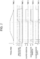
- Fig. 7 is a time chart illustrating the traveling state of the dump truck 100 and timing for operating each apparatus.
- the traveling motor inverters 13L, 13R drive, and the traveling motors 10L, 10R are driven, so that the first generator 12 generates electric power, and the high voltage DC line 18 rises in voltage.
- the dump truck 100 While the dump truck 100 is traveling, when the first generator 12 generates a larger amount of power than required to drive the traveling motors 10L, 10R, the voltage of the high voltage DC line 18 increases beyond the voltage instruction value required to drive the traveling motors. At this time, the dump truck is in the powering mode and also the detected voltage of the high voltage DC line exceeds the first threshold voltage instruction value V A* , so that the DC-DC converter 21 is driven. The DC-DC converter 21 provides surplus power generated by the first generator 12, to the auxiliary device DC line 38. At this time, the output of the second generator 31 reduces.
- the detected voltage of the high voltage DC line 18 is equal to the first threshold voltage instruction value V A* , and the DC-DC converter 21 stops operating.
- the dump truck 100 Upon the dump truck 100 starting to decelerate, the dump truck 100 enters the regeneration mode.
- the DC-DC converter 21 drives.
- the DC-DC converter 21 provides to the auxiliary device DC line 38 the regenerative power from the traveling motors 10L, 10R. At this time, the output of the second generator 31 reduces.
- the chopper 15 drives to control the voltage of the high voltage DC line 18 to be prevented from exceeding the maximum voltage value V M1 .
- the traveling motors 10L, 10R are in the regeneration mode, without use of a battery for the high voltage DC line 18, the electric power generated in retarding (during braking by retarder brake) can be consumed at the grid resistance box 16. And, because of the unnecessity of mounting a battery in the high voltage DC line 18, a reduction in weight of the dump truck 100 can be achieved.
- the regenerative power can be consumed irrespective of the magnitude of power generated during retarding and the rate of output variations, and also providing a portion of the electric power of the retarder to the auxiliary device DC line 38 via the DC-DC converter 21 enables the consumption of the regenerative power by the auxiliary device DC line 38.
- the traveling motors 10L, 10R are in the powering mode, a portion of the energy generated by the engine 11 and the first generator 12 can be provided to the auxiliary device DC line 38 via the DC-DC converter 21, and a rise in voltage in the high voltage DC line 18 due to the surplus power during the powering can be reduced.
- This enables a reduction in output of the second generator 31 as well as of the engine 11, which in turn contributes to improved fuel efficiency of the dump truck 100 and improved safety of the dump truck 100.
- the DC-DC converter 21 is able to be driven to provide the surplus power from the first electric circuit C1 to the second electric circuit C2 immediately (without waiting for the completion of charging to a battery) every time the travel mode of the dump truck 100 is switched from the powering mode to the regeneration mode or vice versa. This may provide further effective use of energy as compared with the conventional art. In short, by switching the operation of the DC-DC converter 21 depending on the travel mode, the regenerative power can be immediately provided to the auxiliary devices for consumption.
- the controller 51 is able to control the engine rotational speed with consideration given to engine efficiency.
- a description is given with reference to a characteristic graph between engine rotational speed and engine output illustrated in Fig. 8 .
- the controller 51 controls such that the engine rotational speed slightly increases from N1 to N2. This makes it possible to increase the engine efficiency to improve fuel efficiency. It is noted that this advantageous effect is more remarkably generated when the power regeneration system according to the present invention is applied to a wheel loader which is a work vehicle. This is because a wheel loader is repeatedly operated for so-called "V-shaped excavation".
- a destination to which the power is provided from the DC-DC converter 21 is described as the fan motors 35 in the first embodiment, but it may be a traveling motor blower or a first generator blower for blowing air to cool the traveling motors 10L, 10R or the first generator 12, or an excitation power supply for the first generator 12, all of which are not shown in the figures.
- a travel determination section 62 illustrated in Fig. 9 may be applied instead of the travel determination section 61 illustrated in Fig. 5 .
- Fig. 9 is a block diagram for illustrating functionality of the travel determination section 62. As illustrated in Fig. 9 , the travel determination section 62 determines the travel mode of the dump truck 100 based on: a vehicle speed V -1 at the previous sampling output from the speed sensors S1, S2 which detect a vehicle speed V of the dump truck 100 at certain time T1; and a vehicle speed V of the dump truck 100 being detected at certain time T2 (T1 ⁇ T2).
- the travel determination section 62 determines that the travel mode is the powering mode and outputs a powering mode A.
- the travel determination section 62 determines that the travel mode is the regeneration mode and outputs a regeneration mode B.
- the travel mode of the dump truck 100 is able to be determined even in the configuration of the travel determination section 62.
- a tilting angle sensor not shown, may be used in combination to sense a tilt of the vehicle body so that a speed reduction such as on an uphill slope or the like is not determined as the regeneration mode.
- the travel determination section 62 may be used in lieu of the travel determination section 61, or alternatively may be used in combination with the travel determination section 61.
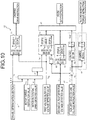
- Fig. 10 is a schematic configuration diagram of a power regeneration system according to a second embodiment of the present invention.
- a major difference from the first embodiment is a method of setting a first threshold voltage instruction value V A* in the powering mode in the DC-DC converter drive determination section 75.
- a DC-DC converter minimum drive setting section 88 receives as input a voltage value V LV of the auxiliary device DC line 38. Based on the incoming voltage value V LV of the auxiliary device DC line 38, the DC-DC converter minimum drive setting section 88 calculates a first threshold voltage instruction value V A* for the high voltage DC line 18 at which the voltage value V LV of the auxiliary device DC line 38 can be output by the DC-DC converter 21.
- the calculation method is presented by equation (1), in which a turn ratio of a transformer of the DC-DC converter 21 is N and a maximum Duty ratio is Duty_max.
- V A ⁇ V LV ⁇ N / Duty _ max
- the DC-DC converter minimum drive setting section 88 outputs a calculated first threshold voltage instruction value V A* for the high voltage DC line 18 to the DC-DC converter drive determination section 75.
- the DC-DC converter drive determination section 75 is connected to the second threshold determination section 73 and the DC-DC converter minimum drive setting section 88, and receives as input the calculated first threshold voltage instruction value V A* , the calculated second threshold voltage instruction value V B* , and the voltage value V HV which is the output of the first voltage detector 17 of the high voltage DC line.
- the DC-DC converter drive determination section 75 If the voltage value V HV of the first voltage detector 17 of the high voltage DC line 18 exceeds the first threshold voltage instruction value V A* or the second threshold voltage instruction value V B* (V HV > V A* or V B* ), the DC-DC converter drive determination section 75 outputs 1. If the voltage value V HV of the first voltage detector 17 of the high voltage DC line 18 is equal to or less than V A* or V B* (V HV ⁇ V A* or V B* ), the DC-DC converter drive determination section 75 outputs zero.
- the DC-DC converter drive determination section 75 also pre-holds a maximum voltage value V M2 , and if the voltage value V HV of the first voltage detector 17 of the high voltage DC line 18 is equal to or greater than V M2 (V HV ⁇ V M2 ), the DC-DC converter drive determination section 75 outputs zero.
- Fig. 11 is a time chart illustrating the traveling state of the dump truck 100 and timing for operating each apparatus.
- the traveling motor inverters 13L, 13R drive, and the traveling motors 10L, 10R are driven, so that the first generator 12 generates electric power, and the high voltage DC line 18 rises in voltage.
- the dump truck 100 While the dump truck 100 is traveling, the dump truck 100 is in the powering mode and also the detected voltage of the high voltage DC line 18 is equal to or greater than the first threshold voltage instruction value V A* , so that the DC-DC converter 21 is driven.
- the DC-DC converter 21 provides to the auxiliary device DC line 38 surplus power generated by the first generator 12. At this time, the output of the second generator 31 reduces.
- the detected voltage of the high voltage DC line 18 is equal to the first threshold voltage instruction value V A* , and the DC-DC converter 21 does not operate.
- the dump truck 100 Upon the dump truck 100 starting to decelerate, the dump truck 100 enters the regeneration mode.
- the DC-DC converter 21 drives.
- the DC-DC converter 21 provides to the auxiliary device DC line 38 the regenerative power from the traveling motors 10L, 10R. At this time, the output of the second generator 31 reduces.
- the chopper 15 drives so that the voltage of the high voltage DC line is controlled to be prevented from exceeding the maximum voltage value V M1 .
- the present invention is not limited to the embodiments described above, and various modifications are embraced.
- the above-described embodiments have been described in detail for the purpose of providing easy understanding of the present invention, and the present invention is not necessarily limited to including all the configurations described above.
- the present invention is applicable to various types of work vehicles such as a wheel loader, a fork lift and the like as described above, in addition to the dump truck.
Abstract
Description
- The present invention relates to a power regeneration system of a work vehicle.
- As background art of the present invention, for example,
Patent Literature 1 discloses "a hybrid dump truck including: drive motors that drive drive wheels; an engine that rotationally drives a generator for power generation; a rectifier that converts an alternating current output from the generator into a direct current; an inverter that is connected to a DC output line of the rectifier and controls the rotational speeds of the drive motors; a battery that is connected in parallel to the DC output line of the rectifier and an input power-source line of the inverter; and a controller that outputs a speed instruction signal to the inverter according to an acceleration quantity, in which each drive motor has maximum output greater than the engine, and the controller has battery charge/discharge controlling means that, when a larger amount of power than that generated at maximum output of the engine is required for driving of the drive motors, outputs an instruction to a battery open/close switch to allow the battery to discharge in order to use the discharge current to assist the drive power of the drive motors" (see Abstract). - Patent Literature 1:
JP-A-No. 2000-299901 - In
Patent Literature 1, many batteries must be connected in series because the batteries (e.g., lithium ion batteries, lead-acid batteries and the like) are configured to be mounted in a high voltage DC line in an electric circuit. Specifically, inPatent Literature 1, as the batteries increase in number, the weight of the dump truck is increased, resulting in a problem of a decrease in fuel efficiency. - Accordingly, there is a need in a power regeneration system for work vehicles for a technique to enable an effective use of regenerative power without an electric storage device, such as a battery and the like, mounted in a high voltage DC line.
- To address this problem, in representative embodiments of the present invention, a power regeneration system of a work vehicle is provided which includes: a first generator and a second generator that are driven by an engine; a first electric circuit for supplying electric power generated at the first generator, to traveling motors connected to drive wheels of the work vehicle; a second electric circuit for supplying electric power generated at the second generator, to an auxiliary device of the work vehicle; a voltage step down converter that is connected at a high voltage side to the first electric circuit and connected at a low voltage side to the second electric circuit, the voltage step down converter providing electric power from the first electric circuit to the second electric circuit; and a controller that determines whether a travel mode of the work vehicle is a powering mode or a regeneration mode in order to control driving of the voltage step down converter, the powering mode corresponding to a normal traveling state, the regeneration mode corresponding to a traveling state where regenerative power is generated. If the travel mode of the work vehicle is the regeneration mode, the controller controls driving of the voltage step down converter to provide the regenerative power from the first electric circuit through the voltage step down converter to the second electric circuit, in order to drive the auxiliary device with the regenerative power.
- According to the present invention, in a power regeneration system of a work vehicle, an effective use of regenerative power is enabled without an electric storage device, such as a battery and the like, mounted in a high voltage DC line. It is noted that the above and other aspects, features and advantages will be more apparent from the following description of embodiments.
-
- [
Fig. 1] Fig. 1 is a side view of a dump truck which is a representative example of work vehicles. - [
Fig. 2] Fig. 2 is a schematic configuration diagram of a power regeneration system of a dump truck. - [
Fig. 3] Fig. 3 is a schematic configuration diagram of a DC-DC converter. - [
Fig. 4] Fig. 4 is a block diagram illustrating control of each apparatus by a controller. - [
Fig. 5] Fig. 5 is a block diagram for illustrating functionality of a travel determination section. - [
Fig. 6] Fig. 6 is a flowchart illustrating steps of controlling the DC-DC converter by the controller. - [
Fig. 7] Fig. 7 is a time chart illustrating a traveling state of a dump truck and timing for operating each apparatus. - [
Fig. 8] Fig. 8 is a characteristic graph showing the relationship between engine rotational speed and engine output. - [
Fig. 9] Fig. 9 is a block diagram for illustrating functionality of a travel determination section. - [
Fig. 10] Fig. 10 is a schematic configuration diagram of a power regeneration system according to a second embodiment of the present invention. - [
Fig. 11] Fig. 11 is a time chart illustrating a traveling state of a dump truck and timing for operating each apparatus. - Embodiments according to the present invention will now be described with reference to the accompanying drawings. It is noted that, throughout the drawings, like reference signs are used to refer to like elements, and a repetitive description thereof is omitted.
- A first embodiment of a power regeneration system of a work vehicle according to the present invention will described below. The power regeneration system according to the first embodiment of the present invention is described as an example of applying a power regeneration system to a dump truck which is a representative example of work vehicles.
-
Fig. 1 is a side view of a dump truck which is a representative example of work vehicles. Thedump truck 100 illustrated inFig. 1 , which is used particularly in mine application, includes aframe 1 mounted thereon with abody 5 for loading of earth, sands and the like, in which theframe 1 and thebody 5 are coupled by a pair of left andright hoist cylinders 6. Theframe 1 is also mounted with a pair of left and rightfront wheels 2, a pair of left and rightrear wheels 3, a fuel tank 9, and the like, through mechanism components which are not shown. In a rotation axis portion of eachrear wheel 3, a travelingmotor 10 for driving therear wheel 3, and a reduction gear for adjusting the rotational speed of therear wheel 3 are incorporated. - The
frame 1 is further mounted with a deck D on which an operator can walk. Installed on the deck D are: acab 4 into which the operator climbs for operation of thedump truck 100; acontrol cabinet 8 incorporating various electric power apparatuses; and a plurality ofgrid boxes 7 for dissipation of excess energy as heat. Installed in an area hidden behind thefront wheel 2 inFig. 1 are: anengine 11; afirst generator 12 serving as a power source for thetraveling motors rear wheels 3; asecond generator 31 serving as a power source for fan motors (auxiliary motor) 35 which are mechanically connected tofans 36 for mainly cooling the interiors of thegrid boxes 7; a main pump, although not shown in the figures, serving as a hydraulic source mainly for hydraulic apparatus; and the like. - Within the
cab 4, although not shown in the figures, an accelerator pedal, a brake pedal, a hoist pedal, and a steering wheel are mounted. The operator can operate the accelerator pedal or the brake pedal within thecab 4 to control the acceleration force or the braking force of thedump truck 100. Further, the operator performs the steering operation of thedump truck 100 by turning the steering wheel to the left or the right, and performs the dumping operation by depressing the hoist pedal so that thehoist cylinders 6 raise thebody 5. It is noted that the hydraulic systems for performing the steering operation and the dumping operation are well known and thus not detailed. -
Fig. 2 is a schematic configuration diagram of the power regeneration system of a dump truck. As illustrated inFig. 2 , the power regeneration system of thedump truck 100 includes thefirst generator 12 and thesecond generator 31 which are driven by theengine 11, a first electric circuit C1, a second electric circuit C2, a DC-DC converter 21 as a voltage step down converter, and acontroller 51. - The first electric circuit C1 supplies the power generated by the
first generator 12 to thetraveling motors dump truck 100. The electric circuit C2 supplies the power generated by thesecond generator 31 to each fan motor (auxiliary motor) 35 connected to the fan (auxiliary device) 36 of thedump truck 100. - The DC-
DC converter 21 is connected at the high voltage side to the first electric circuit C1 and at the low voltage side to the second electric circuit C2. And, the DC-DC converter 21 provides power from the first electric circuit C1 to the second electric circuit C2. Thecontroller 51 controls driving of the DC-DC converter 21. To control driving of the DC-DC converter 21, as described later in detail, thecontroller 51 determines whether the travel mode of thedump truck 100 is in a powering mode corresponding to a normal traveling state or a regeneration mode corresponding to a traveling state where regenerative power is generated. - In the first electric circuit C1, three phase AC output of the
first generator 12 is input to the traveling motor inverters (first power conversion devices) 13L, 13R through afirst rectifier circuit 14 which is a diode bridge. Outputs of thetraveling motor inverters travelling motors first rectifier circuit 14, for example, a bidirectional electric conversion device such as a three phase inverter may be used in lieu of the diode bridge. - Also, shafts of the
traveling motors rear wheels travelling motors rear wheels - A grid resistance box (resistor) 16 and a
chopper 15 are connected to a highvoltage DC line 18 which is a DC input section of thetraveling motor inverters first rectifier circuit 14. Here, an electric storage device for storing power regenerated at thetraveling motors copper 15 is actuated so that the regenerative power regenerated at thetraveling motors grid resistance box 16 in thegrid boxes 7, without being stored in the electric storage device. Also afirst voltage detector 17 detects a first voltage value of the highvoltage DC line 18 and outputs it to thecontroller 51. - Meanwhile, in the second electric circuit C2, a three phase AC output of the
second generator 31 is connected to the fan motor inverter (second power conversion device) 34 through asecond rectifier circuit 32 which is a diode bridge. An output of thefan motor inverter 34 is connected to a plurality offan motors 35. Also, an output shaft of eachfan motor 35 is connected to thefan 36. And, asecond voltage detector 37 detects a second voltage value of an auxiliarydevice DC line 38 and outputs it to thecontroller 51. Here, in the first embodiment, abattery 33 is mounted for stable power of the auxiliarydevice DC line 38, but thebattery 33 is not necessarily required. It is noted that, in the first embodiment, as an electric component connected to the auxiliarydevice DC line 38, only thefan motor inverter 34 is illustrated in the figure, but, for example, an electric conversion device performing power conversion of DC voltage such as an air conditioner inverter or an excitation power source of the first generator may be connected to the auxiliarydevice DC line 38. - As illustrated in
Fig. 2 , thecontroller 51 is configured by use of hardware including: a CPU (Central Processing Unit); a storage device such as HDD (Hard Disc Drive), ROM (Read Only Memory) for storing various programs to execute processing by the CPU, and the like; and RAM (Random Access Memory) providing a work area for the CPU to execute processing. - The
controller 51 receives as input: a voltage value VHV of the first electric circuit C1 detected by thefirst voltage detector 17; a current of the first electric circuit C1 detected by a first current detector which is not shown; torque T of the travelingmotors motors dump truck 100 detected by speed sensors S1, S2; a voltage value VLV of the second electric circuit C2 detected by thesecond voltage detector 37; and a current of the second electric circuit C2 detected by a second current detector which is not shown. - The
controller 51 outputs to the DC-DC converter 21 a control signal for controlling the voltage of the auxiliarydevice DC line 38 which is an output voltage of the DC-DC converter 21, based on the incoming current and voltage in the first electric circuit C1, the current and voltage in the second electric circuit C2, the torque T of the travelingmotors dump truck 100. - Based on the state of the
dump truck 100 and the operational input of the operator, thecontroller 51 also outputs an on/off signal as appropriate to each of semiconductor switches (not shown) of theengine 11, the travelingmotor inverters chopper 15 and thefan motor inverter 34 so that the travelingmotors grid resistance box 16 and thefan motors 35 are driven at appropriate timing in order to control the flow of current in the first electric circuit C1 and the second electric circuit C2. - Upon the
engine 11 driving thefirst generator 12, the three phase AC voltage generated is converted to a DC voltage by thefirst rectifier circuit 14, which then is input to the travelingmotor inverters controller 51 to the travelingmotor inverters motors motors rear wheels dump truck 100 forward or backward. - Meanwhile, when the operator depresses the brake pedal or in the braking operation for downhill travel, a control signal for deceleration is input from the
controller 51 to the travelingmotor inverters motors dump truck 100 into electrical energy. As another stated, the travelingmotors - The power generated at this time (regenerative power) is stored as a DC voltage in the high
voltage DC line 18 of the travelingmotor inverters controller 51 effects the operation of thechopper 15 connected to the highvoltage DC line 18. This allows the flow of electrical energy from thefirst generator 12 toward the travelingmotors motors grid resistance box 16, so that the DC voltage is applied to thegrid resistance box 16, thereby enabling consumption of the electrical energy as heat. - Typically, the heat of the
grid resistance box 16 is naturally air cooled by ambient atmosphere. However, if heat generating energy is high, thegrid resistance box 16 may rise in temperature and this is likely to cause damage resulting from high temperature. To avoid this, thecontroller 51 drives thefans 36 to cool thegrid resistance box 16 by forced air cooling. - Meanwhile, upon the
engine 11 driving thesecond generator 31, the three phase AC voltage generated is converted to a DC voltage by thesecond rectifier circuit 32, which then is input to thefan motor inverter 34. If thegrid resistance box 16 is required to be cooled, a control signal for driving eachfan motor 35 is input from thecontroller 51 to thefan motor inverter 34, so that thefans 36 rotate. Then, wind generated by the rotation of thefans 36 cools thegrid resistance box 16. - Next, the configuration of the DC-
DC converter 21 is described.Fig. 3 is a schematic configuration diagram of the DC-DC converter 21. As illustrated inFig. 3 , the highvoltage DC line 18 is connected to high voltageside input terminals DC converter 21. Theinput terminals DC converter 21 are connected to avoltage inverter 43 which converts DC power to an AC signal such as with a rectangular waveform or the like, thevoltage inverter 43 being comprised of, for example, a circuit, such as an insulated, voltage full bridge or the like. Thevoltage inverter 43 is connected to the primary winding of atransformer 44 with an insulation function such as, e.g., of a center tap type or the like, in which the AC signal generated at thevoltage inverter 43 is transformed according to a turn ratio of thetransformer 44 before being output to the secondary winding of thetransformer 44. The secondary winding of thetransformer 44 is connected to arectifier circuit 45 which is composed of, for example, a diode and a choke coil. The AC signal output to the secondary winding of thetransformer 44 is converted to DC voltage through therectifier circuit 45 and then output to low-voltageside output terminals output terminals device DC line 38, so that the DC power is provided to the auxiliarydevice DC line 38. - It is noted that the circuit configuration of the DC-
DC converter 21 may be a circuit configuration in which a voltage of the highvoltage DC line 18 which is high voltage is converted to a voltage of the auxiliarydevice DC line 38 which is low voltage. Also,Fig. 3 illustrates use of only one DC-DC converter, but a plurality of DC-DC converters may be connected in multiple parallel or multiple series. For information, in the embodiment, a voltage at theinput terminals output terminals DC converter 21 functions as voltage step down means that steps down voltage from a high voltage side to a low voltage side. - In this manner, in the braking operation of the
dump truck 100, thecontroller 51 causes the travellingmotors grid resistance box 16 in order to obtain a braking force. Also, the generated heat is dissipated into the atmosphere through the forced air cooling by thefans 36 in order to ensure a stable braking force. - It is noted that, although not shown, the
dump truck 100 has a mechanical brake system in addition to a retarder, and the speed of the vehicle body can be decreased by separately using the electrical deceleration (retarder brake) and the mechanical brake system depending on circumstances. - The following description is of the control of each of apparatuses including the DC-
DC converter 21 by thecontroller 51.Fig. 4 is a block diagram illustrating the control of each apparatus by thecontroller 51, andFig. 5 is a block diagram for illustrating functionality of atravel determination section 61 illustrated inFig. 4 . As illustrated inFig. 4 , thecontroller 51 outputs a chopper drive instruction, a DC/DC duty* instruction and a second generator torque instruction to control each apparatus. The following is a detailed description. - As illustrated in
Fig. 5 , atravel determination section 61 determines the travel mode of thedump truck 100 based on the torque T and the vehicle speed V, the torque T being output from the torque sensors T1, T2 which detect torque of the travelingmotors dump truck 100. If the vehicle speed V is positive and also the toque T is positive or if the vehicle speed V is negative and also the torque T is negative, thetravel determination section 61 determines that the travel mode is the powering mode, and thetravel determination section 61 outputs a powering mode A. If the vehicle speed V is positive and also the toque T is negative or if the vehicle speed V is negative and also the torque T is positive, the travel mode is determined to be the regeneration mode, and thetravel determination section 61 outputs a regeneration mode B. If the vehicle speed V is zero, this corresponds to a condition where thedump truck 100 stops or where the travelingmotors dump truck 100 on a slope generate only torque T, so that thetravel determination section 61 outputs zero. - In this manner, the
travel determination section 61 determines based on the torque T of the travelingmotors dump truck 100 whether a current travel mode of thedump truck 100 is the powering mode corresponding to the normal traveling state or the regeneration mode corresponding to the traveling state where the regenerative power is generated. - As illustrated in
Fig. 4 , a resistordrive determination section 71 connected to thetravel determination section 61 is connected to thefirst voltage detector 17 which detects the voltage of the highvoltage DC line 18. The resistordrive determination section 71 holds a fourth threshold voltage value (fourth threshold value) VM1 that is predefined for driving of thechopper 15. If the output of thetravel determination section 61 is the regeneration mode B and also a voltage value (first voltage value) VHV of thefirst voltage detector 17 exceeds VM1 (VHV > VM1), the resistordrive determination section 71outputs 1. - If the output of the
travel determination section 61 is the powering mode A or zero or if a voltage value VHV of thefirst voltage detector 17 is equal to or less than VM1 (VHV ≤ VM1), the resistordrive determination section 71 outputs zero. If the output of the resistordrive determination section 71 is 1, thecontroller 51 outputs a chopper drive instruction to start thechopper 15. Thus, the regenerative power is consumed through thegrid resistance box 16. Meanwhile, if the output of the resistordrive determination section 71 is zero, thecontroller 51 outputs a chopper stop instruction to stop thechopper 15. - A switching
section 74 is connected to thetravel determination section 61 and receives as input: a travel determination result (A, B, 0) from thetravel determination section 61; a torque instruction value T* for the travelingmotors motors motors section 74 computes a required power P(= T×ω) for the travelingmotors switching section 74 outputs the required power P and the information received from thetravel determination section 61. - A first
threshold determination section 72 is connected to theswitching section 74. If the output of thetravel determination section 61 is A and the powering mode, the firstthreshold determination section 72 outputs a first threshold voltage instruction value (first threshold value) VA* required for the highvoltage DC line 18, based on a pre-held torque-rotational speed table for the travelingmotors - A second
threshold determination section 73 is connected to theswitching section 74. If the output of thetravel determination section 61 is B and the regeneration mode, the secondthreshold determination section 73 outputs a second threshold voltage instruction value (second threshold value) VB* required for the highvoltage DC line 18, based on a pre-held torque-rotational speed table for the travelingmotors - A DC-DC converter
drive determination section 75 is connected to the firstthreshold determination section 72 and the secondthreshold determination section 73, and receives as input the calculated first threshold voltage instruction value VA*, the calculated second threshold voltage instruction value VB*, and the voltage value VHV which is the output of thefirst voltage detector 17 of the highvoltage DC line 18. If the voltage value VHV of thefirst voltage detector 17 of the highvoltage DC line 18 exceeds VA* or VB* (VHV > VA* or VB*), the DC-DC converterdrive determination section 75outputs 1. Meanwhile, if the voltage value VHV of thefirst voltage detector 17 of the highvoltage DC line 18 is equal to or less than VA* or VB* (VHV ≤ VA* or VB*), the DC-DC converterdrive determination section 75 outputs zero. The DC-DC converterdrive determination section 75 also pre-holds a maximum voltage value VM2, and if the voltage value VHV of thefirst voltage detector 17 of the highvoltage DC line 18 is equal to or greater than VM2 (VHV ≥ VM2), the DC-DC converterdrive determination section 75 outputs zero. - A DC-DC converter
voltage control section 91 includes asubtracter 82, aPI control section 83 and alimiter 84. Thesubtracter 82 receives as input a voltage value (second voltage value) VLV which is the output of thesecond voltage detector 37 of the auxiliarydevice DC line 38, and a voltage instruction value VLV* for the auxiliarydevice DC line 38. Thesubtracter 82 performs a subtraction between the voltage instruction value VLV* and the voltage value VLV of thesecond voltage detector 37, and outputs a voltage deviation ΔVLV to thePI control section 83. ThePI control section 83 outputs to the limiter 84 a Duty value at which the voltage deviation ΔVLV becomes zero. Thelimiter 84 has a function of placing a limit to a Duty* value output from thePI control section 83. - If the Duty* value output from the
PI control section 83 is equal to or greater than a maximum limiter value Duty_max (Duty* ≥ Duty_max), thelimiter 84 outputs Duty_max to a DC-DCconverter control section 87. However, if the Duty value output from thePI control section 83 is equal to or less than a minimum limiter value Duty_min (Duty* ≤ Duty_min), thelimiter 84 outputs Duty_min to the DC-DCconverter control section 87. If the Duty* value output from thePI control section 83 falls within limits of values of the limiter 84 (Duty_min < Duty* < Duty_max), thelimiter 84 outputs to the DC-DCconverter control section 87 the Duty* value output from thePI control section 83. - Also, the voltage value (second voltage value) VLV which is the output of the
second voltage detector 37 of the auxiliarydevice DC line 38 is input to a thirdthreshold determination section 81. The thirdthreshold determination section 81 pre-holds a maximum voltage value (third threshold value) VC for the auxiliarydevice DC line 38. The thirdthreshold determination section 81 performs a comparison between the maximum voltage value VC for the auxiliarydevice DC line 38 and the voltage value VLV of thesecond voltage detector 37 of the auxiliarydevice DC line 38. Then, if the voltage value VLV is equal to or greater than the maximum voltage value VC for the auxiliary device DC line 38 (VLV ≥ VC), the thirdthreshold determination section 81 outputs zero, whereas if the voltage value VLV is less than the maximum voltage value VC for the auxiliary device DC line 38 (VLV < VC), the thirdthreshold determination section 81outputs 1. - The DC-DC
converter control section 87 receives as input the output of the DC-DC converterdrive determination section 75, the output of thelimiter 84 and the output of the thirdthreshold determination section 81. If either one of the condition where the DC-DC converterdrive determination section 75 outputs zero or the condition where the thirdthreshold determination section 81 outputs zero is satisfied, the DC-DCconverter control section 87 outputs zero to stop the driving of the DC-DC converter 21. If the DC-DC converterdrive determination section 75outputs 1 and also the thirdthreshold determination section 81outputs 1, the DC-DCconverter control section 87 outputs the output value of the limiter 84 (i.e., Duty* value) to drive the DC-DC converter 21. - A second generator
torque control section 92 includes asubtracter 82, aPI control section 85 and alimiter 86. Thesubtracter 82 receives as input a voltage value VLV which is the output of thesecond voltage detector 37 of the auxiliarydevice DC line 38, and a voltage instruction value VLV* for the auxiliarydevice DC line 38. Thesubtracter 82 performs a subtraction between the voltage instruction value VLV* and the voltage value VLV, and outputs a voltage deviation ΔVLV to thePI control section 85. - The
PI control section 85 outputs to the limiter 86 a torque instruction value T2* at which the voltage deviation ΔVLV becomes zero. Thelimiter 86 has a function of placing a limit to a torque instruction value T2* output from thePI control section 85. If the torque instruction value T2* output from thePI control section 85 is equal to or greater than a maximum limiter value T_max (T2* ≥ T_max), thelimiter 86 outputs T_max. However, if the torque instruction value T2* output from thePI control section 85 is equal to or less than a minimum limiter value T_min (T2* ≤ T_min), thelimiter 86 outputs T_min. If the torque instruction value T2* output from thePI control section 85 falls within limits of values of the limiter 86 (T_min < T2* < T_max), thelimiter 86 outputs the torque instruction value T2* output from thePI control section 85. In compliance with the torque instruction value T2* output from thelimiter 86, thesecond generator 31 generates electric power by theengine 11. - Next, the control flow of the
controller 51 is described.Fig. 6 is a flowchart illustrating steps of controlling the DC-DC converter 21 by thecontroller 51. As illustrated inFig. 6 , thecontroller 51 determines whether or not the voltage value VLV of the auxiliarydevice DC line 38 is less than the maximum voltage value (third threshold voltage) VC for the auxiliary device DC line 38 (S1). If VLV is less than VC (YES at S1), thecontroller 51 determines from the torque T of the travelingmotors dump truck 100 whether the travel mode of thedump truck 100 is the powering mode or the regeneration mode, and thecontroller 51 calculates a voltage threshold value (a first threshold voltage instruction value VA*, a second threshold voltage instruction value VB*) for the high voltage DC line 18 (S2). - If the travel mode is the regeneration mode (YES at S3), the
controller 51 determines whether or not the voltage value VHV of the highvoltage DC line 18 is greater than the second threshold voltage instruction value VB* (S4). If it is greater (YES at S4), thecontroller 51 drives the DC-DC converter 21 in accordance with the Duty* value in the regeneration mode (S5). Meanwhile, if the travel mode is the powering mode (YES at S6), thecontroller 51 determines whether or not the voltage value VHV of the highvoltage DC line 18 is greater than the first threshold voltage instruction value VA* (S7). If it is greater (YES at S7), thecontroller 51 drives the DC-DC converter 21 in accordance with the Duty* value in the powering mode (S8). It is noted that if NO in S4, NO in S6, and NO in S7, thecontroller 51 does not drive (stops) the DC-DC converter 21. - Traveling State of
Dump Truck 100 and Operation of Each Apparatus Next, the operation of each apparatus according to the traveling state of thedump truck 100 is described.Fig. 7 is a time chart illustrating the traveling state of thedump truck 100 and timing for operating each apparatus. - Upon the
dump truck 100 starting to travel, the travelingmotor inverters motors first generator 12 generates electric power, and the highvoltage DC line 18 rises in voltage. - While the
dump truck 100 is traveling, when thefirst generator 12 generates a larger amount of power than required to drive the travelingmotors voltage DC line 18 increases beyond the voltage instruction value required to drive the traveling motors. At this time, the dump truck is in the powering mode and also the detected voltage of the high voltage DC line exceeds the first threshold voltage instruction value VA*, so that the DC-DC converter 21 is driven. The DC-DC converter 21 provides surplus power generated by thefirst generator 12, to the auxiliarydevice DC line 38. At this time, the output of thesecond generator 31 reduces. - The detected voltage of the high
voltage DC line 18 is equal to the first threshold voltage instruction value VA*, and the DC-DC converter 21 stops operating. - Upon the
dump truck 100 starting to decelerate, thedump truck 100 enters the regeneration mode. When the voltage of the highvoltage DC line 18 exceeds the second threshold voltage instruction value VB* which is calculated from the rotational speeds ω and the torque instruction value T* for the travelingmotors DC converter 21 drives. The DC-DC converter 21 provides to the auxiliarydevice DC line 38 the regenerative power from the travelingmotors second generator 31 reduces. - when the voltage of the high
voltage DC line 18 reaches the maximum voltage value VM1 by the regenerative power from the travelingmotors chopper 15 drives to control the voltage of the highvoltage DC line 18 to be prevented from exceeding the maximum voltage value VM1. - As described above, according to the first embodiment, when the traveling
motors voltage DC line 18, the electric power generated in retarding (during braking by retarder brake) can be consumed at thegrid resistance box 16. And, because of the unnecessity of mounting a battery in the highvoltage DC line 18, a reduction in weight of thedump truck 100 can be achieved. - Also, the regenerative power can be consumed irrespective of the magnitude of power generated during retarding and the rate of output variations, and also providing a portion of the electric power of the retarder to the auxiliary
device DC line 38 via the DC-DC converter 21 enables the consumption of the regenerative power by the auxiliarydevice DC line 38. - Further, when the traveling
motors engine 11 and thefirst generator 12 can be provided to the auxiliarydevice DC line 38 via the DC-DC converter 21, and a rise in voltage in the highvoltage DC line 18 due to the surplus power during the powering can be reduced. This enables a reduction in output of thesecond generator 31 as well as of theengine 11, which in turn contributes to improved fuel efficiency of thedump truck 100 and improved safety of thedump truck 100. - Also, in the first embodiment, because a battery is not mounted in the first electric circuit C1, the DC-
DC converter 21 is able to be driven to provide the surplus power from the first electric circuit C1 to the second electric circuit C2 immediately (without waiting for the completion of charging to a battery) every time the travel mode of thedump truck 100 is switched from the powering mode to the regeneration mode or vice versa. This may provide further effective use of energy as compared with the conventional art. In short, by switching the operation of the DC-DC converter 21 depending on the travel mode, the regenerative power can be immediately provided to the auxiliary devices for consumption. - Further, in the first embodiment, because the
travel determination section 61 is configured to determine the travel mode of thedump truck 100, thecontroller 51 is able to control the engine rotational speed with consideration given to engine efficiency. A description is given with reference to a characteristic graph between engine rotational speed and engine output illustrated inFig. 8 . Because the engine efficiency is higher at point P2 than at point P1, thecontroller 51 controls such that the engine rotational speed slightly increases from N1 to N2. This makes it possible to increase the engine efficiency to improve fuel efficiency. It is noted that this advantageous effect is more remarkably generated when the power regeneration system according to the present invention is applied to a wheel loader which is a work vehicle. This is because a wheel loader is repeatedly operated for so-called "V-shaped excavation". - It is noted that a destination to which the power is provided from the DC-
DC converter 21 is described as thefan motors 35 in the first embodiment, but it may be a traveling motor blower or a first generator blower for blowing air to cool the travelingmotors first generator 12, or an excitation power supply for thefirst generator 12, all of which are not shown in the figures. - Other Examples of
Travel Determination Section 61 In the first embodiment, atravel determination section 62 illustrated inFig. 9 may be applied instead of thetravel determination section 61 illustrated inFig. 5 .Fig. 9 is a block diagram for illustrating functionality of thetravel determination section 62. As illustrated inFig. 9 , thetravel determination section 62 determines the travel mode of thedump truck 100 based on: a vehicle speed V-1 at the previous sampling output from the speed sensors S1, S2 which detect a vehicle speed V of thedump truck 100 at certain time T1; and a vehicle speed V of thedump truck 100 being detected at certain time T2 (T1 < T2). - When a vehicle speed deviation ΔV (= V - V-1) which is a difference between the vehicle speed V and the vehicle speed V-1 at the previous sampling is positive, the
travel determination section 62 determines that the travel mode is the powering mode and outputs a powering mode A. When a vehicle speed deviation ΔV (= V - V-1) which is a difference between the vehicle speed V and the vehicle speed V-1 at the previous sampling is negative, thetravel determination section 62 determines that the travel mode is the regeneration mode and outputs a regeneration mode B. When the vehicle speed deviation ΔV (= V - V-1) is zero, the dump truck is at rest, so that thetravel determination section 62 outputs zero. In this manner, the travel mode of thedump truck 100 is able to be determined even in the configuration of thetravel determination section 62. Note that a tilting angle sensor, not shown, may be used in combination to sense a tilt of the vehicle body so that a speed reduction such as on an uphill slope or the like is not determined as the regeneration mode. It is noted that thetravel determination section 62 may be used in lieu of thetravel determination section 61, or alternatively may be used in combination with thetravel determination section 61. -
Fig. 10 is a schematic configuration diagram of a power regeneration system according to a second embodiment of the present invention. A major difference from the first embodiment is a method of setting a first threshold voltage instruction value VA* in the powering mode in the DC-DC converterdrive determination section 75. - As illustrated in
Fig. 10 , a DC-DC converter minimumdrive setting section 88 receives as input a voltage value VLV of the auxiliarydevice DC line 38. Based on the incoming voltage value VLV of the auxiliarydevice DC line 38, the DC-DC converter minimumdrive setting section 88 calculates a first threshold voltage instruction value VA* for the highvoltage DC line 18 at which the voltage value VLV of the auxiliarydevice DC line 38 can be output by the DC-DC converter 21. The calculation method is presented by equation (1), in which a turn ratio of a transformer of the DC-DC converter 21 is N and a maximum Duty ratio is Duty_max.
- Based on Equation (1), the DC-DC converter minimum
drive setting section 88 outputs a calculated first threshold voltage instruction value VA* for the highvoltage DC line 18 to the DC-DC converterdrive determination section 75. The DC-DC converterdrive determination section 75 is connected to the secondthreshold determination section 73 and the DC-DC converter minimumdrive setting section 88, and receives as input the calculated first threshold voltage instruction value VA*, the calculated second threshold voltage instruction value VB*, and the voltage value VHV which is the output of thefirst voltage detector 17 of the high voltage DC line. - If the voltage value VHV of the
first voltage detector 17 of the highvoltage DC line 18 exceeds the first threshold voltage instruction value VA* or the second threshold voltage instruction value VB* (VHV > VA* or VB*), the DC-DC converterdrive determination section 75outputs 1. If the voltage value VHV of thefirst voltage detector 17 of the highvoltage DC line 18 is equal to or less than VA* or VB* (VHV ≤ VA* or VB*), the DC-DC converterdrive determination section 75 outputs zero. The DC-DC converterdrive determination section 75 also pre-holds a maximum voltage value VM2, and if the voltage value VHV of thefirst voltage detector 17 of the highvoltage DC line 18 is equal to or greater than VM2 (VHV ≥ VM2), the DC-DC converterdrive determination section 75 outputs zero. - Traveling State of
Dump Truck 100 and Operation of Each Apparatus Next, the operation of each apparatus according to the traveling state of thedump truck 100 is described.Fig. 11 is a time chart illustrating the traveling state of thedump truck 100 and timing for operating each apparatus. - Upon the
dump truck 100 starting to travel, the travelingmotor inverters motors first generator 12 generates electric power, and the highvoltage DC line 18 rises in voltage. - While the
dump truck 100 is traveling, thedump truck 100 is in the powering mode and also the detected voltage of the highvoltage DC line 18 is equal to or greater than the first threshold voltage instruction value VA*, so that the DC-DC converter 21 is driven. The DC-DC converter 21 provides to the auxiliarydevice DC line 38 surplus power generated by thefirst generator 12. At this time, the output of thesecond generator 31 reduces. - The detected voltage of the high
voltage DC line 18 is equal to the first threshold voltage instruction value VA*, and the DC-DC converter 21 does not operate. Upon thedump truck 100 starting to decelerate, thedump truck 100 enters the regeneration mode. When the voltage of the highvoltage DC line 18 exceeds the second threshold voltage instruction value VB* which is calculated from the rotational speeds ω and the torque instruction value T* for the travelingmotors DC converter 21 drives. The DC-DC converter 21 provides to the auxiliarydevice DC line 38 the regenerative power from the travelingmotors second generator 31 reduces. - When the voltage of the high voltage DC line reaches the maximum voltage value VM1 by the regenerative power from the traveling
motors chopper 15 drives so that the voltage of the high voltage DC line is controlled to be prevented from exceeding the maximum voltage value VM1. - As described above, according to the second embodiment, similar advantageous effects to those in the first embodiment can be generated.
- It should be understood that the present invention is not limited to the embodiments described above, and various modifications are embraced. For example, the above-described embodiments have been described in detail for the purpose of providing easy understanding of the present invention, and the present invention is not necessarily limited to including all the configurations described above. For example, the present invention is applicable to various types of work vehicles such as a wheel loader, a fork lift and the like as described above, in addition to the dump truck.
-
- 10L, 10R: Traveling motor
- 11: Engine
- 12: First generator
- 13L, 13R: Traveling motor inverter (first power conversion device)
- 14: First rectifier circuit
- 16: Grid resistance box (resistor)
- 17: First voltage detector
- 18: High voltage DC line
- 21: DC-DC converter (voltage step down converter)
- 31: Second generator
- 32: Second rectifier circuit
- 34: Fan motor inverter (second power conversion device)
- 35: Fan motor (auxiliary device)
- 36: Fan
- 37: Second voltage detector
- 38: Auxiliary device DC line
- 100: Dump truck
- C1: First electric circuit
- C2: Second electric circuit
- VHV: First voltage value
- VLV: Second voltage value
- VA*: First threshold voltage instruction value (first threshold value)
- VB*: Second threshold voltage instruction value (second threshold value)
- VC: Maximum voltage value (third threshold value)
- VM1: Fourth threshold voltage value (fourth threshold value)
Claims (7)
- A power regeneration system of a work vehicle, comprising:a first generator and a second generator that are driven by an engine;a first electric circuit for supplying electric power generated at the first generator, to traveling motors connected to drive wheels of the work vehicle;a second electric circuit for supplying electric power generated at the second generator, to an auxiliary device of the work vehicle;a voltage step down converter that is connected at a high voltage side to the first electric circuit and connected at a low voltage side to the second electric circuit, the voltage step down converter providing electric power from the first electric circuit to the second electric circuit; anda controller that determines whether a travel mode of the work vehicle is a powering mode or a regeneration mode in order to control driving of the voltage step down converter, the powering mode corresponding to a normal traveling state, the regeneration mode corresponding to a traveling state where regenerative power is generated,wherein, if the travel mode of the work vehicle is the regeneration mode, the controller controls driving of the voltage step down converter to provide the regenerative power from the first electric circuit through the voltage step down converter to the second electric circuit, in order to drive the auxiliary device with the regenerative power.
- The power regeneration system of the work vehicle according to claim 1,
wherein the first electric circuit includes a first rectifier circuit that is connected to the first generator, first power conversion devices that are connected at input sides to the first rectifier circuit and connected at output sides to the traveling motors, a resistor and a chopper that are connected to the input sides of the first power conversion devices, and a first voltage detector that detects a voltage in the first electric circuit, and
the second electric circuit includes, at least, a second rectifier circuit that is connected to the second generator, a second power conversion device that is connected at an input side to the second rectifier circuit and connected at an output side to the auxiliary device of the work vehicle, and a second voltage detector that detects a voltage in the second electric circuit. - The power regeneration system of the work vehicle according to claim 2, wherein, if the travel mode is the powering mode and a first voltage value detected at the first voltage detector is greater than a first threshold value, or if the travel mode is the regeneration mode and the first voltage value is greater than a second threshold value, the controller drives the voltage step down converter to provide electric power from the first electric circuit to the second electric circuit.
- The power regeneration system of the work vehicle according to claim 3, wherein the first threshold value and the second threshold value are respectively values defined based on a relationship between rotational speed and torque of the traveling motor.
- The power regeneration system of the work vehicle according to claim 3, wherein, if the travel mode is the regeneration mode and the first voltage value is greater than a fourth threshold value, the controller drives the resistor for consumption of electric energy.
- The power regeneration system of the work vehicle according to claim 3, wherein, if a second voltage value detected at the second voltage detector is equal to or greater than a third threshold value, the controller stops driving of the voltage step down converter.
- The power regeneration system of the work vehicle according to claim 3,
wherein the controller sets the first threshold value in the powering mode on the basis of a second voltage value detected at the second voltage detector, and
if the first voltage value detected at the first voltage detector is greater than the first threshold value in the powering mode, the controller outputs a driving instruction for the voltage step down converter.
Applications Claiming Priority (2)
| Application Number | Priority Date | Filing Date | Title |
|---|---|---|---|
| JP2017191554A JP6909694B2 (en) | 2017-09-29 | 2017-09-29 | Work vehicle power regeneration system |
| PCT/JP2018/021375 WO2019064703A1 (en) | 2017-09-29 | 2018-06-04 | Power regeneration system for work vehicles |
Publications (2)
| Publication Number | Publication Date |
|---|---|
| EP3640103A1 true EP3640103A1 (en) | 2020-04-22 |
| EP3640103A4 EP3640103A4 (en) | 2021-03-17 |
Family
ID=65901182
Family Applications (1)
| Application Number | Title | Priority Date | Filing Date |
|---|---|---|---|
| EP18860575.2A Pending EP3640103A4 (en) | 2017-09-29 | 2018-06-04 | Power regeneration system for work vehicles |
Country Status (5)
| Country | Link |
|---|---|
| US (1) | US11332115B2 (en) |
| EP (1) | EP3640103A4 (en) |
| JP (1) | JP6909694B2 (en) |
| CN (1) | CN110446639B (en) |
| WO (1) | WO2019064703A1 (en) |
Cited By (1)
| Publication number | Priority date | Publication date | Assignee | Title |
|---|---|---|---|---|
| SE2150777A1 (en) * | 2021-06-17 | 2022-12-18 | Scania Cv Ab | System for braking an electrified vehicle |
Families Citing this family (4)
| Publication number | Priority date | Publication date | Assignee | Title |
|---|---|---|---|---|
| JP7129956B2 (en) * | 2019-07-25 | 2022-09-02 | 日立建機株式会社 | electric vehicle |
| JP7169949B2 (en) * | 2019-09-04 | 2022-11-11 | 日立建機株式会社 | vehicle |
| JP7359649B2 (en) * | 2019-10-31 | 2023-10-11 | 株式会社日立インダストリアルプロダクツ | Rotating electric machines and rotating electric machine systems |
| JP6987187B1 (en) * | 2020-07-13 | 2021-12-22 | 日立建機株式会社 | Regenerative braking system and electrically driven work vehicle using it |
Family Cites Families (21)
| Publication number | Priority date | Publication date | Assignee | Title |
|---|---|---|---|---|
| JP3566443B2 (en) | 1996-01-29 | 2004-09-15 | 東洋電機製造株式会社 | Inverter overvoltage protection device |
| JP3052859B2 (en) * | 1996-12-05 | 2000-06-19 | 三菱自動車工業株式会社 | Power supply device for auxiliary equipment of hybrid electric vehicle |
| JP4111629B2 (en) | 1999-04-09 | 2008-07-02 | 株式会社小松製作所 | Hybrid dump truck |
| JP4098331B2 (en) * | 2003-04-04 | 2008-06-11 | 株式会社日立製作所 | Vehicle electric drive device and engine / motor combined type four-wheel drive device |
| JP2004357443A (en) * | 2003-05-30 | 2004-12-16 | Toyoda Mach Works Ltd | Storage means regeneration circuit, vehicle drive regeneration device and vehicle |
| JP2006280110A (en) * | 2005-03-29 | 2006-10-12 | Mitsubishi Fuso Truck & Bus Corp | Battery charging system for hybrid electric vehicle |
| JP4780402B2 (en) * | 2006-06-27 | 2011-09-28 | 株式会社デンソー | Vehicle power supply |
| US7832513B2 (en) * | 2006-07-14 | 2010-11-16 | Gm Global Technology Operations, Inc. | Vehicular electrical system and control method therefor |
| JP5215956B2 (en) * | 2008-09-03 | 2013-06-19 | 日立建機株式会社 | Dump truck |
| WO2012008219A1 (en) * | 2010-07-15 | 2012-01-19 | 日立建機株式会社 | Electric work vehicle |
| KR101434813B1 (en) * | 2010-10-28 | 2014-08-27 | 닛산 지도우샤 가부시키가이샤 | Hybrid vehicle control device |
| JP2012121555A (en) | 2010-11-16 | 2012-06-28 | Honda Motor Co Ltd | Device and method for controlling hybrid vehicle |
| JP5510283B2 (en) * | 2010-11-17 | 2014-06-04 | トヨタ自動車株式会社 | Power storage unit protection system for vehicles |
| JP5703941B2 (en) * | 2011-04-28 | 2015-04-22 | トヨタ自動車株式会社 | Auxiliary drive control device |
| JP5915008B2 (en) * | 2011-06-30 | 2016-05-11 | いすゞ自動車株式会社 | Hybrid vehicle |
| JP5253591B2 (en) * | 2012-02-01 | 2013-07-31 | 三菱電機株式会社 | Vehicle control device and diesel hybrid vehicle system |
| KR101705690B1 (en) * | 2012-03-28 | 2017-02-10 | 가부시끼 가이샤 구보다 | Hybrid working vehicle |
| JP2014072913A (en) * | 2012-09-27 | 2014-04-21 | Daihatsu Motor Co Ltd | Vehicle |
| JP5775895B2 (en) | 2013-03-07 | 2015-09-09 | 本田技研工業株式会社 | Power supply control device and overvoltage prevention method |
| JP6438273B2 (en) * | 2014-10-28 | 2018-12-12 | 日立建機株式会社 | Engine generator control device and mining dump truck equipped with the same |
| US9994108B2 (en) * | 2016-08-29 | 2018-06-12 | Ford Global Technologies, Llc | Regenerative braking power distribution |
-
2017
- 2017-09-29 JP JP2017191554A patent/JP6909694B2/en active Active
-
2018
- 2018-06-04 EP EP18860575.2A patent/EP3640103A4/en active Pending
- 2018-06-04 US US16/631,587 patent/US11332115B2/en active Active
- 2018-06-04 WO PCT/JP2018/021375 patent/WO2019064703A1/en unknown
- 2018-06-04 CN CN201880019576.9A patent/CN110446639B/en active Active
Cited By (3)
| Publication number | Priority date | Publication date | Assignee | Title |
|---|---|---|---|---|
| SE2150777A1 (en) * | 2021-06-17 | 2022-12-18 | Scania Cv Ab | System for braking an electrified vehicle |
| WO2022265557A1 (en) * | 2021-06-17 | 2022-12-22 | Scania Cv Ab | System for braking an electrified vehicle |
| SE544948C2 (en) * | 2021-06-17 | 2023-02-07 | Scania Cv Ab | System for braking an electrified vehicle |
Also Published As
| Publication number | Publication date |
|---|---|
| EP3640103A4 (en) | 2021-03-17 |
| WO2019064703A1 (en) | 2019-04-04 |
| CN110446639A (en) | 2019-11-12 |
| US20200180588A1 (en) | 2020-06-11 |
| JP2019064450A (en) | 2019-04-25 |
| US11332115B2 (en) | 2022-05-17 |
| JP6909694B2 (en) | 2021-07-28 |
| CN110446639B (en) | 2022-12-27 |
Similar Documents
| Publication | Publication Date | Title |
|---|---|---|
| US11332115B2 (en) | Power regeneration system of work vehicle | |
| US7317295B2 (en) | Electric motor driving system, electric four-wheel drive vehicle, and hybrid vehicle | |
| US9641106B2 (en) | Electric vehicle and control method of electric vehicle | |
| US9162671B2 (en) | Hybrid vehicle control unit | |
| WO2011021266A1 (en) | Power converter for propulsion of electric car | |
| EP3511192B1 (en) | Regenerative braking device and dump truck | |
| JP2007195398A (en) | Vehicle propulsion system | |
| US10239530B2 (en) | Vehicle control apparatus for a regenerative braking system based on the battery input power | |
| WO2015071977A1 (en) | Charge/discharge system | |
| JP2006312352A (en) | Control device for driving system | |
| JP2010132154A (en) | Vehicle | |
| JP2008295300A (en) | Power restrictions arrangement of vehicle equipped with capacitor | |
| JP6395268B2 (en) | Vehicle equipped with power generation device | |
| JP2014007905A (en) | Controller for motor drive system | |
| JP5419745B2 (en) | Series hybrid vehicle control system | |
| KR102119047B1 (en) | Control device for hybrid vehicle and control method for hybrid vehicle | |
| KR100579298B1 (en) | Auxiliary battery charge control method for environment car | |
| JP5353365B2 (en) | Vehicle system | |
| JP3152027B2 (en) | Electric vehicle braking control method and electric vehicle control device | |
| JP2012125051A (en) | Power supply control device of electric automobile | |
| JP6614088B2 (en) | Power system controller | |
| JP5069330B2 (en) | Electric energy control device for vehicle | |
| JP2011050196A (en) | Control method and controller | |
| JP2012186898A (en) | Power conversion device system | |
| JP2015104195A (en) | Electric vehicle power supply system |
Legal Events
| Date | Code | Title | Description |
|---|---|---|---|
| STAA | Information on the status of an ep patent application or granted ep patent |
Free format text: STATUS: THE INTERNATIONAL PUBLICATION HAS BEEN MADE |
|
| PUAI | Public reference made under article 153(3) epc to a published international application that has entered the european phase |
Free format text: ORIGINAL CODE: 0009012 |
|
| STAA | Information on the status of an ep patent application or granted ep patent |
Free format text: STATUS: REQUEST FOR EXAMINATION WAS MADE |
|
| 17P | Request for examination filed |
Effective date: 20200116 |
|
| AK | Designated contracting states |
Kind code of ref document: A1 Designated state(s): AL AT BE BG CH CY CZ DE DK EE ES FI FR GB GR HR HU IE IS IT LI LT LU LV MC MK MT NL NO PL PT RO RS SE SI SK SM TR |
|
| AX | Request for extension of the european patent |
Extension state: BA ME |
|
| DAV | Request for validation of the european patent (deleted) | ||
| DAX | Request for extension of the european patent (deleted) | ||
| A4 | Supplementary search report drawn up and despatched |
Effective date: 20210212 |
|
| RIC1 | Information provided on ipc code assigned before grant |
Ipc: B60W 20/15 20160101ALI20210208BHEP Ipc: B60K 6/448 20071001ALI20210208BHEP Ipc: B60L 7/14 20060101ALI20210208BHEP Ipc: B60K 6/34 20071001ALI20210208BHEP Ipc: B60L 15/20 20060101ALI20210208BHEP Ipc: B60W 10/08 20060101AFI20210208BHEP Ipc: B60W 10/30 20060101ALI20210208BHEP Ipc: B60W 30/18 20120101ALI20210208BHEP Ipc: B60K 6/46 20071001ALI20210208BHEP |
|
| STAA | Information on the status of an ep patent application or granted ep patent |
Free format text: STATUS: EXAMINATION IS IN PROGRESS |
|
| 17Q | First examination report despatched |
Effective date: 20220715 |