JP6438273B2 - Engine generator control device and mining dump truck equipped with the same - Google Patents
Engine generator control device and mining dump truck equipped with the same Download PDFInfo
- Publication number
- JP6438273B2 JP6438273B2 JP2014219114A JP2014219114A JP6438273B2 JP 6438273 B2 JP6438273 B2 JP 6438273B2 JP 2014219114 A JP2014219114 A JP 2014219114A JP 2014219114 A JP2014219114 A JP 2014219114A JP 6438273 B2 JP6438273 B2 JP 6438273B2
- Authority
- JP
- Japan
- Prior art keywords
- output
- generator
- engine
- engine speed
- control device
- Prior art date
- Legal status (The legal status is an assumption and is not a legal conclusion. Google has not performed a legal analysis and makes no representation as to the accuracy of the status listed.)
- Expired - Fee Related
Links
Images


Classifications
-
- Y—GENERAL TAGGING OF NEW TECHNOLOGICAL DEVELOPMENTS; GENERAL TAGGING OF CROSS-SECTIONAL TECHNOLOGIES SPANNING OVER SEVERAL SECTIONS OF THE IPC; TECHNICAL SUBJECTS COVERED BY FORMER USPC CROSS-REFERENCE ART COLLECTIONS [XRACs] AND DIGESTS
- Y02—TECHNOLOGIES OR APPLICATIONS FOR MITIGATION OR ADAPTATION AGAINST CLIMATE CHANGE
- Y02T—CLIMATE CHANGE MITIGATION TECHNOLOGIES RELATED TO TRANSPORTATION
- Y02T10/00—Road transport of goods or passengers
- Y02T10/60—Other road transportation technologies with climate change mitigation effect
- Y02T10/62—Hybrid vehicles
-
- Y—GENERAL TAGGING OF NEW TECHNOLOGICAL DEVELOPMENTS; GENERAL TAGGING OF CROSS-SECTIONAL TECHNOLOGIES SPANNING OVER SEVERAL SECTIONS OF THE IPC; TECHNICAL SUBJECTS COVERED BY FORMER USPC CROSS-REFERENCE ART COLLECTIONS [XRACs] AND DIGESTS
- Y02—TECHNOLOGIES OR APPLICATIONS FOR MITIGATION OR ADAPTATION AGAINST CLIMATE CHANGE
- Y02T—CLIMATE CHANGE MITIGATION TECHNOLOGIES RELATED TO TRANSPORTATION
- Y02T10/00—Road transport of goods or passengers
- Y02T10/60—Other road transportation technologies with climate change mitigation effect
- Y02T10/64—Electric machine technologies in electromobility
Description
本発明は、エンジン発電機制御装置およびそれを備えた鉱山向けダンプトラックに係わり、エンジン発電機の動作点制御方法に関する。 The present invention relates to an engine generator control device and a dump truck for a mine equipped with the same, and to an operating point control method for an engine generator.
エンジンにより発電機を駆動して電気エネルギーを得るエンジン発電機は様々なシーンで使用されている。例えば、鉱山などで用いられる電気式ダンプトラックでは、エンジンの回転エネルギーを発電機により電気エネルギーに変換し、インバータ及びモータに供給することで車輪を駆動している。近年、ダンプトラックにおいては搬送性能だけでなく、エンジンで使用する燃料消費量の低減も重要な要素となっており、エンジン発電機の制御方法の工夫による燃料消費量低減手法が提案されている。 Engine generators that generate electrical energy by driving a generator with an engine are used in various scenes. For example, in an electric dump truck used in a mine or the like, wheels are driven by converting rotational energy of an engine into electric energy by a generator and supplying it to an inverter and a motor. In recent years, in dump trucks, not only the transport performance but also the reduction of the fuel consumption used in the engine has become an important factor, and a fuel consumption reduction method has been proposed by devising the control method of the engine generator.
国際公開第2006/043619号明細書(特許文献1)に記載の手法では、ダンプトラックの燃費向上のためのエンジンの動作領域(横軸エンジン回転数と縦軸エンジン出力で表わされる平面)を負荷に応じて制限する方式が開示されている。本特許文献の実施例によると、まずドライバはスイッチによりパワーモードおよび標準モードを選択する。選択されたモードによりエンジン特性が決まり、標準モードはパワーモードに比べエンジンの使用領域が制限され、低出力/低エンジン回転数で動作する。さらに、モード選択後、積載量の重量やサスペンション圧力から負荷の高低を判断し、高負荷の場合にはエンジンの使用領域を高出力/高回転数側に広げ、低負荷の場合にはエンジンの使用領域を低出力/低回転数側に狭める処理を行う。このように、特許文献1では、負荷に応じて出力パワーを抑制することで、余分なパワーを制限し燃料消費量を低減する手法が提案されている。
In the method described in the specification of International Publication No. 2006/043619 (Patent Document 1), an engine operating region (a plane represented by a horizontal engine speed and a vertical engine output) for improving the fuel efficiency of a dump truck is loaded. A method of limiting according to the above is disclosed. According to the embodiment of this patent document, the driver first selects a power mode and a standard mode by a switch. The engine characteristics are determined by the mode selected, and the standard mode has a limited engine use area compared to the power mode, and operates at a low output / low engine speed. After selecting the mode, the load level is determined from the weight of the load and the suspension pressure. When the load is high, the engine usage range is expanded to the high output / high speed side, and when the load is low, the engine A process to narrow the use area to the low output / low rotation speed side is performed. As described above,
しかしながら、特許文献1では、負荷に応じてエンジンの使用領域を制限するため、エンジンや同軸上に接続された発電機の高効率点を積極的に利用できない可能性がある。例えば、エンジン回転数の高い領域が高効率であった場合、特許文献1記載の標準モードでは低回転領域での動作に制限されるため、積極的に高効率領域を使用できない。このように従来方式では、必要なエンジン発電機の出力に対して高効率動作させる事が難しいという課題がある。
However, in
本発明は、以上のような従来技術の課題を検討し、これらの課題を解決するためになされたものである。 The present invention has been made to study the above-described problems of the prior art and to solve these problems.
従って、本発明の目的とすることころは、エンジン発電機を高効率に動作させ、エンジンでの燃料消費量を低減することのできるエンジン発電機制御装置およびそれを備えた鉱山向けダンプトラックを提供する事にある。 Accordingly, an object of the present invention is to provide an engine generator control device capable of operating an engine generator with high efficiency and reducing fuel consumption in the engine, and a dump truck for a mine equipped with the same. There is to do.
本発明の前記ならびにその他の目的と新規な特徴は、本明細書の記述および添付図面から明らかになるであろう。 The above and other objects and novel features of the present invention will be apparent from the description of this specification and the accompanying drawings.
本願において開示される発明のうちの代表的なものについて簡単に説明すれば、下記のとおりである。 The following is a brief description of typical inventions disclosed in the present application.
すなわち、エンジンと、前記エンジンにより駆動される発電機と、前記発電機の出力電力により駆動されるモータを備え、電力量閾値以上の発電機出力かつ回転数閾値以上のエンジン回転数では、エンジン回転数一定で前記発電機の出力を制御する。 That is, an engine, a generator driven by the engine, and a motor driven by the output power of the generator, the engine output at a generator output equal to or greater than a power amount threshold and at an engine speed equal to or greater than the rotation speed threshold The output of the generator is controlled at a constant number.
本願において開示される発明のうち代表的なものによって得られる効果を簡単に説明すれば、エンジン発電機を高効率に動作させ、エンジンでの燃料消費量を低減することのできるエンジン発電機制御装置およびそれを備えた鉱山向けダンプトラックを提供することが出来る。 An effect obtained by a representative one of the inventions disclosed in the present application will be briefly described. An engine generator control apparatus capable of operating an engine generator with high efficiency and reducing fuel consumption in the engine. And a dump truck for a mine equipped with the same.
上記した以外の課題、構成及び効果は、以下の実施形態の説明により明らかにされる。 Problems, configurations, and effects other than those described above will be clarified by the following description of embodiments.
本発明に係る代表的な実施の形態について詳細に説明する。参照する図面の参照符号は、それが付された構成要素の概念に含まれるものを例示するに過ぎない。 A representative embodiment according to the present invention will be described in detail. Reference numerals in the drawings to be referred to merely exemplify what are included in the concept of components to which the reference numerals are attached.
本実施例においては、エンジン発電機の動作点を制御することでエンジン発電機を高効率に動作させ、エンジンでの燃料消費量を低減できるエンジン発電機制御装置およびそれを備えた鉱山向けダンプトラックについて説明する。 In the present embodiment, an engine generator control device capable of operating the engine generator with high efficiency by controlling the operating point of the engine generator and reducing fuel consumption in the engine, and a dump truck for mining equipped with the same Will be described.
初めに本実施例の説明で用いる鉱山向けダンプトラックの構成について図1の側面図を用いて説明する。図1は、本発明に係るエンジン発電機制御装置を搭載した鉱山向けダンプトラックの側面図である。 First, the configuration of the dump truck for mining used in the description of the present embodiment will be described with reference to the side view of FIG. FIG. 1 is a side view of a mine dump truck equipped with an engine generator control device according to the present invention.
本実施例の鉱山向けダンプトラックは、車体の上側後方に上下方向に回転可能な荷台5、上側前方に運転席8を備えている。また、車体下方前側には左右一対の従動輪6L,6R、車体下方後側には左右一対の駆動輪7L,7Rが配置されている。
The dump truck for a mine according to the present embodiment includes a
次に駆動輪7L,7Rを動かす動力機構について説明する。鉱山向けダンプトラックが駆動される時は、エンジン4によりエネルギーが供給される。このエンジンは、例えばディーゼルエンジンを選択しても良い。エンジンの回転エネルギーは発電機2により電気エネルギーに変換され、インバータ3L,3Rに供給される。インバータ3L,3Rは走行用モータ1L,1Rを駆動することで駆動輪7L,7Rが回転運動を実施する。また、制動時には走行用モータ1L,1Rから発生したエネルギーを消費するため、グリッドシステム(チョッパ9bと抵抗器9a)が動作する。
Next, a power mechanism for moving the
その他のコンポーネントとしては、動力機構の冷却に利用される機械的ファンや電動ファンを動かすための補助発電機(補機系統)などが設置されている。 As other components, a mechanical fan used for cooling the power mechanism and an auxiliary generator (auxiliary system) for moving the electric fan are installed.
次に、図2を用いて前述したコンポーネントや制御装置の接続関係を説明する。図2は、本実施例に係るシステムブロック図である。なお、図2のシステムブロック図は、後述する実施例2~4にも共通する。 Next, the connection relationship between the components and the control device described above will be described with reference to FIG. FIG. 2 is a system block diagram according to the present embodiment. The system block diagram of FIG. 2 is common to Examples 2 to 4 described later.
まず、コンポーネント間の接続について説明する。エンジン4は機械的機構により発電機2および補機系統18と接続される。整流器10は発電機2の電力を直流に変換し、インバータ3L,3Rと走行用モータ1L,1Rに電力を供給する。すなわち、整流器10はインバータ3Lを介して走行用モータ1Lに電力を供給し、インバータ3Rを介して走行用モータ1Rに電力を供給する。走行用モータ1Lは機械的機構により駆動輪7Lに接続され、走行用モータ1Rは機械的機構により駆動輪7Rに接続される。また、制動時に走行用モータ1L,1Rから発生したエネルギーを消費するため、グリッドシステム(チョッパ9bと抵抗器9a)が、インバータ3L,3Rと整流器10に対して並列に接続される。
First, connection between components will be described. The
次に制御装置とコンポーネントとの接続関係について説明する。まず、ECU11(エンジンコントロールユニット)はエンジン回転数の測定とエンジン回転数の制御を行う。ECU11は、エンジン回転数指令Ne*をEGU14(エンジンジェネレータコントロールユニット)から入力する。次に、GCU12(グリッドシステムコントロールユニット)は、インバータ3L,3R、整流器10、チョッパ9bが接続される直流バスの電圧Vdcを測定/監視する。もし制動時に直流バス電圧Vdcが規定された電圧以上になった場合には、チョッパ9bのデューティ―比を0〜1の間で制御し、抵抗器9aで電力を消費することで直流バス電圧Vdcを規定値に保つ。MCU13(モータコントロールユニット)はモータ回転数の測定とEGU14からモータ要求出力値Mp*を入力し、走行用モータ1L,1Rの回転数とトルクの制御を行う。最後にEGU14(エンジンジェネレータコントロールユニット)は、エンジン4及び発電機2に係わる出力や回転数を制御する。EGU14は入力として、アクセル15からのアクセル開度信号Acl及びリタード16からのリタード開度信号Rtdと、ECU11で測定した実際のエンジン回転数(実エンジン回転数)Neと、直流バスで測定した直流バス電圧Vdcとを用いる。
Next, the connection relationship between the control device and the components will be described. First, the ECU 11 (engine control unit) measures the engine speed and controls the engine speed. The
次に、図4を用いて、EGU14の詳細について述べる。図4はEGU14の処理内容について表わした図である。
Next, details of the
入力されたリタード開度信号(Rtd)はゲイン20により−1倍され、アクセル開度信号(Acl)と加算される。作成されたAcl/Rtd信号はエンジン回転数指令作成部(手段又はユニット)22へ入力され、Acl/Rtd信号に基づいてエンジン回転数指令Ne*を決定する。また、Acl/Rtd信号は実エンジン回転数信号Neとともにモータ要求出力算出部(手段又はユニット)23に入力される。モータ要求出力算出部23では走行に必要な駆動力(モータ要求出力値Mp*)を、Acl/Rtd信号および実エンジン回転数信号Neに基づいて決定する。さらに、発電機出力指令作成部(手段又はユニット)24においては、直流バス電圧Vdcと直流バス電圧指令値Vdc*を入力として、直流バス電圧Vdcが直流バス電圧指令値Vdc*に追従する様に発電機出力指令値Gp*を決定する。本実施例は、発電機出力Gpをモータ要求出力値Mp*により制御する構成である。
The input retard opening signal (Rtd) is multiplied by −1 by the
ここで、モータ要求出力値Mp*と発電機出力指令値Gp*の関係について図6を用いて述べる。図6は駆動時のモータ要求出力値Mp*及び発電機出力指令値Gp*と直流バス電圧Vdcとの関係を簡易的に表したブロック線図である。初めにモータ要求出力値Mp*が決定すると、MCU40(図2に示すMCU13)とモータ/インバータ(Pm(s))42を介してモータパワーMpが決まる。その後、発電機(Pg(s))41の現状の出力GpとモータパワーMpの関係から演算部43,44,45において直流バス電流Idcが決まる。さらに、直流バス電流Idcに、直流バス上の容量Cdcに基づいて演算部46及び演算部47で決定される伝達関数(1/(Cdc・s))を掛けることで、直流バス電圧Vdcが決定する。決定した直流バス電圧Vdcは発電機出力指令作成部24により発電機出力指令Gp*に変換され、発電機(Pg(s))41を介することで実際の発電機出力Gpとなり直流バス電圧を指令値通りに保つ。このように、モータ要求出力値Mp*を制御すると、発電機出力Gpをコントロール可能となる。
Here, the relationship between the motor required output value Mp * and the generator output command value Gp * will be described with reference to FIG. FIG. 6 is a block diagram schematically showing the relationship between the motor required output value Mp * and the generator output command value Gp * during driving and the DC bus voltage Vdc. When the required motor output value Mp * is first determined, the motor power Mp is determined via the MCU 40 (
ここからは、前記したエンジン回転数指令作成部22、モータ要求出力算出部23、発電機出力指令作成部24の詳細について説明する。
From here, the details of the engine speed
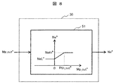
初めに、図7を用いてエンジン回転数指令作成部22を説明する。図7は、本実施例に係るエンジン回転数指令作成部の処理内容を示す制御ブロック図である。なお、図7の制御ブロック図は後述する実施例2〜4にも共通する。
First, the engine speed
エンジン回転数指令作成部22ではAcl/Rtd信号を入力としてエンジン回転数指令Ne*を作成する。図7に示す様に、Acl/Rtd信号がゼロ以下の場合、エンジン回転数はアイドル回転数NeL*に設定され、ゼロより大きくなる、つまりアクセルが踏みこまれると指定されたマップの値に従ってNeth*までエンジン回転数指令Ne*が増加する。ここで、エンジン回転数指令Ne*がNeth*になるAcl/Rtd信号をAth*とする。なお、Ath*はゼロより大きな値に設定する。
The engine speed
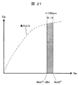
ここで、Neth*の設定方法について図9を用いて述べる。図9A及び図9Bは、本実施例に係るNeth*を決定する際の指針を示した図である。図9Aは、エンジン発電機の複合効率の構成を示す。図9Bは、エンジン(発電機)回転数とエンジン発電機出力との関係を示す。 Here, the Neth * setting method will be described with reference to FIG. FIG. 9A and FIG. 9B are diagrams showing guidelines for determining Neth * according to the present embodiment. FIG. 9A shows the combined efficiency configuration of the engine generator. FIG. 9B shows the relationship between the engine (generator) speed and the engine generator output.
Neth*はエンジン発電機の各出力に対して効率が最大となるエンジン回転数に設定される。ここで、エンジンの効率は燃料消費率として表わされる事が多く、発電機の効率は入出力効率(出力パワー/入力パワー)で表わされる事が多い。エンジン発電機の効率を考える場合、図9Aに示す様に、エンジンと発電機は同軸上で接続されているため、2つのコンポーネントの複合効率を考慮する必要がある。そこで、前記した燃料消費率と発電機効率を用いて、エンジン発電機の複合効率が最大となる回転数を算出する。まず、燃料消費率の逆数と発電機効率を同一回転数、同一出力で掛け合わせ、エンジン発電機の複合効率を算出する。次に、各発電機出力に対して最も効率の高いエンジン回転数を決定する。ここで、決定されたエンジン回転数は例えば図9Bに示す実線丸印の様になる(パターン1)。実線丸印に示す様に、最高効率となるエンジン回転数がほぼ一定になる様であれば、決定された全エンジン回転数の平均値を計算することで、Neth*を算出しても良い。また、図9Bの点線丸印(パターン2)に示す様に高出力と低出力の領域で最高効率となるエンジン回転数がずれる場合は、高出力側のみのエンジン回転数から平均値を計算することでNeth*を算出しても良い。ここで高出力側とは、例えば最大出力の1/2より大きな範囲の出力領域を示す。 Neth * is set to the engine speed that maximizes the efficiency for each output of the engine generator. Here, the efficiency of the engine is often expressed as a fuel consumption rate, and the efficiency of the generator is often expressed as input / output efficiency (output power / input power). When considering the efficiency of the engine generator, as shown in FIG. 9A, since the engine and the generator are connected on the same axis, it is necessary to consider the combined efficiency of the two components. Therefore, the rotational speed at which the combined efficiency of the engine generator is maximized is calculated using the fuel consumption rate and the generator efficiency. First, the reciprocal of the fuel consumption rate and the generator efficiency are multiplied by the same rotation speed and the same output to calculate the combined efficiency of the engine generator. Next, the most efficient engine speed is determined for each generator output. Here, the determined engine speed is, for example, a solid circle shown in FIG. 9B (pattern 1). As indicated by the solid circle, if the engine speed at which the maximum efficiency is obtained is substantially constant, Neth * may be calculated by calculating the average value of all determined engine speeds. Also, as shown by the dotted circle (pattern 2) in FIG. 9B, when the engine speed at which the maximum efficiency is shifted in the high output and low output regions, the average value is calculated from the engine speed on the high output side only. Neth * may be calculated. Here, the high output side indicates an output region in a range larger than 1/2 of the maximum output, for example.
次に、図10を用いてモータ要求出力算出部23を説明する。図10は、本実施例のモータ要求指令算出部23の処理内容を示す制御ブロック図である。
Next, the motor request
モータ要求出力算出部23では、Acl/Rtd信号と実エンジン回転数Neを入力として、2つのモードを切り替えてモータ要求出力を決定する。1つ目のモードはエンジン回転数一定出力モードである。本モードでは、前記したエンジン回転数がNeth*の値で一定となる状態でエンジン発電機の出力を変化させて制御する。その結果、エンジン発電機の高効率動作が可能となる。発電機の出力を決定するモータ要求出力値Mp1*は、Acl/Rtd信号の増加に従いMp1*が増加するように、マップを用いて算出される。マップの形状は走行性、加速性や燃費性能等により設定する。ここで、図10において設定したAth*でのモータ要求出力値Mp1*をPth*とする。
The motor request
2つ目のモードはエンジン回転数依存出力モードである。本モードでは、エンジン回転数に基づいて発電出力を制御する。このモードでは、補機系統18も考慮してエンジンの燃料消費量を低減する事を目的としている。補機系統18にはエンジン回転数増加に伴って消費パワーが増加するコンポーネント、例えばエンジンファンなどがある。そのため、エンジン回転数一定モードのみでモータ要求出力値Mp*を決める場合、設定するNeth*によっては補機系統18の消費パワー増加分が、エンジン発電機の効率改善分を相殺する可能性がある。特に低出力状態において前記した現象が顕著となるため、本モードでは実エンジン回転数Neを入力として、エンジン回転数が小さい場合にはMp2*を小さく、エンジン回転数が大きい場合にはMp2*を大きくする様にマップを設定する。さらに、実エンジン回転数Neが所定値(本実施例では、Neth*)を超えると、Mp2*を一定値(本実施例では、Pth*)に維持する。マップの形状は走行性、加速性、燃費性能およびエンジン回転数の加速性などから設定する。ここで、図10において設定したNeth*におけるモータ要求出力値Mp2*をPth*とする。前記エンジン回転数一定出力モードで設定したPth*は本モードのPth*と同一であり、Neth*と共にモードを切り替える理想的な目標値となる。ここで、Pth*は補機パワーがエンジン出力に対して大きくなるほど大きな値に設定することが望ましい。これは、エンジン発電機効率の改善分と補機パワーの増加分のトレードオフの関係があるためであり、使用機器や使用状況に合わせてPth*を設定する。その反対に、エンジン出力に対して小さな割合になるほどPth*を小さな値に設定することができる。特に補機系統18の出力がエンジン出力に対して1%以下程度の小さい影響の場合、モータ要求出力算出部内のPth*をゼロと設定し、図7に記載のAth*も極力ゼロに近い値、例えば0.01などに設定することで、エンジン回転数一定出力モードのみでモータ要求出力値Mp*を決定する事も可能である。
The second mode is an engine speed dependent output mode. In this mode, the power generation output is controlled based on the engine speed. The purpose of this mode is to reduce the fuel consumption of the engine in consideration of the
次に、図14を用いて前記した2つのモードを切り替えるモード切替部(手段又はユニット)62について説明する。図14は、本実施例のモード切替部62の処理内容を示す制御ブロック図である。図14の制御ブロック図は、実施例2、5,6においても共通する。
Next, the mode switching unit (means or unit) 62 for switching between the two modes will be described with reference to FIG. FIG. 14 is a control block diagram illustrating the processing contents of the
前記した様にモードを切り替える理想的な目標値はPth*とNeth*であり、本実施例ではNeth*を用いた切替部を説明する。モード切替部62では実エンジン回転数Neを入力(S02)し、S03においてモードの判定を行う。実エンジン回転数NeがNeth*-dNe以上の場合はエンジン回転数一定出力モード(S05)が、実エンジン回転数NeがNeth*-dNeより小さい場合はエンジン回転数依存出力モード(S04)が選択され、モード切替信号を出力(S06)する。ここで、理想的にはNeth*で切替判定を行うと良いが、実際はエンジン回転数のばらつきなどの影響によりNeth*で実エンジン回転数が一定になることは難しい。つまり、dNeは実エンジン回転数Neの外乱などによるばらつきを考慮するための許容回転数であり、エンジンの状態、使用環境に合わせて例えば100rpm以下程度に設定すると良い。よって、Neth*-dNeがモードを切り替える閾値となる。また、dNeの値はモードにより変更しても良い。例えば、エンジン回転数依存出力モードのdNeをエンジン回転数一定出力モードのdNeより小さく設定することで、ヒステリシス特性を付与し、モードの切り替えが頻繁に発生しない様にすることも可能である。
As described above, the ideal target values for switching modes are Pth * and Neth *. In this embodiment, a switching unit using Neth * will be described. The
さらに、図16を用いて発電機出力指令作成部24の説明を行う。図16は、本実施例の発電機出力指令作成部24の処理内容を示す制御ブロック図である。図16の制御ブロック図は実施例2~8においても共通する。
Furthermore, the generator output
発電機出力指令作成部24では、直流バス電圧指令値Vdc*と直流バス電圧Vdcが一致する様に発電機出力指令Gp*を出力する。入力された直流バス電圧Vdcは直流バス電圧指令Vdc*から加減算器80で減算され、PID制御81へ入力される。PID制御81の出力はリミッタ82を通り、発電機出力指令Gp*として出力される。
The generator
最後に、図18、図19、図20、図21を用いて本実施例の効果を説明する。図18は、本発明の実施例に係るエンジン回転数一定出力モードとエンジン回転数依存出力モードを使用した際のタイミングチャートを示す図である。図19は、本発明の実施例に係るエンジン回転数一定出力モードとエンジン回転数依存出力モードを使用した際の動作点軌跡を示す図である。図20は、本発明の実施例に係るエンジン回転数一定出力モードのみを使用した際のタイミングチャートを示す図である。図21は、本発明の実施例に係るエンジン回転数一定出力モードのみを使用した際の動作点軌跡を示す図である。 Finally, the effect of the present embodiment will be described with reference to FIGS. 18, 19, 20, and 21. FIG. FIG. 18 is a diagram showing a timing chart when the engine speed constant output mode and the engine speed dependent output mode according to the embodiment of the present invention are used. FIG. 19 is a diagram showing operating point trajectories when the engine speed constant output mode and the engine speed dependent output mode according to the embodiment of the present invention are used. FIG. 20 is a diagram showing a timing chart when only the constant engine speed output mode according to the embodiment of the present invention is used. FIG. 21 is a diagram showing an operating point locus when only the constant engine speed output mode according to the embodiment of the present invention is used.
図18ではダンプトラックに搭載されたエンジン発電機に対して、本実施例で示したエンジン発電機制御装置を適用した場合のタイムチャートである。はじめに、時刻Aにおいてアクセルが踏みこまれAcl/Rtd信号がAth*以上に増加すると、実エンジン回転数Neはエンジン軸のイナーシャや発電機出力の状態に応じてアイドリング回転数NeL*からNeth*まで増加する。一方、発電機出力Gpはモータ要求出力値Mp*に制御される形で増加する。時刻Bまでは実エンジン回転数NeがNeth*-dNe未満であるため、エンジン回転数依存出力モードでモータ要求出力値Mp*が決定される。一方、時刻B以降は、実エンジン回転数NeがNeth*-dNe以上になるため、エンジン回転数一定出力モードへ切り替わる。ここで、モードが切り替わる際の発電機出力はPth*-dGpである。dGpは許容エンジン回転数dNeに対応した電力変化を表す許容電力値である。エンジン回転数一定出力モードでは、Acl/Rtdに応じて出力が決定されるため、Ath*以上の踏みこみがある本例においては、Mp*がPth*以上に指令される。次に、時刻Cにおいて、Acl/Rtd信号が減少するとそれに伴い実エンジン回転数Neと発電機出力Gpが低下する。エンジン回転数NeがNeth*-dNe未満になるとエンジン回転数依存出力モードに移行するため、モータ要求出力値Mp*がエンジン回転数Neに基づいた値となる。時刻Dにおいてアクセルが再び踏みこまれると、実エンジン回転数Neおよび発電機出力Gpは増加する。最後に時刻Eにて実エンジン回転数NeがNeth*-dNe以上になると再度エンジン回転数一定出力モードへ移る。 FIG. 18 is a time chart when the engine generator control device shown in the present embodiment is applied to the engine generator mounted on the dump truck. First, the accelerator is depressed at time A Acl / When Rtd signal increases the Ath * on more than the actual engine speed Ne Neth according to the state of inertia and generator output of the engine shaft from the idling speed NeL * * Increase to. On the other hand, the generator output Gp increases while being controlled to the motor required output value Mp *. Since the actual engine speed Ne is less than Neth * -dNe until time B, the motor required output value Mp * is determined in the engine speed-dependent output mode. On the other hand, after the time B, the actual engine speed Ne becomes equal to or greater than Neth * -dNe, so the mode is switched to the constant engine speed output mode. Here, the generator output when the mode is switched is Pth * -dGp. dGp is an allowable power value representing a power change corresponding to the allowable engine speed dNe. In the engine speed constant output mode, the output is determined according to Acl / Rtd. Therefore, in this example in which the step is greater than Ath *, Mp * is commanded to be greater than Pth *. Next, at time C, when the Acl / Rtd signal decreases, the actual engine speed Ne and the generator output Gp decrease accordingly. When the engine rotational speed Ne becomes less than Neth * -dNe, the engine rotational speed dependent output mode is entered, so that the motor required output value Mp * becomes a value based on the engine rotational speed Ne. When the accelerator is depressed again at time D, the actual engine speed Ne and the generator output Gp increase. Finally, at time E, when the actual engine speed Ne becomes Neth * -dNe or more, the engine speed constant output mode is entered again.
図19は、図18の動作を横軸実エンジン回転数Ne、縦軸発電機出力Gpとして描画した動作点軌跡である。図中の一点鎖線は、エンジン発電機の最大出力を示し、ハッチングで示した範囲が動作点を示す。図が示す通り、実エンジン回転数がNth*-dNe未満(Pth*-dGp未満)ではエンジン回転数に基づいた出力特性となっており、Nth*-dNe以上(Pth*-dGp以上)ではエンジン回転数一定の出力特性なっている事が分かる。ここで、動作点軌跡が幅を持つ原因について説明する。本実施例では、モードの切り替え閾値をNeth*-dNeと設定した。エンジン回転数指令の最大値はNeth*であるため、エンジン回転数一定出力モードであっても外乱の影響によりNeth*-dNeからNeth*の間で実エンジン回転数Neは変動する。変動幅はdNeの設定値により変化するが、エンジン回転数の変動特性やエンジン発電機の効率を考慮すると、100rpmまでの値で設定すると良い。また、発電機出力Gpに関してもモータへの外乱等の影響により100W程度の変動が発生するため、動作点に幅が発生する。また、Pth*~Pth*-dGpとNeth*~Neth*-dNeで囲まれる範囲はエンジン回転数一定モードとエンジン回転数依存モードが混在する形となる。 FIG. 19 is an operating point locus in which the operation of FIG. 18 is drawn as the horizontal axis actual engine speed Ne and the vertical axis generator output Gp. The one-dot chain line in the figure indicates the maximum output of the engine generator, and the range indicated by hatching indicates the operating point. As shown in the figure, when the actual engine speed is less than Nth * -dNe (less than Pth * -dGp), the output characteristics are based on the engine speed, and for Nth * -dNe or more (Pth * -dGp or more) It can be seen that the output characteristics are constant. Here, the reason why the operating point locus has a width will be described. In this embodiment, the mode switching threshold is set to Neth * -dNe. Since the maximum value of the engine speed command is Neth *, even in the engine speed constant output mode, the actual engine speed Ne varies between Neth * -dNe and Neth * due to the influence of disturbance. The fluctuation range varies depending on the set value of dNe, but considering the fluctuation characteristics of the engine speed and the efficiency of the engine generator, it may be set at a value up to 100 rpm. Further, the generator output Gp also varies about 100 W due to the influence of disturbances to the motor, etc., so that the operating point has a width. Further, the range surrounded by Pth * to Pth * -dGp and Neth * to Neth * -dNe is a mixture of the engine speed constant mode and the engine speed dependent mode.
また、図20、図21は、Pth*をゼロ、Ath*を極力ゼロに近い値、例えば0.01に設定した場合の結果を示す。補機系統18の出力がエンジン発電機に対して影響しない程小さい場合、Pth*をゼロ、Ath*を極力ゼロに近い値、例えば0.01に設定し、エンジン回転数一定出力モードのみで発電機出力を制御する事も可能である。
20 and 21 show the results when Pth * is set to zero and Ath * is set to a value as close to zero as possible, for example, 0.01. When the output of the
図20において、はじめに時刻FでAcl/Rtd信号がAth*以上になると実エンジン回転数Neはアイドリング回転数NeL*からNeth*へ増加する。また、発電機出力については、時刻Gまでエンジン回転数依存モードであり、Pth*を0に設定しているため、発電機出力は増加しない。次に時刻Gにおいて、実エンジン回転数がNeth*-dNe以上になるとエンジン回転数一定出力モードとなり、モータ要求出力値Mp*およびGpがAcl/Rtd信号に応じて増加する。時刻HではAcl/Rtd信号が減少するがAth*を下回らないため、実エンジン回転数はNeth*を保ち、モータ要求出力値Mp* はAcl/Rtd信号に応じて減少し、発電機出力Gpも減少する。最後に時刻Iでは再度アクセルが踏みこまれ、Acl/Rtd信号が増加するため、Mp*、Gpが共に増加する。このように本実施例を用いると、エンジン発電機の高効率動作および補機系統18の消費パワーの増減を考慮してエンジン発電機を制御することが可能である。その結果、エンジンにおける燃料消費量が低減できる。
In FIG. 20, first, when the Acl / Rtd signal becomes equal to or higher than Ath * at time F, the actual engine speed Ne increases from the idling speed NeL * to Neth *. The generator output is in the engine speed dependent mode until time G, and Pth * is set to 0, so the generator output does not increase. Next, at time G, when the actual engine speed becomes equal to or greater than Neth * -dNe, the engine speed constant output mode is set, and the motor required output values Mp * and Gp increase according to the Acl / Rtd signal. At time H, the Acl / Rtd signal decreases but does not fall below Ath *, so the actual engine speed remains at Neth *, the motor required output value Mp * decreases according to the Acl / Rtd signal, and the generator output Gp also Decrease. Finally, at time I, the accelerator is depressed again, and the Acl / Rtd signal increases, so both Mp * and Gp increase. As described above, when this embodiment is used, it is possible to control the engine generator in consideration of the high-efficiency operation of the engine generator and the increase or decrease in the power consumption of the
本実施例においては、エンジン発電機の動作点を制御することでエンジン発電機を高効率に動作させ、エンジンでの燃料消費量を低減できるもうひとつのエンジン発電機制御装置およびそれを備えた鉱山向けダンプトラックについて説明する。 In the present embodiment, another engine generator control device capable of operating the engine generator with high efficiency by controlling the operating point of the engine generator and reducing fuel consumption in the engine, and a mine equipped with the same The dump truck for the vehicle will be described.
本実施例において、実施例1にて説明済みの事項に関しては説明を省略する。図1、図2、図4、図6、図7、図9、図14、図16に示すシステム構成や各種手段および、図18、図19、図20、図21のタイミングチャートおよび動作点軌跡図については、実施例1と同様である。本実施例においては、図4のモータ要求出力算出部23の構成が実施例1と異なる。図11を用いて実施例1との差分である図4のモータ要求出力算出部23を説明する。図11は、本実施例のモータ要求指令算出部(手段又はユニット)23の処理内容を示す制御ブロック図である。
In the present embodiment, description of matters already described in the first embodiment is omitted. 1, 2, 4, 6, 7, 9, 14, and 16, the timing charts and operating point trajectories in FIGS. 18, 19, 20, and 21. The diagram is the same as in the first embodiment. In the present embodiment, the configuration of the motor request
まず、実施例1との差分は一定回転数保持部(手段又はユニット)70を追加し、エンジン回転数一定出力モードのモータ要求出力値Mp1*に係数αを掛け合わせる点である。本手段では、エンジン回転数のばらつきを抑制する事が出来る。一定回転数保持部70の入力は実エンジン回転数Neであり、出力はエンジン回転数一定出力モードのモータ要求出力値Mp1*を増減させる係数αである。
First, the difference from the first embodiment is that a constant rotational speed holding unit (means or unit) 70 is added and the motor required output value Mp1 * in the engine rotational speed constant output mode is multiplied by a coefficient α. This means can suppress variations in engine speed. The input to the constant rotational
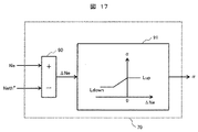
次に図17を用いて一定回転数保持部70の詳細を説明する。図17は、本実施例に係る一定回転数保持部70の処理内容を示す制御ブロック図である。なお、図17の一定回転数保持部70は実施例2,4,6,8においても共通する。
Next, details of the constant rotation
一定回転数保持部70では実エンジン回転数Neと実施例1で記載したエンジン発電機が最高効率となるエンジン回転数Neth*を入力として、Ne-Neth*を加減算器90で演算する。計算結果(差分)ΔNeは係数αを計算するマップ91に入力される。マップ91は一定回転数動作するエンジン回転数Neth*からの差であるΔNeが大きいほど大きな値をとり、ΔNeが負の大きな値になるほど小さな値を取る様に設定する。また、上限値Lup、下限値Ldownを設定しても良い。以上の様にマップの値を設定すると、実エンジン回転数NeがNeth*より大きい場合、実エンジン回転数を低減させるために、モータで使用する電力つまり発電機の出力電力を増加させる動作が可能となる。また、実エンジン回転数NeがNeth*より小さい場合には、実エンジン回転数を増加させるために、モータで使用する電力つまり発電機の出力電力を低減させる動作を行う。このように、一定回転数保持部70の出力である係数αをエンジン回転数一定出力モードに掛け合わせることで、実施例1と比較してエンジン回転数一定出力モードにおけるエンジン回転数のばらつきを抑制できると同時に、エンジン発電機の出力を最大限使用することが可能となる。
The constant rotational
本実施例においては、エンジン発電機の動作点を制御することでエンジン発電機を高効率に動作させ、エンジンでの燃料消費量を低減できるもうひとつのエンジン発電機制御装置およびそれを備えた鉱山向けダンプトラックについて説明する。 In the present embodiment, another engine generator control device capable of operating the engine generator with high efficiency by controlling the operating point of the engine generator and reducing fuel consumption in the engine, and a mine equipped with the same The dump truck for the vehicle will be described.
本実施例において、実施例1にて説明済みの事項に関しては説明を省略する。図1、図2、図6、図7、図9、図16に示すシステム構成や各種手段および、図18、図19、図20、図21のタイミングチャートおよび動作点軌跡図については、実施例1と同様である。本実施例では、実施例1との差分である図22、23、15について説明する。図15は、本実施例のモード切替部(手段又はユニット)の処理内容を示す制御ブロック図である。なお、図15のモード切替部は実施例4、7、8においても共通する。図22は、本実施例のEGUの処理内容を示す制御ブロック図である。なお、図22のEGUの処理内容を示す制御ブロック図は実施例4においても共通する。図23は、本実施例のモータ要求出力算出部(手段又はユニット)26の処理内容を示す制御ブロック図である。 In the present embodiment, description of matters already described in the first embodiment is omitted. Examples of the system configuration and various means shown in FIGS. 1, 2, 6, 7, 9, and 16, and the timing charts and operating point trajectory diagrams of FIGS. 18, 19, 20, and 21. Same as 1. In the present embodiment, FIGS. 22, 23, and 15 which are differences from the first embodiment will be described. FIG. 15 is a control block diagram showing the processing contents of the mode switching unit (means or unit) of this embodiment. The mode switching unit in FIG. 15 is common to the fourth, seventh, and eighth embodiments. FIG. 22 is a control block diagram showing the processing contents of the EGU in this embodiment. Note that the control block diagram showing the processing contents of the EGU in FIG. 22 is common to the fourth embodiment. FIG. 23 is a control block diagram showing the processing contents of the motor request output calculation unit (means or unit) 26 of the present embodiment.
図22、23、15に共通する実施例1との差分は発電機出力Gpを入力値として利用する点である。EGU14について説明した図22では、モータ要求出力算出部26の入力に発電機出力Gpが入力されている。また、モータ要求出力算出部26について説明した図23では、モード切替部64の入力に発電機出力Gpが使用されている。
The difference from the first embodiment common to FIGS. 22, 23 and 15 is that the generator output Gp is used as an input value. In FIG. 22 describing the
ここで、図15を用いてモード切替部64の詳細を説明する。実施例1と同様にモードを切り替える理想的な目標値としはPth*とNeth*があり、本実施例ではPth*を用いた切替部を説明する。本実施例のモード切替部64は、発電機出力Gpを入力(S12)として、発電機の出力モードを切り替える。S13に示す様に、発電機出力GpがPth*-dGp以上の場合はエンジン回転数一定出力モード(S15)が選択され、発電機出力GpがPth-dGpより小さい場合はエンジン回転数依存出力モード(S14)が選択され、モード切替信号を出力(S16)する。ここで、理想的にはPth*で切替判定を行うと良いが、実際はモータ出力などのばらつきにより発電機出力は変動する。つまり、dGpは発電機出力の外乱などによるばらつきを考慮するための許容電力値であり、発電機やモータ、使用環境に合わせて例えば100kW以下程度に設定すると良い。よって、Pth*-dGpがモードを切り替える閾値となる。また、dGpの値をモードにより変更しても良い。例えば、エンジン回転数依存出力モードのdGpをエンジン回転数一定出力モードのdGpより小さく設定することで、ヒステリシス特性を付与し、モードの切り替えが頻繁に発生しない様にすることも可能である。このように本実施例を用いると、実施例1と同様に補機系統18の消費パワーの増減も考慮して、エンジン発電機を高効率に動作させることが可能である
Here, the details of the
本実施例においては、エンジン発電機の動作点を制御することでエンジン発電機を高効率に動作させ、エンジンでの燃料消費量を低減できるもうひとつのエンジン発電機制御装置およびそれを備えた鉱山向けダンプトラックについて説明する。 In the present embodiment, another engine generator control device capable of operating the engine generator with high efficiency by controlling the operating point of the engine generator and reducing fuel consumption in the engine, and a mine equipped with the same The dump truck for the vehicle will be described.
本実施例において、実施例1、2,3にて説明済みの事項に関しては説明を省略する。図1、図2、図22、図6、図7、図9、図15、図16、図17に示すシステム構成や各種手段および、図18、図19、図20、図21のタイミングチャートおよび動作点軌跡図については、実施例1、2、3と同様である。本実施例について、実施例3を基準にしてその違いを説明する。図24は、本実施例のモータ要求指令算出部26の処理内容を示す制御ブロック図である。実施例3との差異は、図24に示す様に一定回転数保持部70を追加し、エンジン回転数一定出力モードのモータ要求出力値Mp1*に係数αを掛け合わせる点である。一定回転数保持部70については、図17に示す通りであり、実施例2にて説明済みである。このように、一定回転数保持部70の出力である係数αをエンジン回転数一定出力モードに掛け合わせることで、実施例3と比較してエンジン回転数一定出力モードにおけるエンジン回転数のばらつきを抑制できると同時に、エンジン発電機の出力を最大限使用することが可能となる。
In the present embodiment, description of matters already described in the first, second, and third embodiments is omitted. 1, FIG. 2, FIG. 22, FIG. 6, FIG. 7, FIG. 9, FIG. 15, FIG. 16, FIG. 17, the system configurations and various means shown in FIG. The operating point locus diagram is the same as in the first, second, and third embodiments. The difference between the present embodiment and the third embodiment will be described. FIG. 24 is a control block diagram showing the processing contents of the motor request
本実施例においては、エンジン発電機の動作点を制御することでエンジン発電機を高効率に動作させ、エンジンでの燃料消費量を低減できるもうひとつのエンジン発電機制御装置およびそれを備えた鉱山向けダンプトラックについて説明する。 In the present embodiment, another engine generator control device capable of operating the engine generator with high efficiency by controlling the operating point of the engine generator and reducing fuel consumption in the engine, and a mine equipped with the same The dump truck for the vehicle will be described.
本実施例において、実施例1にて説明済みの事項に関しては説明を省略する。図1、図6、図9、図14、図16に示すシステム構成や各種手段は実施例1と同様である。実施例1との差分を図3,図5、図8、図12を用いて説明する。図3はエンジン発電機と制御装置を搭載したダンプトラックのシステムブロック図であり、本実施例では運行管理システムや無人走行システムなどから送信されるモータ要求出力値Mp_out*を受信する無線および有線受信端末17からの情報を入力としてEGU18の処理を行う。図5にEGU18の詳細を示す。図5の内、実施例1との差分はエンジン回転数指令作成部(手段又はユニット)30とモータ要求出力算出部(手段又はユニット)31である。
In the present embodiment, description of matters already described in the first embodiment is omitted. The system configuration and various means shown in FIGS. 1, 6, 9, 14, and 16 are the same as those in the first embodiment. Differences from the first embodiment will be described with reference to FIGS. 3, 5, 8, and 12. FIG. 3 is a system block diagram of a dump truck equipped with an engine generator and a control device. In this embodiment, wireless and wired reception for receiving a motor request output value Mp_out * transmitted from an operation management system, an unmanned traveling system, or the like. The
まず、エンジン回転数指令作成部30の詳細を図8で説明する。図8は、本実施例のエンジン回転数指令作成部30の処理内容を示す制御ブロック図である。なお、図8のエンジン回転数指令作成部30の処理内容を示す制御ブロック図は実施例6~8においても共通である。エンジン回転数指令作成部30では無線および有線受信端末17で受信したモータ要求出力値Mp_out*を入力として、エンジン回転数指令Ne*をマップ51により作成する。マップはモータ要求出力値Mp_out*がゼロ以下の場合、エンジン回転数をアイドル回転数NeL*に設定し、モータ要求出力値Mp_out*ゼロより大きくなるとエンジン回転数指令Ne*をNeth*まで増加させる。ここで、エンジン回転数指令Ne*がNeth*になるMp*をPth_out*とする。なお、Pth_out*はゼロより大きな値に設定する。ここで、Neth*の設定方法は実施例1で述べた通りである。
First, details of the engine speed
次に、モータ要求出力算出部31の詳細を図12で説明する。図12は、本実施例のモータ要求出力算出部31の処理内容を示す制御ブロック図である。
Next, details of the motor request
実施例1との差分は、エンジン回転数一定出力モードにおけるモータ要求出力値Mp*の算出方法である。図が示す通り、エンジン回転数一定出力モードが選択された際には入力であるMp_out*をそのままモータ要求出力値Mp*として使用する。また、補機系統18の出力がエンジン出力に対して1%以下程度の小さい影響の場合、モータ要求出力算出部31内のPth*をゼロに設定し、図8に記載のPth_out*を極力ゼロに近い値、例えば0.01などに設定することで、エンジン回転数一定出力モードのみでモータ要求出力値Mp*を決定する事も可能である。また、図18、図19、図20、図21のタイミングチャートおよび動作点軌跡図については、EGU18の入力がモータ要求出力Mp_out*になることから、実施例1と比較して、Acl/Rtd信号がMp_out*に置き換わり、Ath*がPth_out*に置き換わる事になる。Acl/Rtd信号とMp_out*信号がAth*,Pth_out*に対して相対的に同じ動きをする場合、実施例1で説明した動作と本実施例の動作は同様になる。このように、モータ要求出力値Mp_out*を直接入力できる構成を取ることで、例えば、無人走行可能なダンプトラックにおいてもエンジンの燃料消費量を低減することが可能となる。
The difference from the first embodiment is a calculation method of the motor required output value Mp * in the engine speed constant output mode. As shown in the figure, when the engine speed constant output mode is selected, the input Mp_out * is used as it is as the motor required output value Mp *. Further, when the output of the
本実施例においては、エンジン発電機の動作点を制御することでエンジン発電機を高効率に動作させ、エンジンでの燃料消費量を低減できるもうひとつのエンジン発電機制御装置およびそれを備えた鉱山向けダンプトラックについて説明する。 In the present embodiment, another engine generator control device capable of operating the engine generator with high efficiency by controlling the operating point of the engine generator and reducing fuel consumption in the engine, and a mine equipped with the same The dump truck for the vehicle will be described.
本実施例において、実施例1、2、5にて説明済みの事項に関しては説明を省略する。図1、図3、図5、図6、図8、図9、図14、図16、図17に示すシステム構成や各種手段および、図18、図19、図20、図21のタイミングチャートおよび動作点軌跡図については、実施例1,2,5と同様である。本実施例では実施例5を基準にしてその違いを説明する。図13は、本実施例のモータ要求指令算出部31の処理内容を示す制御ブロック図である。
In the present embodiment, description of matters already described in
実施例5との差分は、図13に示す様に一定回転数保持部(手段又はユニット)70を追加し、エンジン回転数一定出力モードのモータ要求出力値Mp_out*に係数αを掛け合わせる点である。一定回転数保持部70に関する説明は実施例2にて説明済みである。このように、一定回転数保持部70の出力である係数αをエンジン回転数一定出力モードに掛け合わせることで、実施例5と比較してエンジン回転数一定出力モードにおけるエンジン回転数のばらつきを抑制できると同時に、エンジン発電機の出力を最大限使用することが可能となる。
The difference from the fifth embodiment is that a constant rotational speed holding unit (means or unit) 70 is added as shown in FIG. 13 and the motor required output value Mp_out * in the constant engine rotational speed output mode is multiplied by a coefficient α. It is. The description regarding the constant rotation
本実施例においては、エンジン発電機の動作点を制御することでエンジン発電機を高効率に動作させ、エンジンでの燃料消費量を低減できるもうひとつのエンジン発電機制御装置およびそれを備えた鉱山向けダンプトラックについて説明する。 In the present embodiment, another engine generator control device capable of operating the engine generator with high efficiency by controlling the operating point of the engine generator and reducing fuel consumption in the engine, and a mine equipped with the same The dump truck for the vehicle will be described.
本実施例において、実施例1,2,3,5,6にて説明済みの事項に関しては説明を省略する。図1、図3、図6、図8、図9、図15、図16に示すシステム構成や各種手段および、図18、図19、図20、図21のタイミングチャートおよび動作点軌跡図については、実施例1,2,3,5,6と同様である。本実施例は図25、図26、図15を用いて、実施例5を基準にその違いを説明する。図15は実施例3と共通である。図25は、本実施例のEGUの処理内容を示す制御ブロック図である。なお、図25のEGUの処理内容を示す制御ブロック図は実施例8でも共通である。図26は、本実施例のモータ要求出力算出部(手段又はユニット)32の処理内容を示す制御ブロック図である。 In the present embodiment, description of matters already described in the first, second, third, fifth, and sixth embodiments is omitted. 1, 3, 6, 8, 9, 15, and 16, and the timing charts and operating point locus diagrams of FIGS. 18, 19, 20, and 21. The same as in Examples 1, 2, 3, 5, and 6. This embodiment will be described with reference to FIG. 25, FIG. 26, and FIG. FIG. 15 is common to the third embodiment. FIG. 25 is a control block diagram showing the processing contents of the EGU in this embodiment. The control block diagram showing the processing contents of the EGU in FIG. 25 is common to the eighth embodiment. FIG. 26 is a control block diagram illustrating the processing contents of the motor request output calculation unit (means or unit) 32 of the present embodiment.
図25、26、15に共通する実施例5との差分は発電機出力Gpを入力値として利用する点である。EGU18について説明した図25では、モータ要求出力算出部32の入力に発電機出力Gpが入力されている。また、モータ要求出力算出部32について説明した図26では、モード切替部64の入力に発電機出力Gpが使用されている。モード切替部64を示す図15については、実施例3にて説明済みである。このように本実施例を用いると、実施例5と同様に補機系統18の消費パワーの増減も考慮して、エンジン発電機を高効率に動作させることが可能である
The difference from the fifth embodiment common to FIGS. 25, 26 and 15 is that the generator output Gp is used as an input value. In FIG. 25 describing the
本実施例においては、エンジン発電機の動作点を制御することでエンジン発電機を高効率に動作させ、エンジンでの燃料消費量を低減できるもうひとつのエンジン発電機制御装置およびそれを備えた鉱山向けダンプトラックについて説明する。 In the present embodiment, another engine generator control device capable of operating the engine generator with high efficiency by controlling the operating point of the engine generator and reducing fuel consumption in the engine, and a mine equipped with the same The dump truck for the vehicle will be described.
本実施例において、実施例1~7にて説明済みの事項に関しては説明を省略する。図1、図3、図25、図6、図8、図9、図15、図16、図17に示すシステム構成や各種手段および、図18、図19、図20、図21のタイミングチャートおよび動作点軌跡図については、実施例1~7と同様である。本実施例では実施例7を基準にしてその違いを説明する。図27は、本実施例のモータ要求出力算出部32の処理内容を示す制御ブロック図である。
In the present embodiment, description of matters already described in the first to seventh embodiments is omitted. 1, FIG. 3, FIG. 25, FIG. 6, FIG. 8, FIG. 9, FIG. 15, FIG. 16, FIG. The operating point locus diagram is the same as in the first to seventh embodiments. In the present embodiment, the difference will be described with reference to the seventh embodiment. FIG. 27 is a control block diagram illustrating the processing contents of the motor request
実施例7との差分は、図27に示す様に一定回転数保持部70を追加し、エンジン回転数一定出力モードのモータ要求出力値Mp_out*に係数αを掛け合わせる点である。一定回転数保持部70については、図17に示す通りであり、実施例2にて説明済みである。このように、一定回転数保持部70の出力である係数αをエンジン回転数一定出力モードに掛け合わせることで、実施例7と比較してエンジン回転数一定出力モードにおけるエンジン回転数のばらつきを抑制できると同時に、エンジン発電機の出力を最大限使用することが可能となる。
The difference from the seventh embodiment is that a constant rotational
なお、本発明は上記した各実施例に限定されるものではなく、様々な変形例が含まれる。例えば、上記した実施例は本発明を分かりやすく説明するために詳細に説明したものであり、必ずしも全ての構成を備えるものに限定されるものではない。また、ある実施例の構成の一部を他の実施例の構成に置き換えることが可能であり、また、ある実施例の構成に他の実施例の構成を加えることも可能である。また、各実施例の構成の一部について、他の構成の追加・削除・置換をすることが可能である。 In addition, this invention is not limited to each above-mentioned Example, Various modifications are included. For example, the above-described embodiments have been described in detail for easy understanding of the present invention, and are not necessarily limited to those having all the configurations. Further, a part of the configuration of one embodiment can be replaced with the configuration of another embodiment, and the configuration of another embodiment can be added to the configuration of one embodiment. Further, it is possible to add, delete, and replace other configurations for a part of the configuration of each embodiment.
1L,1R…走行用モータ、2…発電機、3L,3R…インバータ、4…エンジン、9a…抵抗器、9b…チョッパ、11…ECU、12…GMU、13…MCU、14,18…EGU、15…アクセルペダル、16…リタードペダル、17…無人走行システム、22,30…エンジン回転数指令作成部(手段又はユニット)、23,26,31,32…モータ要求出力算出部(手段又はユニット)、24…発電機出力指令作成部(手段又はユニット)、70…一定回転数保持部(手段又はユニット)、62,64…モード切替部(手段又はユニット)。
1L, 1R ... Traveling motor, 2 ... Generator, 3L, 3R ... Inverter, 4 ... Engine, 9a ... Resistor, 9b ... Chopper, 11 ... ECU, 12 ... GMU, 13 ... MCU, 14, 18 ... EGU, DESCRIPTION OF
Claims (8)
発電量閾値以上の発電機出力又は実際のエンジン回転数が回転数閾値以上では、エンジン回転数を一定として、前記発電機の出力を変化させる出力指令値を出力し、
前記一定となるエンジン回転数は、前記エンジンの燃料消費率の逆数と前記発電機の入出力効率とを同一回転数と同一出力において乗算した複合効率が各発電機出力において最大となるエンジン回転数の平均値であることを特徴とするエンジン発電機制御装置。 In an engine generator control device comprising an engine, a generator driven by the engine, and a control device for controlling the engine and the generator,
Power generation threshold value or the generator output or the actual engine speed is in the above rotational speed threshold, then the engine speed is constant, and outputs the output command value to vary the output of the generator,
The constant engine speed is the engine speed at which the combined efficiency obtained by multiplying the reciprocal of the fuel consumption rate of the engine and the input / output efficiency of the generator at the same speed and the same output is the maximum at each generator output. engine generator controller, wherein the average der Rukoto of.
前記発電機の出力は、前記一定となるエンジン回転数より実際のエンジン回転数が低下すると低下し、前記一定となるエンジン回転数より実際のエンジン回転数が増加すると増加することを特徴とするエンジン発電機制御装置。 In claim 1 ,
The output of the generator decreases when the actual engine speed decreases from the constant engine speed, and increases when the actual engine speed increases from the constant engine speed. Generator control device.
前記発電機の出力電力により駆動されるモータを備え、
前記発電機の出力は前記モータの出力要求値により決定されることを特徴とするエンジン発電機制御装置。 The engine generator control device according to claim 2 ,
Comprising a motor driven by the output power of the generator;
The engine generator control device according to claim 1, wherein an output of the generator is determined by a required output value of the motor.
前記エンジン回転数を一定とし前記発電機の出力を変化させて制御するエンジン回転数一定出力モードと、前記エンジン回転数の増加に基づいて前記発電機の出力が増加するエンジン回転数依存出力モードと、前記エンジン回転数一定出力モードと前記エンジン回転数依存出力モードとを切り替えるモード切替部とを有し、
前記モード切替部は、前記発電機出力が発電量閾値未満又は前記実際のエンジン回転数が回転数閾値未満の場合に前記エンジン回転数依存出力モードに切り替え、前記発電機出力が発電量閾値以上又は前記実際のエンジン回転数が回転数閾値以上となった場合に前記エンジン回転数一定出力モードに切り替えることを特徴とするエンジン発電機制御装置。 The engine generator control device according to claim 1,
An engine speed constant output mode in which the engine speed is constant and the output of the generator is changed and controlled, and an engine speed dependent output mode in which the output of the generator increases based on an increase in the engine speed And a mode switching unit that switches between the engine speed constant output mode and the engine speed dependent output mode,
The mode switching unit switches to the engine speed dependent output mode when the generator output is less than a power generation amount threshold or the actual engine speed is less than the rotation speed threshold, and the generator output is equal to or greater than the power generation threshold. The engine generator control device according to claim 1, wherein the engine generator control mode is switched to the constant engine speed output mode when the actual engine speed becomes equal to or greater than a speed threshold value.
前記モード切替部は、前記一定となるエンジン回転数から実エンジン回転数のばらつきを許容する許容回転数を減算した値を前記エンジン回転数の前記回転数閾値として用いることを特徴とするエンジン発電機制御装置。 The engine generator control device according to claim 4 ,
The mode switching unit uses a value obtained by subtracting a permissible engine speed allowing variation in actual engine speed from the constant engine speed as the engine speed threshold value. Control device.
前記モード切替部は、目標とするモード切替発電機出力から発電機出力のばらつきを許容する許容出力値を減算した値を前記発電機出力の前記発電量閾値として用いることを特徴とするエンジン発電機制御装置。 The engine generator control device according to claim 4 ,
The mode switching unit uses a value obtained by subtracting an allowable output value allowing variation in generator output from a target mode switching generator output as the power generation amount threshold value of the generator output. Control device.
前記発電機の出力電力により駆動されるモータを備え、
前記発電機の出力は前記モータの出力要求により決定されることを特徴とするエンジン発電機制御装置。 In the engine generator control device according to claim 5 or 6 ,
Comprising a motor driven by the output power of the generator;
The engine generator control device according to claim 1, wherein the output of the generator is determined by an output request of the motor.
請求項1乃至7のいずれか1項に記載したエンジン発電機制御装置を備えたことを特徴とする鉱山向けダンプトラック。 In a dump truck for a mine equipped with a loading platform on the vehicle body, and a pair of left and right driven wheels and a pair of left and right drive wheels driven by a motor,
A dump truck for a mine comprising the engine generator control device according to any one of claims 1 to 7 .
Priority Applications (1)
| Application Number | Priority Date | Filing Date | Title |
|---|---|---|---|
| JP2014219114A JP6438273B2 (en) | 2014-10-28 | 2014-10-28 | Engine generator control device and mining dump truck equipped with the same |
Applications Claiming Priority (1)
| Application Number | Priority Date | Filing Date | Title |
|---|---|---|---|
| JP2014219114A JP6438273B2 (en) | 2014-10-28 | 2014-10-28 | Engine generator control device and mining dump truck equipped with the same |
Publications (3)
| Publication Number | Publication Date |
|---|---|
| JP2016086580A JP2016086580A (en) | 2016-05-19 |
| JP2016086580A5 JP2016086580A5 (en) | 2017-09-14 |
| JP6438273B2 true JP6438273B2 (en) | 2018-12-12 |
Family
ID=55972531
Family Applications (1)
| Application Number | Title | Priority Date | Filing Date |
|---|---|---|---|
| JP2014219114A Expired - Fee Related JP6438273B2 (en) | 2014-10-28 | 2014-10-28 | Engine generator control device and mining dump truck equipped with the same |
Country Status (1)
| Country | Link |
|---|---|
| JP (1) | JP6438273B2 (en) |
Families Citing this family (1)
| Publication number | Priority date | Publication date | Assignee | Title |
|---|---|---|---|---|
| JP6909694B2 (en) * | 2017-09-29 | 2021-07-28 | 日立建機株式会社 | Work vehicle power regeneration system |
Family Cites Families (8)
| Publication number | Priority date | Publication date | Assignee | Title |
|---|---|---|---|---|
| JPH09200907A (en) * | 1996-01-19 | 1997-07-31 | Toyota Motor Corp | Hybrid electric motorcar |
| JP3292130B2 (en) * | 1998-03-06 | 2002-06-17 | 三菱自動車工業株式会社 | Series hybrid electric vehicle |
| JP4111629B2 (en) * | 1999-04-09 | 2008-07-02 | 株式会社小松製作所 | Hybrid dump truck |
| JP4814202B2 (en) * | 2007-11-22 | 2011-11-16 | 日立建機株式会社 | Electric drive truck drive system |
| WO2010002051A1 (en) * | 2008-07-04 | 2010-01-07 | Seoul National University Industry Foundation | Engine-generator provided with super capacitor |
| JP2010173390A (en) * | 2009-01-28 | 2010-08-12 | Nissan Motor Co Ltd | Controller for vehicle |
| JP5751764B2 (en) * | 2010-06-30 | 2015-07-22 | 三菱重工マシナリーテクノロジー株式会社 | Crane control device and crane device |
| US9475484B2 (en) * | 2013-03-29 | 2016-10-25 | Hitachi Construction Machinery Co., Ltd. | Engine rotation control system |
-
2014
- 2014-10-28 JP JP2014219114A patent/JP6438273B2/en not_active Expired - Fee Related
Also Published As
| Publication number | Publication date |
|---|---|
| JP2016086580A (en) | 2016-05-19 |
Similar Documents
| Publication | Publication Date | Title |
|---|---|---|
| JP4876429B2 (en) | Vehicle drive control device | |
| JP6330820B2 (en) | Electric vehicle control device and electric vehicle control method | |
| US20130006456A1 (en) | Systems and methods for engine load management for electric drive vehicles | |
| JP5447346B2 (en) | Control device for hybrid electric vehicle | |
| JP3852400B2 (en) | Vehicle control device | |
| KR102120290B1 (en) | Control device for electric vehicle and control method for electric vehicle | |
| US7605552B2 (en) | Control apparatus for electric vehicles | |
| US5677610A (en) | Control apparatus for electric vehicles | |
| KR20170140355A (en) | Control device of electric vehicle and control method of electric vehicle | |
| US10486680B2 (en) | Hybrid vehicle | |
| CN109130882B (en) | Freight car and method for controlling driving motor for traveling mounted on freight car | |
| JP2010132154A (en) | Vehicle | |
| JP7449109B2 (en) | Vehicle control device | |
| JP6589554B2 (en) | Control method and control apparatus for electric vehicle | |
| JP2008162563A (en) | Constant speed travel controller of hybrid vehicle | |
| JP7056219B2 (en) | Motor vehicle control method and motor vehicle control device | |
| JP6438273B2 (en) | Engine generator control device and mining dump truck equipped with the same | |
| US6795755B2 (en) | Method for operating a load-dependent power-generating system in a vehicle | |
| JP2010268639A (en) | Vehicle controller | |
| JP6064727B2 (en) | Control device for each wheel independent drive cart | |
| JPH08308016A (en) | Generator for hybrid vehicle | |
| JP5496294B2 (en) | Vehicle resonance suppression control device | |
| JP5364605B2 (en) | Railway vehicle drive system | |
| JP2006050866A (en) | Controller of motor for vehicle | |
| JP6570769B2 (en) | Propulsion control device |
Legal Events
| Date | Code | Title | Description |
|---|---|---|---|
| A521 | Request for written amendment filed |
Free format text: JAPANESE INTERMEDIATE CODE: A523 Effective date: 20170802 |
|
| A621 | Written request for application examination |
Free format text: JAPANESE INTERMEDIATE CODE: A621 Effective date: 20170802 |
|
| A131 | Notification of reasons for refusal |
Free format text: JAPANESE INTERMEDIATE CODE: A131 Effective date: 20180424 |
|
| A977 | Report on retrieval |
Free format text: JAPANESE INTERMEDIATE CODE: A971007 Effective date: 20180427 |
|
| A521 | Request for written amendment filed |
Free format text: JAPANESE INTERMEDIATE CODE: A523 Effective date: 20180620 |
|
| TRDD | Decision of grant or rejection written | ||
| A01 | Written decision to grant a patent or to grant a registration (utility model) |
Free format text: JAPANESE INTERMEDIATE CODE: A01 Effective date: 20181113 |
|
| A61 | First payment of annual fees (during grant procedure) |
Free format text: JAPANESE INTERMEDIATE CODE: A61 Effective date: 20181116 |
|
| R150 | Certificate of patent or registration of utility model |
Ref document number: 6438273 Country of ref document: JP Free format text: JAPANESE INTERMEDIATE CODE: R150 |
|
| LAPS | Cancellation because of no payment of annual fees |