WO2012008219A1 - Electric work vehicle - Google Patents
Electric work vehicle Download PDFInfo
- Publication number
- WO2012008219A1 WO2012008219A1 PCT/JP2011/061525 JP2011061525W WO2012008219A1 WO 2012008219 A1 WO2012008219 A1 WO 2012008219A1 JP 2011061525 W JP2011061525 W JP 2011061525W WO 2012008219 A1 WO2012008219 A1 WO 2012008219A1
- Authority
- WO
- WIPO (PCT)
- Prior art keywords
- resistor
- mode
- blower
- power
- heat generation
- Prior art date
Links
Images


Classifications
-
- B—PERFORMING OPERATIONS; TRANSPORTING
- B60—VEHICLES IN GENERAL
- B60K—ARRANGEMENT OR MOUNTING OF PROPULSION UNITS OR OF TRANSMISSIONS IN VEHICLES; ARRANGEMENT OR MOUNTING OF PLURAL DIVERSE PRIME-MOVERS IN VEHICLES; AUXILIARY DRIVES FOR VEHICLES; INSTRUMENTATION OR DASHBOARDS FOR VEHICLES; ARRANGEMENTS IN CONNECTION WITH COOLING, AIR INTAKE, GAS EXHAUST OR FUEL SUPPLY OF PROPULSION UNITS IN VEHICLES
- B60K11/00—Arrangement in connection with cooling of propulsion units
-
- B—PERFORMING OPERATIONS; TRANSPORTING
- B60—VEHICLES IN GENERAL
- B60K—ARRANGEMENT OR MOUNTING OF PROPULSION UNITS OR OF TRANSMISSIONS IN VEHICLES; ARRANGEMENT OR MOUNTING OF PLURAL DIVERSE PRIME-MOVERS IN VEHICLES; AUXILIARY DRIVES FOR VEHICLES; INSTRUMENTATION OR DASHBOARDS FOR VEHICLES; ARRANGEMENTS IN CONNECTION WITH COOLING, AIR INTAKE, GAS EXHAUST OR FUEL SUPPLY OF PROPULSION UNITS IN VEHICLES
- B60K1/00—Arrangement or mounting of electrical propulsion units
-
- B—PERFORMING OPERATIONS; TRANSPORTING
- B60—VEHICLES IN GENERAL
- B60L—PROPULSION OF ELECTRICALLY-PROPELLED VEHICLES; SUPPLYING ELECTRIC POWER FOR AUXILIARY EQUIPMENT OF ELECTRICALLY-PROPELLED VEHICLES; ELECTRODYNAMIC BRAKE SYSTEMS FOR VEHICLES IN GENERAL; MAGNETIC SUSPENSION OR LEVITATION FOR VEHICLES; MONITORING OPERATING VARIABLES OF ELECTRICALLY-PROPELLED VEHICLES; ELECTRIC SAFETY DEVICES FOR ELECTRICALLY-PROPELLED VEHICLES
- B60L50/00—Electric propulsion with power supplied within the vehicle
- B60L50/10—Electric propulsion with power supplied within the vehicle using propulsion power supplied by engine-driven generators, e.g. generators driven by combustion engines
- B60L50/13—Electric propulsion with power supplied within the vehicle using propulsion power supplied by engine-driven generators, e.g. generators driven by combustion engines using AC generators and AC motors
-
- B—PERFORMING OPERATIONS; TRANSPORTING
- B60—VEHICLES IN GENERAL
- B60L—PROPULSION OF ELECTRICALLY-PROPELLED VEHICLES; SUPPLYING ELECTRIC POWER FOR AUXILIARY EQUIPMENT OF ELECTRICALLY-PROPELLED VEHICLES; ELECTRODYNAMIC BRAKE SYSTEMS FOR VEHICLES IN GENERAL; MAGNETIC SUSPENSION OR LEVITATION FOR VEHICLES; MONITORING OPERATING VARIABLES OF ELECTRICALLY-PROPELLED VEHICLES; ELECTRIC SAFETY DEVICES FOR ELECTRICALLY-PROPELLED VEHICLES
- B60L7/00—Electrodynamic brake systems for vehicles in general
- B60L7/02—Dynamic electric resistor braking
- B60L7/06—Dynamic electric resistor braking for vehicles propelled by ac motors
-
- B—PERFORMING OPERATIONS; TRANSPORTING
- B60—VEHICLES IN GENERAL
- B60L—PROPULSION OF ELECTRICALLY-PROPELLED VEHICLES; SUPPLYING ELECTRIC POWER FOR AUXILIARY EQUIPMENT OF ELECTRICALLY-PROPELLED VEHICLES; ELECTRODYNAMIC BRAKE SYSTEMS FOR VEHICLES IN GENERAL; MAGNETIC SUSPENSION OR LEVITATION FOR VEHICLES; MONITORING OPERATING VARIABLES OF ELECTRICALLY-PROPELLED VEHICLES; ELECTRIC SAFETY DEVICES FOR ELECTRICALLY-PROPELLED VEHICLES
- B60L7/00—Electrodynamic brake systems for vehicles in general
- B60L7/22—Dynamic electric resistor braking, combined with dynamic electric regenerative braking
-
- B—PERFORMING OPERATIONS; TRANSPORTING
- B60—VEHICLES IN GENERAL
- B60L—PROPULSION OF ELECTRICALLY-PROPELLED VEHICLES; SUPPLYING ELECTRIC POWER FOR AUXILIARY EQUIPMENT OF ELECTRICALLY-PROPELLED VEHICLES; ELECTRODYNAMIC BRAKE SYSTEMS FOR VEHICLES IN GENERAL; MAGNETIC SUSPENSION OR LEVITATION FOR VEHICLES; MONITORING OPERATING VARIABLES OF ELECTRICALLY-PROPELLED VEHICLES; ELECTRIC SAFETY DEVICES FOR ELECTRICALLY-PROPELLED VEHICLES
- B60L2200/00—Type of vehicles
- B60L2200/40—Working vehicles
-
- B—PERFORMING OPERATIONS; TRANSPORTING
- B60—VEHICLES IN GENERAL
- B60L—PROPULSION OF ELECTRICALLY-PROPELLED VEHICLES; SUPPLYING ELECTRIC POWER FOR AUXILIARY EQUIPMENT OF ELECTRICALLY-PROPELLED VEHICLES; ELECTRODYNAMIC BRAKE SYSTEMS FOR VEHICLES IN GENERAL; MAGNETIC SUSPENSION OR LEVITATION FOR VEHICLES; MONITORING OPERATING VARIABLES OF ELECTRICALLY-PROPELLED VEHICLES; ELECTRIC SAFETY DEVICES FOR ELECTRICALLY-PROPELLED VEHICLES
- B60L2250/00—Driver interactions
-
- Y—GENERAL TAGGING OF NEW TECHNOLOGICAL DEVELOPMENTS; GENERAL TAGGING OF CROSS-SECTIONAL TECHNOLOGIES SPANNING OVER SEVERAL SECTIONS OF THE IPC; TECHNICAL SUBJECTS COVERED BY FORMER USPC CROSS-REFERENCE ART COLLECTIONS [XRACs] AND DIGESTS
- Y02—TECHNOLOGIES OR APPLICATIONS FOR MITIGATION OR ADAPTATION AGAINST CLIMATE CHANGE
- Y02T—CLIMATE CHANGE MITIGATION TECHNOLOGIES RELATED TO TRANSPORTATION
- Y02T10/00—Road transport of goods or passengers
- Y02T10/60—Other road transportation technologies with climate change mitigation effect
- Y02T10/64—Electric machine technologies in electromobility
-
- Y—GENERAL TAGGING OF NEW TECHNOLOGICAL DEVELOPMENTS; GENERAL TAGGING OF CROSS-SECTIONAL TECHNOLOGIES SPANNING OVER SEVERAL SECTIONS OF THE IPC; TECHNICAL SUBJECTS COVERED BY FORMER USPC CROSS-REFERENCE ART COLLECTIONS [XRACs] AND DIGESTS
- Y02—TECHNOLOGIES OR APPLICATIONS FOR MITIGATION OR ADAPTATION AGAINST CLIMATE CHANGE
- Y02T—CLIMATE CHANGE MITIGATION TECHNOLOGIES RELATED TO TRANSPORTATION
- Y02T10/00—Road transport of goods or passengers
- Y02T10/60—Other road transportation technologies with climate change mitigation effect
- Y02T10/70—Energy storage systems for electromobility, e.g. batteries
-
- Y—GENERAL TAGGING OF NEW TECHNOLOGICAL DEVELOPMENTS; GENERAL TAGGING OF CROSS-SECTIONAL TECHNOLOGIES SPANNING OVER SEVERAL SECTIONS OF THE IPC; TECHNICAL SUBJECTS COVERED BY FORMER USPC CROSS-REFERENCE ART COLLECTIONS [XRACs] AND DIGESTS
- Y02—TECHNOLOGIES OR APPLICATIONS FOR MITIGATION OR ADAPTATION AGAINST CLIMATE CHANGE
- Y02T—CLIMATE CHANGE MITIGATION TECHNOLOGIES RELATED TO TRANSPORTATION
- Y02T10/00—Road transport of goods or passengers
- Y02T10/60—Other road transportation technologies with climate change mitigation effect
- Y02T10/7072—Electromobility specific charging systems or methods for batteries, ultracapacitors, supercapacitors or double-layer capacitors
-
- Y—GENERAL TAGGING OF NEW TECHNOLOGICAL DEVELOPMENTS; GENERAL TAGGING OF CROSS-SECTIONAL TECHNOLOGIES SPANNING OVER SEVERAL SECTIONS OF THE IPC; TECHNICAL SUBJECTS COVERED BY FORMER USPC CROSS-REFERENCE ART COLLECTIONS [XRACs] AND DIGESTS
- Y10—TECHNICAL SUBJECTS COVERED BY FORMER USPC
- Y10S—TECHNICAL SUBJECTS COVERED BY FORMER USPC CROSS-REFERENCE ART COLLECTIONS [XRACs] AND DIGESTS
- Y10S903/00—Hybrid electric vehicles, HEVS
- Y10S903/902—Prime movers comprising electrical and internal combustion motors
Definitions
- the present invention relates to an electric work vehicle suitable for use in, for example, a dump truck.
- an electric work vehicle that employs an electric drive system as a driving system for traveling, such as a large dump truck, is known.
- Such an electric work vehicle includes an electric motor attached to the vehicle body, a DC power source such as a battery, and an inverter provided between the electric motor.
- a DC power source such as a battery
- an inverter provided between the electric motor.
- an inverter is provided with a resistor connected thereto, and a blower for supplying cooling air to the resistor is known (Patent Document). 1, Patent Document 2).
- the resistor may freeze, for example, when it is cold, and on the other hand, the resistor may be wetted by rain water or the like when it rains. In this case, the insulation between the resistor circuit and the vehicle body frame is lowered, and the circuit may be short-circuited to the ground.
- a configuration in which heat generation by a resistor and air blowing by a blower are performed simultaneously can be considered. According to this configuration, in addition to melting ice or evaporating moisture due to the heat generated by the resistor, the resistor can be dried by blowing air from the blower, thereby eliminating the factor of lowering insulation.
- the present invention has been made in view of the above-described problems of the prior art, and an object of the present invention is to arbitrarily select heat generated by the resistor and air blown by the blower according to the state of the resistor, the state of the outside air, and the like.
- An object of the present invention is to provide an electric work vehicle that can be used.
- an electric work vehicle converts an electric motor for driving driving provided in a vehicle body and DC power from a DC power source provided in the vehicle body into AC power of variable frequency.
- a bidirectional converter that drives the electric motor and converts the output of AC power from the electric motor into DC power, and the electromotive force that is provided in the vehicle body and regenerated by the electric motor is consumed.
- the operator can select an appropriate mode from the three modes that can be selected by the mode selection switch in accordance with the state of the resistor and the state of the outside air.
- a heat generation mode in which only heat generation is performed can be selected, and surrounding moisture can be evaporated by heat generation of the resistor while preventing blowing of snowstorm or the like.
- water collected around the resistor, it is possible to select an air blowing mode in which only air is blown to blow away the accumulated water.
- a heating air blowing mode in which heat generation and air blowing are performed together can be selected, and the resistor can be dried while melting the ice of the resistor.
- the mode according to the condition of the resistor and the outside air can be selected to improve the insulation of the resistor, and the regenerative power of the electric motor can be reliably consumed by the resistor.
- the bidirectional converter, the resistor, and the blower are connected to a controller that controls these operations, and the controller accelerates the vehicle body when the vehicle body is running. And controlling the operation of the bidirectional converter, the resistor and the blower according to the deceleration, and when the vehicle body is stopped, the resistor and the resistor according to the mode selected by the mode selection switch The operation of the blower is controlled.
- the controller controls the operations of the bidirectional converter, the resistor, and the blower according to the acceleration and deceleration of the vehicle. For this reason, at the time of acceleration of a vehicle body, in the state which stopped the heat_generation
- the operation of the resistor and the blower is controlled according to the mode selected by the mode selection switch, so the driver selects the optimum mode according to the resistor and the outside air condition.
- the insulation of the resistor can be increased in advance before the vehicle body travels.
- the controller converts the DC power from the DC power source into AC power by the bidirectional converter and supplies the AC power to the electric motor, and generates heat from the resistor.
- the bidirectional electromotive force converts the alternating electromotive force regenerated by the electric motor into direct current power, and the direct current power is reduced.
- the resistor is heated so as to consume electric power, and the cooling air is supplied to the resistor by the blower.
- the controller can stop the heat generation by the resistor and the blowing by the blower during acceleration of the vehicle body, thereby eliminating excessive power consumption.
- the DC power is converted into AC power by the bidirectional converter and supplied to the electric motor. Therefore, the DC power from the DC power source can be supplied to the electric motor without being consumed by the resistor.
- the bidirectional electromotive force regenerates the AC electromotive force regenerated by the electric motor into DC power, and the DC power is consumed by the heat generated by the resistor to generate braking force in the electric motor. be able to.
- the cooling air is supplied to the resistor by the blower, the resistor that generates heat by the regenerative power can be cooled.
- the bidirectional converter When the vehicle is stopped, the bidirectional converter is stopped so that DC power from the DC power supply can be supplied to the resistor.
- the operation of the resistor and the blower is controlled according to the mode selected by the mode selection switch, when the heat generation mode or the heat generation fan mode is selected, the resistor is heated by the DC power from the DC power source. be able to.
- a temperature sensor for detecting the temperature of the resistor is provided, and when the temperature sensor detects an increase in the temperature of the resistor in a state where the heat generation mode is selected by the mode selection switch, the heat generation mode is set. And a mode change processing device for changing to the air blowing mode when the temperature sensor does not detect the temperature rise of the resistor.
- the mode change processing device for changing to the air blowing mode.
- the temperature of the resistor does not rise in the heat generation mode
- the selection of the heat generation mode is inappropriate, for example, when the insulation of the resistor is significantly lowered.
- the heat generation mode switching device can be changed to the air blowing mode in which the air is blown by the blower, it is possible to blow off the water accumulated around the resistor and improve the insulation of the resistor. Thereby, it is possible to automatically change from the inappropriate heat generation mode to the air blowing mode, to perform an appropriate operation, and to minimize the machine stop time.
- the resistor is accommodated in a box-shaped grid box to which the blower is attached, and the grid box includes an upstream side and a downstream side of the resistor with respect to a blowing direction from the blower.
- the mode change processing device that changes to the heat generation mode is provided.
- the pressure difference between the upstream side and the downstream side of the resistor is smaller than the minimum pressure difference in the blowing mode
- the selection of the blowing mode is inappropriate, for example, when the blower fails. it is conceivable that.
- the blowing mode switching device can be changed to a heat generation mode in which heat is generated by the resistor, moisture can be evaporated by the heat generated by the resistor and the insulation of the resistor can be improved. Thereby, it is possible to automatically change from an inappropriate air blowing mode to a heat generation mode, perform an appropriate operation, and minimize the stop time of the machine.
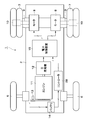
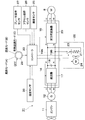
- FIG. 1 is a front view showing a dump truck according to a first embodiment of the present invention. It is a perspective view which shows the dump truck of the state which removed the vessel. It is a whole block diagram which shows the dump truck in FIG. It is an electric circuit diagram which shows the dump truck in FIG. It is explanatory drawing which shows the relationship between a mode selection switch, heat_generation
- FIGS. 1 to 6 show a first embodiment of an electric work vehicle according to the present invention.
- the dump truck 1 indicates a dump truck as an electric work vehicle.
- the dump truck 1 has a sturdy frame structure, and a vehicle body 2 that is self-propelled by front wheels 6 and rear wheels 7 as wheels to be described later, and a rear end side on the vehicle body 2.
- It is roughly constituted by a vessel 3 as a loading platform mounted as a fulcrum so that it can be raised and lowered.
- the vessel 3 has a flange 3A that almost completely covers the cabin 5 from the upper side, and is undulated (tilted) by hoist cylinders 4 disposed on the left and right sides of the vehicle body 2.
- Numeral 5 indicates a cabin provided on the front side of the vehicle body 2 located below the heel part 3A.
- the cabin 5 is disposed on the deck portion 2 ⁇ / b> A which is located on the left side of the vehicle body 2 and is a flat floor plate.
- the cabin 5 forms a driver's cab where a driver (operator) of the dump truck 1 gets in and out, and a driver's seat, a start switch, an accelerator pedal, a brake pedal, a steering handle, and a plurality of operation levers (all of which are provided) Etc.) are provided.
- Each of these front wheels 6 constitutes a steered wheel that is steered (steered) by the driver of the dump truck 1.
- Each of these rear wheels 7 constitutes a drive wheel of the dump truck 1.
- Numeral 8 indicates left and right traveling motors as drive sources provided on the lower rear side of the vehicle body 2.
- the traveling motor 8 is constituted by a large electric motor including, for example, a three-phase induction motor, a three-phase brushless DC motor, and the like, and is driven to rotate by power supply from a power control device 15 described later.
- the traveling motor 8 is provided on both the left and right sides of the vehicle body 2 in order to rotationally drive the left and right rear wheels 7 independently of each other.
- the traveling motor 8 has a rotating shaft 9 as an output shaft, and the rotating shaft 9 is rotationally driven by the traveling motor 8 in the forward direction or the reverse direction.
- the rotating shaft 9 is connected to the rear wheel 7 through, for example, a plurality of planetary gear reduction mechanisms 10. As a result, the rotation of the rotating shaft 9 is reduced by the planetary gear reduction mechanism 10 at a reduction ratio of about 30 to 40, for example, and the rear wheel 7 is driven to travel with a large rotational torque.
- the engine 11 denotes an engine as a prime mover provided in the vehicle body 2 and located below the cabin 5.
- the engine 11 is composed of, for example, a large diesel engine. As shown in FIG. 3, the engine 11 drives the main generator 12 to generate three-phase AC power (for example, about 1500 kW), and also drives the DC sub-generator 13.
- the sub-generator 13 is connected to the battery 14 serving as a power source for the controller 28 and charges the battery 14.
- the engine 11 rotationally drives a hydraulic pump (not shown) that is a hydraulic source.
- This hydraulic pump has a function of supplying pressure oil to the hoist cylinder 4 and a steering cylinder (not shown) for power steering.
- the power control device 15 denotes a power control device that performs power control of the dump truck 1 together with a controller 28 described later.
- the power control device 15 is configured by a power distribution control panel or the like that is positioned on the side of the cabin 5 and is erected on the deck portion 2 ⁇ / b> A of the vehicle body 2. As shown in FIG. 4, the power control device 15 includes an AC-DC converter 16 and a bidirectional converter 20.
- the AC-DC converter 16 is configured by using a rectifying element such as a diode or a thyristor, for example, and a rectifier 17 for full-wave rectification of AC power, and a smoothing capacitor 18 connected to a subsequent stage of the rectifier 17 for smoothing the power waveform. It is constituted by.
- This AC-DC converter 16 is connected to the output side of the main generator 12 and converts the U-phase, V-phase, and W-phase AC power output from the main generator 12 into P-phase and N-phase DC power. Convert to For this reason, the AC-DC converter 16 constitutes a DC power source together with the main generator 12.
- the AC-DC converter 16 is connected to the bidirectional converter 20 using a pair of wirings 19A and 19B.
- the bidirectional converter 20 is configured using a plurality of switching elements (not shown) using, for example, transistors, thyristors, and insulated gate bipolar transistors (IGBT).
- the bidirectional converter 20 functions as an inverter that converts DC power into three-phase AC power having a variable frequency when the dump truck 1 is traveling. For this reason, the bidirectional converter 20 converts the DC power output from the AC-DC converter 16 into U-phase, V-phase, and W-phase three-phase AC power by controlling on / off of the switching element.
- the three-phase AC power is supplied to the traveling motor 8.
- the bidirectional converter 20 functions as a converter that converts three-phase AC power into DC power when the dump truck 1 is decelerated. For this reason, the bidirectional converter 20 converts the electromotive force composed of the three-phase AC power regenerated by the traveling motor 8 into DC power by controlling on / off of the switching element, and this DC power is described later. Is output to the resistor 21.
- the resistor 21 indicates a resistor connected to the wirings 19A and 19B between the AC-DC converter 16 and the bidirectional converter 20.
- the resistor 21 is disposed in a grid box 22 having a rectangular tube shape, generates heat in accordance with DC power supplied from the bidirectional converter 20, and consumes electromotive force regenerated by the traveling motor 8. .
- a plurality of grid boxes 22 are stacked on the deck portion 2 ⁇ / b> A of the vehicle body 2 on the opposite side of the cabin 5 with the power control device 15 sandwiched in the left and right directions. Is provided.
- Each of the plurality of grid boxes 22 accommodates a resistor 21, and the plurality of resistors 21 are connected in parallel to the wirings 19A and 19B.
- a switch 23 is connected to the resistor 21 in series.
- the switch 23 is configured using various switching elements using semiconductor elements, for example, and is controlled to be switched between a connection position and a cutoff position by a controller 28 described later.
- the plurality of resistors 21 may be connected in series with each other.
- the grid box 22 may be arranged not only on the upper side of the deck portion 2A but also on the lower side of the deck portion 2A.
- Reference numeral 24 denotes a blower attached to the grid box 22.
- the blower 24 is configured by, for example, an electric motor that is driven by power feeding from the wirings 19 ⁇ / b> A and 19 ⁇ / b> B, and supplies cooling air toward the resistor 21.
- the blower 24 is provided at a position near the cabin 5 in the grid box 22 that extends in the left and right directions, and supplies cooling air toward the grid box 22.
- the cooling air passes around the resistor 21 in the grid box 22 and is blown out from the opening (exhaust part) on the left side of the grid box 22 to the outside. For this reason, the cooling air heated by the resistor 21 is discharged toward the side opposite to the cabin 5.
- Reference numeral 25 denotes a speed sensor as a running state sensor that detects whether the dump truck 1 is running or stopped.
- the speed sensor 25 is provided, for example, in the vicinity of the rotation shaft 9, detects the rotation speed of the rotation shaft 9 of the traveling motor 8, and calculates the traveling speed of the dump truck 1 based on the rotation speed. That is, the rear wheel 7 is transmitted with a rotation of a predetermined reduction ratio (for example, a reduction ratio of about 30 to 40) by a plurality of planetary gear reduction mechanisms with respect to the rotational speed of the traveling motor 8. By detecting the rotational speed of the rotating shaft 9, the rotational speed of the rear wheel 7 (the traveling speed of the vehicle) is obtained.
- the output side of the speed sensor 25 is connected to the controller 28.
- This accelerator operation sensor 26 indicates an accelerator operation sensor for detecting the operation amount of the accelerator pedal.
- This accelerator operation sensor 26 is comprised, for example by an angle sensor, a potentiometer, etc., and outputs the detection signal according to the depression state of the accelerator pedal.
- the brake operation sensor 27 indicates a brake operation sensor for detecting the operation amount of the brake pedal.
- the brake operation sensor 27 is constituted by, for example, an angle sensor, a potentiometer, and the like, and outputs a detection signal corresponding to the depression state of the brake pedal.
- the output side of the accelerator operation sensor 26 and the brake operation sensor 27 is connected to any controller 28 described later.
- the controller 28 determines whether the dump truck 1 is in an acceleration state or a deceleration state based on detection signals from the accelerator operation sensor 26 and the brake operation sensor 27.
- Numeral 28 indicates a controller as a control device constituted by a microcomputer or the like.
- the controller 28 is connected to the power control device 15 and the like, and switches and controls the switching element of the bidirectional converter 20 according to the traveling state of the dump truck 1 and makes the bidirectional converter 20 function as an inverter or a converter.
- the controller 28 causes the bidirectional converter 20 to function as an inverter so as to convert DC power from the main generator 12 into three-phase AC power.
- the controller 28 causes the bidirectional converter 20 to function as a converter so as to convert an electromotive force composed of three-phase AC power regenerated by the traveling motor 8 into DC power.
- the controller 28 is connected to the switch 23 and the blower 24, respectively, and switches connection / disconnection between the resistor 21 and the wirings 19A and 19B, and switches driving / stopping of the blower 24. Specifically, at the time of acceleration of the dump truck 1, the controller 28 turns off the switch 23 (cut off state) to stop the power consumption by the resistor 21 and stops the blower 24. On the other hand, when the dump truck 1 decelerates, the controller 28 turns on the switch 23 (connected state) to permit power consumption by the resistor 21 and drives the blower 24 to supply cooling air to the resistor 21. To do.
- the controller 28 is not limited to the configuration in which the switch 23 of the resistor 21 is always turned on when the dump truck 1 is decelerated.
- the controller 28 may be configured to periodically switch on / off the switch 23.
- the duty ratio of the switch 23 may be changed according to the electromotive force regenerated by the traveling motor 8.
- the mode selection switch 29 indicates a mode selection switch disposed in the cabin 5 and connected to the controller 28.
- the mode selection switch 29 is constituted by a selection switch such as a dial type, for example. As shown in FIGS. 4 and 5, the mode selection switch 29 selects any one of the heat generation mode A, the air blowing mode B, and the heat generation air blowing mode C, and depends on the resistor 21 according to the selected mode. The presence / absence of heat generation and the presence / absence of air blowing by the blower 24 are switched.
- the controller 28 turns on the switch 23 in a state where the blower 24 is stopped, and heats the resistor 21 by supplying power from the main generator 12.
- the controller 28 drives the blower 24 with the switch 23 turned off, and blows air from the blower 24 toward the resistor 21.
- the controller 28 drives the air blower 24 with the switch 23 turned on, heats the resistor 21 by supplying power from the main generator 12, and moves from the air blowing device 24 toward the resistor 21. Blow.
- the mode selection switch 29 can be switched to the off position. In this off position, the controller 28 turns off the switch 23 and stops the blower 24.
- switching of the switch 23 on / off and switching of the driving / stopping of the blower 24 by the mode selection switch 29 are effective when the dump truck 1 is stopped.
- the controller 28 switches on / off of the switch 23 and switches driving / stop of the blower 24 regardless of the switching state of the mode selection switch 29. That is, when the dump truck 1 is accelerated, the controller 28 turns off the switch 23 and stops the blower 24. On the other hand, when the dump truck 1 is decelerated, the controller 28 turns on the switch 23 and drives the blower 24.
- the dump truck 1 according to the first embodiment has the above-described configuration, and the operation thereof will be described next.
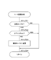
- the controller 28 executes the control process shown in FIG. 6 and controls the bidirectional converter 20, the resistor 21, and the blower 24 in accordance with the traveling state of the vehicle body 2. Specifically, in step 1, the controller 28 determines whether or not the dump truck 1 is traveling based on the output signal of the speed sensor 25. When the dump truck 1 is traveling, “YES” is determined in the step 1, and the process proceeds to the step 2. In step 2, it is determined based on detection signals from the accelerator operation sensor 26 and the brake operation sensor 27 whether or not the dump truck 1 is accelerating.
- Step 2 When it is determined “YES” in Step 2, the dump truck 1 is accelerating. For this reason, the controller 28 proceeds to step 3, causes the bidirectional converter 20 to function as an inverter, converts the DC power from the main generator 12 into three-phase AC power, and supplies it to the traveling motor 8. At this time, the controller 28 turns off the switch 23 to stop the power consumption by the resistor 21 and stops the blower 24.
- Step 2 when it is determined “NO” in Step 2, the dump truck 1 is decelerating. For this reason, the controller 28 proceeds to step 4 to cause the bidirectional converter 20 to function as a converter, and converts the electromotive force composed of the three-phase AC power regenerated by the traveling motor 8 into DC power.
- the controller 28 turns on the switch 23 (connected state) to permit power consumption by the resistor 21 and drives the blower 24 to supply cooling air toward the resistor 21. As a result, the electromotive force regenerated by the traveling motor 8 is consumed as the resistor 21 generates heat.
- Step 1 When it is determined “NO” in Step 1, the dump truck 1 is stopped. For this reason, the controller 28 proceeds to step 5 to stop the operation of the bidirectional converter 20 and controls the operation of the resistor 21 and the blower 24 according to the mode selected by the mode selection switch 29.
- the resistor 21 is disposed in a portion of the dump truck 1 that is easily exposed to the outside air in order to enhance the cooling effect. For this reason, for example, the resistor 21 may freeze when it is cold, or the resistor 21 may be wetted by rainwater when it rains. In this case, the insulation between the circuit for the resistor 21 and the vehicle body 2 may be reduced, so that the regenerative power cannot be consumed by the resistor 21 and the braking force may be reduced.
- the mode selection switch 29 for selecting any one of the heat generation mode A, the air blowing mode B, and the heat generating air blowing mode C is provided. For this reason, the driver selects an appropriate mode from among these three modes according to the state of the resistor 21 and the outside air condition, such as whether the resistor 21 is frozen or flooded, the amount of rainfall or the amount of snowfall, etc. can do.
- the driver uses the mode selection switch 29 to select the heat generation mode A in which only heat generation is performed.
- moisture content can be evaporated by the heat_generation
- the driver uses the mode selection switch 29 to select the air blowing mode B in which only air is blown.
- the water collected around the resistor 21 can be blown off by the air blown from the blower 24.
- the driver uses the mode selection switch 29 to select the heat generation air blowing mode C in which heat generation and air blowing are performed together. Accordingly, the resistor 21 can be dried by blowing air from the blower 24 while melting the ice by the heat generated by the resistor 21.
- the driver can select an appropriate mode according to the state of the resistor 21 and the state of the outside air by using the mode selection switch 29, so that the resistor 21 is previously set before the dump truck 1 travels. Insulation can be enhanced, and the regenerative power of the traveling motor 8 can be reliably consumed by the resistor 21.
- the controller 28 controls the operations of the bidirectional converter 20, the resistor 21, and the blower 24 according to acceleration and deceleration of the vehicle body 2. For this reason, during acceleration of the vehicle body 2, the DC power is converted into AC power by the bidirectional converter 20 and supplied to the traveling motor 8 while the heat generation by the resistor 21 and the ventilation by the blower 24 are stopped. it can. On the other hand, when the vehicle body 2 decelerates, the bidirectional converter 20 can convert the output of AC power from the traveling motor 8 into DC power, and the DC power is consumed by the heat generated by the resistor 21, and the blower The resistor 21 can be cooled by the ventilation by 24.
- the controller 28 stops the operation of the bidirectional converter 20 and controls the operation of the resistor 21 and the blower 24 according to the mode selected by the mode selection switch 29. .
- operator can select the optimal mode according to the condition of the resistor 21 and the condition of external air before driving
- FIG. 7 and FIG. 8 show a second embodiment according to the present invention.
- the feature of the second embodiment is that the controller automatically changes from the heat generation mode to the air blowing mode when the temperature sensor does not detect a temperature rise when the heat generation mode is selected.
- the same components as those in the first embodiment are denoted by the same reference numerals, and the description thereof is omitted.
- This dump truck 31 indicates a dump truck according to the second embodiment.
- This dump truck 31 is substantially the same as the dump truck 1 according to the first embodiment, and includes a traveling motor 8, an engine 11, a main generator 12, a power control device 15, a resistor 21, a switch 23, a blower 24, a mode.
- a selection switch 29 and the like are provided.
- This temperature sensor 32 indicates a temperature sensor provided around the resistor 21. This temperature sensor 32 detects the temperature of the resistor 21 or its surroundings, and outputs a detection signal corresponding to the detected temperature. The output side of the temperature sensor 32 is connected to a controller 33 described later.
- the controller 33 indicates a controller according to the second embodiment.
- the controller 33 is configured in substantially the same manner as the controller 28 according to the first embodiment, is connected to the power control device 15 and the like, and switches the switching element of the bidirectional converter 20 according to the traveling state of the dump truck 1 and the like.
- the controller 33 switches between the presence / absence of heat generated by the resistor 21 and the presence / absence of air blown by the blower 24 in accordance with the mode selected by the mode selection switch 29.
- the controller 33 is different from the controller 28 according to the first embodiment in that the mode change process shown in FIG. 8 is performed.
- step 11 it is determined whether or not the heat generation mode A is selected by the mode selection switch 29. If “NO” is determined in the step 11, the process proceeds to a step 14 and returns. On the other hand, when it is determined “YES” in step 11, the process proceeds to step 12.
- step 12 based on the detection signal from the temperature sensor 32, it is detected whether or not the temperature of the resistor 21 has risen compared to when the switch 23 is turned off. If the ambient temperature of the resistor 21 is higher than, for example, a predetermined temperature, for example, “YES” is determined in step 12 to maintain the heat generation mode A, and the routine proceeds to step 14 and returns.
- a predetermined temperature for example, “YES”
- the resistor 21 determines with "NO" at step 12, it transfers to step 13, and it changes automatically from the heat_generation
- the controller 33 selects the heat generation mode A from the heat generation mode A when the temperature sensor 32 does not detect the temperature rise of the resistor 21 while the mode selection switch 29 selects the heat generation mode A. It is configured to change automatically.
- FIG. 9 and FIG. 10 show a third embodiment according to the present invention.
- the feature of the third embodiment is that the controller automatically changes from the blowing mode to the heat generation mode when the pressure difference detected by the differential pressure sensor when the blowing mode is selected is smaller than the minimum pressure difference. is there.
- the same components as those in the first embodiment are denoted by the same reference numerals, and the description thereof is omitted.
- This dump truck 41 indicates a dump truck according to the third embodiment.
- This dump truck 41 is substantially the same as the dump truck 1 according to the first embodiment, and includes a traveling motor 8, an engine 11, a main generator 12, a power control device 15, a resistor 21, a switch 23, a blower 24, a mode.
- a selection switch 29 and the like are provided.
- the differential pressure sensor 42 indicates a differential pressure sensor provided in the grid box 22.
- the differential pressure sensor 42 detects a pressure difference ⁇ P between the upstream side and the downstream side of the resistor 21 with respect to the blowing direction from the blower 24, and outputs a detection signal corresponding to the pressure difference ⁇ P.
- the output side of the differential pressure sensor 42 is connected to a controller 43 described later.
- the controller 43 indicates a controller according to the third embodiment.
- the controller 43 is configured in substantially the same manner as the controller 28 according to the first embodiment, is connected to the power control device 15 and the like, and switches the switching element of the bidirectional converter 20 according to the traveling state of the dump truck 1 and the like. To control the bidirectional converter 20 to function as an inverter or a converter. Further, the controller 43 switches between the presence / absence of heat generated by the resistor 21 and the presence / absence of air blown by the blower 24 in accordance with the mode selected by the mode selection switch 29. However, the controller 43 is different from the controller 28 according to the first embodiment in that the mode change process shown in FIG. 10 is performed.
- step 21 it is determined whether or not the air blowing mode B is selected by the mode selection switch 29. If “NO” is determined in the step 21, the process proceeds to a step 24 and returns. On the other hand, if “YES” is determined in the step 21, the process proceeds to the step 22.
- step 22 based on the detection signal from the differential pressure sensor 42, it is determined whether or not the pressure difference ⁇ P detected by the differential pressure sensor 42 is larger than a predetermined minimum pressure difference ⁇ Pmin.
- a predetermined minimum pressure difference ⁇ Pmin a predetermined minimum pressure difference ⁇ Pmin.
- the controller 43 when the air pressure mode B is selected by the mode selection switch 29 and the pressure difference ⁇ P detected by the differential pressure sensor 42 is smaller than the minimum pressure difference ⁇ Pmin, the controller 43 generates the heat generation mode. The configuration is changed to A.
- the selection of the blowing mode B is inappropriate, for example, when the blower 24 has failed. It is considered to be a state.
- the controller 43 since the controller 43 changes to the heat generation mode A in which the resistor 21 generates heat, the moisture can be evaporated by the heat generated by the resistor 21 and the insulation of the resistor 21 can be improved. Thereby, it is possible to automatically change from the inappropriate air blowing mode B to the heat generation mode A, perform an appropriate operation, and minimize the stop time of the machine.
- the air blowing mode B is maintained when the pressure difference ⁇ P detected by the differential pressure sensor 42 is larger than the minimum pressure difference ⁇ Pmin.
- the present invention is not limited to this.
- an abnormality such as clogging may occur in the exhaust part. Both may be configured to stop and output an alarm to notify the driver to that effect.
- the mode change processing shown in FIGS. 8 and 10 shows a specific example of the mode change processing device of the present invention.
- the rear-wheel drive type dump trucks 1, 31, 41 have been described as examples of the electric work vehicle.
- the present invention is not limited to this, and may be applied to, for example, a front-wheel drive type or a four-wheel drive type dump truck that drives both front and rear wheels.
- the working vehicle including traveling wheels may be applied to, for example, a wheel crane, a wheel hydraulic excavator, or the like.
Abstract
Description
2 車体
6 前輪
7 後輪(駆動輪)
8 走行用モータ(電動モータ)
11 エンジン
12 主発電機
15 電力制御装置
16 交流-直流変換器
20 双方向変換器
21 抵抗器
22 グリッドボックス
23 スイッチ
24 送風機
28,33,43 コントローラ
29 モード選択スイッチ
32 温度センサ
42 差圧センサ
A 発熱モード
B 送風モード
C 発熱送風モード 1,31,41 Dump truck (Electric work vehicle)
2
8 Traveling motor (electric motor)
DESCRIPTION OF
Claims (5)
- 車体(2)に設けられた走行駆動用の電動モータ(8)と、
前記車体(2)に設けられ直流電源(12,16)からの直流電力を可変周波数の交流電力に変換して該電動モータ(8)を駆動すると共に該電動モータ(8)からの交流電力の出力を直流電力に変換する双方向変換器(20)と、
前記車体(2)に設けられ前記電動モータ(8)で回生される起電力を消費するように該双方向変換器(20)に接続された抵抗器(21)と、
該抵抗器(21)に冷却風を供給する送風機(24)と、
モード選択スイッチ(29)とを備え、
前記モード選択スイッチ(29)は、前記抵抗器(21)を発熱させる発熱モードと、前記送風機(24)を用いて前記抵抗器(21)に送風を行う送風モードと、前記抵抗器(21)による発熱と前記送風機(24)による送風を一緒に行う発熱送風モードとのうち、いずれか1つのモードを選択する構成としてなる電動式作業車両。 An electric motor (8) for driving driving provided on the vehicle body (2);
The DC power supplied from the DC power source (12, 16) provided in the vehicle body (2) is converted into AC power having a variable frequency to drive the electric motor (8) and the AC power from the electric motor (8) A bidirectional converter (20) for converting the output into DC power;
A resistor (21) connected to the bidirectional converter (20) so as to consume an electromotive force provided in the vehicle body (2) and regenerated by the electric motor (8);
A blower (24) for supplying cooling air to the resistor (21);
A mode selection switch (29),
The mode selection switch (29) includes a heat generation mode in which the resistor (21) generates heat, a ventilation mode in which the resistor (21) is blown using the blower (24), and the resistor (21). An electric work vehicle configured to select one of a heat generation mode and a heat generation air blowing mode in which air is blown by the blower (24) together. - 前記双方向変換器(20)、前記抵抗器(21)および前記送風機(24)には、これらの動作を制御するコントローラ(28,33,43)を接続して設け、
該コントローラ(28,33,43)は、前記車体(2)が走行しているときには、前記車体(2)の加速と減速とに応じて前記双方向変換器(20)、前記抵抗器(21)および前記送風機(24)の動作を制御し、前記車体(2)が停止しているときには、前記モード選択スイッチ(29)によって選択されたモードに応じて前記抵抗器(21)および前記送風機(24)の動作を制御する構成としてなる請求項1に記載の電動式作業車両。 The bidirectional converter (20), the resistor (21) and the blower (24) are connected to a controller (28, 33, 43) for controlling these operations,
When the vehicle body (2) is running, the controller (28, 33, 43) responds to acceleration and deceleration of the vehicle body (2) according to the bidirectional converter (20) and the resistor (21). ) And the blower (24), and when the vehicle body (2) is stopped, the resistor (21) and the blower () according to the mode selected by the mode selection switch (29). 24. The electric work vehicle according to claim 1, which is configured to control the operation of 24). - 前記コントローラ(28,33,43)は、前記車体(2)が加速しているときには、前記双方向変換器(20)によって前記直流電源(12,16)からの直流電力を交流電力に変換して前記電動モータ(8)に供給し、前記抵抗器(21)の発熱を停止させると共に、前記送風機(24)の送風を停止させる構成とし、
前記車体(2)が減速しているときには、前記双方向変換器(20)によって前記電動モータ(8)で回生される交流の起電力を直流電力に変換し、該直流電力を消費するように前記抵抗器(21)を発熱させると共に、前記送風機(24)によって前記抵抗器(21)に冷却風を供給する構成とし、
前記車体(2)が停止しているときには、前記双方向変換器(20)の動作を停止させて、前記モード選択スイッチ(29)によって選択されたモードに応じて前記抵抗器(21)および前記送風機(24)の動作を制御する構成としてなる請求項2に記載の電動式作業車両。 When the vehicle body (2) is accelerating, the controller (28, 33, 43) converts DC power from the DC power source (12, 16) into AC power by the bidirectional converter (20). Supply to the electric motor (8), and stop the heat generation of the resistor (21), and stop the blowing of the blower (24),
When the vehicle body (2) is decelerating, the bidirectional converter (20) converts the AC electromotive force regenerated by the electric motor (8) into DC power and consumes the DC power. The resistor (21) generates heat, and the blower (24) supplies cooling air to the resistor (21).
When the vehicle body (2) is stopped, the operation of the bidirectional converter (20) is stopped, and the resistor (21) and the resistor are controlled according to the mode selected by the mode selection switch (29). The electric work vehicle according to claim 2, wherein the electric work vehicle is configured to control the operation of the blower (24). - 前記抵抗器(21)の温度を検出する温度センサ(32)を設け、
前記モード選択スイッチ(29)によって前記発熱モードを選択した状態で、該温度センサ(32)によって前記抵抗器(21)の温度上昇を検出したときには前記発熱モードを維持し、該温度センサ(32)によって前記抵抗器(21)の温度上昇を検出しないときには前記送風モードに変更するモード変更処理装置を備える構成としてなる請求項1に記載の電動式作業車両。 A temperature sensor (32) for detecting the temperature of the resistor (21) is provided;
When the temperature sensor (32) detects a temperature rise of the resistor (21) in a state where the heat generation mode is selected by the mode selection switch (29), the heat generation mode is maintained, and the temperature sensor (32) The electric work vehicle according to claim 1, further comprising: a mode change processing device that changes to the air blowing mode when the temperature rise of the resistor (21) is not detected. - 前記抵抗器(21)は、前記送風機(24)が取付けられた箱状のグリッドボックス(22)に収容され、
該グリッドボックス(22)には、前記送風機(24)からの送風方向に対して前記抵抗器(21)の上流側と下流側との間で圧力差を検出する差圧センサ(42)を設け、
前記モード選択スイッチ(29)によって前記送風モードを選択した状態で、該差圧センサ(42)によって検出した圧力差が予め決められた最低圧力差よりも大きいときには前記送風モードを維持し、該差圧センサ(42)によって検出した圧力差が前記最低圧力差よりも小さいときには前記発熱モードに変更するモード変更処理装置を備える構成としてなる請求項1に記載の電動式作業車両。 The resistor (21) is housed in a box-shaped grid box (22) to which the blower (24) is attached,
The grid box (22) is provided with a differential pressure sensor (42) for detecting a pressure difference between the upstream side and the downstream side of the resistor (21) with respect to the blowing direction from the blower (24). ,
When the air pressure mode is selected by the mode selection switch (29) and the pressure difference detected by the differential pressure sensor (42) is larger than a predetermined minimum pressure difference, the air flow mode is maintained and the difference is maintained. The electric work vehicle according to claim 1, further comprising a mode change processing device that changes to the heat generation mode when the pressure difference detected by the pressure sensor (42) is smaller than the minimum pressure difference.
Priority Applications (5)
| Application Number | Priority Date | Filing Date | Title |
|---|---|---|---|
| EP11806550.7A EP2594426A4 (en) | 2010-07-15 | 2011-05-19 | Electric work vehicle |
| AU2011277754A AU2011277754B8 (en) | 2010-07-15 | 2011-05-19 | Electric working vehicle |
| CN201180016543.7A CN102834283B (en) | 2010-07-15 | 2011-05-19 | Electric work vehicle |
| US13/503,687 US8925661B2 (en) | 2010-07-15 | 2011-05-19 | Electric working vehicle |
| JP2012524482A JP5415619B2 (en) | 2010-07-15 | 2011-05-19 | Electric work vehicle |
Applications Claiming Priority (2)
| Application Number | Priority Date | Filing Date | Title |
|---|---|---|---|
| JP2010-160645 | 2010-07-15 | ||
| JP2010160645 | 2010-07-15 |
Publications (1)
| Publication Number | Publication Date |
|---|---|
| WO2012008219A1 true WO2012008219A1 (en) | 2012-01-19 |
Family
ID=45469230
Family Applications (1)
| Application Number | Title | Priority Date | Filing Date |
|---|---|---|---|
| PCT/JP2011/061525 WO2012008219A1 (en) | 2010-07-15 | 2011-05-19 | Electric work vehicle |
Country Status (6)
| Country | Link |
|---|---|
| US (1) | US8925661B2 (en) |
| EP (1) | EP2594426A4 (en) |
| JP (2) | JP5415619B2 (en) |
| CN (1) | CN102834283B (en) |
| AU (1) | AU2011277754B8 (en) |
| WO (1) | WO2012008219A1 (en) |
Cited By (3)
| Publication number | Priority date | Publication date | Assignee | Title |
|---|---|---|---|---|
| WO2013162039A1 (en) * | 2012-04-27 | 2013-10-31 | 日立建機株式会社 | Life prediction system for dump truck speed reducer gear and life prediction method for dump truck speed reducer gear |
| CN104386004A (en) * | 2014-10-28 | 2015-03-04 | 广州电力机车有限公司 | 60 t mine dumping vehicle control system |
| JP2016078714A (en) * | 2014-10-20 | 2016-05-16 | 日立建機株式会社 | Dump truck |
Families Citing this family (20)
| Publication number | Priority date | Publication date | Assignee | Title |
|---|---|---|---|---|
| CN203876561U (en) * | 2013-04-17 | 2014-10-15 | 栾亚伦 | A sliding-typed electric engineering mechanical chassis |
| US20150158390A1 (en) * | 2013-12-09 | 2015-06-11 | Textron Inc. | Using DC Motor With A Controller As A Generator |
| US10375901B2 (en) | 2014-12-09 | 2019-08-13 | Mtd Products Inc | Blower/vacuum |
| EP3280607B1 (en) * | 2015-04-08 | 2023-11-29 | KATO IMER S.p.A. | Gearmotor |
| US9925999B2 (en) | 2015-09-29 | 2018-03-27 | Radio Flyer Inc. | Power assist wagon |
| CN107539192B (en) * | 2016-06-29 | 2019-08-13 | 比亚迪股份有限公司 | A kind of electronic mine dumper |
| EP3511192B1 (en) | 2016-09-08 | 2022-05-11 | Hitachi Construction Machinery Co., Ltd. | Regenerative braking device and dump truck |
| US10583852B2 (en) | 2016-11-02 | 2020-03-10 | Radio Flyer Inc. | Foldable wagon |
| CN106585390B (en) * | 2016-11-30 | 2019-04-16 | 金龙联合汽车工业(苏州)有限公司 | A kind of brake resistor system for electric vehicle and its control method |
| CN107276371A (en) * | 2017-08-01 | 2017-10-20 | 徐州徐工矿山机械有限公司 | A kind of converter cabinet aeration radiation system of electric transmission quarry tipper |
| JP6909694B2 (en) * | 2017-09-29 | 2021-07-28 | 日立建機株式会社 | Work vehicle power regeneration system |
| USD866676S1 (en) | 2017-11-02 | 2019-11-12 | Radio Flyer Inc. | Foldable wagon |
| JP6738497B2 (en) * | 2018-02-23 | 2020-08-12 | 日立建機株式会社 | Work vehicle power regeneration system |
| JP6918741B2 (en) * | 2018-04-27 | 2021-08-11 | 株式会社クボタ | Work equipment and work equipment equipped with this work equipment |
| EP3787183A4 (en) * | 2018-04-27 | 2022-01-26 | Kubota Corporation | Working device and working machine provided therewith |
| US11938979B2 (en) * | 2019-01-14 | 2024-03-26 | Transportation Ip Holdings, Llc | Cooling system for a vehicle |
| CN113291142B (en) * | 2021-05-13 | 2022-11-11 | 广西大学 | Intelligent driving system and control method thereof |
| SE544948C2 (en) * | 2021-06-17 | 2023-02-07 | Scania Cv Ab | System for braking an electrified vehicle |
| EP4163146A1 (en) * | 2021-10-08 | 2023-04-12 | Volvo Construction Equipment AB | A material transportation system |
| CN114537242B (en) * | 2022-03-15 | 2023-10-27 | 福建宏大时代新能源科技有限公司 | 100-ton-level pure-electric-driven mining dump truck |
Citations (3)
| Publication number | Priority date | Publication date | Assignee | Title |
|---|---|---|---|---|
| JPS62110402A (en) * | 1985-11-06 | 1987-05-21 | Fuji Electric Co Ltd | Electric locomotive for steep slope |
| JPH08154304A (en) * | 1994-11-29 | 1996-06-11 | Nissan Motor Co Ltd | Regenerative brake for electric vehicle |
| JP2010088289A (en) * | 2008-09-03 | 2010-04-15 | Hitachi Constr Mach Co Ltd | Dump truck |
Family Cites Families (21)
| Publication number | Priority date | Publication date | Assignee | Title |
|---|---|---|---|---|
| US4307300A (en) * | 1978-03-02 | 1981-12-22 | Kabushiki Kaisha Komatsu Seisakusho | Dump truck with safety circuit |
| DE3500988C1 (en) * | 1985-01-09 | 1986-02-13 | Roland 6231 Schwalbach Sommer | Probe for measuring gaseous or liquid flows with respect to direction and strength |
| US4843880A (en) * | 1985-01-14 | 1989-07-04 | Roland Sommer | Method for measuring the direction and force of gaseous or liquid flows and probe for carrying out this method |
| US5280223A (en) * | 1992-03-31 | 1994-01-18 | General Electric Company | Control system for an electrically propelled traction vehicle |
| JPH0646505A (en) * | 1992-07-23 | 1994-02-18 | Toshiba Corp | Dynamic brake system |
| US6186254B1 (en) * | 1996-05-29 | 2001-02-13 | Xcelliss Fuel Cell Engines Inc. | Temperature regulating system for a fuel cell powered vehicle |
| JP2001030795A (en) * | 1999-07-19 | 2001-02-06 | Nissan Motor Co Ltd | Follow-up control for vehicle in front |
| US8025115B2 (en) * | 2003-06-02 | 2011-09-27 | General Electric Company | Hybrid vehicle power control systems and methods |
| AU2005251187B2 (en) * | 2004-05-27 | 2008-09-18 | Siemens Aktiengesellschaft | AC/AC converter for hybrid vehicles |
| US20060047400A1 (en) * | 2004-08-25 | 2006-03-02 | Raj Prakash | Method and apparatus for braking and stopping vehicles having an electric drive |
| JP4585842B2 (en) * | 2004-12-10 | 2010-11-24 | 株式会社日立製作所 | Vehicle electric drive device |
| JP2006230084A (en) * | 2005-02-17 | 2006-08-31 | Hitachi Ltd | Ac drive device, vehicle controller, power conversion method, and vehicle control method |
| US8453772B2 (en) * | 2005-08-01 | 2013-06-04 | Albert W. Brown | Manually operated electrical control and installation scheme for electric hybrid vehicles |
| JP2008017563A (en) * | 2006-07-03 | 2008-01-24 | Hitachi Ltd | Vehicle controller, vehicle controlling method, and vehicle |
| AU2007292710B2 (en) * | 2006-09-05 | 2010-05-13 | Hitachi Construction Machinery Co., Ltd. | Brake system of electrically driven dump truck |
| DE102006051337A1 (en) * | 2006-10-31 | 2008-05-08 | Knorr-Bremse Systeme für Schienenfahrzeuge GmbH | Traction drive of a rail vehicle for driving and for regenerative braking |
| US8001906B2 (en) * | 2007-05-07 | 2011-08-23 | General Electric Company | Electric drive vehicle retrofit system and associated method |
| US7854282B2 (en) * | 2007-12-10 | 2010-12-21 | International Humanities Center | Hybrid electric vehicle |
| CN201201523Y (en) * | 2008-03-27 | 2009-03-04 | 上海工程技术大学 | Braking energy recovery apparatus for track traffic vehicle |
| US8324846B2 (en) * | 2008-09-15 | 2012-12-04 | Caterpillar Inc. | Electric drive retarding system and method |
| US8499909B2 (en) * | 2009-10-23 | 2013-08-06 | Siemens Industry, Inc. | Peak demand reduction in mining haul trucks utilizing an on-board energy storage system |
-
2011
- 2011-05-19 EP EP11806550.7A patent/EP2594426A4/en not_active Withdrawn
- 2011-05-19 JP JP2012524482A patent/JP5415619B2/en not_active Expired - Fee Related
- 2011-05-19 WO PCT/JP2011/061525 patent/WO2012008219A1/en active Application Filing
- 2011-05-19 AU AU2011277754A patent/AU2011277754B8/en not_active Ceased
- 2011-05-19 US US13/503,687 patent/US8925661B2/en not_active Expired - Fee Related
- 2011-05-19 CN CN201180016543.7A patent/CN102834283B/en not_active Expired - Fee Related
-
2013
- 2013-07-12 JP JP2013146432A patent/JP2014018063A/en active Pending
Patent Citations (3)
| Publication number | Priority date | Publication date | Assignee | Title |
|---|---|---|---|---|
| JPS62110402A (en) * | 1985-11-06 | 1987-05-21 | Fuji Electric Co Ltd | Electric locomotive for steep slope |
| JPH08154304A (en) * | 1994-11-29 | 1996-06-11 | Nissan Motor Co Ltd | Regenerative brake for electric vehicle |
| JP2010088289A (en) * | 2008-09-03 | 2010-04-15 | Hitachi Constr Mach Co Ltd | Dump truck |
Non-Patent Citations (1)
| Title |
|---|
| See also references of EP2594426A4 * |
Cited By (4)
| Publication number | Priority date | Publication date | Assignee | Title |
|---|---|---|---|---|
| WO2013162039A1 (en) * | 2012-04-27 | 2013-10-31 | 日立建機株式会社 | Life prediction system for dump truck speed reducer gear and life prediction method for dump truck speed reducer gear |
| JP2013231673A (en) * | 2012-04-27 | 2013-11-14 | Hitachi Constr Mach Co Ltd | Life prediction system of speed reducer gear of dump truck |
| JP2016078714A (en) * | 2014-10-20 | 2016-05-16 | 日立建機株式会社 | Dump truck |
| CN104386004A (en) * | 2014-10-28 | 2015-03-04 | 广州电力机车有限公司 | 60 t mine dumping vehicle control system |
Also Published As
| Publication number | Publication date |
|---|---|
| AU2011277754B2 (en) | 2013-09-19 |
| AU2011277754A1 (en) | 2012-05-24 |
| AU2011277754A8 (en) | 2014-04-10 |
| JP5415619B2 (en) | 2014-02-12 |
| AU2011277754B8 (en) | 2014-04-10 |
| US8925661B2 (en) | 2015-01-06 |
| CN102834283A (en) | 2012-12-19 |
| US20130075170A1 (en) | 2013-03-28 |
| EP2594426A4 (en) | 2018-01-10 |
| JP2014018063A (en) | 2014-01-30 |
| JPWO2012008219A1 (en) | 2013-09-05 |
| CN102834283B (en) | 2015-04-15 |
| EP2594426A1 (en) | 2013-05-22 |
Similar Documents
| Publication | Publication Date | Title |
|---|---|---|
| JP5415619B2 (en) | Electric work vehicle | |
| AU2011292206B2 (en) | Method and system for eliminating fuel consumption during dynamic braking of electric drive machines | |
| AU2009212974B2 (en) | Electric drive retarding system and method | |
| US8376476B2 (en) | Brake system in electric drive dump truck | |
| AU2012348038B2 (en) | Method and apparatus to eliminate fuel use for electric drive machines during trolley operation | |
| JP6864781B2 (en) | Electric drive vehicle | |
| JP2007313992A (en) | Drive system for electrically-driven dump truck | |
| CN106945661A (en) | A kind of control system and control method for the parking of electric automobile ramp | |
| AU2012348038A1 (en) | Method and apparatus to eliminate fuel use for electric drive machines during trolley operation | |
| JP2012147614A (en) | Motor controller for driving vehicle | |
| JP6343019B2 (en) | Transport vehicle | |
| US7091627B2 (en) | Controller for a power train | |
| US7466091B2 (en) | Brake responsive vehicle electric drive system | |
| JP2009219191A (en) | Regeneration power controller and regeneration power control method of vehicle | |
| JP4309617B2 (en) | Industrial locomotive | |
| JP3452514B2 (en) | Driving drive system for industrial vehicles responding to bad weather | |
| WO2018104975A1 (en) | Apparatus for selectively sharing the power of a multidrive unit vehicle | |
| JP2015139239A (en) | Motor drive device of electric vehicle | |
| JP2007313994A (en) | Drive system for electrically-driven dump truck |
Legal Events
| Date | Code | Title | Description |
|---|---|---|---|
| WWE | Wipo information: entry into national phase |
Ref document number: 201180016543.7 Country of ref document: CN |
|
| 121 | Ep: the epo has been informed by wipo that ep was designated in this application |
Ref document number: 11806550 Country of ref document: EP Kind code of ref document: A1 |
|
| WWE | Wipo information: entry into national phase |
Ref document number: 2012524482 Country of ref document: JP |
|
| WWE | Wipo information: entry into national phase |
Ref document number: 13503687 Country of ref document: US |
|
| WWE | Wipo information: entry into national phase |
Ref document number: 2011277754 Country of ref document: AU |
|
| ENP | Entry into the national phase |
Ref document number: 2011277754 Country of ref document: AU Date of ref document: 20110519 Kind code of ref document: A |
|
| WWE | Wipo information: entry into national phase |
Ref document number: 2011806550 Country of ref document: EP |
|
| NENP | Non-entry into the national phase |
Ref country code: DE |