EP3640008A1 - Imprimantes tridimensionnelle dans laquelle un mécanisme mobile sert à réduire les vibrations - Google Patents
Imprimantes tridimensionnelle dans laquelle un mécanisme mobile sert à réduire les vibrations Download PDFInfo
- Publication number
- EP3640008A1 EP3640008A1 EP18201045.4A EP18201045A EP3640008A1 EP 3640008 A1 EP3640008 A1 EP 3640008A1 EP 18201045 A EP18201045 A EP 18201045A EP 3640008 A1 EP3640008 A1 EP 3640008A1
- Authority
- EP
- European Patent Office
- Prior art keywords
- printer
- counterweight
- housing
- plane
- print head
- Prior art date
- Legal status (The legal status is an assumption and is not a legal conclusion. Google has not performed a legal analysis and makes no representation as to the accuracy of the status listed.)
- Ceased
Links
Images

Classifications
-
- B—PERFORMING OPERATIONS; TRANSPORTING
- B29—WORKING OF PLASTICS; WORKING OF SUBSTANCES IN A PLASTIC STATE IN GENERAL
- B29C—SHAPING OR JOINING OF PLASTICS; SHAPING OF MATERIAL IN A PLASTIC STATE, NOT OTHERWISE PROVIDED FOR; AFTER-TREATMENT OF THE SHAPED PRODUCTS, e.g. REPAIRING
- B29C64/00—Additive manufacturing, i.e. manufacturing of three-dimensional [3D] objects by additive deposition, additive agglomeration or additive layering, e.g. by 3D printing, stereolithography or selective laser sintering
- B29C64/20—Apparatus for additive manufacturing; Details thereof or accessories therefor
- B29C64/227—Driving means
-
- B—PERFORMING OPERATIONS; TRANSPORTING
- B33—ADDITIVE MANUFACTURING TECHNOLOGY
- B33Y—ADDITIVE MANUFACTURING, i.e. MANUFACTURING OF THREE-DIMENSIONAL [3-D] OBJECTS BY ADDITIVE DEPOSITION, ADDITIVE AGGLOMERATION OR ADDITIVE LAYERING, e.g. BY 3-D PRINTING, STEREOLITHOGRAPHY OR SELECTIVE LASER SINTERING
- B33Y30/00—Apparatus for additive manufacturing; Details thereof or accessories therefor
-
- B—PERFORMING OPERATIONS; TRANSPORTING
- B33—ADDITIVE MANUFACTURING TECHNOLOGY
- B33Y—ADDITIVE MANUFACTURING, i.e. MANUFACTURING OF THREE-DIMENSIONAL [3-D] OBJECTS BY ADDITIVE DEPOSITION, ADDITIVE AGGLOMERATION OR ADDITIVE LAYERING, e.g. BY 3-D PRINTING, STEREOLITHOGRAPHY OR SELECTIVE LASER SINTERING
- B33Y40/00—Auxiliary operations or equipment, e.g. for material handling
-
- B—PERFORMING OPERATIONS; TRANSPORTING
- B29—WORKING OF PLASTICS; WORKING OF SUBSTANCES IN A PLASTIC STATE IN GENERAL
- B29C—SHAPING OR JOINING OF PLASTICS; SHAPING OF MATERIAL IN A PLASTIC STATE, NOT OTHERWISE PROVIDED FOR; AFTER-TREATMENT OF THE SHAPED PRODUCTS, e.g. REPAIRING
- B29C64/00—Additive manufacturing, i.e. manufacturing of three-dimensional [3D] objects by additive deposition, additive agglomeration or additive layering, e.g. by 3D printing, stereolithography or selective laser sintering
- B29C64/10—Processes of additive manufacturing
- B29C64/106—Processes of additive manufacturing using only liquids or viscous materials, e.g. depositing a continuous bead of viscous material
- B29C64/118—Processes of additive manufacturing using only liquids or viscous materials, e.g. depositing a continuous bead of viscous material using filamentary material being melted, e.g. fused deposition modelling [FDM]
-
- B—PERFORMING OPERATIONS; TRANSPORTING
- B29—WORKING OF PLASTICS; WORKING OF SUBSTANCES IN A PLASTIC STATE IN GENERAL
- B29C—SHAPING OR JOINING OF PLASTICS; SHAPING OF MATERIAL IN A PLASTIC STATE, NOT OTHERWISE PROVIDED FOR; AFTER-TREATMENT OF THE SHAPED PRODUCTS, e.g. REPAIRING
- B29C64/00—Additive manufacturing, i.e. manufacturing of three-dimensional [3D] objects by additive deposition, additive agglomeration or additive layering, e.g. by 3D printing, stereolithography or selective laser sintering
- B29C64/30—Auxiliary operations or equipment
- B29C64/386—Data acquisition or data processing for additive manufacturing
- B29C64/393—Data acquisition or data processing for additive manufacturing for controlling or regulating additive manufacturing processes
-
- B—PERFORMING OPERATIONS; TRANSPORTING
- B33—ADDITIVE MANUFACTURING TECHNOLOGY
- B33Y—ADDITIVE MANUFACTURING, i.e. MANUFACTURING OF THREE-DIMENSIONAL [3-D] OBJECTS BY ADDITIVE DEPOSITION, ADDITIVE AGGLOMERATION OR ADDITIVE LAYERING, e.g. BY 3-D PRINTING, STEREOLITHOGRAPHY OR SELECTIVE LASER SINTERING
- B33Y10/00—Processes of additive manufacturing
-
- B—PERFORMING OPERATIONS; TRANSPORTING
- B33—ADDITIVE MANUFACTURING TECHNOLOGY
- B33Y—ADDITIVE MANUFACTURING, i.e. MANUFACTURING OF THREE-DIMENSIONAL [3-D] OBJECTS BY ADDITIVE DEPOSITION, ADDITIVE AGGLOMERATION OR ADDITIVE LAYERING, e.g. BY 3-D PRINTING, STEREOLITHOGRAPHY OR SELECTIVE LASER SINTERING
- B33Y50/00—Data acquisition or data processing for additive manufacturing
- B33Y50/02—Data acquisition or data processing for additive manufacturing for controlling or regulating additive manufacturing processes
Definitions
- the present invention relates to a 3D (three-dimensional) printer which comprises at least one print head and at least one counterweight.
- the counterweight and the printhead are moved in mirror image to one another within the printer housing.
- the present invention relates to the use of such a 3D printer in a 3D printing process for the production of any 3D printing product or a corresponding manufacturing process of such a 3D printing product.
- the 3D printers according to the invention and the corresponding production processes are preferably suitable in connection with 3D extrusion printing processes, in particular in the context of a 3D melt layer printing process (FDM-3D printing technology).
- 3D printing as such has meanwhile become a widespread process in which a suitable starting material is applied layer by layer and so three-dimensional (3D) objects (also referred to as workpieces or 3D printed products) in countless variations with regard to geometry, shape, size and / or shape can be created.
- 3D printing several different types / techniques of 3D printing processes are now known, such as, for example, selective laser melting, electron beam melting, selective laser sintering, stereolithography or the fused deposition modeling (FDM) process.
- FDM fused deposition modeling
- 3D extrusion processes are very widespread in practice. This applies in particular to the so-called 3D melt layer printing process, which is also referred to as the fused deposition modeling (FDM) process or fused filament fabrication (FFF) process.
- FDM fused deposition modeling
- FFF fused filament fabrication
- DE 690 33 809 T2 (based on the U.S. priority 429012 from 1989 ) is one of the first patents that describes a device and method for generating three-dimensional objects based on the FDM method. It discloses an apparatus and an associated method for forming a three-dimensional object with a predetermined construction, a model or object in particular being produced by depositing several layers of a material in a fluid state on a carrier. The material is selected and its temperature is controlled so that it solidifies substantially immediately after extrusion or delivery to a support as the multiple layers forming the desired article are built up.
- the print head in the devices disclosed therein can only be moved in the Z direction (based on a Cartesian coordinate system), whereas it is fixed in the X and Y directions.
- the three-dimensional shape of the 3D product produced in this way is achieved in that the base plate, which receives the 3D product during the manufacturing process, is kept movable in the X and Y directions using a drive system which comprises several motors.
- the vertical movement of the print head in the Z direction is controlled by a separate drive system.
- DE 10 2015 111 677 A1 discloses a 3D printing device with a heatable chamber in which three-dimensional models are printed.
- a base plate on which the 3D models are printed is arranged in the heatable chamber.
- the 3D printing device contains at least one print head and at least two drive units for changing the position of the print head in a plane running parallel to the base plate.
- the 3D printing device is characterized in that at least one drive unit is separated from the heatable chamber by insulation that can be rotated in this plane.
- the 3D printers described therein contain a printhead unit, which comprises the printhead as such, including the extrusion nozzle, and also an additional device unit.
- This additional device unit which is fused to the printhead as such, can be designed to be variable, for example a blower, a light unit, a sensor or a laser can be included.
- the print head unit is moved with the help of a drive unit in the XY plane, while the 3D print product is layered is built on a plate that can be moved in the Z direction with the aid of a movement mechanism. In another embodiment, however, these directions of movement can be interchanged.
- the plate for holding the 3D product can be moved there in an XY plane, while the print head unit is moved along the Z direction.
- WO 2017/009190 relates to a special filament which contains a core material which in turn is surrounded by a sheath layer.
- the core material comprises an inorganic powder and a polymer as a binder.
- the sheath contains at least 75% by volume of at least one thermoplastic polymer.
- These special filaments are made by coextrusion of the core material and the sheathing material. These filaments are used in particular in the context of an FFF-3D printing process (i.e. an FDM-3D process) to produce a 3D green body, the filament wound on a spool being fed into a 3D printing head, where it heats up above the melting temperature and when it is heated / melted it is transformed in layers into the 3D green body. Any 3D printer that is suitable for carrying out an FDM-3D printing process can be used in this process.
- WO 2018/097954 discloses special 3D printers that have a special device for pressure control / control.
- the 3D printers disclosed therein are particularly suitable for the production of 3D print products by stereolithography (SLA-3D printing process).
- a liquid resin that can be hardened by light is used as the feed material.
- WO 2018/125555 discloses further 3D printers that have a special powder handling silo. This type of 3D printer can be used in particular in selective laser melting processes (SLM-3D printing processes).
- the object underlying the present invention is to provide new 3D printers, in particular 3D printers, which can be used in the context of a 3D extrusion printing process.
- the 3D printers according to the invention are advantageous because they improve and improve the printing accuracy and / or the printing speed compared to known 3D printers, in particular those which are used in 3D extrusion printing processes, preferably in 3D melt layer printing processes (FDM-3D printing technology) / or is increased. According to the invention, this is achieved by means of a movable printing mechanism in which a counterweight moves in principle in opposite directions, ie in mirror image, in particular in the form of a mirroring, to the position and movement of the actual printing mechanism (print head).
- the 3D printers according to the invention are designed in such a way that the vibrations occurring during the printing process are largely, preferably completely, minimized by a counterweight that moves in mirror image to the print head. This results in a higher accuracy in the positioning of the print head and / or a higher speed of movement of the print head.
- all directional information such as the X direction, Y direction or Z direction and the XY plane, relate to a Cartesian coordinate system in three-dimensional space.
- the Z axis (Z direction) is also referred to as the "vertical axis”.
- XY planes can also be referred to as horizontal planes, it being possible for a plurality of XY planes to be arranged parallel to one another in the vertical direction (ie along the Z axis). Movements along the Z axis can also be referred to as "up” or "down”.
- mirror image in the context of the present invention means that the position of a first object can be mapped / mirrored to the position of a second object by a symmetry operation.
- a symmetry operation can be carried out, for example, in the form of a reflection on a plane (plane reflection) or on the basis of a reflection on a point (point reflection).
- the term “mirror image” is preferably understood to mean point reflections.
- mirror-image movement in the context of the present invention means that a first and a second object move relative to one another in such a way that the respective movement position of the first object is transferred / mirrored into the corresponding movement position of the second object during the movement by the aforementioned symmetry operation can be.
- the two objects preferably the counterweight (30) and the print head (10) in the context of the present invention
- the two objects thus move in mirror image with respect to the three-dimensional Cartesian coordinate system (three-dimensional movement space within the 3D printer) in accordance with the aforementioned symmetry operation, for example in Form of a reflection around a mirror plane, preferably in the form of a point reflection around a mirror point.
- the two objects to be considered move exactly opposite in relation to the three-dimensional movement space.
- the 3D printer according to the invention is defined in more detail below.
- 3D printers as such are known to the person skilled in the art.
- any and / or commercially available 3D printer can be used in the context of the present invention, the apparatus being technically converted and / or modified in such a way that all of the above-mentioned features are implemented in the corresponding 3D printer.
- print heads as such and drive units or control units as such are also known to the person skilled in the art.
- in the 3D printers according to the invention can (as shown below) also optionally contain further device elements. Examples of 3D printers that can be used in principle within the scope of the present invention and / or corresponding (optional) device elements contained therein can, for example US-A 2018/0056608 be removed.
- the device elements contained therein must be arranged in the 3D printer according to the invention in such a way that the device elements contained in the 3D printer, such as motors, lines or fastening elements such as rods, during the intended operation (i.e. during the 3D printing process) etc., with the counterweight (30) and / or the printhead (10), during their movement in mirror image to one another, do not lead to a collision.
- the device elements contained in the 3D printer such as motors, lines or fastening elements such as rods
- the 3D printer (1) according to the invention contains at least one print head (10).
- two, three or even more print heads can also be contained in the 3D printer (1). Suitable printheads as such are for example in US 2018/0056608 A1 disclosed. If more than two print heads (10) are contained in the 3D printer (1) according to the invention, these print heads can be coupled to one another or can also be moved completely independently of one another.
- at least one first drive unit (20) is used to move / control the at least one print head (10). This first drive unit (20) is preferably a motor.
- such a first drive unit (20) is composed of several individual units, preferably motors, each of which controls the print head in the X and / or Y direction and / or Z direction of the corresponding print head (10 ) within the housing (2) of the 3D printer (1). If two or more print heads (10) are used according to the invention, these can optionally have separate drive units (20).
- the 3D printer (1) according to the invention contains at least one counterweight (30), which as such is known to the person skilled in the art.
- all objects / devices known to the person skilled in the art which have a defined weight and / or with which a defined weight can be fixed and / or variably set can be used as the counterweight (30).
- two or more counterweights (30) can also be used.
- the number of counterweights (30) in the 3D printer (1) according to the invention preferably corresponds to the number of print heads (10). If, for example, two print heads (10) are present, it is preferred according to the invention that two counterweights (30) are also present.
- the respective counterweights can be controlled together or separately, even in the case of two or more counterweights (30).
- the 3D printer (1) contains at least one second drive unit (40) for controlling the at least one Counterweight (30). If, for example, two counterweights (30) are contained in the 3D printer (1) according to the invention, each of these counterweights (30) preferably has a separate drive unit (40).
- the device elements contained therein such as the at least one print head (10), the at least one first drive unit (20), the at least one counterweight (30) and the at least one second drive unit (40) are preferred attached or connected to the housing (2) of the 3D printer (1) by suitable device elements, in particular by rods.
- suitable device elements in particular by rods.
- fastening elements are known to the person skilled in the art.
- Such a fastening device is preferably a linkage, more preferably the linkage is made of metal, in particular aluminum.
- the 3D printer (1) comprises a linkage and, via the linkage, the first drive unit (20), the second drive unit (40), the counterweight (30) and the print head (10) are interconnected.
- the aforementioned options i) to iv) can be set independently of one another in the 3D printers (1) according to the invention. All four options i) to iv) are preferably fulfilled simultaneously. In this way, control of the at least one print head (10) and the corresponding at least one counterweight (30) in the X and / or Y direction can be made possible in a simple and easy manner. However, it is not absolutely necessary to control these device elements in the Z direction. In the 3D printers (1) according to the invention, it is preferably also possible to control the aforementioned device elements in the Z direction.
- the 3D printers (1) according to the invention can be used in any 3D printing techniques known to the person skilled in the art (see also in the introductory part of the present invention).
- the selection of additional device elements contained in the 3D printer (1) according to the invention is also decisively determined by the desired 3D printing technology. It is therefore known to a person skilled in the art which additional device elements are mandatory or optional in a (conventional) 3D printer for the desired 3D printing process, such as an FDM / FFF process or other processes such as an SRA-3D - to carry out printing processes.
- the 3D printer (1) is an extrusion printer, in particular an extrusion printer for performing a 3D melt layer printing process (FDM-3D printing technology), and / or that the print head (10) is an extrusion nozzle, a heating or Melting unit, a mixing element and / or a filament inlet.
- FDM-3D printing technology 3D melt layer printing process
- the print head (10) is an extrusion nozzle, a heating or Melting unit, a mixing element and / or a filament inlet.
- Suitable other device elements which can be contained in the 3D printers (1) according to the invention are, for example, base plates / supports on which the 3D product as such is applied during the printing process, insulations, for example also rotatable insulations as in DE-A 10 2015 111677 described controls and / or protective devices such as glass windows.
- suitable feed lines in particular to the print head and / or storage containers for the 3D material to be printed, can also be contained inside or outside the 3D printer (1) according to the invention.
- the specific numerical values for the distance a and the distance b of 5 to 20 cm each, given in the two preferred embodiments mentioned above, relate to common 3D printers. Ultimately, these numerical values can also vary significantly in practice, provided that the 3D printers used have, for example, much larger dimensions than normal commercial 3D printers, for example in order to be able to print very large 3D objects. A person skilled in the art knows how to set / determine the specified distances a and / or b in relation to the specific printer.
- the 3D printer (1) is designed in such a way that the counterweight (30) and the printhead (10) move in mirror image relative to one another by mirroring, the mirroring point being in a fourth XY plane (75 ), which lies halfway in the Z direction between the first XY plane (50) and the second XY plane (60) (in each case based on a Cartesian coordinate system) within the housing (2) of the 3D printer (1 ) is located.
- the respective weight of a print head (10) it is not necessary (without taking into account the respective drive unit) that the respective weight of a print head (10) has to be in a precise, predetermined relationship to the corresponding weight of the counterweight (30).
- the counterweight (30) it is not necessary for the counterweight (30) to have exactly or largely the same weight as the print head (10).
- the embodiments in which the at least one counterweight (30) can be variably adjusted are particularly advantageous if (very) fast printing is to be carried out. If the counterweight is to be set variably, the use of a hydraulic filling mechanism is advantageous.
- control of the 3D printer (1) or the device elements contained therein, such as the print head and / or the counterweight, is generally computer-controlled. Accordingly, it is preferred according to the invention that the 3D printer (1) is controlled with at least one computer (3), preferably using at least one slicer software.
- the slicer software as such, which is used in particular for the specific design of the 3D printing process, is known to the person skilled in the art and is commercially available.
- the present invention further relates to the use of a 3D printer (1) according to the above statements in a 3D printing process for producing a 3D printed product, preferably in a 3D extrusion printing process, in particular in a 3D melt layer printing process (FDM-3D- Printing technology).
- Another object of the present invention is a method for producing at least one 3D printed product using the above described 3D printer (1).
- Methods for producing such a 3D printed product as such are known to the person skilled in the art.
- the method is preferably a 3D extrusion printing method, in particular a 3D melt layer printing method (FDM-3D printing technology).
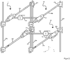
- Figure 1 shows a 3D printer according to the prior art, while a preferred embodiment of the 3D printer according to the invention in Figure 2 is shown.
- all information such as the X, Y or Z direction or XY plane relate to a Cartesian coordinate system (unless otherwise stated).
- the 3D printer (1) according to the invention differs according to Figure 2 from a corresponding 3D printer according to the prior art Figure 1 ostensibly that an additional counterweight (30) is present in the 3D printer (1) according to the invention, which counterweight is controlled by a second drive unit (40).
- the counterweight (30) and the second drive unit (40) are connected to one another using linkages in such a way that they jointly form a second XY plane (60). In other words, this means that the counterweight (30) is moved within the second XY plane (60) during the 3D printing process.
- the weight of the counterweight (30) can be fixed or variable, for example the weight of the counterweight (30) can be adjusted or controlled via a hydraulic filling mechanism.
- the first drive unit comprises a motor (21) for controlling the print head (10) in the X direction and two motors (22a and 22b) for controlling the print head (10) in the Y direction (in each case based on a Cartesian coordinate system) .
- the linkage in the XY direction (24a to 24c) is preferably made of aluminum.
- the motors and the print head are fastened via the linkage, which enables the print head (10) to move in the first XY plane (50) during the 3D printing process within the housing (2) of the 3D printer (1).
- the linkage is represented by the reference numerals (24d to 24g).
- additional motors (23a to 23d) may be present, which move the entire structure which forms the first XY plane (50), i.e. the print head (10), the first drive unit (20) and the associated motors and the like Allow linkage in Z direction.
- this is only an optional embodiment both in the prior art and in the context of the present invention.
- the second XY plane (60) already described above which is formed by the counterweight (30) and the associated second drive unit (40) and the associated linkage, is likewise connected to the linkage (24d to 24g) formed in the Z direction.
- four additional motors (43a to 43d) are optionally included, which make it possible for the second XY plane (formed by the counterweight (30) and the second drive unit (40) in conjunction with the associated linkage (44a to 44c) 60) to move in the Z direction.
- the second drive unit (40) is formed by two motors (42a) and (42b) for controlling the counterweight in the Y direction.
- the counterweight (30) also contains a further motor (41) (not shown in the application), which enables the counterweight (30) to be controlled in the X direction.
- the counterweight (30) is in a mirror image position to the print head (10).
- the mirror image is obtained in this embodiment in that there is a point reflection, the mirror point lying in a fourth XY plane (75), which is halfway in the Z direction between the first XY plane (50) and the second XY Level (60) is located within the housing (2) of the 3D printer (1).
Landscapes
- Chemical & Material Sciences (AREA)
- Engineering & Computer Science (AREA)
- Materials Engineering (AREA)
- Manufacturing & Machinery (AREA)
- Physics & Mathematics (AREA)
- Mechanical Engineering (AREA)
- Optics & Photonics (AREA)
Priority Applications (1)
| Application Number | Priority Date | Filing Date | Title |
|---|---|---|---|
| EP18201045.4A EP3640008A1 (fr) | 2018-10-17 | 2018-10-17 | Imprimantes tridimensionnelle dans laquelle un mécanisme mobile sert à réduire les vibrations |
Applications Claiming Priority (1)
| Application Number | Priority Date | Filing Date | Title |
|---|---|---|---|
| EP18201045.4A EP3640008A1 (fr) | 2018-10-17 | 2018-10-17 | Imprimantes tridimensionnelle dans laquelle un mécanisme mobile sert à réduire les vibrations |
Publications (1)
| Publication Number | Publication Date |
|---|---|
| EP3640008A1 true EP3640008A1 (fr) | 2020-04-22 |
Family
ID=63965078
Family Applications (1)
| Application Number | Title | Priority Date | Filing Date |
|---|---|---|---|
| EP18201045.4A Ceased EP3640008A1 (fr) | 2018-10-17 | 2018-10-17 | Imprimantes tridimensionnelle dans laquelle un mécanisme mobile sert à réduire les vibrations |
Country Status (1)
| Country | Link |
|---|---|
| EP (1) | EP3640008A1 (fr) |
Cited By (1)
| Publication number | Priority date | Publication date | Assignee | Title |
|---|---|---|---|---|
| CN112497734A (zh) * | 2020-10-10 | 2021-03-16 | 合肥海闻自动化设备有限公司 | 一种三维增材打印机打印范围控制调节装置 |
Citations (8)
| Publication number | Priority date | Publication date | Assignee | Title |
|---|---|---|---|---|
| DE69033809T2 (de) | 1989-10-30 | 2002-04-25 | Stratasys Inc | Gerät und Verfahren zum Erzeugen dreidimensionaler Objekte |
| WO2017009190A1 (fr) | 2015-07-14 | 2017-01-19 | Basf Se | Filaments à base de matériau d'âme revêtu |
| DE102015111677A1 (de) | 2015-07-17 | 2017-01-19 | BigRep GmbH | 3D-Druckvorrichtung mit rotierbarer Isolierung |
| CN106956427A (zh) * | 2016-03-14 | 2017-07-18 | 昆山博力迈三维打印科技有限公司 | 一种大型材料挤压式3d打印机 |
| CN107303726A (zh) * | 2016-04-23 | 2017-10-31 | 罗天珍 | Fdm3d打印机的直线配重法及其打印机 |
| US20180056608A1 (en) | 2016-09-01 | 2018-03-01 | Stratasys, Inc. | 3d printer with coupling for attaching print head and additional equipment to head carriage |
| WO2018097954A1 (fr) | 2016-11-23 | 2018-05-31 | 3D Systems, Inc. | Imprimante tridimensionnelle ayant une compensation de pression pour des contraintes induites |
| WO2018125555A1 (fr) | 2016-12-29 | 2018-07-05 | 3D Systems, Inc. | Système d'impression en trois dimensions doté d'un système de manipulation de poudre efficace |
-
2018
- 2018-10-17 EP EP18201045.4A patent/EP3640008A1/fr not_active Ceased
Patent Citations (8)
| Publication number | Priority date | Publication date | Assignee | Title |
|---|---|---|---|---|
| DE69033809T2 (de) | 1989-10-30 | 2002-04-25 | Stratasys Inc | Gerät und Verfahren zum Erzeugen dreidimensionaler Objekte |
| WO2017009190A1 (fr) | 2015-07-14 | 2017-01-19 | Basf Se | Filaments à base de matériau d'âme revêtu |
| DE102015111677A1 (de) | 2015-07-17 | 2017-01-19 | BigRep GmbH | 3D-Druckvorrichtung mit rotierbarer Isolierung |
| CN106956427A (zh) * | 2016-03-14 | 2017-07-18 | 昆山博力迈三维打印科技有限公司 | 一种大型材料挤压式3d打印机 |
| CN107303726A (zh) * | 2016-04-23 | 2017-10-31 | 罗天珍 | Fdm3d打印机的直线配重法及其打印机 |
| US20180056608A1 (en) | 2016-09-01 | 2018-03-01 | Stratasys, Inc. | 3d printer with coupling for attaching print head and additional equipment to head carriage |
| WO2018097954A1 (fr) | 2016-11-23 | 2018-05-31 | 3D Systems, Inc. | Imprimante tridimensionnelle ayant une compensation de pression pour des contraintes induites |
| WO2018125555A1 (fr) | 2016-12-29 | 2018-07-05 | 3D Systems, Inc. | Système d'impression en trois dimensions doté d'un système de manipulation de poudre efficace |
Cited By (2)
| Publication number | Priority date | Publication date | Assignee | Title |
|---|---|---|---|---|
| CN112497734A (zh) * | 2020-10-10 | 2021-03-16 | 合肥海闻自动化设备有限公司 | 一种三维增材打印机打印范围控制调节装置 |
| CN112497734B (zh) * | 2020-10-10 | 2024-01-12 | 合肥海闻自动化设备有限公司 | 一种三维增材打印机打印范围控制调节装置 |
Similar Documents
| Publication | Publication Date | Title |
|---|---|---|
| EP3475018B1 (fr) | Procédé permettant de vider les cavités remplies de poudre d'une pièce et appareil pour la mise en oeuvre de ce procédé | |
| DE102007006478B4 (de) | Vorrichtung und Verfahren zum Zuführen von sinterbarem Pulver auf eine Auftragsstelle einer Lasersintereinrichtung | |
| EP3131740A1 (fr) | Unité de commande, dispositif et procédé de fabrication d'un objet en trois dimensions | |
| EP2705942B1 (fr) | Procédé et dispositif pour la fabrication d'objets tridimensionnels dotés de parties non soutenues et/ou en surplomb | |
| DE102016209933A1 (de) | Vorrichtung und Verfahren zum generativen Herstellen eines dreidimensionalen Objekts | |
| DE102017213720A1 (de) | Optimiertes Segmentierungsverfahren | |
| EP3585592B1 (fr) | Homogénéisation de l'apport énergétique | |
| EP3579998B1 (fr) | Augmentation de la qualité de surface | |
| EP3642038B1 (fr) | Dispositif et procédé de fabrication générative d'un objet tridimensionnel avec systeme de levage | |
| DE102018202506A1 (de) | Additives Herstellverfahren mit kontrollierter Verfestigung und zugehörige Vorrichtung | |
| WO2017207127A1 (fr) | Procédé et système de fabrication additive d'un objet | |
| WO2017153187A1 (fr) | Procédé de construction par couches génératif présentant une résolution améliorée des détails et dispositif pour sa réalisation | |
| EP3388171B1 (fr) | Procédé et dispositif de fabrication permettant la construction en couches d'un corps moulé défini à l'aide des données de description géométrique | |
| DE102016121648A1 (de) | Vorrichtung zur additiven Herstellung dreidimensionaler Objekte | |
| EP3640008A1 (fr) | Imprimantes tridimensionnelle dans laquelle un mécanisme mobile sert à réduire les vibrations | |
| WO2017097287A1 (fr) | Dispositif et procédé de fabrication d'un corps moulé métallique tridimensionnel | |
| AT523693B1 (de) | Verfahren zur Herstellung eines dreidimensionalen Bauteils | |
| WO2022049161A1 (fr) | Procédé de fabrication additive | |
| EP4164866A1 (fr) | Procédé et dispositifs de fabrication de pièces moulées tridimensionnelles | |
| EP3944911A1 (fr) | Système doté d'un dispositif d'impression 3d et mode de fonctionnement d'un tel système | |
| EP3722023A1 (fr) | Lutte contre de l'étirage des composants imprimés de manière tridimensionnelle | |
| WO2023213690A1 (fr) | Procédé et dispositif de génération de données de commande d'irradiation pour un dispositif de fabrication additive d'un composant | |
| DE102017128913A1 (de) | Einrichtung und Verfahren zur additiven Fertigung von Gegenständen | |
| DE102015225012A1 (de) | Verfahren und Vorrichtung zur Prüfung eines Eingangsdatensatzes einer generativen Schichtbauvorrichtung | |
| DE19900963A1 (de) | Verfahren zum Herstellen dreidimensionaler Strukturen |
Legal Events
| Date | Code | Title | Description |
|---|---|---|---|
| PUAI | Public reference made under article 153(3) epc to a published international application that has entered the european phase |
Free format text: ORIGINAL CODE: 0009012 |
|
| AK | Designated contracting states |
Kind code of ref document: A1 Designated state(s): AL AT BE BG CH CY CZ DE DK EE ES FI FR GB GR HR HU IE IS IT LI LT LU LV MC MK MT NL NO PL PT RO RS SE SI SK SM TR |
|
| AX | Request for extension of the european patent |
Extension state: BA ME |
|
| STAA | Information on the status of an ep patent application or granted ep patent |
Free format text: STATUS: THE APPLICATION HAS BEEN REFUSED |
|
| 18R | Application refused |
Effective date: 20201011 |