EP3639942A1 - Pressmaschine mit sensorsystem zur automatisierten erkennung einer pressbackenanordnung - Google Patents
Pressmaschine mit sensorsystem zur automatisierten erkennung einer pressbackenanordnung Download PDFInfo
- Publication number
- EP3639942A1 EP3639942A1 EP18201502.4A EP18201502A EP3639942A1 EP 3639942 A1 EP3639942 A1 EP 3639942A1 EP 18201502 A EP18201502 A EP 18201502A EP 3639942 A1 EP3639942 A1 EP 3639942A1
- Authority
- EP
- European Patent Office
- Prior art keywords
- press
- workpiece
- press machine
- jaw arrangement
- sensor system
- Prior art date
- Legal status (The legal status is an assumption and is not a legal conclusion. Google has not performed a legal analysis and makes no representation as to the accuracy of the status listed.)
- Granted
Links
Images


Classifications
-
- B—PERFORMING OPERATIONS; TRANSPORTING
- B21—MECHANICAL METAL-WORKING WITHOUT ESSENTIALLY REMOVING MATERIAL; PUNCHING METAL
- B21D—WORKING OR PROCESSING OF SHEET METAL OR METAL TUBES, RODS OR PROFILES WITHOUT ESSENTIALLY REMOVING MATERIAL; PUNCHING METAL
- B21D39/00—Application of procedures in order to connect objects or parts, e.g. coating with sheet metal otherwise than by plating; Tube expanders
- B21D39/04—Application of procedures in order to connect objects or parts, e.g. coating with sheet metal otherwise than by plating; Tube expanders of tubes with tubes; of tubes with rods
-
- B—PERFORMING OPERATIONS; TRANSPORTING
- B25—HAND TOOLS; PORTABLE POWER-DRIVEN TOOLS; MANIPULATORS
- B25B—TOOLS OR BENCH DEVICES NOT OTHERWISE PROVIDED FOR, FOR FASTENING, CONNECTING, DISENGAGING, OR HOLDING
- B25B27/00—Hand tools, specially adapted for fitting together or separating parts or objects whether or not involving some deformation, not otherwise provided for
- B25B27/02—Hand tools, specially adapted for fitting together or separating parts or objects whether or not involving some deformation, not otherwise provided for for connecting objects by press fit or detaching same
- B25B27/10—Hand tools, specially adapted for fitting together or separating parts or objects whether or not involving some deformation, not otherwise provided for for connecting objects by press fit or detaching same inserting fittings into hoses
-
- H—ELECTRICITY
- H01—ELECTRIC ELEMENTS
- H01R—ELECTRICALLY-CONDUCTIVE CONNECTIONS; STRUCTURAL ASSOCIATIONS OF A PLURALITY OF MUTUALLY-INSULATED ELECTRICAL CONNECTING ELEMENTS; COUPLING DEVICES; CURRENT COLLECTORS
- H01R43/00—Apparatus or processes specially adapted for manufacturing, assembling, maintaining, or repairing of line connectors or current collectors or for joining electric conductors
- H01R43/04—Apparatus or processes specially adapted for manufacturing, assembling, maintaining, or repairing of line connectors or current collectors or for joining electric conductors for forming connections by deformation, e.g. crimping tool
- H01R43/042—Hand tools for crimping
- H01R43/0428—Power-driven hand crimping tools
-
- B—PERFORMING OPERATIONS; TRANSPORTING
- B21—MECHANICAL METAL-WORKING WITHOUT ESSENTIALLY REMOVING MATERIAL; PUNCHING METAL
- B21D—WORKING OR PROCESSING OF SHEET METAL OR METAL TUBES, RODS OR PROFILES WITHOUT ESSENTIALLY REMOVING MATERIAL; PUNCHING METAL
- B21D39/00—Application of procedures in order to connect objects or parts, e.g. coating with sheet metal otherwise than by plating; Tube expanders
- B21D39/04—Application of procedures in order to connect objects or parts, e.g. coating with sheet metal otherwise than by plating; Tube expanders of tubes with tubes; of tubes with rods
- B21D39/048—Application of procedures in order to connect objects or parts, e.g. coating with sheet metal otherwise than by plating; Tube expanders of tubes with tubes; of tubes with rods using presses for radially crimping tubular elements
-
- B—PERFORMING OPERATIONS; TRANSPORTING
- B25—HAND TOOLS; PORTABLE POWER-DRIVEN TOOLS; MANIPULATORS
- B25B—TOOLS OR BENCH DEVICES NOT OTHERWISE PROVIDED FOR, FOR FASTENING, CONNECTING, DISENGAGING, OR HOLDING
- B25B27/00—Hand tools, specially adapted for fitting together or separating parts or objects whether or not involving some deformation, not otherwise provided for
- B25B27/14—Hand tools, specially adapted for fitting together or separating parts or objects whether or not involving some deformation, not otherwise provided for for assembling objects other than by press fit or detaching same
- B25B27/146—Clip clamping hand tools
-
- H—ELECTRICITY
- H01—ELECTRIC ELEMENTS
- H01R—ELECTRICALLY-CONDUCTIVE CONNECTIONS; STRUCTURAL ASSOCIATIONS OF A PLURALITY OF MUTUALLY-INSULATED ELECTRICAL CONNECTING ELEMENTS; COUPLING DEVICES; CURRENT COLLECTORS
- H01R43/00—Apparatus or processes specially adapted for manufacturing, assembling, maintaining, or repairing of line connectors or current collectors or for joining electric conductors
- H01R43/04—Apparatus or processes specially adapted for manufacturing, assembling, maintaining, or repairing of line connectors or current collectors or for joining electric conductors for forming connections by deformation, e.g. crimping tool
- H01R43/048—Crimping apparatus or processes
Definitions
- the present invention relates to a press machine for plastically deforming a tubular workpiece, in particular a fitting.
- the invention further relates to a method for operating such a press machine, a press jaw arrangement for coupling to a press machine, and also a tubular workpiece, in particular fitting.
- pipes can be soldered or welded together. It is also known to insert the end of a small pipe into a pipe end of a larger pipe and then to press both pipe ends together.
- the pressing is carried out using a (press) fitting.
- press machines such as pipe press machines
- a fitting can be configured, for example, as a pipe fitting, which can be used as a connecting piece of a pipe.
- a fitting can consist of different materials, for example copper, aluminum, plastic, composite and / or (stainless steel).
- a (pipe) press machine can press jaws made of metals such as steel, aluminum or the like. include, which may be interchangeable. Furthermore, the pressing machine can comprise an exchangeable pressing tongs which have the pressing jaws. Other press jaw assemblies, including press jaws, are also known. By means of the press jaws or the press jaw arrangement, a force can be exerted on the fitting in order to deform it plastically in such a way that the fitting is as possible is tight, tight and tight against a pipe. When using such a press machine, the press jaws can be pressed together in order to press a fitting arranged in between over a pipe. The press machine can be hand-held and operated by a drive. Electrical and / or hydraulic drives are typically used.
- the press jaws or the press jaw arrangement are typically workpiece-specific.
- other pressing jaws / pressing jaw arrangements are used for pressing metal fittings, such as copper or (stainless steel) fittings, than when pressing plastic fittings.
- the press machine can be adapted to different workpieces, in particular fittings, by exchanging the press jaws / press jaw arrangement.
- the pressing is always carried out using the maximum pressing force, irrespective of the actually used pressing jaws or the used pressing jaw arrangement and / or the fittings used.
- this can be disadvantageous since, for example, plastic fittings can be pressed with a much lower pressing force than metal fittings. Applying the maximum pressing force thus leads to an unnecessary waste of energy.
- each type of press jaw or press jaw arrangement used has its characteristic press characteristics.
- the pressing characteristics can depend, for example, on the transmission ratio of the pressing jaw arrangement, the material of the pressing jaws and the workpiece to be pressed.
- a workpiece such as a steel fitting
- a plastic fitting for example, in order to guarantee the best possible form fit and a long durability of the pressed fitting.
- the present invention is therefore based on the object of achieving the most optimal and material-friendly pressing of a fitting with a pipe.
- an improved (pipe) press machine is to be provided, which enables such pressing.
- the present invention relates to a press machine for plastically deforming a tubular workpiece.
- the tubular workpiece can be a fitting, for example, and pressed to connect two pipes.
- the fitting can consist, for example, at least partially of copper, aluminum, plastic, composite and / or (stainless steel).
- the press machine in turn can be set up to plastically deform such a tubular workpiece, such as a fitting, for example, that it is connected to a piece of pipeline arranged in the fitting.
- a (compression) pressing can be carried out by means of the pressing machine in order to connect a fitting with a pipe in a non-detachable manner and / or in a non-positive manner.
- the fitting can be specified, for example, according to the standard DIN EN 1254-7.
- the press machine further comprises a press jaw receptacle for coupling a press jaw arrangement to the press machine.
- the press jaw receptacle couples to the press jaw arrangement in such a way that the press machine can drive press jaws of the press jaw arrangement.
- the coupling takes place via at least one coupling bolt.
- the press jaws of the press jaw arrangement can be arranged to be movable relative to one another and, for example, can be closed and also moved apart, so that in the moved-apart state, for example, a tubular workpiece, such as a fitting, can be arranged between the press jaws.
- the press jaws of the press jaw arrangement can be exchangeable. Different press jaw arrangements and / or press jaws can be designed for different tasks, such as pressing, crimping, or cutting.
- a press jaw arrangement typically comprises at least two press jaws.
- the press machine further comprises a drive, which is set up to drive the press jaw arrangement in order to apply a force to the workpiece.
- the drive can comprise an electric motor, a pneumatic and / or a hydraulic drive unit and a gear.
- the press jaws of the press jaw arrangement can be moved relative to one another and driven, for example, into the closed state.
- the drive can at least partially apply the force necessary to deform the tubular workpiece, for example to connect a fitting to a pipe section.
- the drive can be connected to the press jaw arrangement directly or via a gear in order to transmit the driving force to the press jaw arrangement and the press packs.
- the force acting on the press jaws or the press jaw arrangement can be variably adjusted, for example by correspondingly varying motor parameters or other parameters (such as gear settings).
- the press machine comprises a sensor system which is set up to identify a press jaw arrangement and to provide corresponding sensor data.
- the sensor system can be set up to recognize an individual press jaw arrangement, or also to recognize a press jaw arrangement according to its type.
- the sensor system can include detection means (e.g. a sensor) as an interface to the press jaw arrangement, and corresponding evaluation means, which can include a processor and / or memory with the appropriate program code.
- the detection means can be provided separately from the evaluation means on the press machine.
- the sensor system can be supplied via an energy source arranged on the press machine, which can also feed the drive or the electric motor, for example.
- the sensor system can also be activated by a user / operator using a button in order to carry out the identification.
- the sensor system can be set up to recognize an exchange and in particular the coupling of a press jaw arrangement to the press jaw receptacle and to carry out the identification after recognizing the exchange or the coupling.
- the identification therefore does not necessarily mean that an individual press jaw arrangement is identified as an individual press jaw arrangement. Rather, it suffices that a press jaw arrangement is identified or recognized as being different from another press jaw arrangement.
- the press jaw arrangement can be classified, for example, on the basis of its model number. In one example it can thus be recognized that a press jaw arrangement for pressing stainless steel fittings with a diameter of 15 mm is present and / or is coupled. Resulting sensor data can characterize the identified press jaw arrangement.
- the press machine includes a controller that is set up to control the drive based on the sensor data.
- the drive is controlled accordingly.
- the press jaw arrangement can, for example, be driven differently by the drive in order ultimately to optimally deform the workpiece.
- the present invention thus makes it possible to carry out the shaping as a function of the coupled pressing jaw arrangement.
- an individual pressing force can be applied by means of the drive in order to achieve an optimal and gentle deformation of the workpiece.
- the use of the sensor system allows the press jaw arrangement to be automatically identified and corresponding data to be passed on to the drive, so that the user or operator of the press machine does not have to make any entries himself and accordingly is not additionally burdened. This can reduce the risk of incorrect operation.
- the press machine preferably comprises a storage medium with a database.
- the database preferably includes, for a plurality of press jaw arrangements, specific control parameters for controlling the press machine. Furthermore, the controller can then control the drive according to the at least one specific control parameter. According to the identification of the press jaw arrangement, corresponding control parameters can thus be loaded from the memory or from the database and used to operate the drive. For example, control parameters for a press jaw arrangement for stainless steel fittings and different control parameters for a press jaw arrangement for copper fittings can be stored in the database. Depending on whether a pressing jaw arrangement for stainless steel or copper fittings has been identified by means of the sensor system, the corresponding control parameters can be loaded from the database and used by the control to control the pressing machine and ultimately the drive.
- Corresponding control parameters can be stored in the database for different characteristics of the press jaw arrangements (for example transmission ratio, type of press jaws, size of the workpiece to be pressed, material of the workpiece to be pressed, and / or shape of the workpiece to be pressed) to enable optimal pressing or deformation of the respective workpiece.
- the database can be accessed via a (wired or wireless) interface, for example to update the content of the database.
- the control parameters particularly preferably include press parameters, which preferably include a maximum press force, a press speed, press travel and / or a press duration.
- press parameters which preferably include a maximum press force, a press speed, press travel and / or a press duration.
- certain press forces, press speeds, press paths and / or press durations can be specified, for example, which are to be used by the press machine for pressing or deforming the fitting with the pipe section, for example.
- These parameters can be specified, for example, in the form of a pressing curve, which specifies a time course of the pressing force, pressing path and / or pressing speed.
- the person skilled in the art understands, depending on the intended use of the press machine, to store corresponding control parameters in the database.
- control parameters can in particular include drive parameters, which in particular include a drive speed, drive power and / or an oil pressure.
- drive parameters can thus be stored in the database, which can be loaded based on the identified press jaw arrangement in order to ultimately deform the workpiece.
- the pressing parameters or drive parameters can include motor and / or transmission parameters which can regulate the power transmission from the drive to the pressing jaws.
- the sensor system can comprise at least one optical sensor, a contact-based sensor, an inductive sensor and / or capacitive sensor, wherein the sensor system can in particular be set up to read an RFID and / or NFC transponder.
- the sensor system can alternatively or additionally be set up to read a bar code or a QR code.
- the sensor system can comprise a Bluetooth module, which is set up to read out a corresponding Bluetooth module.
- a Contact-based sensor can include an electrical contact that comes into contact with a corresponding electrical contact of the pressing jaw / pressing jaw arrangement in order to identify the pressing jaw / pressing jaw arrangement.
- the use of an inductive and / or capacitive sensor enables reliable identification, since inductive and / or capacitive sensors are less susceptible to contamination, such as optical or contact-based sensors.
- the RFID and / or NFC transponder or the corresponding Bluetooth module can have an identifier that is read out during identification. This identifier is characteristic of the type of press jaw arrangement or for an individual press jaw arrangement and can include, for example, a serial number and / or a type number.
- the control parameters can then be determined on the basis of the identifier read out and the database.
- the RFID and / or NFC transponder or the corresponding Bluetooth module can include the control parameters themselves. These can then be read out during identification and passed on to the controller.
- the press jaw arrangement carries the necessary control parameters in the RFID and / or NFC transponder assigned to it or in a corresponding Bluetooth module.
- RFID (English: radio frequency identification) enables the identification of the press jaw arrangement by means of electromagnetic waves.
- the press jaw arrangement can be identified automatically and without contact using RFID technology.
- An RFID reader (sensor) arranged on the press machine can read out the identifier and / or control parameters, which can be provided by a corresponding RFID transponder of the press jaw arrangement.
- An RFID transponder can be read out without additional energy being provided.
- the press jaw arrangement can thus be designed passively and does not require an additional interface or source for providing electrical energy.
- NFC technology or near field communication is an international transmission standard based on RFID technology for the contactless exchange of data via electromagnetic induction or capacitive transmission.
- the communication between the corresponding NFC participants can be active-passive or also active-active.
- the active part ie the part that is supplied with electrical energy, is preferably provided in the press machine, the passive part on the press jaw arrangement.
- the press jaw arrangement can thus be designed passively and does not require an additional interface or source for providing electrical energy.
- Bluetooth communication enables data transmission between devices over a short distance using radio technology. Communication takes place using an appropriately developed industry standard, for example in accordance with the IEEE 802.15.1 standard.
- a first reading range of the sensor system can be limited and be at most 0.3 m, preferably at most 0.2 m and most preferably at most 0.1 m.
- the first reading range of the sensor system can be selected such that only a coupled press jaw arrangement can be identified. Limiting the first reading range prevents an incorrect press jaw arrangement located in the vicinity of the press machine from being inadvertently identified.
- the press machine is provided together with a plurality of press jaw arrangements in a transport case or on a workbench. When the press machine is started up, only the coupled or the press jaw arrangement to be coupled should be identified. This can be ensured by limiting the first reading range.
- the sensor system can be set up to identify a workpiece, the storage medium comprising a database which comprises at least one specific control parameter for a plurality of workpieces, the controller being set up to control the drive according to the at least one specific control parameter.
- the drive is controlled accordingly depending on the workpiece identified.
- the press jaws can be driven differently by the drive, for example, in order to ultimately optimally deform the workpiece.
- Both the type of workpiece and the type of press jaw arrangement can be taken into account when selecting the control parameters. In particular, it can be checked whether the identified pressing jaw arrangement matches the workpiece to be pressed. If this is not the case, an alarm can be triggered issued in order to avoid faulty pressing and / or damage to the press machine.
- the control parameters can also be adapted to the identified workpiece, thus avoiding excessive pressing.
- a press jaw arrangement for pressing stainless steel fittings is coupled to the press machine and the workpiece to be pressed is a copper fitting
- an excessive press force would be applied if only the type of press jaw arrangement was taken into account.
- the type of workpiece is also recognized, the pressing force can be reduced accordingly and the workpiece can be pressed with the supposedly unsuitable pressing jaw arrangement - but with a reduced pressing force.
- the present invention thus allows the deformation to be carried out as a function of the object to be deformed and the press jaw arrangement used.
- an individual pressing force can be applied by means of the drive in order to achieve an optimal and gentle deformation without damaging the workpiece or the pressing machine.
- a second reading range for identifying the workpiece can preferably be in the range from 0 meters to 5 meters, more preferably in the range from 0.01 meters to 2 meters, further preferably in the range from 0.02 meters to 1 meter and further preferably in the range from 0 .05 meters to 0.5 meters.
- the sensor system can therefore only identify workpieces that are within the second reading range. This enables only those workpieces that are actually to be deformed to be identified. This at least partially prevents accidental identification of workpieces that are far away and cannot be deformed.
- the first and the second reading range can be different.
- the sensor system is preferably set up to identify features of characteristic features of the workpiece, in particular of characteristic geometric features of the press jaw arrangement and / or of a workpiece. For example, a shape and / or size of at least part of the press jaw arrangement and / or the workpiece can be recognized by means of the sensor system. On the basis of these characteristic features, the pressing jaw arrangement and / or the workpiece can be identified, at least according to their type, and the drive can then be controlled accordingly to optimally deform the workpiece.
- the sensor system comprises a sensor such as a camera, an optical scanner, an RFID reader, an NFC reader and / or a Bluetooth module for identifying the workpiece.
- the same sensor or different sensors or sensor types can be used to identify the workpiece and press jaw arrangement.
- the camera can be an optical camera, which can have sufficient resolution and quality to identify the workpiece, at least according to its type. For example, a fitting with a diameter of 15 mm can be identified using the camera. Color values can also be used to infer the material of the workpiece.
- the optical scanner the RFID reader, the NFC reader and / or the Bluetooth module, data or identifications can be recognized, which can be provided by the workpiece itself or the press jaw arrangement, for example, and allow the workpiece to be identified .
- the optical scanner can recognize a barcode or QR code that is arranged on the workpiece.
- a lamp can also be provided on the press machine, which can at least partially illuminate or illuminate the area that can be detected by the camera or by the scanner.
- the sensor system is preferably set up to recognize a barcode on the workpiece, a QR code on the workpiece, an identifier in an RFID transponder on the workpiece, an identifier in an NFC transponder on the workpiece, and / or an identifier in one Bluetooth module on the workpiece.
- the person skilled in the art understands that the workpiece can be equipped with corresponding codes or transponders or modules in order to provide the press machine with appropriate data for identifying the workpiece, at least according to its type.
- the senor of the sensor system can be arranged directly on the press jaw holder.
- the sensor is at least partially covered by an element of the press machine in a first configuration of the press machine, and is released by the element in a second configuration of the press machine.
- a sensor of the sensor system can be covered by part of the housing of the press machine, whereby the sensor can be protected against dirt or other environmental influences.
- the press jaws are moved apart or opened, which can correspond to the second configuration, the sensor is (at least partially) released or exposed.
- the press jaw arrangement and / or the workpiece can now be identified by means of the sensor system.
- the press jaws are moved towards one another or brought into the first configuration, as a result of which the sensor can again be at least partially covered by part of the housing. This also ensures that the identification by means of the sensor system only takes place if the workpiece is to be deformed. This prevents the wrong identification of a workpiece that is nearby (e.g. lying on a workbench).
- the press jaws of the press jaw arrangement and particularly preferably the entire press jaw arrangement are preferably free of the sensor system.
- no elements of the sensor system are arranged on the press jaws or the press jaw arrangement.
- the sensor system can thus, for example, be arranged exclusively on or in a hand part of the press machine. This enables the press jaws or the press jaw arrangement to be easily exchanged.
- the sensor system is at least partially arranged on the press jaws or the press jaw arrangement, in particular in a depression of the press jaws (for example to protect the sensor system).
- the sensor system can be connected to the motor of the press machine via a coupling interface.
- the sensor system is preferably at least partially arranged in a housing of the press machine. If the sensor system is set up to read an RFID and / or NFC transponder, or if it comprises a Bluetooth module, the sensor system can be arranged entirely within the housing of the press machine.
- the housing of the press machine is at least partially permeable to the readout data.
- the housing material can comprise glass, ceramic, plastics or composites which are at least partially transparent to electromagnetic radiation.
- the housing can have suitable cutouts to enable reading. With this arrangement, the sensor system can be protected against contamination or other environmental influences, since it is at least partially shielded by the housing of the press machine.
- the press jaw arrangement can at least partially cover the sensor of the sensor system when the press jaw arrangement is coupled to the press jaw receptacle, the sensor being at least partially uncovered when no press jaw arrangement is coupled to the press jaw receptacle.
- the sensor system or the sensor can be protected against contamination or other environmental influences.
- the reading accuracy of the sensor system can be increased since the sensor system or the sensor of the sensor system is set up directly adjacent to the coupled pressing jaw receptacle and is not covered by other parts, such as a housing part. This means that a very small maximum first reading range can be achieved and the risk of incorrect identification of adjacent, non-coupled press jaw receptacles can be reduced.
- the press machine preferably comprises a log memory set up for storing the sensor data and control data.
- the coupling process and / or the deformation process can be made traceable. All or some of the data relating to the coupling process and / or the deformation process can be stored in the log memory, for example to enable quality monitoring of individual deformations.
- the log memory can be accessed via a (wireless or wired) interface to read out the corresponding data.
- the present invention further relates to a method for operating a press machine according to the above statements, for plastically deforming a tubular workpiece, such as a fitting.
- the method comprises the following steps: coupling a press jaw arrangement to the press jaw holder of the press machine; Identifying the press jaw arrangement by means of the sensor system and preferably identifying the workpiece; Gripping the workpiece with the coupled press jaw assembly; Controlling the press machine according to the identified press jaw arrangement and preferably according to the identified workpiece, in order to apply a force by means of the press jaw arrangement to the surface of the gripped workpiece in order to plastically deform the workpiece.
- the pressing jaw arrangement can be identified after the coupling or before the coupling, in particular during the coupling.
- the drive of the press machine can be controlled accordingly. It can depend a reduced or increased pressing force, pressing duration and / or pressing speed can be set from the identifying step, depending on which pressing jaw arrangement or which workpiece type has been identified.
- the method steps of identifying, gripping and / or controlling can be implemented in a computer program, wherein the computer program can cause a corresponding press machine system to carry out the respective steps.
- the present invention further relates to a press jaw arrangement for coupling to a press machine for plastically deforming a tubular workpiece, in particular a fitting.
- this press jaw arrangement can be coupled to a press machine according to the above statements.
- the press jaw arrangement comprises a marking which is set up to be identified by the sensor system of the press machine, the marking preferably comprising an RFID transponder or an NFC transponder.
- the marking is preferably arranged in a depression of the press jaw arrangement in order to protect it from dirt, damage and other environmental influences.
- the depression can be sealed.
- the depression, including the marking can be sealed with a plastic, such as an epoxy resin, glass or ceramic.
- the sealing material can completely enclose and / or cover the marking.
- the present invention further relates to a tubular workpiece, in particular fitting, which is set up for plastic deformation by a press machine.
- the tubular workpiece can be deformed for example by a press machine according to the above statements.
- the workpiece, in particular fitting can be configured in accordance with the above explanations and can consist of copper, plastic, composite, and / or (stainless steel).
- the tubular workpiece comprises a means which is set up to provide an identifier for identifying the workpiece.
- the means can be configured, for example, as a barcode or QR code.
- the means can comprise a transponder, in particular an RFID or NFC transponder, which is set up to provide the identifier.
- a press machine system 1 which comprises a press machine 10 and a press jaw arrangement 20 according to an embodiment of the present invention as well.
- the press machine 10 comprises a hand part 11, which can be guided by an operator or user.
- the pressing jaw arrangement 20 can be detachably coupled to the hand part 11.
- the press jaw arrangement 20 comprises two press jaws 21a, 21b by means of which a workpiece (fitting) can be gripped and plastically deformed.
- a drive 14, such as an electric motor with a transmission, is provided in the hand part 11, which drive the press jaw arrangement 20 via a coupling interface and can ultimately move the press jaws 21a, 21b in order to deform the fitting.
- an operator can actuate a corresponding actuation lever 13: By actuating the lever 13 accordingly, the press jaws 21a, 21b are first moved apart to grip a fitting and then pressed together to deform the fitting.
- the coupling of the pressing jaw arrangement 20 to the pressing machine 10 takes place via the pressing jaw receptacle 12, which can for example comprise a bolt.
- a sensor system 40 (cf. Fig. 4 ) provided.
- the sensor system comprises an inductive and / or capacitive sensor and is in particular set up for reading out an RFID and / or NFC transponder 22.
- the sensor system 40 By actuating the lever 13 to move the pressing jaws 21a, 21b apart to grip a fitting, the sensor system 40 is activated.
- the sensor system 40 can be activated when a press jaw arrangement 20 is coupled to the press jaw receptacle 12.
- the sensor system 40 can for example recognize and read out an identifier from a corresponding press jaw arrangement 20.
- the identifier can be stored in a transponder 22.
- the transponder can have stored control data that can be read out by the sensor system 40.
- the pressing jaw arrangement 20 can be identified by means of the sensor system 40.
- the sensor system 40 can identify a workpiece type.
- the drive 14 is driven in order to exert a force on the fitting arranged between the press jaws 21a, 21b.
- the drive 14 is controlled depending on which press jaw arrangement 20 or which type of workpiece has been identified.
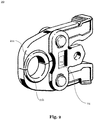
- a press jaw assembly 20 with press jaws 21a, 21b is shown in accordance with an embodiment of the present invention.
- the press jaw arrangement can be detachably coupled to a press jaw receptacle 12 of a press machine 10.
- a transponder 22 (for example an RFID or NFC transponder) is arranged in a recess 24. If the press jaw arrangement 20 is coupled to the press jaw receptacle 12 of a press machine 10, the sensor system 40 and in particular a sensor of the sensor system is at least partially covered.
- FIG. 3 A possible embodiment of a tubular workpiece according to an embodiment of the present invention is shown.
- the workpiece shown is designed in the form of a fitting 30.
- the fitting 30 comprise a means 32 for providing an identifier for identifying the respective fitting 30, for example to a press machine 10 according to FIG Figure 1 .
- That in the Figure 3 Fitting 30 shown comprises an RFID transponder 32, on which at least one identifier is stored.
- the identifier characterizes the fitting 30 at least according to its type.
- the identifier stored on the RFID transponder 32 of the fitting 30 can be read out in order to identify the fitting 30.
- FIG. 4 is a schematic representation of the press machine system 1.
- the system comprises a press machine 10 with a press jaw arrangement 20 releasably coupled thereto.
- the press jaws 21a, 21b of the press jaw arrangement 20 have a tubular workpiece 30.
- the press machine 10 further comprises a hand part 11 for gripping the press machine 10 and a lever 13 for actuating the press machine 10.
- the press machine 10 comprises a sensor system 40, which in the present illustration comprises two sensors 42, 44.
- the sensor 42 serves to identify the press jaw arrangement 20 by means of the transponder 22 and has a maximum first reading range D20.
- the first reading range D20 of the sensor system is selected such that only a coupled press jaw arrangement 20 can be identified.
- the sensor 44 is used to identify the workpiece 30 by means of the transponder 32.
- the sensor 44 has a second reading range D30.
- the second reading range D30 is selected such that the sensor system 40 can only identify workpieces 30 that are in the immediate vicinity of the pressing jaws 21a, 21b and / or are gripped by the pressing jaws 21a, 21b.
- the sensor system can comprise a sensor which serves both to identify the press jaw arrangement 20 and to identify the workpiece 30.
- the press machine 10 comprises a storage medium 18 with a database.
- the database preferably includes, for a plurality of press jaw arrangements 20 and / or workpieces 30, specific control parameters for controlling the press machine 10.
- a controller 16 of the press machine 10 can control the drive 14 according to the at least one specific control parameter.
Landscapes
- Engineering & Computer Science (AREA)
- Mechanical Engineering (AREA)
- Manufacturing & Machinery (AREA)
- Shaping Metal By Deep-Drawing, Or The Like (AREA)
- Automatic Assembly (AREA)
Abstract
Description
- Die vorliegende Erfindung betrifft eine Pressmaschine zum plastischen Verformen eines rohrförmigen Werkstücks, insbesondere eines Fittings. Ferner betrifft die Erfindung ein Verfahren zum Betreiben einer solchen Pressmaschine, eine Pressbackenanordnung zum Koppeln an eine Pressmaschine, als auch ein rohrförmiges Werkstück, insbesondere Fitting.
- Im Stand der Technik sind mehrere Verfahren zum Verbinden von rohrförmigen Werkstücken bekannt. Beispielsweise können Rohre miteinander verlötet oder verschweißt werden. Weiterhin ist bekannt, das Ende eines kleinen Rohres in ein Rohrende eines größeren Rohres einzustecken und anschließend beide Rohrenden miteinander zu verpressen.
- In anderen Fällen wird das Verpressen mit Hilfe eines (Press-)Fittings durchgeführt. Dazu können Pressmaschinen, wie beispielsweise Rohrpressmaschinen, verwendet werden, um ein Rohr mit einem Pressfitting zu verbinden. Ein solches Fitting kann zum Beispiel als Rohrleitungsfitting ausgestaltet sein, welches als Verbindungsstück einer Rohrleitung verwendet werden kann. Ein Fitting kann aus verschiedenen Materialien bestehen, beispielsweise aus Kupfer, Aluminium, Kunststoff, Komposit und/oder (Edel-)Stahl.
- Eine (Rohr-)Pressmaschine kann Pressbacken aus Metallen wie z.B. Stahl, Aluminium o.ä. umfassen, die austauschbar sein können. Weiterhin kann die Pressmaschine eine austauschbare Presszange umfassen, die die Pressbacken aufweist. Andere Pressbackenanordnungen, umfassend Pressbacken sind ebenso bekannt. Mittels der Pressbacken bzw. der Pressbackenanordnung kann eine Kraft auf das Fitting ausgeübt werden kann, um es derart plastisch zu verformen, sodass das Fitting möglichst schlüssig, dicht und fest an einem Rohr anliegt. Beim Einsatz einer solchen Pressmaschine können die Pressbacken dabei zusammengedrückt werden, um ein dazwischen angeordnetes Fitting über ein Rohr zu verpressen. Die Pressmaschine kann handgeführt sein, und durch einen Antrieb betrieben werden. Typischerweise kommen elektrische und/oder hydraulische Antriebe zum Einsatz.
- Typischerweise sind die Pressbacken bzw. die Pressbackenanordnung werkstückspezifisch. Beispielsweise kommen zum Verpressen von Metallfittings, wie Kupfer-, oder (Edel-)stahlfittings andere Pressbacken/Pressbackenanordnungen zum Einsatz, als beim Verpressen von Kunststofffittings. Die Pressmaschine kann durch den Austausch der Pressbacken/Pressbackenanordnung an unterschiedliche Werkstücke, insbesondere Fittings, angepasst werden. Üblicherweise erfolgt das Verpressen beim Einsatz solch herkömmlicher Pressmaschinen immer unter Anwendung der maximalen Presskraft, unabhängig von den tatsächlich verwendeten Pressbacken bzw. der verwendeten Pressbackenanordnung und/oder den verwendeten Fittings. Dies kann jedoch nachteilhaft sein, da beispielsweise Kunststofffittings im Vergleich zu Metallfittings mit einer sehr viel geringeren Presskraft verpresst werden können. Das Aufwenden der maximalen Presskraft führt somit zu einer unnötigen Energieverschwendung.
- Zudem weist jede Art von verwendeten Pressbacken bzw. verwendeter Pressbackenanordnung ihre charakteristische Presscharakteristika auf. Die Presscharakteristika können beispielsweise von dem Übersetzungsverhältnis der Pressbackenanordnung, dem Material der Pressbacken und dem zu verpressenden Werkstück abhängen. Beispielsweise sollte ein Werkstück, wie ein Fitting aus Stahl anders verpresst werden als beispielsweise ein Fitting aus Kunststoff, auch um einen möglichst optimalen Formschluss und eine lange Haltbarkeit des verpressten Fittings zu garantieren.
- Der vorliegenden Erfindung liegt somit die Aufgabe zu Grunde, ein möglichst optimales und materialschonendes Verpressen eines Fittings mit einem Rohr zu erzielen. Dabei soll insbesondere eine verbesserte (Rohr-)Pressmaschine bereitgestellt werden, welche ein solches Verpressen ermöglicht. Diese und weitere Aufgaben, die für den Fachmann aus der folgenden Beschreibung ersichtlich werden, werden durch eine Pressmaschine gemäß Anspruch 1, ein Verfahren zum Betreiben einer Pressmaschine gemäß Anspruch 13, eine Pressbackenanordnung gemäß Anspruch 14 und ein rohrförmiges Werkstück gemäß Anspruch 15 gelöst.
- Die vorliegende Erfindung betrifft eine Pressmaschine zum plastischen Verformen eines rohrförmigen Werkstücks. Das rohrförmige Werkstück kann dabei beispielsweise ein Fitting sein, und zum Verbinden zweier Rohre mit diesen verpresst werden. Das Fitting kann dabei beispielsweise zumindest teilweise aus Kupfer, Aluminium, Kunststoff, Komposit und/oder (Edel-)Stahl bestehen. Die Pressmaschine wiederum kann eingerichtet sein, um ein solches rohrförmiges Werkstück, wie beispielweise ein Fitting, derart plastisch zu verformen, dass es mit einem im Fitting angeordneten Rohrleitungsstück verbunden wird. Insbesondere kann mittels der Pressmaschine ein (Ver-)Pressen durchgeführt werden, um ein Fitting mit einem Rohr form- und/oder kraftschlüssig unlösbar miteinander zu verbinden. Das Fitting kann beispielsweise gemäß der Norm DIN EN 1254-7 spezifiziert sein.
- Die Pressmaschine umfasst weiterhin eine Pressbackenaufnahme, zum Koppeln einer Pressbackenanordnung mit der Pressmaschine. Die Pressbackenaufnahme koppelt derart mit der Pressbackenanordnung, dass die Pressmaschine Pressbacken der Pressbackenanordnung antreiben kann. Beispielsweise erfolgt die Kopplung über zumindest einen Koppelbolzen. Die Pressbacken der Pressbackenanordnung können relativ zueinander beweglich eingerichtet sein, und beispielsweise geschlossen werden und auch auseinandergefahren werden, sodass im auseinandergefahrenen Zustand beispielsweise ein rohrförmiges Werkstück, wie ein Fitting, zwischen den Pressbacken angeordnet werden kann. Die Pressbacken der Pressbackenanordnung können austauschbar sein. Unterschiedliche Pressbackenanordnungen und/oder Pressbacken können für unterschiedliche Aufgaben konzipiert sein, wie beispielsweise Pressen, Crimpen, oder Schneiden. Typischerweise umfasst eine Pressbackenanordnung zumindest zwei Pressbacken.
- Die Pressmaschine umfasst weiterhin einen Antrieb, welcher eingerichtet ist zum Antreiben der Pressbackenanordnung, um eine Kraft auf das Werkstück aufzubringen. Der Antrieb kann einen Elektromotor, eine pneumatische und/oder eine hydraulische Antriebseinheit sowie ein Getriebe umfassen. Mittels des Antriebs können die Pressbacken der Pressbackenanordnung relativ zueinander bewegt werden, und etwa in den geschlossenen Zustand getrieben werden. Der Antrieb kann dabei zumindest teilweise die Kraft aufbringen, die notwendig ist, um das rohrförmige Werkstück zu verformen, beispielsweise um ein Fitting mit einem Rohrleitungsstück zu verbinden.
- Hierzu kann der Antrieb direkt oder über ein Getriebe mit der Pressbackenanordnung verbunden sein, um die Antriebskraft auf die Pressbackenanordnung und die Presspacken zu übertragen. Die auf die Pressbacken bzw. die Pressbackenanordnung wirkende Kraft kann dabei variabel eingestellt werden, indem beispielsweise Motorparameter oder andere Parameter (wie etwa Getriebeeinstellungen) entsprechend variiert werden.
- Ferner umfasst die Pressmaschine ein Sensorsystem, das eingerichtet ist zum Identifizieren einer Pressbackenanordnung und zum Bereitstellen entsprechender Sensordaten. Das Sensorsystem kann dabei eingerichtet sein, um eine individuelle Pressbackenanordnung zu erkennen, oder auch um eine Pressbackenanordnung ihrer Art nach zu erkennen. Hierzu kann das Sensorsystem Erfassungsmittel (z.B. einen Sensor) als Schnittstelle zur Pressbackenanordnung umfassen, und entsprechende Auswertemittel, das einen Prozessor und/oder Speicher mit entsprechendem Programmcode umfassen kann. Das Erfassungsmittel kann dabei separat zum Auswertemittel an der Pressmaschine bereitgestellt sein. Das Sensorsystem kann dabei über eine an der Pressmaschine angeordnete Energiequelle versorgt werden, welche etwa auch den Antrieb bzw. den Elektromotor speisen kann. Das Sensorsystem kann dabei ferner mittels eines Knopfes durch einen Nutzer/Bediener aktiviert werden, um die Identifizierung durchzuführen. Dadurch kann gezielt gesteuert werden, wie bzw. wann die Identifizierung erfolgen soll. Weiterhin kann das Sensorsystem dazu eingerichtet sein, einen Austausch und insbesondere das Koppeln einer Pressbackenanordnung mit der Pressbackenaufnahme zu erkennen und nach dem Erkennen des Austausches bzw. des Koppelns die Identifizierung durchführen.
- Das Identifizieren bedeutet somit nicht zwingend, dass eine einzelne Pressbackenanordnung als individuelle Pressbackenanordnung identifiziert wird. Es genügt vielmehr, dass eine Pressbackenanordnung als von einer anderen Pressbackenanordnung verschieden identifiziert oder erkannt wird. So kann im Zuge des Identifizierens die Pressbackenanordnung beispielsweise anhand ihrer Modellnummer klassifiziert werden. In einem Beispiel kann somit erkannt werden, dass ein Pressbackenanordnung zum Verpressen von Edelstahlfittings mit einem Durchmesser von 15 mm vorliegt und/oder gekoppelt ist. Resultierende Sensordaten, können dabei die identifizierte Pressbackenanordnung charakterisieren.
- Ferner umfasst die Pressmaschine eine Steuerung, die eingerichtet ist, basierend auf den Sensordaten den Antrieb zu steuern.
- Abhängig von der identifizierten Pressbackenanordnung wird somit der Antrieb entsprechend angesteuert. Je nachdem, welche Pressbackenanordnung bzw. welcher Typ von Pressbackenanordnung erkannt wurde, kann beispielsweise die Pressbackenanordnung unterschiedlich durch den Antrieb angetrieben werden, um letztlich das Werkstück optimal zu verformen.
- Die vorliegende Erfindung erlaubt es somit, das Verformen in Abhängigkeit der gekoppelten Pressbackenanordnung durchzuführen. Dadurch kann je nach der verwendeten Art der Pressbackenanordnung eine individuelle Presskraft mittels des Antriebs aufgebracht werden, um eine optimale und materialschonende Verformung des Werkstücks zu erzielen. Die Verwendung des Sensorsystems erlaubt es dabei, die Pressbackenanordnung automatisch zu identifizieren und entsprechende Daten an den Antrieb weiterzugeben, sodass der Nutzer oder Bediener der Pressmaschine selbst keine Eingaben tätigen muss und dementsprechend nicht zusätzlich belastet wird. Dadurch kann das Risiko einer Fehlbedienung reduziert werden.
- Vorzugsweise umfasst die Pressmaschine ein Speichermedium mit einer Datenbank. Die Datenbank umfasst dabei vorzugsweise, für eine Mehrzahl von Pressbackenanordnungen, spezifische Steuerparameter zum Steuern der Pressmaschine. Weiterhin kann die Steuerung dann den Antrieb gemäß des zumindest einen spezifischen Steuerparameters steuern. Gemäß der Identifizierung der Pressbackenanordnung können somit entsprechende Steuerparameter aus dem Speicher bzw. aus der Datenbank geladen werden, und verwendet werden, um den Antrieb zu betreiben. Beispielsweise können Steuerparameter für eine Pressbackenanordnung für Edelstahlfittings und davon verschiedene Steuerparameter für eine Pressbackenanordnung für Kupferfittings in der Datenbank hinterlegt sein. Abhängig davon, ob mittels des Sensorsystems eine Pressbackenanordnung für Edelstahl- oder Kupferfittings identifiziert wurde, können die entsprechenden Steuerparameter aus der Datenbank geladen werden und von der Steuerung verwendet werden, um die Pressmaschine und letztlich den Antrieb zu steuern. Dabei können für unterschiedliche Charakteristika der Pressbackenanordnungen (z.B. Übersetzungsverhältnis, Art der Pressbacken, Größe des zu verpressenden Werkstücks, Material des zu verpressenden Werkstücks, und/oder Form des zu verpressenden Werkstücks) entsprechende Steuerparameter in der Datenbank hinterlegt sein, um ein optimales Verpressen oder Verformen des jeweiligen Werkstücks zu ermöglichen. In einer bevorzugten Ausführungsform kann über eine (kabelgebundene oder kabellose) Schnittstelle auf die Datenbank zugegriffen werden, um beispielsweise den Inhalt der Datenbank zu aktualisieren.
- Insbesondere vorzugsweise umfassen die Steuerparameter dabei Pressparameter, welche bevorzugt eine maximale Presskraft, eine Pressgeschwindigkeit, Pressweg und/oder eine Pressdauer umfassen. Abhängig von der Art der Pressbackenanordnung, bzw. der mittels der Pressbackenanordnung zu verpressenden Werkstückart können somit beispielsweise bestimmte Presskräfte, Pressgeschwindigkeiten, Presswege und/oder Pressdauern vorgegeben werden, welche von der Pressmaschine etwa zum Verpressen oder Verformen des Fittings mit dem Rohrleitungsstück verwendet werden sollen. Diese Parameter können beispielsweise in Form einer Presskurve vorgegeben werden, die einen zeitlichen Verlauf von Presskraft, Pressweg und/oder Pressgeschwindigkeit vorgibt. Der Fachmann versteht dabei, je nach Verwendungszweck der Pressmaschine entsprechende Steuerparameter in der Datenbank zu hinterlegen. Ferner können die Steuerparameter insbesondere Antriebsparameter umfassen, welche insbesondere eine Antriebsdrehzahl, Antriebsleistung und/oder einen Öldruck umfassen. Je nach Art der Pressbackenanordnung, bzw. der mittels der Pressbackenanordnung zu verpressenden Werkstückart können somit verschiedene Antriebsparameter in der Datenbank hinterlegt werden, welche basierend auf der identifizierten Pressbackenanordnung geladen werden können, um letztlich das Werkstück zu verformen. Der Fachmann versteht, dass die Pressparameter oder Antriebsparameter, Motor- und/oder Getriebeparameter umfassen können, welche die Kraftübertragung vom Antrieb auf die Pressbacken regeln können.
- Zudem kann das Sensorsystem zumindest einen optischen Sensor, einen kontaktbasierten Sensor, einen induktiven Sensor und/oder kapazitiven Sensor umfassen, wobei das Sensorsystem insbesondere zum Auslesen eines RFID-und/oder NFC-Transponders eingerichtet sein kann. Insbesondere kann das Sensorsystem alternativ oder zusätzlich zum Auslesen eines Barcodes oder eines QR-Codes eingerichtet sein. Weiterhin kann das Sensorsystem ein Bluetooth-Modul umfassen, welches zum Auslesen eines korrespondierenden Bluetooth-Moduls eingerichtet ist.
- Die Verwendung eines optischen Sensors oder eines kontaktbasierten Sensors ermöglicht die Bereitstellung eines kostengünstigen Sensorsystems. Ein kontaktbasierter Sensor kann einen elektrischen Kontakt umfassen, der mit einem entsprechenden elektrischen Kontakt der Pressbacke/Pressbackenanordnung in Kontakt kommt, um die Pressbacke/Pressbackenanordnung zu identifizieren.
- Die Verwendung eines induktiven und/oder kapazitiven Sensors ermöglicht eine zuverlässige Identifizierung, da induktive und/oder kapazitive Sensoren weniger Anfällig für Verschmutzungen sind, wie beispielsweise optische oder kontaktbasierte Sensoren. Der RFID und/oder NFC-Transponder bzw. das korrespondierende Bluetooth-Modul kann eine Kennung aufweisen, die bei der Identifizierung ausgelesen wird. Diese Kennung ist charakteristisch für die Art der Pressbackenanordnung oder für eine individuelle Pressbackenanordnung und kann beispielsweise eine Seriennummer und/oder eine Typennummer umfassen. Basierend auf der ausgelesenen Kennung und der Datenbank können dann die Steuerparameter ermittelt werden. Ebenso kann der RFID-und/oder NFC-Transponder bzw. das korrespondierende Bluetooth-Modul die Steuerparameter selbst umfassen. Diese können dann bei der Identifizierung ausgelesen und an die Steuerung weitergegeben werden. Hierdurch muss die Datenbank der Pressmaschine nicht zwingend aktualisiert werden, wenn neue oder zusätzliche Pressbackenanordnung verwendet werden sollen. Die Pressbackenanordnung trägt die erforderlichen Steuerparameter in dem ihr zugeordneten RFID und/oder NFC-Transponder bzw. in einem korrespondierenden Bluetooth-Modul.
- RFID (englisch: radio-frequency-identification) ermöglicht die Identifizierung der Pressbackenanordnung mittels elektromagnetischer Wellen. Dabei kann die Pressbackenanordnung mittels der RFID-Technologie automatisch und berührungslos identifiziert werden. Ein an der Pressmaschine angeordneter RFID-Leser (Sensor) kann dabei die Kennung und/oder Steuerparameter auslesen, welche von einem entsprechenden RFID-Transponder der Pressbackenanordnung bereitgestellt sein kann. Ein RFID- Transponder kann ohne zusätzliche Bereitstellung von Energie ausgelesen werden. Somit kann die Pressbackenanordnung passiv ausgestaltet werden und benötigt keine zusätzliche Schnittstelle oder Quelle zur Breitstellung elektrischer Energie.
- Die NFC-Technik oder auch Nahfeldkommunikation (englisch: near field communication) ist ein auf der RFID-Technik basierender internationaler Übertragungsstandard zum kontaktlosen Austausch von Daten per elektromagnetischer Induktion oder per kapazitiver Übertragung. Die Kommunikation zwischen den entsprechenden NFC-Teilnehmern kann dabei aktiv-passiv, oder auch aktiv-aktiv sein. Vorliegend ist der aktive Teil, d.h. der Teil der mit elektrischer Energie versorgt wird, bevorzugt in der Pressmaschine, der passive Teil an der Pressbackenanordnung bereitgestellt. Somit kann die Pressbackenanordnung passiv ausgestaltet werden und benötigt keine zusätzliche Schnittstelle oder Quelle zur Breitstellung elektrischer Energie.
- Die Bluetooth-Kommunikation ermöglicht die Datenübertragung zwischen Geräten über eine kurze Distanz per Funktechnik. Die Kommunikation erfolgt dabei mittels eines entsprechend entwickelten Industriestandards, beispielsweise gemäß der Norm IEEE 802.15.1.
- Insbesondere kann eine erste Lesereichweite des Sensorsystems begrenzt sein und höchstens 0,3 m, bevorzugt von höchstens 0,2 m und am meisten bevorzugt von höchstens 0,1 m betragen. Weiterhin kann die erste Lesereichweite des Sensorsystems so ausgewählt sein, dass nur eine gekoppelte Pressbackenanordnungen identifiziert werden kann. Die Begrenzung der ersten Lesereichweite verhindert, dass versehentlich eine falsche, sich in der Nähe der Pressmaschine befindliche, Pressbackenanordnung identifiziert wird. Beispielsweise ist die Pressmaschine zusammen mit einer Vielzahl von Pressbackenanordnungen in einem Transportkoffer oder auf einer Werkbank bereitgestellt. Bei Inbetriebnahme der Pressmaschine soll nur die gekoppelte bzw. die zu koppelnde Pressbackenanordnung identifiziert werden. Durch die Begrenzung der ersten Lesereichweite kann dies sichergestellt werden.
- Weiterhin kann das Sensorsystem zum Identifizieren eines Werkstücks eingerichtet sein, wobei das Speichermedium eine Datenbank umfasst, welche für eine Mehrzahl von Werkstücken zumindest einen spezifischen Steuerparameter umfasst, wobei die Steuerung dazu eingerichtet ist den Antrieb gemäß des zumindest einen spezifischen Steuerparameters zu steuern.
- Abhängig von dem identifizierten Werkstück wird somit der Antrieb entsprechend angesteuert. Je nachdem, welche Werkstückart bzw. welcher Typ von Werkstück erkannt wurde, können beispielsweise die Pressbacken unterschiedlich durch den Antrieb angetrieben werden, um letztlich das Werkstück optimal zu verformen. Dabei kann sowohl die Art des Werkstücks als auch die Art der Pressbackenanordnung bei der Auswahl der Steuerparameter berücksichtigt werden. Insbesondere kann überprüft werden, ob die identifizierte Pressbackenanordnung mit dem zu verpressenden Werkstück übereinstimmt. Sollte dies nicht der Fall sein, so kann ein Alarm ausgegeben werden, um ein fehlerhaftes Verpressen und/oder eine Beschädigung der Pressmaschine zu vermeiden. Ebenso können die Steuerparameter an das identifizierte Werkstück angepasst werden und so ein zu starken verpressen vermieden werden. Ist beispielsweise einen Pressbackenanordnung zum Verpressen von Edelstahlfittings mit der Pressmaschine gekoppelt und ist das zu verpressende Werkstück ein Kupferfitting, so würde unter alleiniger Berücksichtigung der Art der Pressbackenanordnung eine zu hohe Presskraft aufgebracht. Wird hingegen auch die Art des Werkstücks erkannt, so kann die Presskraft entsprechend reduziert werden und das Werkstück mit der vermeintlich ungeeigneten Pressbackenanordnung - jedoch mit reduzierter Presskraft - verpresst werden.
- Die vorliegende Erfindung erlaubt es somit, das Verformen in Abhängigkeit von dem zu verformenden Gegenstand und der verwendeten Pressbackenanordnung durchzuführen. Dadurch kann je nach der verwendeten Werkstückart bzw. der gekoppelten Pressbackenanordnung eine individuelle Presskraft mittels des Antriebs aufgebracht werden, um eine optimale und materialschonende Verformung zu erzielen ohne dabei das Werkstück oder die Pressmaschine zu beschädigen.
- Eine zweite Lesereichweite zum Identifizieren des Werkstücks kann vorzugsweise im Bereich von 0 Meter bis 5 Meter, weiter vorzugsweise im Bereich von 0,01 Meter bis 2 Meter, weiter vorzugsweise im Bereich von 0,02 Meter bis 1 Meter und weiter vorzugsweise im Bereich von 0,05 Meter bis 0,5 Meter sein. Das Sensorsystem kann somit nur Werkstücke identifizieren, die sich innerhalb der zweiten Lesereichweite befinden. Dadurch wird ermöglicht, dass nur solche Werkstücke identifiziert werden, welche tatsächlich verformt werden sollen. Eine versehentliche Identifikation von weit entfernten, nicht zu verformenden Werkstücken wird dadurch zumindest teilweise unterbunden. Abhängig von den verwendeten Sensoren kann die erste und die zweiter Lesereichweite unterschiedlich sein.
- Vorzugsweise ist das Sensorsystem eingerichtet zur Merkmalserkennung von charakteristischen Merkmalen des Werkstücks, insbesondere von charakteristischen geometrischen Merkmalen der Pressbackenanordnung und/oder eines Werkstücks. Beispielsweise kann mittels des Sensorsystems eine Form und/oder Größe zumindest eines Teils der Pressbackenanordnung und/oder des Werkstücks erkannt werden. Anhand dieser charakteristischen Merkmale kann die Pressbackenanordnung und/oder das Werkstück zumindest seiner Art nach identifiziert werden, und anschließend kann der Antrieb dementsprechend angesteuert werden um das Werkstück optimal zu verformen.
- In einer bevorzugten Ausführungsform umfasst das Sensorsystem einen Sensor wie eine Kamera, einen optischen Scanner, einen RFID-Leser, einen NFC-Leser und/oder ein Bluetooth-Modul zum Identifizieren des Werkstücks. Für die Identifizierung von Werkstück und Pressbackenanordnung kann derselbe Sensor oder unterschiedliche Sensoren bzw. Sensortypen zum Einsatz kommen. Die Kamera kann eine optische Kamera sein, welche eine hinreichende Auflösung und Qualität haben kann, um das Werkstück zumindest seiner Art nach zu identifizieren. Beispielsweise kann mittels der Kamera ein Fitting mit einem Durchmesser von 15 mm identifiziert werden. Anhand von Farbwerten kann ferner auf das Material des Werkstücks rückgeschlossen werden. Mittels des optischen Scanners, des RFID-Lesers, des NFC-Lesers und/oder des Bluetooth-Moduls können Daten oder Kennungen erkannt werden, die beispielsweise von dem Werkstück selbst bzw. der Pressbackenanordnung bereitgestellt werden können, und es erlauben, das Werkstück zu identifizieren. Beispielsweise kann der optische Scanner einen Barcode oder QR-Code erkennen, der auf dem Werkstück angeordnet ist. Zur Gewährleistung der Identifikation mittels optischer Kamera oder optischem Scanner kann an der Pressmaschine auch ein Leuchtmittel bereitgestellt sein, welches den von der Kamera oder von dem Scanner erfassbaren Bereich zumindest teilweise be- oder ausleuchten kann.
- Vorzugsweise ist das Sensorsystem eingerichtet zum Erkennen eines Barcodes auf dem Werkstück, eines QR-Codes auf dem Werkstück, einer Kennung in einem RFID-Transponder an dem Werkstück, einer Kennung in einem NFC-Transponder an dem Werkstück, und/oder einer Kennung in einem Bluetooth-Modul an dem Werkstück. Der Fachmann versteht, dass das Werkstück mit entsprechenden Codes oder Transpondern oder Modulen ausgestattet sein kann, um entsprechende Daten zur Identifikation des Werkstücks - zumindest seiner Art nach - an die Pressmaschine bereitzustellen.
- Weiterhin kann der Sensor des Sensorsystems unmittelbar an der Pressbackenaufnahme angeordnet sein. In einer bevorzugten Ausführungsform ist der Sensor von einem Element der Pressmaschine in einer ersten Konfiguration der Pressmaschine zumindest teilweise bedeckt, und wird in einer zweiten Konfiguration der Pressmaschine durch das Element freigegeben. Beispielsweise kann ein Sensor des Sensorsystems von einem Teil des Gehäuses der Pressmaschine bedeckt werden, wodurch der Sensor vor Verschmutzung oder sonstigen Umwelteinflüssen geschützt werden kann. Wenn die Pressbacken auseinander bewegt werden, bzw. geöffnet werden, was der zweiten Konfiguration entsprechen kann, wird der Sensor (zumindest teilweise) freigeben bzw. freigelegt. Nun kann mittels des Sensorsystems die Pressbackenanordnung und/oder das Werkstück identifiziert werden. Beim anschließenden Verformen des Werkstücks werden die Pressbacken aufeinander zubewegt, bzw. in die erste Konfiguration gebracht, wodurch der Sensor erneut zumindest teilweise durch ein Teil des Gehäuses bedeckt werden kann. Hierdurch wird auch sichergestellt, dass die Identifikation mittels des Sensorsystems nur erfolgt, wenn ein Verformen des Werkstücks erfolgen soll. Es wird somit verhindert, dass versehentlich eine falsche Identifizierung eines Werkstücks erfolgt, welches sich in der Nähe befindet (z.B. auf einer Werkbank liegt).
- Vorzugsweise sind die Pressbacken der Pressbackenanordnung und insbesondere bevorzugt die gesamte Pressbackenanordnung frei vom Sensorsystem. Somit sind gemäß diesem Ausführungsbeispiel an den Pressbacken bzw. der Pressbackenanordnung keine Elemente des Sensorsystems angeordnet. Das Sensorsystem kann somit beispielsweise ausschließlich an oder in einem Handteil der Pressmaschine angeordnet sein. Dies ermöglicht eine einfache Austauschbarkeit der Pressbacken bzw. der Pressbackenanordnung. In einer anderen bevorzugten Ausführungsform ist das Sensorsystem zumindest teilweise an den Pressbacken bzw. der Pressbackenanordnung angeordnet, insbesondere in einer Vertiefung der Pressbacken (etwa zum Schutz des Sensorsystems). Dabei kann das Sensorsystem über eine Kopplungsschnittstelle mit dem Motor der Pressmaschine verbunden sein.
- Vorzugsweise ist das Sensorsystem zumindest teilweise in einem Gehäuse der Pressmaschine angeordnet. Ist das Sensorsystem zum Auslesen eines RFID-und/oder NFC-Transponders eingerichtet, oder umfasst es ein Bluetooth-Modul, kann das Sensorsystem auf vollständig innerhalb des Gehäuses der Pressmaschine angeordnet sein. Das Gehäuse der Pressmaschine ist dabei zumindest teilweise durchlässig für die Auslesedaten. Insbesondere kann das Gehäusematerial Glas, Keramik, Kunststoffe oder Komposite umfassen, die für elektromagnetische Strahlung zumindest teilweise durchlässig sind. Ebenso kann das Gehäuse geeignete Aussparungen aufweisen, um ein Auslesen zu ermöglichen. Durch diese Anordnung kann das Sensorsystem vor Verschmutzung oder sonstigen Umwelteinflüssen geschützt werden, da es durch das Gehäuse der Pressmaschine zumindest teilweise abgeschirmt wird.
- Insbesondere bevorzugt kann die Pressbackenanordnung den Sensor des Sensorsystems zumindest teilweise bedecken, wenn die Pressbackenanordnung mit der Pressbackenaufnahme gekoppelt ist, wobei der Sensor zumindest teilweise unbedeckt ist, wenn keine Pressbackenanordnung mit der Pressbackenaufnahme gekoppelt ist. Somit kann das Sensorsystem bzw. der Sensor vor Verschmutzung oder sonstigen Umwelteinflüssen geschützt werden. Zudem kann die Lesegenauigkeit des Sensorsystems erhöht werden, da das Sensorsystem bzw. der Sensor des Sensorsystems unmittelbar benachbart zur gekoppelt Pressbackenaufnahme eingerichtet ist und nicht durch weitere Teile, wie ein Gehäuseteil, überdeckt ist. Somit kann eine sehr geringe maximale erste Lesereichweite realisiert werden und das Risiko einer falschen Identifizierung benachbarter, nicht gekoppelter Pressbackenaufnahmen kann reduziert werden.
- Vorzugsweise umfasst die Pressmaschine einen Protokollspeicher eingerichtet zum Speichern der Sensordaten und von Steuerungsdaten. Dadurch kann der Kopplungsvorgang und/oder der Verformungsvorgang nachverfolgbar gestaltet werden. Alle oder einige Daten zum Kopplungsvorgang und/oder der Verformungsvorgang können in dem Protokollspeicher abgespeichert werden, um beispielsweise eine Qualitätsüberwachung einzelner Verformungen zu ermöglichen. Auf den Protokollspeicher kann über eine (kabellose oder kabelgebundene) Schnittstelle zugegriffen werden, um die entsprechenden Daten auszulesen.
- Die vorliegende Erfindung betrifft weiterhin ein Verfahren zum Betreiben einer Pressmaschine gemäß den obigen Ausführungen, zum plastischen Verformen eines rohrförmigen Werkstücks, wie etwa eines Fittings. Das Verfahren umfasst dabei die folgenden Schritte: Koppeln einer Pressbackenanordnung mit der Pressbackenaufnahme der Pressmaschine; Identifizieren der Pressbackenanordnung mittels des Sensorsystems und vorzugsweise Identifizieren des Werkstücks; Greifen des Werkstücks mit der gekoppelten Pressbackenanordnung; Steuern der Pressmaschine gemäß der identifizierten Pressbackenanordnung und vorzugsweise gemäß dem identifizierten Werkstück, um eine Kraft mittels der Pressbackenanordnung auf die Oberfläche des gegriffenen Werkstücks zu aufzubringen, um das Werkstück plastisch zu verformen.
- Das Identifizieren der Pressbackenanordnung kann nach dem Koppeln oder vor dem Koppeln, insbesondere während des Koppelns erfolgen. Zum Erzeugen der Kraft kann der Antrieb der Pressmaschine entsprechend angesteuert werden. Dabei kann abhängig vom Schritt des Identifizierens etwa eine reduzierte oder erhöhte Presskraft, Pressdauer und/oder Pressgeschwindigkeit eingestellt werden, je nachdem welche Pressbackenanordnung bzw. welcher Werkstücktyp identifiziert wurde.
- Gemäß der vorliegenden Erfindung können insbesondere die Verfahrensschritte des Identifizierens, des Greifens und/oder des Steuerns in einem Computerprogramm implementiert werden, wobei das Computerprogramm ein entsprechendes Pressmaschinensystem veranlassen kann, die jeweiligen Schritte durchzuführen.
- Die vorliegende Erfindung betrifft ferner eine Pressbackenanordnung zum Koppeln an eine Pressmaschine zum plastischen Verformen eines rohrförmigen Werkstücks, insbesondere eines Fittings. Beispielsweise kann diese Pressbackenanordnung an eine Pressmaschine gemäß den obigen Ausführungen gekoppelt werden. Die Pressbackenanordnung umfasst eine Markierung, die dazu eingerichtet ist durch das Sensorsystem der Pressmaschine identifiziert zu werden, wobei die Markierung vorzugsweise einen RFID-Transponder oder einen NFC-Transponder umfasst. Die Markierung ist vorzugsweise in einer Vertiefung der Pressbackenanordnung angeordnet, um diese vor Verschmutzung, Beschädigungen und sonstigen Umwelteinflüssen zu schützen. Insbesondere kann die Vertiefung versiegelt sein. Beispielsweise kann die Vertiefung, umfassend die Markierung, mit einem Kunststoff, wie einem Epoxidharz, Glas oder Keramik versiegelt sein. Das Versiegelungsmaterial kann dabei die Markierung vollständig umschließen und/oder bedecken.
- Die vorliegende Erfindung betrifft ferner ein rohrförmiges Werkstück, insbesondere Fitting, welches eingerichtet ist zur plastischen Verformung durch eine Pressmaschine. Das rohrförmige Werkstück kann dabei beispielsweise durch eine Pressmaschine gemäß den obigen Ausführungen verformt werden. Das Werkstück, insbesondere Fitting, kann dabei gemäß den obigen Ausführungen ausgestaltet sein, und etwa aus Kupfer, Kunststoff, Komposit, und/oder (Edel-)Stahl bestehen. Das rohrförmige Werkstück umfasst dabei ein Mittel, welches eingerichtet ist zum Bereitstellen einer Kennung zur Identifikation des Werkstücks. Das Mittel kann dabei gemäß den obigen Ausführungen beispielsweise als Barcode oder QR-Code ausgestaltet sein. Insbesondere kann das Mittel einen Transponder umfassen, insbesondere RFID- oder NFC-Transponder, welcher zum Bereitstellen der Kennung eingerichtet ist.
- Im Folgenden wird die vorliegende Erfindung unter Bezugnahme auf die beiliegenden Figuren näher beschrieben. Dabei sind gleiche Elemente mit gleichen Bezugszeichen versehen. Es zeigen:
- Figur 1
- eine Explosionsansicht eines Pressmaschinensystems, umfassend eine Pressmaschine und eine Pressbackenanordnung gemäß einer Ausführungsform der vorliegenden Erfindung;
- Figur 2
- eine Pressbackenanordnung mit Pressbacken gemäß einer Ausführungsform der vorliegenden Erfindung;
- Figur 3
- ein rohrförmiges Werkstück gemäß einer Ausführungsform der vorliegenden Erfindung, und
- Figur 4
- eine schematische Darstellung eines Pressmaschinensystems, umfassend eine Pressmaschine, eine Pressbackenanordnung und ein rohrförmiges Werkstück gemäß einer Ausführungsform der vorliegenden Erfindung.
- In
Figur 1 ist ein Pressmaschinensystem 1 gezeigt, welches eine Pressmaschine 10 sowie eine Pressbackenanordnung 20 gemäß einer Ausführungsform der vorliegenden Erfindung sowie umfasst. Die Pressmaschine 10 umfasst dabei ein Handteil 11, welches von einem Bediener bzw. Nutzer handgeführt werden kann. An das Handteil 11 kann die Pressbackenanordnung 20 lösbar gekoppelt werden. Die Pressbackenanordnung 20 umfasst zwei Pressbacken 21a, 21b mittels welchen ein Werkstück (Fitting) gegriffen und plastisch verformt werden kann. Hierzu ist in dem Handteil 11 ein Antrieb 14, wie ein Elektromotor mit Getriebe, bereitgestellt, welcher über eine Koppelschnittstelle die Pressbackenanordnung 20 antreiben und letztlich die Pressbacken 21a, 21b bewegen kann, um das Fitting zu verformen. Zum Starten des Verformungsvorgangs des Fittings kann ein Bediener einen entsprechenden Betätigungshebel 13 betätigen: Durch entsprechendes Betätigen des Hebels 13 werden die Pressbacken 21a, 21b zunächst auseinandergefahren, um ein Fitting zu greifen, und dann zusammengedrückt, um das Fitting zu Verformen. Die Kopplung der Pressbackenanordnung 20 mit der Pressmaschine 10 erfolgt über die Pressbackenaufnahme 12, welche beispielweise einen Bolzen umfassen kann. - An der Pressmaschine 10 ist ferner ein Sensorsystem 40 (vgl.
Fig. 4 ) bereitgestellt. In diesem Ausführungsbeispiel umfasst das Sensorsystem einen induktiven und/oder kapazitiven Sensor und ist insbesondere zum Auslesen eines RFID-und/oder NFC-Transponders 22 eingerichtet ist. Durch Betätigen des Hebels 13 zum auseinanderfahren der Pressbacken 21a, 21b, um ein Fitting zu greifen, wird das Sensorsystem 40 aktiviert. Ebenso kann das Sensorsystem 40 beim Koppeln einer Pressbackenanordnung 20 mit der Pressbackenaufnahme 12 aktiviert werden. Dabei kann das Sensorsystem 40 im aktivierten Zustand beispielsweise eine Kennung von einer entsprechenden Pressbackenanordnung 20 erkennen und auslesen. Die Kennung kann in einem Transponder 22 gespeichert sein. Ebenso kann der Transponder gespeicherte Steuerdaten aufweisen, die vom Sensorsystem 40 ausgelesen werden können. Anhand dieser Kennung kann mittels des Sensorsystems 40 die Pressbackenanordnung 20 identifiziert werden. Zusätzlich kann das Sensorsystem 40 einen Werkstücktyp identifizieren. Ferner wird bei entsprechender Betätigung des Hebels 13 der Antrieb 14 angetrieben, um eine Kraft auf das zwischen den Pressbacken 21a, 21b angeordnete Fitting auszuüben. Hierzu wird der Antrieb 14 abhängig davon angesteuert, welche Pressbackenanordnung 20 bzw. welche Art von Werkstück identifiziert wurde. - In der
Figur 2 ist eine Pressbackenanordnung 20 mit Pressbacken 21a, 21b gemäß einer Ausführungsform der vorliegenden Erfindung gezeigt. Die Pressbackenanordnung kann lösbar an eine Pressbackenaufnahme 12 einer Pressmaschine 10 gekoppelt werden. In einer Vertiefung 24 ist ein Transponder 22 (beispielsweise ein RFID oder NFC Transponder) angeordnet. Wenn die Pressbackenanordnung 20 mit der Pressbackenaufnahme 12 einer Pressmaschine 10 gekoppelt wird, wird das Sensorsystem 40 und insbesondere ein Sensor des Sensorsystems zumindest teilweise verdeckt. - In
Figur 3 ist eine mögliche Ausgestaltung eines rohrförmigen Werkstücks gemäß einer Ausführungsform der vorliegenden Erfindung gezeigt. Das gezeigte Werkstück ist dabei in Form eines Fittings 30 ausgestaltet. Das Fitting 30 umfassen dabei ein Mittel 32 zum Bereitstellen einer Kennung zur Identifikation des jeweiligen Fittings 30, etwa an eine Pressmaschine 10 gemäßFigur 1 . Das in derFigur 3 gezeigt Fitting 30 umfasst ein RFID-Transponder 32, auf welchem zumindest eine Kennung hinterlegt ist. Die Kennung charakterisiert dabei das Fitting 30 zumindest seiner Art nach. Mittels eines entsprechenden RFID-Lesers an der Pressmaschine, wie etwa mittels dem hinsichtlichFigur 1 beschriebenen Sensors, kann die auf dem RFID-Transponder 32 des Fittings 30 hinterlegte Kennung ausgelesen werden, um das Fitting 30 zu identifizieren. -
Figur 4 ist eine schematische Darstellung des Pressmaschinensystems 1. Das System umfasst eine Pressmaschine 10 mit einer daran lösbar gekoppelten Pressbackenanordnung 20. Die Pressbacken 21a, 21b der Pressbackenanordnung 20 haben ein rohrförmiges Werkstück 30gegriffen. Die Pressmaschine 10 umfasst weiterhin einen Handteil 11 zum Greifen der Pressmaschine 10 und einen Hebel 13 zum Betätigen der Pressmaschine 10. Zudem umfasst die Pressmaschine 10 ein Sensorsystem 40, welches in der vorliegenden Darstellung zwei Sensoren 42, 44 umfasst. Der Sensor 42 dient zur Identifizierung der Pressbackenanordnung 20 mittels des Transponders 22 und weist eine maximale erste Lesereichweite D20 auf. Die erste Lesereichweite D20 des Sensorsystems ist dabei so ausgewählt, dass nur eine gekoppelte Pressbackenanordnungen 20 identifiziert werden kann. Die Begrenzung der ersten Lesereichweite D20 verhindert, dass versehentlich eine falsche, sich in der Nähe der Pressmaschine 10 befindliche, Pressbackenanordnung identifiziert wird. Der Sensor 44 dient zur Identifizierung der Werkstücks 30 mittels des Transponders 32. Der Sensor 44 weist eine zweite Lesereichweite D30 auf. Die zweite Lesereichweite D30 ist dabei so gewählt, dass das Sensorsystem 40 nur Werkstücke 30 identifizieren kann, die sich in unmittelbarer Nähe der Pressbacken 21a, 21b befinden und/oder von den Pressbacken 21a, 21b gegriffen sind. Weiterhin kann das Sensorsystem einen Sensor umfassen, der sowohl zur Identifizierung der Pressbackenanordnung 20 als auch zur Identifizierung des Werkstücks 30 dient. - Weiterhin umfasst die Pressmaschine 10 ein Speichermedium 18 mit einer Datenbank. Die Datenbank umfasst dabei vorzugsweise, für eine Mehrzahl von Pressbackenanordnungen 20 und/oder Werkstücke 30, spezifische Steuerparameter zum Steuern der Pressmaschine 10. Eine Steuerung 16 der Pressmaschine 10 kann den Antrieb 14 gemäß des zumindest einen spezifischen Steuerparameters steuern.
- Der Fachmann versteht, dass einzelne Elemente der oben genannten Ausführungsbeispiele miteinander kombiniert oder ausgetauscht werden können.
-
- 1
- Pressmaschinensystem
- 10
- Pressmaschine
- 11
- Handteil
- 12
- Pressbackenaufnahme
- 13
- Betätigungsmittel
- 14
- Antrieb
- 16
- Steuerung
- 18
- Speichermedium
- 20
- Pressbackenanordnung
- 21a, b
- Pressbacken
- 22
- Transponder
- 24
- Vertiefung
- 30
- Werkstück (Fitting)
- 32
- Transponder
- 40
- Sensorsystem
- 42, 44
- Sensor
- D20
- erste Lesereichweite
- D30
- zweite Lesereichweite
Claims (15)
- Pressmaschine (10), zum plastischen Verformen eines rohrförmigen Werkstücks (30), insbesondere eines Fittings, die Pressmaschine (10) aufweisend:eine Pressbackenaufnahme (12), zum Koppeln einer Pressbackenanordnung (20) mit der Pressmaschine (10);einen Antrieb (14), eingerichtet zum Antreiben einer gekoppelten Pressbackenanordnung (20) um eine Kraft auf das Werkstück (30) aufzubringen;ein Sensorsystem (40), eingerichtet zum Identifizieren einer Pressbackenanordnung (20) und zum Bereitstellen entsprechender Sensordaten;eine Steuerung (16), die eingerichtet ist, basierend auf den Sensordaten den Antrieb (14) zu steuern.
- Pressmaschine (10) nach Anspruch 1, aufweisend ein Speichermedium (18) mit einer Datenbank, welche für eine Mehrzahl von Pressbackenanordnungen (20) zumindest einen spezifischen Steuerparameter umfasst, wobei die Steuerung (16) dazu eingerichtet ist den Antrieb (14) gemäß des zumindest einen spezifischen Steuerparameters zu steuern.
- Pressmaschine (10) nach Anspruch 2, wobei die Steuerparameter Pressparameter umfassen, welche insbesondere eine maximale Presskraft, eine Pressgeschwindigkeit, einen Pressweg und/oder eine Pressdauer umfassen, und/oder wobei
die Steuerparameter Antriebsparameter umfassen, welche insbesondere eine vorherbestimmte Antriebsdrehzahl, Antriebsleistung und/oder einen vorherbestimmten Öldruck umfassen. - Pressmaschine (10) nach einem der vorhergehenden Ansprüche, wobei das Sensorsystem (40) zumindest einen optischen Sensor, einen kontaktbasierten Sensor, einen induktiven Sensor und/oder kapazitiven Sensor (42, 44) umfasst, und wobei das Sensorsystem (40) insbesondere zum Auslesen eines RFID-und/oder NFC-Transponders (22, 32) eingerichtet ist, und/oder wobei das Sensorsystem (40) insbesondere zum Auslesen eines Barcodes oder eines QR-Codes eingerichtet ist.
- Pressmaschine (10) nach einem der vorhergehenden Ansprüche, wobei das Sensorsystem (40) eine maximale erste Lesereichweite (D20) von höchstens 0,3 m, bevorzugt von höchstens 0,2 m und am meisten bevorzugt von höchstens 0,1 m aufweist, und/oder wobei die erste Lesereichweite (D20) des Sensorsystems so ausgewählt ist, dass nur eine gekoppelte Pressbackenanordnungen (20) identifiziert werden kann.
- Pressmaschine (10) nach einem der vorhergehenden Ansprüche, wobei das Sensorsystem (40) eingerichtet ist zum Identifizieren eines Werkstücks (30), wobei eine zweite Lesereichweite (D30) zum Identifizieren des Werkstücks (30) vorzugsweise im Bereich von 0 m bis 5 m, weiter vorzugsweise im Bereich von 0,01 m bis 2 m, weiter vorzugsweise im Bereich von 0,02 m bis 1 m und weiter vorzugsweise im Bereich von 0,05 m bis 0,5 m ist, und wobei das Speichermedium (18) eine Datenbank umfasst, welche für eine Mehrzahl von Werkstücken (30) zumindest einen spezifischen Steuerparameter umfasst, wobei die Steuerung (16) dazu eingerichtet ist den Antrieb (14) gemäß des zumindest einen spezifischen Steuerparameters zu steuern.
- Pressmaschine nach einem der vorhergehenden Ansprüche, wobei das Sensorsystem (40) zur Merkmalserkennung von charakteristischen Merkmalen der Pressbackenanordnung (20) und/oder eines Werkstücks (30), insbesondere von charakteristischen geometrischen Merkmalen der Pressbackenanordnung (20) und/oder des Werkstücks (30) eingerichtet ist.
- Pressmaschine (10) nach einem der vorhergehenden Ansprüche, wobei das Sensorsystem (40) eingerichtet ist zum Erkennen eines Barcodes auf dem Werkstück (30), eines QR-Codes auf dem Werkstück (30), einer Kennung in einem RFID-Transponder an dem Werkstück (30), einer Kennung in einem NFC-Transponder (32) an dem Werkstück (30), und/oder einer Kennung in einem Bluetooth-Modul an dem Werkstück (30).
- Pressmaschine (10) nach einem der vorhergehenden Ansprüche, wobei der Sensor (42, 44) des Sensorsystems (40) unmittelbar an der Pressbackenaufnahme (12) angeordnet ist, und wobei der Sensor (42, 44) vorzugsweise von einem Element der Pressmaschine (10) in einer ersten Konfiguration der Pressmaschine (10) zumindest teilweise bedeckt wird, und in einer zweiten Konfiguration der Pressmaschine (10) das Element den Sensor (42, 44) freigibt.
- Pressmaschine (10) nach einem der vorhergehenden Ansprüche, wobei die Pressbacken (21a, b) der Pressbackenanordnung (20) und vorzugsweise die Pressbackenanordnung (20) frei ist vom Sensorsystem (40).
- Pressmaschine (10) nach einem der vorhergehenden Ansprüche, wobei die Pressbackenanordnung (20) den Sensor (42, 44) des Sensorsystems (40) zumindest teilweise bedeckt, wenn die Pressbackenanordnung (20) mit der Pressbackenaufnahme (12) gekoppelt ist, und wobei der Sensor (42, 44) zumindest teilweise unbedeckt ist, wenn keine Pressbackenanordnung (20) mit der Pressbackenaufnahme (12) gekoppelt ist.
- Pressmaschine (10) nach einem der vorhergehenden Ansprüche, weiterhin aufweisend einen Protokollspeicher eingerichtet zum Speichern von Sensordaten und von Steuerungsdaten.
- Verfahren zum Betreiben einer Pressmaschine (10) gemäß einem der Ansprüche 1 bis 12 zum plastischen Verformen eines rohrförmigen Werkstücks (30), das Verfahren aufweisend:Koppeln einer Pressbackenanordnung (20) mit der Pressbackenaufnahme (12) der Pressmaschine (10);Identifizieren der Pressbackenanordnung (20) mittels des Sensorsystems (40) und vorzugsweise Identifizieren des Werkstücks (30);Greifen des Werkstücks (30) mit der gekoppelten Pressbackenanordnung (20);Steuern der Pressmaschine (10) gemäß der identifizierten Pressbackenanordnung (20) und vorzugsweise gemäß dem identifizierten Werkstück (30), um eine Kraft mittels der Pressbackenanordnung (20) auf die Oberfläche des gegriffenen Werkstücks (30) zu aufzubringen, um das Werkstück (30) plastisch zu verformen.
- Pressbackenanordnung (20) zum Koppeln an eine Pressmaschine (10) gemäß einem der Ansprüche 1 bis 12 aufweisend:eine Markierung, die dazu eingerichtet ist durch das Sensorsystem (40) der Pressmaschine (10) identifiziert zu werden, wobeidie Markierung vorzugsweise einen RFID-Transponder (22) oder einen NFC-Transponder umfasst, welche vorzugsweise in einer Vertiefung (24) der Pressbackenanordnung (20) angeordnet ist.
- Rohrförmiges Werkstück (30), insbesondere Fitting, eingerichtet zur plastischen Verformung durch eine Pressmaschine (10), aufweisend Mittel (32), vorzugsweise Transponder, insbesondere RFID- oder NFC-Transponder, eingerichtet zum Bereitstellen einer Kennung zur Identifikation des Werkstücks (30).
Priority Applications (3)
| Application Number | Priority Date | Filing Date | Title |
|---|---|---|---|
| EP18201502.4A EP3639942B2 (de) | 2018-10-19 | 2018-10-19 | Pressmaschine mit sensorsystem zur automatisierten erkennung einer pressbackenanordnung |
| US16/574,289 US11611186B2 (en) | 2018-10-19 | 2019-09-18 | Pressing tool with sensor system for automated recognition of a pressing jaw assembly |
| CN201910992321.7A CN111069444B (zh) | 2018-10-19 | 2019-10-18 | 具有用于自动识别压爪机构的传感器系统的压机 |
Applications Claiming Priority (1)
| Application Number | Priority Date | Filing Date | Title |
|---|---|---|---|
| EP18201502.4A EP3639942B2 (de) | 2018-10-19 | 2018-10-19 | Pressmaschine mit sensorsystem zur automatisierten erkennung einer pressbackenanordnung |
Publications (3)
| Publication Number | Publication Date |
|---|---|
| EP3639942A1 true EP3639942A1 (de) | 2020-04-22 |
| EP3639942B1 EP3639942B1 (de) | 2022-11-30 |
| EP3639942B2 EP3639942B2 (de) | 2025-07-09 |
Family
ID=63965127
Family Applications (1)
| Application Number | Title | Priority Date | Filing Date |
|---|---|---|---|
| EP18201502.4A Active EP3639942B2 (de) | 2018-10-19 | 2018-10-19 | Pressmaschine mit sensorsystem zur automatisierten erkennung einer pressbackenanordnung |
Country Status (3)
| Country | Link |
|---|---|
| US (1) | US11611186B2 (de) |
| EP (1) | EP3639942B2 (de) |
| CN (1) | CN111069444B (de) |
Cited By (4)
| Publication number | Priority date | Publication date | Assignee | Title |
|---|---|---|---|---|
| EP3943249A1 (de) * | 2020-06-05 | 2022-01-26 | Joiner's Bench GmbH | Verfahren zur herstellung einer verbindung, pressgerät, presswerkzeug erfassungseinrichtung für ein pressgerät und leitungselement |
| WO2022242785A1 (de) * | 2021-05-19 | 2022-11-24 | Rothenberger Ag | Pressapparat |
| DE102023103248A1 (de) | 2023-02-10 | 2024-08-14 | Novopress Gmbh Pressen Und Presswerkzeuge & Co. Kommanditgesellschaft | Verfahren zum sicheren Verpressen eines Pressfittings |
| WO2025256776A1 (de) * | 2024-06-14 | 2025-12-18 | Geberit International Ag | Pressgerät |
Families Citing this family (13)
| Publication number | Priority date | Publication date | Assignee | Title |
|---|---|---|---|---|
| EP3656504B1 (de) * | 2018-11-20 | 2022-02-23 | WEZAG GmbH & Co. KG | Presswerkzeug, presswerkzeug-set, presswerkzeug-netzwerk und verfahren zum verpressen eines werkstücks |
| EP3639941B1 (de) * | 2018-10-19 | 2026-03-18 | Emerson Professional Tools AG | Pressmaschine mit sensorsystem zur werkstück-identifikation |
| EP3639942B2 (de) * | 2018-10-19 | 2025-07-09 | Emerson Professional Tools AG | Pressmaschine mit sensorsystem zur automatisierten erkennung einer pressbackenanordnung |
| DE202020102724U1 (de) * | 2020-05-14 | 2021-08-17 | Novopress Gmbh Pressen Und Presswerkzeuge & Co. Kommanditgesellschaft | Antriebseinheit |
| CN115070701B (zh) | 2021-03-11 | 2025-06-10 | 里奇工具公司 | 可变力压紧工具系统 |
| DE102021204604A1 (de) | 2021-03-11 | 2022-09-15 | Ridge Tool Company | Presswerkzeugsystem mit variabler kraft |
| WO2022271632A1 (en) | 2021-06-21 | 2022-12-29 | Milwaukee Electric Tool Corporation | Systems and methods for evaluating crimp applications |
| US12627107B2 (en) | 2021-08-11 | 2026-05-12 | Milwaukee Electric Tool Corporation | System and methods for determining crimp applications and reporting power tool usage |
| US20230077614A1 (en) * | 2021-09-10 | 2023-03-16 | 2T Technologies, LLC | Tubing RFID Systems and Methods |
| JP2023172070A (ja) * | 2022-05-23 | 2023-12-06 | マクセルイズミ株式会社 | 制御アダプタ、電動工具、及び施工管理方法 |
| CN117832981B (zh) * | 2024-03-05 | 2024-05-10 | 北京瑞阳伟业科技有限公司 | 一种电动压钳 |
| US20250357714A1 (en) * | 2024-05-15 | 2025-11-20 | Contitech Deutschland Gmbh | Die set identification and verification |
| US12564401B1 (en) * | 2024-12-31 | 2026-03-03 | Cilag Gmbh International | Automated surgical staple inspection system |
Citations (4)
| Publication number | Priority date | Publication date | Assignee | Title |
|---|---|---|---|---|
| EP2308648A2 (de) * | 2009-10-07 | 2011-04-13 | The Boeing Company | Verfahren und Vorrichtung zur Einrichtung einer Kamerabrennweite zur Installation von Befestigungselementen |
| DE202011004653U1 (de) * | 2011-03-31 | 2011-06-09 | Uniflex-Hydraulik GmbH, 61184 | Radialpresse |
| EP2794191A1 (de) * | 2013-03-01 | 2014-10-29 | Novopress GmbH Pressen und Presswerkzeuge & Co. KG | Handgeführtes pressgerät |
| US20180161969A1 (en) * | 2015-06-09 | 2018-06-14 | Cembre S.P.A. | Portable work equipment for traveling use |
Family Cites Families (10)
| Publication number | Priority date | Publication date | Assignee | Title |
|---|---|---|---|---|
| DE10216213A1 (de) * | 2002-04-10 | 2003-10-23 | Klauke Gmbh Gustav | Elektrohydraulisches Verpressgerät und Verfahren zum Betreiben desselben |
| US6035775A (en) * | 1997-02-21 | 2000-03-14 | Novopres Gmbh Pressen Und Presswerkzeuge & Co. Kg | Pressing device having a control device adapted to control the pressing device in accordance with a servocontrol system of the control device |
| DE29703052U1 (de) | 1997-02-21 | 1997-04-03 | Novopress GmbH Pressen und Presswerkzeuge & Co KG, 41460 Neuss | Preßgerät zum Verbinden von Werkstücken |
| EP0941813B1 (de) | 1998-03-10 | 2003-10-29 | Ridge Tool Ag | Presswerkzeug und Pressverfahren zum Verpressen von Fittings |
| DE10016752A1 (de) | 2000-04-04 | 2001-10-18 | Novartec Ag Balzers | Presswerkzeug und Pressverfahren |
| US7010953B2 (en) * | 2003-02-04 | 2006-03-14 | Interface Associates, Inc. | Swaging machine and method of use |
| US7665343B2 (en) * | 2005-06-13 | 2010-02-23 | Emerson Electric Co | Identification attachments for compression tools |
| JP6720133B2 (ja) * | 2014-07-07 | 2020-07-08 | センブレ エス.ピー.エー. | 流体力学圧縮工具の動作方法、及び、流体力学圧縮工具 |
| EP3639941B1 (de) * | 2018-10-19 | 2026-03-18 | Emerson Professional Tools AG | Pressmaschine mit sensorsystem zur werkstück-identifikation |
| EP3639942B2 (de) * | 2018-10-19 | 2025-07-09 | Emerson Professional Tools AG | Pressmaschine mit sensorsystem zur automatisierten erkennung einer pressbackenanordnung |
-
2018
- 2018-10-19 EP EP18201502.4A patent/EP3639942B2/de active Active
-
2019
- 2019-09-18 US US16/574,289 patent/US11611186B2/en active Active
- 2019-10-18 CN CN201910992321.7A patent/CN111069444B/zh active Active
Patent Citations (4)
| Publication number | Priority date | Publication date | Assignee | Title |
|---|---|---|---|---|
| EP2308648A2 (de) * | 2009-10-07 | 2011-04-13 | The Boeing Company | Verfahren und Vorrichtung zur Einrichtung einer Kamerabrennweite zur Installation von Befestigungselementen |
| DE202011004653U1 (de) * | 2011-03-31 | 2011-06-09 | Uniflex-Hydraulik GmbH, 61184 | Radialpresse |
| EP2794191A1 (de) * | 2013-03-01 | 2014-10-29 | Novopress GmbH Pressen und Presswerkzeuge & Co. KG | Handgeführtes pressgerät |
| US20180161969A1 (en) * | 2015-06-09 | 2018-06-14 | Cembre S.P.A. | Portable work equipment for traveling use |
Cited By (4)
| Publication number | Priority date | Publication date | Assignee | Title |
|---|---|---|---|---|
| EP3943249A1 (de) * | 2020-06-05 | 2022-01-26 | Joiner's Bench GmbH | Verfahren zur herstellung einer verbindung, pressgerät, presswerkzeug erfassungseinrichtung für ein pressgerät und leitungselement |
| WO2022242785A1 (de) * | 2021-05-19 | 2022-11-24 | Rothenberger Ag | Pressapparat |
| DE102023103248A1 (de) | 2023-02-10 | 2024-08-14 | Novopress Gmbh Pressen Und Presswerkzeuge & Co. Kommanditgesellschaft | Verfahren zum sicheren Verpressen eines Pressfittings |
| WO2025256776A1 (de) * | 2024-06-14 | 2025-12-18 | Geberit International Ag | Pressgerät |
Also Published As
| Publication number | Publication date |
|---|---|
| EP3639942B1 (de) | 2022-11-30 |
| EP3639942B2 (de) | 2025-07-09 |
| US20200127429A1 (en) | 2020-04-23 |
| CN111069444A (zh) | 2020-04-28 |
| CN111069444B (zh) | 2022-04-29 |
| US11611186B2 (en) | 2023-03-21 |
Similar Documents
| Publication | Publication Date | Title |
|---|---|---|
| EP3639942B1 (de) | Pressmaschine mit sensorsystem zur automatisierten erkennung einer pressbackenanordnung | |
| EP3639941B1 (de) | Pressmaschine mit sensorsystem zur werkstück-identifikation | |
| EP3656504B1 (de) | Presswerkzeug, presswerkzeug-set, presswerkzeug-netzwerk und verfahren zum verpressen eines werkstücks | |
| EP2794191B1 (de) | Handgeführtes pressgerät | |
| EP1103349B2 (de) | "Verfahren zur Steuerung eines elektrisch betriebenen Presswerkzeuggerätes" | |
| BE1028682B1 (de) | Werkzeugset zum Schneiden, Abisolieren und/oder Crimpen eines elektrischen Leiters | |
| EP3030359A1 (de) | Biegepresse | |
| EP1469958B1 (de) | Setzwerkzeug mit mitteln zur kontrolle von setzvorg ngen | |
| WO2021037514A1 (de) | Umform- oder trennvorrichtung und verfahren zu deren betrieb | |
| EP2280609B1 (de) | Handwerkzeug | |
| EP0941813A1 (de) | Presswerkzeug und Pressverfahren zum Verpressen von Fittings | |
| EP2845661A1 (de) | Verfahren zum Biegen eines Werkstückes | |
| WO2018165691A1 (de) | Biegeschritt-auswahlverfahren, ausgeführt auf einem steuerungssystem einer biegemaschine | |
| DE102015115858B4 (de) | Verfahren zum Einrichten des Zugdorns eines Nietgerätes für Blindnietelemente und Nietgerät | |
| EP3943249A1 (de) | Verfahren zur herstellung einer verbindung, pressgerät, presswerkzeug erfassungseinrichtung für ein pressgerät und leitungselement | |
| EP4067003B1 (de) | Werkzeugsystem, antriebseinheit und werkzeugkopf | |
| EP3620264A1 (de) | Pressmaschine mit einem anhand von aufgenommen pressdaten gesteuertem antrieb | |
| EP3990374A1 (de) | Verfahren, vorrichtung und system zur konfektionierung eines elektrischen kabels | |
| DE102015017014A1 (de) | Anker mit Wicklungen und Verfahren zum Verbinden von Wicklungsenden des Ankers mit einer Anschlussklemme | |
| WO2019238344A1 (de) | Prüfung einer bearbeitungssituation vor ausführen der bearbeitung | |
| EP2853340B1 (de) | Bearbeitungsmaschinensystem | |
| DE102010032882A1 (de) | Verfahren zum Bestimmen einer Lage eines Objekts | |
| DE102016215025A1 (de) | Verfahren und Vorrichtung zum Umgang mit Vorratsrollen, welche auf einem Rollenkern mit einer Vielzahl an Wicklungen Verpackungsmaterial tragen | |
| WO2021148505A1 (de) | Verfahren und system zur automatisierten charakterisierung eines werkstücks während eines bearbeitungsvorgangs durch eine werkzeugmaschine | |
| DE102024120489B4 (de) | Verfahren zum Aufbringen einer Identifikationsnummer für ein Bauteil auf einem Rohbauprodukt und/oder auf einem Zwischenprodukt sowie Herstellungssystem |
Legal Events
| Date | Code | Title | Description |
|---|---|---|---|
| PUAI | Public reference made under article 153(3) epc to a published international application that has entered the european phase |
Free format text: ORIGINAL CODE: 0009012 |
|
| STAA | Information on the status of an ep patent application or granted ep patent |
Free format text: STATUS: THE APPLICATION HAS BEEN PUBLISHED |
|
| AK | Designated contracting states |
Kind code of ref document: A1 Designated state(s): AL AT BE BG CH CY CZ DE DK EE ES FI FR GB GR HR HU IE IS IT LI LT LU LV MC MK MT NL NO PL PT RO RS SE SI SK SM TR |
|
| AX | Request for extension of the european patent |
Extension state: BA ME |
|
| STAA | Information on the status of an ep patent application or granted ep patent |
Free format text: STATUS: REQUEST FOR EXAMINATION WAS MADE |
|
| 17P | Request for examination filed |
Effective date: 20201021 |
|
| RBV | Designated contracting states (corrected) |
Designated state(s): AL AT BE BG CH CY CZ DE DK EE ES FI FR GB GR HR HU IE IS IT LI LT LU LV MC MK MT NL NO PL PT RO RS SE SI SK SM TR |
|
| GRAP | Despatch of communication of intention to grant a patent |
Free format text: ORIGINAL CODE: EPIDOSNIGR1 |
|
| STAA | Information on the status of an ep patent application or granted ep patent |
Free format text: STATUS: GRANT OF PATENT IS INTENDED |
|
| INTG | Intention to grant announced |
Effective date: 20220301 |
|
| GRAJ | Information related to disapproval of communication of intention to grant by the applicant or resumption of examination proceedings by the epo deleted |
Free format text: ORIGINAL CODE: EPIDOSDIGR1 |
|
| STAA | Information on the status of an ep patent application or granted ep patent |
Free format text: STATUS: REQUEST FOR EXAMINATION WAS MADE |
|
| INTC | Intention to grant announced (deleted) | ||
| GRAP | Despatch of communication of intention to grant a patent |
Free format text: ORIGINAL CODE: EPIDOSNIGR1 |
|
| STAA | Information on the status of an ep patent application or granted ep patent |
Free format text: STATUS: GRANT OF PATENT IS INTENDED |
|
| INTG | Intention to grant announced |
Effective date: 20220712 |
|
| GRAS | Grant fee paid |
Free format text: ORIGINAL CODE: EPIDOSNIGR3 |
|
| GRAA | (expected) grant |
Free format text: ORIGINAL CODE: 0009210 |
|
| STAA | Information on the status of an ep patent application or granted ep patent |
Free format text: STATUS: THE PATENT HAS BEEN GRANTED |
|
| AK | Designated contracting states |
Kind code of ref document: B1 Designated state(s): AL AT BE BG CH CY CZ DE DK EE ES FI FR GB GR HR HU IE IS IT LI LT LU LV MC MK MT NL NO PL PT RO RS SE SI SK SM TR |
|
| REG | Reference to a national code |
Ref country code: CH Ref legal event code: EP Ref country code: GB Ref legal event code: FG4D Free format text: NOT ENGLISH |
|
| REG | Reference to a national code |
Ref country code: AT Ref legal event code: REF Ref document number: 1534285 Country of ref document: AT Kind code of ref document: T Effective date: 20221215 |
|
| REG | Reference to a national code |
Ref country code: IE Ref legal event code: FG4D Free format text: LANGUAGE OF EP DOCUMENT: GERMAN |
|
| REG | Reference to a national code |
Ref country code: DE Ref legal event code: R096 Ref document number: 502018011138 Country of ref document: DE |
|
| REG | Reference to a national code |
Ref country code: LT Ref legal event code: MG9D |
|
| REG | Reference to a national code |
Ref country code: NL Ref legal event code: MP Effective date: 20221130 |
|
| PG25 | Lapsed in a contracting state [announced via postgrant information from national office to epo] |
Ref country code: SE Free format text: LAPSE BECAUSE OF FAILURE TO SUBMIT A TRANSLATION OF THE DESCRIPTION OR TO PAY THE FEE WITHIN THE PRESCRIBED TIME-LIMIT Effective date: 20221130 Ref country code: PT Free format text: LAPSE BECAUSE OF FAILURE TO SUBMIT A TRANSLATION OF THE DESCRIPTION OR TO PAY THE FEE WITHIN THE PRESCRIBED TIME-LIMIT Effective date: 20230331 Ref country code: NO Free format text: LAPSE BECAUSE OF FAILURE TO SUBMIT A TRANSLATION OF THE DESCRIPTION OR TO PAY THE FEE WITHIN THE PRESCRIBED TIME-LIMIT Effective date: 20230228 Ref country code: LT Free format text: LAPSE BECAUSE OF FAILURE TO SUBMIT A TRANSLATION OF THE DESCRIPTION OR TO PAY THE FEE WITHIN THE PRESCRIBED TIME-LIMIT Effective date: 20221130 Ref country code: FI Free format text: LAPSE BECAUSE OF FAILURE TO SUBMIT A TRANSLATION OF THE DESCRIPTION OR TO PAY THE FEE WITHIN THE PRESCRIBED TIME-LIMIT Effective date: 20221130 Ref country code: ES Free format text: LAPSE BECAUSE OF FAILURE TO SUBMIT A TRANSLATION OF THE DESCRIPTION OR TO PAY THE FEE WITHIN THE PRESCRIBED TIME-LIMIT Effective date: 20221130 |
|
| PG25 | Lapsed in a contracting state [announced via postgrant information from national office to epo] |
Ref country code: RS Free format text: LAPSE BECAUSE OF FAILURE TO SUBMIT A TRANSLATION OF THE DESCRIPTION OR TO PAY THE FEE WITHIN THE PRESCRIBED TIME-LIMIT Effective date: 20221130 Ref country code: PL Free format text: LAPSE BECAUSE OF FAILURE TO SUBMIT A TRANSLATION OF THE DESCRIPTION OR TO PAY THE FEE WITHIN THE PRESCRIBED TIME-LIMIT Effective date: 20221130 Ref country code: LV Free format text: LAPSE BECAUSE OF FAILURE TO SUBMIT A TRANSLATION OF THE DESCRIPTION OR TO PAY THE FEE WITHIN THE PRESCRIBED TIME-LIMIT Effective date: 20221130 Ref country code: IS Free format text: LAPSE BECAUSE OF FAILURE TO SUBMIT A TRANSLATION OF THE DESCRIPTION OR TO PAY THE FEE WITHIN THE PRESCRIBED TIME-LIMIT Effective date: 20230330 Ref country code: HR Free format text: LAPSE BECAUSE OF FAILURE TO SUBMIT A TRANSLATION OF THE DESCRIPTION OR TO PAY THE FEE WITHIN THE PRESCRIBED TIME-LIMIT Effective date: 20221130 Ref country code: GR Free format text: LAPSE BECAUSE OF FAILURE TO SUBMIT A TRANSLATION OF THE DESCRIPTION OR TO PAY THE FEE WITHIN THE PRESCRIBED TIME-LIMIT Effective date: 20230301 |
|
| PG25 | Lapsed in a contracting state [announced via postgrant information from national office to epo] |
Ref country code: NL Free format text: LAPSE BECAUSE OF FAILURE TO SUBMIT A TRANSLATION OF THE DESCRIPTION OR TO PAY THE FEE WITHIN THE PRESCRIBED TIME-LIMIT Effective date: 20221130 |
|
| P01 | Opt-out of the competence of the unified patent court (upc) registered |
Effective date: 20230609 |
|
| RAP4 | Party data changed (patent owner data changed or rights of a patent transferred) |
Owner name: EMERSON PROFESSIONAL TOOLS AG |
|
| PG25 | Lapsed in a contracting state [announced via postgrant information from national office to epo] |
Ref country code: SM Free format text: LAPSE BECAUSE OF FAILURE TO SUBMIT A TRANSLATION OF THE DESCRIPTION OR TO PAY THE FEE WITHIN THE PRESCRIBED TIME-LIMIT Effective date: 20221130 Ref country code: RO Free format text: LAPSE BECAUSE OF FAILURE TO SUBMIT A TRANSLATION OF THE DESCRIPTION OR TO PAY THE FEE WITHIN THE PRESCRIBED TIME-LIMIT Effective date: 20221130 Ref country code: EE Free format text: LAPSE BECAUSE OF FAILURE TO SUBMIT A TRANSLATION OF THE DESCRIPTION OR TO PAY THE FEE WITHIN THE PRESCRIBED TIME-LIMIT Effective date: 20221130 Ref country code: DK Free format text: LAPSE BECAUSE OF FAILURE TO SUBMIT A TRANSLATION OF THE DESCRIPTION OR TO PAY THE FEE WITHIN THE PRESCRIBED TIME-LIMIT Effective date: 20221130 Ref country code: CZ Free format text: LAPSE BECAUSE OF FAILURE TO SUBMIT A TRANSLATION OF THE DESCRIPTION OR TO PAY THE FEE WITHIN THE PRESCRIBED TIME-LIMIT Effective date: 20221130 |
|
| REG | Reference to a national code |
Ref country code: DE Ref legal event code: R026 Ref document number: 502018011138 Country of ref document: DE |
|
| PG25 | Lapsed in a contracting state [announced via postgrant information from national office to epo] |
Ref country code: SK Free format text: LAPSE BECAUSE OF FAILURE TO SUBMIT A TRANSLATION OF THE DESCRIPTION OR TO PAY THE FEE WITHIN THE PRESCRIBED TIME-LIMIT Effective date: 20221130 Ref country code: AL Free format text: LAPSE BECAUSE OF FAILURE TO SUBMIT A TRANSLATION OF THE DESCRIPTION OR TO PAY THE FEE WITHIN THE PRESCRIBED TIME-LIMIT Effective date: 20221130 |
|
| PLBI | Opposition filed |
Free format text: ORIGINAL CODE: 0009260 |
|
| PLAX | Notice of opposition and request to file observation + time limit sent |
Free format text: ORIGINAL CODE: EPIDOSNOBS2 |
|
| 26 | Opposition filed |
Opponent name: NOVOPRESS GMBH PRESSEN UND PRESSWERKZEUGE & CO. KG Effective date: 20230830 |
|
| PG25 | Lapsed in a contracting state [announced via postgrant information from national office to epo] |
Ref country code: SI Free format text: LAPSE BECAUSE OF FAILURE TO SUBMIT A TRANSLATION OF THE DESCRIPTION OR TO PAY THE FEE WITHIN THE PRESCRIBED TIME-LIMIT Effective date: 20221130 |
|
| PLBB | Reply of patent proprietor to notice(s) of opposition received |
Free format text: ORIGINAL CODE: EPIDOSNOBS3 |
|
| PG25 | Lapsed in a contracting state [announced via postgrant information from national office to epo] |
Ref country code: IT Free format text: LAPSE BECAUSE OF FAILURE TO SUBMIT A TRANSLATION OF THE DESCRIPTION OR TO PAY THE FEE WITHIN THE PRESCRIBED TIME-LIMIT Effective date: 20221130 Ref country code: MC Free format text: LAPSE BECAUSE OF FAILURE TO SUBMIT A TRANSLATION OF THE DESCRIPTION OR TO PAY THE FEE WITHIN THE PRESCRIBED TIME-LIMIT Effective date: 20221130 |
|
| REG | Reference to a national code |
Ref country code: BE Ref legal event code: MM Effective date: 20231031 |
|
| PG25 | Lapsed in a contracting state [announced via postgrant information from national office to epo] |
Ref country code: LU Free format text: LAPSE BECAUSE OF NON-PAYMENT OF DUE FEES Effective date: 20231019 |
|
| GBPC | Gb: european patent ceased through non-payment of renewal fee |
Effective date: 20231019 |
|
| PLBP | Opposition withdrawn |
Free format text: ORIGINAL CODE: 0009264 |
|
| PG25 | Lapsed in a contracting state [announced via postgrant information from national office to epo] |
Ref country code: LU Free format text: LAPSE BECAUSE OF NON-PAYMENT OF DUE FEES Effective date: 20231019 |
|
| PG25 | Lapsed in a contracting state [announced via postgrant information from national office to epo] |
Ref country code: GB Free format text: LAPSE BECAUSE OF NON-PAYMENT OF DUE FEES Effective date: 20231019 |
|
| PG25 | Lapsed in a contracting state [announced via postgrant information from national office to epo] |
Ref country code: GB Free format text: LAPSE BECAUSE OF NON-PAYMENT OF DUE FEES Effective date: 20231019 Ref country code: FR Free format text: LAPSE BECAUSE OF NON-PAYMENT OF DUE FEES Effective date: 20231031 |
|
| PG25 | Lapsed in a contracting state [announced via postgrant information from national office to epo] |
Ref country code: BE Free format text: LAPSE BECAUSE OF NON-PAYMENT OF DUE FEES Effective date: 20231031 |
|
| PG25 | Lapsed in a contracting state [announced via postgrant information from national office to epo] |
Ref country code: IE Free format text: LAPSE BECAUSE OF NON-PAYMENT OF DUE FEES Effective date: 20231019 |
|
| PG25 | Lapsed in a contracting state [announced via postgrant information from national office to epo] |
Ref country code: IE Free format text: LAPSE BECAUSE OF NON-PAYMENT OF DUE FEES Effective date: 20231019 |
|
| PG25 | Lapsed in a contracting state [announced via postgrant information from national office to epo] |
Ref country code: BG Free format text: LAPSE BECAUSE OF FAILURE TO SUBMIT A TRANSLATION OF THE DESCRIPTION OR TO PAY THE FEE WITHIN THE PRESCRIBED TIME-LIMIT Effective date: 20221130 |
|
| PG25 | Lapsed in a contracting state [announced via postgrant information from national office to epo] |
Ref country code: BG Free format text: LAPSE BECAUSE OF FAILURE TO SUBMIT A TRANSLATION OF THE DESCRIPTION OR TO PAY THE FEE WITHIN THE PRESCRIBED TIME-LIMIT Effective date: 20221130 |
|
| REG | Reference to a national code |
Ref country code: AT Ref legal event code: MM01 Ref document number: 1534285 Country of ref document: AT Kind code of ref document: T Effective date: 20231019 |
|
| PG25 | Lapsed in a contracting state [announced via postgrant information from national office to epo] |
Ref country code: AT Free format text: LAPSE BECAUSE OF NON-PAYMENT OF DUE FEES Effective date: 20231019 |
|
| PG25 | Lapsed in a contracting state [announced via postgrant information from national office to epo] |
Ref country code: AT Free format text: LAPSE BECAUSE OF NON-PAYMENT OF DUE FEES Effective date: 20231019 |
|
| PUAH | Patent maintained in amended form |
Free format text: ORIGINAL CODE: 0009272 |
|
| STAA | Information on the status of an ep patent application or granted ep patent |
Free format text: STATUS: PATENT MAINTAINED AS AMENDED |
|
| 27A | Patent maintained in amended form |
Effective date: 20250709 |
|
| AK | Designated contracting states |
Kind code of ref document: B2 Designated state(s): AL AT BE BG CH CY CZ DE DK EE ES FI FR GB GR HR HU IE IS IT LI LT LU LV MC MK MT NL NO PL PT RO RS SE SI SK SM TR |
|
| REG | Reference to a national code |
Ref country code: DE Ref legal event code: R102 Ref document number: 502018011138 Country of ref document: DE |
|
| PG25 | Lapsed in a contracting state [announced via postgrant information from national office to epo] |
Ref country code: CY Free format text: LAPSE BECAUSE OF FAILURE TO SUBMIT A TRANSLATION OF THE DESCRIPTION OR TO PAY THE FEE WITHIN THE PRESCRIBED TIME-LIMIT; INVALID AB INITIO Effective date: 20181019 |
|
| PG25 | Lapsed in a contracting state [announced via postgrant information from national office to epo] |
Ref country code: HU Free format text: LAPSE BECAUSE OF FAILURE TO SUBMIT A TRANSLATION OF THE DESCRIPTION OR TO PAY THE FEE WITHIN THE PRESCRIBED TIME-LIMIT; INVALID AB INITIO Effective date: 20181019 |
|
| PG25 | Lapsed in a contracting state [announced via postgrant information from national office to epo] |
Ref country code: TR Free format text: LAPSE BECAUSE OF FAILURE TO SUBMIT A TRANSLATION OF THE DESCRIPTION OR TO PAY THE FEE WITHIN THE PRESCRIBED TIME-LIMIT Effective date: 20221130 |
|
| PGFP | Annual fee paid to national office [announced via postgrant information from national office to epo] |
Ref country code: DE Payment date: 20250923 Year of fee payment: 8 |
|
| REG | Reference to a national code |
Ref country code: CH Ref legal event code: U11 Free format text: ST27 STATUS EVENT CODE: U-0-0-U10-U11 (AS PROVIDED BY THE NATIONAL OFFICE) Effective date: 20260126 |
|
| PGFP | Annual fee paid to national office [announced via postgrant information from national office to epo] |
Ref country code: CH Payment date: 20260126 Year of fee payment: 8 |