EP3638871B1 - Tool for cutting well tubular - Google Patents
Tool for cutting well tubular Download PDFInfo
- Publication number
- EP3638871B1 EP3638871B1 EP18742705.9A EP18742705A EP3638871B1 EP 3638871 B1 EP3638871 B1 EP 3638871B1 EP 18742705 A EP18742705 A EP 18742705A EP 3638871 B1 EP3638871 B1 EP 3638871B1
- Authority
- EP
- European Patent Office
- Prior art keywords
- knife
- pipe
- frame
- cutting tool
- translatable
- Prior art date
- Legal status (The legal status is an assumption and is not a legal conclusion. Google has not performed a legal analysis and makes no representation as to the accuracy of the status listed.)
- Active
Links
Images


Classifications
-
- E—FIXED CONSTRUCTIONS
- E21—EARTH OR ROCK DRILLING; MINING
- E21B—EARTH OR ROCK DRILLING; OBTAINING OIL, GAS, WATER, SOLUBLE OR MELTABLE MATERIALS OR A SLURRY OF MINERALS FROM WELLS
- E21B29/00—Cutting or destroying pipes, packers, plugs or wire lines, located in boreholes or wells, e.g. cutting of damaged pipes, of windows; Deforming of pipes in boreholes or wells; Reconditioning of well casings while in the ground
-
- B—PERFORMING OPERATIONS; TRANSPORTING
- B26—HAND CUTTING TOOLS; CUTTING; SEVERING
- B26D—CUTTING; DETAILS COMMON TO MACHINES FOR PERFORATING, PUNCHING, CUTTING-OUT, STAMPING-OUT OR SEVERING
- B26D1/00—Cutting through work characterised by the nature or movement of the cutting member or particular materials not otherwise provided for; Apparatus or machines therefor; Cutting members therefor
- B26D1/01—Cutting through work characterised by the nature or movement of the cutting member or particular materials not otherwise provided for; Apparatus or machines therefor; Cutting members therefor involving a cutting member which does not travel with the work
- B26D1/04—Cutting through work characterised by the nature or movement of the cutting member or particular materials not otherwise provided for; Apparatus or machines therefor; Cutting members therefor involving a cutting member which does not travel with the work having a linearly-movable cutting member
- B26D1/06—Cutting through work characterised by the nature or movement of the cutting member or particular materials not otherwise provided for; Apparatus or machines therefor; Cutting members therefor involving a cutting member which does not travel with the work having a linearly-movable cutting member wherein the cutting member reciprocates
- B26D1/08—Cutting through work characterised by the nature or movement of the cutting member or particular materials not otherwise provided for; Apparatus or machines therefor; Cutting members therefor involving a cutting member which does not travel with the work having a linearly-movable cutting member wherein the cutting member reciprocates of the guillotine type
- B26D1/09—Cutting through work characterised by the nature or movement of the cutting member or particular materials not otherwise provided for; Apparatus or machines therefor; Cutting members therefor involving a cutting member which does not travel with the work having a linearly-movable cutting member wherein the cutting member reciprocates of the guillotine type with a plurality of cutting members
-
- B—PERFORMING OPERATIONS; TRANSPORTING
- B23—MACHINE TOOLS; METAL-WORKING NOT OTHERWISE PROVIDED FOR
- B23D—PLANING; SLOTTING; SHEARING; BROACHING; SAWING; FILING; SCRAPING; LIKE OPERATIONS FOR WORKING METAL BY REMOVING MATERIAL, NOT OTHERWISE PROVIDED FOR
- B23D21/00—Machines or devices for shearing or cutting tubes
-
- B—PERFORMING OPERATIONS; TRANSPORTING
- B23—MACHINE TOOLS; METAL-WORKING NOT OTHERWISE PROVIDED FOR
- B23D—PLANING; SLOTTING; SHEARING; BROACHING; SAWING; FILING; SCRAPING; LIKE OPERATIONS FOR WORKING METAL BY REMOVING MATERIAL, NOT OTHERWISE PROVIDED FOR
- B23D29/00—Hand-held metal-shearing or metal-cutting devices
- B23D29/002—Hand-held metal-shearing or metal-cutting devices for cutting wire or the like
-
- B—PERFORMING OPERATIONS; TRANSPORTING
- B26—HAND CUTTING TOOLS; CUTTING; SEVERING
- B26D—CUTTING; DETAILS COMMON TO MACHINES FOR PERFORATING, PUNCHING, CUTTING-OUT, STAMPING-OUT OR SEVERING
- B26D1/00—Cutting through work characterised by the nature or movement of the cutting member or particular materials not otherwise provided for; Apparatus or machines therefor; Cutting members therefor
- B26D1/01—Cutting through work characterised by the nature or movement of the cutting member or particular materials not otherwise provided for; Apparatus or machines therefor; Cutting members therefor involving a cutting member which does not travel with the work
- B26D1/04—Cutting through work characterised by the nature or movement of the cutting member or particular materials not otherwise provided for; Apparatus or machines therefor; Cutting members therefor involving a cutting member which does not travel with the work having a linearly-movable cutting member
- B26D1/06—Cutting through work characterised by the nature or movement of the cutting member or particular materials not otherwise provided for; Apparatus or machines therefor; Cutting members therefor involving a cutting member which does not travel with the work having a linearly-movable cutting member wherein the cutting member reciprocates
- B26D1/08—Cutting through work characterised by the nature or movement of the cutting member or particular materials not otherwise provided for; Apparatus or machines therefor; Cutting members therefor involving a cutting member which does not travel with the work having a linearly-movable cutting member wherein the cutting member reciprocates of the guillotine type
-
- B—PERFORMING OPERATIONS; TRANSPORTING
- B26—HAND CUTTING TOOLS; CUTTING; SEVERING
- B26D—CUTTING; DETAILS COMMON TO MACHINES FOR PERFORATING, PUNCHING, CUTTING-OUT, STAMPING-OUT OR SEVERING
- B26D3/00—Cutting work characterised by the nature of the cut made; Apparatus therefor
- B26D3/16—Cutting rods or tubes transversely
-
- E—FIXED CONSTRUCTIONS
- E21—EARTH OR ROCK DRILLING; MINING
- E21B—EARTH OR ROCK DRILLING; OBTAINING OIL, GAS, WATER, SOLUBLE OR MELTABLE MATERIALS OR A SLURRY OF MINERALS FROM WELLS
- E21B33/00—Sealing or packing boreholes or wells
- E21B33/02—Surface sealing or packing
- E21B33/03—Well heads; Setting-up thereof
- E21B33/06—Blow-out preventers, i.e. apparatus closing around a drill pipe, e.g. annular blow-out preventers
- E21B33/061—Ram-type blow-out preventers, e.g. with pivoting rams
- E21B33/062—Ram-type blow-out preventers, e.g. with pivoting rams with sliding rams
- E21B33/063—Ram-type blow-out preventers, e.g. with pivoting rams with sliding rams for shearing drill pipes
-
- B—PERFORMING OPERATIONS; TRANSPORTING
- B26—HAND CUTTING TOOLS; CUTTING; SEVERING
- B26D—CUTTING; DETAILS COMMON TO MACHINES FOR PERFORATING, PUNCHING, CUTTING-OUT, STAMPING-OUT OR SEVERING
- B26D1/00—Cutting through work characterised by the nature or movement of the cutting member or particular materials not otherwise provided for; Apparatus or machines therefor; Cutting members therefor
- B26D1/0006—Cutting members therefor
- B26D2001/0066—Cutting members therefor having shearing means, e.g. shearing blades, abutting blades
Definitions
- the invention concerns a pipe cutting tool comprising a stationary knife fixed in a first plane in a frame, and a translatable knife which can be slidably moved along knife translation paths arranged in a second plane of said plane.
- US 7351010 discloses a pipe cutting tool comprising a stationary knife fixed in a first plane to a frame, and a translatable knife (14) which can be slidably moved along knife translation paths arranged in a second plane of said frame.
- a pipe cutting tool comprising a stationary knife with a moveable knife which by an actuator can be slidably moved linearly in the direction of the stationary knife.
- a disadvantage of the prior art solutions is that the cutting into pieces takes a long time, there is a risk of generating sparks in an explosive environment, there is a risk for discharging polluted liquids from the pipe, and operators will have to linger close to suspended load which in a sudden release of engagement with the pipe being cut to pieces may swing out from its engaged position.
- the purpose of the invention is to mitigate or reduce at least one of the disadvantages of the prior art, or at least provide a useful alternative to the prior art solutions.
- the invention provides a pipe cutting tool comprising a stationary knife fixedly attached in a first plane in a frame, and a translatable knife that can be slidably moved in a second plane in said frame, wherein the translatable knife is arranged transverse to the stationary knife in such a way that a pipe arranged in an aperture between the knives in a cutting phase is at least partially surrounded by the knives.
- a curved first abutment with diameter of curvature substantially equal to the external diameter of the pipe.
- the first abutment is preferably rigidly coupled to the stationary knife, as the cutting edge of the stationary knife and the first abutment have coinciding centers of curvature.
- a curved second abutment having a diameter of curvature substantially equal to the external diameter of the pipe is preferably arranged at the side of the translatable knife facing the section of the pipe to be cut.
- the second abutment is preferably rigidly connected to the translatable knife, as the cutting edge of the translatable knife and the second abutment have coinciding centers of curvature.
- the knives are designed concavely curved.
- Each of the fixed and translatable knife typically cover a sector of up to 180 degrees.
- Each curved knife edge is preferably limited by lateral edges.
- the lateral edges are preferably symmetrically arranged around a longitudinal axis through the frame and the centers of the knives, and the lateral edges may have coinciding direction.
- the translatable knife is connected to one or more actuators aligned to slidably move said knife along guiding paths in the frame.
- the actuator(s) is/are preferably formed as hydraulic cylinder(s) which is/are connected to a hydraulic power unit.
- the pipe cutting tool is in an operative condition arranged to be freely slidably moved in the radial direction of the pipe. Consequently, the reaction forces from the push of the translatable knife against the pipe will always be absorbed by the fixed knife through shifting of the frame and the fixed knife.
- the frame may be suspended from chains, struts or the like.
- the frame is suspended in a carriage using a resilient strut.
- the frame will "float" such that the knives are substantially exposed to forces having a direction coinciding with the respective knife planes.
- a separate movable secondary abutment at one side of the translatable knife facing away from the pipe section to be cut, as the secondary abutment is equipped with one or more actuators arranged to hold the pipe firmly in a grip between the secondary abutment and the fixed knife, at least in a preliminary phase of the cutting operation.
- the frame can be dividable in a distance from the fixed knife.
- the pipe cutting tool can be arranged in a cutting position at a rising pipe without having to be treaded onto the rising end part of the pipe, by, in an open position, being guided radially in towards the pipe before the frame is closed such that the frame subsequently encloses a section of the pipe.
- the invention concerns a pipe cutting tool comprising a stationary knife fixed in a first plane in a frame, and a translatable knife which can be slidably moved along knife translation paths, arranged in a second plane in said frame, characterized in that
- the translatable knife can be arranged in a plane different from the stationary knife, and the translatable knife can be slidably moved to overlap with the fixed knife.
- the frame can be dividable, as the stationary knife is fixed to a first frame section, and the translatable knife is attached to a second frame section.
- the second frame section can be lockably connected to the first frame section with a hinge arrangement.
- Each knife can be coupled to pipe abutments arranged in a distance from the respective knives edges and with a radius of curvature substantially equal to the external radius of the pipe.
- the frame can be attached in a resilient suspension.
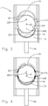
- FIG. 1 refers to a pipe cutting tool, in which a fixed knife 12 and a translatable knife 14 are arranged in a frame. Both knives 12, 14 are planar, and have a concave, semi-circular knife edges 121, 141, respectively; adapted to the dimensions of a pipe 2 (see, Figures 4-7 ) to be cut.
- the diameter of curvature of the knives edges 121, 141 are maximally equal to an inner diameter of the pipe 2.
- Each knife edge 121, 141 is limited by lateral edges 123, 143, respectively; which are here arranged in a substantial radial direction relative the semi-circular knives edges 121, 141.
- the lateral edges 123, 143 are symmetrical about an axial plane through the centers of curvature of the knives edges, to counteract the lateral forces applied to the knives 12, 14 caused by the intrusion into the pipe by the lateral edges 123, 143.
- the fixed knife 12 is fixed to the frame 11 in a first plane.
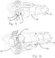
- the translatable knife 14 is arranged to be slidably moved in a second plane between a retracted initial position and a position slidably moved outward. Because the first and second planes are parallel and arranged in a distance to each other, the translatable knife 14 can overlap the fixed knife 12 when in a position slidably moved outward, such as shown in Figure 10 .
- the frame 11 is equipped with knife guiding paths 113 which are aligned to guide the translatable knife 14 during its shifting.
- a linear actuator system 16 is connected to the translatable knife 14 and the frame 11, and is arranged to slidably move the translatable knife 14.
- the linear actuator system 16 can be formed from one or more hydraulic cylinders connected to a hydraulic power unit with corresponding control valve (not shown).
- the fixed knife 12 and the translatable knife 14 are equipped their own pipe abutment 13, 15, respectively.
- the pipe abutments 13, 15 have concave abutment faces 131, 151, respectively; with diameter corresponding to the external diameter of the pipe 2.
- the centers of curvature of the abutment faces 131, 151 are coinciding with the centers of curvature 122, 142, respectively, of the respective knives edges 121, 141.
- the frame 11 comprises a first and a second frame section 11a, 11b, which are connected by a hinge arrangement 111 and a frame lock 112.
- the frame lock 112 can be pivotally attached in one of the first and second frame section 11a, 11b, and is aligned to engage lockingly with a section of the second of the first and second frame section 11a, 11b; see especially Figures 7 and 8 .
- the frame 11 can be opened such as shown in Figure 7 . This simplifies connecting the pipe cutting tool 1 and the pipe 2 to be cut.
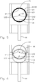
- FIG. 2 wherein it is shown an example of an arrangement 19 for resilient suspension of the pipe cutting tool 1, as the pipe cutting tool 1 is suspended in strut 193 from a carriage 192 which can be slidably moved along a roller path 191.
- the struts 193 allow the pipe cutting tool 1 to move relative the carriage 192, for example in that the struts 193are telescopic and connected with the carriage and with the pipe cutting tool via pivot joint 194.
- the struts 193 may be formed from chains.
- the purpose of the suspension arrangement 19 is to allow the pipe cutting tool 1 to position itself relative the pipe 2 without inflicting substantial strain to the suspension arrangement or pipe cutting tool 1 due to directional deviations and/or lacking centering of the pipe cutting tool 1 relative the pipe 2.
- FIGS 7-10 show a practical embodiment of the pipe cutting tool 1; here shown without suspension arrangement 19.
- the pipe cutting tool 1 is equipped with a movable secondary abutment 17 (see, Figures 7 and 9 ).
- the secondary abutment 17 is coupled to a secondary abutment actuator 18, typically in the form of a hydraulic cylinder connected to a hydraulic power unit with a corresponding control valve (not shown).
- a secondary abutment actuator 18 typically in the form of a hydraulic cylinder connected to a hydraulic power unit with a corresponding control valve (not shown).
- the pipe cutting tool 1 can be fixed onto the pipe 2 before the translatable knife 14 is slidably moved against the pipe 2.
Landscapes
- Engineering & Computer Science (AREA)
- Life Sciences & Earth Sciences (AREA)
- Mechanical Engineering (AREA)
- Mining & Mineral Resources (AREA)
- Geology (AREA)
- Forests & Forestry (AREA)
- Fluid Mechanics (AREA)
- Physics & Mathematics (AREA)
- General Life Sciences & Earth Sciences (AREA)
- Geochemistry & Mineralogy (AREA)
- Environmental & Geological Engineering (AREA)
- Knives (AREA)
- Nonmetal Cutting Devices (AREA)
- Earth Drilling (AREA)
Priority Applications (1)
| Application Number | Priority Date | Filing Date | Title |
|---|---|---|---|
| PL18742705T PL3638871T3 (pl) | 2017-06-16 | 2018-06-13 | Narzędzie do cięcia rury przewodu wiertniczego |
Applications Claiming Priority (2)
| Application Number | Priority Date | Filing Date | Title |
|---|---|---|---|
| NO20170993A NO343501B1 (no) | 2017-06-16 | 2017-06-16 | Verktøy for kutting av brønnrør |
| PCT/EP2018/065595 WO2018229097A1 (en) | 2017-06-16 | 2018-06-13 | Tool for cutting well tubular |
Publications (2)
| Publication Number | Publication Date |
|---|---|
| EP3638871A1 EP3638871A1 (en) | 2020-04-22 |
| EP3638871B1 true EP3638871B1 (en) | 2021-03-31 |
Family
ID=62952031
Family Applications (1)
| Application Number | Title | Priority Date | Filing Date |
|---|---|---|---|
| EP18742705.9A Active EP3638871B1 (en) | 2017-06-16 | 2018-06-13 | Tool for cutting well tubular |
Country Status (8)
| Country | Link |
|---|---|
| US (1) | US20200164538A1 (pl) |
| EP (1) | EP3638871B1 (pl) |
| CN (1) | CN110799723B (pl) |
| DK (1) | DK3638871T3 (pl) |
| MX (1) | MX2019013959A (pl) |
| NO (1) | NO343501B1 (pl) |
| PL (1) | PL3638871T3 (pl) |
| WO (1) | WO2018229097A1 (pl) |
Families Citing this family (3)
| Publication number | Priority date | Publication date | Assignee | Title |
|---|---|---|---|---|
| NO344001B1 (en) * | 2017-11-29 | 2019-08-12 | Smart Installations As | Method for cutting a tubular structure at a drill floor and a cutting tool for carrying out such method |
| CN113118541A (zh) * | 2021-04-13 | 2021-07-16 | 江苏华阳管业股份有限公司 | 一种弯头生产线及弯头的制造方法 |
| CN113733738B (zh) * | 2021-09-06 | 2022-12-09 | 廊坊市文豪印刷包装有限公司 | 一种高效的包装印刷机 |
Family Cites Families (18)
| Publication number | Priority date | Publication date | Assignee | Title |
|---|---|---|---|---|
| US3561526A (en) * | 1969-09-03 | 1971-02-09 | Cameron Iron Works Inc | Pipe shearing ram assembly for blowout preventer |
| CH568117A5 (pl) * | 1974-03-07 | 1975-10-31 | Fischer Ag Georg | |
| US4458421A (en) | 1982-06-01 | 1984-07-10 | Lew Hyok S | Counter-reciprocating double blade saw |
| IT1253716B (it) | 1991-11-06 | 1995-08-23 | Metodo e dispositivo per il taglio di strutture subacquee. | |
| NO320571B1 (no) | 2000-11-02 | 2005-12-27 | Norse Cutting As | Anordning ved sagblad |
| NO20022668A (no) | 2002-06-06 | 2003-05-12 | Norse Cutting & Abandonment As | Anordning ved et hydraulisk kutteverktøy |
| US7243646B2 (en) * | 2004-03-05 | 2007-07-17 | Todack James J | Apparatus and method for shearing reinforced concrete piles and metal piles and crushing reinforced concrete piles |
| US7351010B1 (en) * | 2005-06-17 | 2008-04-01 | Kelly John M | Method and apparatus for salvaging underwater pipelines |
| US7367396B2 (en) * | 2006-04-25 | 2008-05-06 | Varco I/P, Inc. | Blowout preventers and methods of use |
| US20120291606A1 (en) * | 2007-05-16 | 2012-11-22 | Khoury John J | Tubular cutting apparatus |
| JP5167493B2 (ja) * | 2008-05-12 | 2013-03-21 | 株式会社デュプロ | 断裁装置 |
| GB201001161D0 (en) * | 2010-01-25 | 2010-03-10 | Bamford Antony S | Underwater tubing workover |
| NO336345B1 (no) * | 2011-11-15 | 2015-08-03 | Altus Intervention As | Anordning for kutting av en kabel i et borehull i grunnen |
| US8656939B2 (en) * | 2012-02-29 | 2014-02-25 | Chevron U.S.A. Inc. | Apparatus, system and methods for sealing and severing a subsea pipeline |
| CN104908100B (zh) * | 2014-04-13 | 2016-12-07 | 嵊州市宜留机械科技有限公司 | 用于茯苓快速切片的机械设备 |
| CN105298422B (zh) * | 2015-10-21 | 2019-05-07 | 中国石油天然气集团公司 | 连续管水力旋转切割系统 |
| CN205503073U (zh) * | 2016-02-17 | 2016-08-24 | 辽河石油勘探局 | 一种水平井可退可捞式内切割装置 |
| EP3333994B1 (en) * | 2016-12-09 | 2020-03-18 | CEMBRE S.p.A. | Working head for a compression or cutting tool |
-
2017
- 2017-06-16 NO NO20170993A patent/NO343501B1/no unknown
-
2018
- 2018-06-13 WO PCT/EP2018/065595 patent/WO2018229097A1/en not_active Ceased
- 2018-06-13 US US16/615,412 patent/US20200164538A1/en not_active Abandoned
- 2018-06-13 PL PL18742705T patent/PL3638871T3/pl unknown
- 2018-06-13 CN CN201880039676.8A patent/CN110799723B/zh active Active
- 2018-06-13 EP EP18742705.9A patent/EP3638871B1/en active Active
- 2018-06-13 DK DK18742705.9T patent/DK3638871T3/da active
- 2018-06-13 MX MX2019013959A patent/MX2019013959A/es unknown
Also Published As
| Publication number | Publication date |
|---|---|
| PL3638871T3 (pl) | 2021-07-12 |
| NO20170993A1 (no) | 2018-12-17 |
| CN110799723A (zh) | 2020-02-14 |
| WO2018229097A1 (en) | 2018-12-20 |
| MX2019013959A (es) | 2020-07-14 |
| US20200164538A1 (en) | 2020-05-28 |
| NO343501B1 (no) | 2019-03-25 |
| DK3638871T3 (da) | 2021-04-26 |
| CN110799723B (zh) | 2021-12-14 |
| EP3638871A1 (en) | 2020-04-22 |
Similar Documents
| Publication | Publication Date | Title |
|---|---|---|
| EP3638871B1 (en) | Tool for cutting well tubular | |
| US4330143A (en) | Apparatus for connecting together flowline end portions | |
| US12366318B2 (en) | Winch boom and method for trenchless replacement | |
| US10450834B2 (en) | Ball valve | |
| US10415608B2 (en) | Hydraulic cylinder cover | |
| US11892115B2 (en) | Valve insertion tool | |
| EP0087971B1 (en) | Apparatus for removing covering material from underwater pipelines | |
| EP3431233B1 (en) | Subsea cutting assembly | |
| GB2540780A (en) | Restricting the bending of an underwater cable | |
| EP3172471B1 (en) | Multiple failure mode clamps and related methods | |
| US9175536B2 (en) | Pipe end plug apparatus and method | |
| EP2597345B1 (en) | Flange assembly | |
| WO2008147312A1 (en) | Cutting device | |
| EP3621762B1 (en) | Rotary cutting device | |
| EP2591271B1 (en) | Sealing device for connecting two pipes | |
| GB2589260A (en) | Pipe structure and construction method | |
| US20160319979A1 (en) | Gut Hook Bladed Pipe Slitter | |
| GB2570034A (en) | Improved cutting tool | |
| EP2896468A2 (en) | Protection device | |
| US10144072B2 (en) | Plastic tube fitting removal tool | |
| WO2000066924A1 (en) | Pipe sealing system | |
| AU2018101802A4 (en) | Hydraulic ram safety support | |
| FR3012010A1 (fr) | Appareil d'exploitation de produits ligneux | |
| EP4544214A1 (en) | Gate insert valve and method of insertion into pressurized pipelines | |
| WO2006133706A1 (en) | A holding device for holding pull rods in a pulling tool as well as use thereof |
Legal Events
| Date | Code | Title | Description |
|---|---|---|---|
| STAA | Information on the status of an ep patent application or granted ep patent |
Free format text: STATUS: UNKNOWN |
|
| STAA | Information on the status of an ep patent application or granted ep patent |
Free format text: STATUS: THE INTERNATIONAL PUBLICATION HAS BEEN MADE |
|
| PUAI | Public reference made under article 153(3) epc to a published international application that has entered the european phase |
Free format text: ORIGINAL CODE: 0009012 |
|
| STAA | Information on the status of an ep patent application or granted ep patent |
Free format text: STATUS: REQUEST FOR EXAMINATION WAS MADE |
|
| 17P | Request for examination filed |
Effective date: 20191216 |
|
| AK | Designated contracting states |
Kind code of ref document: A1 Designated state(s): AL AT BE BG CH CY CZ DE DK EE ES FI FR GB GR HR HU IE IS IT LI LT LU LV MC MK MT NL NO PL PT RO RS SE SI SK SM TR |
|
| AX | Request for extension of the european patent |
Extension state: BA ME |
|
| DAV | Request for validation of the european patent (deleted) | ||
| DAX | Request for extension of the european patent (deleted) | ||
| GRAP | Despatch of communication of intention to grant a patent |
Free format text: ORIGINAL CODE: EPIDOSNIGR1 |
|
| STAA | Information on the status of an ep patent application or granted ep patent |
Free format text: STATUS: GRANT OF PATENT IS INTENDED |
|
| RIC1 | Information provided on ipc code assigned before grant |
Ipc: B23D 21/00 20060101ALI20201214BHEP Ipc: F16L 55/105 20060101ALI20201214BHEP Ipc: B23D 29/00 20060101ALI20201214BHEP Ipc: B26D 1/00 20060101ALI20201214BHEP Ipc: B26D 1/08 20060101ALI20201214BHEP Ipc: E21B 29/00 20060101AFI20201214BHEP Ipc: B26D 3/16 20060101ALI20201214BHEP |
|
| INTG | Intention to grant announced |
Effective date: 20210114 |
|
| RIN1 | Information on inventor provided before grant (corrected) |
Inventor name: HETLAND, SOELVE |
|
| GRAS | Grant fee paid |
Free format text: ORIGINAL CODE: EPIDOSNIGR3 |
|
| GRAA | (expected) grant |
Free format text: ORIGINAL CODE: 0009210 |
|
| STAA | Information on the status of an ep patent application or granted ep patent |
Free format text: STATUS: THE PATENT HAS BEEN GRANTED |
|
| AK | Designated contracting states |
Kind code of ref document: B1 Designated state(s): AL AT BE BG CH CY CZ DE DK EE ES FI FR GB GR HR HU IE IS IT LI LT LU LV MC MK MT NL NO PL PT RO RS SE SI SK SM TR |
|
| REG | Reference to a national code |
Ref country code: GB Ref legal event code: FG4D Ref country code: CH Ref legal event code: EP |
|
| REG | Reference to a national code |
Ref country code: DE Ref legal event code: R096 Ref document number: 602018014847 Country of ref document: DE Ref country code: AT Ref legal event code: REF Ref document number: 1377108 Country of ref document: AT Kind code of ref document: T Effective date: 20210415 |
|
| REG | Reference to a national code |
Ref country code: RO Ref legal event code: EPE |
|
| REG | Reference to a national code |
Ref country code: DK Ref legal event code: T3 Effective date: 20210422 |
|
| REG | Reference to a national code |
Ref country code: NL Ref legal event code: FP Ref country code: IE Ref legal event code: FG4D |
|
| REG | Reference to a national code |
Ref country code: LT Ref legal event code: MG9D |
|
| PG25 | Lapsed in a contracting state [announced via postgrant information from national office to epo] |
Ref country code: BG Free format text: LAPSE BECAUSE OF FAILURE TO SUBMIT A TRANSLATION OF THE DESCRIPTION OR TO PAY THE FEE WITHIN THE PRESCRIBED TIME-LIMIT Effective date: 20210630 Ref country code: HR Free format text: LAPSE BECAUSE OF FAILURE TO SUBMIT A TRANSLATION OF THE DESCRIPTION OR TO PAY THE FEE WITHIN THE PRESCRIBED TIME-LIMIT Effective date: 20210331 Ref country code: FI Free format text: LAPSE BECAUSE OF FAILURE TO SUBMIT A TRANSLATION OF THE DESCRIPTION OR TO PAY THE FEE WITHIN THE PRESCRIBED TIME-LIMIT Effective date: 20210331 |
|
| REG | Reference to a national code |
Ref country code: NO Ref legal event code: T2 Effective date: 20210331 |
|
| PG25 | Lapsed in a contracting state [announced via postgrant information from national office to epo] |
Ref country code: LV Free format text: LAPSE BECAUSE OF FAILURE TO SUBMIT A TRANSLATION OF THE DESCRIPTION OR TO PAY THE FEE WITHIN THE PRESCRIBED TIME-LIMIT Effective date: 20210331 Ref country code: RS Free format text: LAPSE BECAUSE OF FAILURE TO SUBMIT A TRANSLATION OF THE DESCRIPTION OR TO PAY THE FEE WITHIN THE PRESCRIBED TIME-LIMIT Effective date: 20210331 Ref country code: SE Free format text: LAPSE BECAUSE OF FAILURE TO SUBMIT A TRANSLATION OF THE DESCRIPTION OR TO PAY THE FEE WITHIN THE PRESCRIBED TIME-LIMIT Effective date: 20210331 |
|
| PGFP | Annual fee paid to national office [announced via postgrant information from national office to epo] |
Ref country code: PL Payment date: 20210519 Year of fee payment: 4 |
|
| REG | Reference to a national code |
Ref country code: AT Ref legal event code: MK05 Ref document number: 1377108 Country of ref document: AT Kind code of ref document: T Effective date: 20210331 |
|
| PG25 | Lapsed in a contracting state [announced via postgrant information from national office to epo] |
Ref country code: CZ Free format text: LAPSE BECAUSE OF FAILURE TO SUBMIT A TRANSLATION OF THE DESCRIPTION OR TO PAY THE FEE WITHIN THE PRESCRIBED TIME-LIMIT Effective date: 20210331 Ref country code: EE Free format text: LAPSE BECAUSE OF FAILURE TO SUBMIT A TRANSLATION OF THE DESCRIPTION OR TO PAY THE FEE WITHIN THE PRESCRIBED TIME-LIMIT Effective date: 20210331 Ref country code: LT Free format text: LAPSE BECAUSE OF FAILURE TO SUBMIT A TRANSLATION OF THE DESCRIPTION OR TO PAY THE FEE WITHIN THE PRESCRIBED TIME-LIMIT Effective date: 20210331 Ref country code: AT Free format text: LAPSE BECAUSE OF FAILURE TO SUBMIT A TRANSLATION OF THE DESCRIPTION OR TO PAY THE FEE WITHIN THE PRESCRIBED TIME-LIMIT Effective date: 20210331 Ref country code: SM Free format text: LAPSE BECAUSE OF FAILURE TO SUBMIT A TRANSLATION OF THE DESCRIPTION OR TO PAY THE FEE WITHIN THE PRESCRIBED TIME-LIMIT Effective date: 20210331 |
|
| PG25 | Lapsed in a contracting state [announced via postgrant information from national office to epo] |
Ref country code: PT Free format text: LAPSE BECAUSE OF FAILURE TO SUBMIT A TRANSLATION OF THE DESCRIPTION OR TO PAY THE FEE WITHIN THE PRESCRIBED TIME-LIMIT Effective date: 20210802 Ref country code: SK Free format text: LAPSE BECAUSE OF FAILURE TO SUBMIT A TRANSLATION OF THE DESCRIPTION OR TO PAY THE FEE WITHIN THE PRESCRIBED TIME-LIMIT Effective date: 20210331 Ref country code: IS Free format text: LAPSE BECAUSE OF FAILURE TO SUBMIT A TRANSLATION OF THE DESCRIPTION OR TO PAY THE FEE WITHIN THE PRESCRIBED TIME-LIMIT Effective date: 20210731 |
|
| REG | Reference to a national code |
Ref country code: DE Ref legal event code: R119 Ref document number: 602018014847 Country of ref document: DE |
|
| PG25 | Lapsed in a contracting state [announced via postgrant information from national office to epo] |
Ref country code: ES Free format text: LAPSE BECAUSE OF FAILURE TO SUBMIT A TRANSLATION OF THE DESCRIPTION OR TO PAY THE FEE WITHIN THE PRESCRIBED TIME-LIMIT Effective date: 20210331 Ref country code: MC Free format text: LAPSE BECAUSE OF FAILURE TO SUBMIT A TRANSLATION OF THE DESCRIPTION OR TO PAY THE FEE WITHIN THE PRESCRIBED TIME-LIMIT Effective date: 20210331 Ref country code: AL Free format text: LAPSE BECAUSE OF FAILURE TO SUBMIT A TRANSLATION OF THE DESCRIPTION OR TO PAY THE FEE WITHIN THE PRESCRIBED TIME-LIMIT Effective date: 20210331 |
|
| REG | Reference to a national code |
Ref country code: CH Ref legal event code: PL |
|
| PLBE | No opposition filed within time limit |
Free format text: ORIGINAL CODE: 0009261 |
|
| STAA | Information on the status of an ep patent application or granted ep patent |
Free format text: STATUS: NO OPPOSITION FILED WITHIN TIME LIMIT |
|
| 26N | No opposition filed |
Effective date: 20220104 |
|
| REG | Reference to a national code |
Ref country code: BE Ref legal event code: MM Effective date: 20210630 |
|
| PG25 | Lapsed in a contracting state [announced via postgrant information from national office to epo] |
Ref country code: LU Free format text: LAPSE BECAUSE OF NON-PAYMENT OF DUE FEES Effective date: 20210613 |
|
| PG25 | Lapsed in a contracting state [announced via postgrant information from national office to epo] |
Ref country code: LI Free format text: LAPSE BECAUSE OF NON-PAYMENT OF DUE FEES Effective date: 20210630 Ref country code: IE Free format text: LAPSE BECAUSE OF NON-PAYMENT OF DUE FEES Effective date: 20210613 Ref country code: DE Free format text: LAPSE BECAUSE OF NON-PAYMENT OF DUE FEES Effective date: 20220101 Ref country code: CH Free format text: LAPSE BECAUSE OF NON-PAYMENT OF DUE FEES Effective date: 20210630 |
|
| PG25 | Lapsed in a contracting state [announced via postgrant information from national office to epo] |
Ref country code: IS Free format text: LAPSE BECAUSE OF FAILURE TO SUBMIT A TRANSLATION OF THE DESCRIPTION OR TO PAY THE FEE WITHIN THE PRESCRIBED TIME-LIMIT Effective date: 20210731 Ref country code: FR Free format text: LAPSE BECAUSE OF NON-PAYMENT OF DUE FEES Effective date: 20210630 |
|
| PG25 | Lapsed in a contracting state [announced via postgrant information from national office to epo] |
Ref country code: BE Free format text: LAPSE BECAUSE OF NON-PAYMENT OF DUE FEES Effective date: 20210630 |
|
| PG25 | Lapsed in a contracting state [announced via postgrant information from national office to epo] |
Ref country code: CY Free format text: LAPSE BECAUSE OF FAILURE TO SUBMIT A TRANSLATION OF THE DESCRIPTION OR TO PAY THE FEE WITHIN THE PRESCRIBED TIME-LIMIT Effective date: 20210331 |
|
| PG25 | Lapsed in a contracting state [announced via postgrant information from national office to epo] |
Ref country code: HU Free format text: LAPSE BECAUSE OF FAILURE TO SUBMIT A TRANSLATION OF THE DESCRIPTION OR TO PAY THE FEE WITHIN THE PRESCRIBED TIME-LIMIT; INVALID AB INITIO Effective date: 20180613 Ref country code: GR Free format text: LAPSE BECAUSE OF FAILURE TO SUBMIT A TRANSLATION OF THE DESCRIPTION OR TO PAY THE FEE WITHIN THE PRESCRIBED TIME-LIMIT Effective date: 20210331 |
|
| PG25 | Lapsed in a contracting state [announced via postgrant information from national office to epo] |
Ref country code: MK Free format text: LAPSE BECAUSE OF FAILURE TO SUBMIT A TRANSLATION OF THE DESCRIPTION OR TO PAY THE FEE WITHIN THE PRESCRIBED TIME-LIMIT Effective date: 20210331 |
|
| PG25 | Lapsed in a contracting state [announced via postgrant information from national office to epo] |
Ref country code: MT Free format text: LAPSE BECAUSE OF FAILURE TO SUBMIT A TRANSLATION OF THE DESCRIPTION OR TO PAY THE FEE WITHIN THE PRESCRIBED TIME-LIMIT Effective date: 20210331 |
|
| PG25 | Lapsed in a contracting state [announced via postgrant information from national office to epo] |
Ref country code: PL Free format text: LAPSE BECAUSE OF NON-PAYMENT OF DUE FEES Effective date: 20220613 |
|
| PG25 | Lapsed in a contracting state [announced via postgrant information from national office to epo] |
Ref country code: PL Free format text: LAPSE BECAUSE OF NON-PAYMENT OF DUE FEES Effective date: 20220613 |
|
| PGFP | Annual fee paid to national office [announced via postgrant information from national office to epo] |
Ref country code: NL Payment date: 20250527 Year of fee payment: 8 |
|
| PGFP | Annual fee paid to national office [announced via postgrant information from national office to epo] |
Ref country code: GB Payment date: 20250520 Year of fee payment: 8 Ref country code: DK Payment date: 20250527 Year of fee payment: 8 |
|
| PGFP | Annual fee paid to national office [announced via postgrant information from national office to epo] |
Ref country code: NO Payment date: 20250520 Year of fee payment: 8 |
|
| PGFP | Annual fee paid to national office [announced via postgrant information from national office to epo] |
Ref country code: IT Payment date: 20250521 Year of fee payment: 8 |
|
| PGFP | Annual fee paid to national office [announced via postgrant information from national office to epo] |
Ref country code: RO Payment date: 20250528 Year of fee payment: 8 |
|
| PG25 | Lapsed in a contracting state [announced via postgrant information from national office to epo] |
Ref country code: TR Free format text: LAPSE BECAUSE OF FAILURE TO SUBMIT A TRANSLATION OF THE DESCRIPTION OR TO PAY THE FEE WITHIN THE PRESCRIBED TIME-LIMIT Effective date: 20210331 |