EP3638609B1 - Verfahren und system zur erkennung des rückwärtigen zustands - Google Patents
Verfahren und system zur erkennung des rückwärtigen zustands Download PDFInfo
- Publication number
- EP3638609B1 EP3638609B1 EP18818440.2A EP18818440A EP3638609B1 EP 3638609 B1 EP3638609 B1 EP 3638609B1 EP 18818440 A EP18818440 A EP 18818440A EP 3638609 B1 EP3638609 B1 EP 3638609B1
- Authority
- EP
- European Patent Office
- Prior art keywords
- vehicle
- sensor apparatus
- trailer
- block
- bay
- Prior art date
- Legal status (The legal status is an assumption and is not a legal conclusion. Google has not performed a legal analysis and makes no representation as to the accuracy of the status listed.)
- Active
Links
Images


Classifications
-
- G—PHYSICS
- G01—MEASURING; TESTING
- G01S—RADIO DIRECTION-FINDING; RADIO NAVIGATION; DETERMINING DISTANCE OR VELOCITY BY USE OF RADIO WAVES; LOCATING OR PRESENCE-DETECTING BY USE OF THE REFLECTION OR RERADIATION OF RADIO WAVES; ANALOGOUS ARRANGEMENTS USING OTHER WAVES
- G01S5/00—Position-fixing by co-ordinating two or more direction or position line determinations; Position-fixing by co-ordinating two or more distance determinations
- G01S5/0009—Transmission of position information to remote stations
- G01S5/0018—Transmission from mobile station to base station
- G01S5/0036—Transmission from mobile station to base station of measured values, i.e. measurement on mobile and position calculation on base station
-
- B—PERFORMING OPERATIONS; TRANSPORTING
- B60—VEHICLES IN GENERAL
- B60Q—ARRANGEMENT OF SIGNALLING OR LIGHTING DEVICES, THE MOUNTING OR SUPPORTING THEREOF OR CIRCUITS THEREFOR, FOR VEHICLES IN GENERAL
- B60Q9/00—Arrangement or adaptation of signal devices not provided for in one of main groups B60Q1/00 - B60Q7/00, e.g. haptic signalling
- B60Q9/002—Arrangement or adaptation of signal devices not provided for in one of main groups B60Q1/00 - B60Q7/00, e.g. haptic signalling for parking purposes, e.g. for warning the driver that his vehicle has contacted or is about to contact an obstacle
-
- G—PHYSICS
- G01—MEASURING; TESTING
- G01S—RADIO DIRECTION-FINDING; RADIO NAVIGATION; DETERMINING DISTANCE OR VELOCITY BY USE OF RADIO WAVES; LOCATING OR PRESENCE-DETECTING BY USE OF THE REFLECTION OR RERADIATION OF RADIO WAVES; ANALOGOUS ARRANGEMENTS USING OTHER WAVES
- G01S19/00—Satellite radio beacon positioning systems; Determining position, velocity or attitude using signals transmitted by such systems
- G01S19/38—Determining a navigation solution using signals transmitted by a satellite radio beacon positioning system
- G01S19/39—Determining a navigation solution using signals transmitted by a satellite radio beacon positioning system the satellite radio beacon positioning system transmitting time-stamped messages, e.g. GPS [Global Positioning System], GLONASS [Global Orbiting Navigation Satellite System] or GALILEO
- G01S19/42—Determining position
-
- G—PHYSICS
- G01—MEASURING; TESTING
- G01S—RADIO DIRECTION-FINDING; RADIO NAVIGATION; DETERMINING DISTANCE OR VELOCITY BY USE OF RADIO WAVES; LOCATING OR PRESENCE-DETECTING BY USE OF THE REFLECTION OR RERADIATION OF RADIO WAVES; ANALOGOUS ARRANGEMENTS USING OTHER WAVES
- G01S5/00—Position-fixing by co-ordinating two or more direction or position line determinations; Position-fixing by co-ordinating two or more distance determinations
- G01S5/02—Position-fixing by co-ordinating two or more direction or position line determinations; Position-fixing by co-ordinating two or more distance determinations using radio waves
- G01S5/0295—Proximity-based methods, e.g. position inferred from reception of particular signals
-
- G—PHYSICS
- G05—CONTROLLING; REGULATING
- G05D—SYSTEMS FOR CONTROLLING OR REGULATING NON-ELECTRIC VARIABLES
- G05D1/00—Control of position, course, altitude or attitude of land, water, air or space vehicles, e.g. using automatic pilots
- G05D1/02—Control of position or course in two dimensions
- G05D1/021—Control of position or course in two dimensions specially adapted to land vehicles
- G05D1/0231—Control of position or course in two dimensions specially adapted to land vehicles using optical position detecting means
- G05D1/0246—Control of position or course in two dimensions specially adapted to land vehicles using optical position detecting means using a video camera in combination with image processing means
-
- G—PHYSICS
- G06—COMPUTING OR CALCULATING; COUNTING
- G06V—IMAGE OR VIDEO RECOGNITION OR UNDERSTANDING
- G06V20/00—Scenes; Scene-specific elements
- G06V20/50—Context or environment of the image
- G06V20/56—Context or environment of the image exterior to a vehicle by using sensors mounted on the vehicle
-
- G—PHYSICS
- G07—CHECKING-DEVICES
- G07C—TIME OR ATTENDANCE REGISTERS; REGISTERING OR INDICATING THE WORKING OF MACHINES; GENERATING RANDOM NUMBERS; VOTING OR LOTTERY APPARATUS; ARRANGEMENTS, SYSTEMS OR APPARATUS FOR CHECKING NOT PROVIDED FOR ELSEWHERE
- G07C5/00—Registering or indicating the working of vehicles
- G07C5/008—Registering or indicating the working of vehicles communicating information to a remotely located station
-
- G—PHYSICS
- G01—MEASURING; TESTING
- G01S—RADIO DIRECTION-FINDING; RADIO NAVIGATION; DETERMINING DISTANCE OR VELOCITY BY USE OF RADIO WAVES; LOCATING OR PRESENCE-DETECTING BY USE OF THE REFLECTION OR RERADIATION OF RADIO WAVES; ANALOGOUS ARRANGEMENTS USING OTHER WAVES
- G01S2205/00—Position-fixing by co-ordinating two or more direction or position line determinations; Position-fixing by co-ordinating two or more distance determinations
- G01S2205/01—Position-fixing by co-ordinating two or more direction or position line determinations; Position-fixing by co-ordinating two or more distance determinations specially adapted for specific applications
-
- G—PHYSICS
- G06—COMPUTING OR CALCULATING; COUNTING
- G06V—IMAGE OR VIDEO RECOGNITION OR UNDERSTANDING
- G06V10/00—Arrangements for image or video recognition or understanding
- G06V10/20—Image preprocessing
- G06V10/24—Aligning, centring, orientation detection or correction of the image
- G06V10/245—Aligning, centring, orientation detection or correction of the image by locating a pattern; Special marks for positioning
-
- G—PHYSICS
- G08—SIGNALLING
- G08G—TRAFFIC CONTROL SYSTEMS
- G08G1/00—Traffic control systems for road vehicles
-
- G—PHYSICS
- G08—SIGNALLING
- G08G—TRAFFIC CONTROL SYSTEMS
- G08G1/00—Traffic control systems for road vehicles
- G08G1/20—Monitoring the location of vehicles belonging to a group, e.g. fleet of vehicles, countable or determined number of vehicles
Definitions
- the present disclosure relates to vehicles, and in particular relates to rear status detection for vehicles.
- doors on a truck or trailer may not be secured properly and thus be only partially open. During reversing maneuvers, such unsecured doors may be damaged.
- US5938710 discloses an industrial truck, in particular a counterbalanced front forklift truck, which can be operated both manually and automatically.
- the forklift truck is equipped with a fork to handle pallets and loads located thereon.
- the forklift truck is equipped for automatic operation with a control system which can be brought into active connection with the vehicle drive system, the vehicle steering system, the vehicle braking system or the movement control system for the fork.
- the truck further includes a system for the input and storage of possible travel routes and a transport task, a system for the autonomous determination of the position of the vehicle in the room, a system for the control of the movement of the vehicle as a function of its position in the room and of the predefined transport task, a system for detection of the presence, the position, and the orientation of a pallet, a system for the control of the movement of the fork and/or of the vehicle as a function of the position, the orientation of the pallet, and the transport task, and a system for the deceleration of the vehicle in the presence of obstacles.
- a system for the input and storage of possible travel routes and a transport task a system for the autonomous determination of the position of the vehicle in the room
- a system for the control of the movement of the vehicle as a function of its position in the room and of the predefined transport task a system for detection of the presence, the position, and the orientation of a pallet
- a system for the control of the movement of the fork and/or of the vehicle as
- US2015228077 A1 discloses a computer-implemented method for mapping, localization and pose correction which includes determining a current position of a vehicle along a travel route and a set of currently observable landmarks along the travel route relative to the current position.
- Espinace P, et al. "Unsupervised identification of useful visual landmarks using multiple segmentations and top-down feedback", Robotics and Autonomous Systems, volume 56, no. 6, pages 538-548 (2008 ) discloses an unsupervised method for automatic selection and subsequent recognition of suitable visual landmarks using images acquired by a mobile robot.
- the present disclosure provides a method for identifying a loading bay at a facility to which a vehicle is reversing.
- the present disclosure further provides a system comprising a sensor apparatus connected with a vehicle and a server.
- the present disclosure further provides a computer program.
- sensor systems may be included on the vehicle and include a plurality of sensor apparatuses operating remotely from a central monitoring station to provide remote sensor data to a management or monitoring hub.
- a sensor system involves fleet management or cargo management systems.
- sensors may be placed on a trailer, shipping container or similar product to provide a central station with information regarding the container.
- information may include, but is not limited to, information concerning the current location of the trailer or shipping container, the temperature inside the shipping container or trailer, or that the doors on the shipping container or trailer are closed, whether a sudden acceleration or deceleration event has occurred, the tilt angle of the trailer or shipping container, among other data.
- the sensor apparatus may be secured to a vehicle itself.
- vehicle can include any motorized vehicle such as a truck, tractor, car, boat, motorcycle, snow machine, among others, and can further include a trailer, shipping container or other such cargo moving container, whether attached to a motorized vehicle or not.
- a sensor apparatus may be any apparatus that is capable of providing data or information from sensors associated with the sensor apparatus to a central monitoring or control station. Sensors associated with the sensor apparatus may either be physically part of the sensor apparatus, for example a built-in global positioning system (GPS) chipset, or may be associated with the sensor apparatus through short range wired or wireless communications. For example, a tire pressure monitor may provide information through a Bluetooth TM Low Energy (BLE) signal from the tire to the sensor apparatus. In other cases, a camera may be part of the sensor apparatus or may communicate with a sensor apparatus through wired or wireless technologies. Other examples of sensors are possible.
- GPS global positioning system
- BLE Bluetooth TM Low Energy
- a central monitoring station may be any server or combination of servers that are remote from the sensor apparatus.
- the central monitoring station can receive data from a plurality of sensor apparatuses, and in some cases may have software to monitor such data and provide alerts to operators if data is outside of the predetermined boundaries.
- FIG. 1 One sensor apparatus is shown with regard to Figure 1 .
- the sensor apparatus of Figure 1 is however merely an example and other sensor apparatuses could equally be used in accordance with the examples of the present disclosure.
- Sensor apparatus 110 can be any computing device or network node.
- Such computing device or network node may include any type of electronic device, including but not limited to, mobile devices such as smartphones or cellular telephones. Examples can further include fixed or mobile devices, such as internet of things devices, endpoints, home automation devices, medical equipment in hospital or home environments, inventory tracking devices, environmental monitoring devices, energy management devices, infrastructure management devices, vehicles or devices for vehicles, fixed electronic devices, among others.
- Sensor apparatus 110 comprises a processor 120 and at least one communications subsystem 130, where the processor 120 and communications subsystem 130 cooperate to perform the methods described herein.
- Communications subsystem 130 may comprise multiple subsystems, for example for different radio technologies.
- Communications subsystem 130 allows sensor apparatus 110 to communicate with other devices or network elements. Communications subsystem 130 may use one or more of a variety of communications types, including but not limited to cellular, satellite, Bluetooth TM , Bluetooth TM Low Energy, Wi-Fi, wireless local area network (WLAN), near field communications (NFC), ZigBee, wired connections such as Ethernet or fiber, among other options.
- communications types including but not limited to cellular, satellite, Bluetooth TM , Bluetooth TM Low Energy, Wi-Fi, wireless local area network (WLAN), near field communications (NFC), ZigBee, wired connections such as Ethernet or fiber, among other options.
- a communications subsystem 130 for wireless communications will typically have one or more receivers and transmitters, as well as associated components such as one or more antenna elements, local oscillators (LOs), and may include a processing module such as a digital signal processor (DSP).
- LOs local oscillators
- DSP digital signal processor
- Processor 120 generally controls the overall operation of the sensor apparatus 110 and is configured to execute programmable logic, which may be stored, along with data, using memory 140.
- Memory 140 can be any tangible, non-transitory computer readable storage medium, including but not limited to optical (e.g., CD, DVD, etc.), magnetic (e.g., tape), flash drive, hard drive, or other memory known in the art.
- sensor apparatus 110 may access data or programmable logic from an external storage medium, for example through communications subsystem 130.
- sensor apparatus 110 may utilize a plurality of sensors, which may either be part of sensor apparatus 110 in some examples or may communicate with sensor apparatus 110 in other examples .
- processor 120 may receive input from a sensor subsystem 150.
- sensors in the example of Figure 1 include a positioning sensor 151, a vibration sensor 152, a temperature sensor 153, one or more image sensors 154, accelerometer 155, light sensors 156, gyroscopic sensors 157, and other sensors 158.
- Other sensors may be any sensor that is capable of reading or obtaining data that may be useful for sensor apparatus 110.
- the sensors shown in the example of Figure 1 are merely examples, and in other examples different sensors or a subset of sensors shown in Figure 1 may be used.
- Communications between the various elements of sensor apparatus 110 may be through an internal bus 160. However, other forms of communication are possible.
- Sensor apparatus 110 may be affixed to any fixed or portable platform.
- sensor apparatus 110 may be affixed to shipping containers, truck trailers, truck cabs.
- sensor apparatus 110 may be affixed to any vehicle, including motor vehicles (e.g., automobiles, cars, trucks, buses, motorcycles, etc.), aircraft (e.g., airplanes, unmanned aerial vehicles, unmanned aircraft systems, drones, helicopters, etc.), spacecraft (e.g., spaceplanes, space shuttles, space capsules, space stations, satellites, etc.), watercraft (e.g., ships, boats, hovercraft, submarines, etc.), railed vehicles (e.g., trains and trams, etc.), and other types of vehicles including any combinations of any of the foregoing, whether currently existing or after arising, among others.
- motor vehicles e.g., automobiles, cars, trucks, buses, motorcycles, etc.
- aircraft e.g., airplanes, unmanned aerial vehicles, unmanned aircraft systems, drones, helicopter
- sensor apparatus 110 could be carried by a user.
- sensor apparatus 110 may be affixed to stationary objects including buildings, lamp posts, fences, cranes, among other options.
- sensor apparatus 110 may be a power limited device.
- sensor apparatus 110 could be a battery operated device that can be affixed to a shipping container or trailer in some examples.
- Other limited power sources could include any limited power supply, such as a small generator or dynamo, a fuel cell, solar power, among other options.
- sensor apparatus 110 may utilize external power, for example from the engine of a tractor pulling the trailer, from a land power source for example on a plugged in recreational vehicle or from a building power supply, among other options.
- External power may further allow for recharging of batteries to allow the sensor apparatus 110 to then operate in a power limited mode again.
- Recharging methods may also include other power sources, such as, but not limited to, solar, electromagnetic, acoustic or vibration charging.
- the sensor apparatus from Figure 1 may be used in a variety of environments.
- One example environment in which the sensor apparatus may be used is shown with regard to Figure 2 .
- sensor apparatus 210 sensor apparatus 210
- sensor apparatus 212 sensor apparatus 214
- sensor apparatus 214 sensor apparatus 214
- the communication may then proceed over a wide area network such as Internet 230 and proceed to servers 240 or 242.
- any one of sensors 210, 212 or 214 may communicate through satellite communication technology. This, for example, may be useful if the sensor apparatus is travelling to areas that are outside of cellular coverage or access point coverage.
- Communication between sensor apparatus 210 and server 240 may be one directional or bidirectional. Thus, in one example sensor apparatus 210 may provide information to server 240 but server 240 does not respond. In other cases, server 240 may issue commands to sensor apparatus 210 but data may be stored internally on sensor apparatus 210 until the sensor apparatus arrives at a particular location. In other cases, two-way communication may exist between sensor apparatus 210 and server 240.
- a server, central server, processing service, endpoint, Uniform Resource Identifier (URI), Uniform Resource Locator (URL), back-end, and/or processing system may be used interchangeably in the descriptions herein.
- the server functionality typically represents data processing/reporting that are not closely tied to the location of movable image capture apparatuses 210, 212, 214, etc.
- the server may be located essentially anywhere so long as it has network access to communicate with image capture apparatuses 210, 212, 214, etc.
- Server 240 may, for example, be a fleet management centralized monitoring station.
- server 240 may receive information from sensor apparatuses associated with various trailers or cargo containers, providing information such as the location of such cargo containers, the temperature within such cargo containers, any unusual events including sudden decelerations, temperature warnings when the temperature is either too high or too low, among other data.
- the server 240 may compile such information and store it for future reference. It may further alert an operator. For example, a sudden deceleration event may indicate that a trailer may have been in an accident and the operator may need to call emergency services and potentially dispatch another tractor to the location.
- server 240 may be a facilities management server, and direct loading and unloading of goods to vehicles in particular bays of the facility.
- server 240 Other examples of functionality for server 240 are possible.
- servers 240 and 242 may further have access to third-party information or information from other servers within the network.
- a data services provider 250 may provide information to server 240.
- a data repository or database 260 may also provide information to server 240.
- data services provider 250 may be a subscription based service used by server 240 to obtain current road and weather conditions.
- Data repository or database 260 may for example provide information such as image data associated with a particular location, aerial maps, or other such information.
- data service provider 250 or the data repository or database 260 is not limited to the above examples and the information provided could be any data useful to server 240.
- information from data service provider 250 or the data repository from database 260 can be provided to one or more of sensor apparatuses 210, 212, or 214 or processing at those sensor apparatuses.
- a sensor apparatus such as that described in Figures 1 and 2 above may be used for backing up of a trailer, shipping container or other vehicle.
- a camera associated with the sensor apparatus may be used.
- low-power communication methods including BLE, ZigBee, near field communications, among other short-range wireless communications could be utilized, as described below.
- a trailer and a truck typically have unobstructed views of the sky to obtain accurate GPS location fixes.
- a second set of location management algorithms may be engaged to improve accuracy and safety. Such algorithms may assist an operator to avoid damage to the trailer or doors by providing alerts. Further, using such algorithms, location accuracy may be improved at loading bays.
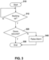
- the process of Figure 3 starts at block 310 and proceeds to block 312, in which a check is made to determine whether or not the trailer is backing up.
- the check at block 312 may comprise various techniques.
- sensors may be located on the engine of the tractor pulling the trailer. In this case, when the engine is placed into reverse, the sensors may indicate to a controller or sensor apparatus that the trailer is backing up.
- the trailer may know its orientation and utilize the GPS to determine whether or not it is backing up.
- a sensor apparatus may have a camera which indicates that objects in the rear of the trailer are getting larger and therefore that the trailer is backing up.
- the fact that the trailer has entered a geo-fenced area may indicate that the trailer is, or soon will be, backing up. Other options are possible.
- the process proceeds to loop back to block 312 until a determination is made that the trailer is backing up.
- the process proceeds to block 320 in which a check is made to determine whether the doors of the trailer are secured.
- the check at block 320 may be accomplished in various ways.
- sensors on the door may indicate if the doors are completely closed or are anchored in an open position.
- the design of a loading bay may necessitate the trailer reversing with the doors pinned to the side of the trailers in a fully open position. In other cases, the trailer should reverse with the doors fully closed.
- Various sensors may be part of the doors or latching system or anchoring system which may provide feedback to a sensor apparatus to indicate that the doors are in such a position.
- a camera on the door may indicate whether the door is fully closed or fully open. For example, if the camera shows that the image of objects behind the trailer are not completely perpendicular to the direction of motion then the doors may not be fully closed. Similarly, if the objects on the side of the trailer are not moving parallel to the direction of motion, then the doors may not be in a fully open position.
- Various imaging processing software may be used to make the determination of whether the doors are fully open are fully closed.
- a camera may be mounted to the back of the trailer but above the doors. This camera may then be used to detect the position of the doors through image recognition.
- the alarm at block 340 may be one or a combination of an audio, visual or sensory alarm within a cab of a tractor to alert the operator that the doors are not closed.
- the alarm may be a signal to a central controller, which may then provide an alert, for example to the loading bay to which the trailer is being backed up, to allow visual or auditory indicators to be provided to the driver or loading bay staff.
- a test or data notification to an in-cab solution or mobile phone may be made. Other options for alerts would be apparent to those skilled in the art having regard to the present disclosure.
- a processor may take positive action to stop potential damage of the doors. This may include, for example, actuating or overriding braking functions on a vehicle to stop the motion of the vehicle and/or trailer. If the doors can be opened or closed electronically, the functionality may further include closing the doors or opening them fully.
- a sensor apparatus on a vehicle may contain a camera or other sensors, including a gyroscope, time-of-flight (TOF), radar, light detection and ranging (LIDAR), among other options.
- This sensor apparatus may be used to determine if the door is open. If the door is open a series of potential alerts can be sent to the driver or loading bay operator to stop backing up in order to reduce potential door damage, or positive action may be taken without driver input.
- Knowledge of the exact bay that a trailer is being reversed into may be desirable at a central station. Such knowledge may allow management of the loading or unloading of the trailer, provide end to end goods tracking at a more refined level, provide which bay the goods were loaded at and which bay the goods were unloaded at, provide for terminal management functionality, among other benefits.
- GPS Global System for Mobile Communications
- loading bay doors are often located very close to each other and the level of granularity of the GPS system may not be sufficient to allow the exact determination of the loading bay that the truck or trailer is backing into.
- GPS may only be accurate to 3 meters, 10 meters or even 100 meters depending on the quality of the position fix.
- loading bays are located under an overhang or other obstruction. In this case, the sky is obscured and a GPS fix may be impossible to obtain.
- a visual sensor on the rear of the trailer may be used to take photos or images of the loading bay that is being approached.
- bay doors may, be labelled with a letter, number or code that is highly visible.
- Optical recognition of the image may then be used to determine which loading bay is being approached.
- the accurate location may be used with imperfect GPS location information to determine the exact bay that it is being backed into.
- FIG. 4 shows a perspective view of a facility having three loading bays.
- Such loading bays are labeled as loading bays 410, 412, and 414 in the example of Figure 4 .
- a letter is placed on a canopy above each door, shown as letters A, B and C.
- the use of letters on a canopy however is only one example.
- the door marking may be placed on the building, awning or on a canopy at any location, including above, at the sides or below a door. Further, the marking may be placed on the door itself.
- the marking may be a letter, number or other code that could be detected and would be visible in an image of the door.
- Figure 5 shows one process for the determination of a location at the sensor apparatus.
- the process of Figure 5 starts at block 510 and proceeds to block 512 in which a determination is made as to whether the trailer or vehicle is backing up.
- the determination of block 512 may be done similarly to the determination made at block 312 above.
- the process proceeds back to block 512 until a determination is made that the vehicles is backing up.
- a determination is made of whether the vehicle is within a threshold proximity to a bay door This may be done, for example, through visual processing indicating that there is a bay door behind the trailer and that the trailer is within a certain distance of the day door. In particular, in some cases the trailer may be backing up for other reasons, including parking in a trailer yard, among other options. In this case the determination of a bay door is not relevant.
- the vehicle may not be able to back straight into a bay.
- the backup path may involve turning the trailer during reversing.
- image capture while the bay door is not within a captured image may be irrelevant. Therefore, in the determination at block 514, if the vehicle is not within proximity to a bay door or not facing the door, then the process may proceed back to block 512 to determine whether or not the vehicle is continuing to backup.
- the process proceeds to block 520 in which an image is captured.
- the image capture may occur, for example, utilizing a camera sensor on the trailer.
- the camera sensor may be located on the tractor with a view behind the vehicle.
- the camera may be part of the sensor apparatus or may be communicating with the sensor apparatus.
- the sensor apparatus may process the image at block 530.
- the processing of the image may utilize any image processing techniques including symbol detection to detect the symbol around the bay door.
- the sensor apparatus may send the image to a server for processing, and as discussed herein, processing steps may be performed at the sensor apparatus and/or a server system.
- Supplemental information may be used to assist the image processing.
- information such as the location of the vehicle may be utilized to focus the image processing.
- the sensor apparatus through sensors on a trailer, may know at least a rough estimate of the location of the trailer. and therefore may know the facility that it is at.
- Supplemental information may further include information such as the orientation of the trailer, a tilt angle of the trailer, other images recently captured by the image capture device, among other supplemental information. The use of such information may be beneficial in image processing to narrow the possible bay doors that the trailer may be at.
- Supplemental information may further include a map overlay of information relating to the specific location and identification of bay doors on a more general purpose map. Such supplemental information may be used to allow the image processing to locate the bay markings.
- the facility may have bay markings on the left of the bay door, and the marking may be numbers. Knowledge of such information may allow for better accuracy in identifying the bay.
- Other examples of supplementary information may include a last position fix for the vehicle, stored information regarding types of markings on loading bays at the facility, stored information regarding location of markings on loading bays at the facility, physical characteristics of the facility, a bearing the loading bay is facing.
- data from the image may be compared with data stored locally or in a remote database.
- a lookup may be performed based on information within the image, such as the type of marking, the location of marking, facility color, whether the bay doors include a canopy or awning, whether the driveway is paved, among other information that may assist the image processing.
- the information about the facility may be stored at the sensor apparatus, or may be obtained from a remote store.
- Any symbol recognition software or algorithm may be utilized to facilitate the image processing at block 530.
- User input may assist such image processing.
- a bay is identified and the process proceeds to block 540.
- the identification of the bay into which the trailer is reversing is sent/signaled/transmitted to a central location.
- the signaling at block 540 is however optional. In some cases, instead of signaling, the information may be stored on the sensor apparatus for later processing. Other options are possible.
- a sensor apparatus on the vehicle starts the process at block 610 and proceeds to block 612 in which a determination is made of whether the trailer or truck or vehicle is backing up. Such determination is similar to the determinations made at blocks 312 and 512 described above.
- the process may then optionally proceed to block 614 in which a determination is made whether the trailer is within a proximity and visual range of the loading bay. This is similar to the process described above with regard to block 514 above.
- the process proceeds to block 630 in which image is transmitted to a central server.
- the image data may comprise one or more pictures or may comprise a video of the trailer backing into the loading bay.
- the image data has other supplemental information included.
- supplemental information includes location data for the last position fix of the trailer, which is utilized to narrow the potential locations that the trailer is backing into.
- Supplemental information further includes information such as the orientation of the trailer, and may further include a tilt angle of the trailer, other images recently captured by the image capture device, among other supplemental information.
- the process starts at block 710 and proceeds to block 712.
- the central server receives the image data, which includes supplemental data such as location data sent by a trailer.
- the process then proceeds to block 720 in which the image is processed.
- processing involves deriving information from the image. For example, through a database at the central monitoring station or accessible to the central monitoring station, a lookup is performed based on information within the image, such as the type of marking, the location of marking, facility color, whether the bay doors include a canopy or awning, whether the driveway is paved, among other information that may assist the image processing.
- the processing at block 720 may further use information that was sent in conjunction with the image data, such as the last position fix from the vehicle, previous image data, identity of the sensor apparatus unit, or other such information to further facilitate the processing.
- the processing at block 720 allows a bay that the trailer is backed into to be determined. This information may be stored or associated with the particular trailer for future use. It may also be used by management or coordination software for the particular facility to enable operations or optimize the facility utilization at the particular loading bay facility.
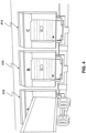
- Figure 8 shows a perspective view of an example loading bay facility having three loading bays.
- short range communications transmitters 810, 812 and 814 are placed above each loading bay door.
- sensors may be short range wireless transmitters such as Wi-Fi, Bluetooth TM , BLE, ZigBee, near field communication, among other options.
- the transmitters may be placed at other locations relative to the loading bays.
- a sensor apparatus on a trailer may look for the signals transmitted by transmitters 810, 812 and 814 and determine which signal is the strongest. Based on the strength indicator, the sensor apparatus on the trailer may know which is the closest transmitter and therefore which bay the trailer has backed into.
- Specifically transmitter 812 may be a Bluetooth TM Low Energy transmitter in which a preamble or other signal characteristic is different from the preambles or signal characteristics from transmitter 810 and 814.
- Transmitters 810, 812 and 814 may be calibrated to provide the same power level when transmitting.
- the transmitters at a location may be fingerprinted, or otherwise characterized for later processing. For example, certain transmitters may be stronger or less powerful than others. Knowing this information, the sensor apparatus may understand that each location has a particular profile and that adjustments can be applied. Moreover, the system may feed back information about a location to be analyzed and sent back to other devices that may happen upon the location.
- the profiles/fingerprints for locations may be stored at a server and sent to the sensor apparatus. If a destination for a sensor apparatus is determined, then profiles for that location may be sent to the sensor apparatus before, en route, or after arrival. Alternatively, the sensor apparatus may request a location's profile.
- a sensor on the trailer may detect signals from the three transmitters but determine that the signal from transmitter 814 is the strongest. The sensor may therefore read the preamble from the transmitter 812 and report that this signal was received with the strongest signal power level to a central controller.
- Figure 9 the process of Figure 9 starts at block 910 and proceeds to block 912 in which a determination is made that the trailer is backing up. Such determination is similar to the determination made in blocks 312, 512, and 612 above.
- the process proceeds to block 914 in which a determination is made whether the trailer detects one or more signals from a bay. Thus, if the trailer is not backing into a facility that includes wireless communications to indicate bay doors, the detection at block 914 may not exist. Therefore, if no signal is detected the process proceeds to block 920 and ends.
- the process may proceed to block 940, in which the strongest signal and information from within that signal is reported to a central monitoring station.
- the process may proceed from block 930 to block 950 in which the determination of the bay is made at the sensor apparatus and the particular bay that the trailer is backing into is then reported at block 950.
- a low-range transmitter such as transmitters 820, 830 and 840 may exist.
- Such low-range transmitters may only have a range of a few centimeters, inches, meters or feet.
- a corresponding sensor on the trailer may be located in a position that, when the trailer is close enough to transmitters 820, 830 or 840, the sensor apparatus can detect such transmitters and report that it is close to that particular bay.
- the distance the transmitter can be detected may be smaller than the width of the bay door, and thus only the transmitter on the bay door that the trailer is reversing into is detected.
- a low-power local network such as BLE, ZigBee, Wi-Fi, Bluetooth TM , near field communications, or other radiofrequency identification may be used to determine the bay at which the vehicle is now parked.
- the cost of installing such small transmitter devices used to broadcast the door name or identity and its GPS location may be low in many cases.
- the information provided based on the location could therefore substitute inaccurate GPS location information and provide for the accurate determination of which loading bay the trailer has backed into.
- Such information may be utilized by a central controller or an operations management controller for a particular facility in order to optimize operations, provide end-to-end tracking of goods, or be used with other factors which may be useful for the shipping or trailer industry.
- Such operations may not be immediate or from the server directly. They may be synchronously or asynchronously delivered, from a server or other computing system infrastructure supporting the devices/methods/systems described herein. The foregoing steps may include, in whole or in part, synchronous/asynchronous communications to/from the device/infrastructure. Moreover, communication from the electronic device may be to one or more endpoints on a network. These endpoints may be serviced by a server, a distributed computing system, a stream processor, etc. Content Delivery Networks (CDNs) may also provide may provide communication to an electronic device.
- CDNs Content Delivery Networks
- the server may also provision or indicate a data for content delivery network (CDN) to await download by the electronic device at a later time, such as a subsequent activity of electronic device.
- CDN content delivery network
- data may be sent directly from the server, or other infrastructure, such as a distributed infrastructure, or a CDN, as part of or separate from the system.
- a server, central server, service, processing service, endpoint, Uniform Resource Identifier (URI), Uniform Resource Locator (URL), back-end, and/or processing system may be used interchangeably in the descriptions and examples herein.
- Mesh networks and processing may also be used alone or in conjunction with other types as well as fog computing.
- communication may be from device to device, wherein they may use low power communication (e.g., Bluetooth, Wi-Fi), and/or a network, to communicate with other devices to get information.
- storage mediums can include any or some combination of the following: a semiconductor memory device such as a dynamic or static random access memory (a DRAM or SRAM), an erasable and programmable read-only memory (EPROM), an electrically erasable and programmable read-only memory (EEPROM) and flash memory; a magnetic disk such as a fixed, floppy and removable disk; another magnetic medium including tape; an optical medium such as a compact disk (CD) or a digital video disk (DVD); or another type of storage device.
- a semiconductor memory device such as a dynamic or static random access memory (a DRAM or SRAM), an erasable and programmable read-only memory (EPROM), an electrically erasable and programmable read-only memory (EEPROM) and flash memory
- a magnetic disk such as a fixed, floppy and removable disk
- another magnetic medium including tape an optical medium such as a compact disk (CD) or a digital video disk (DVD); or another type of storage device.
- CD compact disk
- DVD
- Such computer-readable or machine-readable storage medium or media is (are) considered to be part of an article (or article of manufacture).
- An article or article of manufacture can refer to any manufactured single component or multiple components.
- the storage medium or media can be located either in the machine running the machine-readable instructions, or located at a remote site from which machine-readable instructions can be downloaded over a network for execution.
Landscapes
- Engineering & Computer Science (AREA)
- Physics & Mathematics (AREA)
- General Physics & Mathematics (AREA)
- Radar, Positioning & Navigation (AREA)
- Remote Sensing (AREA)
- Human Computer Interaction (AREA)
- Mechanical Engineering (AREA)
- Multimedia (AREA)
- Theoretical Computer Science (AREA)
- Transportation (AREA)
- Computer Networks & Wireless Communication (AREA)
- Computer Vision & Pattern Recognition (AREA)
- Electromagnetism (AREA)
- Aviation & Aerospace Engineering (AREA)
- Automation & Control Theory (AREA)
- Traffic Control Systems (AREA)
Claims (5)
- Ein Verfahren, um eine Ladebucht zu identifizieren, auf die ein Fahrzeug rückwärts zufährt, wobei das Fahrzeug ein Anhänger ist und wobei sich die Ladebucht (410, 412, 414) in einer Betriebsanlage befindet, wobei das Verfahren Folgendes beinhaltet:Bestimmen (612), an einer mit dem Fahrzeug verbundenen Sensorvorrichtung (110, 210), dass das Fahrzeug rückwärts fährt;Erfassen (620), an der Sensorvorrichtung (110, 210), eines Bildes der Ladebucht, in die das Fahrzeug rückwärts fährt;Übertragen (630), durch die Sensorvorrichtung (110, 210), des Bildes, gemeinsam mit Zusatzinformationen, an einen Server (240, 242), wobei die Zusatzinformationen Standortdaten für eine letzte Positionsbestimmung des Fahrzeugs und die Ausrichtung des Fahrzeugs beinhalten;Empfangen (712), durch den Server (240, 242), des Bildes und der Zusatzinformationen;Verarbeiten (720) des Bildes unter Verwendung von Bilderkennung, um mindestens eine Markierung auf der Ladebucht zu identifizieren;Durchführen eines Abfrage-Vorgangs durch eine Datenbank, wobei der Abfrage-Vorgang auf der identifizierten mindestens einen Markierung basiert, um die Identität der Ladebucht zu bestimmen, wobei die Zusatzinformationen genutzt werden, um die potenziellen Standorte einzugrenzen, in die das Fahrzeug reinfährt;Bestimmen der Identität der Ladebucht, auf die das Fahrzeug rückwärts zufährt; und Bestimmen eines Standorts des Fahrzeugs auf der Basis der bestimmten Identität der Ladebucht.
- Verfahren gemäß Anspruch 1, wobei die mindestens eine Markierung aus der Gruppe ausgewählt ist, die aus Buchstaben, Zahlen oder einem Code besteht.
- Verfahren gemäß Anspruch 1, wobei die Zusatzinformationen mindestens ein Informationselement umfassen, das aus der folgenden Gruppe ausgewählt ist:
gespeicherte Informationen über die Arten von Markierungen auf Ladebuchten in der Betriebsanlage; gespeicherte Informationen über den Standort von Markierungen auf Ladebuchten in der Betriebsanlage; physikalische Charakteristiken der Betriebsanlage; oder eine Richtung, in die die Ladebucht weist. - Ein System, das eine Sensorvorrichtung (110) beinhaltet, die mit einem Fahrzeug und einem Server (240, 242) verbunden ist, wobei das System konfiguriert ist, um das Verfahren gemäß den Ansprüchen 1 bis 3 durchzuführen.
- Ein Computerprogramm, das, wenn es ausgeführt wird, bewirkt, dass ein Prozessor das Verfahren gemäß einem der Ansprüche 1 bis 3 durchführt.
Applications Claiming Priority (2)
| Application Number | Priority Date | Filing Date | Title |
|---|---|---|---|
| US15/624,289 US10339392B2 (en) | 2017-06-15 | 2017-06-15 | Method and system for rear status detection |
| PCT/CA2018/050722 WO2018227301A1 (en) | 2017-06-15 | 2018-06-14 | Method and system for rear status detection |
Publications (3)
| Publication Number | Publication Date |
|---|---|
| EP3638609A1 EP3638609A1 (de) | 2020-04-22 |
| EP3638609A4 EP3638609A4 (de) | 2020-06-03 |
| EP3638609B1 true EP3638609B1 (de) | 2025-03-05 |
Family
ID=64656878
Family Applications (1)
| Application Number | Title | Priority Date | Filing Date |
|---|---|---|---|
| EP18818440.2A Active EP3638609B1 (de) | 2017-06-15 | 2018-06-14 | Verfahren und system zur erkennung des rückwärtigen zustands |
Country Status (3)
| Country | Link |
|---|---|
| US (2) | US10339392B2 (de) |
| EP (1) | EP3638609B1 (de) |
| WO (1) | WO2018227301A1 (de) |
Families Citing this family (3)
| Publication number | Priority date | Publication date | Assignee | Title |
|---|---|---|---|---|
| US12124990B2 (en) | 2018-06-21 | 2024-10-22 | Raquel Holatz | Cluster-based item lifecycle tracker |
| US11429922B2 (en) * | 2018-06-21 | 2022-08-30 | Raquel Holatz | Cluster-based container lifecycle tracker |
| CN111572449B (zh) * | 2020-04-28 | 2022-04-29 | 东风汽车集团有限公司 | 汽车智能倒车警示系统及其控制方法 |
Citations (1)
| Publication number | Priority date | Publication date | Assignee | Title |
|---|---|---|---|---|
| US20150228077A1 (en) * | 2014-02-08 | 2015-08-13 | Honda Motor Co., Ltd. | System and method for mapping, localization and pose correction |
Family Cites Families (68)
| Publication number | Priority date | Publication date | Assignee | Title |
|---|---|---|---|---|
| US4240152A (en) * | 1978-06-15 | 1980-12-16 | Duncan Robert L | Object indicator for moving vehicles |
| GB2082325B (en) * | 1980-02-22 | 1985-01-16 | Sonic Tape Plc | A sonar distance sensing apparatus |
| US4785429A (en) * | 1987-03-04 | 1988-11-15 | Folwell Dale E | Range control system |
| US4974215A (en) * | 1989-11-29 | 1990-11-27 | Portec, Inc. | Loading dock range finding system |
| US5229975A (en) * | 1992-06-03 | 1993-07-20 | Dynatech Corporation | Vehicle proximity sensor |
| US5574426A (en) * | 1995-06-30 | 1996-11-12 | Insys, Ltd. | Obstacle detection system for vehicles moving in reverse |
| DE19613386A1 (de) * | 1996-04-03 | 1997-10-09 | Fiat Om Carrelli Elevatori | Flurförderzeug, das wahlweise manuell oder automatisch betreibbar ausgebildet ist |
| US5940012A (en) * | 1997-05-09 | 1999-08-17 | Collision Avoidance Systems, Inc. | Collision avoidance system and method for operating the same |
| US6693524B1 (en) | 1998-06-02 | 2004-02-17 | George R. Payne | Vehicle backup monitoring and alarm system |
| US6400266B1 (en) | 2000-04-20 | 2002-06-04 | Wabash Technology Corporation | Door sensor for a trailer |
| DE10212590A1 (de) * | 2002-03-15 | 2003-10-09 | Demag Mobile Cranes Gmbh | Optische Einrichtung zur automatischen Be- und Entladung von Containern auf Fahrzeugen |
| EP1346876A1 (de) * | 2002-03-24 | 2003-09-24 | Wainlight | Verfahren und Vorrichtung um ein Kraftfahrzeug zu lokalisieren; zugehöriges Kraftfahrzeug und angepasste Fahrbahn |
| US7274300B2 (en) * | 2002-04-18 | 2007-09-25 | 4Front Engineering Solutions, Inc. | Zone specific remote master control panel for loading dock equipment |
| US20060261164A1 (en) * | 2002-04-29 | 2006-11-23 | Speed Trac Technologies, Inc. | System and Method for Tracking Freight |
| US8354927B2 (en) | 2002-06-11 | 2013-01-15 | Intelligent Technologies International, Inc. | Shipping container monitoring based on door status |
| JP4321128B2 (ja) * | 2003-06-12 | 2009-08-26 | 株式会社デンソー | 画像サーバ、画像収集装置、および画像表示端末 |
| US20050031169A1 (en) * | 2003-08-09 | 2005-02-10 | Alan Shulman | Birds eye view virtual imaging for real time composited wide field of view |
| US7239958B2 (en) * | 2003-12-18 | 2007-07-03 | General Motors Corporation | Apparatus and method for discerning a driver's intent and for aiding the driver |
| US20050285878A1 (en) * | 2004-05-28 | 2005-12-29 | Siddharth Singh | Mobile platform |
| DE102004028763A1 (de) * | 2004-06-16 | 2006-01-19 | Daimlerchrysler Ag | Andockassistent |
| US20060267745A1 (en) * | 2005-05-24 | 2006-11-30 | Dale Larson | Vehicle visual assist |
| US20080018438A1 (en) | 2006-03-01 | 2008-01-24 | Ehrlich Rodney P | Door monitoring system for trailer door |
| US7375621B1 (en) * | 2007-06-05 | 2008-05-20 | Hines Stephen P | Vehicle parking apparatus |
| US8451107B2 (en) | 2007-09-11 | 2013-05-28 | Magna Electronics, Inc. | Imaging system for vehicle |
| GB2459918B (en) * | 2008-05-12 | 2010-04-21 | Mark Group Ltd | Thermal imaging |
| JP5326409B2 (ja) * | 2008-08-01 | 2013-10-30 | 富士通モバイルコミュニケーションズ株式会社 | 携帯型電子機器および映像表示方法 |
| US20110145053A1 (en) * | 2008-08-15 | 2011-06-16 | Mohammed Hashim-Waris | Supply chain management systems and methods |
| US9600797B2 (en) * | 2008-08-29 | 2017-03-21 | United Parcel Service Of America, Inc. | Systems and methods for freight tracking and monitoring |
| US8643467B2 (en) * | 2009-01-02 | 2014-02-04 | Johnson Controls Technology Company | System and method for causing garage door opener to open garage door using sensor input |
| CN102473353B (zh) * | 2009-07-22 | 2014-02-26 | 丰田自动车株式会社 | 驾驶辅助装置 |
| US9749823B2 (en) * | 2009-12-11 | 2017-08-29 | Mentis Services France | Providing city services using mobile devices and a sensor network |
| CA2726186C (en) | 2009-12-22 | 2018-01-02 | Marc Robert | Side mirror system with video display |
| CN102884228B (zh) * | 2010-05-07 | 2015-11-25 | 吉坤日矿日石金属株式会社 | 印刷电路用铜箔 |
| US8787673B2 (en) * | 2010-07-12 | 2014-07-22 | Google Inc. | System and method of determining building numbers |
| DE102010032909A1 (de) | 2010-07-30 | 2012-02-02 | Wabco Gmbh | Überwachungssystem zur Überwachung des Umfeldes, insbesondere des Rückraumes von Kraftfahrzeugen |
| NL2005983C2 (nl) | 2011-01-11 | 2012-07-12 | Forco Holding B V | Werkwijze en systeem voor het monitoren van een dock voor vrachtvoertuigen. |
| US9418115B2 (en) * | 2011-07-26 | 2016-08-16 | Abl Ip Holding Llc | Location-based mobile services and applications |
| US20150030304A1 (en) * | 2011-10-31 | 2015-01-29 | iQuest, Inc. | Systems and Methods for Recording Information on a Mobile Computing Device |
| US8971873B2 (en) * | 2011-11-18 | 2015-03-03 | General Motors Llc | Method of selecting wireless base stations |
| US10194017B2 (en) * | 2011-12-12 | 2019-01-29 | Mill Mountain Capital, LLC | Systems, devices and methods for vehicles |
| EP2859414A4 (de) * | 2012-06-07 | 2016-01-27 | Zoll Medical Corp | Systeme und verfahren für bildaufnahme, benutzerfeedback, berichterstattung, adaptive parameter und ferndatenzugriff in einer fahrzeugsicherheitsüberwachung |
| EP2872378A1 (de) * | 2012-07-11 | 2015-05-20 | Advanced Transit Dynamics, Inc. | Einziehbare aerodynamische strukturen für frachtkörper und verfahren zur positionssteuerung dafür |
| FR3007397B1 (fr) * | 2013-06-24 | 2017-12-01 | Batterie Mobile | Procede de guidage d'un vehicule aeroportuaire |
| JP2015013588A (ja) * | 2013-07-05 | 2015-01-22 | 株式会社デンソー | 車両の走行制御システム |
| KR20150012941A (ko) * | 2013-07-26 | 2015-02-04 | 삼성전기주식회사 | 터치센서 |
| US20150166009A1 (en) * | 2013-11-11 | 2015-06-18 | Chris Outwater | System and Method for Wirelessly Rostering a Vehicle |
| JP6354836B2 (ja) * | 2014-03-11 | 2018-07-11 | 東亞合成株式会社 | 2−シアノアクリレート系接着剤組成物 |
| US9342747B2 (en) * | 2014-04-14 | 2016-05-17 | Bendix Commercial Vehicle Systems Llc | Vehicle driver assistance apparatus for assisting a vehicle driver in maneuvering the vehicle relative to an object |
| CN106415686B (zh) * | 2014-04-18 | 2019-10-18 | 金泰克斯公司 | 可训练收发器和摄像系统及方法 |
| WO2015171825A1 (en) * | 2014-05-06 | 2015-11-12 | Carvajal Hernan Ramiro | Switch network of containers and trailers for transportation, storage, and distribution of physical items |
| DE102014208663A1 (de) | 2014-05-08 | 2015-11-12 | Conti Temic Microelectronic Gmbh | Vorrichtung und verfahren zur bereitstellung von informationsdaten zu einem in einem videobildstrom enthaltenen objekt einer fahrzeugumgebung |
| US9611038B2 (en) * | 2014-06-03 | 2017-04-04 | Working Drones, Inc. | Mobile computing device-based guidance navigation and control for unmanned aerial vehicles and robotic systems |
| US9926148B2 (en) * | 2014-06-27 | 2018-03-27 | Rite-Hite Holding Corporation | Pedestrian-vehicle safety systems for loading docks |
| US9776511B2 (en) * | 2014-07-08 | 2017-10-03 | Rite-Hite Holding Corporation | Vehicle alignment systems for loading docks |
| CA2958633C (en) * | 2014-08-18 | 2019-06-11 | Trimble Navigation Limited | Tractor-trailer connections for image capture data |
| US10106342B2 (en) * | 2014-09-17 | 2018-10-23 | Niagara Bottling, Llc | Dock door automation system and method |
| US20160088546A1 (en) * | 2014-09-19 | 2016-03-24 | Intel Corporation | Regulation via geofence boundary segment crossings |
| US9539995B2 (en) * | 2014-09-29 | 2017-01-10 | Dl Manufacturing | System for improving performance of wheel chock safety procedures |
| US9938092B2 (en) * | 2014-10-03 | 2018-04-10 | Wynright Corporation | Perception-based robotic manipulation system and method for automated truck unloader that unloads/unpacks product from trailers and containers |
| KR102268106B1 (ko) * | 2014-11-17 | 2021-06-22 | 엘지이노텍 주식회사 | 무선 수신 장치, 이를 포함하는 차량용 후방 감지 장치 및 방법 |
| US10204373B2 (en) * | 2014-12-10 | 2019-02-12 | Meijer, Inc. | System and method for identifying customers with ordered items at a retail enterprise |
| US9984347B2 (en) * | 2014-12-30 | 2018-05-29 | Frank Dreano, JR. | System and method for enhancing distribution logistics and increasing surveillance ranges with unmanned aerial vehicles and a dock network |
| US20160297361A1 (en) * | 2015-04-08 | 2016-10-13 | Jeffrey M. Drazan | Camera array system and method to detect a load status of a semi- trailer truck |
| US20160355134A1 (en) | 2015-06-05 | 2016-12-08 | Rhett Clinton Leary | Back-up Camera System for Towed Trailer |
| US9412280B1 (en) * | 2015-11-05 | 2016-08-09 | Daniel Ian Zwillinger | Cooperative system and method for precise autonomous delivery |
| US9488984B1 (en) * | 2016-03-17 | 2016-11-08 | Jeff Williams | Method, device and system for navigation of an autonomous supply chain node vehicle in a storage center using virtual image-code tape |
| US11225824B2 (en) * | 2016-05-03 | 2022-01-18 | Assa Abloy Entrance Systems Ab | Control systems for operation of loading dock equipment, and associated methods of manufacture and use |
| US10673948B2 (en) * | 2016-10-05 | 2020-06-02 | Dell Products L.P. | Trailer identification, inspection, and verification using a vehicle gateway |
-
2017
- 2017-06-15 US US15/624,289 patent/US10339392B2/en active Active
-
2018
- 2018-06-14 WO PCT/CA2018/050722 patent/WO2018227301A1/en not_active Ceased
- 2018-06-14 EP EP18818440.2A patent/EP3638609B1/de active Active
-
2019
- 2019-06-19 US US16/445,909 patent/US10949680B2/en active Active
Patent Citations (1)
| Publication number | Priority date | Publication date | Assignee | Title |
|---|---|---|---|---|
| US20150228077A1 (en) * | 2014-02-08 | 2015-08-13 | Honda Motor Co., Ltd. | System and method for mapping, localization and pose correction |
Non-Patent Citations (1)
| Title |
|---|
| ESPINACE P ET AL: "Unsupervised identification of useful visual landmarks using multiple segmentations and top-down feedback", ROBOTICS AND AUTONOMOUS SYSTEMS, ELSEVIER BV, AMSTERDAM, NL, vol. 56, no. 6, 30 June 2008 (2008-06-30), pages 538 - 548, XP022686605, ISSN: 0921-8890, [retrieved on 20080322], DOI: 10.1016/J.ROBOT.2008.03.004 * |
Also Published As
| Publication number | Publication date |
|---|---|
| US20190303687A1 (en) | 2019-10-03 |
| US10339392B2 (en) | 2019-07-02 |
| US10949680B2 (en) | 2021-03-16 |
| US20180365501A1 (en) | 2018-12-20 |
| EP3638609A1 (de) | 2020-04-22 |
| WO2018227301A1 (en) | 2018-12-20 |
| EP3638609A4 (de) | 2020-06-03 |
Similar Documents
| Publication | Publication Date | Title |
|---|---|---|
| KR102934939B1 (ko) | 생산공장 무인이송 시스템 및 그 방법 | |
| JP6980600B2 (ja) | 基地装置、基地装置の制御方法、及び基地装置の制御プログラム | |
| US12147934B2 (en) | Mobile transport platform | |
| US20180276842A1 (en) | System and method for image based confirmation | |
| US20240100989A1 (en) | Wheel movement trigger for battery wake-up systems and methods | |
| US10949680B2 (en) | Method and system for rear status detection | |
| EP3554104B1 (de) | Verfahren und system zur erkennung und erzeugung von geofences | |
| EP3825935B1 (de) | Verfahren und system zur paarung eines fahrgestells und eines containers in einem anlagenverfolgungssystem | |
| US11639168B2 (en) | Systems and methods for automatic vehicle loading and unloading on vehicle transports | |
| US20230217140A1 (en) | Method and system for moving status detection for a sensor apparatus | |
| EP3608851B1 (de) | Verfahren und system zum verwaltung von hafen-assets | |
| US20210240186A1 (en) | Information processing apparatus, information processing method, and non-transitory memory medium | |
| EP3673297B1 (de) | Bestimmung von positionen von frachttransporteinheiten mittels bilddaten | |
| KR20170067019A (ko) | 안전 운반 시스템 | |
| EP3624031A1 (de) | Verfahren und system zur pool-verwaltung von transportgütern | |
| US20260014037A1 (en) | Mobility system and methods of operation | |
| US12612086B1 (en) | Compact freight sensor packages and methods of monitoring transport processes using same | |
| HK40020946A (en) | Method and system for yard asset management | |
| HK40020946B (en) | Method and system for yard asset management | |
| EP4123529A1 (de) | Produktketteninformation für frachttransporteinheiten |
Legal Events
| Date | Code | Title | Description |
|---|---|---|---|
| STAA | Information on the status of an ep patent application or granted ep patent |
Free format text: STATUS: THE INTERNATIONAL PUBLICATION HAS BEEN MADE |
|
| PUAI | Public reference made under article 153(3) epc to a published international application that has entered the european phase |
Free format text: ORIGINAL CODE: 0009012 |
|
| STAA | Information on the status of an ep patent application or granted ep patent |
Free format text: STATUS: REQUEST FOR EXAMINATION WAS MADE |
|
| 17P | Request for examination filed |
Effective date: 20191212 |
|
| AK | Designated contracting states |
Kind code of ref document: A1 Designated state(s): AL AT BE BG CH CY CZ DE DK EE ES FI FR GB GR HR HU IE IS IT LI LT LU LV MC MK MT NL NO PL PT RO RS SE SI SK SM TR |
|
| AX | Request for extension of the european patent |
Extension state: BA ME |
|
| REG | Reference to a national code |
Ref country code: DE Ref legal event code: R079 Free format text: PREVIOUS MAIN CLASS: B65G0069340000 Ipc: G06K0009000000 |
|
| A4 | Supplementary search report drawn up and despatched |
Effective date: 20200506 |
|
| RIC1 | Information provided on ipc code assigned before grant |
Ipc: G08G 1/00 20060101ALI20200428BHEP Ipc: B60W 30/00 20060101ALI20200428BHEP Ipc: B65G 69/34 20060101ALI20200428BHEP Ipc: G06K 9/00 20060101AFI20200428BHEP Ipc: G06K 9/32 20060101ALI20200428BHEP Ipc: B60R 11/04 20060101ALI20200428BHEP |
|
| DAV | Request for validation of the european patent (deleted) | ||
| DAX | Request for extension of the european patent (deleted) | ||
| STAA | Information on the status of an ep patent application or granted ep patent |
Free format text: STATUS: EXAMINATION IS IN PROGRESS |
|
| 17Q | First examination report despatched |
Effective date: 20220317 |
|
| P01 | Opt-out of the competence of the unified patent court (upc) registered |
Effective date: 20230518 |
|
| REG | Reference to a national code |
Ref country code: DE Ref legal event code: R079 Free format text: PREVIOUS MAIN CLASS: G06K0009000000 Ipc: G06V0020560000 Ref country code: DE Ref legal event code: R079 Ref document number: 602018079868 Country of ref document: DE Free format text: PREVIOUS MAIN CLASS: G06K0009000000 Ipc: G06V0020560000 |
|
| GRAP | Despatch of communication of intention to grant a patent |
Free format text: ORIGINAL CODE: EPIDOSNIGR1 |
|
| STAA | Information on the status of an ep patent application or granted ep patent |
Free format text: STATUS: GRANT OF PATENT IS INTENDED |
|
| RIC1 | Information provided on ipc code assigned before grant |
Ipc: G08G 1/00 20060101ALN20240918BHEP Ipc: G06V 10/24 20220101ALN20240918BHEP Ipc: G01S 5/00 20060101ALI20240918BHEP Ipc: G06V 20/56 20220101AFI20240918BHEP |
|
| RIC1 | Information provided on ipc code assigned before grant |
Ipc: G08G 1/00 20060101ALN20240924BHEP Ipc: G06V 10/24 20220101ALN20240924BHEP Ipc: G01S 5/00 20060101ALI20240924BHEP Ipc: G06V 20/56 20220101AFI20240924BHEP |
|
| INTG | Intention to grant announced |
Effective date: 20241002 |
|
| GRAS | Grant fee paid |
Free format text: ORIGINAL CODE: EPIDOSNIGR3 |
|
| GRAA | (expected) grant |
Free format text: ORIGINAL CODE: 0009210 |
|
| STAA | Information on the status of an ep patent application or granted ep patent |
Free format text: STATUS: THE PATENT HAS BEEN GRANTED |
|
| AK | Designated contracting states |
Kind code of ref document: B1 Designated state(s): AL AT BE BG CH CY CZ DE DK EE ES FI FR GB GR HR HU IE IS IT LI LT LU LV MC MK MT NL NO PL PT RO RS SE SI SK SM TR |
|
| REG | Reference to a national code |
Ref country code: GB Ref legal event code: FG4D |
|
| REG | Reference to a national code |
Ref country code: CH Ref legal event code: EP |
|
| REG | Reference to a national code |
Ref country code: IE Ref legal event code: FG4D |
|
| REG | Reference to a national code |
Ref country code: DE Ref legal event code: R096 Ref document number: 602018079868 Country of ref document: DE |
|
| PG25 | Lapsed in a contracting state [announced via postgrant information from national office to epo] |
Ref country code: RS Free format text: LAPSE BECAUSE OF FAILURE TO SUBMIT A TRANSLATION OF THE DESCRIPTION OR TO PAY THE FEE WITHIN THE PRESCRIBED TIME-LIMIT Effective date: 20250605 |
|
| PG25 | Lapsed in a contracting state [announced via postgrant information from national office to epo] |
Ref country code: FI Free format text: LAPSE BECAUSE OF FAILURE TO SUBMIT A TRANSLATION OF THE DESCRIPTION OR TO PAY THE FEE WITHIN THE PRESCRIBED TIME-LIMIT Effective date: 20250305 |
|
| PGFP | Annual fee paid to national office [announced via postgrant information from national office to epo] |
Ref country code: DE Payment date: 20250618 Year of fee payment: 8 |
|
| REG | Reference to a national code |
Ref country code: NL Ref legal event code: MP Effective date: 20250305 |
|
| PG25 | Lapsed in a contracting state [announced via postgrant information from national office to epo] |
Ref country code: ES Free format text: LAPSE BECAUSE OF FAILURE TO SUBMIT A TRANSLATION OF THE DESCRIPTION OR TO PAY THE FEE WITHIN THE PRESCRIBED TIME-LIMIT Effective date: 20250305 |
|
| PGFP | Annual fee paid to national office [announced via postgrant information from national office to epo] |
Ref country code: GB Payment date: 20250620 Year of fee payment: 8 |
|
| REG | Reference to a national code |
Ref country code: LT Ref legal event code: MG9D |
|
| PG25 | Lapsed in a contracting state [announced via postgrant information from national office to epo] |
Ref country code: NO Free format text: LAPSE BECAUSE OF FAILURE TO SUBMIT A TRANSLATION OF THE DESCRIPTION OR TO PAY THE FEE WITHIN THE PRESCRIBED TIME-LIMIT Effective date: 20250605 |
|
| PG25 | Lapsed in a contracting state [announced via postgrant information from national office to epo] |
Ref country code: HR Free format text: LAPSE BECAUSE OF FAILURE TO SUBMIT A TRANSLATION OF THE DESCRIPTION OR TO PAY THE FEE WITHIN THE PRESCRIBED TIME-LIMIT Effective date: 20250305 |
|
| PG25 | Lapsed in a contracting state [announced via postgrant information from national office to epo] |
Ref country code: LV Free format text: LAPSE BECAUSE OF FAILURE TO SUBMIT A TRANSLATION OF THE DESCRIPTION OR TO PAY THE FEE WITHIN THE PRESCRIBED TIME-LIMIT Effective date: 20250305 |
|
| PGFP | Annual fee paid to national office [announced via postgrant information from national office to epo] |
Ref country code: FR Payment date: 20250626 Year of fee payment: 8 |
|
| PG25 | Lapsed in a contracting state [announced via postgrant information from national office to epo] |
Ref country code: GR Free format text: LAPSE BECAUSE OF FAILURE TO SUBMIT A TRANSLATION OF THE DESCRIPTION OR TO PAY THE FEE WITHIN THE PRESCRIBED TIME-LIMIT Effective date: 20250606 Ref country code: BG Free format text: LAPSE BECAUSE OF FAILURE TO SUBMIT A TRANSLATION OF THE DESCRIPTION OR TO PAY THE FEE WITHIN THE PRESCRIBED TIME-LIMIT Effective date: 20250305 |
|
| REG | Reference to a national code |
Ref country code: AT Ref legal event code: MK05 Ref document number: 1773661 Country of ref document: AT Kind code of ref document: T Effective date: 20250305 |
|
| PG25 | Lapsed in a contracting state [announced via postgrant information from national office to epo] |
Ref country code: NL Free format text: LAPSE BECAUSE OF FAILURE TO SUBMIT A TRANSLATION OF THE DESCRIPTION OR TO PAY THE FEE WITHIN THE PRESCRIBED TIME-LIMIT Effective date: 20250305 |
|
| PG25 | Lapsed in a contracting state [announced via postgrant information from national office to epo] |
Ref country code: SE Free format text: LAPSE BECAUSE OF FAILURE TO SUBMIT A TRANSLATION OF THE DESCRIPTION OR TO PAY THE FEE WITHIN THE PRESCRIBED TIME-LIMIT Effective date: 20250305 |
|
| PG25 | Lapsed in a contracting state [announced via postgrant information from national office to epo] |
Ref country code: SM Free format text: LAPSE BECAUSE OF FAILURE TO SUBMIT A TRANSLATION OF THE DESCRIPTION OR TO PAY THE FEE WITHIN THE PRESCRIBED TIME-LIMIT Effective date: 20250305 |
|
| PG25 | Lapsed in a contracting state [announced via postgrant information from national office to epo] |
Ref country code: PT Free format text: LAPSE BECAUSE OF FAILURE TO SUBMIT A TRANSLATION OF THE DESCRIPTION OR TO PAY THE FEE WITHIN THE PRESCRIBED TIME-LIMIT Effective date: 20250707 |
|
| PG25 | Lapsed in a contracting state [announced via postgrant information from national office to epo] |
Ref country code: PL Free format text: LAPSE BECAUSE OF FAILURE TO SUBMIT A TRANSLATION OF THE DESCRIPTION OR TO PAY THE FEE WITHIN THE PRESCRIBED TIME-LIMIT Effective date: 20250305 Ref country code: IT Free format text: LAPSE BECAUSE OF FAILURE TO SUBMIT A TRANSLATION OF THE DESCRIPTION OR TO PAY THE FEE WITHIN THE PRESCRIBED TIME-LIMIT Effective date: 20250305 |
|
| PG25 | Lapsed in a contracting state [announced via postgrant information from national office to epo] |
Ref country code: AT Free format text: LAPSE BECAUSE OF FAILURE TO SUBMIT A TRANSLATION OF THE DESCRIPTION OR TO PAY THE FEE WITHIN THE PRESCRIBED TIME-LIMIT Effective date: 20250305 |
|
| PG25 | Lapsed in a contracting state [announced via postgrant information from national office to epo] |
Ref country code: EE Free format text: LAPSE BECAUSE OF FAILURE TO SUBMIT A TRANSLATION OF THE DESCRIPTION OR TO PAY THE FEE WITHIN THE PRESCRIBED TIME-LIMIT Effective date: 20250305 Ref country code: CZ Free format text: LAPSE BECAUSE OF FAILURE TO SUBMIT A TRANSLATION OF THE DESCRIPTION OR TO PAY THE FEE WITHIN THE PRESCRIBED TIME-LIMIT Effective date: 20250305 |
|
| PG25 | Lapsed in a contracting state [announced via postgrant information from national office to epo] |
Ref country code: RO Free format text: LAPSE BECAUSE OF FAILURE TO SUBMIT A TRANSLATION OF THE DESCRIPTION OR TO PAY THE FEE WITHIN THE PRESCRIBED TIME-LIMIT Effective date: 20250305 |
|
| PG25 | Lapsed in a contracting state [announced via postgrant information from national office to epo] |
Ref country code: SK Free format text: LAPSE BECAUSE OF FAILURE TO SUBMIT A TRANSLATION OF THE DESCRIPTION OR TO PAY THE FEE WITHIN THE PRESCRIBED TIME-LIMIT Effective date: 20250305 |
|
| PG25 | Lapsed in a contracting state [announced via postgrant information from national office to epo] |
Ref country code: IS Free format text: LAPSE BECAUSE OF FAILURE TO SUBMIT A TRANSLATION OF THE DESCRIPTION OR TO PAY THE FEE WITHIN THE PRESCRIBED TIME-LIMIT Effective date: 20250705 |
|
| REG | Reference to a national code |
Ref country code: DE Ref legal event code: R097 Ref document number: 602018079868 Country of ref document: DE |
|
| PLBE | No opposition filed within time limit |
Free format text: ORIGINAL CODE: 0009261 |
|
| STAA | Information on the status of an ep patent application or granted ep patent |
Free format text: STATUS: NO OPPOSITION FILED WITHIN TIME LIMIT |
|
| PG25 | Lapsed in a contracting state [announced via postgrant information from national office to epo] |
Ref country code: DK Free format text: LAPSE BECAUSE OF FAILURE TO SUBMIT A TRANSLATION OF THE DESCRIPTION OR TO PAY THE FEE WITHIN THE PRESCRIBED TIME-LIMIT Effective date: 20250305 |
|
| REG | Reference to a national code |
Ref country code: CH Ref legal event code: L10 Free format text: ST27 STATUS EVENT CODE: U-0-0-L10-L00 (AS PROVIDED BY THE NATIONAL OFFICE) Effective date: 20260114 |
|
| REG | Reference to a national code |
Ref country code: CH Ref legal event code: H13 Free format text: ST27 STATUS EVENT CODE: U-0-0-H10-H13 (AS PROVIDED BY THE NATIONAL OFFICE) Effective date: 20260127 |
|
| PG25 | Lapsed in a contracting state [announced via postgrant information from national office to epo] |
Ref country code: MC Free format text: LAPSE BECAUSE OF FAILURE TO SUBMIT A TRANSLATION OF THE DESCRIPTION OR TO PAY THE FEE WITHIN THE PRESCRIBED TIME-LIMIT Effective date: 20250305 |
|
| 26N | No opposition filed |
Effective date: 20251208 |
|
| PG25 | Lapsed in a contracting state [announced via postgrant information from national office to epo] |
Ref country code: LU Free format text: LAPSE BECAUSE OF NON-PAYMENT OF DUE FEES Effective date: 20250614 |
|
| REG | Reference to a national code |
Ref country code: BE Ref legal event code: MM Effective date: 20250630 |
|
| PG25 | Lapsed in a contracting state [announced via postgrant information from national office to epo] |
Ref country code: IE Free format text: LAPSE BECAUSE OF NON-PAYMENT OF DUE FEES Effective date: 20250614 |
|
| PG25 | Lapsed in a contracting state [announced via postgrant information from national office to epo] |
Ref country code: BE Free format text: LAPSE BECAUSE OF NON-PAYMENT OF DUE FEES Effective date: 20250630 |