EP3638537B1 - Polsterteil eines fahrzeugsitzes mit einem umschäumten 3d-formvlies zur versteifung einer seitenwange - Google Patents
Polsterteil eines fahrzeugsitzes mit einem umschäumten 3d-formvlies zur versteifung einer seitenwange Download PDFInfo
- Publication number
- EP3638537B1 EP3638537B1 EP18731443.0A EP18731443A EP3638537B1 EP 3638537 B1 EP3638537 B1 EP 3638537B1 EP 18731443 A EP18731443 A EP 18731443A EP 3638537 B1 EP3638537 B1 EP 3638537B1
- Authority
- EP
- European Patent Office
- Prior art keywords
- foam
- side support
- cavity
- section
- nonwoven
- Prior art date
- Legal status (The legal status is an assumption and is not a legal conclusion. Google has not performed a legal analysis and makes no representation as to the accuracy of the status listed.)
- Active
Links
Images


Classifications
-
- B—PERFORMING OPERATIONS; TRANSPORTING
- B60—VEHICLES IN GENERAL
- B60N—SEATS SPECIALLY ADAPTED FOR VEHICLES; VEHICLE PASSENGER ACCOMMODATION NOT OTHERWISE PROVIDED FOR
- B60N2/00—Seats specially adapted for vehicles; Arrangement or mounting of seats in vehicles
- B60N2/70—Upholstery springs ; Upholstery
- B60N2/7017—Upholstery springs ; Upholstery characterised by the manufacturing process; manufacturing upholstery or upholstery springs not otherwise provided for
-
- B—PERFORMING OPERATIONS; TRANSPORTING
- B60—VEHICLES IN GENERAL
- B60N—SEATS SPECIALLY ADAPTED FOR VEHICLES; VEHICLE PASSENGER ACCOMMODATION NOT OTHERWISE PROVIDED FOR
- B60N2/00—Seats specially adapted for vehicles; Arrangement or mounting of seats in vehicles
- B60N2/68—Seat frames
- B60N2/686—Panel like structures
-
- B—PERFORMING OPERATIONS; TRANSPORTING
- B60—VEHICLES IN GENERAL
- B60N—SEATS SPECIALLY ADAPTED FOR VEHICLES; VEHICLE PASSENGER ACCOMMODATION NOT OTHERWISE PROVIDED FOR
- B60N2/00—Seats specially adapted for vehicles; Arrangement or mounting of seats in vehicles
- B60N2/90—Details or parts not otherwise provided for
- B60N2/986—Side-rests
Definitions
- the invention relates to a vehicle seat with an upholstery part, which includes a foam part, which has a support structure in the form of a molded fleece, which is firmly connected to the foam part after a foaming process within a show process.
- the pamphlet US 2016/0288681 A1 describes a vehicle seat that includes a lower seat structure and a raised seatback support, wherein either one of the lower seat structure or a raised seatback support is a multi-layer assembly.
- the multilayer assembly comprises a flexible static layer, a flexible dynamic layer with an adjustable strength, a so-called suspension layer formed from tunable springs supporting a flexible plate, and a frame support containing a protective cavity in which the suspension layer is enclosed.
- the pamphlet U.S. 2013/0300178 A1 discloses a vehicle seat having a bolster, a panel and a rigid member.
- a cushion pad may be provided with a main portion for supporting an occupant and a side support portion provided on a side of the main portion. The side support portion may protrude from the main portion to support the occupant.
- a sheet is provided on a surface of the cushion pad.
- the rigid member is provided inside the side support portion of the cushion pad. The rigid member has a higher rigidity than the cushion pad and protrudes in the same direction that the side support portion protrudes.
- the rigid element has an end portion which contacts the surface element.
- a vehicle seat which has a seat part designed as a seat cushion, which includes side bolsters, each of which has pneumatically actuatable air chambers in a cavity for adjusting the side bolsters.
- the hollow space with the side panels is lined with a molded fleece and the molded fleece is in a surface area that is directly aligned with the air chambers spaced longitudinal slots provided. These longitudinal slots serve to ensure an adjustment path during inflation or during evacuation.
- the molded fleece makes the foam part of the seat cushion stiffer at the edges, whereas the foam part of the seat cushion becomes more elastic due to the longitudinal slits in the molded fleece in some areas.
- the starting point of the invention is an upholstery part with a side bolster for a vehicle seat, which comprises at least one foam part, which forms a firm connection with a prefabricated molded fleece in a foaming process, the molded fleece forming a support structure for the foam part, the molded fleece forming at least one locally arranged has an open cavity which is foamed in sections, so that the foam part has a support and stiffening structure foamed into the foam at least in a section of the cavity of the molded fleece.
- the molded fleece forms a first non-foamed section of the cavity in the front area of the side wall, in which a sports hanger can be accommodated and in a second foamed-in section of the cavity in the rear area of the side wall absorbs the foam.
- sports bars for a vehicle seat in particular a sports vehicle seat, are arranged in the front area of the seat part.
- the molded fleece forms the supporting and stiffening structure, which is foamed into or foamed around the foam part during foaming of the molded fleece.
- the molded fleece forms at least in sections the cavity, the outer contour of which is attached to the side wall or to the foam part of the sidewall is adjusted.
- the cavity needs at least one opening to allow the foam to enter the cavity.
- a further advantage of the invention is that the supporting and stiffening structure of the molded fleece integrated in the foam part in a preferred embodiment of the invention has at least in sections a three-dimensional contour which essentially corresponds to a contour of the side wall.
- the advantage is that, in a simple manner, appropriate shaping of the shaped fleece in the desired contour makes it possible to stiffen and support the foam part in sections, in particular the foam in the area of the side walls.
- the support and stiffening structure of the molded fleece integrated in the foam part has a U-shaped three-dimensional contour, at least in sections, which essentially corresponds to the contour of the side wall, with the opening of the cavity being arranged on a side opposite the upper side of the side wall .
- This design has proven to be effective in that it is possible in a simple manner to provide the edge of the molded fleece with a U-shaped rim, so to speak, whereby the opening pointing downwards in the installed position of the side wall is formed and the outer contour of the side wall in the Inside the foam is replicated.
- the opening does not necessarily have to be aligned downwards in order to ensure that the foam can penetrate into the cavity.
- the foam also penetrates laterally into the cavity, viewed in the longitudinal direction of the cavity or in the longitudinal direction of the side wall. It is therefore essential that the cavity has at least one opening through which the foam can penetrate into the cavity during the foaming process.
- the supporting and stiffening structure of the molded fleece integrated in the foam part has at least one opening within the outer surface of the molded fleece.
- An opening in the lateral surface of the shaped fleece has the effect that both the foam can enter the cavity and a weakening of the support and stiffening structure is possible.
- the arrangement of one or more openings is therefore an advantageous possibility of influencing the rigidity of the supporting and stiffening structure.
- the rigidity is reduced by arranging one or more openings in the lateral surface of the shaped fleece.
- the rigidity is also due to the shape of the three-dimensional support and stiffening structure can be changed.
- the material thickness of the molded fleece can be changed at least in sections, so that the rigidity of the supporting and stiffening structure can also be adjusted as required. It goes without saying that the measures can be combined with one another.
- the invention also relates to a vehicle seat, in particular the sports vehicle seat, which comprises a seat part and a backrest part, which has/have an upholstered part with a side bolster with the features described above.
- the upholstery part comprises at least one side panel with a support and reinforcement structure, the support and reinforcement structure having the locally arranged open cavity as a component in a first non-foamed section of the cavity of the support and reinforcement structure in the front area of the side panel
- Sports hanger absorbs, and absorbs foam in a second foamed section of the cavity of the support and stiffening structure in the rear area of the side wall.
- the hollow space that is formed takes on two functions, so to speak.
- the hollow space is used for arranging the sports hanger.
- the cavity serves to arrange the foam, so that in the rear area of the side bolsters there is a contact surface of the side bolster that differs from the front area in terms of rigidity.
- the non-foamed section of the cavity adjoins the foamed-in section.
- a non-foamed area is provided, which is provided for the sports hanger in the present exemplary embodiment, to which the foamed area adjoins, as explained in more detail in the description.
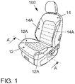
- the figure 1 1 shows a vehicle seat 100 which comprises a seat part 12 and a backrest part 14 .
- the seat part 12 and the backrest part 14 have side bolsters which are identified by the reference symbols 12A and 14A.
- FIG. 2A shows a section AA through a conventional seat part 12 of a vehicle seat 100.
- Figure 2B is the cutting plane of the section A - A according to Figure 2A drawn, with the Figure 2B shows a conventional form fleece 12-1 in a perspective view.
- the conventional molded fleece 12-1 represents a prefabricated molded part, which is also referred to as a 3D molded fleece due to its three-dimensional deformation.
- FIG. 2A includes the seat part 12, the 3D molded fleece 12-1, a foam part 12-2 and a cut foam pad 12-3.
- the pockets 12-11 form cavities that are open at the bottom in relation to the installed state of the 3D shaped fleece 12-1.
- the front side wall area in which the sports hangers are arranged in the pockets 12-11 has a length which is approximately 1/3 of the total length of a side wall 12A.
- the pre-embossed 3D form fleece 12-1 is currently placed in a foam tool and foamed, the foam tool being designed in such a way that the foam part 12-2 is foamed within the cavity of the foam tool in the foaming process, but the pockets 12-11 are not foamed with foam become.
- the tool has an insert in the area of the pockets 12-11, which ensures that the pockets 12-11 are not filled with foam.
- the form fleece 12-1 is on the edge of the foam part 12-2 (cf. Figure 2A ) is arranged and serves as a support structure for the upholstery part made at least of 3D molded fleece 12-1 and foam part 12-2.
- Sports hangers are later arranged in the cavities remaining in the pre-contoured pockets 12-11, which complete the seat part 12 in the subsequent assembly of the seat part 12.
- the in Figure 2A illustrated cut foam pad 12-3 is added, after which finally a non-illustrated reference to the foam part 12-2 and the cut foam pad 12-3 is attached, which in this embodiment form the upholstery part of the seat part 12 with the 3D molded fleece 12-1.
- the protection of the foam is necessary because when the vehicle seat 100 is in use, there is a permanent local load on the foam arranged over the sports bars.
- stiffening of the side bolsters 12A ensures that the foam of the foam part 12-2 has improved resilience in the rear area of the side bolsters 12A.
- this rigidity is also important in that improved resilience of the foam of the side panels 12A is advantageous in order to avoid wrinkling of the cover (not shown) arranged above the foam.
- the cover is made of a leather material, as is the case not only but especially with sports seats, the leather material quickly forms creases in an undesirable manner and the sports seat has an unattractive appearance if the foam of the side panels 12A is not has a certain minimum rigidity, which largely prevents the formation of wrinkles.
- This rigid foam insert is not shown in the figures, since another way has been found according to the present invention to influence the rigidity of the side panels 12A described as an example, as will be explained below.
- the Figure 3A shows a design representation as a plan view of the seat part 12 of a vehicle seat 100 according to the invention with indication of the sectional plane of a section BB along a side panel 12A'.
- Section BB lies in a sectional plane along the longitudinal extent of side panel 12A', with the sectional plane intersecting side panel 12A' in the middle.
- the sectional plane according to the section BB clarifies in a simplified representation the structure according to the invention of the foam part 12-2' and the 3D shaped fleece 12-1', which now advantageously form a support and stiffening structure in contrast to the prior art.
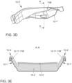
- FIG. 3B shows a plan view of the prefabricated molded part 12-1' according to the invention, indicating a sectional plane of section A'-A' transverse to section BB, which is arranged in the same sectional plane as section AA according to FIG Figure 2B .
- sectional plane in section A'-A' is also applied to the seat part 12 of the vehicle seat 100 according to the invention in the design illustration as a side view.
- FIG. 1 shows the section A′-A′ through the seat part 12 of the vehicle seat 100 according to the invention in a further construction-like view Figure 3B and 3D .
- the pockets 12-11' are designed to be longer by approximately 1/3 of the total length of the side panel 12A.
- a cavity is now also formed, which is not required for arranging the sports hangers.
- the longer pocket 12-11' is not foamed in a first section 11A' in the foaming process, while the pocket 12-11' is foamed in a second section 11B'.
- the pre-embossed 3D form fleece 12-1' is placed in a foam tool, the foam tool being designed in such a way that the foam part 12-2 ⁇ is filled with foam in the foaming process within the cavity of the foam tool, with the first section 11 A' not being filled with foam , but the second section 11B' is foamed, so that a supporting and stiffening structure of the side wall 12A is formed in the second section 11B ⁇ , which is predetermined by the outer contour of the 3D shaped fleece 12-1' and lies within the foam part 12-2 ⁇ .
- the tool has a corresponding insert part, analogous to the previous procedure, which ensures that the pocket 12-11' in the first section 11A ⁇ is not filled with foam.
- the second section 11B' of the foam part 12-2 ⁇ is according to FIG Figure 3E foamed on the contour formed by the inner surface of the 3D shaped mat 12-1' and on the contour formed by the outer surface of the 3D shaped mat 12-1' forming the pocket-like cavity 12-11' in the second portion 11B' .
- FIG 3D the foam part 12-2 ⁇ according to the invention is shown according to the outside view, in which the extended pocket 12-11' of the 3D shaped fleece 12-1' is integrated (not visible) arranged in the second section 11B'.
- the 3D molded fleece 12-1' in the second section 11B' has further openings within its lateral surface forming the pocket 12-11', in order to allow the foam to be introduced on the side facing away from the foam part 12-2' into the pocket 12-11' formed by the second portion 11B' and to affect the stiffness of the sidewall 12A ⁇ .
- the rigidity of the side walls 12A ⁇ in the second section 11B' can be influenced by forming different three-dimensional contours of the prefabricated 3D shaped fleece 12-1' and/or by forming different material thicknesses.
- the respective padding has at least one 3D molded fleece 12-1' with three-dimensional contours, which form a cavity which, during the foaming process of the foam part 12 -2 ⁇ is foamed.
Landscapes
- Engineering & Computer Science (AREA)
- Aviation & Aerospace Engineering (AREA)
- Transportation (AREA)
- Mechanical Engineering (AREA)
- Manufacturing & Machinery (AREA)
- Seats For Vehicles (AREA)
- Mattresses And Other Support Structures For Chairs And Beds (AREA)
Description
- Die Erfindung betrifft einen Fahrzeugsitz mit einem Polsterteil, welches ein Schaumteil umfasst, welches eine Stützstruktur in der Art eines Formvlieses aufweist, welches nach einem Einschäumvorgang innerhalb eines Schauprozesses mit dem Schaumteil in fester Verbindung steht.
- Die Druckschrift
US 2016/0288681 A1 beschreibt einen Fahrzeugsitz, der eine untere Sitzstruktur und eine erhöhte Sitzlehnenabstützung umfasst, wobei entweder eine der unteren Sitzstrukturen oder eine erhöhte Sitzlehnenunterstützung aus einer mehrschichtigen Anordnung besteht. Die Mehrschichtanordnung umfasst eine flexible statische Schicht, eine flexible dynamische Schicht mit einer einstellbaren Festigkeit, eine sogenannte Aufhängeschicht, die aus abstimmbaren Federn gebildet ist, die eine flexible Platte tragen, und einen Rahmenträger, der eine Schutzvertiefung enthält, in der die Aufhängungsschicht eingeschlossen ist. - Die Druckschrift
US 2013/0300178 A1 offenbart einen Fahrzeugsitz mit einem Polsterkissen, einem Flächenelement und einem starren Element. Eine Kissenauflage kann mit einem Hauptabschnitt zum Stützen eines Insassen und einem Seitenstützabschnitt versehen sein, der auf einer Seite des Hauptabschnitts vorgesehen ist. Der Seitenstützabschnitt kann von dem Hauptabschnitt vorstehen, um den Insassen zu stützen. Ein Flächenelement ist auf einer Oberfläche des Polsterkissens vorgesehen. Das starre Element ist innerhalb des seitlichen Stützabschnitts des Polsterkissens vorgesehen. Das starre Element hat eine höhere Steifigkeit als das Polsterkissen und ragt in die gleiche Richtung vor, in der der Seitenstützabschnitt vorsteht. Das starre Element weist einen Endabschnitt auf, der das Flächenelement berührt. - Außerdem ist aus der Druckschrift
DE 10 2010 011 886 A1 ein Fahrzeugsitz bekannt, der ein als Sitzkissen ausgebildetes Sitzteil aufweist, welches Seitenwangen umfasst, die jeweils in einem Hohlraum pneumatisch betätigbare Luftkammern für die Verstellung der Seitenwangen besitzt. Der Hohlraum mit den Seitenwangen ist mit einem Formvlies ausgekleidet und das Formvlies ist in einem den Luftkammern unmittelbar zugerichteten Flächenbereich mit beabstandeten Längsschlitzen versehen. Diese Längsschlitze dienen dazu, einen Verstellweg beim Aufblasen beziehungsweise beim Evakuieren zu gewährleisten. Durch das Formvlies wird das Schaumteil des Sitzkissens an den Kanten steifer, wogegen durch die bereichsweisen Längsschlitze im Formvlies das Schaumteil des Sitzkissens elastischer wird. - Ergänzend werden als weiterer Stand der Technik noch die Druckschriften
US 2007/241604 A1 ,JP 2007-50133 A KR10-2013-0027799 A JP 2016-150223 A US 2010/102599A1 genannt. Die Druckschriften beschäftigen sich mit der Versteifung von Schaumteilen, wobei insbesondere die Versteifung von Seitenwangen der Sitzteile und/oder Rückenlehnenteile jeweils im Mittelpunkt der dargestellten Lösungen liegen. - Der Erfindung liegt die Aufgabe zugrunde, eine einfache Möglichkeit zur Stabilisierung des Schaumteils eines Polsterteils einer Seitenwange zu schaffen.
- Ausgangspunkt der Erfindung ist ein Polsterteil mit einer Seitenwange, für einen Fahrzeugsitz, das zumindest ein Schaumteil umfasst, welches in einem Schäumprozess mit einem vorgefertigten Formvlies eine feste Verbindung bildet, wobei das Formflies eine Stützstruktur für das Schaumteil bildet, wobei das Formvlies mindestens einen lokal angeordneten offenen Hohlraum aufweist der abschnittsweise ausgeschäumt ist, sodass das Schaumteil zumindest in einem Abschnitt des Hohlraums des Formvlieses eine in den Schaum eingeschäumte Stütz- und Versteifungsstruktur aufweist.
- Erfindungsgemäß ist vorgesehen, dass das Formvlies einen ersten uneingeschäumten Abschnitt des Hohlraums im vorderen Bereich der Seitenwange bildet, in dem ein Sportbügel aufnehmbar ist und in einem zweiten eingeschäumten Abschnitt des Hohlraums im hinteren Bereich der Seitenwange den Schaum aufnimmt.
- Im Zusammenbauzustand sind Sportbügel für einen Fahrzeugsitz, insbesondere einen Sportfahrzeugsitz, im vorderen Bereich des Sitzteils angeordnet.
- Das Formvlies bildet die Stütz- und Versteifungsstruktur, die während des Einschäumens des Formvlieses in das Schaumteil eingeschäumt beziehungsweise umschäumt wird. Zur Umschäumung bildet das Formvlies zumindest abschnittsweise den Hohlraum, dessen Außenkontur an die Seitenwange beziehungsweise an das Schaumteil der Seitenwange angepasst ist. Der Hohlraum benötigt mindestens eine Öffnung, damit der Schaum in den Hohlraum eindringen kann.
- Ein weiterer Vorteil der Erfindung besteht darin, dass die Stütz- und Versteifungsstruktur des in dem Schaumteil integrierten Formvlieses in bevorzugter Ausgestaltung der Erfindung zumindest abschnittsweise eine dreidimensionale Kontur aufweist, die im Wesentlichen einer Kontur der Seitenwange entspricht. Der Vorteil besteht darin, dass in einfacher Weise durch entsprechende Formgebung des Formvlieses in der gewünschten Kontur abschnittsweise eine Versteifung und Abstützung des Schaumteils, insbesondere des Schaumes im Bereich der Seitenwangen ermöglicht wird.
- Bevorzugt ist vorgesehen, dass die Stütz- und Versteifungsstruktur des in dem Schaumteil integrierten Formvlieses zumindest abschnittsweise eine U-förmige dreidimensionale Kontur aufweist, die im Wesentlichen der Kontur der Seitenwange entspricht, wobei die Öffnung des Hohlraums auf einer der Oberseite der Seitenwange gegenüberliegenden Seite angeordnet ist.
- Diese Ausgestaltung hat sich als effektiv herausgestellt, dass in einfacher Weise möglich ist, den Rand des Formvlieses sozusagen mit einem U-förmigen Bord zu versehen, wodurch gleichzeitig die in der Einbaulage der Seitenwange nach unten zeigende Öffnung gebildet wird und die äußere Kontur der Seitenwange im Inneren des Schaumes nachgebildet wird.
- Es versteht sich, dass die Öffnung nicht zwingend nach unten ausgerichtet sein muss, um das Eindringen des Schaumes in den Hohlraum zu gewährleisten. Der Schaum dringt in vorteilhafter Weise auch in Längsrichtung des Hohlraums beziehungsweise in Längsrichtung der Seitenwange gesehen seitlich in den Hohlraum ein. Wesentlich ist somit, dass der Hohlraum mindestens eine Öffnung aufweist, durch die der Schaum im Schäumprozess in den Hohlraum eindringen kann.
- Es ist nämlich auch in vorteilhafter Weise vorgesehen, dass die Stütz- und Versteifungsstruktur des in dem Schaumteil integrierten Formvlieses innerhalb der Mantelfläche des Formvlieses mindestens eine Öffnung aufweist. Eine Öffnung in der Mantelfläche des Formvlieses hat den Effekt, dass sowohl der Schaum in den Hohlraum eintreten kann, als auch eine Schwächung der Stütz- und Versteifungsstruktur möglich ist. Die Anordnung einer oder mehrerer Öffnungen ist somit eine vorteilhafte Möglichkeit die Steifigkeit der Stütz- und Versteifungsstruktur zu beeinflussen. Durch Anordnung einer oder mehrerer Öffnungen in der Mantelfläche des Formvlieses wird die Steifigkeit verringert. Hinzu kommt das die Steifigkeit auch durch die Form der dreidimensionalen Stütz- und Versteifungsstruktur verändert werden kann. Zudem kann die Materialdicke des Formvlieses zumindest abschnittsweise verändert werden, sodass auch hierdurch die Steifigkeit der Stütz- und Versteifungsstruktur bedarfsweise angepasst werden kann. Es versteht sich, dass die Maßnahmen miteinander kombiniert werden können.
- Die Erfindung betrifft zudem einen Fahrzeugsitz, insbesondere den Sportfahrzeugsitz, der ein Sitzteil und ein Rückenlehnenteil umfasst, das oder die ein Polsterteil mit einer Seitenwange mit den zuvor beschriebenen Merkmalen aufweist/aufweisen.
- In der nachfolgenden Beschreibung ist eine besondere Ausführungsform eines Fahrzeugsitzes beschrieben, die einen Sportfahrzeugsitz betrifft.
- Es ist vorgesehen, dass das Polsterteil mindestens eine Seitenwange mit einer Stütz- und Versteifungsstruktur umfasst, wobei die den lokal angeordneten offenen Hohlraum aufweisende Stütz- und Versteifungsstruktur in einem ersten uneingeschäumten Abschnitt des Hohlraums der Stütz- und Versteifungsstruktur im vorderen Bereich der Seitenwange als Komponente einen Sportbügel aufnimmt, und in einem zweiten eingeschäumten Abschnitt des Hohlraums der Stütz- und Versteifungsstruktur im hinteren Bereich der Seitenwange Schaum aufnimmt. Bei einem Sportsitz übernimmt der gebildete Hohlraum sozusagen zwei Funktionen.
- In einer ersten Funktion dient der Hohlraum der Anordnung des Sportbügels.
- In einer zweiten Funktion dient der Hohlraum der Anordnung des Schaumes, sodass sich in dem hinteren Bereich der Seitenwangen eine sich hinsichtlich der Steifigkeit vom vorderen Bereich unterscheidende Anlagefläche der Seitenwange ergibt. In vorteilhafter Weise schließt sich der uneingeschäumte Abschnitt des Hohlraums an den eingeschäumten Abschnitt an.
- Bei der Herstellung des Polsterteils wird lediglich innerhalb des Werkzeuges berücksichtigt, dass ein nicht eingeschäumter Bereich vorgesehen ist, der im vorliegenden Ausführungsbeispiel für den Sportbügel vorgesehen ist, an den sich der eingeschäumte Bereich anschließt, wie in der Beschreibung näher erläutert ist.
- Die Erfindung wird nachfolgend anhand der zugehörigen Zeichnungen erläutert. Es zeigen:
- Figur 1
- einen Fahrzeugsitz;
- Figur 2A
- einen Schnitt A-A durch ein herkömmliches Sitzteil eines Fahrzeugsitzes;
- Figur 2B
- eine perspektivische Ansicht auf ein vorgefertigtes Formteil, insbesondere auf eine 3D-Formvlies, gemäß
Figur 2A ; - Figur 3A
- eine Konstruktionsdarstellung als Draufsicht auf ein Sitzteil eines erfindungsgemäßen Fahrzeugsitzes mit Angabe eines Schnittes B-B;
- Figur 3B
- eine Draufsicht auf das erfindungsgemäße vorgefertigte Formteil mit Angabe einer Schnittebene des Schnittes A' - A', der in der gleichen Schnittebene angeordnet ist, analog zu der Schnitt A - A gemäß
Figur 2B ; - Figur 3C
- eine vereinfachte Darstellung als Seitenansicht auf ein Sitzteil eines erfindungsgemäßen Fahrzeugsitzes mit Angabe eines Schnittes B - B;
- Figur 3D
- eine Konstruktionsdarstellung als Seitenansicht auf das Sitzteil des erfindungsgemäßen Fahrzeugsitzes mit Angabe des Schnittes A' - A'; und
- Figur 3E
- der Schnitt A' - A' durch das Sitzteil des erfindungsgemäßen Fahrzeugsitzes gemäß
Figur 3B und3D . - Die
Figur 1 zeigt einen Fahrzeugsitz 100, der ein Sitzteil 12 und ein Rückenlehnenteil 14 umfasst. In bekannter Weise, weisen das Sitzteil 12 und das Rückenlehnenteil 14 Seitenwangen auf, die mit den Bezugszeichen 12A und 14A gekennzeichnet sind. - Die
Figur 2A zeigt einen Schnitt A-A durch ein herkömmliches Sitzteil 12 eines Fahrzeugsitzes 100. InFigur 2B ist die Schnittebene des Schnittes A - A gemäßFigur 2A eingezeichnet, wobei dieFigur 2B ein herkömmliches Formvlies 12-1 in einer perspektivischen Ansicht zeigt. - Das herkömmliche Formvlies 12-1 stellt ein vorgefertigtes Formteil dar, welches durch seine dreidimensionale Verformung auch als 3D-Formvlies bezeichnet wird.
- Gemäß
Figur 2A umfasst das Sitzteil 12 das 3D-Formvlies 12-1, ein Schaumteil 12-2 und eine Schnittschaumauflage 12-3. - Das vorgeprägte 3D-Formvlies 12-1 umfasst derzeit zwei Taschen 12-11, die im Zusammenbauzustand zur Aufnahme von Sportbügeln dienen, die bei sogenannten Sportsitzen im vorderen Seitenwangenbereich des Sitzteils 12 als Komponenten angeordnet sind.
- Die Taschen 12-11 bilden auf den Einbauzustand des 3D-Formvlieses 12-1 bezogen nach unten geöffnete Hohlräume dar.
- Der vordere Seitenwangenbereich in dem die Sportbügel in den Taschen 12-11 angeordnet sind, weist eine Länge auf, die circa 1/3 der Gesamtlänge einer Seitenwange 12A beträgt. Derzeit wird das vorgeprägte 3D-Formvlies 12-1 in ein Schaumwerkzeug eingelegt und angeschäumt, wobei das Schaumwerkzeug derart ausgebildet ist, dass das Schaumteil 12-2 im Schäumprozess innerhalb des Hohlraums des Schaumwerkzeuges ausgeschäumt wird, jedoch die Taschen 12-11 nicht mit Schaum ausgeschäumt werden.
- Das Werkzeug weist dazu im Bereich der Taschen 12-11 ein Einsatzteil auf, welches sicherstellt, dass die Taschen 12-11 nicht mit Schaum gefüllt werden.
- Das Formvlies 12-1 ist randseitig des Schaumteils 12-2 (vgl.
Figur 2A ) angeordnet und dient als Stützstruktur für das zumindest aus 3D-Formvlies 12-1 und Schaumteil 12-2 ausgebildete Polsterteil. - In den vorkonturierten Taschen 12-11 verbleibenden Hohlräumen werden später Sportbügel angeordnet, die das Sitzteil 12 im nachfolgenden Zusammenbau des Sitzteils 12 komplettieren. Innerhalb des Zusammenbaus wird auch die in
Figur 2A dargestellte Schnittschaumauflage 12-3 hinzugefügt, wonach schließlich ein nicht näher dargestellter Bezug auf das Schaumteil 12-2 und die Schnittschaumauflage12-3 angebracht wird, die in dieser Ausführungsvariante das Polsterteil des Sitzteils 12 mit dem 3D-Formvlies 12-1 bilden. - Durch eine Zusammenschau der
Figuren 2A und 2B wird deutlich, dass die im vorher beschriebenen Schäumprozess ausgebildeten Seitenwangen 12A beziehungsweise Seitenwangen-Schaumteile 12-2 innerhalb des Schaumwerkzeuges auf der Innenseite des 3D-Formvlieses 12-1 ausgebildet beziehungsweise angeschäumt werden. - Mit anderen Worten, das herkömmliche 3D-Formvlies 12-1 sieht derzeit Vorkehrungen zur Aufnahme der Sportbügel vor und gibt durch seine Innenkontur die sitzwannenseitige Begrenzungskontur beziehungsweise Stützstruktur des Schaumteils 12-2 des Polsterteils vor. Das 3D-Formvlies 12-1 sieht bisher keine dreidimensionale Kontur vor, um eine Kontur der Seitenwangen 12A auszubilden.
- Die derzeit angeordneten Taschen 12-11 im 3D-Formvlies 12-1, zwischen Sportbügel und Schaum, dienen zum Schutz des Schaumes vor den im Zusammenbau in den Taschen 12-11 angeordneten Sportbügel. Der Schutz des Schaumes ist notwendig, da im Gebrauch des Fahrzeugsitzes 100 eine lokale Dauerbelastung des auf dem über den Sportbügeln angeordneten Schaum vorliegt.
- Von dieser Ausgestaltung des Fahrzeugsitzes 100 ausgehend, wird durch eine Versteifung der Seitenwangen 12A (Seitenwangen 14A im Rückenlehnenteil 14 analog) dafür gesorgt, dass im hinteren Bereich der Seitenwangen 12A ein verbessertes Rückstellverhalten des Schaumes des Schaumteils 12-2 vorliegt.
- Diese Steifigkeit ist neben dem Aspekt des Sitzkomforts noch dahingehend von Bedeutung, dass ein verbessertes Rückstellverhalten des Schaumes der Seitenwangen 12A von Vorteil ist, um eine Faltenbildung des oberhalb des Schaumes angeordneten Bezuges (nicht dargestellt) zu vermeiden. Insbesondere dann, wenn der Bezug aus einem Ledermaterial ausgebildet ist, wie es nicht nur aber insbesondere bei Sportsitzen der Fall ist, kommt es in nicht erwünschter Weise schnell zur Faltenbildung des Ledermaterials und zu einem unschönen Erscheinungsbild des Sportsitzes, wenn der Schaum der Seitenwangen 12A nicht eine bestimmte Mindeststeifigkeit aufweist, welche die Faltenbildung weitestgehend verhindert.
- Bei dem in den Figuren vorgestellten Fahrzeugsitz 100 handelt es sich beispielsweise um einen Sportsitz, der im vorderen Bereich (= circa 2/3 der Gesamtlänge) der Seitenwangen 12 die Sportbügel in den Taschen 12-11 des 3D-Formvlieses 12-1 aufweist, und der im hinteren Bereich (= circa 1/3 der Gesamtlänge) der Seitenwangen 12A versteifte Seitenwangen 12A aufweist, die bisher im Bedarfsfall dadurch versteift ausgebildet wurden, indem vor dem Einschäumen des 3D-Formvlieses, das heißt vor dem Schäumprozess im hinteren Bereich der auszuschäumenden Seitenwangen 12A ein sogenannter Hartschaumeinleger eingelegt wurde, der nach dem Umschäumen des Hartschaumeinlegers in das Schaumteil 12-2 integriert ist. Dieser Hartschaumeinleger ist in den Figuren nicht dargestellt, da gemäß der vorliegenden Erfindung ein anderer Weg gefunden worden ist, um die Steifigkeit der beispielhaft beschriebenen Seitenwangen 12A zu beeinflussen, wie nachfolgend erläutert wird.
- Die gemäß der Erfindung gegenüber dem Stand der Technik geänderten Bauteile sind mit Hochstrich (`) gekennzeichnet.
- Die
Figur 3A zeigt eine Konstruktionsdarstellung als Draufsicht auf das Sitzteil 12 eines erfindungsgemäßen Fahrzeugsitzes 100 mit Angabe der Schnittebene eines Schnittes B - B entlang einer Seitenwange 12A`. Der Schnitt B - B liegt in einer Schnittebene entlang der Längserstreckung der Seitenwange 12A`, wobei die Schnittebene die Seitenwange 12A` in der Mitte schneidet. Die Schnittebene gemäß dem Schnitt B - B verdeutlicht in einer vereinfachten Darstellung den erfindungsgemäßen Aufbau des Schaumteils 12-2` und des 3D-Formvlieses 12-1', die jetzt im Unterschied zum Stand der Technik in vorteilhafter Weise eine Stütz- und Versteifungsstruktur bilden. Das 3D-Formvlies 12-1' hat jetzt nicht mehr nur den Effekt, dass es das Schaumteil 12-2` stützt, sondern, dass das 3D-Formvlies 12-1' jetzt umschäumt oder mit anderen Worten im Schaum integriert angeordnet ist, wodurch das Schaumteil 12-2' zudem versteift ist. - Die
Figur 3B zeigt eine Draufsicht auf das erfindungsgemäße vorgefertigte Formteil 12-1' mit Angabe einer Schnittebene des Schnittes A' - A' quer zum Schnitt B - B, der in der gleichen Schnittebene angeordnet ist, wie der Schnitt A - A gemäßFigur 2B . - Die Schnittebene im Schnitt A' - A' ist auch in der Konstruktionsdarstellung als Seitenansicht auf das Sitzteil 12 des erfindungsgemäßen Fahrzeugsitzes 100 angetragen.
- Die
Figur 3E zeigt zur Komplettierung in einer weiteren konstruktionsartigen Ansicht den Schnitt A' - A' durch das Sitzteil 12 des erfindungsgemäßen Fahrzeugsitzes 100 gemäßFigur 3B und3D . - Es wird empfohlen bei der nachfolgenden Beschreibung die
Figuren 3A bis 3E in einer Zusammenschau zu betrachten. - In der Draufsicht gemäß
Figur 3B auf das erfindungsgemäße vorgefertigte Formteil 12-1' wird deutlich, dass die Taschen 12-11' um circa 1/3 Drittel der Gesamtlänge der Seitenwange 12A verlängert ausgebildet sind. Mit anderen Worten in der Schnittebene gemäß des Schnittes A' - A' ist jetzt ebenfalls ein Hohlraum ausgebildet, der nicht für die Anordnung der Sportbügel benötigt wird. - Bei dem beschriebenen Sportsitz ist jetzt vorgesehen, die länger ausgebildete Tasche 12-11' in einem ersten Abschnitt 11A' im Schäumprozess wie bisher nicht Auszuschäumen, während die Tasche 12-11' in einem zweiten Abschnitt 11B' ausgeschäumt wird.
- Erfindungsgemäß wird das vorgeprägte 3D-Formvlies 12-1' in ein Schaumwerkzeug eingelegt, wobei das Schaumwerkzeug derart ausgebildet ist, dass das Schaumteil 12-2` im Schäumprozess innerhalb des Hohlraums des Schaumwerkzeuges ausgeschäumt wird, wobei der erste Abschnitt 11 A' nicht ausgeschäumt wird, jedoch der zweite Abschnitt 11B' ausgeschäumt wird, sodass sich in dem zweiten Abschnitt 11B` eine durch die Außenkontur des 3D-Formvlieses 12-1' vorgegebene innerhalb des Schaumteils 12-2` liegende Stütz- und Versteifungsstruktur der Seitenwange 12A ausbildet. Das Werkzeug weist im ersten Abschnitt 11 A' analog zur bisherigen Vorgehensweise ein entsprechendes Einsatzteil auf, welche sicherstellt, dass die Tasche 12-11' im ersten Abschnitt 11A` nicht mit Schaum gefüllt wird.
- Aus
Figur 3C wird deutlich, dass das erfindungsgemäße Schaumteil 12-2` den zweiten Abschnitt 11B` aufweist, der von der Außenfläche des 3D-Formvlieses 12-1' umgriffen wird, wie am besten inFigur 3E sichtbar ist. - Der zweite Abschnitt 11B' des Schaumteils 12-2` ist gemäß
Figur 3E auf der von der Innenfläche des 3D-Formvlieses 12-1' gebildeten Kontur und auf der von der Außenfläche des 3D-Formvlieses 12-1' gebildeten Kontur, die den taschenartigen Hohlraum 12-11' im zweiten Abschnitt 11B' bildet, mit Schaum versehen. - In
Figur 3D ist gemäß der Außenansicht das erfindungsgemäße Schaumteil 12-2` dargestellt, in dem im zweiten Abschnitt 11B' die verlängerte Tasche 12-11' des 3D-Formvlieses 12-1' integriert (nicht sichtbar) angeordnet ist. - Durch Vergleich der
Figuren 2A und3B wird deutlich, dass die Seitenwange 12A` im hinteren Bereich jetzt die aus dem 3D-Formvlies 12-1' gebildete Versteifungsstruktur aufweist. - Erfindungsgemäß ist zur Optimierung des Schaumprozesses vorgesehen, dass das 3D-Formvlies 12-1' im zweiten Abschnitt 11B' innerhalb seiner die Tasche 12-11 ` bildenden Mantelfläche weitere Öffnungen aufweist, um den Schaumeintrag auf der von dem Schaumteil 12-2' abgewandten Seite in die durch den zweiten Abschnitt 11B' gebildete Tasche 12-11' zu verbessern, und um die Steifigkeit der Seitenwange 12A` zu beeinflussen.
- Erfindungsgemäß ist ferner vorgesehen, dass die Steifigkeit der Seitenwangen 12A` im zweiten Abschnitt 11B' durch Ausbildung unterschiedlicher dreidimensionaler Konturen des vorgefertigten 3D-Formvlieses 12-1' und/oder durch Ausbildung unterschiedlicher Materialstärke beeinflusst werden kann.
- Es ist somit erfindungsgemäß möglich, ein Sitzteil-Polster und/oder ein Rückenlehnenteil-Polster derart auszubilden, dass das jeweilige Polster zumindest ein 3D-Formvlies 12-1' mit dreidimensionalen Konturen aufweist, die einen Hohlraum bilden, der bei dem Schäumprozess des Schaumteils 12-2` ausgeschäumt wird.
- Dadurch lassen sich nicht nur komplette Seitenwangen oder Seitenwangenbereiche, sondern auch andere gewünschte Bereiche im Rückenlehnenteil-Polster und/oder ein Rückenlehnenteil-Polster hinsichtlich ihrer Steifigkeit anpassen. Diese Anpassung der Steifigkeit ist in vorteilhafter Weise möglich, ohne dass beispielsweise für diese Bereiche ein anderer Schaum eingesetzt werden muss, um die Steifigkeit anzupassen. Die erforderlichen Maßnahmen zur Konturanpassung des 3D-Formvlieses 12-1' und des Werkzeuges sind unter Berücksichtigung einer Serienherstellung mit hohen Stückzahlen gering.
-
- 100
- Fahrzeugsitz
- 12
- Sitzteil
- 12-3
- Schnittschaumauflage
- 14
- Rückenlehnenteil
-
- 12A
- Seitenwange
- 12-1
- Formvlies, 3D-Formvlies als Stützstruktur
- 12-11
- Hohlraum, Tasche (nicht eingeschäumt)
- 12-2
- Schaumteil
-
- 12A`
- Seitenwange
- 12-1'
- Formvlies, 3D-Formvlies als Stütz- und Versteifungsstruktur
- 12-11'
- Hohlraum, Tasche
- 11A'
- erster Abschnitt der Tasche
- 11B'
- zweiter Abschnitt der Tasche (eingeschäumt)
- 12-2`
- Schaumteil
Claims (5)
- Polsterteil mit einer Seitenwange (12A'), für einen Fahrzeugsitz, zumindest umfassend ein Schaumteil (12-2'), welches in einem Schäumprozess mit einem vorgefertigten Formvlies (12-1') eine feste Verbindung bildet, wobei das Formflies (12-1') eine Stützstruktur für das Schaumteil (12-2') bildet, wobei das Formvlies (12-1 `) mindestens einen lokal angeordneten offenen Hohlraum (12-11') aufweist, der zumindest abschnittsweise ausgeschäumt ist, sodass das Schaumteil (12-2') zumindest in einem Abschnitt (11B') des Hohlraums (12-11') des Formvlieses (12-1') eine in den Schaum eingeschäumte Stütz- und Versteifungsstruktur aufweist, dadurch gekennzeichnet, dass das Formvlies (12-1') einen ersten uneingeschäumten Abschnitt (11A') des Hohlraums (12-11`) im vorderen Bereich der Seitenwange (12A') bildet, in dem ein Sportbügel aufnehmbar ist und in einem zweiten eingeschäumten Abschnitt (11B') des Hohlraums (12-11') im hinteren Bereich der Seitenwange (12A') den Schaum aufnimmt.
- Polsterteil mit einer Seitenwange (12A') nach Anspruch 1, dadurch gekennzeichnet, dass das Formvlies (12-1') zumindest abschnittsweise eine dreidimensionale Kontur aufweist, die im Wesentlichen einer Kontur der Seitenwange (12A') entspricht.
- Polsterteil mit einer Seitenwange (12A') nach den Ansprüchen 1 und 2, dadurch gekennzeichnet, dass das Formvlies (12-1') zumindest abschnittsweise eine U-förmige dreidimensionale Kontur aufweist, die im Wesentlichen der Kontur der Seitenwange (12A') entspricht, wobei die Öffnung des Hohlraums (12-11') auf einer der Oberseite der Seitenwange (12A`) gegenüberliegenden Seite angeordnet ist.
- Polsterteil mit einer Seitenwange (12A') nach Anspruch 1, dadurch gekennzeichnet, dass das Formvlies (12-1') innerhalb der Mantelfläche des Formvlieses (12-1') mindestens eine Öffnung aufweist.
- Fahrzeugsitz (100) umfassend ein Sitzteil (12) und ein Rückenlehnenteil (14), das oder die ein Polsterteil mit einer Seitenwange (12A') nach mindestens einem der Ansprüche 1 bis 4 aufweist/aufweisen.
Applications Claiming Priority (2)
| Application Number | Priority Date | Filing Date | Title |
|---|---|---|---|
| DE102017113098.5A DE102017113098A1 (de) | 2017-06-14 | 2017-06-14 | Polsterteil eines Fahrzeugsitzes mit einem umschäumten 3D-Formvlies zur Versteifung einer Seitenwange |
| PCT/EP2018/065803 WO2018229185A1 (de) | 2017-06-14 | 2018-06-14 | Polsterteil eines fahrzeugsitzes mit einem umschäumten 3d-formvlies zur versteifung einer seitenwange |
Publications (2)
| Publication Number | Publication Date |
|---|---|
| EP3638537A1 EP3638537A1 (de) | 2020-04-22 |
| EP3638537B1 true EP3638537B1 (de) | 2023-04-05 |
Family
ID=62620888
Family Applications (1)
| Application Number | Title | Priority Date | Filing Date |
|---|---|---|---|
| EP18731443.0A Active EP3638537B1 (de) | 2017-06-14 | 2018-06-14 | Polsterteil eines fahrzeugsitzes mit einem umschäumten 3d-formvlies zur versteifung einer seitenwange |
Country Status (5)
| Country | Link |
|---|---|
| US (1) | US11192480B2 (de) |
| EP (1) | EP3638537B1 (de) |
| CN (1) | CN111065545B (de) |
| DE (1) | DE102017113098A1 (de) |
| WO (1) | WO2018229185A1 (de) |
Families Citing this family (4)
| Publication number | Priority date | Publication date | Assignee | Title |
|---|---|---|---|---|
| DE102020119703A1 (de) | 2020-07-27 | 2022-01-27 | Jürgen Vauth | Strukturteil für einen Fahrzeugsitz, insbesondere Flugzeugsitz und Fahrzeugsitz, insbesondere Flugzeugsitz |
| DE102021102229A1 (de) * | 2020-09-29 | 2022-03-31 | Adient Engineering and IP GmbH | Schaumteil, insbesondere für einen Fahrzeugsitz, Verfahren zur Herstellung eines Schaumteils, sowie Fahrzeugsitz |
| CN113103567B (zh) * | 2021-04-08 | 2022-10-11 | 上海工程技术大学 | 一种基于异质材料3d打印技术的座椅面套及其形成方法 |
| WO2023047299A1 (de) * | 2021-09-22 | 2023-03-30 | Adient Us Llc | Sitz mit einem nachrüstbaren anbauelement |
Family Cites Families (17)
| Publication number | Priority date | Publication date | Assignee | Title |
|---|---|---|---|---|
| JPH0899638A (ja) | 1994-08-05 | 1996-04-16 | Aprica Kassai Inc | 育児器具の座席 |
| DE4430283C2 (de) * | 1994-08-26 | 1996-07-18 | Daimler Benz Ag | Kraftwagensitz mit einer von einem Rahmen eingefaßten Stützfläche |
| FR2836470B1 (fr) | 2002-02-25 | 2004-07-09 | J S O | Matelassure en mousse de melanine et ses applications |
| EP1915927B1 (de) * | 2005-08-18 | 2011-03-30 | Bridgestone Corporation | Fahrzeugsitzunterlage |
| JP5017816B2 (ja) | 2005-08-18 | 2012-09-05 | 株式会社ブリヂストン | 車両用シートパッド |
| US7661764B2 (en) * | 2006-08-30 | 2010-02-16 | Lear Corporation | Vehicle seat assembly having a hardness gradient via “A” surface intrusions and/or protrusions |
| JP5349906B2 (ja) | 2008-10-29 | 2013-11-20 | トヨタ紡織株式会社 | 車両用シートのクッション構造体 |
| JP5463903B2 (ja) | 2009-12-24 | 2014-04-09 | トヨタ紡織株式会社 | 車両用シートのクッション材 |
| DE102010011886B4 (de) | 2010-03-18 | 2023-08-24 | Dr. Ing. H.C. F. Porsche Aktiengesellschaft | Kraftfahrzeugsitz |
| KR101738021B1 (ko) | 2011-09-08 | 2017-05-19 | 현대자동차주식회사 | 차량 시트용 이경도 패드 |
| DE102011119059B4 (de) * | 2011-11-14 | 2016-10-20 | Prevent Dev Gmbh | Sitzkissen |
| JP2013233287A (ja) | 2012-05-09 | 2013-11-21 | Toyota Boshoku Corp | 車両用シート |
| US9138062B2 (en) * | 2013-02-22 | 2015-09-22 | Mark Todd | Molded seat |
| JP5976511B2 (ja) * | 2012-11-26 | 2016-08-23 | 東洋ゴム工業株式会社 | シートパッド |
| JP6517036B2 (ja) | 2015-02-19 | 2019-05-22 | 株式会社イノアックコーポレーション | 車両用シートパッド及びその製造方法 |
| US9802521B2 (en) | 2015-03-31 | 2017-10-31 | Ford Global Technologies, Llp | Multilayer seat |
| JP6761768B2 (ja) * | 2017-02-28 | 2020-09-30 | 株式会社ジェイエスピー | 車両用シートクッション芯材 |
-
2017
- 2017-06-14 DE DE102017113098.5A patent/DE102017113098A1/de not_active Withdrawn
-
2018
- 2018-06-14 EP EP18731443.0A patent/EP3638537B1/de active Active
- 2018-06-14 WO PCT/EP2018/065803 patent/WO2018229185A1/de not_active Ceased
- 2018-06-14 US US16/621,469 patent/US11192480B2/en active Active
- 2018-06-14 CN CN201880040133.8A patent/CN111065545B/zh active Active
Also Published As
| Publication number | Publication date |
|---|---|
| US11192480B2 (en) | 2021-12-07 |
| DE102017113098A1 (de) | 2018-12-20 |
| CN111065545B (zh) | 2022-05-31 |
| US20200171991A1 (en) | 2020-06-04 |
| EP3638537A1 (de) | 2020-04-22 |
| WO2018229185A1 (de) | 2018-12-20 |
| CN111065545A (zh) | 2020-04-24 |
Similar Documents
| Publication | Publication Date | Title |
|---|---|---|
| EP2941366B1 (de) | Schaumteil, insbesondere für einen fahrzeugsitz, sowie verfahren und werkzeug zur herstellung eines schaumteils | |
| EP3638537B1 (de) | Polsterteil eines fahrzeugsitzes mit einem umschäumten 3d-formvlies zur versteifung einer seitenwange | |
| EP3083327B1 (de) | Schaumteil, insbesondere für einen fahrzeugsitz und fahrzeugsitz | |
| DE102014220740B4 (de) | Modularer verbundrahmen für eine hintere sitzkonstruktion | |
| DE69405487T2 (de) | Polster für Kraftfahrzeugsitze | |
| DE102013202688B4 (de) | Sitzkissen für einen Fahrzeugsitz | |
| DE102008060993A1 (de) | Geschichtetes Sitzpolster mit gerichteter Durchbiegung für Kindersitz und Insassensicherheit | |
| EP3250400B1 (de) | Leichtbausitz für fahrzeuge | |
| EP2511127B1 (de) | Kopfstütze für Fahrzeugsitze | |
| DE102015121089A1 (de) | Energieabsorbierende zusammenklappbare Armlehne mit einstellbarem Versteifungsmerkmal | |
| WO2022069504A1 (de) | Schaumteil, insbesondere für einen fahrzeugsitz, verfahren zur herstellung eines schaumteils, sowie fahrzeugsitz | |
| WO2015086765A1 (de) | Sitzteil und fahrzeugsitz | |
| DE102016212222B4 (de) | Fahrzeugsitz | |
| DE102018125732A1 (de) | Sitzbaugruppe mit einer modularen schaumanordnung und herstellungsverfahren dafür | |
| EP1268153A1 (de) | Schaumteil und verfahren zu seiner herstellung | |
| EP3463974B1 (de) | Sitzlehnenverkleidung und verfahren zu deren herstellung | |
| DE102019113342A1 (de) | Waffelbrettstrukturierte b-oberfläche für sitzpolster | |
| DE10009941A1 (de) | Schaumteil mit eingeschäumtem elastischen Einlegeteil | |
| DE102010011886B4 (de) | Kraftfahrzeugsitz | |
| DE19906987B4 (de) | Rahmen für die Rückenlehne eines Fahrzeugsitzes | |
| DE102008011246A1 (de) | Fahrzeugsitz, insbesondere Kraftfahrzeugsitz | |
| EP3817968A1 (de) | Fahrradsattel sowie verfahren zur herstellung eines polsterelements für einen fahrradsattel | |
| DE102017222015A1 (de) | Verkleidungselement zur Verkleidung einer Seitenfläche eines Fahrzeuginnenraums | |
| DE1630981A1 (de) | Schutzpolster | |
| DE2703866A1 (de) | Kopfstuetze fuer kraftfahrzeugsitze |
Legal Events
| Date | Code | Title | Description |
|---|---|---|---|
| STAA | Information on the status of an ep patent application or granted ep patent |
Free format text: STATUS: UNKNOWN |
|
| STAA | Information on the status of an ep patent application or granted ep patent |
Free format text: STATUS: THE INTERNATIONAL PUBLICATION HAS BEEN MADE |
|
| PUAI | Public reference made under article 153(3) epc to a published international application that has entered the european phase |
Free format text: ORIGINAL CODE: 0009012 |
|
| STAA | Information on the status of an ep patent application or granted ep patent |
Free format text: STATUS: REQUEST FOR EXAMINATION WAS MADE |
|
| 17P | Request for examination filed |
Effective date: 20200110 |
|
| AK | Designated contracting states |
Kind code of ref document: A1 Designated state(s): AL AT BE BG CH CY CZ DE DK EE ES FI FR GB GR HR HU IE IS IT LI LT LU LV MC MK MT NL NO PL PT RO RS SE SI SK SM TR |
|
| AX | Request for extension of the european patent |
Extension state: BA ME |
|
| DAV | Request for validation of the european patent (deleted) | ||
| DAX | Request for extension of the european patent (deleted) | ||
| STAA | Information on the status of an ep patent application or granted ep patent |
Free format text: STATUS: EXAMINATION IS IN PROGRESS |
|
| 17Q | First examination report despatched |
Effective date: 20210728 |
|
| GRAP | Despatch of communication of intention to grant a patent |
Free format text: ORIGINAL CODE: EPIDOSNIGR1 |
|
| STAA | Information on the status of an ep patent application or granted ep patent |
Free format text: STATUS: GRANT OF PATENT IS INTENDED |
|
| INTG | Intention to grant announced |
Effective date: 20221021 |
|
| GRAS | Grant fee paid |
Free format text: ORIGINAL CODE: EPIDOSNIGR3 |
|
| GRAA | (expected) grant |
Free format text: ORIGINAL CODE: 0009210 |
|
| STAA | Information on the status of an ep patent application or granted ep patent |
Free format text: STATUS: THE PATENT HAS BEEN GRANTED |
|
| REG | Reference to a national code |
Ref country code: DE Ref legal event code: R081 Ref document number: 502018011905 Country of ref document: DE Owner name: PROSEAT GMBH & CO. KG, DE Free format text: FORMER OWNER: SITECH SITZTECHNIK GMBH, 38442 WOLFSBURG, DE Ref country code: DE Ref legal event code: R081 Ref document number: 502018011905 Country of ref document: DE Owner name: BROSE SITECH GMBH, DE Free format text: FORMER OWNER: SITECH SITZTECHNIK GMBH, 38442 WOLFSBURG, DE |
|
| AK | Designated contracting states |
Kind code of ref document: B1 Designated state(s): AL AT BE BG CH CY CZ DE DK EE ES FI FR GB GR HR HU IE IS IT LI LT LU LV MC MK MT NL NO PL PT RO RS SE SI SK SM TR |
|
| REG | Reference to a national code |
Ref country code: GB Ref legal event code: FG4D Free format text: NOT ENGLISH |
|
| REG | Reference to a national code |
Ref country code: CH Ref legal event code: EP |
|
| REG | Reference to a national code |
Ref country code: AT Ref legal event code: REF Ref document number: 1557993 Country of ref document: AT Kind code of ref document: T Effective date: 20230415 |
|
| REG | Reference to a national code |
Ref country code: DE Ref legal event code: R096 Ref document number: 502018011905 Country of ref document: DE |
|
| REG | Reference to a national code |
Ref country code: IE Ref legal event code: FG4D Free format text: LANGUAGE OF EP DOCUMENT: GERMAN |
|
| P01 | Opt-out of the competence of the unified patent court (upc) registered |
Effective date: 20230508 |
|
| REG | Reference to a national code |
Ref country code: DE Ref legal event code: R081 Ref document number: 502018011905 Country of ref document: DE Owner name: PROSEAT GMBH & CO. KG, DE Free format text: FORMER OWNERS: PROSEAT GMBH & CO. KG, 64546 MOERFELDEN-WALLDORF, DE; SITECH SITZTECHNIK GMBH, 38442 WOLFSBURG, DE Ref country code: DE Ref legal event code: R081 Ref document number: 502018011905 Country of ref document: DE Owner name: BROSE SITECH GMBH, DE Free format text: FORMER OWNERS: PROSEAT GMBH & CO. KG, 64546 MOERFELDEN-WALLDORF, DE; SITECH SITZTECHNIK GMBH, 38442 WOLFSBURG, DE |
|
| REG | Reference to a national code |
Ref country code: LT Ref legal event code: MG9D |
|
| RAP4 | Party data changed (patent owner data changed or rights of a patent transferred) |
Owner name: PROSEAT GMBH & CO. KG Owner name: BROSE SITECH GMBH |
|
| REG | Reference to a national code |
Ref country code: NL Ref legal event code: MP Effective date: 20230405 |
|
| PG25 | Lapsed in a contracting state [announced via postgrant information from national office to epo] |
Ref country code: NL Free format text: LAPSE BECAUSE OF FAILURE TO SUBMIT A TRANSLATION OF THE DESCRIPTION OR TO PAY THE FEE WITHIN THE PRESCRIBED TIME-LIMIT Effective date: 20230405 |
|
| PG25 | Lapsed in a contracting state [announced via postgrant information from national office to epo] |
Ref country code: SE Free format text: LAPSE BECAUSE OF FAILURE TO SUBMIT A TRANSLATION OF THE DESCRIPTION OR TO PAY THE FEE WITHIN THE PRESCRIBED TIME-LIMIT Effective date: 20230405 Ref country code: PT Free format text: LAPSE BECAUSE OF FAILURE TO SUBMIT A TRANSLATION OF THE DESCRIPTION OR TO PAY THE FEE WITHIN THE PRESCRIBED TIME-LIMIT Effective date: 20230807 Ref country code: NO Free format text: LAPSE BECAUSE OF FAILURE TO SUBMIT A TRANSLATION OF THE DESCRIPTION OR TO PAY THE FEE WITHIN THE PRESCRIBED TIME-LIMIT Effective date: 20230705 Ref country code: ES Free format text: LAPSE BECAUSE OF FAILURE TO SUBMIT A TRANSLATION OF THE DESCRIPTION OR TO PAY THE FEE WITHIN THE PRESCRIBED TIME-LIMIT Effective date: 20230405 |
|
| PG25 | Lapsed in a contracting state [announced via postgrant information from national office to epo] |
Ref country code: RS Free format text: LAPSE BECAUSE OF FAILURE TO SUBMIT A TRANSLATION OF THE DESCRIPTION OR TO PAY THE FEE WITHIN THE PRESCRIBED TIME-LIMIT Effective date: 20230405 Ref country code: PL Free format text: LAPSE BECAUSE OF FAILURE TO SUBMIT A TRANSLATION OF THE DESCRIPTION OR TO PAY THE FEE WITHIN THE PRESCRIBED TIME-LIMIT Effective date: 20230405 Ref country code: LV Free format text: LAPSE BECAUSE OF FAILURE TO SUBMIT A TRANSLATION OF THE DESCRIPTION OR TO PAY THE FEE WITHIN THE PRESCRIBED TIME-LIMIT Effective date: 20230405 Ref country code: LT Free format text: LAPSE BECAUSE OF FAILURE TO SUBMIT A TRANSLATION OF THE DESCRIPTION OR TO PAY THE FEE WITHIN THE PRESCRIBED TIME-LIMIT Effective date: 20230405 Ref country code: IS Free format text: LAPSE BECAUSE OF FAILURE TO SUBMIT A TRANSLATION OF THE DESCRIPTION OR TO PAY THE FEE WITHIN THE PRESCRIBED TIME-LIMIT Effective date: 20230805 Ref country code: HR Free format text: LAPSE BECAUSE OF FAILURE TO SUBMIT A TRANSLATION OF THE DESCRIPTION OR TO PAY THE FEE WITHIN THE PRESCRIBED TIME-LIMIT Effective date: 20230405 Ref country code: GR Free format text: LAPSE BECAUSE OF FAILURE TO SUBMIT A TRANSLATION OF THE DESCRIPTION OR TO PAY THE FEE WITHIN THE PRESCRIBED TIME-LIMIT Effective date: 20230706 Ref country code: AL Free format text: LAPSE BECAUSE OF FAILURE TO SUBMIT A TRANSLATION OF THE DESCRIPTION OR TO PAY THE FEE WITHIN THE PRESCRIBED TIME-LIMIT Effective date: 20230405 |
|
| PG25 | Lapsed in a contracting state [announced via postgrant information from national office to epo] |
Ref country code: FI Free format text: LAPSE BECAUSE OF FAILURE TO SUBMIT A TRANSLATION OF THE DESCRIPTION OR TO PAY THE FEE WITHIN THE PRESCRIBED TIME-LIMIT Effective date: 20230405 |
|
| REG | Reference to a national code |
Ref country code: DE Ref legal event code: R097 Ref document number: 502018011905 Country of ref document: DE |
|
| PG25 | Lapsed in a contracting state [announced via postgrant information from national office to epo] |
Ref country code: SK Free format text: LAPSE BECAUSE OF FAILURE TO SUBMIT A TRANSLATION OF THE DESCRIPTION OR TO PAY THE FEE WITHIN THE PRESCRIBED TIME-LIMIT Effective date: 20230405 |
|
| PG25 | Lapsed in a contracting state [announced via postgrant information from national office to epo] |
Ref country code: MC Free format text: LAPSE BECAUSE OF FAILURE TO SUBMIT A TRANSLATION OF THE DESCRIPTION OR TO PAY THE FEE WITHIN THE PRESCRIBED TIME-LIMIT Effective date: 20230405 |
|
| PG25 | Lapsed in a contracting state [announced via postgrant information from national office to epo] |
Ref country code: SM Free format text: LAPSE BECAUSE OF FAILURE TO SUBMIT A TRANSLATION OF THE DESCRIPTION OR TO PAY THE FEE WITHIN THE PRESCRIBED TIME-LIMIT Effective date: 20230405 Ref country code: SK Free format text: LAPSE BECAUSE OF FAILURE TO SUBMIT A TRANSLATION OF THE DESCRIPTION OR TO PAY THE FEE WITHIN THE PRESCRIBED TIME-LIMIT Effective date: 20230405 Ref country code: RO Free format text: LAPSE BECAUSE OF FAILURE TO SUBMIT A TRANSLATION OF THE DESCRIPTION OR TO PAY THE FEE WITHIN THE PRESCRIBED TIME-LIMIT Effective date: 20230405 Ref country code: MC Free format text: LAPSE BECAUSE OF FAILURE TO SUBMIT A TRANSLATION OF THE DESCRIPTION OR TO PAY THE FEE WITHIN THE PRESCRIBED TIME-LIMIT Effective date: 20230405 Ref country code: EE Free format text: LAPSE BECAUSE OF FAILURE TO SUBMIT A TRANSLATION OF THE DESCRIPTION OR TO PAY THE FEE WITHIN THE PRESCRIBED TIME-LIMIT Effective date: 20230405 Ref country code: DK Free format text: LAPSE BECAUSE OF FAILURE TO SUBMIT A TRANSLATION OF THE DESCRIPTION OR TO PAY THE FEE WITHIN THE PRESCRIBED TIME-LIMIT Effective date: 20230405 Ref country code: CZ Free format text: LAPSE BECAUSE OF FAILURE TO SUBMIT A TRANSLATION OF THE DESCRIPTION OR TO PAY THE FEE WITHIN THE PRESCRIBED TIME-LIMIT Effective date: 20230405 |
|
| REG | Reference to a national code |
Ref country code: CH Ref legal event code: PL |
|
| PLBE | No opposition filed within time limit |
Free format text: ORIGINAL CODE: 0009261 |
|
| STAA | Information on the status of an ep patent application or granted ep patent |
Free format text: STATUS: NO OPPOSITION FILED WITHIN TIME LIMIT |
|
| REG | Reference to a national code |
Ref country code: BE Ref legal event code: MM Effective date: 20230630 |
|
| PG25 | Lapsed in a contracting state [announced via postgrant information from national office to epo] |
Ref country code: LU Free format text: LAPSE BECAUSE OF NON-PAYMENT OF DUE FEES Effective date: 20230614 |
|
| 26N | No opposition filed |
Effective date: 20240108 |
|
| GBPC | Gb: european patent ceased through non-payment of renewal fee |
Effective date: 20230705 |
|
| REG | Reference to a national code |
Ref country code: IE Ref legal event code: MM4A |
|
| PG25 | Lapsed in a contracting state [announced via postgrant information from national office to epo] |
Ref country code: LU Free format text: LAPSE BECAUSE OF NON-PAYMENT OF DUE FEES Effective date: 20230614 |
|
| PG25 | Lapsed in a contracting state [announced via postgrant information from national office to epo] |
Ref country code: IE Free format text: LAPSE BECAUSE OF NON-PAYMENT OF DUE FEES Effective date: 20230614 |
|
| PG25 | Lapsed in a contracting state [announced via postgrant information from national office to epo] |
Ref country code: IE Free format text: LAPSE BECAUSE OF NON-PAYMENT OF DUE FEES Effective date: 20230614 Ref country code: GB Free format text: LAPSE BECAUSE OF NON-PAYMENT OF DUE FEES Effective date: 20230705 Ref country code: CH Free format text: LAPSE BECAUSE OF NON-PAYMENT OF DUE FEES Effective date: 20230630 |
|
| PG25 | Lapsed in a contracting state [announced via postgrant information from national office to epo] |
Ref country code: SI Free format text: LAPSE BECAUSE OF FAILURE TO SUBMIT A TRANSLATION OF THE DESCRIPTION OR TO PAY THE FEE WITHIN THE PRESCRIBED TIME-LIMIT Effective date: 20230405 |
|
| PG25 | Lapsed in a contracting state [announced via postgrant information from national office to epo] |
Ref country code: SI Free format text: LAPSE BECAUSE OF FAILURE TO SUBMIT A TRANSLATION OF THE DESCRIPTION OR TO PAY THE FEE WITHIN THE PRESCRIBED TIME-LIMIT Effective date: 20230405 Ref country code: IT Free format text: LAPSE BECAUSE OF FAILURE TO SUBMIT A TRANSLATION OF THE DESCRIPTION OR TO PAY THE FEE WITHIN THE PRESCRIBED TIME-LIMIT Effective date: 20230405 Ref country code: FR Free format text: LAPSE BECAUSE OF NON-PAYMENT OF DUE FEES Effective date: 20230630 Ref country code: BE Free format text: LAPSE BECAUSE OF NON-PAYMENT OF DUE FEES Effective date: 20230630 |
|
| REG | Reference to a national code |
Ref country code: AT Ref legal event code: MM01 Ref document number: 1557993 Country of ref document: AT Kind code of ref document: T Effective date: 20230614 |
|
| PG25 | Lapsed in a contracting state [announced via postgrant information from national office to epo] |
Ref country code: AT Free format text: LAPSE BECAUSE OF NON-PAYMENT OF DUE FEES Effective date: 20230614 |
|
| PG25 | Lapsed in a contracting state [announced via postgrant information from national office to epo] |
Ref country code: AT Free format text: LAPSE BECAUSE OF NON-PAYMENT OF DUE FEES Effective date: 20230614 |
|
| PG25 | Lapsed in a contracting state [announced via postgrant information from national office to epo] |
Ref country code: BG Free format text: LAPSE BECAUSE OF FAILURE TO SUBMIT A TRANSLATION OF THE DESCRIPTION OR TO PAY THE FEE WITHIN THE PRESCRIBED TIME-LIMIT Effective date: 20230405 |
|
| PG25 | Lapsed in a contracting state [announced via postgrant information from national office to epo] |
Ref country code: BG Free format text: LAPSE BECAUSE OF FAILURE TO SUBMIT A TRANSLATION OF THE DESCRIPTION OR TO PAY THE FEE WITHIN THE PRESCRIBED TIME-LIMIT Effective date: 20230405 |
|
| PG25 | Lapsed in a contracting state [announced via postgrant information from national office to epo] |
Ref country code: CY Free format text: LAPSE BECAUSE OF FAILURE TO SUBMIT A TRANSLATION OF THE DESCRIPTION OR TO PAY THE FEE WITHIN THE PRESCRIBED TIME-LIMIT; INVALID AB INITIO Effective date: 20180614 |
|
| PG25 | Lapsed in a contracting state [announced via postgrant information from national office to epo] |
Ref country code: HU Free format text: LAPSE BECAUSE OF FAILURE TO SUBMIT A TRANSLATION OF THE DESCRIPTION OR TO PAY THE FEE WITHIN THE PRESCRIBED TIME-LIMIT; INVALID AB INITIO Effective date: 20180614 |
|
| PGFP | Annual fee paid to national office [announced via postgrant information from national office to epo] |
Ref country code: DE Payment date: 20250626 Year of fee payment: 8 |
|
| PG25 | Lapsed in a contracting state [announced via postgrant information from national office to epo] |
Ref country code: TR Free format text: LAPSE BECAUSE OF FAILURE TO SUBMIT A TRANSLATION OF THE DESCRIPTION OR TO PAY THE FEE WITHIN THE PRESCRIBED TIME-LIMIT Effective date: 20230405 |