EP3638434B1 - Matrizenwechsel-vorrichtung und -verfahren - Google Patents
Matrizenwechsel-vorrichtung und -verfahren Download PDFInfo
- Publication number
- EP3638434B1 EP3638434B1 EP18734903.0A EP18734903A EP3638434B1 EP 3638434 B1 EP3638434 B1 EP 3638434B1 EP 18734903 A EP18734903 A EP 18734903A EP 3638434 B1 EP3638434 B1 EP 3638434B1
- Authority
- EP
- European Patent Office
- Prior art keywords
- die
- support
- conduit
- waste
- supporting portion
- Prior art date
- Legal status (The legal status is an assumption and is not a legal conclusion. Google has not performed a legal analysis and makes no representation as to the accuracy of the status listed.)
- Active
Links
Images




Classifications
-
- B—PERFORMING OPERATIONS; TRANSPORTING
- B21—MECHANICAL METAL-WORKING WITHOUT ESSENTIALLY REMOVING MATERIAL; PUNCHING METAL
- B21J—FORGING; HAMMERING; PRESSING METAL; RIVETING; FORGE FURNACES
- B21J15/00—Riveting
- B21J15/10—Riveting machines
- B21J15/36—Rivet sets, i.e. tools for forming heads; Mandrels for expanding parts of hollow rivets
-
- B—PERFORMING OPERATIONS; TRANSPORTING
- B21—MECHANICAL METAL-WORKING WITHOUT ESSENTIALLY REMOVING MATERIAL; PUNCHING METAL
- B21J—FORGING; HAMMERING; PRESSING METAL; RIVETING; FORGE FURNACES
- B21J15/00—Riveting
- B21J15/02—Riveting procedures
- B21J15/025—Setting self-piercing rivets
-
- B—PERFORMING OPERATIONS; TRANSPORTING
- B21—MECHANICAL METAL-WORKING WITHOUT ESSENTIALLY REMOVING MATERIAL; PUNCHING METAL
- B21J—FORGING; HAMMERING; PRESSING METAL; RIVETING; FORGE FURNACES
- B21J15/00—Riveting
- B21J15/10—Riveting machines
- B21J15/14—Riveting machines specially adapted for riveting specific articles, e.g. brake lining machines
-
- B—PERFORMING OPERATIONS; TRANSPORTING
- B21—MECHANICAL METAL-WORKING WITHOUT ESSENTIALLY REMOVING MATERIAL; PUNCHING METAL
- B21J—FORGING; HAMMERING; PRESSING METAL; RIVETING; FORGE FURNACES
- B21J15/00—Riveting
- B21J15/10—Riveting machines
- B21J15/30—Particular elements, e.g. supports; Suspension equipment specially adapted for portable riveters
-
- Y—GENERAL TAGGING OF NEW TECHNOLOGICAL DEVELOPMENTS; GENERAL TAGGING OF CROSS-SECTIONAL TECHNOLOGIES SPANNING OVER SEVERAL SECTIONS OF THE IPC; TECHNICAL SUBJECTS COVERED BY FORMER USPC CROSS-REFERENCE ART COLLECTIONS [XRACs] AND DIGESTS
- Y10—TECHNICAL SUBJECTS COVERED BY FORMER USPC
- Y10T—TECHNICAL SUBJECTS COVERED BY FORMER US CLASSIFICATION
- Y10T29/00—Metal working
- Y10T29/49—Method of mechanical manufacture
- Y10T29/49826—Assembling or joining
- Y10T29/49908—Joining by deforming
- Y10T29/49938—Radially expanding part in cavity, aperture, or hollow body
- Y10T29/49943—Riveting
-
- Y—GENERAL TAGGING OF NEW TECHNOLOGICAL DEVELOPMENTS; GENERAL TAGGING OF CROSS-SECTIONAL TECHNOLOGIES SPANNING OVER SEVERAL SECTIONS OF THE IPC; TECHNICAL SUBJECTS COVERED BY FORMER USPC CROSS-REFERENCE ART COLLECTIONS [XRACs] AND DIGESTS
- Y10—TECHNICAL SUBJECTS COVERED BY FORMER USPC
- Y10T—TECHNICAL SUBJECTS COVERED BY FORMER US CLASSIFICATION
- Y10T29/00—Metal working
- Y10T29/49—Method of mechanical manufacture
- Y10T29/49826—Assembling or joining
- Y10T29/49947—Assembling or joining by applying separate fastener
- Y10T29/49954—Fastener deformed after application
- Y10T29/49956—Riveting
-
- Y—GENERAL TAGGING OF NEW TECHNOLOGICAL DEVELOPMENTS; GENERAL TAGGING OF CROSS-SECTIONAL TECHNOLOGIES SPANNING OVER SEVERAL SECTIONS OF THE IPC; TECHNICAL SUBJECTS COVERED BY FORMER USPC CROSS-REFERENCE ART COLLECTIONS [XRACs] AND DIGESTS
- Y10—TECHNICAL SUBJECTS COVERED BY FORMER USPC
- Y10T—TECHNICAL SUBJECTS COVERED BY FORMER US CLASSIFICATION
- Y10T29/00—Metal working
- Y10T29/53—Means to assemble or disassemble
- Y10T29/5343—Means to drive self-piercing work part
Definitions
- the present invention relates to a die changing apparatus, and, in particular, to a die changing apparatus which may form part of a fastening apparatus.
- the fastening apparatus may be a rivet setter which utilises self-piercing rivets.
- the invention also relates to associated methods.
- fastener which are used to secure two or more portions of a workpiece (for example, two or more sheets) together.
- One group of such known fasteners functions as follows.
- a fastener support is placed beneath the workpiece, and a fastener and fastener insertion device are located above both the fastener support and the workpiece.
- the fastener insertion device applies a force to the fastener to thereby drive the fastener through the workpiece towards the fastener support.
- the fastener support may exert a reaction force on the fastener as a result of a force applied to the fastener by the fastener insertion device.
- the forces acting on the fastener may cause the fastener to deform and thereby secure the two or more portions of the workpiece together.
- fasteners examples include rivets, mechanical studs and other types of fastening devices.
- a particular type of known rivet is the self-piercing rivet.
- the use of such rivets in conjunction with suitable adhesives or otherwise has become widespread and desirable in industries in which welding is not practical.
- Such industries include industries which utilise aluminium components.
- One example of such an industry is the automotive industry in which stacks of metal sheets, including at least one aluminium sheet, may need to be fastened together.
- known fastening apparatus includes a fastener support, and a fastener insertion device.
- the fastener insertion device may include a nose assembly into which a rivet is passed from a rivet storage location, and from which the rivet is inserted into the workpiece by a punch.
- the fastener support includes an upsetting die which is located beneath the workpiece and which is configured to upset the rivet when the rivet is inserted into the workpiece. The volume and shape of the upsetting die is chosen to provide a desired degree of upsetting such that the rivet adopts a desired shape when it is inserted into the workpiece by the punch.
- Feeding apparatus that enables different types of rivet (i.e. rivets having different shapes, dimensions and/or material etc.) to be fed to the nose assembly is already known.
- different types of rivet i.e. rivets having different shapes, dimensions and/or material etc.
- dies are consumable items - eventually they wear so that they can no longer provide the required degree of upsetting such that the rivet adopts a required shape. This may result in unsatisfactory joints. A die that has worn out must be replaced.
- Die changers for removing and replacing dies of a fastening apparatus are already known. Such die changers can be relatively inefficient to use. Anything that can be done to improve the efficiency of the die changers, and thereby reduce maintenance downtime and/or latent periods during the operation of the fastening apparatus will be advantageous.
- fastening apparatus and die changers are often located in restricted areas - that is areas to which access by personnel is restricted for safety reasons. In such situations it is common that all the machinery within the restricted area must be powered down before personnel can enter. This makes accessing the die changer difficult and hence removing unwanted dies from and replenishing new dies to the die changer problematic.
- Document EP 3 093 080 A1 describes a die changing apparatus and a method of changing a die, and forms the basis for the preamble of claims 1 and 9.
- the ability to independently move the first die support and the transfer arrangement means that there is more freedom regarding movement of the first die support. For example, if the first die support is a carousel, it is possible to rotate the carousel either clockwise or anti-clockwise - this enables the correct die supporting portion to be positioned as quickly as possible, hence reducing any latent periods during operation of the fastening apparatus. Furthermore, the use of a separate transfer arrangement means that as soon as the transfer arrangement has removed a selected die from a die supporting portion, the first die support can be moved to prefetch the next die if it is at a different die supporting portion. Again, this can reduce any latent periods during operation of the fastening apparatus
- Movement of the transfer arrangement between the first configuration and the second configuration may be a rotation about an axis.
- the amount of rotation of the transfer arrangement between the first configuration and the second configuration may be 180°, or any other appropriate amount.
- the first die support may be a carousel which is rotatable about a first axis.
- the first and second die supporting portions may be angularly spaced from one another about the first axis.
- the first die support may be rotatable so that either the first die supporting portion or the second die supporting portion are locatable at a first transfer position.
- the transfer arrangement comprises a second grip portion, and in the first configuration of the transfer arrangement the second grip portion is configured to grip a second die from the second die support of the rivet setter located at the second transfer position, and in the second configuration of the transfer arrangement the second grip portion releases said second die and pass it to a disposal target.
- a second grip portion means it is possible to simultaneously remove two separate dies - one from the rivet setter (e.g. second die support) and one from the first support portion (e.g. first die support); and, subsequently, simultaneously release said separate dies - one to the disposal target and one to the rivet setter (e.g. second die support).
- This simultaneous operation results in improved speed of operation as compared to carrying out the relevant actions one after another.
- the disposal target may form part of the first die support.
- the disposal target may be one of: the first die supporting portion, the second die supporting portion or a third die supporting portion.
- the disposal target of the first die support may be a waste receptacle or conduit.
- the first die support may comprise a waste receptacle or conduit.
- the transfer arrangement may be configured to remove a second die from the second die support of the rivet setter and pass it to the waste receptacle or conduit when the waste receptacle or conduit is located at the first transfer position.
- the first die support may comprise a waste conduit.
- the waste conduit may have a first end connected to the first die support and a second end spaced from the first end.
- the die changing apparatus may be configured whereby when the first die support is located such that the waste conduit is located at the first transfer position, the second end of the waste conduit is located adjacent a second waste receptacle or conduit, such that if said second die is passed to the waste conduit, the second die may pass through the waste conduit from the first end to the second end, and then into the second waste receptacle or conduit.
- a portion of the die changing apparatus may be configured to be located within a restricted area, into which entry by personnel is restricted.
- the die changing apparatus may comprise a second waste conduit.
- the first transfer position may be located in the restricted area and the second waste conduit may comprise third and fourth spaced ends.
- the third end may be located adjacent the waste conduit when the second end of the waste conduit is located adjacent the second waste conduit.
- the fourth end may be located outside of the restricted area.
- a portion of the die changing apparatus may be configured to be located within a restricted area, into which entry by personnel is restricted, such that the first transfer position is located in the restricted area.
- a portion of the first die support may be locatable outside the restricted area, said portion of the first die support comprising the disposal target or the waste receptacle.
- the first waste receptacle or second waste receptacle may be configured to contain a plurality of received dies.
- the first waste receptacle or second waste receptacle may support said plurality of received dies next to one another in the same order to that in which the dies are received.
- a portion of the die changing apparatus may be configured to be located within a restricted area, into which entry by personnel is restricted, such that the first transfer position may be located in the restricted area.
- a portion of the first die support may be locatable outside the restricted area, said portion of the first die support comprising the first and/or second die supporting portion.
- Each of the first die supporting portion and the second die supporting portion may be configured to support a plurality of dies.
- the first die supporting portion may be configured to support a plurality of dies of a first type and the second die supporting portion may be configured to support a plurality of dies of a second type.
- the first die support may be a carousel which is rotatable about a first axis.
- the first and second die supporting portions may be angularly spaced from one another about the first axis. Said moving the first die support so that either the first die supporting portion or the second die supporting portion are located at a first transfer position may comprise the first die support being rotated so that either the first die supporting portion or the second die supporting portion are at a first transfer position.
- the transfer arrangement comprises a second grip portion.
- the second grip portion grips a second die from the second die support of a rivet setter located at the second transfer position.
- the second grip portion releases said second die and pass it to a disposal target.
- the disposal target may forms part of the first die support.
- the disposal target may be one of: the first die supporting portion, the second die supporting portion or a third die supporting portion.
- the disposal target of the first die support may be a waste receptacle or conduit.
- the first die support may comprise a waste receptacle or conduit.
- the method may further comprise: the transfer arrangement removing a second die from the second die support of a rivet setter and passing it to the waste receptacle or conduit when the waste receptacle or conduit is located at the first transfer position.
- the first die support may comprise a waste conduit.
- the waste conduit may have a first end connected to the first die support and a second end spaced from the first end.
- the method may further comprise: locating the first die support such that the waste conduit is located at the first transfer position, locating the second end of the waste conduit adjacent a second waste receptacle or conduit, passing the second die to the waste conduit, such that the second die passes through the waste conduit from the first end to the second end, and then into the second waste receptacle or conduit.
- a portion of the die changing apparatus may be located within a restricted area, into which entry by personnel is restricted.
- the die changing apparatus may comprise a second waste conduit.
- the first transfer position may be located in the restricted area and the second waste conduit may comprise third and fourth spaced ends.
- the method may further comprise: locating the third end adjacent the waste conduit when the second end of the waste conduit is located adjacent the second waste conduit; and locating the fourth end outside of the restricted area.
- a portion of the die changing apparatus may be located within a restricted area, into which entry by personnel is restricted, such that the first transfer position may be located in the restricted area; the method may comprise locating a portion of the first die support outside the restricted area, said portion of the first die support comprising the disposal target or the waste receptacle.
- the first waste receptacle or second waste receptacle may receive a plurality of dies.
- the method may further comprise: the first waste receptacle or second waste receptacle supporting said plurality of received dies next to one another in the same order to that in which the dies are received.
- a portion of the die changing apparatus may be located within a restricted area, into which entry by personnel is restricted, such that the first transfer position may be located in the restricted area; wherein the method may further comprise locating a portion of the first die support outside the restricted area, said portion of the first die support comprising the first and/or second die supporting portion.
- Each of the first die supporting portion and the second die supporting portion may support a plurality of dies.
- the first die supporting portion may support a plurality of dies of a first type and the second die supporting portion may support a plurality of dies of a second type.
- a method of manufacturing a product comprising fastening together two or more layers of a workpiece using a rivet setter in combination with a die changing apparatus which carries out a method according to the previous aspect of the invention.
- the product may be a vehicle.
- the present invention is described in relation to a die changer for dies of a self-piercing rivet setter, the invention is equally applicable to any fastening apparatus in which the fastener support includes a portion which must be regularly changed.
- the regularly changed portions may be changed by a die changer or method according to the invention.
- FIG. 1 shows a schematic view of a portion of a fastening apparatus 10 according to an aspect of the present invention.
- the fastening apparatus 10 includes a rivet setter 12 and a die changer 14.
- the rivet setter 12 comprises a C-clamp 16 having a first end at which a fastener insertion device 18 is mounted, and a second end at which a fastener support 20 is mounted, such that the fastener insertion device 18 and fastener support 20 oppose one another.
- the fastener insertion device includes a nose assembly 22 into which a rivet is passed from a rivet storage location (not shown).
- the nose assembly further includes a punch 24.
- An actuator 26 is used to, in use, move the punch 24 towards the fastener support 20 and any workpiece which is located between the fastener insertion device 18 and fastener support 20.
- the fastener support 20 includes a die support 28 which supports a die 30.
- the rivet setter 12 may be mounted via a mounting portion 32 to any appropriate device for positioning the rivet setter.
- the rivet setter may be mounted to a robotic arm.
- the rivet setter 12 is moved to an appropriate location such that a workpiece to be riveted is located between the fastener insertion device 18 and fastener support 20.
- the actuator 26 moves a portion of the nose assembly 22 closer to the workpiece.
- a rivet is supplied to the nose assembly 22 and the actuator 26 drives the punch 24 so that the rivet is inserted into the workpiece by the punch 24.
- the rivet is driven into the workpiece and a reaction force is exerted on the rivet by the die 30 which contacts the workpiece.
- the reaction force exerted by the die 30 causes the rivet which has been driven into the workpiece to be upset, thereby causing the rivet to deform and the workpiece to be riveted (i.e. secured together by the rivet).
- the fastening apparatus 10 also includes a die changer 14.
- the die changer is discussed in more detail below.
- the die changer 14 (which may also be referred to as a die changing apparatus) is shown in more detail in Figures 2 and 3 .
- the die changer 14 includes a first die support 34 for supporting a plurality of dies.
- the first die support 34 takes the form of a carousel which is rotatable about a first Axis A.
- the first die support 34 is driven for rotation by actuator 36.
- the actuator 36 and first die support 34 are mounted to a support arm 38.
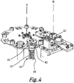
- the first die support 34 has first and second die supporting portions 40, 42 (as shown in Figure 3 ) which are spaced from one another.
- each die cartridge 44 includes a cartridge support 46 which is secured to a main body 48 of the carousel first die support 34.
- the cartridge 44 also includes a main body 48 which is secured to the cartridge support 46 and thereby forms part of the first die support 34.
- the die cartridges 44 are configured to support a plurality (for example 5 or 6) of dies.
- the first and second die supporting portions 40, 42 in the form of first and second cartridges may support dies of the same type.
- the first and second die supporting portions in the form of first and second die cartridges may support different types of die - that is to say, the first die supporting portion may support a plurality of dies of a first type, and the second die supporting portion may support a plurality of dies of a second type.
- first die supporting portion 40 and second die supporting portion 42 are not shown, at all or in their entirety, within some of the figures.
- Figure 2 shows cartridge support for both the first and second die supporting portions, 40, 42.
- Figure 4 shows the cartridge supporting portion 46 and main body 48 of the cartridge for the first die supporting portion 40, whereas only the cartridge support of the second die supporting portion is visible.
- Figure 5 shows only the first die supporting portion 40 in the form of the cartridge 44 including both the cartridge support 46 and cartridge main body 48.
- the figures only show two die supporting portions. It is within the scope of the present invention for there to be any number greater than one of die supporting portions.
- the carousel first die support 34 includes several additional spaces (for example those indicated by reference numeral 52) which could each serve as a location for a further die supporting portion.
- the design of the first die support shown in the figures should not be taken to be limiting - for example, the carousel first support portion may have any appropriate number greater than one number of locations on it for die supporting portions.
- die supporting portions shown within the figures of the present document are cartridges which hold a plurality of dies, any appropriate die supporting portion may be used. Such a die supporting portion may include one or more dies. In addition, in embodiments in which a plurality of dies are supported by each die supporting portion, the plurality of dies supported by each die supporting portion need not be the same.
- first and second die supporting portions 40, 42 are spaced from one another.
- first and second die supporting portions are angularly spaced from one another about the first axis A.
- the die support 34 is movable so that either the first die supporting portion 40 or second die supporting portion 42 are locatable at a first transfer position 54.
- the nature of the first transfer position 54 is discussed in more detail at a later point within this document.
- the die support 34 is rotatable in either direction in order to locate the first or second die supporting portion at the first transfer position 54.
- first die support 34 of the die changer 14 is rotatable in either direction is advantageous over any such system which is only movable/rotatable in a single direction because it ensures that when it is necessary to rotate the first die support so as to change the die supporting portion (or waste receptacle/conduit - see later) located at the first transfer position, the quickest direction of rotation (clockwise or anticlockwise) between the current die supporting portion located at the first transfer position and the die supporting portion it is intended to locate at the first transfer position can be used.
- the die changer 14 also includes a transfer arrangement 56.
- the transfer arrangement 56 takes the form of an arm 58 which is both translatable and rotatable about a second axis B.
- the transfer arrangement 56 and its actuator are mounted to a base plate 60 from which the arm 38 supporting the first die support 34 depends.
- the transfer arrangement 56 comprises a first grip portion indicated generally by reference numeral 62.
- the specifics of operation of the first grip portion (and second grip portion, described later) is not key to the present invention.
- Any appropriate arrangement may be used as a grip portion according to the present invention provided it is capable of being placed adjacent to or around a die and then actuated so as to exert a force on the die so as to secure it to the transfer arrangement and then, later, be de-actuated so as to release the die from the transfer arrangement.
- Suitable examples include a grip portion including a grip member which extends to contact the die or an electromagnet which can be actuated so as to magnetically retain the die.
- the first grip portion is configured to grip a die from one of the first and second die supporting portions when one of the first and second die supporting portions 40, 42 is located at the first transfer position 54, and thereby remove said gripped die from the first die support.
- the die supporting portion from which a die is to be extracted by the transfer arrangement is located at the first transfer position. This is achieved by moving the first die support 34, which, in the present case, is movement by rotation.
- the first transfer position is a position vertically below (with respect to the orientation of the apparatus shown in Figure 2 ) the first grip portion 62.
- the die supporting portion which is located at the first transfer position 54 is the second die supporting portion 42.
- the transfer arrangement 56 (and therefore arm 58 and first grip portion 60) are translated along axis B in the direction C by the actuator of the transfer arrangement 56.
- the transfer arrangement moves in the direction C until it contacts the second die supporting portion 42.
- contacting the second die supporting portion causes a die to be released from the second cartridge which constitutes the second die supporting portion 42. Further details regarding the operation of the cartridge are not of importance to the invention and, consequently, for the sake of brevity, are not discussed in any more detail here.
- the first grip portion 62 is then actuated so as to grip the die.
- the actuator of the transfer arrangement 56 then actuates the transfer arrangement 56 so as to move it along the axis B in the direction D away from the first die support 34. In this way the gripped die is removed from the second die supporting portion 42 and hence the first die support 34.
- the transfer arrangement 56 is movable, independently of the die support 34, between a first configuration (as shown in Figure 2 ) in which the first grip portion 62 can grip the relevant die from the relevant die supporting portion in the manner discussed above (i.e. by moving the transfer arrangement 56 in the direction C and the actuating the first grip portion 62), and a second configuration (as shown in Figure 3 ) in which the first grip portion can release said die and pass it to a second die support 28 of a rivet setter 12 located at a second transfer position 64.
- the movement of the transfer arrangement between the first configuration shown in Figure 2 and the second configuration shown in Figure 3 constitutes a rotation of the transfer arrangement 56 about axis B by 180 degrees.
- Such rotation is carried out by the transfer arrangement actuator.
- the rotation may occur in either a clockwise direction E or an anti-clockwise direction F, as is most appropriate.
- the rotation of the transfer arrangement 56 between the first configuration and the second configuration may be any appropriate amount of rotation, for example, but not limited to 30°, 45°, 60°, 90°, 120°, 135°, 150° and 180°.
- the amount of rotation of the transfer arrangement 56 from the first configuration to the second configuration and then from the second configuration to the first configuration may be 360°.
- the amount of rotation from the first configuration to the second configuration may be the same as the amount of rotation from the second configuration to the first configuration. In other embodiments this need not be the case.
- the transfer arrangement may have any appropriate shape or structure provided it is configured to rotate between the first configuration and the second configuration.
- the second transfer position is best understood with reference to Figure 6.
- Figure 6 shows a portion of the rivet setter 12 and a portion of the die changer 14.
- the die support 28 of the rivet setter 12 supports a die 30.
- Die 30 may be removed in any appropriate manner. A specific manner according to the present invention is discussed at a later point within the present document. For the sake of discussing the second configuration of the transfer arrangement 56 in which the first grip portion 62 can release a die and pass it to the second die support 28 of a rivet setter located at a second transfer position, we should assume that the die 30 within Figure 6 has already been removed.
- the second transfer position at which the second die support 28 of the rivet setter 12 is located is the position of the die support 28 when the rivet setter 12 is moved relative to the die changer 14 such that a shoulder 66 of the rivet setter 12 abuts a hard stop of the die changer 14 in the form of surface 68.
- the die support 28 is located vertically below (given the orientation of the Figures) the first grip portion 62 when the transfer arrangement 56 is in the second configuration (as shown in Figure 3 ).
- the actuator of the transfer arrangement 56 actuates the transfer arrangement 56 so as to move it along axis B in the direction C.
- the gripped die is thereby located in the second die support 28 and the first grip portion 62 can be de-actuated so that it releases the die and leaves it in the second die support 28.
- a die retention mechanism within the second die support can be actuated to retain the die within the second die support.
- the actuator of the transfer arrangement 56 can be actuated so as to move the transfer arrangement 56 along the axis B in the direction D so as to return the transfer arrangement 56 to its original position.
- the transfer arrangement 56 comprises a second grip portion 70 located at the opposite end of the arm 58 of the transfer arrangement 56 as compared to the first grip portion 62.
- the first and second grip portions are substantially identical and operate in a substantially identical manner.
- the second grip portion 70 can grip a second die 30 from the second die support 28 of the rivet setter 12 when the rivet setter is located at the second transfer position. This is achieved as follows: when the transfer arrangement 56 is in the first configuration the actuator of the transfer arrangement 56 can actuate the transfer arrangement 56 so as to move it along the axis B in the direction C such that the second grip portion 70 is located adjacent to or around the second die 30.
- the second grip portion can then be actuated so as to cause it to exert a force on the second die and thereby secure the second die to the second grip portion.
- the transfer arrangement 56 can then be actuated by the actuator of the transfer arrangement so as to move the transfer arrangement along the axis B in the direction D. This removes the second die 30 from the second die support 28.
- the second die 30 Before the second die 30 is to be removed, whilst the rivet setter is operating to insert rivets into a workpiece, the second die 30 is secured to the second die support 28.
- a die retention mechanism that is of a known type. Due to the fact that the die retention mechanism is known and its operation is not key to the carrying out of the invention, for the sake of brevity, its operation is not discussed in any further detail. That said, given that the second die 30 is normally secured to the second die support, it will be clear that before the second die 30 is removed from the second die support 28 the die retention mechanism has to be released. In the present embodiment this is achieved as follows.
- Figure 6 shows a die removal pin 72. The die removal pin 72 is located beneath the second transfer position.
- the die removal pin 72 When the rivet setter is located at the second transfer position, the die removal pin 72 is moved vertically upwards through an aperture (not shown) in the underside of the C-frame. The die removal pin 72 passes through the aperture into the second die support 28, where it causes the die retention mechanism to release and the die to move slightly upwards. Once the die retention mechanism has been released and the die has moved upwards the die can be gripped by the second grip portion 70 and removed from the second die support.
- this portion of operation of the transfer arrangement can occur simultaneously to when the first grip portion grips a die from the first or second die supporting portion, as discussed above. Consequently, provided that the first or second die supporting portion is located at the first transfer position, and the second die support of the rivet setter is located at the second transfer position simultaneously, then the first grip portion 62 of the transfer arrangement 56 can grip the die to be removed from the first or second die supporting portion at the same time that the second grip portion 70 can grip the die 30 to be removed from the second die support 28.
- the transfer arrangement 56 can be moved to the second configuration.
- the second grip portion 70 is de-actuated so as to release the second die 30 and pass it to a disposal target.
- the disposal target may be located at the first transfer position.
- this portion of operation of the transfer arrangement can occur simultaneously to when the first grip portion 62 releases the die and passes it to the second die support 28 of the rivet setter 12 located at a second transfer position 64, as discussed above. Consequently, provided that the disposal target is located at the first transfer position, and the second die support of the rivet setter is located at the second transfer position simultaneously, the first grip portion 62 can release the die and pass it to the second die support 28 of the rivet setter 12 at the same time that the second grip portion 70 can release the die 30 and pass it to the disposal target.
- the disposal target may be any appropriate entity to which it is desired to pass used dies.
- the disposal target may be separate to the first die support.
- the disposal target forms part of the first die support 34 and the disposal target is a waste conduit 74.
- the waste conduit 74 is secured to the first die support 34 in one of the additional spaces 52 of the carousel.
- the waste conduit 74 extends generally vertically downwards and is sized so that a die can pass through it.
- the waste conduit has a first end 74a connected to the first die support 34 and a second end 74b spaced from the first end 74a.
- the first die support 34 is located such that when the first end 74a of the waste conduit 74 is located at the first transfer position 54, the second end 74b of the waste conduit 74 is located adjacent a second waste conduit 76, as seen best in Figure 2 , such that if the second die is passed to the waste conduit 74, the second die will pass (via the action of gravity) through the waste conduit 74 from the first end 74a to the second end 74b, and then into the second waste conduit 76.
- the second waste conduit may be replaced with or additionally include a second waste receptacle.
- the first end of the waste conduit is located at the first transfer position, the second end of the waste conduit is located adjacent the second waste receptacle such that if the second die is passed to the waste conduit, the second die will pass (via the action of gravity) through the waste conduit from the first end to the second end, and then into the second waste receptacle.
- the first waste conduit is connected to the first die support such that it moves therewith, whereas the second waste conduit or second waste receptacle is separate to the first die support such that it does not move with the first die support.
- the first waste conduit 74 may be replaced by a waste receptacle.
- a waste conduit is designed to carry waste (e.g. waste dies) from one location to another, whereas a waste receptacle is designed to store or contain the waste, before the waste is emptied as part of a maintenance operation.
- the disposal targets discussed have been those where it is desired to treat the die removed from the rivet setter as waste. This may be the case if the die has carried out so many riveting operations such that it is worn out. In other applications the die removed from the rivet setter may not be fully worn and may therefore not be waste. In such instances it may be desirable for the die to be placed in a die supporting portion so that it can be reused at a later point. To that end the disposal target may be one of: the first die supporting portion, the second die supporting portion or a third die supporting portion.
- the fastening apparatus is located in a restricted area, to which access by personnel is restricted for safety reasons. In such situations it is common that all the machinery within the restricted area must be powered down before personnel can enter.
- the rivet setter may be located on the end of a robotic arm. Because the rivet setter is located at the end of a robotic arm, the rivet setter presents a safety risk - the robotic arm may inadvertently move the rivet setter, thereby causing injury. For this reason, in this instance, the rivet setter is located in a restricted area. Due to the fact that the rivet setter must access the die changer, at least a portion of the die changer must also be located in the restricted area.
- the first transfer position 54 is located in the restricted area R and the second waste conduit 76 comprises third 76a and fourth 76b spaced ends, the third end 76a being located adjacent the waste conduit 74 when the second end 74b of the waste conduit 74 is located adjacent the second waste conduit 76, and the fourth end 76b is located outside of the restricted area (also referred to the unrestricted area U).
- the first and second waste conduits can convey any die removed from the rivet setter to a location outside of the restricted area. In this way it is not necessary for an operator to enter the restricted area in order to remove waste dies. As such, removing waste dies does not result in downtime for the fastening apparatus.
- the first transfer position 54 is located in the restricted area R; and a portion of the first die support 34 is locatable outside the restricted area (in unrestricted area U), said portion of the first die support comprising the disposal target or the waste receptacle.
- a portion of the first die support 34 is locatable outside the restricted area (in unrestricted area U), said portion of the first die support comprising the disposal target or the waste receptacle.
- the first transfer position 54 is located in the restricted area R.
- a portion of the first die support 34 is locatable outside the restricted area (in the unrestricted area U), said portion of the first die support comprising the first and/or second die supporting portion 40, 42.
- the first and/or second die supporting portion outside the restricted area.
- Being able to move the first and/or second die supporting portions so that they are outside of the restricted area means that any die support portion which runs out of relevant dies can be replenished without the need to access the restricted area and therefore the need to shut down the machinery in the restricted area.
- the first waste receptacle or second waste receptacle may support said plurality of received dies next to one another in the same order to that in which the dies are received.
- Figure 7 shows a second waste receptacle 78 located at the end of first and second waste conduits 74, 76.
- the diameter of the second waste receptacle 78 is only slightly greater than the diameter of the dies received by the second waste receptacle. In this way the second waste receptacle 78 supports said plurality of received dies next to one another in the same order to that in which the dies are received. That is to say die 30a was received first die 30b, which is next to die 30a, was received second; and the space 30c next to die 30b will be occupied by die 30 once it is released.
- the waste receptacle 78 may be beneficial for the waste receptacle 78 to support the received dies in the order they are received, because this enables post-analysis of the dies based on the chronology of when each die was removed from the rivet setter.
- the manner in which the second waste receptacle 78 supports said plurality of received dies next to one another in the same order to that in which the dies are received is due to the diameter of the second waste receptacle 78 being only slightly greater than the diameter of the dies received by the second waste receptacle.
- any appropriate arrangement which supports said plurality of received dies next to one another in the same order to that in which the dies are received may be used.
- the first die support is a carousel
- the first and second die supporting portions are angularly spaced and the movement of the first die support is rotation about an axis. In other embodiments this need not be the case - the first die support may have any appropriate shape - for example, linear or rectangular. In these examples the first and second die supporting portions are not angularly spaced and the movement of the first die support will be a translation.
Landscapes
- Engineering & Computer Science (AREA)
- Mechanical Engineering (AREA)
- Mounting, Exchange, And Manufacturing Of Dies (AREA)
Claims (16)
- Matrizenwechselvorrichtung, die Folgendes umfasst:eine erste Matrizenstütze (34) zum Stützen einer Vielzahl von Matrizen, wobei die erste Matrizenstütze einen ersten und einen zweiten Matrizenstützabschnitt (40, 42), die voneinander beabstandet sind, aufweist, wobei die Matrizenstütze so beweglich ist, dass entweder der erste Matrizenstützabschnitt oder der zweite Matrizenstützabschnitt bei einer ersten Übergabestellung (54) positioniert werden kann,eine Übergabeanordnung (56), die einen ersten Greifabschnitt (62) umfasst, der dafür konfiguriert ist, eine Matrize von einem von dem ersten und dem zweiten Matrizenstützabschnitt zu greifen, wenn der eine von dem ersten und dem zweiten Matrizenstützabschnitt bei der ersten Übergabestellung positioniert ist, und dadurch die gegriffene Matrize von der ersten Matrizenstütze zu entfernen,wobei die Übergabeanordnung, unabhängig von der ersten Matrizenstütze, beweglich ist zwischen einer ersten Konfiguration, in welcher der erste Greifabschnitt dafür konfiguriert ist, die Matrize von dem einen von dem ersten und dem zweiten Matrizenstützabschnitt zu greifen, wenn der eine von dem ersten und dem zweiten Matrizenstützabschnitt bei der ersten Übergabestellung positioniert ist, und einer zweiten Konfiguration, in welcher der erste Greifabschnitt dafür konfiguriert ist, die Matrize freizugeben und sie zu einer zweiten Matrizenstütze (28) eines Nietenziehers (12), der bei einer zweiten Übergabestellung (64) positioniert ist, weiterzuleiten,wobei die Matrizenwechselvorrichtung dadurch gekennzeichnet ist, dassdie Übergabeanordnung einen zweiten Greifabschnitt (70) umfasst, und wobei in der ersten Konfiguration der Übergabeanordnung der zweite Greifabschnitt dafür konfiguriert ist, eine zweite Matrize (30) von der zweiten Matrizenstütze des Nietenziehers, der bei der zweiten Übergabestellung positioniert ist, zu greifen, und in der zweiten Konfiguration der Übergabeanordnung der zweite Greifabschnitt dafür konfiguriert ist, die zweite Matrize freizugeben und sie zu einem Entsorgungsziel weiterzuleiten.
- Matrizenwechselvorrichtung nach Anspruch 1, wobei die Bewegung der Übergabeanordnung (56) zwischen der ersten Konfiguration und der zweiten Konfiguration eine Drehung um eine Achse (B) ist.
- Matrizenwechselvorrichtung nach Anspruch 1 oder Anspruch 2, wobei die erste Matrizenstütze (34) ein Karussell ist, das um eine erste Achse (A) drehbar ist, wobei der erste und der zweite Matrizenstützabschnitt (40, 42) um die erste Achse winklig voneinander beabstandet sind, wobei die erste Matrizenstütze so drehbar ist, dass entweder der erste Matrizenstützabschnitt oder der zweite Matrizenstützabschnitt bei der ersten Übergabestellung (54) positioniert werden kann.
- Matrizenwechselvorrichtung nach einem der vorhergehenden Ansprüche, wobei das Entsorgungsziel einen Teil der ersten Matrizenstütze (34) bildet.
- Matrizenwechselvorrichtung nach Anspruch 4, wobei das Entsorgungsziel eines von Folgendem ist: der erste Matrizenstützabschnitt (40), der zweite Matrizenstützabschnitt (42) oder ein dritter Matrizenstützabschnitt.
- Matrizenwechselvorrichtung nach Anspruch 4, wobei das Entsorgungsziel der ersten Matrizenstütze (34) ein Abfallbehälter (78) oder -kanal (74, 76) ist.
- Matrizenwechselvorrichtung nach einem der Ansprüche 1 bis 3, wobei die erste Matrizenstütze (34) einen Abfallbehälter oder -kanal (74) umfasst und wobei die Übergabeanordnung (56) dafür konfiguriert ist, eine zweite Matrize (30) von der zweiten Matrizenstütze (28) eines Nietenziehers (12) zu entfernen und sie zu dem Abfallbehälter oder -kanal weiterzuleiten, wenn der Abfallbehälter oder -kanal bei der ersten Übergabestellung (54) positioniert ist.
- Matrizenwechselvorrichtung nach Anspruch 6 oder Anspruch 7, wobei die erste Matrizenstütze (34) einen Abfallkanal (74) umfasst, wobei der Abfallkanal ein erstes Ende (74a), das mit der ersten Matrizenstütze verbunden ist, und ein zweites Ende (74b), das von dem ersten Ende beabstandet ist, aufweist, wobei die Matrizenwechselvorrichtung dafür konfiguriert ist, dass dadurch, wenn die erste Matrizenstütze derart positioniert ist, dass der Abfallkanal bei der ersten Übergabestellung (54) positioniert ist, das zweite Ende des Abfallkanals angrenzend an einen zweiten Abfallbehälter oder -kanal (76) positioniert ist, so dass, falls die zweite Matrize zu dem Abfallkanal weitergeleitet wird, die zweite Matrize von dem ersten Ende bis zu dem zweiten Ende durch den Abfallkanal hindurch und danach in den zweiten Abfallbehälter oder -kanal gehen kann.
- Verfahren zum Wechseln einer Matrize unter Verwendung einer Matrizenwechselvorrichtung (14), wobei die Matrizenwechselvorrichtung Folgendes umfasst:
eine erste Matrizenstütze (34), wobei die erste Matrizenstütze einen ersten und einen zweiten Matrizenstützabschnitt (40, 42), die voneinander beabstandet sind, und eine Übergabeanordnung (56), die einen ersten Greifabschnitt (62) umfasst, aufweist, wobei das Verfahren Folgendes umfasst:Stützen einer Vielzahl von Matrizen (30) auf der ersten Matrizenstütze,Bewegen der ersten Matrizenstütze so, dass entweder der erste Matrizenstützabschnitt oder der zweite Matrizenstützabschnitt bei einer ersten Übergabestellung (54) positioniert wird,wobei der erste Greifabschnitt eine Matrize von einem von dem ersten und dem zweiten Matrizenstützabschnitt greift, wenn der eine von dem ersten und dem zweiten Matrizenstützabschnitt bei der ersten Übergabestellung positioniert ist, und die Übergabeanordnung dadurch die gegriffene Matrize von der ersten Matrizenstütze entfernt,Bewegen der Übergabeanordnung, unabhängig von der ersten Matrizenstütze, zwischen einer ersten Konfiguration, in der das Greifen erfolgen kann, und einer zweiten Konfiguration, in welcher der erste Greifabschnitt die Matrize freigibt und sie zu einer zweiten Matrizenstütze (28) eines Nietenziehers (12), der bei einer zweiten Übergabestellung (64) positioniert ist, weiterleitet,wobei das Verfahren zum Wechseln einer Matrize dadurch gekennzeichnet ist, dassdie Übergabeanordnung einen zweiten Greifabschnitt (70) umfasst, und wobei in der ersten Konfiguration der Übergabeanordnung der zweite Greifabschnitt eine zweite Matrize (30) von der zweiten Matrizenstütze eines Nietenziehers, der bei der zweiten Übergabestellung positioniert ist, greift und in der zweiten Konfiguration der Übergabeanordnung der zweite Greifabschnitt die zweite Matrize freigibt und sie zu einem Entsorgungsziel weiterleitet. - Verfahren nach Anspruch 9, wobei die erste Matrizenstütze (34) ein Karrussell ist, das um eine erste Achse (A) drehbar ist, wobei der erste und der zweite Matrizenstützabschnitt (40, 42) um die erste Achse winklig voneinander beabstandet sind, wobei das Bewegen der ersten Matrizenstütze so, dass entweder der erste Matrizenstützabschnitt oder der zweite Matrizenstützabschnitt bei einer ersten Übergabestellung (54) positioniert wird, umfasst, dass die erste Matrizenstütze so gedreht wird, dass sich entweder der erste Matrizenstützabschnitt oder der zweite Matrizenstützabschnitt bei der ersten Übergabestellung (54) befindet.
- Verfahren nach Anspruch 9 oder Anspruch 10, wobei das Entsorgungsziel einen Teil der ersten Matrizenstütze (34) bildet.
- Verfahren nach Anspruch 11, wobei das Entsorgungsziel eines von Folgendem ist: der erste Matrizenstützabschnitt (40), der zweite Matrizenstützabschnitt (42) oder ein dritter Matrizenstützabschnitt.
- Verfahren nach Anspruch 11, wobei das Entsorgungsziel der ersten Matrizenstütze (34) ein Abfallbehälter (78) oder -kanal (74, 76) ist.
- Verfahren nach Anspruch 9 oder 10, wobei die erste Matrizenstütze (34) einen Abfallbehälter oder -kanal (74) umfasst und wobei das Verfahren ferner Folgendes umfasst:
die Übergabeanordnung (56) entfernt eine zweite Matrize (30) von der zweiten Matrizenstütze (28) eines Nietenziehers (12) und leitet sie zu dem Abfallbehälter oder -kanal weiter, wenn der Abfallbehälter oder -kanal bei der ersten Übergabestellung (54) positioniert ist. - Verfahren nach Anspruch 13 oder Anspruch 14, wobei die erste Matrizenstütze (34) einen Abfallkanal (74) umfasst, wobei der Abfallkanal ein erstes Ende (74a), das mit der ersten Matrizenstütze verbunden ist, und ein zweites Ende (74b), das von dem ersten Ende beabstandet ist, aufweist, wobei das Verfahren ferner Folgendes umfasst:Positionieren der ersten Matrizenstütze derart, dass der Abfallkanal bei der ersten Übergabestellung (54) positioniert ist,Positionieren des zweiten Endes des Abfallkanals angrenzend an einen zweiten Abfallbehälter oder -kanal (76),Weiterleiten der zweiten Matrize (30) zu dem Abfallkanal, so dass die zweite Matrize von dem ersten Ende bis zu dem zweiten Ende durch den Abfallkanal hindurch und danach in den zweiten Abfallbehälter oder -kanal geht.
- Verfahren nach einem der Ansprüche 9 bis 15 oder Matrizenwechselvorrichtung nach einem der Ansprüche 1 bis 8, wobei sowohl der erste Matrizenstützabschnitt (40) als auch der zweite Matrizenstützabschnitt (42) dafür konfiguriert ist, eine Vielzahl von Matrizen (30) zu stützen, wobei der erste Matrizenstützabschnitt dafür konfiguriert ist, eine Vielzahl von Matrizen einer ersten Art zu stützen, und der zweite Matrizenstützabschnitt dafür konfiguriert ist, eine Vielzahl von Matrizen einer zweiten Art zu stützen.
Applications Claiming Priority (2)
| Application Number | Priority Date | Filing Date | Title |
|---|---|---|---|
| GB1709622.3A GB2563441B (en) | 2017-06-16 | 2017-06-16 | Die changing apparatus |
| PCT/GB2018/051652 WO2018229502A1 (en) | 2017-06-16 | 2018-06-15 | Die changing apparatus |
Publications (2)
| Publication Number | Publication Date |
|---|---|
| EP3638434A1 EP3638434A1 (de) | 2020-04-22 |
| EP3638434B1 true EP3638434B1 (de) | 2022-07-06 |
Family
ID=59462584
Family Applications (1)
| Application Number | Title | Priority Date | Filing Date |
|---|---|---|---|
| EP18734903.0A Active EP3638434B1 (de) | 2017-06-16 | 2018-06-15 | Matrizenwechsel-vorrichtung und -verfahren |
Country Status (7)
| Country | Link |
|---|---|
| US (1) | US11524329B2 (de) |
| EP (1) | EP3638434B1 (de) |
| JP (1) | JP7047081B2 (de) |
| KR (1) | KR102354186B1 (de) |
| CN (1) | CN111032246A (de) |
| GB (1) | GB2563441B (de) |
| WO (1) | WO2018229502A1 (de) |
Families Citing this family (4)
| Publication number | Priority date | Publication date | Assignee | Title |
|---|---|---|---|---|
| DE102020134085A1 (de) | 2020-12-18 | 2022-06-23 | Audi Aktiengesellschaft | Matrizenwechsler für stationäre Stanznietsysteme |
| CN112775384B (zh) * | 2021-02-04 | 2023-03-14 | 深圳市锐特尔精密模具有限公司 | 一种用于压铆机的多工位下模换模装置 |
| CN114453550B (zh) * | 2021-11-15 | 2023-11-14 | 安阳锻压数控设备有限公司 | 汽车车架自动铆接铆模更换装置 |
| EP4656309A1 (de) * | 2024-05-27 | 2025-12-03 | Nemak, S.A.B. de C.V. | Matrizenwechselsystem und verfahren zum wechseln einer matrize |
Family Cites Families (13)
| Publication number | Priority date | Publication date | Assignee | Title |
|---|---|---|---|---|
| FR891986A (fr) * | 1942-03-26 | 1944-03-24 | Arado Flugzeugwerke Gmbh | Machine à river comprenant plusieurs porte-outils inférieurs |
| US6910263B2 (en) | 2001-12-25 | 2005-06-28 | Newfrey Llc | Self-piercing rivet setting apparatus and system |
| JP2004001045A (ja) | 2002-05-31 | 2004-01-08 | Nippon Pop Rivets & Fasteners Ltd | 自動穿孔リベット締結装置 |
| US7032296B2 (en) * | 2003-11-21 | 2006-04-25 | Newfrey Llc | Self-piercing fastening system |
| CN201331574Y (zh) * | 2008-12-29 | 2009-10-21 | 北京中科三环高技术股份有限公司 | 一种自动检测磁通装置 |
| US9162277B2 (en) | 2013-02-18 | 2015-10-20 | Ford Motor Company | Indexing self-piercing die riveter |
| DE202013011928U1 (de) | 2013-12-18 | 2014-10-30 | Newfrey Llc | Wechselmatrize und Fügewerkzeug |
| DE202013011927U1 (de) * | 2013-12-18 | 2014-10-30 | Newfrey Llc | Wechselmatrizen-Übergabestation und Fügewerkzeugsystem |
| CN203875018U (zh) * | 2014-06-18 | 2014-10-15 | 四川蓝彩电子科技有限公司 | 玻璃封装二极管次品剔除和合格品输送装置 |
| DE102015107337A1 (de) * | 2015-05-11 | 2016-11-17 | Böllhoff Verbindungstechnik GmbH | Matrizenwechsler mit daran angepasster Wechselmatrize und Matrizendom sowie Verfahren zum Entfernen und Einsetzen der Wechselmatrize |
| CN104858282B (zh) * | 2015-06-02 | 2017-03-15 | 安徽飞翔电器有限公司 | 具有自动旋转接送料功能的冲压机床 |
| CN106334667B (zh) | 2016-09-27 | 2018-08-24 | 大连海洋大学 | 一种用于枝角类活体分级的装置及分级方法 |
| CN106334677B (zh) * | 2016-11-03 | 2019-03-15 | 成都瑞拓科技股份有限公司 | 胶囊质量快速检测系统 |
-
2017
- 2017-06-16 GB GB1709622.3A patent/GB2563441B/en active Active
-
2018
- 2018-06-15 WO PCT/GB2018/051652 patent/WO2018229502A1/en not_active Ceased
- 2018-06-15 CN CN201880051713.7A patent/CN111032246A/zh active Pending
- 2018-06-15 JP JP2020519186A patent/JP7047081B2/ja active Active
- 2018-06-15 EP EP18734903.0A patent/EP3638434B1/de active Active
- 2018-06-15 US US16/623,161 patent/US11524329B2/en active Active
- 2018-06-15 KR KR1020207001520A patent/KR102354186B1/ko active Active
Also Published As
| Publication number | Publication date |
|---|---|
| US20210053103A1 (en) | 2021-02-25 |
| KR102354186B1 (ko) | 2022-01-24 |
| EP3638434A1 (de) | 2020-04-22 |
| JP2020523203A (ja) | 2020-08-06 |
| KR20200038929A (ko) | 2020-04-14 |
| GB2563441A (en) | 2018-12-19 |
| GB2563441B (en) | 2022-03-23 |
| GB201709622D0 (en) | 2017-08-02 |
| CN111032246A (zh) | 2020-04-17 |
| WO2018229502A1 (en) | 2018-12-20 |
| JP7047081B2 (ja) | 2022-04-04 |
| US11524329B2 (en) | 2022-12-13 |
Similar Documents
| Publication | Publication Date | Title |
|---|---|---|
| US11524329B2 (en) | Die changing apparatus | |
| CA2975287C (en) | Punch assembly with replaceable punch tip | |
| EP2437913B1 (de) | Vereinzelungsführung für eine zufuhrvorrichtung für ein verbindungselement | |
| EP0813463B1 (de) | Verfahren und maschine zum anbringen von einsätzen | |
| US4162641A (en) | Automatic loading and unloading for numerically controlled turret punch | |
| DE69001202T2 (de) | Werkzeuganlage zum nieten von werkstuecken. | |
| US20060053857A1 (en) | Tool system for bending sheet materials and method of using same | |
| US20090279991A1 (en) | Processing tool and method for transferring a component from a ready position into a processing position | |
| US11253959B2 (en) | Method and device for furnishing screws | |
| JP2016215218A (ja) | 上型ホルダ、プレス機械、及び上型保持方法 | |
| CN113795340A (zh) | 金属板折弯机 | |
| US12214412B2 (en) | Apparatus for clinch joining | |
| WO2013040588A2 (en) | Rotary actuated axial clamp | |
| WO1995000267A1 (en) | Punching press and die mounting method | |
| EP3072630B1 (de) | Zelle für das Einsetzen von Bauelementen in Werkstücke | |
| EP3638433B1 (de) | Befestigungsvorrictung umfassend eine matrizenpatrone und ein matrizenwechsler und verfahren zur befestigung mindestens zweier materialblechen | |
| US3827278A (en) | Joggling tool | |
| US6178799B1 (en) | Forming press and method for shaping angle-section workpieces | |
| CN104607986A (zh) | 一种周转料盒定位机构 | |
| US20230173604A1 (en) | Automated fastener feeder and securing system | |
| EP4656309A1 (de) | Matrizenwechselsystem und verfahren zum wechseln einer matrize | |
| Zhang et al. | Design and experimental simulation analysis of automatic recycling and processing device for neutral refills | |
| DE102020134085A1 (de) | Matrizenwechsler für stationäre Stanznietsysteme |
Legal Events
| Date | Code | Title | Description |
|---|---|---|---|
| STAA | Information on the status of an ep patent application or granted ep patent |
Free format text: STATUS: UNKNOWN |
|
| STAA | Information on the status of an ep patent application or granted ep patent |
Free format text: STATUS: THE INTERNATIONAL PUBLICATION HAS BEEN MADE |
|
| PUAI | Public reference made under article 153(3) epc to a published international application that has entered the european phase |
Free format text: ORIGINAL CODE: 0009012 |
|
| STAA | Information on the status of an ep patent application or granted ep patent |
Free format text: STATUS: REQUEST FOR EXAMINATION WAS MADE |
|
| 17P | Request for examination filed |
Effective date: 20200115 |
|
| AK | Designated contracting states |
Kind code of ref document: A1 Designated state(s): AL AT BE BG CH CY CZ DE DK EE ES FI FR GB GR HR HU IE IS IT LI LT LU LV MC MK MT NL NO PL PT RO RS SE SI SK SM TR |
|
| AX | Request for extension of the european patent |
Extension state: BA ME |
|
| DAV | Request for validation of the european patent (deleted) | ||
| DAX | Request for extension of the european patent (deleted) | ||
| RAP1 | Party data changed (applicant data changed or rights of an application transferred) |
Owner name: ATLAS COPCO IAS UK LIMITED |
|
| STAA | Information on the status of an ep patent application or granted ep patent |
Free format text: STATUS: EXAMINATION IS IN PROGRESS |
|
| 17Q | First examination report despatched |
Effective date: 20210310 |
|
| RAP3 | Party data changed (applicant data changed or rights of an application transferred) |
Owner name: ATLAS COPCO IAS UK LIMITED |
|
| GRAP | Despatch of communication of intention to grant a patent |
Free format text: ORIGINAL CODE: EPIDOSNIGR1 |
|
| STAA | Information on the status of an ep patent application or granted ep patent |
Free format text: STATUS: GRANT OF PATENT IS INTENDED |
|
| INTG | Intention to grant announced |
Effective date: 20220224 |
|
| GRAS | Grant fee paid |
Free format text: ORIGINAL CODE: EPIDOSNIGR3 |
|
| GRAA | (expected) grant |
Free format text: ORIGINAL CODE: 0009210 |
|
| STAA | Information on the status of an ep patent application or granted ep patent |
Free format text: STATUS: THE PATENT HAS BEEN GRANTED |
|
| RBV | Designated contracting states (corrected) |
Designated state(s): AL AT BE BG CH CY CZ DE DK EE ES FI FR GR HR HU IE IS IT LI LT LU LV MC MK MT NL NO PL PT RO RS SE SI SK SM TR |
|
| AK | Designated contracting states |
Kind code of ref document: B1 Designated state(s): AL AT BE BG CH CY CZ DE DK EE ES FI FR GR HR HU IE IS IT LI LT LU LV MC MK MT NL NO PL PT RO RS SE SI SK SM TR |
|
| REG | Reference to a national code |
Ref country code: AT Ref legal event code: REF Ref document number: 1502498 Country of ref document: AT Kind code of ref document: T Effective date: 20220715 Ref country code: CH Ref legal event code: EP |
|
| REG | Reference to a national code |
Ref country code: DE Ref legal event code: R096 Ref document number: 602018037587 Country of ref document: DE |
|
| REG | Reference to a national code |
Ref country code: IE Ref legal event code: FG4D |
|
| REG | Reference to a national code |
Ref country code: LT Ref legal event code: MG9D |
|
| REG | Reference to a national code |
Ref country code: NL Ref legal event code: MP Effective date: 20220706 |
|
| PG25 | Lapsed in a contracting state [announced via postgrant information from national office to epo] |
Ref country code: SE Free format text: LAPSE BECAUSE OF FAILURE TO SUBMIT A TRANSLATION OF THE DESCRIPTION OR TO PAY THE FEE WITHIN THE PRESCRIBED TIME-LIMIT Effective date: 20220706 Ref country code: RS Free format text: LAPSE BECAUSE OF FAILURE TO SUBMIT A TRANSLATION OF THE DESCRIPTION OR TO PAY THE FEE WITHIN THE PRESCRIBED TIME-LIMIT Effective date: 20220706 Ref country code: PT Free format text: LAPSE BECAUSE OF FAILURE TO SUBMIT A TRANSLATION OF THE DESCRIPTION OR TO PAY THE FEE WITHIN THE PRESCRIBED TIME-LIMIT Effective date: 20221107 Ref country code: NO Free format text: LAPSE BECAUSE OF FAILURE TO SUBMIT A TRANSLATION OF THE DESCRIPTION OR TO PAY THE FEE WITHIN THE PRESCRIBED TIME-LIMIT Effective date: 20221006 Ref country code: NL Free format text: LAPSE BECAUSE OF FAILURE TO SUBMIT A TRANSLATION OF THE DESCRIPTION OR TO PAY THE FEE WITHIN THE PRESCRIBED TIME-LIMIT Effective date: 20220706 Ref country code: LV Free format text: LAPSE BECAUSE OF FAILURE TO SUBMIT A TRANSLATION OF THE DESCRIPTION OR TO PAY THE FEE WITHIN THE PRESCRIBED TIME-LIMIT Effective date: 20220706 Ref country code: LT Free format text: LAPSE BECAUSE OF FAILURE TO SUBMIT A TRANSLATION OF THE DESCRIPTION OR TO PAY THE FEE WITHIN THE PRESCRIBED TIME-LIMIT Effective date: 20220706 Ref country code: FI Free format text: LAPSE BECAUSE OF FAILURE TO SUBMIT A TRANSLATION OF THE DESCRIPTION OR TO PAY THE FEE WITHIN THE PRESCRIBED TIME-LIMIT Effective date: 20220706 Ref country code: ES Free format text: LAPSE BECAUSE OF FAILURE TO SUBMIT A TRANSLATION OF THE DESCRIPTION OR TO PAY THE FEE WITHIN THE PRESCRIBED TIME-LIMIT Effective date: 20220706 |
|
| REG | Reference to a national code |
Ref country code: AT Ref legal event code: MK05 Ref document number: 1502498 Country of ref document: AT Kind code of ref document: T Effective date: 20220706 |
|
| PG25 | Lapsed in a contracting state [announced via postgrant information from national office to epo] |
Ref country code: PL Free format text: LAPSE BECAUSE OF FAILURE TO SUBMIT A TRANSLATION OF THE DESCRIPTION OR TO PAY THE FEE WITHIN THE PRESCRIBED TIME-LIMIT Effective date: 20220706 Ref country code: IS Free format text: LAPSE BECAUSE OF FAILURE TO SUBMIT A TRANSLATION OF THE DESCRIPTION OR TO PAY THE FEE WITHIN THE PRESCRIBED TIME-LIMIT Effective date: 20221106 Ref country code: HR Free format text: LAPSE BECAUSE OF FAILURE TO SUBMIT A TRANSLATION OF THE DESCRIPTION OR TO PAY THE FEE WITHIN THE PRESCRIBED TIME-LIMIT Effective date: 20220706 Ref country code: GR Free format text: LAPSE BECAUSE OF FAILURE TO SUBMIT A TRANSLATION OF THE DESCRIPTION OR TO PAY THE FEE WITHIN THE PRESCRIBED TIME-LIMIT Effective date: 20221007 |
|
| REG | Reference to a national code |
Ref country code: DE Ref legal event code: R097 Ref document number: 602018037587 Country of ref document: DE |
|
| PG25 | Lapsed in a contracting state [announced via postgrant information from national office to epo] |
Ref country code: SM Free format text: LAPSE BECAUSE OF FAILURE TO SUBMIT A TRANSLATION OF THE DESCRIPTION OR TO PAY THE FEE WITHIN THE PRESCRIBED TIME-LIMIT Effective date: 20220706 Ref country code: RO Free format text: LAPSE BECAUSE OF FAILURE TO SUBMIT A TRANSLATION OF THE DESCRIPTION OR TO PAY THE FEE WITHIN THE PRESCRIBED TIME-LIMIT Effective date: 20220706 Ref country code: DK Free format text: LAPSE BECAUSE OF FAILURE TO SUBMIT A TRANSLATION OF THE DESCRIPTION OR TO PAY THE FEE WITHIN THE PRESCRIBED TIME-LIMIT Effective date: 20220706 Ref country code: CZ Free format text: LAPSE BECAUSE OF FAILURE TO SUBMIT A TRANSLATION OF THE DESCRIPTION OR TO PAY THE FEE WITHIN THE PRESCRIBED TIME-LIMIT Effective date: 20220706 Ref country code: AT Free format text: LAPSE BECAUSE OF FAILURE TO SUBMIT A TRANSLATION OF THE DESCRIPTION OR TO PAY THE FEE WITHIN THE PRESCRIBED TIME-LIMIT Effective date: 20220706 |
|
| PLBE | No opposition filed within time limit |
Free format text: ORIGINAL CODE: 0009261 |
|
| STAA | Information on the status of an ep patent application or granted ep patent |
Free format text: STATUS: NO OPPOSITION FILED WITHIN TIME LIMIT |
|
| PG25 | Lapsed in a contracting state [announced via postgrant information from national office to epo] |
Ref country code: SK Free format text: LAPSE BECAUSE OF FAILURE TO SUBMIT A TRANSLATION OF THE DESCRIPTION OR TO PAY THE FEE WITHIN THE PRESCRIBED TIME-LIMIT Effective date: 20220706 Ref country code: EE Free format text: LAPSE BECAUSE OF FAILURE TO SUBMIT A TRANSLATION OF THE DESCRIPTION OR TO PAY THE FEE WITHIN THE PRESCRIBED TIME-LIMIT Effective date: 20220706 |
|
| 26N | No opposition filed |
Effective date: 20230411 |
|
| PG25 | Lapsed in a contracting state [announced via postgrant information from national office to epo] |
Ref country code: AL Free format text: LAPSE BECAUSE OF FAILURE TO SUBMIT A TRANSLATION OF THE DESCRIPTION OR TO PAY THE FEE WITHIN THE PRESCRIBED TIME-LIMIT Effective date: 20220706 |
|
| PG25 | Lapsed in a contracting state [announced via postgrant information from national office to epo] |
Ref country code: SI Free format text: LAPSE BECAUSE OF FAILURE TO SUBMIT A TRANSLATION OF THE DESCRIPTION OR TO PAY THE FEE WITHIN THE PRESCRIBED TIME-LIMIT Effective date: 20220706 |
|
| PG25 | Lapsed in a contracting state [announced via postgrant information from national office to epo] |
Ref country code: MC Free format text: LAPSE BECAUSE OF FAILURE TO SUBMIT A TRANSLATION OF THE DESCRIPTION OR TO PAY THE FEE WITHIN THE PRESCRIBED TIME-LIMIT Effective date: 20220706 |
|
| PG25 | Lapsed in a contracting state [announced via postgrant information from national office to epo] |
Ref country code: MC Free format text: LAPSE BECAUSE OF FAILURE TO SUBMIT A TRANSLATION OF THE DESCRIPTION OR TO PAY THE FEE WITHIN THE PRESCRIBED TIME-LIMIT Effective date: 20220706 Ref country code: IT Free format text: LAPSE BECAUSE OF FAILURE TO SUBMIT A TRANSLATION OF THE DESCRIPTION OR TO PAY THE FEE WITHIN THE PRESCRIBED TIME-LIMIT Effective date: 20220706 |
|
| REG | Reference to a national code |
Ref country code: CH Ref legal event code: PL |
|
| REG | Reference to a national code |
Ref country code: BE Ref legal event code: MM Effective date: 20230630 |
|
| PG25 | Lapsed in a contracting state [announced via postgrant information from national office to epo] |
Ref country code: LU Free format text: LAPSE BECAUSE OF NON-PAYMENT OF DUE FEES Effective date: 20230615 |
|
| REG | Reference to a national code |
Ref country code: IE Ref legal event code: MM4A |
|
| PG25 | Lapsed in a contracting state [announced via postgrant information from national office to epo] |
Ref country code: LU Free format text: LAPSE BECAUSE OF NON-PAYMENT OF DUE FEES Effective date: 20230615 |
|
| PG25 | Lapsed in a contracting state [announced via postgrant information from national office to epo] |
Ref country code: IE Free format text: LAPSE BECAUSE OF NON-PAYMENT OF DUE FEES Effective date: 20230615 |
|
| PG25 | Lapsed in a contracting state [announced via postgrant information from national office to epo] |
Ref country code: IE Free format text: LAPSE BECAUSE OF NON-PAYMENT OF DUE FEES Effective date: 20230615 Ref country code: CH Free format text: LAPSE BECAUSE OF NON-PAYMENT OF DUE FEES Effective date: 20230630 |
|
| PG25 | Lapsed in a contracting state [announced via postgrant information from national office to epo] |
Ref country code: FR Free format text: LAPSE BECAUSE OF NON-PAYMENT OF DUE FEES Effective date: 20230630 Ref country code: BE Free format text: LAPSE BECAUSE OF NON-PAYMENT OF DUE FEES Effective date: 20230630 |
|
| PG25 | Lapsed in a contracting state [announced via postgrant information from national office to epo] |
Ref country code: BG Free format text: LAPSE BECAUSE OF FAILURE TO SUBMIT A TRANSLATION OF THE DESCRIPTION OR TO PAY THE FEE WITHIN THE PRESCRIBED TIME-LIMIT Effective date: 20220706 |
|
| PG25 | Lapsed in a contracting state [announced via postgrant information from national office to epo] |
Ref country code: BG Free format text: LAPSE BECAUSE OF FAILURE TO SUBMIT A TRANSLATION OF THE DESCRIPTION OR TO PAY THE FEE WITHIN THE PRESCRIBED TIME-LIMIT Effective date: 20220706 |
|
| PGFP | Annual fee paid to national office [announced via postgrant information from national office to epo] |
Ref country code: DE Payment date: 20250627 Year of fee payment: 8 |
|
| PG25 | Lapsed in a contracting state [announced via postgrant information from national office to epo] |
Ref country code: CY Free format text: LAPSE BECAUSE OF FAILURE TO SUBMIT A TRANSLATION OF THE DESCRIPTION OR TO PAY THE FEE WITHIN THE PRESCRIBED TIME-LIMIT; INVALID AB INITIO Effective date: 20180615 |
|
| PG25 | Lapsed in a contracting state [announced via postgrant information from national office to epo] |
Ref country code: HU Free format text: LAPSE BECAUSE OF FAILURE TO SUBMIT A TRANSLATION OF THE DESCRIPTION OR TO PAY THE FEE WITHIN THE PRESCRIBED TIME-LIMIT; INVALID AB INITIO Effective date: 20180615 |
|
| PG25 | Lapsed in a contracting state [announced via postgrant information from national office to epo] |
Ref country code: TR Free format text: LAPSE BECAUSE OF FAILURE TO SUBMIT A TRANSLATION OF THE DESCRIPTION OR TO PAY THE FEE WITHIN THE PRESCRIBED TIME-LIMIT Effective date: 20220706 |