EP3637503B1 - Battery module comprising bus bar assembly - Google Patents
Battery module comprising bus bar assembly Download PDFInfo
- Publication number
- EP3637503B1 EP3637503B1 EP18889754.0A EP18889754A EP3637503B1 EP 3637503 B1 EP3637503 B1 EP 3637503B1 EP 18889754 A EP18889754 A EP 18889754A EP 3637503 B1 EP3637503 B1 EP 3637503B1
- Authority
- EP
- European Patent Office
- Prior art keywords
- bus bar
- battery module
- left direction
- bus
- present disclosure
- Prior art date
- Legal status (The legal status is an assumption and is not a legal conclusion. Google has not performed a legal analysis and makes no representation as to the accuracy of the status listed.)
- Active
Links
Images





Classifications
-
- H—ELECTRICITY
- H01—ELECTRIC ELEMENTS
- H01M—PROCESSES OR MEANS, e.g. BATTERIES, FOR THE DIRECT CONVERSION OF CHEMICAL ENERGY INTO ELECTRICAL ENERGY
- H01M50/00—Constructional details or processes of manufacture of the non-active parts of electrochemical cells other than fuel cells, e.g. hybrid cells
- H01M50/50—Current conducting connections for cells or batteries
- H01M50/502—Interconnectors for connecting terminals of adjacent batteries; Interconnectors for connecting cells outside a battery casing
-
- H—ELECTRICITY
- H01—ELECTRIC ELEMENTS
- H01M—PROCESSES OR MEANS, e.g. BATTERIES, FOR THE DIRECT CONVERSION OF CHEMICAL ENERGY INTO ELECTRICAL ENERGY
- H01M10/00—Secondary cells; Manufacture thereof
- H01M10/42—Methods or arrangements for servicing or maintenance of secondary cells or secondary half-cells
- H01M10/425—Structural combination with electronic components, e.g. electronic circuits integrated to the outside of the casing
- H01M10/4257—Smart batteries, e.g. electronic circuits inside the housing of the cells or batteries
-
- H—ELECTRICITY
- H01—ELECTRIC ELEMENTS
- H01M—PROCESSES OR MEANS, e.g. BATTERIES, FOR THE DIRECT CONVERSION OF CHEMICAL ENERGY INTO ELECTRICAL ENERGY
- H01M50/00—Constructional details or processes of manufacture of the non-active parts of electrochemical cells other than fuel cells, e.g. hybrid cells
- H01M50/20—Mountings; Secondary casings or frames; Racks, modules or packs; Suspension devices; Shock absorbers; Transport or carrying devices; Holders
-
- H—ELECTRICITY
- H01—ELECTRIC ELEMENTS
- H01M—PROCESSES OR MEANS, e.g. BATTERIES, FOR THE DIRECT CONVERSION OF CHEMICAL ENERGY INTO ELECTRICAL ENERGY
- H01M50/00—Constructional details or processes of manufacture of the non-active parts of electrochemical cells other than fuel cells, e.g. hybrid cells
- H01M50/20—Mountings; Secondary casings or frames; Racks, modules or packs; Suspension devices; Shock absorbers; Transport or carrying devices; Holders
- H01M50/204—Racks, modules or packs for multiple batteries or multiple cells
- H01M50/207—Racks, modules or packs for multiple batteries or multiple cells characterised by their shape
- H01M50/211—Racks, modules or packs for multiple batteries or multiple cells characterised by their shape adapted for pouch cells
-
- H—ELECTRICITY
- H01—ELECTRIC ELEMENTS
- H01M—PROCESSES OR MEANS, e.g. BATTERIES, FOR THE DIRECT CONVERSION OF CHEMICAL ENERGY INTO ELECTRICAL ENERGY
- H01M50/00—Constructional details or processes of manufacture of the non-active parts of electrochemical cells other than fuel cells, e.g. hybrid cells
- H01M50/50—Current conducting connections for cells or batteries
- H01M50/502—Interconnectors for connecting terminals of adjacent batteries; Interconnectors for connecting cells outside a battery casing
- H01M50/507—Interconnectors for connecting terminals of adjacent batteries; Interconnectors for connecting cells outside a battery casing comprising an arrangement of two or more busbars within a container structure, e.g. busbar modules
-
- H—ELECTRICITY
- H01—ELECTRIC ELEMENTS
- H01M—PROCESSES OR MEANS, e.g. BATTERIES, FOR THE DIRECT CONVERSION OF CHEMICAL ENERGY INTO ELECTRICAL ENERGY
- H01M50/00—Constructional details or processes of manufacture of the non-active parts of electrochemical cells other than fuel cells, e.g. hybrid cells
- H01M50/50—Current conducting connections for cells or batteries
- H01M50/502—Interconnectors for connecting terminals of adjacent batteries; Interconnectors for connecting cells outside a battery casing
- H01M50/521—Interconnectors for connecting terminals of adjacent batteries; Interconnectors for connecting cells outside a battery casing characterised by the material
- H01M50/522—Inorganic material
-
- H—ELECTRICITY
- H01—ELECTRIC ELEMENTS
- H01M—PROCESSES OR MEANS, e.g. BATTERIES, FOR THE DIRECT CONVERSION OF CHEMICAL ENERGY INTO ELECTRICAL ENERGY
- H01M2220/00—Batteries for particular applications
- H01M2220/20—Batteries in motive systems, e.g. vehicle, ship, plane
-
- Y—GENERAL TAGGING OF NEW TECHNOLOGICAL DEVELOPMENTS; GENERAL TAGGING OF CROSS-SECTIONAL TECHNOLOGIES SPANNING OVER SEVERAL SECTIONS OF THE IPC; TECHNICAL SUBJECTS COVERED BY FORMER USPC CROSS-REFERENCE ART COLLECTIONS [XRACs] AND DIGESTS
- Y02—TECHNOLOGIES OR APPLICATIONS FOR MITIGATION OR ADAPTATION AGAINST CLIMATE CHANGE
- Y02E—REDUCTION OF GREENHOUSE GAS [GHG] EMISSIONS, RELATED TO ENERGY GENERATION, TRANSMISSION OR DISTRIBUTION
- Y02E60/00—Enabling technologies; Technologies with a potential or indirect contribution to GHG emissions mitigation
- Y02E60/10—Energy storage using batteries
Definitions
- the present disclosure relates to a battery module including a bus bar assembly, and more particularly, to a battery module having a reduced product manufacturing cost through a design change of an inner configuration.
- Secondary batteries currently commercialized include nickel cadmium batteries, nickel hydrogen batteries, nickel zinc batteries, lithium secondary batteries and so on.
- the lithium secondary batteries are more highlighted in comparison to nickel-based secondary batteries due to advantages such as free charging and discharging, caused by substantially no memory effect, very low self-discharge rate, and high energy density.
- the lithium secondary battery mainly uses lithium-based oxides and carbonaceous materials as a positive electrode active material and a negative electrode active material, respectively.
- the lithium secondary battery includes an electrode assembly in which a positive electrode plate coated with the positive electrode active material and a negative electrode plate coated with the negative electrode active material are disposed with a separator being interposed therebetween, and an exterior, namely a pouch exterior, sealably containing the electrode assembly together with an electrolyte.
- the lithium secondary battery may be classified into a can-type secondary battery in which an electrode assembly is included in a metal can and a pouch-type secondary battery in which an electrode assembly is included in a pouch made of an aluminum sheet, depending on the shape of the exterior.
- secondary batteries have been widely used not only in small-sized devices such as portable electronic devices but also in medium-sized or large-sized devices such as vehicles and power storage devices.
- the secondary batteries are used in the middle-sized or large-sized devices, a large number of secondary batteries are electrically connected to increase capacity and power.
- pouch-type secondary batteries are widely used for the middle-sized or large-sized devices since they may be easily stacked.
- the electrode leads are connected to each other, and the connection portions are welded to maintain the connection.
- the battery module may have parallel and/or serial electrical connections between the secondary batteries, and for this, one end of the electrode lead is fixed by welding or the like in contact with a bus bar for electrical connection between the secondary batteries.
- the electrical connection between the secondary batteries is frequently performed by bonding the electrode leads to the bus bar.
- electrode leads of the same polarity are connected to each other.
- electrode leads of different polarities are connected to each other.
- the battery module includes a bus bar frame made of an insulating material on which the bus bars may be mounted.
- the bus bar frames respectively applied to the front portion and the rear side should be designed to have different shapes depending on whether the module bus bar for mounting the module terminal is applied or not. Accordingly, it is necessary to fabricate two types of bus bar frames at one battery module, thereby causing an increase in the manufacturing cost.
- the present disclosure is designed to solve the problems of the related art, and therefore the present disclosure is directed to providing a battery module, which may have a reduced manufacturing cost of a product through a design change of the inner configuration.
- a battery module comprising:
- the bus bar has a plate shape, and a perforation hole perforated in the front and rear direction is formed in the plate shape of the bus bar.
- the bus bar fixing portion may have a hook structure whose hook shape is elongated in the right and left direction to press at least one of the top end and the bottom end of the bus bar in the inward direction.
- the bus bar fixing portion has an insert groove into which at least one of the top end and the bottom end of the bus bar is inserted, the insert groove having an upward or downward recess elongated in the right and left direction.
- a plurality of fixing protrusions protruding toward the bus bar is formed at predetermined intervals on an inner surface of the insert groove.
- a fitting groove having an upward recess is formed at an end of the bus bar so that the fixing protrusion is inserted therein.
- a distance adjusting rod disposed between the plurality of bus bars and elongated in the right and left direction may be inserted into the insert groove.
- a compressing protrusion configured to press the bottom end of the bus bar in the outward direction may be formed at an inner surface of the insert groove.
- the open portion of the bus bar may be opened in a length greater than the length of the bus bar in the right and left direction.
- the open portion of the bus bar may have a single opening so that a rear surface of the plurality of bus bars mounted to the outer side surface is partially exposed inwards.
- a battery pack comprising the battery module as above.
- a vehicle comprising the battery pack as above.
- the battery module since the battery module includes a bus bar fixing portion so that the position of the bus bar in the right and left direction may be freely set at the bus bar frame, a bus bar open portion is provided to form an opening through which the perforation hole of the bus bar is exposed inwards by changing the position of the bus bar in the right and left direction, without any influence due to the change of position of the bus bar caused by a design change. Therefore, it is possible to reset the position of the bus bar in the right and left direction without changing the design of the bus bar frame.
- the bus bar fixing portion has a hook structure and an insert groove extending in the right and left direction so that the position to which the bus bar is fixed may be freely set, even though the size or position of the bus bar is changed due to a design change of the battery module, it is possible to use the existing bus bar frame without designing or manufacturing the bus bar frame newly, thereby greatly reducing the production cost of the battery module.
- the bus bar frame since the bus bar frame has a separate hook structure to fix the module bus bar, even though the module bus bar is not applied to the bus bar frame, it is possible to use the existing bus bar frame, without change the design of the bus bar frame. Accordingly, the bus bar frame may be applied to both front and rear sides of the battery module, thereby effectively reducing the design cost and manufacturing cost of the bus bar frame.
- the present disclosure since by using the coupling structure between a fixing protrusion formed in the insert groove provided at the bus bar fixing portion and a fitting groove formed at the bus bar, the present disclosure is possible to prevent the bus bar from moving in the right and left direction at the set position.
- the insert groove may guide the rotational movement so that a top end of the bus bar may be inserted into the hook structure after the bus bar is inserted into the insert groove, thereby improving the manufacturing efficiency of the bus bar assembly.
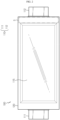
- FIG. 1 is a perspective view schematically showing a battery module according to an embodiment of the present disclosure.
- FIG. 2 is a side view schematically showing a secondary battery employed at the battery module according to an embodiment of the present disclosure.
- a battery module 200 includes a cell assembly 210 and a bus bar assembly 220.
- the cell assembly 210 may include a plurality of secondary batteries 100 arranged in the right and left direction.
- the secondary battery 100 may be a pouch-type secondary battery 100.
- the pouch-type secondary battery 100 may include an electrode assembly, an electrolyte, and a pouch 120.
- the pouch 120 may have an accommodation portion 115 of a concave shape.
- the accommodation assembly 115 may accommodate the electrode assembly (not shown) and the electrolyte (not shown).
- the pouch includes an outer insulation layer, a metal layer and an inner adhesive layer, and the inner adhesive layers are adhered to each other at a rim portion of the pouch 120 to form a sealing portion.
- terrace portions S may be respectively formed at both ends of the pouch 120 where a positive electrode lead 111 and a negative electrode lead 112 are formed.
- the electrode assembly is an assembly of an electrode and a separator, and at least one positive electrode plate and at least one negative electrode plate may disposed with a separator interposed therebetween.
- the positive electrode plate of the electrode assembly includes a positive electrode tab, and at least one positive electrode tab may be connected to the positive electrode lead 111.
- one end of the positive electrode lead 111 is connected to the positive electrode tab and the other end thereof is exposed out of the pouch 120.
- the exposed portion may function as an electrode terminal of the secondary battery 100, for example a positive electrode terminal of the secondary battery 100.
- the negative electrode plate of the electrode assembly includes a negative electrode tab, and at least one negative electrode tab may be connected to the negative electrode lead 112. Also, one end of the negative electrode lead 112 is connected to the negative electrode tab and the other end thereof is exposed out of the pouch 120. The exposed portion may serve as an electrode terminal of the secondary battery 100, for example a negative electrode terminal of the secondary battery 100.
- the positive electrode lead 111 and the negative electrode lead 112 may be formed at both ends opposite to each other based on the center of the secondary battery 100. That is, the positive electrode lead 111 may be provided at one end portion with respect to the center of the secondary battery 100. In addition, the negative electrode lead 112 may be provided at the other end portion with respect to the center of the secondary battery 100.
- each secondary battery 100 may be respectively configured so that the positive electrode lead 111 and the negative electrode lead 112 protrude forward and backward, respectively.
- the positive electrode lead 111 and the negative electrode lead 112 may be configured to have a plate form.
- the positive electrode lead 111 and the negative electrode lead 112 may protrude horizontally in a standing state so that their broad surfaces face left and right.
- the secondary battery 100 may be provided in plural in the battery module 200, and the plurality of secondary batteries 100 may be arranged to be stacked in at least one direction.
- a plurality of pouch-type secondary batteries 100 may be stacked one on another in parallel in the right and left direction.
- each pouch-type secondary battery 100 may be disposed to stand approximately perpendicular to the ground so that two broad surfaces positioned are respectively located at left and right and the sealing portions are located at upper, lower, front and rear portions, when viewed in the direction F (shown in FIG. 1 ).
- each secondary battery 100 may be configured in a vertically standing form.
- the upper, lower, front, rear, right and left directions are set based on the direction F, unless otherwise specified.
- the battery module 200 according to the present disclosure is not limited to the pouch-type secondary battery 100 described above, and various kinds of secondary batteries 100 known at the time of filing of this application may be employed.
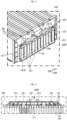
- FIG. 3 is a partially enlarged perspective view showing a portion C' of the battery module of FIG. 1 .
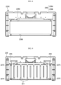
- FIG. 4 is a horizontally sectioned view schematically showing the battery module, taken along the line A-A' of FIG. 1 .
- the bus bar assembly 220 may be located at the front or rear of the cell assembly 210.
- the bus bar assembly 220 includes a plurality of bus bars 221 and a bus bar frame 225.
- the bus bar 221 may have a conductive material to electrically connect the plurality of secondary batteries 100. That is, the bus bar 221 may have a conductive material with relatively high electrical conductivity at a region that is in contact with the electrode lead 111 provided at each of the plurality of secondary batteries 100.
- the bus bar may have a copper alloy, or an aluminum alloy.
- the bus bar 221 may contact a plurality of electrode leads 111 of the same polarity or a plurality of electrode leads 112 of different polarities to electrically connect the plurality of secondary batteries 100.
- the bus bar 221 may have a metal plate shape.
- the metal plate shape may have a bar shape elongated in one direction.
- bus bar frame 225 may have a bus bar fixing portion 226 configured to fix a top end 221U and a bottom end 221B of the bus bar 221.
- an insert groove 228U having an upward recess elongated in the right and left direction and into which the top end 221U of the bus bar 221 is inserted and an insert groove 228B having a downward recess elongated in the right and left direction into which the bottom end 221B of the bus bar 221 is inserted may be formed at the outer side surface of the bus bar frame 225C.
- the battery pack according to the present disclosure may be applied to a vehicle such as an electric vehicle.
- the vehicle according to the present disclosure may include the above battery pack.
- Reference Signs 200 battery module 210: cell assembly 100: secondary battery 220: bus bar assembly 221: bus bar 225: bus bar frame 223: module bus bar 240: module terminal 226: bus bar fixing portion 229: bus bar open portion H1: opening H2: perforation hole 227: hook structure 228: insert groove 228P: fixing protrusion 221G: fitting groove 224: distance adjusting rod 228Z: compressing protrusion
Landscapes
- Chemical & Material Sciences (AREA)
- Chemical Kinetics & Catalysis (AREA)
- Electrochemistry (AREA)
- General Chemical & Material Sciences (AREA)
- Engineering & Computer Science (AREA)
- Microelectronics & Electronic Packaging (AREA)
- Manufacturing & Machinery (AREA)
- Inorganic Chemistry (AREA)
- Connection Of Batteries Or Terminals (AREA)
- Battery Mounting, Suspending (AREA)
Description
- The present disclosure relates to a battery module including a bus bar assembly, and more particularly, to a battery module having a reduced product manufacturing cost through a design change of an inner configuration.
- Secondary batteries currently commercialized include nickel cadmium batteries, nickel hydrogen batteries, nickel zinc batteries, lithium secondary batteries and so on. Among them, the lithium secondary batteries are more highlighted in comparison to nickel-based secondary batteries due to advantages such as free charging and discharging, caused by substantially no memory effect, very low self-discharge rate, and high energy density.
- The lithium secondary battery mainly uses lithium-based oxides and carbonaceous materials as a positive electrode active material and a negative electrode active material, respectively. The lithium secondary battery includes an electrode assembly in which a positive electrode plate coated with the positive electrode active material and a negative electrode plate coated with the negative electrode active material are disposed with a separator being interposed therebetween, and an exterior, namely a pouch exterior, sealably containing the electrode assembly together with an electrolyte.
- Generally, the lithium secondary battery may be classified into a can-type secondary battery in which an electrode assembly is included in a metal can and a pouch-type secondary battery in which an electrode assembly is included in a pouch made of an aluminum sheet, depending on the shape of the exterior.
- In recent years, secondary batteries have been widely used not only in small-sized devices such as portable electronic devices but also in medium-sized or large-sized devices such as vehicles and power storage devices. When the secondary batteries are used in the middle-sized or large-sized devices, a large number of secondary batteries are electrically connected to increase capacity and power. In particular, pouch-type secondary batteries are widely used for the middle-sized or large-sized devices since they may be easily stacked.
- In addition, in order for the secondary battery to be electrically connected inside the battery module, the electrode leads are connected to each other, and the connection portions are welded to maintain the connection. Further, the battery module may have parallel and/or serial electrical connections between the secondary batteries, and for this, one end of the electrode lead is fixed by welding or the like in contact with a bus bar for electrical connection between the secondary batteries.
- Also, the electrical connection between the secondary batteries is frequently performed by bonding the electrode leads to the bus bar. At this time, in order to electrically connect the secondary batteries in parallel, electrode leads of the same polarity are connected to each other. Also, in order to electrically connect the secondary batteries in series, electrode leads of different polarities are connected to each other.
- Further, in order to apply a plurality of the bus bars, the battery module includes a bus bar frame made of an insulating material on which the bus bars may be mounted.
- However, in the electrical connection of the plurality of secondary batteries applied to the existing battery module, namely among the secondary batteries applied, it is needed to change the kind of the bus bars and the shape of the bus bar frame whenever the number of secondary batteries electrically connected in series and the number of secondary batteries connected in parallel are changed.
- In addition, at the bus bar assemblies respectively applied to a front portion and a rear side of the battery module, the bus bar frames respectively applied to the front portion and the rear side should be designed to have different shapes depending on whether the module bus bar for mounting the module terminal is applied or not. Accordingly, it is necessary to fabricate two types of bus bar frames at one battery module, thereby causing an increase in the manufacturing cost.
- As a result, in the conventional technique, since the design of the bus bar frame should be changed frequently due to the design change of the battery module, the shapes of the bus bar and the bus bar frame are dualized more severely, and the redesign of the bus bar and the bus bar frame increases a design cost and requires the fabrication of a new mold. Moreover, due to the verification work for a fabricated product, the manufacturing cost is increased and the manufacturing time is elongated.
- Therefore, it is necessary to provide a battery module capable with a reduced manufacturing cost of a product through a design change of the inner configuration.
- The present disclosure is designed to solve the problems of the related art, and therefore the present disclosure is directed to providing a battery module, which may have a reduced manufacturing cost of a product through a design change of the inner configuration.
- These and other objects and advantages of the present disclosure may be understood from the following detailed description and will become more fully apparent from the exemplary embodiments of the present disclosure. Also, it will be easily understood that the objects and advantages of the present disclosure may be realized by the means shown in the appended claims and combinations thereof.
- In one aspect of the present disclosure, there is provided a battery module, comprising:
- a cell assembly including a plurality of secondary batteries that respectively have a plurality of electrode leads and are arranged to be stacked in at least one direction; and
- a bus bar assembly including a plurality of bus bars configured to electrically connect the plurality of secondary batteries and having at least one perforation hole into which the electrode leads are inserted, and a bus bar frame configured so that the plurality of bus bars are mounted to an outer side surface thereof,
- wherein the bus bar frame includes:
- a bus bar fixing portion having an insert space elongated in the right and left direction so that a position of the bus bar in the right and left direction is freely set, the bus bar fixing portion being configured to fix a top end and a bottom end of the bus bar; and
- a bus bar open portion opened so that the perforation hole of the bus bar is exposed inwards as the position of the bus bar in the right and left direction is changed.
- Also, the bus bar has a plate shape, and a perforation hole perforated in the front and rear direction is formed in the plate shape of the bus bar.
- Further, the bus bar fixing portion may have a hook structure whose hook shape is elongated in the right and left direction to press at least one of the top end and the bottom end of the bus bar in the inward direction.
- In addition, the bus bar fixing portion has an insert groove into which at least one of the top end and the bottom end of the bus bar is inserted, the insert groove having an upward or downward recess elongated in the right and left direction.
- Moreover, a plurality of fixing protrusions protruding toward the bus bar is formed at predetermined intervals on an inner surface of the insert groove.
- Also, a fitting groove having an upward recess is formed at an end of the bus bar so that the fixing protrusion is inserted therein.
- Further, a distance adjusting rod disposed between the plurality of bus bars and elongated in the right and left direction may be inserted into the insert groove.
- In addition, a compressing protrusion configured to press the bottom end of the bus bar in the outward direction may be formed at an inner surface of the insert groove.
- Moreover, the open portion of the bus bar may be opened in a length greater than the length of the bus bar in the right and left direction.
- Also, the open portion of the bus bar may have a single opening so that a rear surface of the plurality of bus bars mounted to the outer side surface is partially exposed inwards.
- In another aspect of the present disclosure, there is also provided a battery pack, comprising the battery module as above.
- In another aspect of the present disclosure, there is also provided a vehicle, comprising the battery pack as above.
- According to an embodiment of the present disclosure, since the battery module includes a bus bar fixing portion so that the position of the bus bar in the right and left direction may be freely set at the bus bar frame, a bus bar open portion is provided to form an opening through which the perforation hole of the bus bar is exposed inwards by changing the position of the bus bar in the right and left direction, without any influence due to the change of position of the bus bar caused by a design change. Therefore, it is possible to reset the position of the bus bar in the right and left direction without changing the design of the bus bar frame.
- Further, according to this embodiment of the present disclosure, since the bus bar fixing portion has a hook structure and an insert groove extending in the right and left direction so that the position to which the bus bar is fixed may be freely set, even though the size or position of the bus bar is changed due to a design change of the battery module, it is possible to use the existing bus bar frame without designing or manufacturing the bus bar frame newly, thereby greatly reducing the production cost of the battery module.
- In addition, according to an embodiment of the present disclosure, since the bus bar frame has a separate hook structure to fix the module bus bar, even though the module bus bar is not applied to the bus bar frame, it is possible to use the existing bus bar frame, without change the design of the bus bar frame. Accordingly, the bus bar frame may be applied to both front and rear sides of the battery module, thereby effectively reducing the design cost and manufacturing cost of the bus bar frame.
- Moreover, according to an embodiment of the present disclosure, since by using the coupling structure between a fixing protrusion formed in the insert groove provided at the bus bar fixing portion and a fitting groove formed at the bus bar, the present disclosure is possible to prevent the bus bar from moving in the right and left direction at the set position. In addition, the insert groove may guide the rotational movement so that a top end of the bus bar may be inserted into the hook structure after the bus bar is inserted into the insert groove, thereby improving the manufacturing efficiency of the bus bar assembly.
-
-
FIG. 1 is a perspective view schematically showing a battery module according to an embodiment of the present disclosure. -
FIG. 2 is a side view schematically showing a secondary battery employed at the battery module according to an embodiment of the present disclosure. -
FIG. 3 is a partially enlarged perspective view showing a portion C' of the battery module ofFIG. 1 . -
FIG. 4 is a horizontally sectioned view schematically showing the battery module, taken along the line A-A' ofFIG. 1 . -
FIG. 5 is a perspective view schematically showing a bus bar and a bus bar frame, employed at the battery module according to an embodiment of the present disclosure. -
FIG. 6 is a front view schematically showing a bus bar frame, employed at the battery module according to an embodiment of the present disclosure. -
FIG. 7 is a front view schematically showing a bus bar frame, employed at a battery module according to another embodiment of the present disclosure. -
FIG. 8 is a front view schematically showing a bus bar frame, employed at a battery module according to still another embodiment of the present disclosure. -
FIG. 9 is a front view schematically showing a bus bar frame located at the rear and a bus bar mounted thereto, at the battery module according to an embodiment of the present disclosure. -
FIG. 10 is a front view schematically showing a bus bar frame located at the rear and a bus bar mounted thereto, at a battery module according to another embodiment of the present disclosure. -
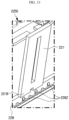
FIG. 11 is a perspective view schematically showing that the bus bar employed at the battery module according to an embodiment of the present disclosure is being mounted to the bus bar frame. -
FIG. 12 is a partial perspective view schematically showing that the bus bar employed at the battery module according to another embodiment of the present disclosure is mounted to the bus bar frame. -
FIG. 13 is a partial perspective view schematically showing that the bus bar employed at the battery module according to another embodiment of the present disclosure is mounted to the bus bar frame. - Hereinafter, preferred embodiments of the present disclosure will be described in detail with reference to the accompanying drawings. Prior to the description, it should be understood that the terms used in the specification and the appended claims should not be construed as limited to general and dictionary meanings, but interpreted based on the meanings and concepts corresponding to technical aspects of the present disclosure on the basis of the principle that the inventor is allowed to define terms appropriately for the best explanation.
- Therefore, the description proposed herein is just a preferable example for the purpose of illustrations only, not intended to limit the scope of the disclosure, so it should be understood that modifications could be made thereto within the scope of the appended claims.
-
FIG. 1 is a perspective view schematically showing a battery module according to an embodiment of the present disclosure. In addition,FIG. 2 is a side view schematically showing a secondary battery employed at the battery module according to an embodiment of the present disclosure. - Referring to
FIGS. 1 and2 , abattery module 200 according to an embodiment of the present disclosure includes acell assembly 210 and abus bar assembly 220. - Here, the
cell assembly 210 may include a plurality ofsecondary batteries 100 arranged in the right and left direction. - Specifically, the
secondary battery 100 may be a pouch-typesecondary battery 100. In particular, the pouch-typesecondary battery 100 may include an electrode assembly, an electrolyte, and apouch 120. - Here, the
pouch 120 may have anaccommodation portion 115 of a concave shape. Also, theaccommodation assembly 115 may accommodate the electrode assembly (not shown) and the electrolyte (not shown). In addition, the pouch includes an outer insulation layer, a metal layer and an inner adhesive layer, and the inner adhesive layers are adhered to each other at a rim portion of thepouch 120 to form a sealing portion. Further, terrace portions S may be respectively formed at both ends of thepouch 120 where apositive electrode lead 111 and anegative electrode lead 112 are formed. - In addition, the electrode assembly is an assembly of an electrode and a separator, and at least one positive electrode plate and at least one negative electrode plate may disposed with a separator interposed therebetween. The positive electrode plate of the electrode assembly includes a positive electrode tab, and at least one positive electrode tab may be connected to the
positive electrode lead 111. - Here, one end of the
positive electrode lead 111 is connected to the positive electrode tab and the other end thereof is exposed out of thepouch 120. The exposed portion may function as an electrode terminal of thesecondary battery 100, for example a positive electrode terminal of thesecondary battery 100. - In addition, the negative electrode plate of the electrode assembly includes a negative electrode tab, and at least one negative electrode tab may be connected to the
negative electrode lead 112. Also, one end of thenegative electrode lead 112 is connected to the negative electrode tab and the other end thereof is exposed out of thepouch 120. The exposed portion may serve as an electrode terminal of thesecondary battery 100, for example a negative electrode terminal of thesecondary battery 100. - Further, the
positive electrode lead 111 and thenegative electrode lead 112 may be formed at both ends opposite to each other based on the center of thesecondary battery 100. That is, thepositive electrode lead 111 may be provided at one end portion with respect to the center of thesecondary battery 100. In addition, thenegative electrode lead 112 may be provided at the other end portion with respect to the center of thesecondary battery 100. For example, as shown inFIGS. 1 and2 , eachsecondary battery 100 may be respectively configured so that thepositive electrode lead 111 and thenegative electrode lead 112 protrude forward and backward, respectively. - Thus, according to this configuration of the present disclosure, in one
secondary battery 100, there is no interference between thepositive electrode lead 111 and thenegative electrode lead 112, and thus it is possible to broaden the area of theelectrode lead 110. - Also, the
positive electrode lead 111 and thenegative electrode lead 112 may be configured to have a plate form. In particular, thepositive electrode lead 111 and thenegative electrode lead 112 may protrude horizontally in a standing state so that their broad surfaces face left and right. - In addition, the
secondary battery 100 may be provided in plural in thebattery module 200, and the plurality ofsecondary batteries 100 may be arranged to be stacked in at least one direction. For example, as shown inFIGS. 1 and2 , a plurality of pouch-typesecondary batteries 100 may be stacked one on another in parallel in the right and left direction. - At this time, each pouch-type
secondary battery 100 may be disposed to stand approximately perpendicular to the ground so that two broad surfaces positioned are respectively located at left and right and the sealing portions are located at upper, lower, front and rear portions, when viewed in the direction F (shown inFIG. 1 ). In other words, eachsecondary battery 100 may be configured in a vertically standing form. Meanwhile, in this specification, the upper, lower, front, rear, right and left directions are set based on the direction F, unless otherwise specified. - However, the
battery module 200 according to the present disclosure is not limited to the pouch-typesecondary battery 100 described above, and various kinds ofsecondary batteries 100 known at the time of filing of this application may be employed. -
FIG. 3 is a partially enlarged perspective view showing a portion C' of the battery module ofFIG. 1 . In addition,FIG. 4 is a horizontally sectioned view schematically showing the battery module, taken along the line A-A' ofFIG. 1 . - Referring to
FIGS. 3 and 4 together withFIG. 1 , thebus bar assembly 220 may be located at the front or rear of thecell assembly 210. In addition, thebus bar assembly 220 includes a plurality ofbus bars 221 and abus bar frame 225. - Specifically, the
bus bar 221 may have a conductive material to electrically connect the plurality ofsecondary batteries 100. That is, thebus bar 221 may have a conductive material with relatively high electrical conductivity at a region that is in contact with theelectrode lead 111 provided at each of the plurality ofsecondary batteries 100. For example, the bus bar may have a copper alloy, or an aluminum alloy. - For example, the
bus bar 221 may contact a plurality of electrode leads 111 of the same polarity or a plurality of electrode leads 112 of different polarities to electrically connect the plurality ofsecondary batteries 100. - Moreover, the
bus bar 221 may have a metal plate shape. Specifically, the metal plate shape may have a bar shape elongated in one direction. - Also, one end of the
bus bar 221 may be electrically connected to a sensing circuit board (not shown) by a sensing lead (not shown). Further, the sensing circuit board may include a measuring element for measuring voltage, current or the like of the plurality ofsecondary batteries 100. - In addition, the
bus bar frame 225 may be mounted to an outer side surface of thebus bar 221. In addition, thebus bar frame 225 may have an insulating material to be electrically insulated from thebus bar 221. For example, thebus bar frame 225 may have a plastic material. - Further, the
bus bar frame 225 may have a busbar fixing portion 226 configured to fix atop end 221U and abottom end 221B of thebus bar 221. - Specifically, the bus
bar fixing portion 226 may haveinsert spaces bus bar 221 in the right and left direction may be freely set. That is, thetop end 221U or thebottom end 221B of thebus bar 221 may be inserted into and fixed in theinsert spaces bar fixing portion 226. Accordingly, thebus bar 221 may be fixed suitable for a set position of thebus bar 221 in the right and left direction at the outer side surface of thebus bar frame 225. -
FIG. 5 is a perspective view schematically showing a bus bar and a bus bar frame, employed at the battery module according to an embodiment of the present disclosure. In addition,FIG. 6 is a front view schematically showing a bus bar frame, employed at the battery module according to an embodiment of the present disclosure. - Referring to
FIGS. 5 and6 together withFIG. 4 , at least one perforation hole H2 may be formed in the plurality ofbus bars 221 so that theelectrode lead 110 is inserted therein. In addition, thebus bar frame 225 may have a bus baropen portion 229 with an opening H1 so that the perforation hole H2 of thebus bar 221 is exposed inwards as the position of thebus bar 221 in the right and left direction is changed. Further, the perforation hole H2 may be formed through the plate shape of thebus bar 221 in the front and rear direction. - That is, the opening H1 may formed in the bus bar
open portion 229 so that thebus bar 221 mounted to thebus bar frame 225 may be partially exposed inwards even though the position of thebus bar 221 in the right and left direction is changed. Also, on occasions, the bus baropen portion 229 may have a plurality of openings (not shown). In addition, each of the plurality of openings may have a length greater than the length of onebus bar 221 in the right and left direction. - Alternatively, the bus bar
open portion 229 may have a single opening H1, rather than a plurality of openings. Further, the opening H1 may be formed wider than the sum of widths of the plurality ofbus bars 221 in the right and left direction. That is, a single opening H1 may be formed in the bus baropen portion 229 so that the rear surface of the plurality ofbus bars 221 mounted to the outer side surface is partially exposed inwards. - Thus, according to this configuration of the present disclosure, the bus
bar fixing portion 226 may be formed at thebus bar frame 225 so that the position of thebus bar 221 in the right and left direction may be freely set, and the bus baropen portion 229 is provided so that the opening H1 into which theelectrode lead 110 may be inserted may be provided without affecting the position change of thebus bar 221 in the right and left direction. Thus, it is possible to reset the position of thebus bar 221 in the right and left direction without changing the design of thebus bar frame 225. - Further, even though the size of the applied
bus bar 221 in the right and left direction is changed since the electrical connection configuration (a serial or parallel connection structure) of the plurality ofsecondary batteries 100 of thebattery module 200 is changed, thebus bar frame 225 may be applied using an existing form without changing the design of thebus bar frame 225. Accordingly, it is possible to reduce the manufacturing cost incurred in preparing thebattery module 200 of a new type. - Also, the
bus bar 221 may have a plate shape whose front and rear surfaces are relatively wider than its side surfaces. Further, at least one perforation hole H2 may be formed in the plate shape of thebus bar 221. In addition, theelectrode lead 110 of thesecondary battery 100 may be inserted into the perforation hole H2. - Referring to
FIGS. 3 and 4 again, an end of theelectrode lead 110 inserted into the perforation hole H2 of thebus bar 221 may be bent in the right and left direction, when viewed in the direction F (seeFIG. 1 ). Further, a side surface of the bent end of theelectrode lead 110 may be in contact with the front or rear surface of thebus bar 221. - Further, the end of the
electrode lead 110 inserted into the opening H1 of thebus bar frame 225 may protrude to face the side portion of thebus bar 221 in the right and left direction. Also, the end of theelectrode lead 110 may be bent in the right and left direction to contact the outer side surface of thebus bar 221. - For example, as shown in
FIG. 5 , thebus bar assembly 220 located at the front includes six bus bars 221. Also, the sixbus bars 221 may have a plate shape whose front and rear surfaces are wider than the side surfaces thereof. In addition, a single perforation hole H2 may be formed in thebus bar 221 so that theelectrode lead 110 is inserted therein. - Further, for example, as shown in
FIG. 3 , each of the sixbus bars 221 may be configured to contact the electrode leads 110 of foursecondary batteries 100. In addition, among the four electrode leads 110, two electrode leads 110 are inserted to face the side portion of thebus bar 221, and the remaining two electrode leads 110 may be inserted into the perforation hole H2 of thebus bar 221 to contact thebus bar 221. - Thus, according to this configuration of the present disclosure, since the
bus bar 221 has a plate shape and the perforation hole H2 is formed in the plate shape, the electrode leads 110 of the plurality ofsecondary batteries 100 are spaced apart and distributed at suitable intervals to ensure smooth contact between thebus bar 221 and theelectrode lead 110. - Referring to
FIGS. 5 and6 again, the busbar fixing portion 226 may have ahook structure 227 with a hook shape to press at least one of thetop end 221U and thebottom end 221B of thebus bar 221 in the inward direction. In addition, onehook structure 227 may be configured to secure thetop end 221U or thebottom end 221B of at least onebus bar 221. - For example, as shown in
FIG. 5 , the busbar fixing portion 226 may have fivehook structures 227 with a hook shape so as to press the top ends 221U of sixbus bars 221 in the inward direction. - In addition, an
insert space 227S elongated in the right and left direction to accommodate thetop end 221U of thebus bar 221 therein may be formed at an inner side of the hook portion of thehook structure 227. Further, thetop end 221U of thebus bar 221 inserted in theinsert space 227S may be configured to be movable in the right and left direction inside theinsert space 227S. - Thus, according to this configuration of the present disclosure, since the bus
bar fixing portion 226 has thehook structure 227 elongated in the right and left direction so that the position at which thebus bar 221 is to be fixed may freely set, even though the size or position of thebus bar 221 is changed due to a design change of thebattery module 200, the existingbus bar frame 225 may be used without designing or manufacturing thebus bar frame 225 newly. Accordingly, it is possible to save time and cost caused by the design change, thereby greatly reducing the production cost of thebattery module 200. -
FIG. 7 is a front view schematically showing a bus bar frame, employed at a battery module according to another embodiment of the present disclosure. - Referring to
FIG. 7 together withFIG. 5 , the busbar fixing portion 226 provided in thebattery module 200 according to another disclosure of the present disclosure may havehook structures top end 221U and thebottom end 221B of thebus bar 221 in the inward direction, respectively. - For example, as shown in
FIG. 7 , fivehook structures 227U configured to fix thetop end 221U of thebus bar 221 and fivehook structures 227B configured to fix thebottom end 221B of thebus bar 221 may be formed at the outer side surface of thebus bar frame 225B. - Thus, according to this configuration of the present disclosure, when the
hook structure 227 for respectively pressing thetop end 221U and thebottom end 221B of thebus bar 221 in the inward direction is provided, thetop end 221U and thebottom end 221B of thebus bar 221 may be firmly fixed to thebus bar frame 225. For this reason, it is possible to effectively prevent thebus bar 221 from being easily detached due to an external impact, and the durability of thebattery module 200 may be further enhanced. - Referring to
FIGS. 5 and6 again, the busbar fixing portion 226 may have aninsert groove 228 configured so that at least one of thetop end 221U and thebottom end 221B of thebus bar 221 may be inserted therein. Also, theinsert groove 228 may have an upward or downward recess elongated in the right and left direction. - In addition, the
insert groove 228 may have aninsert space 228S elongated in the right and left direction so that thetop end 221U or thebottom end 221B of thebus bar 221 is movable in the right and left direction in a state of being inserted therein. - However, the
bus bar 221 may be moved in the right and left direction only by the pressing force in the right and left direction, and after the position of thebus bar 221 is completely set, the position of thebus bar 221 may be fixed by the busbar fixing portion 226 not to move in the right and left direction. - For example, as shown in
FIG. 5 , aninsert groove 228 may be formed at the outer side surface of thebus bar frame 225 so that the bottom ends 221B of the sixbus bars 221 may be inserted and accommodated therein. Also, theinsert groove 228 may have a downward recess elongated in the right and left direction. In addition, thebus bar 221 inserted into theinsert groove 228 may have aninsert space 228S elongated in the right and left direction so as to be movable in the right and left direction. - Thus, according to this configuration of the present disclosure, since the
insert groove 228 elongated in the right and left direction is provided at the outer side of thebus bar frame 225, even though the size or position of thebus bar 221 is changed according to the design change of thebattery module 200, the existingbus bar frame 225 may be used without having to design or manufacture thebus bar frame 225 newly. Accordingly, it is possible to save time and cost caused by the design change, thereby greatly reducing the production cost of thebattery module 200. -
FIG. 8 is a front view schematically showing a bus bar frame, employed at a battery module according to still another embodiment of the present disclosure. - Referring to
FIG. 8 together withFIG. 5 , aninsert groove 228U having an upward recess elongated in the right and left direction and into which thetop end 221U of thebus bar 221 is inserted and aninsert groove 228B having a downward recess elongated in the right and left direction into which thebottom end 221B of thebus bar 221 is inserted may be formed at the outer side surface of thebus bar frame 225C. - In addition, the
bus bar frame 225C may be prepared by injection molding so that thebus bar 221 may be inserted into and fixed to theinsert groove 228 formed at thebus bar frame 225C. That is, after thebus bar 221 is inserted into a mold in advance, a molten material of thebus bar frame 225C is injected and then cured into a form of thebus bar frame 225C, so that thebus bar 221 is prepared to be inserted into thebus bar frame 225C. - Accordingly, according to this configuration of the present disclosure, since the
bus bar frame 225C has theinsert groove 228 configured so that thetop end 221U and thebottom end 221B of thebus bar 221 are movable in the right and left direction in a state of being accommodated, the position of thebus bar 221 or its size in the right and left direction may be freely set. -
FIG. 9 is a front view schematically showing a bus bar frame located at the rear and a bus bar mounted thereto, at the battery module according to an embodiment of the present disclosure. - Referring to
FIG. 9 together withFIG. 1 , amodule bus bar 223 connected to amodule terminal 240 may be mounted to thebus bar frame 225 mounted to the rear side of thebattery module 200. Specifically, themodule bus bar 223 may be configured to electrically connect the plurality ofsecondary batteries 100 and themodule terminal 240. Here, themodule terminal 240 may include a positiveelectrode module terminal 240A and a negativeelectrode module terminal 240B according to electrical polarities, as terminals for electrical connection between thebattery module 200 and an external device (not shown). - In addition, at least one
hook structure 227C for pressing and fixing a side end of themodule bus bar 223 may be formed at thebus bar frame 225. - For example, as shown in
FIG. 9 , fourhook structures 227C capable of pressing the side ends of two module bus bars 223 in the right and left direction may be formed at the outer side surface of thebus bar frame 225. - Thus, according to this configuration of the present disclosure, since the
hook structure 227C is separately formed at thebus bar frame 225 to fix themodule bus bar 223, even though themodule bus bar 223 is not applied to thebus bar frame 225, the existingbus bar frame 225 may be used without having to change the design of thebus bar frame 225. Also, since thebus bar frame 225 may be applied to both the front and rear of thebattery module 200 regardless of whether themodule terminal 240 is applied to the outer side surface of thebus bar frame 225, the design cost and manufacturing cost of thebus bar frame 225 can be effectively reduced. - Moreover, in addition to the
secondary battery 100 and thebus bar assembly 220, thebattery module 200 may further include end plates made of a metal material and located at an uppermost portion and a lowermost portion of thesecondary battery 100, a duct for allowing air to flow into or out of thebattery module 200, a sensing assembly having a sensing lead, a sensing circuit board and the like connected to theelectrode lead 110 of thesecondary battery 100 to sense the voltage or the like of thesecondary battery 100, and so on. -
FIG. 10 is a front view schematically showing a bus bar frame located at the rear and a bus bar mounted thereto, at a battery module according to another embodiment of the present disclosure. - Referring to
FIG. 10 together withFIGS. 1 and6 , abus bar assembly 220B of a battery module according to another embodiment may further include abus bar 221b having a relatively greater width in the right and left direction, compared to thebus bar 221 provided at thebus bar assembly 220 ofFIG. 9 . Also, two perforation holes H2 may be formed at thebus bar 221b. - That is, at least one
electrode lead 110 may be inserted into each of two perforation holes H2 formed at thebus bar 221b to contact the outer side surface of thebus bar 221. Accordingly, thebus bar 221B may be applied to connect sixsecondary batteries 100 in parallel. - In addition, the
bus bar frame 225 ofFIG. 10 may include a busbar fixing portion 226 having a plurality ofhook structures 227 and aninsert groove 228 capable of accommodating thebottom end 221B of the bus bar221b. - For example, as shown in
FIG. 10 , thebus bar assembly 220B may include threebus bars 221b respectively having two perforation holes H2 and two module bus bars 223B respectively one perforation hole H2. - Thus, according to this configuration of the present disclosure, since the bus
bar fixing portion 226 having thehook structure 227 and theinsert groove 228 is formed at thebus bar frame 225 and the bus baropen portion 229 having one opening is provided, it is possible to accommodate various types ofbus bars 221b with various sizes in the right and left direction. -
FIG. 11 is a perspective view schematically showing that the bus bar employed at the battery module according to an embodiment of the present disclosure is being mounted to the bus bar frame. - Referring to
FIG. 11 together withFIG. 5 , aninsert groove 228 may be formed at thebus bar frame 225 so that the bottom end of thebus bar 221 is inserted therein. Also, a plurality of fixingprotrusions 228P protruding toward thebus bar 221 may be formed on the inner surface of theinsert groove 228 at predetermined intervals. - Further, a
fitting groove 221G having an upward recess may be formed at the bottom end of thebus bar 221 so that the fixingprotrusion 228P is inserted therein. In addition, the fixingprotrusion 228P may be provided in plural so that the plurality of fixingprotrusions 228P are spaced at regular intervals along the inner surface of theinsert groove 228 in the right and left direction. - That is, in the
bus bar assembly 220, the bottom end of thebus bar 221 may be inserted into theinsert groove 228 so that thefitting groove 221G formed at the bottom end of thebus bar 221 and the fixingprotrusion 228P formed on the inner surface of theinsert groove 228 are coupled to each other. At this time, the bottom end of thebus bar 221 is inserted obliquely into theinsert groove 228, and then the top end of thebus bar 221 is pressed and rotated in the inward direction based on the bottom end of thebus bar 221 to be inserted into thehook structure 227. - Thus, according to this configuration of the present disclosure, by using the coupling structure of the fixing
protrusion 228P formed at theinsert groove 228 and thefitting groove 221G formed at thebus bar 221, it is possible to prevent thebus bar 221 from being moved at the set position in the right and left direction. Moreover, after thebus bar 221 is inserted into theinsert groove 228, it is possible to guide the rotational movement so that the top end of thebus bar 221 may be inserted into thehook structure 227, thereby enhancing the manufacturing efficiency. -
FIG. 12 is a partial perspective view schematically showing that the bus bar employed at the battery module according to another embodiment of the present disclosure is mounted to the bus bar frame. - Referring to
FIG. 12 , adistance adjusting rod 224 interposed between the plurality ofbus bars 221 and configured to set a distance between the plurality ofbus bars 221 may be inserted into theinsert groove 228 formed in at bus bar frame 225D. Specifically, thedistance adjusting rod 224 may have a bar shape elongated in the right and left direction. - In addition, the
distance adjusting rod 224 with a bar shape may have a width that allows to be inserted into theinsert groove 228. Further, the length of thedistance adjusting rod 224 in the right and left direction may be adjusted according to the size or number of the bus bars 221. -
FIG. 13 is a partial perspective view schematically showing that the bus bar employed at the battery module according to another embodiment of the present disclosure is mounted to the bus bar frame. - Referring to
FIG. 13 , aninsert groove 228 may be formed at thebus bar frame 225E according to another embodiment so that thebottom end 221B of thebus bar 221 is inserted therein. Also, a compressingprotrusion 228Z configured to press thebottom end 221B of thebus bar 221 in the outward direction may be formed at the inner surface of theinsert groove 228. - Further, a plurality of compressing
protrusions 228Z may be formed on the inner surface of theinsert groove 228 at predetermined intervals. In addition, the compressingprotrusion 228Z may be configured so that its outwardly protruding size gradually increases in the lower direction. - Thus, according to this configuration of the present disclosure, the compressing
protrusion 228Z formed at theinsert groove 228 may firmly fix thebus bar 221 to thebus bar frame 225 just by inserting thebottom end 221B of thebus bar 221 into theinsert groove 228 in the downward direction, and thus the durability of thebattery module 200 may be effectively increased. - Further, a battery pack according to the present disclosure may include at least one
battery module 200 according to the present disclosure. Also, the battery pack according to the present disclosure may further include, in addition to thebattery module 200, a pack case for accommodating thebattery module 200, and various devices for controlling charge and discharge of thebattery module 200, for example a battery management system (BMS), a current sensor, a fuse and the like. - In addition, the battery pack according to the present disclosure may be applied to a vehicle such as an electric vehicle. In other words, the vehicle according to the present disclosure may include the above battery pack.
- Meanwhile, even though the terms indicating directions such as upper, lower, left, right, front and rear directions are used in the specification, it is obvious to those skilled in the art that these merely represent relative positions for convenience in explanation and may vary based on a position of an observer or an object.
- The present disclosure has been described in detail. However, it should be understood that the detailed description and specific examples, while indicating preferred embodiments of the disclosure, are given by way of illustration only, since various changes and modifications within the scope of the claims will become apparent to those skilled in the art from this detailed description.
- Meanwhile, even though the terms indicating directions such as upper, lower, left, right, front and rear directions are used in the specification, it is obvious to those skilled in the art that these merely represent relative positions for convenience in explanation and may vary based on a position of an observer or an object.
- The present disclosure has been described in detail. However, it should be understood that the detailed description and specific examples, while indicating preferred embodiments of the disclosure, are given by way of illustration only, since various changes and modifications within the scope of the claims will become apparent to those skilled in the art from this detailed description.
Reference Signs 200: battery module 210: cell assembly 100: secondary battery 220: bus bar assembly 221: bus bar 225: bus bar frame 223: module bus bar 240: module terminal 226: bus bar fixing portion 229: bus bar open portion H1: opening H2: perforation hole 227: hook structure 228: insert groove 228P: fixing protrusion 221G: fitting groove 224: distance adjusting rod 228Z: compressing protrusion - The present disclosure relates to a battery module and a battery pack including the battery module. In addition, the battery module of the present disclosure are applicable to industries related to electronic devices or vehicles.
Claims (8)
- A battery module (200), comprising:a cell assembly (210) including a plurality of secondary batteries (100) that respectively have a plurality of electrode leads (111) and are arranged to be stacked in at least one direction; anda bus bar assembly (220) including a plurality of bus bars (221) configured to electrically connect the plurality of secondary batteries(100) and having at least one perforation hole (H2) into which the electrode leads (111) are inserted, and a bus bar frame (225) configured so that the plurality of bus bars (221) are mounted to an outer side surface thereof,wherein the bus bar frame (225) includes:a bus bar fixing portion (226) having an insert space elongated in the right and left direction so that a position of the bus bar (221) in the right and left direction is freely set, the bus bar fixing portion being configured to fix a top end (221U) and a bottom end (221B) of the bus bar (221); anda bus bar open portion (229) opened so that the perforation hole (H2) of the bus bar is exposed inwards as the position of the bus bar (221) in the right and left direction is changed, and wherein the bus bar (221) has a plate shape, andwherein a perforation hole (H2) perforated in the front and rear direction is formed in the plate shape of the bus bar (221), andwherein the bus bar fixing portion (226) has an insert groove (228) into which at least one of the top end (221U) and the bottom end (221B) of the bus bar (221) is inserted, the insert groove (228) having an upward or downward recess elongated in the right and left direction, andwherein a plurality of fixing protrusions (228P) protruding toward the bus bar (221) are formed at predetermined intervals on an inner surface of the insert groove (228), and a fitting groove (221G) having an upward recess is formed at an end of the bus bar (221) so that the fixing protrusion (228P) is inserted therein.
- The battery module (200) according to claim 1,
wherein the bus bar fixing portion (226) has a hook structure (227) whose hook shape is elongated in the right and left direction to press at least one of the top end (221U) and the bottom end (221B) of the bus bar (221) in the inward direction. - The battery module (200) according to claim 1,
wherein a distance adjusting rod (224) disposed between the plurality of bus bars (221) and elongated in the right and left direction is inserted into the insert groove (228). - The battery module (200) according to claim 1,
wherein a compressing protrusion (228Z) configured to press the bottom end of the bus bar (221) in the outward direction is formed at an inner surface of the insert groove (228). - The battery module (200) according to claim 1,
wherein the bus par open portion (229) is opened in a length greater than the length of the bus bar (221) in the right and left direction. - The battery module (200) according to claim 5,
wherein the bus par open portion (229) has a single opening so that a rear surface of the plurality of bus bars (221) mounted to the outer side surface is partially exposed inwards. - A battery pack, comprising at least one battery module (200) defined in any one of claims 1 to 6.
- A vehicle, comprising the battery pack defined in claim 7.
Applications Claiming Priority (2)
| Application Number | Priority Date | Filing Date | Title |
|---|---|---|---|
| KR1020170172515A KR102259416B1 (en) | 2017-12-14 | 2017-12-14 | Battery Module Having Bus bar Assembly |
| PCT/KR2018/015010 WO2019117514A1 (en) | 2017-12-14 | 2018-11-29 | Battery module comprising bus bar assembly |
Publications (3)
| Publication Number | Publication Date |
|---|---|
| EP3637503A1 EP3637503A1 (en) | 2020-04-15 |
| EP3637503A4 EP3637503A4 (en) | 2020-12-02 |
| EP3637503B1 true EP3637503B1 (en) | 2025-03-26 |
Family
ID=66820536
Family Applications (1)
| Application Number | Title | Priority Date | Filing Date |
|---|---|---|---|
| EP18889754.0A Active EP3637503B1 (en) | 2017-12-14 | 2018-11-29 | Battery module comprising bus bar assembly |
Country Status (9)
| Country | Link |
|---|---|
| US (1) | US11223093B2 (en) |
| EP (1) | EP3637503B1 (en) |
| JP (1) | JP7045588B2 (en) |
| KR (1) | KR102259416B1 (en) |
| CN (1) | CN110915024B (en) |
| ES (1) | ES3021240T3 (en) |
| HU (1) | HUE071177T2 (en) |
| PL (1) | PL3637503T3 (en) |
| WO (1) | WO2019117514A1 (en) |
Families Citing this family (50)
| Publication number | Priority date | Publication date | Assignee | Title |
|---|---|---|---|---|
| KR102532699B1 (en) * | 2019-06-25 | 2023-05-12 | 주식회사 엘지에너지솔루션 | Battery module and battery pack including the same |
| KR102541537B1 (en) * | 2019-06-25 | 2023-06-08 | 주식회사 엘지에너지솔루션 | Battery module and battery pack including the same |
| KR102583650B1 (en) * | 2019-07-01 | 2023-09-26 | 주식회사 엘지에너지솔루션 | Battery module and battery pack including the same |
| KR102785549B1 (en) * | 2019-08-02 | 2025-03-26 | 주식회사 엘지에너지솔루션 | Movable Bus bar assembly and Battery pack including the same, and secondary battery including the same |
| KR102860575B1 (en) * | 2019-08-23 | 2025-09-15 | 주식회사 엘지에너지솔루션 | Battery module and battery pack including the same |
| KR102792208B1 (en) * | 2019-09-11 | 2025-04-04 | 주식회사 엘지에너지솔루션 | Battery module and battery pack including the same |
| CN112582719B (en) * | 2019-09-29 | 2022-04-29 | 东莞新能源科技有限公司 | Battery module unit, battery module, energy storage system and electric vehicle |
| KR102795269B1 (en) * | 2019-10-07 | 2025-04-15 | 주식회사 엘지에너지솔루션 | Battery modules with mechanical connection structure between battery lead and busbar |
| KR102473336B1 (en) | 2019-10-07 | 2022-12-01 | 주식회사 엘지에너지솔루션 | Battery module and battery pack including the same |
| KR102772767B1 (en) | 2020-01-03 | 2025-02-24 | 주식회사 엘지에너지솔루션 | Battery module and battery pack including the same |
| KR102862762B1 (en) * | 2020-02-13 | 2025-09-19 | 주식회사 엘지에너지솔루션 | Battery module, battery pack and vehicle comprising the battery module |
| KR102862773B1 (en) * | 2020-02-17 | 2025-09-19 | 주식회사 엘지에너지솔루션 | Battery module, battery pack and vehicle comprising the battery module |
| WO2021206350A1 (en) * | 2020-04-09 | 2021-10-14 | 주식회사 엘지에너지솔루션 | Battery module and battery pack including same |
| KR20210132397A (en) | 2020-04-27 | 2021-11-04 | 주식회사 엘지에너지솔루션 | Battery module and battery pack including the same |
| CN111554848A (en) * | 2020-05-18 | 2020-08-18 | 桑顿新能源科技(长沙)有限公司 | Module box, soft pack lithium battery module |
| KR102802982B1 (en) * | 2020-07-06 | 2025-04-30 | 주식회사 엘지에너지솔루션 | Battery module and battery pack including the same |
| KR102892920B1 (en) | 2020-07-14 | 2025-11-28 | 주식회사 엘지에너지솔루션 | Battery pack and device including the same |
| JP7590130B2 (en) | 2020-07-17 | 2024-11-26 | 株式会社オートネットワーク技術研究所 | Wiring Module |
| KR102861724B1 (en) * | 2020-07-21 | 2025-09-17 | 주식회사 엘지에너지솔루션 | Battery module with improved electrode lead connection structure, and battery pack and vehicle comprising the same |
| KR102842539B1 (en) * | 2020-07-21 | 2025-08-04 | 주식회사 엘지에너지솔루션 | Battery module and battery pack including the same |
| KR102951291B1 (en) | 2020-07-22 | 2026-04-09 | 주식회사 엘지에너지솔루션 | Battery module having a simple connection structure between cell lead and voltage sensing member and battery pack including the same |
| KR102821825B1 (en) | 2020-07-22 | 2025-06-16 | 주식회사 엘지에너지솔루션 | Battery module having a simple connection structure between cell lead and voltage sensing member and battery pack including the same |
| KR20220040869A (en) * | 2020-09-24 | 2022-03-31 | 현대자동차주식회사 | Battery module and battery pack comprising the same |
| KR102848526B1 (en) * | 2020-10-26 | 2025-08-21 | 주식회사 엘지에너지솔루션 | Battery Module Sensing Unit, Battery Module, Battery Pack and Method for Battery Module Sensing Unit |
| KR102567485B1 (en) * | 2020-11-03 | 2023-08-17 | 한국단자공업 주식회사 | Electrical connecting apparatus for battery and making method the same |
| KR102917117B1 (en) * | 2020-11-05 | 2026-01-22 | 주식회사 엘지에너지솔루션 | Battery module and battery pack including the same |
| KR102866659B1 (en) * | 2020-11-10 | 2025-09-29 | 주식회사 엘지에너지솔루션 | A battery module with improved assembly structure of voltage sensing components and A battery pack including the same |
| KR102875637B1 (en) * | 2020-11-27 | 2025-10-22 | 주식회사 엘지에너지솔루션 | Battery Module, Battery Pack, and Energy Storage System |
| KR102929086B1 (en) * | 2020-12-29 | 2026-02-23 | 에스케이온 주식회사 | Battery module |
| CN116075974B (en) * | 2021-01-19 | 2026-03-06 | 株式会社Lg新能源 | Battery module and battery pack including the battery module |
| JP7459012B2 (en) * | 2021-04-23 | 2024-04-01 | プライムプラネットエナジー&ソリューションズ株式会社 | Connection structure of laminate cells, connection method of assembled batteries and laminate cells |
| EP4203171B1 (en) * | 2021-05-03 | 2025-10-15 | LG Energy Solution, Ltd. | Battery module and battery pack including same |
| US11973205B2 (en) | 2021-09-16 | 2024-04-30 | Lunar Energy, Inc. | Cell temperature regulation |
| KR102637525B1 (en) | 2021-10-26 | 2024-02-19 | 주식회사 엘지에너지솔루션 | Battery moule and battery pack including the same |
| KR102872638B1 (en) | 2021-11-08 | 2025-10-16 | 주식회사 엘지에너지솔루션 | Battery moule and battery pack including the same |
| KR102734328B1 (en) | 2021-11-12 | 2024-11-27 | 주식회사 엘지에너지솔루션 | Battery moule and battery pack including the same |
| KR102886196B1 (en) | 2021-11-12 | 2025-11-13 | 주식회사 엘지에너지솔루션 | Battery moule and battery pack including the same |
| KR102656950B1 (en) | 2021-11-12 | 2024-04-16 | 주식회사 엘지에너지솔루션 | Battery moule and battery pack including the same |
| CN216413212U (en) * | 2021-12-01 | 2022-04-29 | 宁德时代新能源科技股份有限公司 | Busbar assembly, battery and power consumption device |
| KR102927974B1 (en) * | 2021-12-17 | 2026-02-20 | 주식회사 엘지에너지솔루션 | Battery module with electrolyte leakage detection function and battery pack comprising the same |
| CN116565430A (en) * | 2022-01-27 | 2023-08-08 | 本田技研工业株式会社 | Battery pack and monomer assembly |
| CN116742290A (en) * | 2022-03-04 | 2023-09-12 | 比亚迪股份有限公司 | Battery cell assembly, battery pack and vehicle |
| KR102952040B1 (en) * | 2022-04-22 | 2026-04-14 | 현대모비스 주식회사 | Battery module assembly and method of manufacturing the same |
| KR102832837B1 (en) * | 2022-05-16 | 2025-07-09 | 주식회사 엘지에너지솔루션 | Battery pack and vehicle including the same |
| KR102452156B1 (en) * | 2022-06-16 | 2022-10-12 | 덕양산업 주식회사 | Bracket for fixing a bus bar for battery pack |
| KR102915631B1 (en) * | 2022-11-17 | 2026-01-21 | 주식회사 엘지에너지솔루션 | Battery module including busbar frame separated from top and bottom and assembly method having the same |
| KR102817210B1 (en) * | 2023-07-27 | 2025-06-09 | 주식회사 카펙발레오 | Bus bar support bracket, battery pack using the same, and vehicle equipped therewith |
| EP4601089A1 (en) * | 2024-02-06 | 2025-08-13 | LG Energy Solution, Ltd. | Battery cell assembly, battery pack, and transportation device comprising the same |
| KR20260004016A (en) * | 2024-07-01 | 2026-01-08 | 주식회사 엘지에너지솔루션 | Busbar frame assembly and battery module including the same |
| KR20260046649A (en) * | 2024-09-30 | 2026-04-07 | 주식회사 엘지에너지솔루션 | Battery module and battery pack and vehicle including the same |
Family Cites Families (35)
| Publication number | Priority date | Publication date | Assignee | Title |
|---|---|---|---|---|
| JP5449814B2 (en) | 2009-03-25 | 2014-03-19 | 三洋電機株式会社 | Assembled battery |
| US8580423B2 (en) | 2009-10-22 | 2013-11-12 | Samsung Sdi Co., Ltd. | Bus bar holder and battery pack including the same |
| KR101201747B1 (en) | 2010-05-24 | 2012-11-15 | 에스비리모티브 주식회사 | Battery module |
| KR101217564B1 (en) | 2010-08-16 | 2013-01-02 | 주식회사 엘지화학 | Voltage Sensing Assembly and Battery Module Employed with the Same |
| KR102024002B1 (en) * | 2012-07-05 | 2019-09-23 | 에스케이이노베이션 주식회사 | Battery pack |
| JP2014032949A (en) * | 2012-07-13 | 2014-02-20 | Toyota Motor Corp | Power storage device storage and bus bar unit |
| JP6234929B2 (en) | 2012-08-30 | 2017-11-22 | 三洋電機株式会社 | Power supply device, vehicle equipped with power supply device, power storage device, and method of manufacturing power supply device |
| KR101732285B1 (en) | 2012-11-09 | 2017-05-02 | 닛산 지도우샤 가부시키가이샤 | Assembled battery and method for manufacturing assembled battery |
| KR20140060633A (en) * | 2012-11-12 | 2014-05-21 | 주식회사 엘지화학 | Battery module having bus bar assembly and battery pack comprising the same |
| JP6107091B2 (en) | 2012-12-04 | 2017-04-05 | 日産自動車株式会社 | Assembled battery and manufacturing method of assembled battery |
| JP2014116160A (en) | 2012-12-07 | 2014-06-26 | Yazaki Corp | Power supply device |
| KR102046122B1 (en) * | 2013-05-21 | 2019-11-19 | 에스케이이노베이션 주식회사 | PCB connecting unit for Battery modularizaton and Method for manufacturing Battery module and Battery module made by the method |
| JP6145314B2 (en) * | 2013-05-29 | 2017-06-07 | 矢崎総業株式会社 | Bus bar module and power supply |
| JP6016737B2 (en) | 2013-08-29 | 2016-10-26 | 古河電気工業株式会社 | In-battery wiring module of battery pack |
| JP6011876B2 (en) | 2013-09-13 | 2016-10-19 | 株式会社オートネットワーク技術研究所 | Power storage module |
| KR101632339B1 (en) | 2013-10-31 | 2016-06-21 | 주식회사 엘지화학 | Battery pack assembly can absorb the external shock |
| KR102263304B1 (en) | 2013-11-05 | 2021-06-15 | 타이코에이엠피 주식회사 | A battery cell connecting board |
| KR101667519B1 (en) * | 2013-12-17 | 2016-10-28 | 주식회사 엘지화학 | Battery Module having Bus Bar employed with External Input-Output Terminal |
| WO2015152527A1 (en) * | 2014-03-31 | 2015-10-08 | 주식회사 엘지화학 | Battery module and battery pack comprising same |
| JP2015230892A (en) * | 2014-06-09 | 2015-12-21 | ソニー株式会社 | Battery module, power storage device, power storage system, electronic apparatus, electric vehicle and power system |
| KR101640100B1 (en) | 2014-11-10 | 2016-07-18 | 한국단자공업 주식회사 | Series connection apparatus of battery module |
| US9755212B2 (en) | 2014-11-11 | 2017-09-05 | Ford Global Technologies, Llc | Traction battery busbar carriers for pouch battery cells |
| KR101797687B1 (en) | 2014-12-22 | 2017-11-15 | 주식회사 엘지화학 | Battery Cell Interconnection Board Having Packing for Protecting Inflow of Foreign Substances |
| KR102381777B1 (en) * | 2015-02-25 | 2022-04-01 | 삼성에스디아이 주식회사 | Battery pack |
| DE102015217644A1 (en) * | 2015-09-15 | 2017-03-16 | Robert Bosch Gmbh | Cover element of a battery module housing, battery module with such a cover element and method for its production and battery |
| JP6309499B2 (en) | 2015-09-18 | 2018-04-11 | 矢崎総業株式会社 | Bus bar module and battery pack |
| JP6717581B2 (en) | 2015-10-22 | 2020-07-01 | 株式会社エンビジョンAescジャパン | Battery pack and spacer for battery pack |
| KR102047482B1 (en) * | 2015-10-30 | 2019-12-02 | 주식회사 엘지화학 | Battery module and battery pack including the same |
| KR200491844Y1 (en) | 2015-11-12 | 2020-06-16 | 한국단자공업 주식회사 | Series connection apparatus of battery module |
| KR102032356B1 (en) | 2015-12-07 | 2019-11-08 | 주식회사 엘지화학 | Voltage Sensing Block for Battery Module |
| KR200485016Y1 (en) | 2015-12-11 | 2017-12-12 | 한국단자공업 주식회사 | Series connection apparatus of battery module |
| KR102093943B1 (en) | 2016-02-12 | 2020-03-26 | 주식회사 엘지화학 | Battery module, battery pack comprising the battery module and vehicle comprising the battery pack |
| KR102093944B1 (en) | 2016-02-12 | 2020-03-26 | 주식회사 엘지화학 | Battery module, battery pack comprising the battery module and vehicle comprising the battery pack |
| KR102034208B1 (en) * | 2016-03-03 | 2019-10-18 | 주식회사 엘지화학 | Battery module, battery pack the battery module and vehicle comprising the battery pack |
| JP6650326B2 (en) | 2016-04-01 | 2020-02-19 | 株式会社エンビジョンAescジャパン | Battery pack and method of manufacturing battery pack |
-
2017
- 2017-12-14 KR KR1020170172515A patent/KR102259416B1/en active Active
-
2018
- 2018-11-29 CN CN201880036425.4A patent/CN110915024B/en active Active
- 2018-11-29 PL PL18889754.0T patent/PL3637503T3/en unknown
- 2018-11-29 HU HUE18889754A patent/HUE071177T2/en unknown
- 2018-11-29 ES ES18889754T patent/ES3021240T3/en active Active
- 2018-11-29 JP JP2019560340A patent/JP7045588B2/en active Active
- 2018-11-29 US US16/611,353 patent/US11223093B2/en active Active
- 2018-11-29 EP EP18889754.0A patent/EP3637503B1/en active Active
- 2018-11-29 WO PCT/KR2018/015010 patent/WO2019117514A1/en not_active Ceased
Also Published As
| Publication number | Publication date |
|---|---|
| ES3021240T3 (en) | 2025-05-26 |
| EP3637503A4 (en) | 2020-12-02 |
| US11223093B2 (en) | 2022-01-11 |
| JP7045588B2 (en) | 2022-04-01 |
| US20200144580A1 (en) | 2020-05-07 |
| KR102259416B1 (en) | 2021-06-01 |
| PL3637503T3 (en) | 2025-06-09 |
| EP3637503A1 (en) | 2020-04-15 |
| KR20190071454A (en) | 2019-06-24 |
| CN110915024A (en) | 2020-03-24 |
| WO2019117514A1 (en) | 2019-06-20 |
| HUE071177T2 (en) | 2025-08-28 |
| CN110915024B (en) | 2022-06-10 |
| JP2020518988A (en) | 2020-06-25 |
Similar Documents
| Publication | Publication Date | Title |
|---|---|---|
| EP3637503B1 (en) | Battery module comprising bus bar assembly | |
| KR102392767B1 (en) | Battery Module Having Inner Cover | |
| CN110710051B (en) | Battery pack | |
| US10096867B2 (en) | Compact secondary battery module integrated with BMS | |
| EP2282363B1 (en) | Battery pack comprising unit batteries disposed in a spacer | |
| EP3937299A1 (en) | Battery module and battery pack | |
| KR102792413B1 (en) | Battery Module Having Bus bar and Battery Pack and Vehicle | |
| CN110770946A (en) | Easily assembled battery module including bus bar frame | |
| EP3035434A1 (en) | Battery module | |
| US11205817B2 (en) | Battery pack | |
| EP2849262A1 (en) | Battery cell having amorphous structure and battery module comprising same | |
| US20130045401A1 (en) | Battery pack and battery module comprising the same | |
| CN109891626A (en) | Battery pack | |
| US11984612B2 (en) | Battery module comprising module housing | |
| JP6594455B2 (en) | Battery module with wire fixing rib | |
| KR102937187B1 (en) | Battery Module and Battery Pack Having the Same and Vehicle | |
| KR102809421B1 (en) | Battery Module, Battery Pack Having the Same, and Vehicle | |
| JP4744096B2 (en) | Pack battery | |
| CN108023042A (en) | Battery frame for reception bag packed battery | |
| JP6338905B2 (en) | Battery system | |
| KR101839653B1 (en) | Compact secondary battery module | |
| KR101658587B1 (en) | Lithium Secondary Battery and Battery Pack Comprising The Same | |
| JP7566029B2 (en) | Battery module, battery pack including same, and automobile | |
| EP4175036A1 (en) | Battery module, battery pack, and power storage device | |
| KR20260056765A (en) | A terminal busbar and a battery pack provided therewith |
Legal Events
| Date | Code | Title | Description |
|---|---|---|---|
| STAA | Information on the status of an ep patent application or granted ep patent |
Free format text: STATUS: THE INTERNATIONAL PUBLICATION HAS BEEN MADE |
|
| PUAI | Public reference made under article 153(3) epc to a published international application that has entered the european phase |
Free format text: ORIGINAL CODE: 0009012 |
|
| STAA | Information on the status of an ep patent application or granted ep patent |
Free format text: STATUS: REQUEST FOR EXAMINATION WAS MADE |
|
| 17P | Request for examination filed |
Effective date: 20200108 |
|
| AK | Designated contracting states |
Kind code of ref document: A1 Designated state(s): AL AT BE BG CH CY CZ DE DK EE ES FI FR GB GR HR HU IE IS IT LI LT LU LV MC MK MT NL NO PL PT RO RS SE SI SK SM TR |
|
| AX | Request for extension of the european patent |
Extension state: BA ME |
|
| A4 | Supplementary search report drawn up and despatched |
Effective date: 20201029 |
|
| RIC1 | Information provided on ipc code assigned before grant |
Ipc: H01M 2/10 20060101ALI20201023BHEP Ipc: H01M 2/20 20060101AFI20201023BHEP |
|
| DAV | Request for validation of the european patent (deleted) | ||
| DAX | Request for extension of the european patent (deleted) | ||
| RAP1 | Party data changed (applicant data changed or rights of an application transferred) |
Owner name: LG ENERGY SOLUTION LTD. |
|
| RAP3 | Party data changed (applicant data changed or rights of an application transferred) |
Owner name: LG ENERGY SOLUTION, LTD. |
|
| STAA | Information on the status of an ep patent application or granted ep patent |
Free format text: STATUS: EXAMINATION IS IN PROGRESS |
|
| 17Q | First examination report despatched |
Effective date: 20230621 |
|
| REG | Reference to a national code |
Ref country code: DE Ref legal event code: R079 Free format text: PREVIOUS MAIN CLASS: H01M0002200000 Ipc: H01M0050211000 Ref document number: 602018080583 Country of ref document: DE |
|
| GRAP | Despatch of communication of intention to grant a patent |
Free format text: ORIGINAL CODE: EPIDOSNIGR1 |
|
| STAA | Information on the status of an ep patent application or granted ep patent |
Free format text: STATUS: GRANT OF PATENT IS INTENDED |
|
| RIC1 | Information provided on ipc code assigned before grant |
Ipc: H01M 50/507 20210101ALI20241108BHEP Ipc: H01M 50/211 20210101AFI20241108BHEP |
|
| INTG | Intention to grant announced |
Effective date: 20241120 |
|
| P01 | Opt-out of the competence of the unified patent court (upc) registered |
Free format text: CASE NUMBER: APP_65640/2024 Effective date: 20241212 |
|
| GRAS | Grant fee paid |
Free format text: ORIGINAL CODE: EPIDOSNIGR3 |
|
| GRAA | (expected) grant |
Free format text: ORIGINAL CODE: 0009210 |
|
| STAA | Information on the status of an ep patent application or granted ep patent |
Free format text: STATUS: THE PATENT HAS BEEN GRANTED |
|
| AK | Designated contracting states |
Kind code of ref document: B1 Designated state(s): AL AT BE BG CH CY CZ DE DK EE ES FI FR GB GR HR HU IE IS IT LI LT LU LV MC MK MT NL NO PL PT RO RS SE SI SK SM TR |
|
| REG | Reference to a national code |
Ref country code: GB Ref legal event code: FG4D |
|
| REG | Reference to a national code |
Ref country code: CH Ref legal event code: EP |
|
| REG | Reference to a national code |
Ref country code: DE Ref legal event code: R096 Ref document number: 602018080583 Country of ref document: DE |
|
| REG | Reference to a national code |
Ref country code: IE Ref legal event code: FG4D |
|
| REG | Reference to a national code |
Ref country code: SE Ref legal event code: TRGR |
|
| REG | Reference to a national code |
Ref country code: ES Ref legal event code: FG2A Ref document number: 3021240 Country of ref document: ES Kind code of ref document: T3 Effective date: 20250526 |
|
| PG25 | Lapsed in a contracting state [announced via postgrant information from national office to epo] |
Ref country code: RS Free format text: LAPSE BECAUSE OF FAILURE TO SUBMIT A TRANSLATION OF THE DESCRIPTION OR TO PAY THE FEE WITHIN THE PRESCRIBED TIME-LIMIT Effective date: 20250626 |
|
| PG25 | Lapsed in a contracting state [announced via postgrant information from national office to epo] |
Ref country code: FI Free format text: LAPSE BECAUSE OF FAILURE TO SUBMIT A TRANSLATION OF THE DESCRIPTION OR TO PAY THE FEE WITHIN THE PRESCRIBED TIME-LIMIT Effective date: 20250326 |
|
| REG | Reference to a national code |
Ref country code: LT Ref legal event code: MG9D |
|
| PG25 | Lapsed in a contracting state [announced via postgrant information from national office to epo] |
Ref country code: NO Free format text: LAPSE BECAUSE OF FAILURE TO SUBMIT A TRANSLATION OF THE DESCRIPTION OR TO PAY THE FEE WITHIN THE PRESCRIBED TIME-LIMIT Effective date: 20250626 |
|
| PG25 | Lapsed in a contracting state [announced via postgrant information from national office to epo] |
Ref country code: HR Free format text: LAPSE BECAUSE OF FAILURE TO SUBMIT A TRANSLATION OF THE DESCRIPTION OR TO PAY THE FEE WITHIN THE PRESCRIBED TIME-LIMIT Effective date: 20250326 |
|
| PG25 | Lapsed in a contracting state [announced via postgrant information from national office to epo] |
Ref country code: LV Free format text: LAPSE BECAUSE OF FAILURE TO SUBMIT A TRANSLATION OF THE DESCRIPTION OR TO PAY THE FEE WITHIN THE PRESCRIBED TIME-LIMIT Effective date: 20250326 |
|
| PG25 | Lapsed in a contracting state [announced via postgrant information from national office to epo] |
Ref country code: GR Free format text: LAPSE BECAUSE OF FAILURE TO SUBMIT A TRANSLATION OF THE DESCRIPTION OR TO PAY THE FEE WITHIN THE PRESCRIBED TIME-LIMIT Effective date: 20250627 Ref country code: BG Free format text: LAPSE BECAUSE OF FAILURE TO SUBMIT A TRANSLATION OF THE DESCRIPTION OR TO PAY THE FEE WITHIN THE PRESCRIBED TIME-LIMIT Effective date: 20250326 |
|
| REG | Reference to a national code |
Ref country code: NL Ref legal event code: MP Effective date: 20250326 |
|
| PG25 | Lapsed in a contracting state [announced via postgrant information from national office to epo] |
Ref country code: NL Free format text: LAPSE BECAUSE OF FAILURE TO SUBMIT A TRANSLATION OF THE DESCRIPTION OR TO PAY THE FEE WITHIN THE PRESCRIBED TIME-LIMIT Effective date: 20250326 |
|
| REG | Reference to a national code |
Ref country code: HU Ref legal event code: AG4A Ref document number: E071177 Country of ref document: HU |
|
| REG | Reference to a national code |
Ref country code: AT Ref legal event code: MK05 Ref document number: 1779883 Country of ref document: AT Kind code of ref document: T Effective date: 20250326 |
|
| PG25 | Lapsed in a contracting state [announced via postgrant information from national office to epo] |
Ref country code: SM Free format text: LAPSE BECAUSE OF FAILURE TO SUBMIT A TRANSLATION OF THE DESCRIPTION OR TO PAY THE FEE WITHIN THE PRESCRIBED TIME-LIMIT Effective date: 20250326 |
|
| PG25 | Lapsed in a contracting state [announced via postgrant information from national office to epo] |
Ref country code: PT Free format text: LAPSE BECAUSE OF FAILURE TO SUBMIT A TRANSLATION OF THE DESCRIPTION OR TO PAY THE FEE WITHIN THE PRESCRIBED TIME-LIMIT Effective date: 20250728 |
|
| PG25 | Lapsed in a contracting state [announced via postgrant information from national office to epo] |
Ref country code: IT Free format text: LAPSE BECAUSE OF FAILURE TO SUBMIT A TRANSLATION OF THE DESCRIPTION OR TO PAY THE FEE WITHIN THE PRESCRIBED TIME-LIMIT Effective date: 20250326 |
|
| PG25 | Lapsed in a contracting state [announced via postgrant information from national office to epo] |
Ref country code: AT Free format text: LAPSE BECAUSE OF FAILURE TO SUBMIT A TRANSLATION OF THE DESCRIPTION OR TO PAY THE FEE WITHIN THE PRESCRIBED TIME-LIMIT Effective date: 20250326 |
|
| PG25 | Lapsed in a contracting state [announced via postgrant information from national office to epo] |
Ref country code: EE Free format text: LAPSE BECAUSE OF FAILURE TO SUBMIT A TRANSLATION OF THE DESCRIPTION OR TO PAY THE FEE WITHIN THE PRESCRIBED TIME-LIMIT Effective date: 20250326 |
|
| PG25 | Lapsed in a contracting state [announced via postgrant information from national office to epo] |
Ref country code: RO Free format text: LAPSE BECAUSE OF FAILURE TO SUBMIT A TRANSLATION OF THE DESCRIPTION OR TO PAY THE FEE WITHIN THE PRESCRIBED TIME-LIMIT Effective date: 20250326 |
|
| PG25 | Lapsed in a contracting state [announced via postgrant information from national office to epo] |
Ref country code: SK Free format text: LAPSE BECAUSE OF FAILURE TO SUBMIT A TRANSLATION OF THE DESCRIPTION OR TO PAY THE FEE WITHIN THE PRESCRIBED TIME-LIMIT Effective date: 20250326 |
|
| PG25 | Lapsed in a contracting state [announced via postgrant information from national office to epo] |
Ref country code: IS Free format text: LAPSE BECAUSE OF FAILURE TO SUBMIT A TRANSLATION OF THE DESCRIPTION OR TO PAY THE FEE WITHIN THE PRESCRIBED TIME-LIMIT Effective date: 20250726 |
|
| PGFP | Annual fee paid to national office [announced via postgrant information from national office to epo] |
Ref country code: HU Payment date: 20251127 Year of fee payment: 8 |
|
| REG | Reference to a national code |
Ref country code: DE Ref legal event code: R097 Ref document number: 602018080583 Country of ref document: DE |
|
| PGFP | Annual fee paid to national office [announced via postgrant information from national office to epo] |
Ref country code: DE Payment date: 20251020 Year of fee payment: 8 |
|
| PGFP | Annual fee paid to national office [announced via postgrant information from national office to epo] |
Ref country code: GB Payment date: 20251023 Year of fee payment: 8 |
|
| PG25 | Lapsed in a contracting state [announced via postgrant information from national office to epo] |
Ref country code: DK Free format text: LAPSE BECAUSE OF FAILURE TO SUBMIT A TRANSLATION OF THE DESCRIPTION OR TO PAY THE FEE WITHIN THE PRESCRIBED TIME-LIMIT Effective date: 20250326 |
|
| PGFP | Annual fee paid to national office [announced via postgrant information from national office to epo] |
Ref country code: FR Payment date: 20251021 Year of fee payment: 8 |
|
| PGFP | Annual fee paid to national office [announced via postgrant information from national office to epo] |
Ref country code: BE Payment date: 20251020 Year of fee payment: 8 |
|
| PGFP | Annual fee paid to national office [announced via postgrant information from national office to epo] |
Ref country code: SE Payment date: 20251021 Year of fee payment: 8 |
|
| PG25 | Lapsed in a contracting state [announced via postgrant information from national office to epo] |
Ref country code: CZ Free format text: LAPSE BECAUSE OF FAILURE TO SUBMIT A TRANSLATION OF THE DESCRIPTION OR TO PAY THE FEE WITHIN THE PRESCRIBED TIME-LIMIT Effective date: 20250326 |
|
| PGFP | Annual fee paid to national office [announced via postgrant information from national office to epo] |
Ref country code: PL Payment date: 20251020 Year of fee payment: 8 |
|
| PGFP | Annual fee paid to national office [announced via postgrant information from national office to epo] |
Ref country code: ES Payment date: 20251215 Year of fee payment: 8 |
|
| PLBE | No opposition filed within time limit |
Free format text: ORIGINAL CODE: 0009261 |
|
| STAA | Information on the status of an ep patent application or granted ep patent |
Free format text: STATUS: NO OPPOSITION FILED WITHIN TIME LIMIT |
|
| REG | Reference to a national code |
Ref country code: CH Ref legal event code: L10 Free format text: ST27 STATUS EVENT CODE: U-0-0-L10-L00 (AS PROVIDED BY THE NATIONAL OFFICE) Effective date: 20260211 |
|
| 26N | No opposition filed |
Effective date: 20260105 |