EP3637013A1 - Combined device for simultaneous heating of domestic water and water for heating a room - Google Patents
Combined device for simultaneous heating of domestic water and water for heating a room Download PDFInfo
- Publication number
- EP3637013A1 EP3637013A1 EP19200350.7A EP19200350A EP3637013A1 EP 3637013 A1 EP3637013 A1 EP 3637013A1 EP 19200350 A EP19200350 A EP 19200350A EP 3637013 A1 EP3637013 A1 EP 3637013A1
- Authority
- EP
- European Patent Office
- Prior art keywords
- water
- heating
- circuit
- storage tank
- combined device
- Prior art date
- Legal status (The legal status is an assumption and is not a legal conclusion. Google has not performed a legal analysis and makes no representation as to the accuracy of the status listed.)
- Granted
Links
- XLYOFNOQVPJJNP-UHFFFAOYSA-N water Substances O XLYOFNOQVPJJNP-UHFFFAOYSA-N 0.000 title claims abstract description 354
- 238000010438 heat treatment Methods 0.000 title claims abstract description 175
- 239000008236 heating water Substances 0.000 claims abstract description 133
- 239000013529 heat transfer fluid Substances 0.000 claims abstract description 47
- 239000012530 fluid Substances 0.000 claims abstract description 40
- 238000003860 storage Methods 0.000 claims description 209
- 238000009826 distribution Methods 0.000 claims description 47
- 238000009434 installation Methods 0.000 claims description 46
- 238000004891 communication Methods 0.000 claims description 24
- 241001631457 Cannula Species 0.000 claims description 18
- 238000004519 manufacturing process Methods 0.000 claims description 4
- 230000001105 regulatory effect Effects 0.000 description 5
- 238000003756 stirring Methods 0.000 description 5
- 238000000034 method Methods 0.000 description 4
- 238000013517 stratification Methods 0.000 description 4
- 238000009833 condensation Methods 0.000 description 3
- 230000005494 condensation Effects 0.000 description 3
- 238000010586 diagram Methods 0.000 description 3
- 238000002156 mixing Methods 0.000 description 3
- RYGMFSIKBFXOCR-UHFFFAOYSA-N Copper Chemical compound [Cu] RYGMFSIKBFXOCR-UHFFFAOYSA-N 0.000 description 2
- 238000000429 assembly Methods 0.000 description 2
- 230000008901 benefit Effects 0.000 description 2
- 238000010276 construction Methods 0.000 description 2
- 229910052802 copper Inorganic materials 0.000 description 2
- 239000010949 copper Substances 0.000 description 2
- 238000005265 energy consumption Methods 0.000 description 2
- 210000000056 organ Anatomy 0.000 description 2
- 230000002093 peripheral effect Effects 0.000 description 2
- BASFCYQUMIYNBI-UHFFFAOYSA-N platinum Chemical compound [Pt] BASFCYQUMIYNBI-UHFFFAOYSA-N 0.000 description 2
- 238000010257 thawing Methods 0.000 description 2
- 230000009471 action Effects 0.000 description 1
- WYTGDNHDOZPMIW-RCBQFDQVSA-N alstonine Natural products C1=CC2=C3C=CC=CC3=NC2=C2N1C[C@H]1[C@H](C)OC=C(C(=O)OC)[C@H]1C2 WYTGDNHDOZPMIW-RCBQFDQVSA-N 0.000 description 1
- 230000000712 assembly Effects 0.000 description 1
- 230000005540 biological transmission Effects 0.000 description 1
- 230000000295 complement effect Effects 0.000 description 1
- 238000011109 contamination Methods 0.000 description 1
- 239000002826 coolant Substances 0.000 description 1
- 238000005520 cutting process Methods 0.000 description 1
- 230000000593 degrading effect Effects 0.000 description 1
- 230000006866 deterioration Effects 0.000 description 1
- 238000010494 dissociation reaction Methods 0.000 description 1
- 230000005593 dissociations Effects 0.000 description 1
- 230000009977 dual effect Effects 0.000 description 1
- 230000000694 effects Effects 0.000 description 1
- 235000021183 entrée Nutrition 0.000 description 1
- 230000010354 integration Effects 0.000 description 1
- 238000005457 optimization Methods 0.000 description 1
- 238000009428 plumbing Methods 0.000 description 1
- 230000008569 process Effects 0.000 description 1
- 238000005086 pumping Methods 0.000 description 1
- 230000009467 reduction Effects 0.000 description 1
- 239000000725 suspension Substances 0.000 description 1
Images


Classifications
-
- F—MECHANICAL ENGINEERING; LIGHTING; HEATING; WEAPONS; BLASTING
- F24—HEATING; RANGES; VENTILATING
- F24D—DOMESTIC- OR SPACE-HEATING SYSTEMS, e.g. CENTRAL HEATING SYSTEMS; DOMESTIC HOT-WATER SUPPLY SYSTEMS; ELEMENTS OR COMPONENTS THEREFOR
- F24D3/00—Hot-water central heating systems
- F24D3/08—Hot-water central heating systems in combination with systems for domestic hot-water supply
-
- F—MECHANICAL ENGINEERING; LIGHTING; HEATING; WEAPONS; BLASTING
- F24—HEATING; RANGES; VENTILATING
- F24D—DOMESTIC- OR SPACE-HEATING SYSTEMS, e.g. CENTRAL HEATING SYSTEMS; DOMESTIC HOT-WATER SUPPLY SYSTEMS; ELEMENTS OR COMPONENTS THEREFOR
- F24D17/00—Domestic hot-water supply systems
- F24D17/0026—Domestic hot-water supply systems with conventional heating means
- F24D17/0031—Domestic hot-water supply systems with conventional heating means with accumulation of the heated water
-
- F—MECHANICAL ENGINEERING; LIGHTING; HEATING; WEAPONS; BLASTING
- F24—HEATING; RANGES; VENTILATING
- F24D—DOMESTIC- OR SPACE-HEATING SYSTEMS, e.g. CENTRAL HEATING SYSTEMS; DOMESTIC HOT-WATER SUPPLY SYSTEMS; ELEMENTS OR COMPONENTS THEREFOR
- F24D17/00—Domestic hot-water supply systems
- F24D17/02—Domestic hot-water supply systems using heat pumps
-
- F—MECHANICAL ENGINEERING; LIGHTING; HEATING; WEAPONS; BLASTING
- F24—HEATING; RANGES; VENTILATING
- F24D—DOMESTIC- OR SPACE-HEATING SYSTEMS, e.g. CENTRAL HEATING SYSTEMS; DOMESTIC HOT-WATER SUPPLY SYSTEMS; ELEMENTS OR COMPONENTS THEREFOR
- F24D19/00—Details
- F24D19/10—Arrangement or mounting of control or safety devices
- F24D19/1006—Arrangement or mounting of control or safety devices for water heating systems
- F24D19/1066—Arrangement or mounting of control or safety devices for water heating systems for the combination of central heating and domestic hot water
- F24D19/1072—Arrangement or mounting of control or safety devices for water heating systems for the combination of central heating and domestic hot water the system uses a heat pump
-
- F—MECHANICAL ENGINEERING; LIGHTING; HEATING; WEAPONS; BLASTING
- F24—HEATING; RANGES; VENTILATING
- F24H—FLUID HEATERS, e.g. WATER OR AIR HEATERS, HAVING HEAT-GENERATING MEANS, e.g. HEAT PUMPS, IN GENERAL
- F24H1/00—Water heaters, e.g. boilers, continuous-flow heaters or water-storage heaters
- F24H1/48—Water heaters for central heating incorporating heaters for domestic water
- F24H1/52—Water heaters for central heating incorporating heaters for domestic water incorporating heat exchangers for domestic water
- F24H1/526—Pipes in pipe heat exchangers for sanitary water
-
- F—MECHANICAL ENGINEERING; LIGHTING; HEATING; WEAPONS; BLASTING
- F24—HEATING; RANGES; VENTILATING
- F24H—FLUID HEATERS, e.g. WATER OR AIR HEATERS, HAVING HEAT-GENERATING MEANS, e.g. HEAT PUMPS, IN GENERAL
- F24H9/00—Details
- F24H9/06—Arrangement of mountings or supports for heaters, e.g. boilers, other than space heating radiators
-
- F—MECHANICAL ENGINEERING; LIGHTING; HEATING; WEAPONS; BLASTING
- F24—HEATING; RANGES; VENTILATING
- F24H—FLUID HEATERS, e.g. WATER OR AIR HEATERS, HAVING HEAT-GENERATING MEANS, e.g. HEAT PUMPS, IN GENERAL
- F24H9/00—Details
- F24H9/12—Arrangements for connecting heaters to circulation pipes
- F24H9/13—Arrangements for connecting heaters to circulation pipes for water heaters
- F24H9/133—Storage heaters
-
- F—MECHANICAL ENGINEERING; LIGHTING; HEATING; WEAPONS; BLASTING
- F24—HEATING; RANGES; VENTILATING
- F24H—FLUID HEATERS, e.g. WATER OR AIR HEATERS, HAVING HEAT-GENERATING MEANS, e.g. HEAT PUMPS, IN GENERAL
- F24H9/00—Details
- F24H9/14—Arrangements for connecting different sections, e.g. in water heaters
-
- F—MECHANICAL ENGINEERING; LIGHTING; HEATING; WEAPONS; BLASTING
- F28—HEAT EXCHANGE IN GENERAL
- F28D—HEAT-EXCHANGE APPARATUS, NOT PROVIDED FOR IN ANOTHER SUBCLASS, IN WHICH THE HEAT-EXCHANGE MEDIA DO NOT COME INTO DIRECT CONTACT
- F28D7/00—Heat-exchange apparatus having stationary tubular conduit assemblies for both heat-exchange media, the media being in contact with different sides of a conduit wall
- F28D7/10—Heat-exchange apparatus having stationary tubular conduit assemblies for both heat-exchange media, the media being in contact with different sides of a conduit wall the conduits being arranged one within the other, e.g. concentrically
- F28D7/103—Heat-exchange apparatus having stationary tubular conduit assemblies for both heat-exchange media, the media being in contact with different sides of a conduit wall the conduits being arranged one within the other, e.g. concentrically consisting of more than two coaxial conduits or modules of more than two coaxial conduits
-
- F—MECHANICAL ENGINEERING; LIGHTING; HEATING; WEAPONS; BLASTING
- F28—HEAT EXCHANGE IN GENERAL
- F28D—HEAT-EXCHANGE APPARATUS, NOT PROVIDED FOR IN ANOTHER SUBCLASS, IN WHICH THE HEAT-EXCHANGE MEDIA DO NOT COME INTO DIRECT CONTACT
- F28D7/00—Heat-exchange apparatus having stationary tubular conduit assemblies for both heat-exchange media, the media being in contact with different sides of a conduit wall
- F28D7/10—Heat-exchange apparatus having stationary tubular conduit assemblies for both heat-exchange media, the media being in contact with different sides of a conduit wall the conduits being arranged one within the other, e.g. concentrically
- F28D7/14—Heat-exchange apparatus having stationary tubular conduit assemblies for both heat-exchange media, the media being in contact with different sides of a conduit wall the conduits being arranged one within the other, e.g. concentrically both tubes being bent
-
- F—MECHANICAL ENGINEERING; LIGHTING; HEATING; WEAPONS; BLASTING
- F24—HEATING; RANGES; VENTILATING
- F24D—DOMESTIC- OR SPACE-HEATING SYSTEMS, e.g. CENTRAL HEATING SYSTEMS; DOMESTIC HOT-WATER SUPPLY SYSTEMS; ELEMENTS OR COMPONENTS THEREFOR
- F24D2200/00—Heat sources or energy sources
- F24D2200/12—Heat pump
Definitions
- a combined device according to any one of the preceding claims, further comprising means for fixing the combined device to a support configured to suspend the combined device above the ground.
- the combined device 50 comprises a storage tank 52 for domestic water and a domestic water circuit 54 in fluid communication with the storage tank 52.
- the domestic water circuit 54 is intended to be connected to at least one member distribution of sanitary water (not shown).
- the combined device 50 also includes a heating water circuit 56 intended to be connected to at least one room heating member (not shown).
- the storage height is defined as the distance between the lowest point and the highest point of the interior cavity of the storage tank 52 along a vertical axis.
- the lowest point of the interior cavity therefore corresponds to 0% of the storage height.
- the highest point of the interior cavity corresponds to 100% of the storage height.
Landscapes
- Engineering & Computer Science (AREA)
- General Engineering & Computer Science (AREA)
- Thermal Sciences (AREA)
- Mechanical Engineering (AREA)
- Physics & Mathematics (AREA)
- Chemical & Material Sciences (AREA)
- Combustion & Propulsion (AREA)
- Water Supply & Treatment (AREA)
- Health & Medical Sciences (AREA)
- Public Health (AREA)
- Steam Or Hot-Water Central Heating Systems (AREA)
- Bidet-Like Cleaning Device And Other Flush Toilet Accessories (AREA)
- Heat-Pump Type And Storage Water Heaters (AREA)
Abstract
L'invention propose un dispositif combiné (50) de chauffage de l'eau sanitaire et de l'eau de chauffage d'un local, ledit dispositif combiné (50) comprenant :- un circuit d'eau sanitaire (54),- un circuit d'eau de chauffage (56),- un ou plusieurs échangeur de chaleur (58) d'une pompe à chaleur dans lequel un fluide caloporteur de la pompe à chaleur est apte à circuler, le ou les échangeur de chaleur (58) étant configuré pour effectuer un échange de chaleur :• entre le fluide caloporteur et un fluide présent dans un circuit de chauffage d'eau sanitaire (80), et• entre le fluide caloporteur et de l'eau de chauffage présente dans un circuit de chauffage d'eau de chauffage,dans lequel les circuits de chauffage de l'eau sanitaire (80) et de chauffage de l'eau de chauffage sont distincts.The invention provides a combined device (50) for heating domestic water and space heating water, said combined device (50) comprising: - a domestic water circuit (54), - a heating water circuit (56), one or more heat exchangers (58) of a heat pump in which a heat transfer fluid from the heat pump is able to circulate, the heat exchanger (s) (58) being configured to perform a heat exchange: • between the heat transfer fluid and a fluid present in a domestic water heating circuit (80), and • between the heat transfer fluid and heating water present in a heating circuit heating water, in which the domestic water heating (80) and heating water heating circuits are separate.
Description
L'invention concerne un dispositif combiné de chauffage de l'eau sanitaire et de l'eau de chauffage d'un local. En particulier, l'invention concerne un dispositif combiné de chauffage simultané de l'eau sanitaire et de l'eau de chauffage d'un local. L'invention concerne également un système de chauffage de l'eau sanitaire et de l'eau de chauffage d'un local comprenant un tel dispositif combiné.The invention relates to a combined device for heating domestic water and space heating water. In particular, the invention relates to a combined device for the simultaneous heating of domestic water and space heating water. The invention also relates to a system for heating sanitary water and space heating water comprising such a combined device.
Il est connu de combiner dans un même dispositif le chauffage de l'eau sanitaire et de l'eau de chauffage d'un local au moyen d'une pompe à chaleur. Ce type de dispositif est appelé « pompe à chaleur double service » car le chauffage de l'eau sanitaire ainsi que de l'eau de chauffage est réalisé via une seule pompe à chaleur comprenant un module destiné à être disposé à l'extérieur du local. Un exemple d'installation d'un tel dispositif combiné 10 est par exemple visible sur la
Le dispositif combiné 10 comprend un circuit d'eau de chauffage 18 raccordé à des organes de chauffage 20 d'un local L, tels que des radiateurs. Le dispositif combiné 10 comprend également un premier échangeur de chaleur 22 apte à échanger de la chaleur entre un circuit de fluide caloporteur 24 et le circuit d'eau de chauffage 18. En particulier, le circuit de fluide caloporteur 24 échange de la chaleur entre un milieu extérieur E au local L et le circuit d'eau de chauffage 18 présent à l'intérieur du local L. Pour ce faire, une unité extérieure 25 est disposée au niveau du milieu extérieur E et configuré pour échanger de la chaleur avec le circuit de fluide caloporteur 24. L'unité extérieure 25, le circuit de fluide caloporteur 24 et le premier échangeur 22 de chaleur forment une pompe à chaleur apte à réguler la température de l'eau de chauffage présente dans le circuit d'eau de chauffage 18.The combined
Pour permettre l'apport en eau chaude sanitaire dans le local L, le dispositif combiné 10 comprend également un ballon de stockage d'eau sanitaire 14 et un circuit d'eau sanitaire 12 en communication de fluide avec le ballon de stockage 14. Le circuit d'eau sanitaire 12 est raccordé à des organes de distribution d'eau sanitaire 16, tels que des robinets.To allow the supply of domestic hot water to the room L, the combined
Le dispositif combiné 10 comprend en outre un circuit de chauffage de l'eau sanitaire 26 raccordé au circuit d'eau chauffage 18 sous forme de dérivation. Ainsi, c'est l'eau de chauffage du circuit d'eau de chauffage 18 qui circule dans le circuit de chauffage de l'eau sanitaire 26. Ce circuit de chauffage de l'eau sanitaire 26 comprend un deuxième échangeur de chaleur 28 disposé à l'intérieur du ballon de stockage 14 pour échanger de la chaleur avec l'eau sanitaire présente dans le ballon de stockage 14. Ce deuxième échangeur de chaleur 28 est un échangeur à serpentin s'étendant à l'intérieur du ballon de stockage 14 sous le forme d'une hélice. En particulier, le circuit de chauffage de l'eau sanitaire 26 comprend une portion de circuit commune avec le circuit d'eau de chauffage 18. Le circuit de chauffage de l'eau sanitaire 26 est ainsi en communication de fluide avec les premier 22 et deuxième 28 échangeurs de chaleur.The combined
Dans le type de dispositif combiné 10 tel que décrit ci-dessus, l'eau sanitaire est donc chauffée via deux échangeurs de chaleur séparés par le circuit de chauffage de l'eau sanitaire 26. La configuration de ce type de dispositif combiné 10 permet de réguler la température de l'eau de chauffage de manière directe via le premier échangeur 22. Une vanne trois voies 30 disposée à une jonction entre le circuit de chauffage de l'eau sanitaire 26 et le circuit d'eau de chauffage 18 permet de dériver sélectivement l'eau de chauffage à l'intérieur du circuit de chauffage de l'eau chaude sanitaire 26 pour chauffer l'eau sanitaire présente dans le ballon de stockage 14. Ainsi, la configuration de ce type de dispositif combiné 10 permet de réguler la température de l'eau sanitaire de manière indirecte par le biais de l'eau de chauffage.In the type of combined
Cette configuration indirecte du chauffage de l'eau sanitaire implique un fonctionnement sélectif ou alterné entre le chauffage de l'eau sanitaire et le chauffage de l'eau de chauffage. En effet, sous l'action de la vanne trois voies 30 et d'un circulateur 32, l'eau de chauffage circule soit à l'intérieur du circuit d'eau de chauffage 18 entre le premier échangeur de chaleur 22 et les organes de chauffage 20 soit à l'intérieur du circuit de chauffage de l'eau sanitaire 26 entre le premier 22 et le deuxième 28 échangeurs de chaleur. En d'autres termes, le dispositif combiné 10 ne peut chauffer que l'eau de chauffage destinée aux organes de chauffage 20 ou l'eau sanitaire. Ainsi, le dispositif combiné 10 ne peut respecter efficacement que l'une parmi une consigne de température provenant des organes de chauffage 20 et une consigne de température provenant des organes de distribution 16.This indirect configuration of the domestic water heating implies a selective or alternating operation between the heating of the domestic water and the heating of the heating water. In fact, under the action of the three-
L'architecture du dispositif combiné 10 implique la réalisation occasionnelle de phases rapides de chauffage de l'eau sanitaire pour satisfaire le besoin des utilisateurs. Ces phases rapides de chauffage de l'eau sanitaire impliquent une chute importante de performance énergétique du chauffage de l'eau sanitaire de sorte que ce fonctionnement sélectif ou alterné n'est pas suffisamment optimisé pour le chauffage de l'eau sanitaire.The architecture of the combined
Pour avoir une bonne performance lors d'une chauffe de l'eau sanitaire, il faut attendre que le ballon soit le plus froid possible, de préférence que l'ensemble du serpentin du deuxième échangeur de chaleur 28 baigne dans l'eau froide, pour démarrer la chauffe avec la température de condensation la plus basse possible. Plus la température de condensation d'une pompe à chaleur est basse et plus la performance est élevée. En pratique, il a été observé sur ce type de dispositif combiné 10 que ce mode de fonctionnement avec performances optimales est très peu utilisé car le confort de l'utilisateur est prioritaire sur la performance.To have a good performance when heating domestic water, it is necessary to wait until the tank is as cold as possible, preferably that the entire coil of the
De plus, pour maximiser les performances de la chauffe de l'eau sanitaire, il faut éviter qu'un soutirage d'eau sanitaire par les organes de distribution 16 survienne lors d'une chauffe car l'eau froide qui va arriver en partie basse du ballon de stockage 14 rallonge le temps de chauffe sans pour autant faire descendre la température de condensation à l'intérieur du ballon de stockage 14. En effet, le serpentin reste majoritairement baigné dans l'eau en cours de chauffe. La performance moyenne sera donc directement dégradée. Cette constatation incite donc à effectuer des chauffes plutôt rapides. Toutefois, comme évoqué plus haut, une chauffe plus rapide de l'eau sanitaire entraine une puissance échangée plus importante. Or, ceci a pour effet de dégrader la qualité de l'échange de chaleur, et donc sa performance, car la surface d'échange est constante.In addition, to maximize the performance of the domestic water heating, it is necessary to avoid that a withdrawal of domestic water by the
La période hivernale où la demande en eau de chauffage est importante et souvent continue est donc une période où les performances du dispositif combiné 10 sont particulièrement dégradées. Les difficultés sont similaires lorsqu'une demande en eau de chauffage est réalisée alors qu'une chauffe de l'eau sanitaire est en cours.The winter period when the demand for heating water is high and often continuous is therefore a period where the performance of the combined
Il existe donc un besoin pour un dispositif combiné de chauffage de l'eau sanitaire et de l'eau de chauffage d'un local ayant un fonctionnement optimisé.There is therefore a need for a combined device for heating domestic water and space heating water having optimized operation.
Pour cela, l'invention propose un dispositif combiné de chauffage de l'eau sanitaire et de l'eau de chauffage d'un local, ledit dispositif comprenant :
- un ballon de stockage d'eau sanitaire,
- un circuit d'eau sanitaire en communication de fluide avec le ballon de stockage,
- un circuit de chauffage de l'eau sanitaire en communication de fluide avec le ballon de stockage,
- un circuit d'eau de chauffage,
- un circuit de chauffage de l'eau de chauffage,
- un ou plusieurs échangeur de chaleur d'une pompe à chaleur dans lequel un fluide caloporteur de la pompe à chaleur est apte à circuler, le ou les échangeur de chaleur étant configuré pour effectuer un échange de chaleur :
- entre le fluide caloporteur et de l'eau sanitaire présente dans le circuit de chauffage d'eau sanitaire, et
- entre le fluide caloporteur et de l'eau de chauffage présente dans le circuit de chauffage d'eau de chauffage,
dans lequel chacun des circuits de chauffage d'eau sanitaire et de distribution d'eau sanitaire est en communication de fluide avec le ballon de stockage au niveau d'un orifice d'aspiration et d'un orifice de refoulement de l'eau sanitaire formés chacun au niveau d'une canule disposée à l'intérieur du ballon de stockage de sorte que :
- l'orifice d'aspiration du circuit de chauffage d'eau sanitaire est disposé en partie inférieure du ballon de stockage,
- l'orifice de refoulement du circuit de chauffage d'eau sanitaire est disposé en partie médiane du ballon de stockage,
- l'orifice d'aspiration du circuit de distribution d'eau sanitaire est disposé en partie supérieure du ballon de stockage,
- l'orifice de refoulement du circuit de distribution d'eau sanitaire est disposé en partie inférieure du ballon de stockage..
- a domestic water storage tank,
- a sanitary water circuit in fluid communication with the storage tank,
- a domestic water heating circuit in fluid communication with the storage tank,
- a heating water circuit,
- a heating water heating circuit,
- one or more heat exchangers of a heat pump in which a heat transfer fluid from the heat pump is able to circulate, the heat exchanger (s) being configured to carry out a heat exchange:
- between the heat transfer fluid and domestic water present in the domestic water heating circuit, and
- between the heat transfer fluid and the heating water present in the heating water heating circuit,
in which each of the domestic water heating and domestic water distribution circuits is in fluid communication with the storage tank at a suction port and a discharge port for domestic water formed each at a cannula arranged inside the storage flask so that:
- the suction opening of the domestic water heating circuit is arranged in the lower part of the storage tank,
- the discharge orifice of the sanitary water heating circuit is disposed in the middle part of the storage tank,
- the suction opening of the sanitary water distribution circuit is arranged in the upper part of the storage tank,
- the outlet of the domestic water distribution circuit is located in the lower part of the storage tank.
L'utilisation de circuits distincts de chauffage de l'eau sanitaire et de chauffage de l'eau de chauffage permet une chauffe simultanée de celles-ci. Il n'est donc pas nécessaire de stopper la chauffe de l'eau sanitaire ou de l'eau de chauffage pour satisfaire une demande ponctuelle de l'un des organes de chauffage ou des organes de distribution, respectivement.The use of separate domestic water heating and heating water heating circuits allows the latter to be heated simultaneously. It is therefore not necessary to stop the heating of the sanitary water or the heating water in order to satisfy a specific demand from one of the heating members or of the distribution members, respectively.
Du point de vue du confort de l'utilisateur, le dispositif combiné selon l'invention permet donc de maintenir le chauffage à l'intérieur d'un local tout en ayant la possibilité de soutirer de l'eau chaude sanitaire.From the point of view of user comfort, the combined device according to the invention therefore makes it possible to maintain the heating inside a room while having the possibility of withdrawing domestic hot water.
Du point de vue des performances énergétiques, la possibilité de chauffe simultanée permet d'éviter des phases de chauffe courtes de l'eau sanitaire et donc d'éviter les périodes de dégradation de la performance du dispositif combiné. Il a été observé que les performances du chauffage de l'eau sanitaire sont augmentées de plus de 30% par rapport à un dispositif combiné tel que décrit en
Selon un mode de réalisation du dispositif combiné, les circuits de chauffage de l'eau sanitaire et de chauffage de l'eau de chauffage ne comprennent aucune portion de conduite commune.According to one embodiment of the combined device, the circuits for heating the domestic water and heating the heating water do not include any portion of common pipe.
Selon un mode de réalisation du dispositif combiné, chacun des orifices d'aspiration et de refoulement des circuits de chauffage d'eau sanitaire et de distribution d'eau sanitaire est disposé au niveau d'une extrémité distale d'une canule disposée à l'intérieur du ballon de stockage.According to one embodiment of the combined device, each of the suction and discharge orifices of the sanitary water heating and sanitary water distribution circuits is disposed at a distal end of a cannula disposed at the inside the storage tank.
Selon un mode de réalisation du dispositif combiné, le ballon de stockage définit une hauteur de stockage le long d'un axe vertical, les canules étant disposées à l'intérieur du ballon de stockage de sorte que :
- les orifices d'aspiration du circuit de chauffage d'eau sanitaire et de refoulement du circuit de distribution d'eau sanitaire sont disposés entre 0 et 20% de la hauteur de stockage, de préférence entre 0% et 10% de la hauteur de stockage,
- l'orifice de refoulement du circuit de chauffage d'eau sanitaire est disposé entre 20% et 80% de la hauteur de stockage, de préférence entre 30% et 70% de la hauteur de stockage,
- l'orifice d'aspiration du circuit de distribution d'eau sanitaire est disposé entre 80% et 100% de la hauteur de stockage, de préférence entre 90% et 100% de la hauteur de stockage.
- the suction ports of the domestic water heating circuit and the discharge of the domestic water distribution circuit are arranged between 0 and 20% of the storage height, preferably between 0% and 10% of the storage height ,
- the discharge orifice of the sanitary water heating circuit is disposed between 20% and 80% of the storage height, preferably between 30% and 70% of the storage height,
- the suction orifice of the sanitary water distribution circuit is disposed between 80% and 100% of the storage height, preferably between 90% and 100% of the storage height.
Selon un mode de réalisation du dispositif combiné, chaque canule au niveau de laquelle un orifice de refoulement est disposé est configurée pour refouler l'eau sanitaire à l'intérieur du ballon de stockage le long d'une direction transversale à un axe vertical.According to one embodiment of the combined device, each cannula at the level of which a delivery orifice is arranged is configured to deliver sanitary water inside the storage tank along a direction transverse to a vertical axis.
Selon un mode de réalisation du dispositif combiné, chacune des canules comporte une extrémité proximale solidaire d'une paroi du ballon de stockage, chacun des extrémités proximales des canules étant solidaire d'une paroi formant le fond du ballon de stockage.According to one embodiment of the combined device, each of the cannulas has a proximal end secured to a wall of the storage flask, each of the proximal ends of the cannulas being secured to a wall forming the bottom of the storage flask.
Selon un mode de réalisation du dispositif combiné, le circuit d'eau sanitaire comprend :
- le circuit de chauffage d'eau sanitaire comprenant une première conduite de départ reliant le ballon de stockage à une entrée d'eau sanitaire de l'échangeur de chaleur et une première conduite de retour reliant une sortie d'eau sanitaire de l'échangeur de chaleur au ballon de stockage,
- un circuit de distribution d'eau sanitaire comprenant une deuxième conduite de départ reliant le ballon de stockage à un raccord de départ d'eau sanitaire configuré pour être raccordé à une installation d'eau sanitaire et une deuxième conduite de retour reliant un raccord de retour d'eau sanitaire configuré pour être raccordé à une installation d'eau sanitaire au ballon de stockage.
- the domestic water heating circuit comprising a first flow pipe connecting the storage tank to a domestic water inlet of the heat exchanger and a first return pipe connecting a domestic water outlet of the heat exchanger storage tank heat,
- a domestic water distribution circuit comprising a second outlet pipe connecting the storage tank to a domestic water outlet connector configured to be connected to a domestic water installation and a second return pipe connecting a return connector of domestic water configured to be connected to a domestic water installation at the storage tank.
Selon un mode de réalisation du dispositif combiné, celui-ci comprend une canule d'aspiration débouchant à l'intérieur du ballon de stockage et configurée pour être raccordée à la première conduite de départ et une canule de refoulement débouchant à l'intérieur du ballon de stockage et configurée pour être raccordée à la première conduite de retour, les orifices d'aspiration et de refoulement du circuit de chauffage d'eau sanitaire étant respectivement disposés au niveau d'une extrémité distale des canules d'aspiration et de refoulement.According to one embodiment of the combined device, it comprises a suction cannula opening out inside the storage tank and configured to be connected to the first return line and a discharge cannula opening inside the storage tank and configured to be connected to the first return line, the suction and discharge ports of the heating circuit of sanitary water being respectively disposed at a distal end of the suction and delivery cannulas.
Selon un mode de réalisation du dispositif combiné, celui-ci comprend en outre une deuxième canule d'aspiration débouchant à l'intérieur du ballon de stockage et configurée pour être raccordée à la deuxième conduite de départ, l'orifice d'aspiration du circuit de distribution d'eau sanitaire étant disposé au niveau d'une extrémité distale de la canule d'aspiration.According to one embodiment of the combined device, it further comprises a second suction cannula opening out inside the storage tank and configured to be connected to the second starting line, the suction opening of the circuit. distribution of sanitary water being disposed at a distal end of the suction cannula.
Selon un mode de réalisation du dispositif combiné, la canule d'aspiration configurée pour être raccordée à la première conduite de départ est une première canule d'aspiration, la deuxième conduite de retour étant raccordée à la première conduite de départ au moyen d'un raccord en Té de sorte que le refoulement dans le ballon de stockage de l'eau sanitaire provenant de la deuxième conduite de retour est réalisé au travers de la première canule d'aspiration, l'orifice de refoulement du circuit de distribution d'eau sanitaire étant disposé au niveau de l'extrémité distale de la première canule d'aspiration.According to one embodiment of the combined device, the suction cannula configured to be connected to the first starting line is a first suction cannula, the second return line being connected to the first starting line by means of a Tee connection so that the discharge into the storage tank of the domestic water from the second return line is carried out through the first suction cannula, the discharge orifice of the domestic water distribution circuit being disposed at the distal end of the first aspiration cannula.
Selon un mode de réalisation du dispositif combiné, celui-ci comprend un seul échangeur de chaleur pour effectuer un échange de chaleur :
- entre le fluide caloporteur et un fluide présent dans le circuit de chauffage d'eau sanitaire, et
- entre le fluide caloporteur et de l'eau de chauffage présente dans le circuit de chauffage d'eau de chauffage,
- between the heat transfer fluid and a fluid present in the domestic water heating circuit, and
- between the heat transfer fluid and the heating water present in the heating water heating circuit,
Selon un mode de réalisation du dispositif combiné, les trois conduites de l'échangeur de chaleur sont concentriques.According to one embodiment of the combined device, the three pipes of the heat exchanger are concentric.
Selon un mode de réalisation du dispositif combiné, chacune des trois conduites s'étend le long d'une trajectoire hélicoïdale commune aux trois conduites.According to an embodiment of the combined device, each of the three pipes extends along a helical trajectory common to the three pipes.
Selon un mode de réalisation du dispositif combiné, lesdites trois conduites comprennent une première, une deuxième et une troisième conduites formant :
- une première zone d'écoulement à l'intérieur de la première conduite,
- une deuxième zone d'écoulement de section annulaire disposée entre la première conduite et la deuxième conduite, et
- une troisième d'écoulement zone de section annulaire disposée entre la deuxième conduite et la troisième conduite,
- a first flow zone inside the first pipe,
- a second annular section flow zone disposed between the first pipe and the second pipe, and
- a third annular section flow area disposed between the second pipe and the third pipe,
Selon un mode de réalisation du dispositif combiné, la paroi de la conduite séparant l'eau sanitaire du fluide caloporteur est une double paroi.According to one embodiment of the combined device, the wall of the pipe separating the sanitary water from the heat transfer fluid is a double wall.
Dispositif combiné selon l'une quelconque des revendications précédentes, comprenant en outre des moyens de fixation du dispositif combiné à un support configurés pour suspendre le dispositif combiné au-dessus du sol.A combined device according to any one of the preceding claims, further comprising means for fixing the combined device to a support configured to suspend the combined device above the ground.
Selon un mode de réalisation du dispositif combiné, l'un parmi le ou les échangeur de chaleur est disposé au-dessous du ballon de stockage ou s'étend autour du ballon de stockage.According to one embodiment of the combined device, one of the heat exchanger (s) is disposed below the storage tank or extends around the storage tank.
L'invention propose également un système de chauffage de l'eau sanitaire et de l'eau de chauffage d'un local, comprenant :
- un dispositif combiné tel que décrit ci-avant,
- au moins une installation d'eau sanitaire comportant au moins un point de puisage et au moins une installation d'eau de chauffage comprenant au moins un système d'émission de chaleur pour chauffer le local, reliées respectivement au circuit d'eau sanitaire et au circuit d'eau de chauffage du dispositif combiné.
- a combined device as described above,
- at least one sanitary water installation comprising at least one drawing point and at least one heating water installation comprising at least one heat emission system for heating the premises, connected respectively to the sanitary water circuit and to the heating circuit of the combined device.
L'invention propose en outre un procédé de production d'eau chaude sanitaire et d'eau de chauffage dans un système de chauffage tel que décrit ci-avant, comprenant les étapes suivantes :
- réaliser un premier échange de chaleur entre le circuit d'eau de chauffage et l'un parmi le ou les échangeur de chaleur de manière à faire varier la température de l'eau de chauffage présente dans le circuit d'eau de chauffage, et
- réaliser, simultanément au premier échange de chaleur, un deuxième échange de chaleur entre le circuit d'eau sanitaire et l'un parmi le ou les échangeur de chaleur de manière à faire varier la température de l'eau sanitaire présente dans le circuit d'eau sanitaire.
- performing a first heat exchange between the heating water circuit and one of the heat exchanger (s) so as to vary the temperature of the heating water present in the heating water circuit, and
- perform, simultaneously with the first heat exchange, a second heat exchange between the domestic water circuit and one of the heat exchanger (s) so as to vary the temperature of the domestic water present in the circuit sanitary water.
D'autres caractéristiques et avantages de l'invention apparaîtront à la lecture de la description qui suit de modes de réalisation préférés de l'invention, donnée à titre d'exemple et en référence au dessin annexé.
- La
figure 1 représente un schéma hydraulique d'un dispositif combiné de chauffage de l'eau sanitaire et de l'eau de chauffage d'un local connu de l'art antérieur. - La
figure 2 représente un schéma hydraulique d'un premier mode de réalisation d'un dispositif combiné de chauffage de l'eau sanitaire et de l'eau de chauffage d'un local selon l'invention. - La
figure 3 représente un schéma hydraulique d'un deuxième mode de réalisation d'un dispositif combiné de chauffage de l'eau sanitaire et de l'eau de chauffage d'un local selon l'invention. - La
figure 4 représente une vue en coupe transversale partielle d'un échangeur de chaleur du deuxième mode de réalisation du dispositif combiné selon lafigure 3 . - Les
figures 5 et 6 représentent respectivement une vue en perspective et une vue en coupe partielle de l'échangeur de chaleur du deuxième mode de réalisation du dispositif combiné selon lafigure 3 . - Les
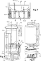
figures 7 et 8 représentent respectivement une première et une deuxième configurations de mise en place de l'échangeur de chaleur du deuxième mode de réalisation du dispositif combiné selon lafigure 3 , l'échangeur de chaleur étant disposé sous le ballon de stockage dans la première configuration et autour du ballon de stockage dans la deuxième configuration. - La
figure 9 représente schématiquement une vue éclatée du deuxième mode de réalisation du dispositif combiné selon lafigure 3 dans une configuration modulaire. - Les
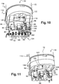
figures 10 et 11 représentent schématiquement une vue détaillée de la partie inférieure du dispositif combiné avec et sans platine de raccordement, respectivement. - La
figure 12 représente schématiquement une vue en perspective de la platine de raccordement selon lafigure 9 . - La
figure 13 représente schématiquement une vue détaillée de la partie inférieure du deuxième mode de réalisation du dispositif combiné selon lafigure 3 comprenant un kit de chauffage multizone.
- The
figure 1 shows a hydraulic diagram of a combined device for heating domestic water and water for heating a room known from the prior art. - The
figure 2 shows a hydraulic diagram of a first embodiment of a combined device for heating domestic water and space heating water according to the invention. - The
figure 3 shows a hydraulic diagram of a second embodiment of a combined device for heating domestic water and space heating water according to the invention. - The
figure 4 shows a partial cross-sectional view of a heat exchanger of the second embodiment of the combined device according to thefigure 3 . - The
Figures 5 and 6 respectively represent a perspective view and a partial sectional view of the heat exchanger of the second embodiment of the combined device according to thefigure 3 . - The
Figures 7 and 8 represent respectively a first and a second configuration of installation of the heat exchanger of the second embodiment of the combined device according to thefigure 3 , the heat exchanger being arranged under the storage tank in the first configuration and around the storage tank in the second configuration. - The
figure 9 shows schematically an exploded view of the second embodiment of the combined device according to thefigure 3 in a modular configuration. - The
figures 10 and 11 schematically represent a detailed view of the lower part of the device combined with and without connection plate, respectively. - The
figure 12 schematically represents a perspective view of the connection plate according to thefigure 9 . - The
figure 13 schematically represents a detailed view of the lower part of the second embodiment of the combined device according to thefigure 3 including a multi-zone heating kit.
Il est proposé un dispositif combiné de chauffage de l'eau sanitaire et de l'eau de chauffage d'un local. Ce dispositif combiné comprend un ou plusieurs échangeur de chaleur pour transférer de la chaleur simultanément entre un fluide caloporteur et de l'eau de chauffage présente dans le circuit d'eau de chauffage et entre ce fluide caloporteur et de l'eau sanitaire présente dans le circuit d'eau sanitaire. Un premier mode de réalisation du dispositif combiné est représenté en
Ces deux modes de réalisation doivent être considérés comme des exemples de réalisation du dispositif combiné selon l'invention et non comme les seules configurations possibles pour le dispositif combiné. Les pièces et ensembles communs aux premier et deuxième modes de réalisation portent les mêmes références.These two embodiments should be considered as exemplary embodiments of the combined device according to the invention and not as the only possible configurations for the combined device. The parts and assemblies common to the first and second embodiments have the same references.
Selon la
L'unité extérieure 60, le circuit de fluide caloporteur 62 et le premier échangeur 41 de chaleur forment une pompe à chaleur apte à réguler la température de l'eau de chauffage présente dans le circuit d'eau de chauffage 56.The
Le dispositif combiné 40 comprend également un ballon de stockage 52 d'eau sanitaire et un circuit d'eau sanitaire 54 pour fournir de l'eau sanitaire à au moins un organe de distribution d'eau sanitaire (non représenté).The combined
Le circuit d'eau sanitaire 54 comprend un circuit de distribution d'eau sanitaire 82 en communication de fluide avec le ballon de stockage 52 et destiné à être raccordé audit au moins un organe de distribution d'eau sanitaire.The
Pour le chauffage de l'eau sanitaire, le circuit d'eau sanitaire 54 comprend en outre un circuit de chauffage de l'eau sanitaire 80. Le dispositif combiné 40 comprend un deuxième échangeur de chaleur 42 apte à échanger de la chaleur entre un circuit de fluide caloporteur 62 et le circuit de chauffage de l'eau sanitaire 80. En particulier, le circuit de chauffage de l'eau sanitaire 80 est raccordé au ballon de stockage 52. Un deuxième circulateur 44 permet la circulation de fluide à l'intérieur du circuit de chauffage de l'eau sanitaire 80.For heating domestic water, the
Le premier mode de réalisation du dispositif combiné comprend donc deux échangeurs de chaleur ainsi que deux circuits distincts de chauffage de l'eau sanitaire et de l'eau de chauffage. Le circuit de chauffage de l'eau de chauffage est confondu avec le circuit d'eau de chauffage 56. En particulier, les circuits d'eau de chauffage 56 et de chauffage de l'eau sanitaire 80 ne comprennent aucune portion de conduite commune. Ainsi, une chauffe simultanée de l'eau de chauffage et de l'eau sanitaire peut être réalisée. Ceci est particulièrement avantageux sur le plan du confort de l'utilisateur et de la consommation énergétique en comparaison au dispositif combiné 10 de l'art antérieur représenté en
Tel que représenté sur la
De manière alternative, le circuit de chauffage de l'eau sanitaire 80 peut être dépourvu de troisième échangeur 43. Dans ce cas, le circuit de chauffage de l'eau sanitaire 80 est en communication de fluide avec le circuit de distribution d'eau sanitaire 82. En d'autres termes, le circuit de chauffage de l'eau sanitaire 80 forme une boucle ouverte débouchant à l'intérieur du ballon de stockage 52. Le fluide circulant à l'intérieur du circuit de chauffage d'eau sanitaire 80 est donc de l'eau sanitaire. En particulier, le fluide circulant à l'intérieur du circuit de chauffage d'eau sanitaire 80 est l'eau sanitaire distribuée audit au moins organe de distribution. La température de l'eau sanitaire distribuée est donc ici régulée par échange de chaleur direct avec le circuit de fluide caloporteur 62 via le deuxième échangeur 42. Dans cette configuration de boucle ouverte, le ballon de stockage 52 est de préférence un ballon à canules tel que représenté en
Ce mode alternatif dans lequel le ballon de stockage 52 est dépourvu de troisième échangeur 43 permet d'augmenter le volume disponible à l'intérieur du ballon de stockage 52 ou, plus avantageusement, d'en réduire son encombrement extérieur pour un même volume disponible. En effet, la présence d'un échangeur de chaleur, notamment à serpentin, à l'intérieur du ballon de stockage 52 diminue le volume intérieur disponible. Ceci impose un surdimensionnement du ballon de stockage 52 pour un volume d'eau sanitaire maximum souhaité à l'intérieur du ballon de stockage 52. Ainsi, l'absence d'échangeur à l'intérieur du ballon de stockage 52 permet de réduire le nombre et le volume des composants du dispositif combiné, et donc sa masse, par rapport au dispositif combiné 10 de la
De plus, une partie du gain de masse est lié au type d'échangeur en lui-même. En effet, un échangeur de chaleur à serpentin est beaucoup plus volumineux/lourd qu'un échangeur de chaleur externe au ballon de stockage 52. Avec un échangeur de chaleur de type serpentin, l'eau du ballon de stockage 52 est réchauffée par convection naturelle. Il faut donc un échangeur très grand pour avoir des performances acceptables. A contrario, l'eau est réchauffée par convection forcée avec un échangeur de chaleur externe ce qui augmente de manière importante la performance de l'échange.In addition, part of the mass gain is linked to the type of exchanger itself. Indeed, a coil heat exchanger is much larger / heavier than a heat exchanger external to the
Cet encombrement important du dispositif combiné 10 ainsi que sa masse importante, dû notamment au surdimensionnement du ballon de stockage 14, nécessitent une installation du dispositif combiné 10 sur le sol. En effet, il a été observé que pour des raisons de reprise d'efforts et de simplicité de mise en place, il n'est pas envisageable de suspendre le dispositif combiné 10 au-dessus du sol comme peut l'être une chaudière murale. En effet, le dispositif combiné 10 pèse environ 140kg lorsqu'il est vide d'eau et environ 350kg lorsqu'il est rempli d'eau. De plus, le dispositif combiné 10 mesure environ 1.80m de hauteur ce qui limite son positionnement. Le dispositif combiné 10 est dit « sur socle » lorsqu'il est configuré pour être disposé sur le sol, i.e. non suspendu à un support au-dessus du sol. L'absence d'échangeur de chaleur à l'intérieur du ballon de stockage 52 permet d'envisager de la suspendre à un support, notamment à mur, au-dessus du sol.This large size of the combined
Selon la
Pour le chauffage de l'eau de chauffage et de l'eau sanitaire, le dispositif combiné 50 comprend également un échangeur de chaleur 58 dans lequel un fluide caloporteur est apte à circuler via un circuit de fluide caloporteur 62. Le dispositif combiné 50 est de préférence couplé à une unité extérieure 60 disposée à l'extérieur du local. L'échangeur de chaleur 58, le circuit de fluide caloporteur 62 et l'unité extérieure 60 forment une pompe à chaleur. L'échangeur de chaleur 58 est configuré pour effectuer un échange de chaleur entre le fluide caloporteur et de l'eau sanitaire présente dans le circuit d'eau sanitaire, et entre le fluide caloporteur et de l'eau de chauffage présente dans le circuit d'eau de chauffage. En d'autres termes, l'échangeur de chaleur 58 est configuré pour recevoir trois fluides et transmettre de la chaleur à deux de ces fluides via le fluide caloporteur. L'échangeur de chaleur 58 correspond ainsi à un échangeur de chaleur à trois voies ce qui permet de réaliser un échange de chaleur direct entre le fluide caloporteur et l'eau de chauffage, mais également un échange de chaleur direct entre le fluide caloporteur et l'eau sanitaire.For heating the heating water and the domestic water, the combined
De plus, les circuits de chauffage de l'eau sanitaire et de chauffage de l'eau de chauffage sont agencés de manière distincte pour permettre la dissociation entre le chauffage de l'eau sanitaire et le chauffage de l'eau de chauffage. Le circuit de chauffage de l'eau sanitaire correspond à une portion du circuit d'eau sanitaire 54 mettant en communication de fluide le ballon de stockage 52 avec l'échangeur de chaleur 58. Le circuit de chauffage de l'eau de chauffage est confondu avec le circuit d'eau de chauffage 56. De préférence, les circuits de chauffage de l'eau sanitaire et de chauffage de l'eau de chauffage ne comprennent aucune portion de conduite commune. Cet agencement de chauffage distinct permet au dispositif combiné 50 d'avoir une boucle dédiée au chauffage de de l'eau sanitaire. Ainsi, il est possible de réaliser une chauffe simultanée de l'eau de chauffage et de l'eau sanitaire. Les stratégies de chauffage de l'eau sanitaire sont ainsi plus flexibles. Une optimisation plus importante peut donc être réalisée. Ceci est particulièrement avantageux sur le plan du confort de l'utilisateur et de la consommation énergétique en comparaison au dispositif combiné 10 de l'art antérieur représenté en
De plus, cette configuration indépendante des circuits de chauffage de l'eau permet d'utiliser l'eau sanitaire du circuit de chauffage de l'eau sanitaire pour le dégivrage de l'unité extérieur 60. En effet, lorsqu'il fait froid et humide, l'unité extérieur 60 de la pompe à chaleur peut prendre en glace. Ceci est phénomène normal et prévu dans le fonctionnement de l'unité extérieure 60. Pour dégivrer cette unité extérieure 60, il généralement prévu d'inverser le fonctionnement de la pompe à chaleur, i.e. la pompe à chaleur prélève de la chaleur à l'intérieur du local pour réchauffer l'unité extérieure 60. Ce phénomène relativement court, généralement inférieur à 15min, peut engendrer un inconfort côté utilisateur, d'une part, et peut également entraîner dans certaines conditions un risque de prise en glace du circuit d'eau de chauffage 56 au niveau de son interface avec le fluide caloporteur. Cette interface se situe au niveau de l'échangeur de chaleur 58 dans le mode de réalisation de la
Tel représenté en
Une paroi d'échange 76 de chaleur est disposée entre la première 70 et la deuxième 72 zones d'échange ainsi qu'entre la deuxième 72 et la troisième 74 zones d'échange. Ces parois d'échanges 76 correspondent aux parois des première 64 et deuxième 66 conduites. Ces parois d'échange 76 permettent la transmission de la chaleur entre les deux fluides présents de part et d'autre de la paroi déchange 76.A
Selon une configuration préférée de l'échangeur de chaleur 58, la première zone d'écoulement 70 est formée à l'intérieur de la première conduite 64. La deuxième zone d'écoulement 72 est formée entre les première 64 et deuxième 66 conduites. La troisième zone d'écoulement 74 est formée entre les deuxième 66 et troisième 68 conduites.According to a preferred configuration of the
Selon une configuration encore préférée, la deuxième zone d'écoulement 72 est configurée pour transporter le fluide caloporteur du circuit de fluide caloporteur 62. De plus, chacune des première 70 et troisième 74 zones d'écoulement est configurée pour transporter l'un parmi l'eau sanitaire et l'eau de chauffage. Pour des questions réglementaires, la conduite séparant la deuxième zone d'écoulement 72 de la zone d'écoulement transportant l'eau sanitaire comporte de préférence une double paroi. Ainsi, l'eau sanitaire est davantage protégée d'une éventuelle contamination. De manière préférée, la première zone d'écoulement 70 est configurée pour transporter l'eau sanitaire. Dans cette configuration, la première conduite 64 est de préférence réalisée en cuivre. En particulier, cette première conduite 64 est de préférence un tube en cuivre dont les surfaces interne et externe sont lisses de manière à être très robustes vis-à-vis de l'entartrage.According to a more preferred configuration, the
Pour optimiser le positionnement et l'encombrement de l'échangeur de chaleur 58, la trajectoire ou profil A est de préférence hélicoïdale, telle que représentée sur la
Telles qu'illustrées à la
Tel que visible sur la
Le circuit de chauffage d'eau sanitaire 80 comprend une première conduite de départ 84 reliant le ballon de stockage 52 à une entrée d'eau sanitaire de l'échangeur de chaleur 58 et une première conduite de retour 86 reliant une sortie d'eau sanitaire de l'échangeur de chaleur 58 au ballon de stockage 52. En particulier, la première conduite de départ 84 et la première conduite de retour 86 sont chacune raccordées à une extrémité de la première zone d'écoulement 70 de l'échangeur de chaleur 58 via les raccords d'échangeur 78. Pour la mise en circulation de l'eau sanitaire à l'intérieur du circuit de chauffage d'eau sanitaire 80, ce dernier comprend également un premier circulateur 88. Le circuit de chauffage d'eau sanitaire 80 forme un circuit de chauffage de l'eau sanitaire.The domestic
Le dispositif combiné 50 comprend en outre un contrôleur 87 configuré pour réguler la vitesse du premier circulateur 88 de manière à réguler le débit de l'eau sanitaire circulant dans le circuit de chauffage d'eau sanitaire 80. Le contrôleur 87 est également configuré pour réguler le débit du fluide caloporteur. La régulation simultanée ou sélective du débit de circulation de l'eau sanitaire et du fluide caloporteur permet de réguler la température de l'eau sanitaire fournie au ballon de stockage 52. Un tel contrôleur 87 peut également être utilisé dans le dispositif combiné 40 du premier mode de réalisation pour réguler le débit du fluide caloporteur et la vitesse du deuxième circulateur 44. Le contrôleur 87 permet d'optimiser la performance pendant la chauffe ou de garantir la tenue dans le temps de l'échangeur (par exemple, en évitant le risque de prise en glace).The combined
Le circuit de distribution d'eau sanitaire 82 comprend une deuxième conduite de départ 90 reliant le ballon de stockage 52 à un raccord de départ d'eau sanitaire 92. Cette deuxième conduite de départ 90 peut être autrement considérée comme une conduite de départ d'eau chaude hors du ballon vers une installation d'eau sanitaire (non représentée). Cette installation d'eau sanitaire comporte notamment les organes de distribution d'eau sanitaire mentionnés ci-avant. Le circuit de distribution d'eau sanitaire 82 comprend également une deuxième conduite de retour 94 reliée à un raccord de retour d'eau sanitaire 96. La deuxième conduite de retour 94 met en communication de fluide le ballon de stockage 52 avec ce raccord de retour d'eau sanitaire 96. Cette deuxième conduite de départ 90 peut être autrement considérée comme une conduite de retour d'eau froide provenant d'une source d'eau sanitaire de l'installation d'eau sanitaire. Cette eau froide correspond de préférence à l'eau fournie par le réseau de distribution d'eau courante de la localité. La température de cette eau est généralement comprise entre 5 à 25°C au niveau du dispositif combiné 50.The sanitary
Pour limiter le nombre de raccordements du circuit d'eau sanitaire 54 avec le ballon de stockage 52, la deuxième conduite de retour 94 est raccordée à la première conduite de départ 84 au moyen d'un raccord en Té 98. En d'autres termes, la deuxième conduite de retour 94 est raccordée indirectement au ballon de stockage 52 via la première conduite de départ 84. On entend par « raccord en Té », une portion de conduite ayant trois orifices en communication de fluides les uns avec les autres. Ainsi, le raccord en Té 98 comprend un premier orifice en communication de fluide avec le ballon de stockage 52, un deuxième orifice en communication de fluide avec l'échangeur de chaleur 58 et un troisième orifice en communication de fluide avec la deuxième conduite de retour 94.To limit the number of connections of the
Lorsque le dispositif combiné 50 est configuré pour être suspendu au-dessus du sol, la deuxième conduite de départ 90, la première conduite de retour 86 et la portion de conduite entre le ballon de stockage 52 et le raccord en Té 98 sont raccordées au ballon de stockage 52 de préférence dans une partie inférieure du ballon de stockage 52. Une telle disposition est par exemple visible sur les
Le circuit d'eau de chauffage 56 comprend une conduite de retour d'eau de chauffage 100 reliant un raccord de retour d'eau de chauffage 102 à une entrée de l'échangeur de chaleur 58. Le circuit d'eau de chauffage 56 comprend également une conduite de départ d'eau de chauffage 104 reliant un raccord de départ d'eau de chauffage 106 à une sortie de l'échangeur de chaleur 58. En particulier, la conduite de retour d'eau de chauffage 100 et la conduite de départ d'eau de chauffage 104 sont chacune raccordées à une extrémité de la troisième zone d'écoulement 74 de l'échangeur de chaleur 58 via les raccords d'échangeur 78. Pour la mise en circulation de l'eau de chauffage à l'intérieur du circuit d'eau de chauffage 56 lorsque celui-ci est raccordé à une installation de chauffage du local, le circuit d'eau de chauffage 56 comprend également un deuxième circulateur 108.The
Le contrôleur 87 est en outre configuré pour réguler la vitesse du deuxième circulateur 108 de manière à réguler le débit de l'eau de chauffage circulant dans le circuit d'eau de chauffage 56. La régulation simultanée ou sélective du débit de circulation de l'eau de chauffage et du fluide caloporteur permet de réguler la température de l'eau de chauffage fournie à l'installation de chauffage. Un tel contrôleur 87 peut également être utilisé dans le dispositif combiné 40 du premier mode de réalisation pour réguler le débit du fluide caloporteur et la vitesse du premier circulateur 46.The
Lors de la mise en service du dispositif combiné 50, l'installation d'eau sanitaire est reliée au dispositif combiné 50 par le biais des raccords de départ 92 et de retour 96 d'eau sanitaire. De manière similaire, l'installation de chauffage du local est reliée au dispositif combiné 50 par le biais des raccords de départ 106 et de retour 102 d'eau de chauffage.When the combined
Le ballon de stockage 52 est de préférence un ballon à canules. En d'autres termes, le ballon de stockage 52 est raccordé aux premier 80 et deuxième 82 circuits d'eau sanitaire par le biais de canules disposées à l'intérieur du ballon de stockage 52. L'utilisation de canules permet notamment de disposer les orifices d'entrée ou de sorties des premier 80 et deuxième 82 circuits d'eau sanitaire à des position prédéterminées à l'intérieur du ballon de stockage 52. Ainsi, il est possible de limiter le brassage de l'eau sanitaire à l'intérieur du ballon de stockage 52 en définissant les positions adéquates où l'eau sanitaire est aspirée et refoulée tant pour son chauffage que pour sa distribution. Une « stratification en température » de l'eau sanitaire est rendue possible à l'intérieur du ballon de stockage 52. On entend par stratification en température, le fait qu'un gradient de température important peut être maintenu dans le ballon de stockage 52. On peut ainsi schématiser la stratification obtenue en indiquant que la partie inférieure du ballon de stockage comporte de l'eau froide, la partie médiane de l'eau tiède et la partie supérieure de l'eau chaude.The
Chacun des premier 80 et deuxième 82 circuits d'eau sanitaire est en communication de fluide avec le ballon de stockage 52 au niveau d'un orifice d'aspiration (ou d'entrée) et d'un orifice de refoulement (ou de sortie) de l'eau sanitaire formés chacun au niveau d'un canule disposée à l'intérieur du ballon de stockage 52. La position des orifices d'aspiration (ou d'entrée) et d'un orifice de refoulement (ou de sortie) de l'eau sanitaire à l'intérieur du ballon de stockage est définie pour limiter le brassage de l'eau sanitaire. Cette position est notamment définie par rapport à la hauteur de stockage à l'intérieur du ballon de stockage 52.Each of the first 80 and second 82 domestic water circuits is in fluid communication with the
On définit la hauteur de stockage comme la distance séparant le point le plus bas et le point de la plus haut de la cavité intérieure du ballon de stockage 52 le long d'un axe vertical. Le point le plus bas de la cavité intérieure correspond donc à 0% de la hauteur de stockage. Inversement, le point le plus haut de la cavité intérieure correspond à 100% de la hauteur de stockage.The storage height is defined as the distance between the lowest point and the highest point of the interior cavity of the
L'orifice d'aspiration du premier circuit d'eau sanitaire 80 est disposé en partie inférieure du ballon de stockage 52, i.e. au niveau d'une zone du ballon de stockage 52 où l'eau est à basse température. L'orifice d'aspiration du premier circuit d'eau sanitaire 80 est ainsi disposé de préférence entre 0 et 20% de la hauteur de stockage du ballon de stockage. De manière encore préférée, l'orifice d'aspiration du premier circuit d'eau sanitaire 80 est disposé de préférence entre 0 et 10% de la hauteur de stockage. L'eau sanitaire est ainsi aspirée le plus bas possible à l'intérieur du ballon de stockage 52. Ceci permet d'aspirer l'eau au niveau d'une position optimum permettant d'aspirer l'eau sanitaire à une température la plus basse possible tout en limitant de brasser l'eau à l'intérieur du ballon de stockage 52.The suction port of the first
L'orifice de refoulement du premier circuit d'eau sanitaire 80 est lui disposé en partie médiane du ballon de stockage 52. L'orifice de refoulement du premier circuit d'eau sanitaire 80 est de préférence disposé entre 20% et 80% de la hauteur de stockage, de manière encore préférée entre 30% et 70% de la hauteur de stockage. De manière encore préférée, l'orifice de refoulement du premier circuit d'eau sanitaire 80 est disposé à 50% de la hauteur de stockage. Le fait de refouler l'eau sanitaire chauffée au niveau d'une position médiane permet de limiter le brassage à l'intérieur du ballon de stockage 52. Cette position médiane de l'orifice de refoulement du premier circuit d'eau sanitaire 80 permet d'obtenir un compromis optimum entre performance et confort de l'utilisateur. En effet, un positionnement trop proche de la partie supérieure du ballon de stockage 52 entrainerait un brassage de cette partie supérieure. Ce brassage est néfaste car il ne permet pas de conserver une réserve d'eau chaude au cas où un puisage inopiné surviendrait. De plus, un positionnement trop proche de la partie inférieure du ballon de stockage 52 et donc de la canule d'aspiration du premier circuit d'eau sanitaire 80 entrainerait une baisse de performance.The delivery port of the first
L'orifice d'aspiration du deuxième circuit d'eau sanitaire 82 est disposé en partie supérieure du ballon de stockage 52. L'orifice d'aspiration du circuit de distribution d'eau sanitaire 82 est disposé de préférence entre 80% et 100% de la hauteur de stockage, de manière encore préférée entre 90% et 100% de la hauteur de stockage. Ainsi, l'eau chaude est aspirée en partie haute du ballon de stockage 52.The suction port of the second
L'orifice de refoulement du circuit de distribution d'eau sanitaire 82 est disposé en partie inférieure du ballon de stockage 52. L'orifice de refoulement du circuit de distribution d'eau sanitaire 82 est disposé de préférence entre 0 et 20% de la hauteur de stockage, de manière préférée entre 0% et 10% de la hauteur de stockage.The discharge orifice of the sanitary
Chaque canule comporte une extrémité proximale solidaire d'une paroi du ballon de stockage 52 et une extrémité distale libre où sont formés les orifices d'aspiration et de refoulement des premier 80 et deuxième 82 circuits d'eau sanitaire. L'extrémité proximale est de préférence solidaire de la paroi formant le fond du ballon de stockage 52 de manière à rendre accessibles les canules sous le ballon de stockage 52. Cet accès sous le ballon de stockage 52 permet de connecter aisément le ballon de stockage 52 aux premier 80 et deuxième 82 circuits d'eau sanitaire lors du montage du dispositif combiné.Each cannula has a proximal end secured to a wall of the
Le positionnement des orifices d'aspiration et de refoulement est donc obtenu en positionnant l'extrémité distale de chacune des canules. Les orifices d'aspiration ou de refoulement peuvent être formés par une ou plusieurs canules. En d'autres termes, une canule peut comporter un ou plusieurs des orifices d'aspiration et de refoulement. Selon un mode de réalisation préféré et détaillé ci-après, les orifices d'aspiration du premier circuit d'eau sanitaire 80 et de refoulement du deuxième circuit d'eau sanitaire 82 sont formés sur une même canule 118. En particulier, ces orifices d'aspiration du premier circuit d'eau sanitaire 80 et de refoulement du deuxième circuit d'eau sanitaire 82 sont confondus. Le dispositif combiné peut ainsi comporter trois ou quatre canules. Dans ce premier cas, une canule réalise conjointement une fonction d'aspiration de l'eau sanitaire en direction du premier circuit d'eau sanitaire et de refoulement de l'eau sanitaire en provenance du deuxième circuit d'eau sanitaire.The positioning of the suction and delivery ports is therefore obtained by positioning the distal end of each of the cannulas. The suction or delivery ports can be formed by one or more cannulas. In other words, a cannula may have one or more of the suction and delivery ports. According to a preferred and detailed embodiment below, the suction orifices of the first
Lorsque les orifices d'aspiration du premier circuit d'eau sanitaire 80 et de refoulement du deuxième circuit d'eau sanitaire 82 sont formés sur une même canule 118, la canule 118 est réalisée de préférence de sorte que les pertes de charges à l'intérieur de cette canule 118 sont inférieurs aux pertes de charges à l'intérieur du premier circuit d'eau sanitaire 80. Ainsi, cette différence de pertes de charge permet d'éviter que l'eau sanitaire provenant de la première conduite de départ 84 ne rentre à l'intérieur du ballon de stockage 52 par le biais de la canule de refoulement 122. Ceci viendrait empêcher la stratification des couches de fluide à l'intérieur du ballon de stockage 52 et donc réduire les performances de l'installation.When the suction ports of the first
Chaque canule au niveau de laquelle un orifice de refoulement est disposé ou formé est configurée pour refouler l'eau sanitaire à l'intérieur du ballon de stockage 52 le long d'une direction transversale à un axe vertical pour réduire le brassage de l'eau sanitaire. Ceci est réalisé par un brise-jet formé sur la canule en obstruant son extrémité distale et en formant un ou plusieurs orifices latéraux sur une paroi périphérique de la canule.Each cannula at which a delivery port is disposed or formed is configured to deliver sanitary water to the interior of the
Dans le cas d'un ballon à canules, le ballon de stockage 52 ne contient donc aucun échangeur de chaleur, notamment pas d'échangeur de chaleur de type serpentin. Le volume disponible à l'intérieur du ballon de stockage 52 est ainsi plus important que dans le cas d'un ballon à serpentin pour un même volume extérieur du ballon de stockage 52. En effet, le volume « mort » ou indisponible se trouvant à l'emplacement du serpentin et en-dessous de celui-ci n'est pas présent ici. Ainsi, le ballon de stockage 52 présente de préférence un volume intérieur inférieur ou égal à 150 dm3, de préférence inférieur ou égal à 100 dm3. En comparaison, le dispositif combiné 10 de l'art antérieur est généralement utilisé avec un ballon de stockage 12 ayant un volume intérieur, avant mise en place du serpentin, de 190 dm3. Ceci permet au dispositif combiné 52 d'être plus compact et d'avoir un prix de fabrication inférieur au dispositif combiné 10 de l'art antérieur.In the case of a cannulated balloon, the
Cette configuration comprenant un ballon de stockage 52 à canules permet au dispositif combiné 52 d'avoir une hauteur maximale le long d'un axe longitudinal d'extension C du ballon de stockage 52 inférieure ou égale à 150 cm, de préférence inférieure ou égale à 145 cm.This configuration comprising a
Tel que représenté sur la
La canule combinée 118 est configurée pour être raccordée à la première conduite de départ 84. La deuxième conduite de retour 94 est raccordée à la première conduite de départ 84 au moyen d'un raccord en Té de sorte que le refoulement dans le ballon de stockage 52 de l'eau sanitaire provenant de la deuxième conduite de retour 94 est réalisé au travers de la canule combinée 118. La canule combinée 118 s'étend à l'intérieur du ballon de stockage 52 de sorte que son orifice d'extrémité débouche au niveau d'une partie inférieure du ballon de stockage 52. Ainsi, la canule combinée 118 est configurée pour fonctionner soit en aspiration soit en refoulement selon le mode de fonctionnement du circuit d'eau sanitaire 54. En effet, la canule d'aspiration 118 est configurée pour aspirer de l'eau froide en partie basse du ballon de stockage 52 lors d'une phase de chauffage de l'eau sanitaire, i.e. lorsqu'il y a circulation de l'eau sanitaire à l'intérieur du premier circuit d'eau sanitaire 80. A contrario, la canule d'aspiration 118 est configurée pour refouler de l'eau sanitaire à l'intérieur du ballon de stockage 52 lors d'un soutirage d'eau sanitaire via la deuxième canule d'aspiration 120, i.e. lorsqu'il y a circulation de l'eau sanitaire à l'intérieur du deuxième circuit d'eau sanitaire 82.The combined
De plus, la canule combinée 118 comporte de préférence un brise-jet pour permettre l'aspiration ou le refoulement de l'eau sanitaire dans une direction transversale à l'axe longitudinal d'extension C du ballon de stockage 52. Le brise-jet peut être formé sur la canule combinée 118 en obstruant son extrémité distale et en formant un ou plusieurs orifices latéraux sur une paroi périphérique de la canule combinée 118. Ceci permet de réduire le brassage provoqué par le refoulement de l'eau sanitaire provenant de la deuxième conduite de retour 94 lorsque celui-ci est réalisé le long de l'axe longitudinal d'extension C du ballon de stockage 52. La canule de refoulement 122 comporte également de préférence un brise-jet au niveau de son extrémité distale, i.e. l'extrémité où l'eau est refoulée à l'intérieur du ballon de stockage 52.In addition, the combined
De manière alternative, le dispositif combiné 50 peut être dépourvu de raccord en Té de sorte que chacune des première conduite de départ 84 et deuxième conduite de retour 94 débouchent distinctement à l'intérieur du ballon de stockage 52. Dans ce mode de réalisation alternatif, la canule combinée 118 fonctionne uniquement comme une canule d'aspiration et une canule supplémentaire de refoulement est disposée à l'extrémité de la deuxième conduite de retour 94.Alternatively, the combined
La canule d'aspiration 120 est configurée pour être raccordée à la deuxième conduite de départ 90. La canule d'aspiration 120 s'étend à l'intérieur du ballon de stockage 52 de sorte que son orifice d'extrémité débouche au niveau d'une partie supérieure du ballon de stockage 52. Ainsi, la canule d'aspiration 122 est configurée pour aspirer de l'eau chaude en partie haute du ballon de stockage 52.The
La canule de refoulement 122 est configurée pour être raccordée à la première conduite de retour 86. Pour obtenir un bon compromis entre performance et confort de l'utilisateur, l'extrémité distale de la canule de refoulement 122 est située à une position intermédiaire ou médiane de la hauteur de la cavité interne du ballon de stockage 52. En effet, un positionnement trop proche de la partie supérieure du ballon de stockage 52 entrainerait un brassage de cette partie supérieure. Ce brassage est néfaste car il ne permet pas de conserver une réserve d'eau chaude au cas où un puisage inopiné surviendrait. De plus, un positionnement trop proche de la partie inférieure du ballon de stockage 52, et donc de la canule combinée 118, entrainerait une baisse de performance.The
En particulier, l'extrémité distale de la canule de refoulement 122 est située à une position distante de la paroi supérieure du ballon de stockage 52 d'au moins 20% de la hauteur de la cavité interne du ballon de stockage 52 et distante de la paroi inférieure du ballon de stockage 52 d'au moins 20% de la hauteur de la cavité interne du ballon de stockage 52. En d'autres termes, l'extrémité distale de la canule de refoulement 122 est située entre 20% et 80% de la hauteur de la cavité interne du ballon de stockage 52. De manière alternative, l'extrémité distale de la canule de refoulement 122 peut être située entre 30% et 70% de la hauteur de la cavité interne du ballon de stockage 52.In particular, the distal end of the
Pour obtenir un compromis optimum entre performance et confort de l'utilisateur, l'extrémité distale de la canule de refoulement 122 est de préférence située à environ 50% de la hauteur de la cavité interne du ballon de stockage 52.To obtain an optimum compromise between performance and user comfort, the distal end of the
Grâce au ballon de stockage 52 à canules l'eau sanitaire est prélevée en partie basse du ballon de stockage 52 pour être réchauffée dans l'échangeur de chaleur 58, i.e. la partie du ballon de stockage 52 où l'eau froide est refoulée par la deuxième conduite de retour 94. En conséquence, même si le ballon n'est pas entièrement froid, les performances ne seront pas pour autant dégradées. Ainsi, des chauffes performantes peuvent être réalisées sans pour autant risquer une situation d'inconfort pour l'utilisateur. Ceci est dû au fait que l'on peut, si besoin, alimenter le circuit d'eau de chauffage 56 sans pour autant couper le chauffage de l'eau sanitaire. On peut donc faire des chauffes optimisées sans être contraint par le circuit d'eau de chauffage 56. Si un soutirage par les organes de distribution survient lors de la chauffe de l'eau sanitaire, la température de l'eau sanitaire réduit immédiatement en entrée de l'échangeur de chaleur 58 ce qui réduit la température de condensation à l'intérieur du ballon de stockage 52. Le coefficient de performance de la pompe à chaleur est donc amélioré. En définitive, ce soutirage aura un impact très faible sur la performance moyenne de la chauffe de l'eau sanitaire. Les phases de chauffage de l'eau sanitaire peuvent ainsi être plus longues que dans le cas d'un ballon à serpentin pour une meilleure performance.Thanks to the
Tel qu'illustré sur les
Les moyens de fixation comportent de préférence une structure d'interface entre le support 112 et des modules formés par le dispositif combiné 50. Cette structure d'interface est par exemple un cadre ou une échelle fixé(e) au mur ou au support 112 sur lequel ou laquelle le dispositif combiné 50 est suspendu. Cette structure interface permet la répartition des efforts sur le support 112 pour faciliter et pérenniser l'installation du dispositif combiné 50. En effet, un mur peut être non-porteur et donc peu adapté à supporter de fortes charges suspendues. A titre de référence, le dispositif combiné 50, une fois rempli d'eau, pèse plus de 200kg.The fixing means preferably comprise an interface structure between the
Selon une configuration préférée du dispositif combiné 50, l'échangeur de chaleur 58 est disposé au-dessous du ballon de stockage 52, tel qu'illustré sur la
Les dimensions externes de l'échangeur de chaleur 58 sont de préférence inférieures ou égales aux dimensions externes du ballon de stockage 52. Ainsi, l'encombrement transversal du dispositif combiné 50 est sensiblement constant le long de l'axe longitudinal d'extension C. De manière alternative, les dimensions externes de l'échangeur de chaleur 58 peuvent être supérieures aux dimensions externes du ballon de stockage 52.The external dimensions of the
La
Dans ces deux configurations de l'échangeur de chaleur 58, en-dessous ou autour du ballon de stockage 52, l'échangeur de chaleur 58 et le ballon de stockage 52 sont de préférence concentriques. En d'autres termes, l'axe longitudinal B de l'échangeur de chaleur 58 est confondu avec l'axe d'extension longitudinal C du ballon de stockage 52.In these two configurations of the
De plus, le dispositif combiné 50 comprend une platine de raccordement 124 du circuit d'eau de chauffage 56 à une installation d'eau de chauffage du local et du circuit d'eau sanitaire 54 à une installation d'eau sanitaire du local. Un telle platine de raccordement 124 est visible sur les
Une telle platine de raccordement 124 peut également être utilisée dans le dispositif combiné 40 du premier mode de réalisation et être raccordée au circuit d'eau de chauffage 56 et au circuit d'eau sanitaire 54.Such a
De plus, le regroupement des raccords sur la platine de raccordement 124 permet l'utilisation de beaucoup de composants déjà utilisés pour les chaudières murales ce qui permet de réduire le coût de fabrication du dispositif combiné 50.In addition, the grouping of the fittings on the
La platine de raccordement 124 est de préférence disposée en-dessous du ballon de stockage 52 pour en améliorer son accessibilité, notamment à un installateur. La platine de raccordement 124 est de préférence disposée à l'arrière du dispositif combiné 52. Cette position en arrière de la platine de raccordement 124 permet de pouvoir la fixer à un support. La platine de raccordement 124 peut être disposée au niveau et/ou sous les moyens de fixation 110.The
Le platine de raccordement 124 est de préférence formée par une plaque allongée comportant une pluralité d'orifices aptes à recevoir une pluralité de raccords. La platine de raccordement 124 peut également comporter des moyens de fixation dédiés 126 pour permettre la fixation de la platine de raccordement au support 112 ou à tout autre support.The
Tel que représenté sur les
Ce groupe de sécurité permet de réguler la pression à l'intérieur du ballon de stockage 52. Selon la réglementation en vigueur (NF DTU 60 - Plomberie), un groupe de sécurité doit être installé sur l'arrivée d'eau froide (ou conduite de retour d'eau sanitaire) d'un ballon de stockage d'eau sanitaire. Le groupe de sécurité implique une mise en place souvent laborieuse et peut être très encombrant en sus du volume occupé par le dispositif combiné 50. La simplification de son installation est donc un bénéfice important pour son installateur. La mise en place de ce groupe de sécurité est ici simplifiée par la présence du raccord de sécurité 129 permettant le montage d'un groupe de sécurité 128 selon les besoins de l'utilisateur.This safety group is used to regulate the pressure inside the
Le dispositif combiné 40 du premier mode de réalisation peut également comprendre un raccord de sécurité 128 de manière à être raccordé à un groupe de sécurité.The combined
Le dispositif combiné 50 peut être configuré pour être raccordé à un kit de chauffage multizone permettant de raccorder le dispositif combiné 50 à plusieurs installations d'eau de chauffage. Un tel kit de chauffage multizone 136 est représenté sur la
Le dispositif combiné 50 peut également comprendre un disconnecteur 140 pour remplir le circuit d'eau de chauffage 56 avec de l'eau provenant du réseau de distribution d'eau de ville au moment de la mise en service, tout en empêchant l'eau du circuit d'eau de chauffage 56 de pénétrer dans ce réseau de distribution. Le disconnecteur 140 est disposé entre la conduite de retour d'eau de chauffage 100 et la deuxième conduite de retour 94. En particulier, le disconnecteur 140 est de préférence disposé entre le raccord de retour d'eau de chauffage 102 et le raccord de retour d'eau sanitaire 96. De manière encore préférée, le disconnecteur 140 est monté sur la platine de raccordement 124 au niveau du raccord de retour d'eau de chauffage 102 pour en améliorer son accessibilité.The combined
Le dispositif combiné 40 selon la premier mode de réalisation peut également comporter des raccords supplémentaires de départ 132 et de retour 134 d'eau de chauffage pour la connexion d'un kit de chauffage multizone 136 ainsi qu'un disconnecteur 140.The combined
Pour faciliter sa mise en place, le dispositif combiné 50 peut être avantageusement structuré de manière modulaire. En d'autres termes, le dispositif combiné 50 peut être structurellement divisé en sous-ensembles prédéfinis. De préférence, les sous-ensembles ou modules ont une masse inférieure à ou égale à 55kg lorsqu'ils sont vides d'eau, de préférence inférieure ou égale à 50kg, de manière encore préférée inférieure ou égale à 45kg. Cette structure modulaire permet de répartir avantageusement la masse du dispositif combiné 50 en plusieurs modules interconnectables. Cette répartition est réalisée de préférence de manière à ce qu'un installateur puisse porter et manœuvrer seul chacun des modules.To facilitate its installation, the combined
Tel que représenté sur les
Un procédé de montage du dispositif combiné 50 est également proposé. Ce procédé comprend la fixation du premier module 114 sur le support 112 de manière à suspendre le premier module 114 au-dessus du sol. Les premier 114 et deuxième 116 modules sont ensuite positionnés l'un par rapport à l'autre. Le procédé comprend également la fixation du deuxième module 116 sur le support 112 de manière à suspendre au-dessus du sol le deuxième module 116. Dans cette deuxième étape de fixation, le deuxième module 116 peut être alternativement fixé uniquement au premier module 114 de manière à être suspendu au-dessus du sol. Dans ce dernier cas, le poids du deuxième module 116 est repris en tout ou partie par le premier module 114.A method of mounting the combined
De manière encore alternative, le procédé de montage peut être débuté par la fixation du deuxième module 116. Les premier 114 et deuxième 116 modules sont ensuite positionnés l'un par rapport à l'autre. Enfin, le premier module 114 est fixé sur le support 112 de manière à suspendre au-dessus du sol le premier module 114. Dans cette deuxième étape de fixation, le premier module 114 peut être alternativement fixé uniquement au deuxième module 116 de manière à reposer sur le deuxième module 116. Dans ce dernier cas, le poids du premier module 114 est repris en tout ou partie par le deuxième module 116.Alternatively, the mounting process can be started by fixing the
Il est également proposé un système de chauffage de l'eau sanitaire et de l'eau de chauffage d'un local comprenant le dispositif combiné 50. Le système de chauffage comprend également au moins une installation d'eau sanitaire comportant au moins un point de puisage et au moins une installation d'eau de chauffage comprenant au moins un système d'émission de chaleur pour chauffer le local. Lesdites au moins une installation d'eau sanitaire et au moins une installation d'eau de chauffage sont reliées respectivement au circuit d'eau sanitaire 54 et au circuit d'eau de chauffage 56 du dispositif combiné 50.There is also proposed a system for heating domestic water and space heating water comprising the combined
Claims (15)
Applications Claiming Priority (1)
| Application Number | Priority Date | Filing Date | Title |
|---|---|---|---|
| FR1859299A FR3086997B1 (en) | 2018-10-08 | 2018-10-08 | COMBINED DEVICE FOR SIMULTANEOUS HEATING OF DOMESTIC WATER AND HEATING WATER IN A ROOM |
Publications (2)
| Publication Number | Publication Date |
|---|---|
| EP3637013A1 true EP3637013A1 (en) | 2020-04-15 |
| EP3637013B1 EP3637013B1 (en) | 2023-04-05 |
Family
ID=65244177
Family Applications (1)
| Application Number | Title | Priority Date | Filing Date |
|---|---|---|---|
| EP19200350.7A Active EP3637013B1 (en) | 2018-10-08 | 2019-09-30 | Combined device for simultaneous heating of domestic water and water for heating a room |
Country Status (5)
| Country | Link |
|---|---|
| EP (1) | EP3637013B1 (en) |
| ES (1) | ES2947586T3 (en) |
| FR (1) | FR3086997B1 (en) |
| PL (1) | PL3637013T3 (en) |
| PT (1) | PT3637013T (en) |
Cited By (3)
| Publication number | Priority date | Publication date | Assignee | Title |
|---|---|---|---|---|
| GR1010412B (en) * | 2022-07-13 | 2023-02-20 | Clima Control Ανωνυμη Εμπορικη Εταιρια Συστηματων Θερμανσης Και Κλιματισμου, | Heat pump system with double exchanger tank |
| GB2616652A (en) * | 2022-03-17 | 2023-09-20 | White Heating Consultancy Ltd | A heat exchanging unit |
| EP4428449A1 (en) * | 2023-03-10 | 2024-09-11 | Cédric Beaulande | Prefabricated module for coupling a heating module to a central heating network |
Citations (3)
| Publication number | Priority date | Publication date | Assignee | Title |
|---|---|---|---|---|
| JPH01256754A (en) * | 1988-04-04 | 1989-10-13 | Sun Wave Ind Co Ltd | Cooling/heating and hot water supplying system |
| EP1906107A1 (en) * | 2005-06-30 | 2008-04-02 | Toshiba Carrier Corporation | Heat pump hotwater supply device |
| JP2009250481A (en) * | 2008-04-03 | 2009-10-29 | Sharp Corp | Hot water supplying heating system |
-
2018
- 2018-10-08 FR FR1859299A patent/FR3086997B1/en active Active
-
2019
- 2019-09-30 PL PL19200350.7T patent/PL3637013T3/en unknown
- 2019-09-30 PT PT192003507T patent/PT3637013T/en unknown
- 2019-09-30 ES ES19200350T patent/ES2947586T3/en active Active
- 2019-09-30 EP EP19200350.7A patent/EP3637013B1/en active Active
Patent Citations (3)
| Publication number | Priority date | Publication date | Assignee | Title |
|---|---|---|---|---|
| JPH01256754A (en) * | 1988-04-04 | 1989-10-13 | Sun Wave Ind Co Ltd | Cooling/heating and hot water supplying system |
| EP1906107A1 (en) * | 2005-06-30 | 2008-04-02 | Toshiba Carrier Corporation | Heat pump hotwater supply device |
| JP2009250481A (en) * | 2008-04-03 | 2009-10-29 | Sharp Corp | Hot water supplying heating system |
Cited By (4)
| Publication number | Priority date | Publication date | Assignee | Title |
|---|---|---|---|---|
| GB2616652A (en) * | 2022-03-17 | 2023-09-20 | White Heating Consultancy Ltd | A heat exchanging unit |
| GB2616652B (en) * | 2022-03-17 | 2024-04-03 | White Heating Consultancy Ltd | A heat exchanging unit |
| GR1010412B (en) * | 2022-07-13 | 2023-02-20 | Clima Control Ανωνυμη Εμπορικη Εταιρια Συστηματων Θερμανσης Και Κλιματισμου, | Heat pump system with double exchanger tank |
| EP4428449A1 (en) * | 2023-03-10 | 2024-09-11 | Cédric Beaulande | Prefabricated module for coupling a heating module to a central heating network |
Also Published As
| Publication number | Publication date |
|---|---|
| EP3637013B1 (en) | 2023-04-05 |
| ES2947586T3 (en) | 2023-08-11 |
| FR3086997A1 (en) | 2020-04-10 |
| PT3637013T (en) | 2023-06-22 |
| PL3637013T3 (en) | 2023-07-24 |
| FR3086997B1 (en) | 2020-12-04 |
Similar Documents
| Publication | Publication Date | Title |
|---|---|---|
| EP3637013B1 (en) | Combined device for simultaneous heating of domestic water and water for heating a room | |
| EP3637012B1 (en) | Combined wall device for heating of domestic water and water for heating a room | |
| EP3489588B1 (en) | System for heating water for domestic use | |
| EP0427648B1 (en) | Method and device for the transfer of cold | |
| WO2006105668A1 (en) | CHAUDIERE AVEC ANTI-CHAMBRE ET ECHANGEUR HELICOªDAL | |
| FR2913106A1 (en) | Heat exchanging device for heat pump type installation, has heat pipe arranged at inside of reservoir and immersed in coolant, where pipe has inner tube fixed to coolant inlet at one end of reservoir and opened at other end of reservoir | |
| EP3517871B1 (en) | Heat recovery device | |
| EP3637014B1 (en) | Combined device for heating of domestic water and water for heating a room with three-fluid heat exchanger | |
| FR2724220A1 (en) | WET ATMOSPHERIC REFRIGERANT WITH ANTIFREEZE DEVICE | |
| FR2851644A1 (en) | COMBINED SOLAR INSTALLATION COMPRISING MEANS OF MANAGING OVERHEATING AND METHOD OF MONITORING THE INSTALLATION | |
| EP3969819B1 (en) | Hydraulic interconnection system for thermal network | |
| BE1022374B1 (en) | Installation of ventilation and production of domestic hot water for collective housing | |
| FR2921716A1 (en) | DISTRIBUTION BALL. | |
| EP2353374A1 (en) | Facility for transferring milk from a milking machine to a storage tank, provided with at least one heat exchanger | |
| EP2655977B1 (en) | Device for producing sanitary hot water by means of water solar collectors directly connected to a hot water reservoir | |
| EP3423772B1 (en) | Heat storage tank with optimized operation | |
| EP1176369B1 (en) | Supply assembly between a generator which brings a fluid to a basic temperature and at least two circuits using this fluid at different temperatures | |
| EP4124818B1 (en) | Connection device and system for heating water by recovery of heat from wastewater | |
| FR2587790A1 (en) | Modular device permitting heat storage from at least two energy sources, one of which is intermittent, and installation using such a device | |
| FR2800155A1 (en) | Volume mass flow stabilized hot water circulation network bridge has inlet and outlet primary couplings, and outlet and inlet secondary couplings, and secondary delivery pipe with outlet connection and secondary return pipe with inlet | |
| FR2685456A3 (en) | Heating apparatus for heating volumes (areas) and preparing domestic water | |
| EP2947393B1 (en) | Circuit for protection against the effects of overheating in a hot-water production system, and corresponding hot-water production system | |
| FR3103884A1 (en) | Compact storage tank and sanitary water heater assembly | |
| FR2793306A1 (en) | HEAT TRANSFER SUBSTATION COMPRISING A MULTI-CIRCUIT EXCHANGER | |
| CA2599814C (en) | Boiler with heating elements in an adjacent room and a spiral exchanger for domestic water |
Legal Events
| Date | Code | Title | Description |
|---|---|---|---|
| PUAI | Public reference made under article 153(3) epc to a published international application that has entered the european phase |
Free format text: ORIGINAL CODE: 0009012 |
|
| STAA | Information on the status of an ep patent application or granted ep patent |
Free format text: STATUS: THE APPLICATION HAS BEEN PUBLISHED |
|
| AK | Designated contracting states |
Kind code of ref document: A1 Designated state(s): AL AT BE BG CH CY CZ DE DK EE ES FI FR GB GR HR HU IE IS IT LI LT LU LV MC MK MT NL NO PL PT RO RS SE SI SK SM TR |
|
| AX | Request for extension of the european patent |
Extension state: BA ME |
|
| STAA | Information on the status of an ep patent application or granted ep patent |
Free format text: STATUS: REQUEST FOR EXAMINATION WAS MADE |
|
| 17P | Request for examination filed |
Effective date: 20201014 |
|
| RBV | Designated contracting states (corrected) |
Designated state(s): AL AT BE BG CH CY CZ DE DK EE ES FI FR GB GR HR HU IE IS IT LI LT LU LV MC MK MT NL NO PL PT RO RS SE SI SK SM TR |
|
| REG | Reference to a national code |
Ref country code: DE Ref legal event code: R079 Ref document number: 602019027122 Country of ref document: DE Free format text: PREVIOUS MAIN CLASS: F24H0001520000 Ipc: F24H0009130000 |
|
| GRAP | Despatch of communication of intention to grant a patent |
Free format text: ORIGINAL CODE: EPIDOSNIGR1 |
|
| STAA | Information on the status of an ep patent application or granted ep patent |
Free format text: STATUS: GRANT OF PATENT IS INTENDED |
|
| RIC1 | Information provided on ipc code assigned before grant |
Ipc: F24D 19/10 20060101ALI20221109BHEP Ipc: F24D 17/02 20060101ALI20221109BHEP Ipc: F28D 7/14 20060101ALI20221109BHEP Ipc: F28D 7/10 20060101ALI20221109BHEP Ipc: F24D 19/00 20060101ALI20221109BHEP Ipc: F24D 17/00 20060101ALI20221109BHEP Ipc: F24H 9/14 20060101ALI20221109BHEP Ipc: F24H 9/06 20060101ALI20221109BHEP Ipc: F24H 1/52 20060101ALI20221109BHEP Ipc: F24D 3/08 20060101ALI20221109BHEP Ipc: F24H 9/13 20220101AFI20221109BHEP |
|
| INTG | Intention to grant announced |
Effective date: 20221130 |
|
| GRAS | Grant fee paid |
Free format text: ORIGINAL CODE: EPIDOSNIGR3 |
|
| GRAA | (expected) grant |
Free format text: ORIGINAL CODE: 0009210 |
|
| STAA | Information on the status of an ep patent application or granted ep patent |
Free format text: STATUS: THE PATENT HAS BEEN GRANTED |
|
| AK | Designated contracting states |
Kind code of ref document: B1 Designated state(s): AL AT BE BG CH CY CZ DE DK EE ES FI FR GB GR HR HU IE IS IT LI LT LU LV MC MK MT NL NO PL PT RO RS SE SI SK SM TR |
|
| REG | Reference to a national code |
Ref country code: GB Ref legal event code: FG4D Free format text: NOT ENGLISH |
|
| REG | Reference to a national code |
Ref country code: CH Ref legal event code: EP |
|
| REG | Reference to a national code |
Ref country code: AT Ref legal event code: REF Ref document number: 1558509 Country of ref document: AT Kind code of ref document: T Effective date: 20230415 |
|
| REG | Reference to a national code |
Ref country code: DE Ref legal event code: R096 Ref document number: 602019027122 Country of ref document: DE |
|
| REG | Reference to a national code |
Ref country code: IE Ref legal event code: FG4D Free format text: LANGUAGE OF EP DOCUMENT: FRENCH |
|
| REG | Reference to a national code |
Ref country code: PT Ref legal event code: SC4A Ref document number: 3637013 Country of ref document: PT Date of ref document: 20230622 Kind code of ref document: T Free format text: AVAILABILITY OF NATIONAL TRANSLATION Effective date: 20230619 |
|
| REG | Reference to a national code |
Ref country code: NL Ref legal event code: FP |
|
| P01 | Opt-out of the competence of the unified patent court (upc) registered |
Effective date: 20230530 |
|
| REG | Reference to a national code |
Ref country code: SE Ref legal event code: TRGR |
|
| REG | Reference to a national code |
Ref country code: LT Ref legal event code: MG9D |
|
| REG | Reference to a national code |
Ref country code: ES Ref legal event code: FG2A Ref document number: 2947586 Country of ref document: ES Kind code of ref document: T3 Effective date: 20230811 |
|
| PG25 | Lapsed in a contracting state [announced via postgrant information from national office to epo] |
Ref country code: NO Free format text: LAPSE BECAUSE OF FAILURE TO SUBMIT A TRANSLATION OF THE DESCRIPTION OR TO PAY THE FEE WITHIN THE PRESCRIBED TIME-LIMIT Effective date: 20230705 |
|
| PGFP | Annual fee paid to national office [announced via postgrant information from national office to epo] |
Ref country code: NL Payment date: 20230920 Year of fee payment: 5 Ref country code: GB Payment date: 20230920 Year of fee payment: 5 |
|
| PG25 | Lapsed in a contracting state [announced via postgrant information from national office to epo] |
Ref country code: RS Free format text: LAPSE BECAUSE OF FAILURE TO SUBMIT A TRANSLATION OF THE DESCRIPTION OR TO PAY THE FEE WITHIN THE PRESCRIBED TIME-LIMIT Effective date: 20230405 Ref country code: LV Free format text: LAPSE BECAUSE OF FAILURE TO SUBMIT A TRANSLATION OF THE DESCRIPTION OR TO PAY THE FEE WITHIN THE PRESCRIBED TIME-LIMIT Effective date: 20230405 Ref country code: LT Free format text: LAPSE BECAUSE OF FAILURE TO SUBMIT A TRANSLATION OF THE DESCRIPTION OR TO PAY THE FEE WITHIN THE PRESCRIBED TIME-LIMIT Effective date: 20230405 Ref country code: IS Free format text: LAPSE BECAUSE OF FAILURE TO SUBMIT A TRANSLATION OF THE DESCRIPTION OR TO PAY THE FEE WITHIN THE PRESCRIBED TIME-LIMIT Effective date: 20230805 Ref country code: HR Free format text: LAPSE BECAUSE OF FAILURE TO SUBMIT A TRANSLATION OF THE DESCRIPTION OR TO PAY THE FEE WITHIN THE PRESCRIBED TIME-LIMIT Effective date: 20230405 Ref country code: GR Free format text: LAPSE BECAUSE OF FAILURE TO SUBMIT A TRANSLATION OF THE DESCRIPTION OR TO PAY THE FEE WITHIN THE PRESCRIBED TIME-LIMIT Effective date: 20230706 |
|
| PGFP | Annual fee paid to national office [announced via postgrant information from national office to epo] |
Ref country code: SE Payment date: 20230920 Year of fee payment: 5 Ref country code: PT Payment date: 20230921 Year of fee payment: 5 Ref country code: PL Payment date: 20230922 Year of fee payment: 5 Ref country code: FR Payment date: 20230928 Year of fee payment: 5 Ref country code: DE Payment date: 20230920 Year of fee payment: 5 Ref country code: BE Payment date: 20230920 Year of fee payment: 5 |
|
| PG25 | Lapsed in a contracting state [announced via postgrant information from national office to epo] |
Ref country code: FI Free format text: LAPSE BECAUSE OF FAILURE TO SUBMIT A TRANSLATION OF THE DESCRIPTION OR TO PAY THE FEE WITHIN THE PRESCRIBED TIME-LIMIT Effective date: 20230405 |
|
| REG | Reference to a national code |
Ref country code: DE Ref legal event code: R097 Ref document number: 602019027122 Country of ref document: DE |
|
| PG25 | Lapsed in a contracting state [announced via postgrant information from national office to epo] |
Ref country code: SK Free format text: LAPSE BECAUSE OF FAILURE TO SUBMIT A TRANSLATION OF THE DESCRIPTION OR TO PAY THE FEE WITHIN THE PRESCRIBED TIME-LIMIT Effective date: 20230405 |
|
| PGFP | Annual fee paid to national office [announced via postgrant information from national office to epo] |
Ref country code: ES Payment date: 20231124 Year of fee payment: 5 |
|
| PG25 | Lapsed in a contracting state [announced via postgrant information from national office to epo] |
Ref country code: SM Free format text: LAPSE BECAUSE OF FAILURE TO SUBMIT A TRANSLATION OF THE DESCRIPTION OR TO PAY THE FEE WITHIN THE PRESCRIBED TIME-LIMIT Effective date: 20230405 Ref country code: SK Free format text: LAPSE BECAUSE OF FAILURE TO SUBMIT A TRANSLATION OF THE DESCRIPTION OR TO PAY THE FEE WITHIN THE PRESCRIBED TIME-LIMIT Effective date: 20230405 Ref country code: RO Free format text: LAPSE BECAUSE OF FAILURE TO SUBMIT A TRANSLATION OF THE DESCRIPTION OR TO PAY THE FEE WITHIN THE PRESCRIBED TIME-LIMIT Effective date: 20230405 Ref country code: EE Free format text: LAPSE BECAUSE OF FAILURE TO SUBMIT A TRANSLATION OF THE DESCRIPTION OR TO PAY THE FEE WITHIN THE PRESCRIBED TIME-LIMIT Effective date: 20230405 Ref country code: DK Free format text: LAPSE BECAUSE OF FAILURE TO SUBMIT A TRANSLATION OF THE DESCRIPTION OR TO PAY THE FEE WITHIN THE PRESCRIBED TIME-LIMIT Effective date: 20230405 Ref country code: CZ Free format text: LAPSE BECAUSE OF FAILURE TO SUBMIT A TRANSLATION OF THE DESCRIPTION OR TO PAY THE FEE WITHIN THE PRESCRIBED TIME-LIMIT Effective date: 20230405 |
|
| PGFP | Annual fee paid to national office [announced via postgrant information from national office to epo] |
Ref country code: IT Payment date: 20230927 Year of fee payment: 5 Ref country code: CH Payment date: 20231001 Year of fee payment: 5 |
|
| PLBE | No opposition filed within time limit |
Free format text: ORIGINAL CODE: 0009261 |
|
| STAA | Information on the status of an ep patent application or granted ep patent |
Free format text: STATUS: NO OPPOSITION FILED WITHIN TIME LIMIT |
|
| 26N | No opposition filed |
Effective date: 20240108 |
|
| REG | Reference to a national code |
Ref country code: AT Ref legal event code: UEP Ref document number: 1558509 Country of ref document: AT Kind code of ref document: T Effective date: 20230405 |
|
| PG25 | Lapsed in a contracting state [announced via postgrant information from national office to epo] |
Ref country code: SI Free format text: LAPSE BECAUSE OF FAILURE TO SUBMIT A TRANSLATION OF THE DESCRIPTION OR TO PAY THE FEE WITHIN THE PRESCRIBED TIME-LIMIT Effective date: 20230405 |
|
| PG25 | Lapsed in a contracting state [announced via postgrant information from national office to epo] |
Ref country code: LU Free format text: LAPSE BECAUSE OF NON-PAYMENT OF DUE FEES Effective date: 20230930 |
|
| PG25 | Lapsed in a contracting state [announced via postgrant information from national office to epo] |
Ref country code: SI Free format text: LAPSE BECAUSE OF FAILURE TO SUBMIT A TRANSLATION OF THE DESCRIPTION OR TO PAY THE FEE WITHIN THE PRESCRIBED TIME-LIMIT Effective date: 20230405 Ref country code: LU Free format text: LAPSE BECAUSE OF NON-PAYMENT OF DUE FEES Effective date: 20230930 Ref country code: MC Free format text: LAPSE BECAUSE OF FAILURE TO SUBMIT A TRANSLATION OF THE DESCRIPTION OR TO PAY THE FEE WITHIN THE PRESCRIBED TIME-LIMIT Effective date: 20230405 |
|
| REG | Reference to a national code |
Ref country code: IE Ref legal event code: MM4A |
|
| PG25 | Lapsed in a contracting state [announced via postgrant information from national office to epo] |
Ref country code: IE Free format text: LAPSE BECAUSE OF NON-PAYMENT OF DUE FEES Effective date: 20230930 |
|
| PG25 | Lapsed in a contracting state [announced via postgrant information from national office to epo] |
Ref country code: IE Free format text: LAPSE BECAUSE OF NON-PAYMENT OF DUE FEES Effective date: 20230930 |