EP3636841A1 - Mounting device for an installation element - Google Patents
Mounting device for an installation element Download PDFInfo
- Publication number
- EP3636841A1 EP3636841A1 EP19190133.9A EP19190133A EP3636841A1 EP 3636841 A1 EP3636841 A1 EP 3636841A1 EP 19190133 A EP19190133 A EP 19190133A EP 3636841 A1 EP3636841 A1 EP 3636841A1
- Authority
- EP
- European Patent Office
- Prior art keywords
- fixing
- installation
- mounting device
- receiving device
- mounting
- Prior art date
- Legal status (The legal status is an assumption and is not a legal conclusion. Google has not performed a legal analysis and makes no representation as to the accuracy of the status listed.)
- Pending
Links
Images


Classifications
-
- E—FIXED CONSTRUCTIONS
- E03—WATER SUPPLY; SEWERAGE
- E03C—DOMESTIC PLUMBING INSTALLATIONS FOR FRESH WATER OR WASTE WATER; SINKS
- E03C1/00—Domestic plumbing installations for fresh water or waste water; Sinks
- E03C1/12—Plumbing installations for waste water; Basins or fountains connected thereto; Sinks
- E03C1/32—Holders or supports for basins
- E03C1/33—Fastening sinks or basins in an apertured support
- E03C1/335—Fastening sinks or basins in an apertured support the fastening means comprising a screw
-
- E—FIXED CONSTRUCTIONS
- E03—WATER SUPPLY; SEWERAGE
- E03C—DOMESTIC PLUMBING INSTALLATIONS FOR FRESH WATER OR WASTE WATER; SINKS
- E03C1/00—Domestic plumbing installations for fresh water or waste water; Sinks
- E03C1/12—Plumbing installations for waste water; Basins or fountains connected thereto; Sinks
- E03C1/32—Holders or supports for basins
- E03C1/33—Fastening sinks or basins in an apertured support
Definitions
- the invention relates to a mounting device for a built-in element, in particular a sanitary built-in element such as a sink, a sink or the like, for insertion in a receiving device.
- the invention further relates to a method for installing a built-in element in a receiving device by means of a mounting device.
- the present invention is generally applicable to any receptacle, the present invention will be described in relation to kitchen worktop receptacles.
- Countertops for kitchens serve as storage space or as a work surface for preparing or preparing food.
- Worktops usually have cutouts to accommodate a sink or the like, for example.
- the edge of the sink or sink can protrude beyond the worktop, so that the worktop supports the sink by means of a peripheral edge.
- the sink can protrude or protrude vertically from the worktop. It is also conceivable to install the sink in such a way that it is flush with the worktop, in other words that a common plane is formed between the top edge of the worktop and the top edge of the sink, so that easy cleaning and a high visual appearance are achieved.
- silicone is usually introduced into this intermediate area, which solidifies after a certain time and prevents water from entering.
- This intermediate area is essentially formed by an area not visible from above and an area visible from above.
- the problem with flush-mounted installation in particular is that the sink must be aligned exactly within the corresponding opening in the worktop, and at the same time a well-dosed amount of silicone must be introduced into the intermediate area.
- a sink has become known, which is pressed by means of a mounting frame from below into a recess in a worktop.
- the mounting frame has four spacers acting in the vertical direction, which are supported on corresponding projections of the base of the worktop.
- a securing device for fixing a basin in a recess of a plate or the like is shown.
- the safety device is fixed on the basin below the plate.
- a movable element of the securing device can be moved upwards after the basin has been introduced into the recess, so that the worktop can be clamped between the upper edge of the basin and the securing device on the underside.
- the assembly device should be able to be used flexibly for a large number of different installation elements.
- Another object of the present invention is to provide an alternative mounting device and an alternative method for installing a built-in element in a receiving device.
- the present invention achieves the above-mentioned objects with an embodiment in the form of a mounting device for a built-in element, in particular a sanitary built-in element such as a sink, a wash basin or the like, for insertion into a receiving device along an installation direction, in that the mounting device on the one hand with the built-in element, on the other hand cooperates with the receiving device in such a way that the relative position, at least along the installation direction of the installation element and the receiving device, can be adjusted with respect to one another by means of an adjusting device, and wherein the adjusting device interacts with fixing areas of the installation element and receiving device which have different spatial orientations.
- One of the advantages achieved is that the exact positioning of the built-in element and receiving device can be flexibly adjusted relative to one another, so that, for example, silicone can be easily inserted into a set gap and then the upper edges of the built-in element and worktop can be set or flushed in a simple and reliable manner can be arranged.
- Another advantage is that the assembly device can be used flexibly for a large number of different configurations of installation elements and receiving devices, which reduces the manufacturing costs reduced for the mounting device.
- Another advantage is the ease of handling, since there is no need for extensive instruction in the operation or handling of the assembly device.
- the mounting device comprises two fixing elements, one being connectable, in particular detachable, to the fixing area of the mounting element and one to the fixing area of the receiving device.
- the mounting device can be connected in a simple manner to the installation element and receiving device for setting the relative position. If the mounting device is detachably connected to the installation element or receiving device, it can be removed again after the installation of the installation element has been completed, so that costs are saved on the one hand if the installation device can then also be used for other installation elements for its installation and Mounting device required space, for example, increased below the worktop again.
- At least one of the fixing elements has a fixing surface, the surface normal of which is oriented perpendicular to the direction of installation.
- the mounting device can thus be fixed in a flexible manner even in the case of limited space on the installation element or receiving devices.
- fixing surfaces of the fixing elements have the same geometric shape, in particular they are rectangular. This enables simple and inexpensive manufacture of the assembly device.
- At least one of the fixing elements has an adhesive element and / or a vacuum device and / or a screwing device for fixing the fixing element to the mounting element and / or to the receiving device.
- the advantage of this is that in the case of an adhesive element, the mounting device can be fixed simply and quickly on the installation element or receiving device is possible.
- the fixing element has a vacuum device and / or a screw device, it is particularly easy to detach the mounting device and the mounting element or mounting device after the mounting element has been installed.
- the screw device can, for example, include corresponding drill holes for screws that can be inserted into them. It is also conceivable to arrange screws captively in the drill holes so that they do not have to be inserted into them first.
- appropriately designed fixing areas for cooperation with the vacuum device can already be present on the installation element and / or on the receiving device or can be arranged during assembly.
- At least one of the fixing elements is L-shaped, in particular with the shorter section of the L-shaped fixing element being oriented essentially perpendicular to the direction of installation.
- the adjusting device has an adjusting element, in particular comprising an adjusting screw, which interacts with one of the fixing elements for adjusting the relative position, in particular wherein the fixing element has a thread corresponding to the adjusting screw.
- the setting device interacts with the shorter section of the L-shaped fixing element. This minimizes the installation space perpendicular to the direction of installation.
- the mounting device has a clamping device for providing an operating position for an adjusting element of the adjusting device.
- a simple assembly of a Adjustment element take place in that this is jammed in an operating position.
- the adjusting element can be inserted into a first recess in one of the fixing elements and, via the first recess, into a second recess to provide the operating position in the second recess.
- the setting element comprises an actuating element in the form of a rotary knob and / or is designed with a driving profile which has a tapered section, in particular in the middle of its extent.
- the tapered section of the actuating element is designed to correspond to the second recess on the one hand and to a connection between the first and second recess to provide the operating position on the other hand.
- An operating position or captivity of the actuating element can thus be provided in a simple and reliable manner.
- the mounting device has in particular at least one of the fixing elements, at least one spacer element for spacing the mounting device from the installation element and / or receiving device.
- At least one of the fixing elements is formed at least in two parts with a first part and a second part.
- the first and second parts can be releasably fixed to one another by means of a positive connection.
- the advantage is a simple fixing of the two parts to one another to form the fixing element.
- the thickness of the at least two parts is different. In this way, increased stability against tilting of the two parts against each other can be provided in a simple and inexpensive manner.
- one of the two parts of the at least one fixing element is L-shaped. This allows the fixing element formed by the two parts to be oriented in two different directions in a simple manner.
- the positive connection is designed as at least one dovetail connection. This enables a stable and at the same time inexpensive provision of a connection between the two parts.
- the first and second parts can be fixed to one another perpendicular to the direction of installation. A particularly simple fixing of the two parts to one another is thus possible.
- the ratio of the extent of the first and second part parallel to the direction of installation is at least 1: 3, in particular at least 1: 5.
- one of the fixing elements is formed at least in two parts with a first part and a second part, which can be detachably fixed to one another.
- the first part and the second part can be arranged essentially perpendicular to one another and at least one of the parts has at least one horizontal offset and at least one horizontal slot for releasably arranging the at least one other part.
- the two parts can thus be fixed to one another in a particularly simple manner.
- the first part has a plurality of horizontal slots. This means that the second part can be arranged at different heights, for example when the first part is oriented vertically, so that the flexibility during installation is increased.
- the second part is designed in cross section as a T-shaped profile, in particular wherein the head of the T-shaped profile of the second part can be arranged between the installation element and the first part.
- the horizontal offset is designed such that it corresponds to the horizontal thickness of the head of the T-shaped profile of the second part.
- the mounting device is removed after the mounting element and receiving device have been installed.
- this enables a particularly cost-effective production of the assembly device, at the same time increasing the flexibility, since the assembly device can then be used for further installation elements.
- the installation space is also optimized, since the assembly device only has to remain on the installation element or receiving device during assembly, but not constantly.
- the assembly device fixed on the installation element and / or on the receiving device by means of a double-sided adhesive tape and / or by means of a screw connection.
- Figure 1 shows a mounting device according to an embodiment of the present invention schematically and in cross section.
- the assembly device 1 comprises a first L-shaped fixing element 5a and a second fixing element 5b, which is T-shaped here.
- the first fixing element 5a is fixed with the longer leg 8a ', which has a fixing surface 6a, to a partial area of the vertical edge 2a of the built-in element 2 by means of double-sided adhesive tape 7a.
- the longer or larger leg 8a 'of the fixing element 5a is also oriented in the vertical direction.
- the second fixing element 5b comprises a substantially horizontal area as a fixing surface 6b, on which a double-sided adhesive tape 7b is arranged, for fixing with a horizontally oriented area 3a of an underside of a worktop 3.
- the second fixing element 5b further has an internal thread 9 oriented in the vertical direction 'in which a screw 9 engages.
- the internal thread 9 'and the associated adjusting screw 9 and an operating knob 11 which interacts with the adjusting screw 9 and which in turn has a tapered section 11a forms an adjusting device 4.
- the adjusting device 4 acts in this way with the horizontally running section 8a of the first L-shaped fixing element 5a together that the control knob 11 is supported on the first fixing element 5a and at the same time the screw 9 can be actuated.
- both fixing elements 5a, 5b are now fixed to the installation element 2 and the underside of the worktop 3, the vertical distance between the installation element 2 and the worktop 3 can be adjusted along the installation direction 100 by means of the adjusting device 4, so that in an overlap region 13 the surface 14 facing the support surface 14 Worktop 3 for the built-in element 2, a corresponding gap 15 can be formed.
- the setting device 4 this is then set such that a sealant, in particular silicone 16, can be injected into it.
- the vertical distance, that is, the width of the gap 15 is reduced again and adjusted so that it reaches a desired level of the worktop 3 and the upper edge of the installation element 2 with respect to one another, in particular the installation element 2 and worktop 3 are arranged flush with one another.
- silicone 16 is pressed out of the gap 15. This is then removed.
- the fixing surfaces 6a and 6b of the first fixing element 5a and the second fixing element 5b are rectangular here, in particular with an aspect ratio between 1: 1 and 1: 2, but other shapes, for example circular, trapezoidal or the like, are also conceivable. The same applies accordingly to the aspect ratio or the edge lengths to one another.
- the assembly device 1 thus comprises a threaded plate 5b, an adjusting screw 9, a connecting angle 5a and two double-sided adhesive tapes 7a, 7b.
- the installation element 2 for example a sink or the like, is inserted and aligned in a corresponding cutout in the worktop 3.
- the provided fixing areas 2a, 3a are cleaned, protective films are removed from the double-sided adhesive tape on the fixing areas 6a, 6b of the mounting device 1 and the mounting device 1 is glued accordingly to the mounting element 2 and the underside of the worktop 3.
- the installation element 2 is screwed upwards via the adjusting device 4 until a sufficiently large gap 15 is formed between the top of the worktop or the support surface 14 and the underside of the edge of the installation element 2. Silicone 16 is then introduced into this gap 15. After the silicone 16 has been introduced, the installation element 2 is screwed down into the desired installation position by means of the adjusting screw 9, and after reaching the desired installation position for the installation element 2 in relation to the worktop 3, the silicone 16 is removed.
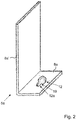
- Figure 2 shows part of a mounting device according to an embodiment of the present invention.
- the first fixing element 5a is now shown in detail in a perspective three-dimensional view.
- the longer leg is designated by reference number 8a 'and the shorter leg is referred to by reference number 8a.
- the length ratio in the cross section between the longer leg 8a 'and the shorter leg 8a is approximately between 1: 2 and 1: 3.
- connection 19 On the shorter leg 8a, two differently sized recesses 12, 12a are arranged, which are connected to one another via a connection 19.
- the two cutouts 12, 12a are partially and / or partially circular. Both centers of the cutouts 12, 12a lie on an axis which runs parallel to the longer side of the shorter leg 8a.
- the connection 19 also has a width that is smaller than the respective diameter of the cutouts 12, 12a. In other words, this represents a narrowing, constriction, a partial delimitation and / or a separation of the two cutouts from one another.
- the center point of the further cutout 12a is arranged in the middle of the shorter leg 8a.
- the larger recess 12 serves to insert part of the setting device 4, more precisely the control knob 11. This is first pressed or inserted into the recess 12 until the tapered area 11a of the control knob 11 is level with the further recess 12a and the connection 19 located. Then it is pressed laterally through the narrow point between the two recesses 12, 12a - connection 19 - into the smaller recess 12a.
- the tapered area 11a of the control knob 11, the width of the connection 19 and the smaller cutout 12a are designed such that the control knob 11 designed as a rotating body is essentially held captive in the smaller cutout 12a, i.e. a clamping device 10 by the elements 11 , 11a, 12, 12a, 19 is formed.
- the outer diameter of the tapered region 11a of the control knob 11 is chosen to be smaller than the inner diameter of the smaller recess 12a, but larger than the width of the connection 19.
- the inner diameter of the larger recess can be 7.2 mm
- control knob 11 can have an inner and / or outer entrainment profile on its underside, so that it can alternatively or additionally be actuated, for example, with a hexagon socket, a wrench or the like.
- steel in particular stainless steel
- the fixing elements 5a, 5b can serve as the material for the setting device 4 and the fixing elements 5a, 5b.
- the same also applies to the internal thread for the adjusting screw 9.
- the double-sided adhesive tape 7a, 7b, liquid adhesive, etc. can also be used.
- the assembly device, in particular the fixing elements 5a, 5b from plastic, for example as injection molded parts.
- Figure 3 shows part of a mounting device according to an embodiment of the present invention.
- FIG. 3 a further embodiment of the fixing element 5b, which cooperates with the receiving device 3 or can be connected, is shown, the viewing direction running along the installation direction 100 in the direction of the underside of the worktop 3.
- FIG. 3 Essentially, that shows Figure 3 a fixing element 5b according to Figure 1 .
- the fixing element 5b according to Figure 1 has the fixing element 5b according to Figure 3
- two drill holes 17 in which, for example, self-tapping screws can be used to connect the mounting device 1, more precisely the fixing element 5b, to the underside of the worktop 3.
- the fixing element 5b points in accordance with Figure 3 two spacers 18a, 18b, which are designed in particular for flat contact with the installation element 2.
- the two spacers 18a, 18b are separated here, but they can also extend in the form of a whole or only partially along the side of the fixing element 5b adjacent to the installation element 2.
- the spacers 18a, 18b can also be used for sufficiently flat contact Be L-shaped.
- the spacers 18a, 18b can be formed in one piece with the fixing element 5b or as separate parts. In the latter case, these can then be designed specifically for each installation element 2 and, for example, can be fixed on the fixing element 5b by means of a plug-in or clip connection, adhesive pads or surfaces or the like. This has the advantage that the fixing element 5b does not have to be completely adapted to the respective installation element 2, but only the corresponding spacers 18a, 18b.
- Figure 4 shows steps of a method according to an embodiment of the present invention.
- Figure 4 a method for installing an installation element in a receiving device along an installation direction by means of a mounting device according to one of claims 1-14.
- the process comprises the following steps:
- a first step S1 the installation element is inserted into the receiving device.
- step S2 the assembly device and the installation element are fixed to one another.
- step S3 the mounting device and the receiving device are fixed to one another.
- step S4 the relative position of the installation element and the receiving device is set such that a gap is formed in the direction of installation between the installation element and the receiving device in an overlap area that corresponds to the bearing surface of the installation element in the receiving device.
- a sealant in particular silicone, is introduced into the gap.
- step S6 the size of the gap is reduced by changing the relative position by means of the assembly device.
- Figure 5 shows a fixing element of a mounting device according to an embodiment of the present invention.
- Figure 5 essentially a fixing element 5a according to Figure 2 shown.
- the fixing element 5a is made in two parts with a first part 51 and a second part 52.
- Figure 5 shows in the upper part a plan view of the second part 52 parallel to the installation direction 100, in the lower part on the left a view of the fixing element 5a composed of the two parts 51, 52 perpendicular to the installation direction 100 with a plan view of the fixing surface 6a and in the lower part on the right a side view with a viewing direction perpendicular to the installation direction 100 and perpendicular to the fixing surface 6a.
- the first part 51 of the fixing element 5a is essentially plate-shaped and has two trapezoidal cutouts at its end facing the second part 52, which together with corresponding trapezoidal projections on the first part 51 have two dovetail connections 20a, 20b to provide a releasable form-fitting connection Allow 20 of the two parts 51, 52 to each other.
- the two parts 51, 52 can be made of sheet metal, for example.
- the fixing surface 6a of the fixing element 5a is provided here in particular exclusively by the first part 51.
- the second part 52 is L-shaped, the shorter end or the shorter leg of the L-shape comprising the trapezoidal projections for the dovetail connection 20.
- the shorter leg 8a of the fixing element 5a is thus formed exclusively by the second part 52, more precisely the longer leg of the L-shape of the second part 52.
- the longer leg 8a 'of the fixing element 5a is the shorter leg of the L-shape of the second Part 52 and formed by the first part 51.
- the thickness 152 of the second part 52 in particular in the region of the shorter leg of the L-shape of the second part 52, is smaller than the thickness 151 of the first part 51. This in particular prevents the two parts 51, 52 from tilting too much toward one another and thus a detachment of the two parts 51, 52 from each other.
- connection of the two parts 51, 52 can be secured or provided by a material and / or non-positive connection, for example an adhesive connection or the like.
- a material and / or non-positive connection for example an adhesive connection or the like.
- another form-fitting connection with a corresponding undercut can be used instead of or in combination with the dovetail connection 20.
- Figure 6 shows a mounting device according to an embodiment of the present invention schematically and in cross section.
- FIG 6 is essentially a mounting device 1 according to Figure 1 shown.
- a first fixing element 5a which is formed in two parts with a first substantially vertically oriented part 8a 'and a horizontally oriented part 8b.
- the first part 8a ' runs essentially vertically, a lower part 8a'-1 being connected to the installation element 2, and an upper part 8a'-2 being arranged at a distance from the installation element 2 by a horizontal offset 8c.
- the lower part 8a'-1 is as in Figure 1 described provided with a fixing surface 6a and fixed by means of a double-sided adhesive tape 7a to a partial area of the vertical edge 2a of the built-in element 2.
- the upper region 8a'-2 has two horizontal slots 8d-1, 8d-2 which are open from one side and into which the second part 8b engages as follows:
- the second part 8b has an essentially T-shaped profile.
- the head 8b ' is a square or rectangular plate - as in Figure 6 shown on the left - trained.
- the in Figure 6 horizontally extending leg of the T-shaped profile is designed to cooperate with the adjusting device 4.
- a section of the leg of the T-shaped profile is laterally inserted into one of the slots 8d-1, 8d-2 in accordance with the desired spacing or adjustment possibility of the adjusting device 4.
- the leg of the second part 8b forms in the horizontal plane - in Figure 6 left, plane perpendicular to the plane of the drawing parallel to the slots 8d-1, 8d-2 - also a surface, so that the leg 8b is secured against rotation about a horizontal axis.
- the horizontal offset 8c of the first part 8a 'and the horizontal thickness 153 of the head 8b' formed as a plate is dimensioned such that it is clamped between the installation element 2 and the upper part 8a'-2 and thus against tilting by one in Figure 6 horizontal axis on the right in the drawing plane is secured.
- the second fixing element 5b comprises, as in FIG Figure 1 an essentially horizontal area as a fixing surface 6b, on which a double-sided adhesive tape 7b is arranged, for fixing with the horizontally oriented area 3a of the underside of the worktop 3.
- the second fixing element 5b further has a set screw 9 "oriented in the vertical direction for vertical adjustment of the second fixing element 5b relative to the first fixing element 5a.
- the fixing surfaces 6a and 6b of the first fixing element 5a and the second fixing element 5b are rectangular here, in particular with an aspect ratio between 1: 1 and 1: 2, but other shapes are also, for example circular, trapezoidal, etc. The same applies accordingly to the aspect ratio or the edge lengths to one another.
- the second fixing element 5b together with the adjusting device 4 and the horizontal part 8b of the first fixing element 5a as a pre-assembled set and, on the other hand, to fix the vertical part 8a'-1 of the first fixing element 5a to the mounting element 2 already during production, for example. Since the thickness 153 is small, the distance between the worktop 3 and the built-in element 2 and thus the cutout in the worktop 3 for the built-in element 2 can also be kept as small as possible without the support surface 14 having a smaller size.
- At least one of the embodiments of the present invention enables an exact adjustable position of the built-in part and receiving device relative to one another. Another advantage is simple and inexpensive assembly and cost-effective production. Another advantage is the high flexibility with regard to possible areas of application.
Abstract
Die Erfindung betrifft eine Montagevorrichtung für ein Einbauelement, insbesondere ein Sanitäreinbauelement wie eine Spüle, ein Waschbecken oder dergleichen, zum Einsetzen in eine Aufnahmeeinrichtung entlang einer Einbaurichtung, wobei die Montagevorrichtung einerseits mit dem Einbauelement, andererseits mit der Aufnahmeeinrichtung derart zusammenwirkt, dass die relative Lage zumindest entlang der Einbaurichtung von Einbauelement und Aufnahmeeinrichtung zueinander mittels einer Einstelleinrichtung einstellbar ist und wobei die Einstelleinrichtung mit Festlegungsbereichen von Einbauelement und Aufnahmeeinrichtung zusammenwirkt, die unterschiedliche räumliche Orientierung haben, vorzugsweise wobei die Montagevorrichtung zwei Festlegungselemente umfasst, wobei eines mit dem Festlegungsbereich des Einbauelements, und eines mit dem Festlegungsbereich der Aufnahmevorrichtung verbindbar ist, insbesondere lösbar, vorzugsweise wobei zumindest eines der Festlegungselemente eine Festlegungsfläche aufweist, deren Flächennormale senkrecht zur Einbaurichtung orientiert ist.The invention relates to a mounting device for a built-in element, in particular a sanitary built-in element such as a sink, a sink or the like, for insertion into a receiving device along an installation direction, the mounting device interacting with the mounting element on the one hand and with the receiving device on the other hand such that the relative position at least along the installation direction of the installation element and the receiving device can be adjusted relative to one another by means of an adjustment device, and the adjustment device interacts with fixing areas of the installation element and the receiving device that have different spatial orientations, preferably wherein the mounting device comprises two fixing elements, one with the fixing area of the mounting element and one with the fixing area of the receiving device is connectable, in particular detachable, preferably with at least one of the fixing elements being a fixing element surface whose surface normal is oriented perpendicular to the direction of installation.
Description
Die Erfindung betrifft eine Montagevorrichtung für ein Einbauelement, insbesondere ein Sanitäreinbauelement wie eine Spüle, ein Waschbecken oder dergleichen, zum Einsetzen in eine Aufnahmeeinrichtung.The invention relates to a mounting device for a built-in element, in particular a sanitary built-in element such as a sink, a sink or the like, for insertion in a receiving device.
Die Erfindung betrifft weiter ein Verfahren zum Einbau eines Einbauelements in eine Aufnahmeeinrichtung mittels einer Montagevorrichtung.The invention further relates to a method for installing a built-in element in a receiving device by means of a mounting device.
Obwohl die vorliegende Erfindung allgemein auf beliebige Einbauelemente anwendbar ist, wird die vorliegende Erfindung in Bezug auf Einbauelemente in Form von Spülbecken beschrieben.Although the present invention is generally applicable to any built-in elements, the present invention will be described with respect to built-in elements in the form of sinks.
Obwohl die vorliegende Erfindung allgemein auf beliebige Aufnahmeeinrichtungen anwendbar ist, wird die vorliegende Erfindung in Bezug auf Aufnahmeeinrichtungen in Form von Küchenarbeitsplatten beschrieben.Although the present invention is generally applicable to any receptacle, the present invention will be described in relation to kitchen worktop receptacles.
Arbeitsplatten für Küchen dienen als Ablagefläche oder als Arbeitsfläche zur Zubereitung oder Vorbereitung von Speisen. Arbeitsplatten weisen üblicherweise Aussparungen auf, um beispielsweise ein Spülbecken oder dergleichen aufnehmen zu können. Hierbei sind verschiedene Anordnungen denkbar: der Rand der Spüle bzw. Spülbeckens kann über die Arbeitsplatte hinausragen, sodass die Arbeitsplatte die Spüle mittels eines umlaufenden Randes trägt. Dabei kann die Spüle über die Arbeitsplatte in vertikaler Richtung hinausragen bzw. vorstehen. Es ist ebenfalls denkbar, die Spüle so einzubauen, dass diese flächenbündig mit der Arbeitsplatte angeordnet ist, mit anderen Worten, dass eine gemeinsame Ebene von Oberkante der Arbeitsplatte und Oberkante der Spüle gebildet wird, sodass eine einfache Reinigung und eine hohe optische Anmutung erzielt wird. Um hierbei Wassereintritt in den Zwischenbereich zwischen Arbeitsplatte und Rand der Spüle zu vermeiden, wird üblicherweise Silikon in diesen Zwischenbereich eingebracht, welches sich nach einer gewissen Zeit verfestigt und den Wassereintritt verhindert. Dieser Zwischenbereich wird hierbei im Wesentlichen durch einen nicht von oben sichtbaren Bereich und einen von oben sichtbaren Bereich gebildet. Problematisch ist hierbei insbesondere beim flächenbündigen Einbau jedoch, dass die Spüle genau innerhalb der entsprechenden Öffnung der Arbeitsplatte ausgerichtet werden muss, und gleichzeitig eine wohldosierte Menge des Silikons in den Zwischenbereich eingebracht werden muss.Countertops for kitchens serve as storage space or as a work surface for preparing or preparing food. Worktops usually have cutouts to accommodate a sink or the like, for example. Various arrangements are conceivable here: the edge of the sink or sink can protrude beyond the worktop, so that the worktop supports the sink by means of a peripheral edge. The sink can protrude or protrude vertically from the worktop. It is also conceivable to install the sink in such a way that it is flush with the worktop, in other words that a common plane is formed between the top edge of the worktop and the top edge of the sink, so that easy cleaning and a high visual appearance are achieved. In order to prevent water from entering the intermediate area between the worktop and the edge of the sink, silicone is usually introduced into this intermediate area, which solidifies after a certain time and prevents water from entering. This intermediate area is essentially formed by an area not visible from above and an area visible from above. However, the problem with flush-mounted installation in particular is that the sink must be aligned exactly within the corresponding opening in the worktop, and at the same time a well-dosed amount of silicone must be introduced into the intermediate area.
Aus der
Aus der
Aus der
Nachteilig ist insgesamt, dass insbesondere beim flächenbündigen Einbau, das Silikon nur äußerst aufwendig in geeigneter Menge zwischen Spüle und Arbeitsplatte eingebracht werden kann. Ein weiterer Nachteil ist die mangelnde Flexibilität beim Positionieren von Spüle und Arbeitsplatte zueinander, was einen ungenauen und zeitintensiven Einbau zur Folge hat.Overall, it is disadvantageous that, particularly in the case of flush installation, the silicone can only be introduced in an appropriate amount between the sink and worktop in an extremely complex manner. Another disadvantage is the lack of flexibility when positioning the sink and worktop to each other, which results in inaccurate and time-consuming installation.
Eine Aufgabe der vorliegenden Erfindung ist es daher, eine Montagevorrichtung sowie ein Verfahren zum Einbau eines Einbauelements in eine Aufnahmeeinrichtung anzugeben, welche eine einfache, schnelle und genaue Montage des Einbauelements ermöglichen. Darüber hinaus soll die Montagevorrichtung flexibel für eine Vielzahl unterschiedlicher Einbauelemente einsetzbar sein. Eine weitere Aufgabe der vorliegenden Erfindung ist es, eine alternative Montagevorrichtung sowie ein alternatives Verfahren zum Einbau eines Einbauelements in eine Aufnahmeeinrichtung anzugeben.It is therefore an object of the present invention to provide a mounting device and a method for installing a built-in element in a receiving device, which enable simple, quick and accurate mounting of the built-in element. In addition, the assembly device should be able to be used flexibly for a large number of different installation elements. Another object of the present invention is to provide an alternative mounting device and an alternative method for installing a built-in element in a receiving device.
Die vorliegende Erfindung löst die vorstehend genannten Aufgaben mit einer Ausführungsform in Form einer Montagevorrichtung für ein Einbauelement, insbesondere ein Sanitäreinbauelement wie eine Spüle, ein Waschbecken oder dergleichen, zum Einsetzen in eine Aufnahmeeinrichtung entlang einer Einbaurichtung, dadurch, dass die Montagevorrichtung einerseits mit dem Einbauelement, andererseits mit der Aufnahmeeinrichtung derart zusammenwirkt, dass die relative Lage zumindest entlang der Einbaurichtung von Einbauelement und Aufnahmeeinrichtung zueinander mittels einer Einstelleinrichtung einstellbar ist und wobei die Einstelleinrichtung mit Festlegungsbereichen von Einbauelement und Aufnahmeeinrichtung zusammenwirkt, die unterschiedliche räumliche Orientierung aufweisen.The present invention achieves the above-mentioned objects with an embodiment in the form of a mounting device for a built-in element, in particular a sanitary built-in element such as a sink, a wash basin or the like, for insertion into a receiving device along an installation direction, in that the mounting device on the one hand with the built-in element, on the other hand cooperates with the receiving device in such a way that the relative position, at least along the installation direction of the installation element and the receiving device, can be adjusted with respect to one another by means of an adjusting device, and wherein the adjusting device interacts with fixing areas of the installation element and receiving device which have different spatial orientations.
Die vorliegende Erfindung löst die vorstehend genannten Aufgaben ebenfalls mit einer Ausführungsform in Form eines Verfahrens zum Einbau eines Einbauelements in eine Aufnahmeeinrichtung entlang einer Einbaurichtung mittels einer Montagevorrichtung gemäß einem der Ansprüche 1-14, umfassend die Schritte
- Einlegen des Einbauelements in die Aufnahmeeinrichtung,
- Festlegen von Montagevorrichtung und Einbauelement aneinander,
- Festlegen von Montagevorrichtung und Aufnahmeeinrichtung aneinander,
- Einstellen der relativen Lage von Einbauelement und Aufnahmeeinrichtung derart, dass in einem Überlappungsbereich, der zur Auflagefläche des Einbauelements in der Aufnahmeeinrichtung korrespondiert, zwischen Einbauelement und Aufnahmeeinrichtung in Einbaurichtung ein Spalt gebildet wird,
- Einbringen eines Dichtungsmittels, insbesondere von Silikon, in den Spalt, und
- Verringern der Größe des Spalts durch Ändern der relativen Lage mittels der Montagevorrichtung.
- Inserting the installation element into the receiving device,
- Fixing assembly device and installation element to each other,
- Fixing the mounting device and the receiving device to each other,
- Adjusting the relative position of the installation element and the receiving device such that a gap is formed in the direction of installation between the installation element and the receiving device in an overlap area that corresponds to the contact surface of the installation element in the receiving device.
- Introducing a sealant, in particular silicone, into the gap, and
- Reduce the size of the gap by changing the relative position using the mounting device.
Einer der damit erzielten Vorteile ist, dass damit eine exakte Positionierung von Einbauelement und Aufnahmeeinrichtung zueinander flexibel eingestellt werden kann, sodass beispielsweise Silikon in einen eingestellten Spalt einfach eingebracht werden kann und anschließend die Oberkanten von Einbauelement und Arbeitsplatte flächenbündig zueinander auf einfache und zuverlässige Weise eingestellt bzw. angeordnet werden können. Ein weiterer Vorteil ist, dass die Montagevorrichtung flexibel für eine Vielzahl unterschiedlicher Ausgestaltungen von Einbauelementen und Aufnahmeeinrichtungen verwendet werden kann, was die Herstellungskosten für die Montagevorrichtung verringert. Ein weiterer Vorteil ist die einfache Handhabbarkeit, da keinerlei aufwendige Einweisung in die Bedienung bzw. Handhabung der Montagevorrichtung erfolgen muss.One of the advantages achieved is that the exact positioning of the built-in element and receiving device can be flexibly adjusted relative to one another, so that, for example, silicone can be easily inserted into a set gap and then the upper edges of the built-in element and worktop can be set or flushed in a simple and reliable manner can be arranged. Another advantage is that the assembly device can be used flexibly for a large number of different configurations of installation elements and receiving devices, which reduces the manufacturing costs reduced for the mounting device. Another advantage is the ease of handling, since there is no need for extensive instruction in the operation or handling of the assembly device.
Weitere Merkmale, Vorteile und weitere Ausführungsformen der Erfindung sind im Folgenden beschrieben oder werden dadurch offenbar.Further features, advantages and further embodiments of the invention are described below or become apparent thereby.
Gemäß einer vorteilhaften Weiterbildung umfasst die Montagevorrichtung zwei Festlegungselemente, wobei eines mit dem Festlegungsbereich des Einbauelements, und eines mit dem Festlegungsbereich der Aufnahmeeinrichtung verbindbar ist, insbesondere lösbar. Einer der damit erzielten Vorteile ist, dass damit die Montagevorrichtung auf einfache Weise mit Einbauelement und Aufnahmeeinrichtung zur Einstellung der relativen Lage verbindbar ist. Ist die Montagevorrichtung lösbar mit Einbauelement bzw. Aufnahmeeinrichtung verbunden, kann diese nach Abschluss des Einbaus des Einbauelements wieder entfernt werden, sodass zum einen Kosten gespart werden, wenn die Einbauvorrichtung dann auch für andere Einbauelemente zu deren Einbau einsetzbar ist, zum anderen wird der durch die Montagevorrichtung benötigte Platz, beispielsweise unterhalb der Arbeitsplatte wieder erhöht.According to an advantageous development, the mounting device comprises two fixing elements, one being connectable, in particular detachable, to the fixing area of the mounting element and one to the fixing area of the receiving device. One of the advantages achieved in this way is that the mounting device can be connected in a simple manner to the installation element and receiving device for setting the relative position. If the mounting device is detachably connected to the installation element or receiving device, it can be removed again after the installation of the installation element has been completed, so that costs are saved on the one hand if the installation device can then also be used for other installation elements for its installation and Mounting device required space, for example, increased below the worktop again.
Gemäß einer weiteren vorteilhaften Weiterbildung weist zumindest eines der Festlegungselemente eine Festlegungsfläche auf, deren Flächennormale senkrecht zur Einbaurichtung orientiert ist. Damit kann die Montagevorrichtung auf flexible Weise auch bei beengten Platzverhältnissen an Einbauelement bzw. Aufnahmeeinrichtungen festgelegt werden.According to a further advantageous development, at least one of the fixing elements has a fixing surface, the surface normal of which is oriented perpendicular to the direction of installation. The mounting device can thus be fixed in a flexible manner even in the case of limited space on the installation element or receiving devices.
Gemäß einer weiteren vorteilhaften Weiterbildung weisen Festlegungsflächen der Festlegungselemente die gleiche geometrische Form auf, insbesondere sind diese rechteckig ausgebildet. Dies ermöglicht eine einfache und kostengünstige Herstellung der Montagevorrichtung.According to a further advantageous development, fixing surfaces of the fixing elements have the same geometric shape, in particular they are rectangular. This enables simple and inexpensive manufacture of the assembly device.
Gemäß einer weiteren vorteilhaften Weiterbildung weist zumindest eines der Festlegungselemente ein Klebeelement und/oder eine Unterdruckeinrichtung und/oder eine Schraubeinrichtung zum Festlegen des Festlegungselements an dem Einbauelement und/oder an der Aufnahmeeinrichtung auf. Vorteil hiervon ist, dass im Falle eines Klebeelements eine einfache und schnelle Festlegung der Montagevorrichtung an Einbauelement bzw. Aufnahmeeinrichtung möglich ist. Weist das Festlegungselement eine Unterdruckeinrichtung und/oder eine Schraubeinrichtung auf, ist eine besonders einfache Lösbarkeit von Montagevorrichtung und Einbauelement bzw. Aufnahmeeinrichtung nach erfolgter Montage des Einbauelements möglich. Die Schraubeinrichtung kann beispielsweise entsprechende Bohrlöcher für Schrauben umfassen, die in diese einsetzbar sind. Es ist ebenso denkbar, Schrauben unverlierbar in den Bohrlöchern anzuordnen, sodass diese nicht erst in diese eingeführt werden müssen. Darüber hinaus können entsprechend ausgebildete Festlegungsbereiche zum Zusammenwirken mit der Unterdruckeinrichtung am Einbauelement und/oder an der Aufnahmeeinrichtung bereits vorhanden sein oder während der Montage angeordnet werden.According to a further advantageous development, at least one of the fixing elements has an adhesive element and / or a vacuum device and / or a screwing device for fixing the fixing element to the mounting element and / or to the receiving device. The advantage of this is that in the case of an adhesive element, the mounting device can be fixed simply and quickly on the installation element or receiving device is possible. If the fixing element has a vacuum device and / or a screw device, it is particularly easy to detach the mounting device and the mounting element or mounting device after the mounting element has been installed. The screw device can, for example, include corresponding drill holes for screws that can be inserted into them. It is also conceivable to arrange screws captively in the drill holes so that they do not have to be inserted into them first. In addition, appropriately designed fixing areas for cooperation with the vacuum device can already be present on the installation element and / or on the receiving device or can be arranged during assembly.
Gemäß einer weiteren vorteilhaften Weiterbildung ist zumindest eines der Festlegungselemente L-förmig ausbildet, insbesondere wobei der kürzere Abschnitt des L-förmigen Festlegungselements im Wesentlichen senkrecht zur Einbaurichtung orientiert ist. Vorteil hiervon ist, dass damit ein einfaches und kostengünstiges Festlegungselement zur Verfügung gestellt werden kann, welches eine zuverlässige Einstellung der relativen Lage von Einbauelement und Aufnahmeeinrichtung ermöglicht.According to a further advantageous development, at least one of the fixing elements is L-shaped, in particular with the shorter section of the L-shaped fixing element being oriented essentially perpendicular to the direction of installation. The advantage of this is that it can be used to provide a simple and inexpensive fixing element which enables the relative position of the installation element and the receiving device to be set reliably.
Gemäß einer weiteren vorteilhaften Weiterbildung weist die Einstelleinrichtung ein Einstellelement auf, insbesondere umfassend eine Einstellschraube, welches mit einem der Festlegungselemente zur Einstellung der relativen Lage zusammenwirkt, insbesondere wobei das Festlegungselement ein zur Einstellungsschraube korrespondierendes Gewinde aufweist. Einer der damit erzielten Vorteile ist, dass eine einfache und gleichzeitig genaue Einstellung der relativen Lage von Einbauelement und Aufnahmeeinrichtung zueinander entlang der Einbaurichtung möglich ist.According to a further advantageous development, the adjusting device has an adjusting element, in particular comprising an adjusting screw, which interacts with one of the fixing elements for adjusting the relative position, in particular wherein the fixing element has a thread corresponding to the adjusting screw. One of the advantages achieved in this way is that a simple and at the same time precise adjustment of the relative position of the installation element and receiving device to one another is possible along the installation direction.
Gemäß einer weiteren vorteilhaften Weiterbildung wirkt die Einstelleinrichtung mit dem kürzeren Abschnitt des L-förmigen Festlegungselements zusammen. Damit wird der Bauraum senkrecht zur Einbaurichtung minimiert.According to a further advantageous development, the setting device interacts with the shorter section of the L-shaped fixing element. This minimizes the installation space perpendicular to the direction of installation.
Gemäß einer weiteren vorteilhaften Weiterbildung weist die Montagevorrichtung eine Klemmeinrichtung auf zur Bereitstellung einer Bedienposition für ein Einstellelement der Einstelleinrichtung. Auf diese Weise kann eine einfache Montage eines Einstellelements erfolgen, in dem dieses in einer Bedienposition verklemmt wird.According to a further advantageous development, the mounting device has a clamping device for providing an operating position for an adjusting element of the adjusting device. In this way, a simple assembly of a Adjustment element take place in that this is jammed in an operating position.
Gemäß einer weiteren vorteilhaften Weiterbildung ist das Einstellelement in eine erste Aussparung in einem der Festlegungselemente einführbar und über die erste Aussparung in eine zweite Aussparung zur Bereitstellung der Bedienposition in der zweiten Aussparung. Vorteil hiervon ist eine einfache Montage des Einstellelements für eine Betätigung der Einstelleinrichtung.According to a further advantageous development, the adjusting element can be inserted into a first recess in one of the fixing elements and, via the first recess, into a second recess to provide the operating position in the second recess. The advantage of this is a simple assembly of the adjusting element for actuating the adjusting device.
Gemäß einer weiteren vorteilhaften Weiterbildung umfasst das Einstellelement ein Betätigungselement in Form eines Drehknaufs und/oder ist mit einem Mitnahmeprofil ausgebildet, welches einen verjüngten Abschnitt, insbesondere in der Mitte seiner Erstreckung, aufweist. Auf diese Weise ist eine einfache Montage und Festlegung des Drehknaufs parallel zu seiner Erstreckungsrichtung durch den verjüngten Abschnitt möglich, ebenso wie eine einfache Bedienung des Betätigungselements zur Einstellung der relativen Lage zwischen Einbauelement und Aufnahmeeinrichtung.According to a further advantageous development, the setting element comprises an actuating element in the form of a rotary knob and / or is designed with a driving profile which has a tapered section, in particular in the middle of its extent. In this way, simple assembly and fixing of the rotary knob parallel to its direction of extension through the tapered section is possible, as is simple operation of the actuating element for setting the relative position between the installation element and the receiving device.
Gemäß einer weiteren vorteilhaften Weiterbildung ist der verjüngte Abschnitt des Betätigungselements einerseits zu der zweiten Aussparung, andererseits zu einer Verbindung zwischen erster und zweiter Aussparung zur Bereitstellung der Bedienposition korrespondierend ausgebildet. Damit kann auf einfache und zuverlässige Weise eine Bedienposition bzw. Unverlierbarkeit des Betätigungselements bereitgestellt werden.According to a further advantageous development, the tapered section of the actuating element is designed to correspond to the second recess on the one hand and to a connection between the first and second recess to provide the operating position on the other hand. An operating position or captivity of the actuating element can thus be provided in a simple and reliable manner.
Gemäß einer weiteren vorteilhaften Weiterbildung weist die Montagevorrichtung insbesondere zumindest eines der Festlegungselemente, zumindest ein Abstandselement auf zur Beabstandung der Montagevorrichtung von Einbauelement und/ oder Aufnahmeeinrichtung. Vorteil hiervon ist eine einfache und schnelle Montage der Montagevorrichtung mittels der Abstandshalter. Ein zeitintensives Ausrichten der Montagevorrichtung, insbesondere der Festlegungselemente entfällt damit.According to a further advantageous development, the mounting device has in particular at least one of the fixing elements, at least one spacer element for spacing the mounting device from the installation element and / or receiving device. The advantage of this is simple and quick assembly of the mounting device using the spacers. A time-consuming alignment of the mounting device, in particular the fixing elements, is therefore no longer necessary.
Gemäß einer weiteren vorteilhaften Weiterbildung ist zumindest eines der Festlegungselemente zumindest zweiteilig mit einem ersten Teil und einem zweiten Teil ausgebildet. Einer der damit erzielten Vorteile ist eine einfachere Montage und Demontage der Montagevorrichtung an Einbauelement und Aufnahmeeinrichtung.According to a further advantageous development, at least one of the fixing elements is formed at least in two parts with a first part and a second part. One of the advantages thus achieved is easier assembly and disassembly of the assembly device on the installation element and receiving device.
Gemäß einer weiteren vorteilhaften Weiterbildung sind der erste und zweite Teil mittels einer formschlüssigen Verbindung aneinander lösbar festlegbar. Vorteil ist eine einfache Festlegung der beiden Teile aneinander zur Bildung des Festlegungselements.According to a further advantageous development, the first and second parts can be releasably fixed to one another by means of a positive connection. The advantage is a simple fixing of the two parts to one another to form the fixing element.
Gemäß einer weiteren vorteilhaften Weiterbildung ist die Dicke der zumindest zwei Teile unterschiedlich. Damit kann auf einfache und kostengünstige Weise eine erhöhte Stabilität gegen Verkippen der beiden Teile gegeneinander bereitgestellt werden.According to a further advantageous development, the thickness of the at least two parts is different. In this way, increased stability against tilting of the two parts against each other can be provided in a simple and inexpensive manner.
Gemäß einer weiteren vorteilhaften Weiterbildung ist einer der beiden Teile des zumindest einen Festlegungselements L-förmig ausgebildet. Dadurch kann auf einfache Weise eine Orientierung des durch die beiden Teile gebildeten Festlegungselements in zwei unterschiedliche Richtungen ermöglicht werden.According to a further advantageous development, one of the two parts of the at least one fixing element is L-shaped. This allows the fixing element formed by the two parts to be oriented in two different directions in a simple manner.
Gemäß einer weiteren vorteilhaften Weiterbildung ist die formschlüssige Verbindung als zumindest eine Schwalbenschwanzverbindung ausgebildet. Diese ermöglicht eine stabile und gleichzeitig kostengünstige Bereitstellung einer Verbindung der beiden Teile.According to a further advantageous development, the positive connection is designed as at least one dovetail connection. This enables a stable and at the same time inexpensive provision of a connection between the two parts.
Gemäß einer weiteren vorteilhaften Weiterbildung sind der erste und zweite Teil senkrecht zur Einbaurichtung aneinander festlegbar. Damit ist eine besonders einfache Festlegung der beiden Teile aneinander möglich.According to a further advantageous development, the first and second parts can be fixed to one another perpendicular to the direction of installation. A particularly simple fixing of the two parts to one another is thus possible.
Gemäß einer weiteren vorteilhaften Weiterbildung beträgt das Verhältnis der Erstreckung von erstem und zweitem Teil parallel zur Einbaurichtung mindestens 1:3, insbesondere mindestens 1:5. Damit wird eine besonders zuverlässige Festlegung des Festlegungselements an dem entsprechenden Festlegungsbereich ermöglicht durch die Bereitstellung einer entsprechend großen zusammenhängenden Erstreckung eines Teils parallel zur Einbaurichtung und damit auch der Fläche des Teils, die mit dem entsprechenden Festlegungsbereich zusammenwirken kann.According to a further advantageous development, the ratio of the extent of the first and second part parallel to the direction of installation is at least 1: 3, in particular at least 1: 5. A particularly reliable fixing of the fixing element to the corresponding fixing area is thus made possible by the provision of a correspondingly large coherent extension of a part parallel to the installation direction and thus also the area of the part which can interact with the corresponding fixing area.
Gemäß einer weiteren vorteilhaften Weiterbildung ist eines der Festlegungselemente zumindest zweiteilig mit einem ersten Teil und einem zweiten Teil ausgebildet, die aneinander lösbar festlegbar sind. Einer der damit erzielten Vorteile ist, dass die Montage der Festlegungselemente bei beengten Platzverhältnissen an Einbauelement bzw. Aufnahmeeinrichtung vereinfacht wird.According to a further advantageous development, one of the fixing elements is formed at least in two parts with a first part and a second part, which can be detachably fixed to one another. One of the advantages achieved with this is that the mounting of the fixing elements in a confined space on the installation element or recording device is simplified.
Gemäß einer weiteren vorteilhaften Weiterbildung sind der erste Teil und der zweite Teil im Wesentlichen senkrecht zueinander anordenbar und wobei zumindest einer der Teile zumindest einen horizontalen Versatz und zumindest einen horizontalen Schlitz aufweist zum lösbaren Anordnen des zumindest einen anderen Teils. Damit können die beiden Teile auf besonders einfache Weise aneinander lösbar festgelegt werden.According to a further advantageous development, the first part and the second part can be arranged essentially perpendicular to one another and at least one of the parts has at least one horizontal offset and at least one horizontal slot for releasably arranging the at least one other part. The two parts can thus be fixed to one another in a particularly simple manner.
Gemäß einer weiteren vorteilhaften Weiterbildung weist der erste Teil mehrere horizontale Schlitze auf. Damit kann der zweite Teil beispielsweise bei senkrechter Orientierung des ersten Teils während des Einbaus auf verschiedenen Höhen angeordnet werden, sodass die Flexibilität beim Einbau erhöht wird.According to a further advantageous development, the first part has a plurality of horizontal slots. This means that the second part can be arranged at different heights, for example when the first part is oriented vertically, so that the flexibility during installation is increased.
Gemäß einer weiteren vorteilhaften Weiterbildung ist der zweite Teil im Querschnitt als T-förmiges Profil ausgebildet, insbesondere wobei der Kopf des T-förmigen Profils des zweiten Teils zwischen Einbauelement und erstem Teil anordenbar ist. Vorteil hiervon ist eine einfache und gleichzeitig zuverlässige Festlegung der beiden Teile aneinander.According to a further advantageous development, the second part is designed in cross section as a T-shaped profile, in particular wherein the head of the T-shaped profile of the second part can be arranged between the installation element and the first part. The advantage of this is a simple and at the same time reliable fixing of the two parts to one another.
Gemäß einer weiteren vorteilhaften Weiterbildung ist der horizontale Versatz so ausgebildet, dass dieser der horizontalen Dicke des Kopfs des T-förmigen Profils des zweiten Teils entspricht. Vorteil hiervon ist, dass der Kopf des T-förmigen Profils des zweiten Teils zwischen Einbauelement und erstem Teil lösbar und auf besonders einfache Weise durch Verklemmen festgelegt wird. Aufwendige anderen Festlegungen wie Verschrauben oder Verkleben können damit entfallen.According to a further advantageous development, the horizontal offset is designed such that it corresponds to the horizontal thickness of the head of the T-shaped profile of the second part. The advantage of this is that the head of the T-shaped profile of the second part between the installation element and the first part is detachable and fixed in a particularly simple manner by jamming. Elaborate other specifications such as screwing or gluing can be omitted.
Gemäß einer weiteren vorteilhaften Weiterbildung des Verfahrens wird die Montagevorrichtung nach erfolgter Montage von Einbauelement und Aufnahmeeinrichtung entfernt. Damit wird einerseits eine besonders kostengünstige Herstellung der Montagevorrichtung ermöglicht, gleichzeitig wird die Flexibilität erhöht, da die Montagevorrichtung dann für weitere Einbauelemente verwendet werden kann. Ebenso wird der Bauraum optimiert, da die Montagevorrichtung nur während der Montage, nicht jedoch ständig an Einbauelement bzw. Aufnahmeeinrichtung verbleiben muss.According to a further advantageous development of the method, the mounting device is removed after the mounting element and receiving device have been installed. On the one hand, this enables a particularly cost-effective production of the assembly device, at the same time increasing the flexibility, since the assembly device can then be used for further installation elements. The installation space is also optimized, since the assembly device only has to remain on the installation element or receiving device during assembly, but not constantly.
Gemäß einer weiteren vorteilhaften Weiterbildung des Verfahrens wird die Montagevorrichtung an dem Einbauelement und/oder an der Aufnahmeeinrichtung mittels eines doppelseitigen Klebebandes und/oder mittels einer Schraubverbindung festgelegt. Dies ermöglicht eine einfache, zuverlässige und gleichzeitig kostengünstige Festlegung der Montagevorrichtung an Einbauelement und/oder an der Aufnahmeeinrichtung.According to a further advantageous development of the method, the assembly device fixed on the installation element and / or on the receiving device by means of a double-sided adhesive tape and / or by means of a screw connection. This enables a simple, reliable and, at the same time, inexpensive fixing of the mounting device on the installation element and / or on the receiving device.
Weitere wichtige Merkmale und Vorteile der Erfindung ergeben sich aus den Unteransprüchen, aus den Zeichnungen, und aus dazugehöriger Figurenbeschreibung anhand der Zeichnungen.Further important features and advantages of the invention emerge from the subclaims, from the drawings and from the associated description of the figures on the basis of the drawings.
Es versteht sich, dass die vorstehend genannten und die nachstehend noch zu erläuternden Merkmale nicht nur in der jeweils angegebenen Kombination, sondern auch in anderen Kombinationen oder in Alleinstellung verwendbar sind, ohne den Rahmen der vorliegenden Erfindung zu verlassen.It goes without saying that the features mentioned above and those yet to be explained below can be used not only in the combination indicated in each case, but also in other combinations or on their own without departing from the scope of the present invention.
Bevorzugte Ausführungen und Ausführungsformen der Erfindung sind in den Zeichnungen dargestellt und werden in der nachfolgenden Beschreibung näher erläutert, wobei sich gleiche Bezugszeichen auf gleiche oder ähnliche oder funktional gleiche Bauteile oder Elemente beziehen.Preferred embodiments and embodiments of the invention are shown in the drawings and are explained in more detail in the following description, the same reference numerals referring to the same or similar or functionally identical components or elements.
- Figur 1Figure 1
- eine Montagevorrichtung gemäß einer Ausführungsform der vorliegenden Erfindung;a mounting device according to an embodiment of the present invention;
- Figur 2Figure 2
- einen Teil einer Montagevorrichtung gemäß einer Ausführungsform der vorliegenden Erfindung;a part of a mounting device according to an embodiment of the present invention;
- Figur 3Figure 3
- einen Teil einer Montagevorrichtung gemäß einer Ausführungsform der vorliegenden Erfindung;a part of a mounting device according to an embodiment of the present invention;
- Figur 4Figure 4
- Schritte eines Verfahrens gemäß einer Ausführungsform der vorliegenden Erfindung;Steps of a method according to an embodiment of the present invention;
- Figur 5Figure 5
- ein Festlegungselement einer Montagevorrichtung gemäß einer Ausführungsform der vorliegenden Erfindung; unda fixing element of a mounting device according to an embodiment of the present invention; and
- Figur 6Figure 6
- eine Montagevorrichtung gemäß einer Ausführungsform der vorliegenden Erfindunga mounting device according to an embodiment of the present invention
Im Detail ist in
Das zweite Festlegungselement 5b umfasst einen im Wesentlichen horizontalen Bereich als Festlegungsfläche 6b, auf der ein doppelseitiges Klebeband 7b angeordnet ist, zur Festlegung mit einem horizontal orientierten Bereich 3a einer Unterseite einer Arbeitsplatte 3. Das zweite Festlegungselement 5b weist weiter ein in senkrechter Richtung orientiertes Innengewinde 9' auf, in das eine Schraube 9 eingreift. Das Innengewinde 9' sowie die zugehörige Einstellschraube 9 und einen mit der Einstellschraube 9 zusammenwirkenden Bedienknauf 11, der wiederrum einen verjüngten Abschnitt 11a aufweist, bildet eine Einstelleinrichtung 4. Die Einstelleinrichtung 4 wirkt mit dem horizontal verlaufenden Abschnitt 8a des ersten L-förmigen Festlegungselements 5a derart zusammen, dass der Bedienknauf 11 sich an dem ersten Festlegungselement 5a abstützt und gleichzeitig die Schraube 9 betätigt werden kann. Sind nun also beide Festlegungselemente 5a, 5b an Einbauelement 2 und Unterseite der Arbeitsplatte 3 festgelegt, kann mittels der Einstelleinrichtung 4 der vertikale Abstand zwischen Einbauelement 2 und Arbeitsplatte 3 entlang der Einbaurichtung 100 eingestellt werden, sodass in einem Überlappungsbereich 13 der zur Auflagefläche 14 in der Arbeitsplatte 3 für das Einbauelement 2 ein korrespondierender Spalt 15 gebildet werden kann. Mittels der Einstelleinrichtung 4 wird dieser dann so eingestellt, dass ein Dichtmittel, insbesondere Silikon 16, in diesen gespritzt werden kann. Anschließend wird über die Einstelleinrichtung 4 der vertikale Abstand, sprich die Breite des Spalts 15, wieder vermindert und so eingestellt, dass diese ein gewünschtes Niveau von Arbeitsplatte 3 und Oberkante des Einbauelements 2 zueinander erreicht, insbesondere Einbauelement 2 und Arbeitsplatte 3 flächenbündig zueinander angeordnet werden. Durch die Verringerung des Spalts 15 wird Silikon 16 aus dem Spalt 15 herausgedrückt. Dieses wird anschließend entfernt.The
Die Festlegungsflächen 6a bzw. 6b von erstem Festlegungselement 5a bzw. zweitem Festlegungselement 5b sind hier rechteckförmig ausgebildet, insbesondere mit einem Seitenverhältnis zwischen 1:1 und 1:2, jedoch sind auch andere Formen, beispielsweise kreisförmig, trapezförmig oder dergleichen denkbar. Gleiches gilt entsprechend für das Seitenverhältnis bzw. die Kantenlängen zueinander.The fixing surfaces 6a and 6b of the
Mit anderen Worten umfasst die Montagevorrichtung 1 somit eine Gewindeplatte 5b, eine Einstellschraube 9, einen Verbindungswinkel 5a und zwei doppelseitige Klebebänder 7a, 7b. Zur flächenbündigen Montage wird das Einbauelement 2, beispielsweise ein Spülbecken oder dergleichen, in einen entsprechenden Ausschnitt der Arbeitsplatte 3 eingelegt und ausgerichtet. Vorgesehene Festlegungsbereiche 2a, 3a werden gereinigt, gegebenenfalls Schutzfolien von doppelseitigem Klebeband auf den Festlegungsbereichen 6a, 6b der Montagevorrichtung 1 abgezogen und die Montagevorrichtung 1 entsprechend an Einbauelement 2 und Unterseite der Arbeitsplatte 3 geklebt. Nach Festlegung der Montagevorrichtung 1 wird über die Einstelleinrichtung 4 das Einbauelement 2 so weit nach oben geschraubt, bis ein ausreichend großer Spalt 15 zwischen Arbeitsplattenoberseite, bzw. Auflagefläche 14 und Unterseite des Randes des Einbauelements 2 entsteht. In diesen Spalt 15 wird dann Silikon 16 eingebracht. Nach dem Einbringen des Silikons 16 wird das Einbauelement 2 mittels der Einstellschraube 9 in die gewünschte Einbauposition nach unten geschraubt und nach Erreichen der gewünschten Einbauposition für das Einbauelement 2 in Bezug auf die Arbeitsplatte 3 das Silikon 16 abgezogen.In other words, the
Im Detail ist nun in perspektivischer dreidimensionaler Ansicht das erste Festlegungselement 5a gezeigt. Hierbei ist der längere Schenkel mit Bezugszeichen 8a' bezeichnet und der kürzere Schenkel mit Bezugszeichen 8a. Das Längenverhältnis im Querschnitt zwischen längerem Schenkel 8a' und kürzerem Schenkel 8a beträgt hierbei ca. zwischen 1:2 und 1:3.The
Am kürzeren Schenkel 8a sind zwei unterschiedlich große Aussparungen 12, 12a angeordnet, welche miteinander über eine Verbindung 19 verbunden sind. Die beiden Aussparungen 12, 12a sind teilweise und/oder abschnittsweise kreisförmig ausgebildet. Beide Mittelpunkte der Aussparungen 12, 12a liegen dabei auf einer Achse, welche parallel zur längeren Seite des kürzeren Schenkels 8a verläuft. Die Verbindung 19 weist weiter eine Breite auf, die kleiner ist als der jeweilige Durchmesser der Aussparungen 12, 12a. Mit anderen Worten stellt diese eine Verengung, Einschnürung, eine teilweise Abgrenzung und/oder eine Trennung der beiden Aussparungen voneinander dar. Der Mittelpunkt der weiteren Aussparung 12a ist dabei in der Mitte des kürzeren Schenkels 8a angeordnet.On the
Die größere Aussparung 12 dient hierbei zum Einführen eines Teils der Einstelleinrichtung 4, genauer des Bedienknaufs 11. Dieser wird zunächst in die Aussparung 12 gedrückt bzw. eingeführt, bis sich der verjüngte Bereich 11a des Bedienknaufs 11 auf Höhe der weiteren Aussparung 12a und der Verbindung 19 befindet. Anschließend wird dieser seitlich durch die Engstelle zwischen den beiden Aussparungen 12, 12a - Verbindung 19 - in die kleinere Aussparung 12a gedrückt. Der verjüngte Bereich 11a des Bedienknaufs 11, die Breite der Verbindung 19 und die kleinere Aussparung 12a sind dabei so zueinander ausgebildet, dass der als Rotationskörper ausgebildete Bedienknauf 11 im Wesentlichen in der kleineren Aussparung 12a unverlierbar gehalten wird, also eine Klemmeinrichtung 10 durch die Elemente 11, 11a, 12, 12a, 19 gebildet wird. Eine Rotationsbewegung des Bedienknaufs 11 ist jedoch möglich, da der Außendurchmesser des verjüngten Bereichs 11a des Bedienknaufs 11 kleiner gewählt wird als der Innendurchmesser der kleineren Aussparung 12a, jedoch größer als die Breite der Verbindung 19. Beispielsweise kann der Innendurchmesser der größeren Aussparung 7,2 mm, der Innendurchmesser der kleineren Aussparung 3,3 mm, die Breite der Verbindung 19 3,1 mm und der Außendurchmesser des verjüngten Bereichs 11a des Bedienknaufs 11 3,2 mm betragen, um die beschriebene Montage, Bedienung und Unverlierbarkeit bereitzustellen.The
Weiterhin kann der Bedienknauf 11 ein inneres und/oder äußeres Mitnahmeprofil auf seiner Unterseite aufweisen, sodass dieser alternativ oder zusätzlich beispielsweise auch mit einem Innensechskant, einem Schraubenschlüssel oder ähnlichem betätigt werden kann.Furthermore, the
Als Material für die Einstelleinrichtung 4 und die Festlegungselemente 5a, 5b kann beispielsweise Stahl, insbesondere Edelstahl, dienen. Gleiches gilt auch für das Innengewinde für die Einstellschraube 9. Anstelle des doppelseitigen Klebebandes 7a, 7b können auch Flüssigkleber, etc. verwendet werden. Weiterhin ist denkbar, die Montagevorrichtung, insbesondere die Festlegungselemente 5a, 5b, aus Kunststoff, beispielsweise als Spritzgussteile, zu fertigen.For example, steel, in particular stainless steel, can serve as the material for the
Im Detail ist in
Im Wesentlichen zeigt die
Unabhängig hiervon weist das Festlegungselement 5b gemäß
Im Detail ist in
Dabei erfolgt in einem ersten Schritt S1 ein Einlegen des Einbauelements in die Aufnahmeeinrichtung.In a first step S1, the installation element is inserted into the receiving device.
Dabei erfolgt in einem weiteren Schritt S2 ein Festlegen von Montagevorrichtung und Einbauelement aneinander.In a further step S2, the assembly device and the installation element are fixed to one another.
Dabei erfolgt in einem weiteren Schritt S3 ein Festlegen von Montagevorrichtung und Aufnahmeeinrichtung aneinander.In a further step S3, the mounting device and the receiving device are fixed to one another.
Dabei erfolgt in einem weiteren Schritt S4 ein Einstellen der relativen Lage von Einbauelement und Aufnahmeeinrichtung derart, dass in einem Überlappungsbereich, der zur Auflagefläche des Einbauelements in der Aufnahmeeinrichtung korrespondiert, zwischen Einbauelement und Aufnahmeeinrichtung in Einbaurichtung ein Spalt gebildet wird.In a further step S4, the relative position of the installation element and the receiving device is set such that a gap is formed in the direction of installation between the installation element and the receiving device in an overlap area that corresponds to the bearing surface of the installation element in the receiving device.
Dabei erfolgt in einem weiteren Schritt S5 ein Einbringen eines Dichtungsmittels, insbesondere von Silikon, in den Spalt.In a further step S5, a sealant, in particular silicone, is introduced into the gap.
Dabei erfolgt in einem weiteren Schritt S6 ein Verringern der Größe des Spalts durch Ändern der relativen Lage mittels der Montagevorrichtung.In a further step S6, the size of the gap is reduced by changing the relative position by means of the assembly device.
Im Detail ist in
Der erste Teil 51 des Festlegungselements 5a ist im Wesentlichen plattenförmig ausgebildet und weist an seinem, dem zweiten Teil 52 zugewandten Ende zwei trapezförmige Aussparungen auf, die zusammen mit entsprechenden trapezförmigen Vorsprüngen an dem ersten Teil 51 zwei Schwalbenschwanzverbindungen 20a, 20b zur Bereitstellung einer lösbaren formschlüssigen Verbindung 20 der beiden Teile 51, 52 aneinander ermöglichen. Hierbei können die beiden Teile 51, 52 beispielsweise aus Blech hergestellt sein.The
Zwar ist das Festlegungselement 5a zweiteilig ausgelegt, die Festlegungsfläche 6a des Festlegungselements 5a wird hier insbesondere ausschließlich durch den ersten Teil 51 bereitgestellt.Although the fixing
Der zweite Teil 52 ist L-förmig ausgeführt, wobei das kürzere Ende bzw. der kürzere Schenkel der L-Form die trapezförmigen Vorsprünge für die Schwalbenschwanzverbindung 20 umfasst. Mit anderen Worten und mit Bezug auf das Festlegungselement 5a gemäß
Zusätzlich kann auch eine oder mehrere Sicherungen gegen ein Lösen angeordnet werden und/oder zusätzlich oder alternativ die Verbindung der beiden Teile 51, 52 durch eine stoffschlüssige und/oder kraftschlüssige Verbindung, beispielsweise eine Klebeverbindung oder dergleichen gesichert bzw. bereitgestellt werden. Weiterhin kann alternativ anstelle der Schwalbenschanzverbindung 20 oder in Kombination mit dieser auch eine andere formschlüssige Verbindung mit entsprechender Hinterschneidung verwendet werden.In addition, one or more safeguards against loosening can also be arranged and / or additionally or alternatively, the connection of the two
In
Weiterhin weist der obere Bereich 8a'-2 zwei horizontale von einer Seite offene Schlitze 8d-1, 8d-2 auf, in die der zweite Teil 8b folgendermaßen eingreift: Der zweite Teil 8b weist ein im Wesentlichen T-förmiges Profil auf. Der Kopf 8b' ist dabei als quadratische oder rechteckförmige Platte - wie in
Das zweite Festlegungselement 5b umfasst wie in
Mittels der Ausführungsform der
In einer weiteren hier nicht gezeigten Ausführungsform ist es möglich, auf eine Festlegung der Festlegungsfläche 6b an der Arbeitsplatte zu verzichten, sodass mittels der Einstelleinrichtung 4 und über die am Einbauelement 2 festgelegte Festlegungsfläche 6a mittels der Montagevorrichtung ein Verklemmen von Einbauelement 2 und Arbeitsplatte 3 ermöglicht wird. Dadurch kann die Montage insgesamt weiter vereinfacht werden.In a further embodiment, not shown here, it is possible to make a determination the fixing
Zusammenfassend ermöglicht zumindest eine der Ausführungsformen der vorliegenden Erfindung eine exakte einstellbare Position von Einbauteil und Aufnahmeeinrichtung zueinander. Ein weiterer Vorteil ist eine einfache und kostengünstige Montage sowie eine kostengünstige Herstellung. Ein weiterer Vorteil ist die hohe Flexibilität in Bezug auf mögliche Einsatzbereiche.In summary, at least one of the embodiments of the present invention enables an exact adjustable position of the built-in part and receiving device relative to one another. Another advantage is simple and inexpensive assembly and cost-effective production. Another advantage is the high flexibility with regard to possible areas of application.
Obwohl die vorliegende Erfindung anhand bevorzugter Ausführungsbeispiele beschrieben wurde, ist sie nicht darauf beschränkt, sondern auf vielfältige Weise modifizierbar.Although the present invention has been described on the basis of preferred exemplary embodiments, it is not restricted to these but can be modified in a variety of ways.
- 11
- MontagevorrichtungMounting device
- 22nd
- EinbauelementBuilt-in element
- 2a2a
- Festlegungsbereich EinbauelementDetermination area built-in element
- 33rd
- AufnahmeeinrichtungReception facility
- 3a3a
- Festlegungsbereich AufnahmeeinrichtungDetermination area reception facility
- 44th
- EinstelleinrichtungAdjustment device
- 5a, 5b5a, 5b
- FestlegungselementFixing element
- 6a, 6b6a, 6b
- FestlegungsflächeFixing area
- 6a-516a-51
- Teilfestlegungsfläche erster Teil FestlegungselementPartial fixing area first part fixing element
- 6a-526a-52
- Teilfestlegungsfläche zweiter Teil FestlegungselementPartial setting area, second part of the setting element
- 7a, 7b7a, 7b
- Doppelseitiges KlebebandDouble sided tape
- 8a, 8b8a, 8b
- Kürzerer SchenkelShorter thigh
- 8a'8a '
- Längerer SchenkelLonger leg
- 8a'-1, 8a'-28a'-1, 8a'-2
- Teilpart
- 8b'8b '
- Kopfhead
- 8c8c
- VersatzOffset
- 8d-1, 8d-28d-1, 8d-2
- Schlitzslot
- 99
- EinstellschraubeAdjusting screw
- 9'9 '
- Innengewindeinner thread
- 9"9 "
- GewindestiftGrub screw
- 1010th
- KlemmeinrichtungClamping device
- 1111
- BedienknaufControl knob
- 11a11a
- Verjüngter Bereich BedienknaufTapered area of the control knob
- 12, 12a12, 12a
- AussparungRecess
- 12a12a
- Verjüngter Bereich AussparungTapered recess area
- 1313
- ÜberlappungsbereichOverlap area
- 1414
- AuflageflächeContact surface
- 1515
- Spaltgap
- 1616
- DichtungsmittelSealant
- 1717th
- BohrlöcherBoreholes
- 18a, 18b18a, 18b
- AbstandshalterSpacers
- 1919th
- Verbindung AussparungenConnection cutouts
- 2020th
- Verbindung Teile FestlegungselementConnection parts fixing element
- 20a, 20b20a, 20b
- SchwalbenschwanzverbindungDovetail joint
- 5151
- erster Teil Festlegungselementfirst part fixing element
- 5252
- Zweiter Teil FestlegungselementSecond part of the fixing element
- 100100
- EinbaurichtungInstallation direction
- 151151
- Dicke erster Teil FestlegungselementThick first part fixing element
- 152152
- Dicke zweiter Teil FestlegungselementThick second part fixing element
- 153153
- Dickethickness
Claims (15)
dadurch gekennzeichnet, dass
die Montagevorrichtung (1) einerseits mit dem Einbauelement (2), andererseits mit der Aufnahmeeinrichtung (3) derart zusammenwirkt, dass die relative Lage zumindest entlang der Einbaurichtung (100) von Einbauelement (2) und Aufnahmeeinrichtung (3) zueinander mittels einer Einstelleinrichtung (4) einstellbar ist und wobei die Einstelleinrichtung (4) mit Festlegungsbereichen (2a, 3a) von Einbauelement (2) und Aufnahmeeinrichtung (3) zusammenwirkt, die unterschiedliche räumliche Orientierung haben, vorzugsweise wobei
die Montagevorrichtung (1) zwei Festlegungselemente (5a, 5b) umfasst, wobei eines (5a) mit dem Festlegungsbereich (2a) des Einbauelements (2), und eines (5b) mit dem Festlegungsbereich (3a) der Aufnahmevorrichtung verbindbar ist, insbesondere lösbar, vorzugsweise wobei
zumindest eines (5a) der Festlegungselemente (5a, 5b) eine Festlegungsfläche (6a) aufweist, deren Flächennormale senkrecht zur Einbaurichtung (100) orientiert ist.Mounting device (1) for a built-in element (2), in particular a sanitary built-in element such as a sink, a wash basin or the like, for insertion into a receiving device (3) along an installation direction (100),
characterized in that
the assembly device (1) interacts on the one hand with the installation element (2) and on the other hand with the receiving device (3) in such a way that the relative position at least along the installation direction (100) of the installation element (2) and receiving device (3) to one another by means of an adjusting device (4 ) is adjustable and wherein the setting device (4) interacts with fixing areas (2a, 3a) of the installation element (2) and the receiving device (3), which have different spatial orientations, preferably wherein
the mounting device (1) comprises two fixing elements (5a, 5b), one (5a) being connectable, in particular detachable, to the fixing area (2a) of the mounting element (2) and one (5b) being connected to the fixing area (3a) of the receiving device, preferably where
at least one (5a) of the fixing elements (5a, 5b) has a fixing surface (6a), the surface normal of which is oriented perpendicular to the direction of installation (100).
die Einstelleinrichtung (4) mit dem kürzeren Abschnitt (8a) des L-förmigen Festlegungselements (5a) zusammenwirkt.Mounting device according to one of claims 1-4, characterized in that the adjusting device (4) has an adjusting element (9, 11), in particular comprising an adjusting screw, which interacts with one of the fixing elements (5b) for adjusting the relative position, in particular wherein that Fixing element (5b) has a thread (9 ') corresponding to the adjusting screw, preferably wherein
the adjusting device (4) interacts with the shorter section (8a) of the L-shaped fixing element (5a).
das Einstellelement (9, 11) in eine erste Aussparung (12) in einem der Festlegungselemente (5a) einführbar ist und über die erste Aussparung (12) in eine zweite Aussparung (12a) zur Bereitstellung der Bedienposition in der zweiten Aussparung (12a).Mounting device according to one of claims 1-5, characterized in that the mounting device (1) has a clamping device (10, 19) for providing an operating position for an adjusting element (9, 11) of the adjusting device (4), preferably wherein
the adjusting element (9, 11) can be inserted into a first recess (12) in one of the fixing elements (5a) and via the first recess (12) into a second recess (12a) to provide the operating position in the second recess (12a).
der verjüngte Abschnitt (11a) des Betätigungselements (11) einerseits zu der zweiten Aussparung (12a), andererseits zu einer Verbindung (19) zwischen erster und zweiter Aussparung (12, 12a) zur Bereitstellung der Bedienposition korrespondierend ausgebildet ist.Mounting device according to claim 5 or 6, characterized in that the adjusting element (9, 11) comprises an actuating element (11) and this is designed in the form of a rotary knob and / or with a driving profile which has a tapered section (11a), in particular in the Middle of its extent, preferably, wherein
the tapered section (11a) of the actuating element (11) is designed on the one hand to correspond to the second recess (12a) and on the other hand to form a connection (19) between the first and second recesses (12, 12a) to provide the operating position.
der erste und zweite Teil mittels einer formschlüssigen Verbindung aneinander lösbar festlegbar sind, vorzugsweise wobei
die Dicke der zumindest zwei Teile unterschiedlich ist.Mounting device according to claim 1, characterized in that at least one of the fixing elements (5a, 5b) is formed at least in two parts with a first part and a second part, preferably wherein
the first and second parts can be releasably fixed to one another by means of a positive connection, preferably wherein
the thickness of the at least two parts is different.
der erste Teil (8a', 8a", 8c) und der zweite Teil (8b, 8b') im Wesentlichen senkrecht zueinander anordenbar sind und wobei zumindest einer der Teile (8a', 8a", 8c) zumindest einen horizontalen Versatz (8c) und zumindest einen horizontalen Schlitz (8d, 8d-1) aufweist zum lösbaren Anordnen des zumindest einen anderen Teils (8b, 8b'), vorzugsweise wobei
der erste Teil (8a', 8a", 8c) mehrere horizontale Schlitze (8d, 8d-1) aufweist.Mounting device according to claim 1, characterized in that one of the fixing elements (5a) is formed at least in two parts with a first part (8a ', 8a ", 8c) and a second part (8b, 8b'), which can be releasably fixed to one another, preferably wherein
the first part (8a ', 8a ", 8c) and the second part (8b, 8b') can be arranged essentially perpendicular to one another and at least one of the parts (8a ', 8a", 8c) has at least one horizontal offset (8c) and has at least one horizontal slot (8d, 8d-1) for releasably arranging the at least one other part (8b, 8b '), preferably wherein
the first part (8a ', 8a ", 8c) has a plurality of horizontal slots (8d, 8d-1).
die Montagevorrichtung (1) nach erfolgter Montage von Einbauelement (2) und Aufnahmeeinrichtung (3) entfernt wird, vorzugsweise wobei
die Montagevorrichtung (1) an dem Einbauelement (2) und/oder an der Aufnahmeeinrichtung (3) mittels jeweils eines doppelseitigen Klebebandes (7a, 7b) und/oder mittels einer Schraubverbindung (17) festgelegt wird.A method for installing an installation element (2) in a receiving device (3) along an installation direction (100) by means of a mounting device (1) according to one of claims 1-14, comprising the steps
the mounting device (1) is removed after the installation of the installation element (2) and the receiving device (3), preferably wherein
the mounting device (1) is fixed on the installation element (2) and / or on the receiving device (3) by means of a double-sided adhesive tape (7a, 7b) and / or by means of a screw connection (17).
Applications Claiming Priority (2)
| Application Number | Priority Date | Filing Date | Title |
|---|---|---|---|
| DE102018217527 | 2018-10-12 | ||
| DE102019201198.5A DE102019201198A1 (en) | 2018-10-12 | 2019-01-30 | Mounting system for a built-in element |
Publications (1)
| Publication Number | Publication Date |
|---|---|
| EP3636841A1 true EP3636841A1 (en) | 2020-04-15 |
Family
ID=67551103
Family Applications (1)
| Application Number | Title | Priority Date | Filing Date |
|---|---|---|---|
| EP19190133.9A Pending EP3636841A1 (en) | 2018-10-12 | 2019-08-05 | Mounting device for an installation element |
Country Status (2)
| Country | Link |
|---|---|
| EP (1) | EP3636841A1 (en) |
| DE (1) | DE102019201198A1 (en) |
Citations (7)
| Publication number | Priority date | Publication date | Assignee | Title |
|---|---|---|---|---|
| US2495853A (en) * | 1946-02-27 | 1950-01-31 | Lindgren Hugo | Sink and drainboard structure |
| US2646575A (en) * | 1949-03-18 | 1953-07-28 | Luxene Inc | Sink and drainboard assembly |
| US2864099A (en) * | 1955-10-12 | 1958-12-16 | Church Of Religious Science | Sink mounting |
| US4432106A (en) * | 1982-06-23 | 1984-02-21 | Arro-Mac Manufacturing Inc. | Clamp assembly for self-rimming sinks or basins |
| WO2000052270A2 (en) | 1999-03-04 | 2000-09-08 | Elkay Manufacturing Company | Mounting device for securing a sink to a countertop and method of using same |
| EP1772566A2 (en) | 2005-10-05 | 2007-04-11 | Niro-Plan Ag | Element to be built-in in a kitchen |
| JP2016195664A (en) | 2015-04-03 | 2016-11-24 | パナソニックIpマネジメント株式会社 | Mounting method and mounting structure of sink |
-
2019
- 2019-01-30 DE DE102019201198.5A patent/DE102019201198A1/en active Pending
- 2019-08-05 EP EP19190133.9A patent/EP3636841A1/en active Pending
Patent Citations (7)
| Publication number | Priority date | Publication date | Assignee | Title |
|---|---|---|---|---|
| US2495853A (en) * | 1946-02-27 | 1950-01-31 | Lindgren Hugo | Sink and drainboard structure |
| US2646575A (en) * | 1949-03-18 | 1953-07-28 | Luxene Inc | Sink and drainboard assembly |
| US2864099A (en) * | 1955-10-12 | 1958-12-16 | Church Of Religious Science | Sink mounting |
| US4432106A (en) * | 1982-06-23 | 1984-02-21 | Arro-Mac Manufacturing Inc. | Clamp assembly for self-rimming sinks or basins |
| WO2000052270A2 (en) | 1999-03-04 | 2000-09-08 | Elkay Manufacturing Company | Mounting device for securing a sink to a countertop and method of using same |
| EP1772566A2 (en) | 2005-10-05 | 2007-04-11 | Niro-Plan Ag | Element to be built-in in a kitchen |
| JP2016195664A (en) | 2015-04-03 | 2016-11-24 | パナソニックIpマネジメント株式会社 | Mounting method and mounting structure of sink |
Also Published As
| Publication number | Publication date |
|---|---|
| DE102019201198A1 (en) | 2020-04-16 |
Similar Documents
| Publication | Publication Date | Title |
|---|---|---|
| EP1902814B1 (en) | Construction kit comprising at least one panel | |
| DE2514357C3 (en) | Fitting for the pivotable connection of a furniture panel with a fixed furniture part | |
| DE202013101469U1 (en) | Shower door assembly | |
| EP2808457A2 (en) | Water draining device for a sanitary installation, such as a shower basin that is level with the floor | |
| EP0168672B1 (en) | Door of built-in kitchen appliance with door panel | |
| EP0645957B1 (en) | Cabinet frame | |
| EP0237768B1 (en) | Device for spatially connecting components | |
| EP3009692A1 (en) | Connecting device | |
| EP2138069B1 (en) | Component for manufacturing a multi-function writing or work desk | |
| EP3636841A1 (en) | Mounting device for an installation element | |
| EP1645756B1 (en) | Attaching and connecting element for a system for the setting up of devices to clamp workpieces | |
| EP3549486B1 (en) | Work table for a laboratory automation system and laboratory automation system including said work table | |
| EP1582802B1 (en) | Stand with fixture for a flat screen | |
| DE19906571C2 (en) | Mounting plate for functional elements | |
| DE69813106T2 (en) | Device for the mutual connection of flat elements, in particular for the assembly of pieces of furniture | |
| DE102011000196B4 (en) | fastening device | |
| DE102017008020B4 (en) | modular wall | |
| DE8011513U1 (en) | SANITARY OBJECT WITH HIDDEN WALL FASTENING, E.g. SOAP DISH, GLASS HOLDER, TOWEL HOLDER, TOWEL RING, SHELF AND THE LIKE | |
| EP1637749B1 (en) | Fastening device with a screw | |
| DE102005013086B4 (en) | System consisting of a plinth panel and a cover | |
| EP3888497A1 (en) | Device for fixing a piece of furniture to a base and method for fixing a furniture body to a base | |
| AT391353B (en) | Connector for connecting two components | |
| DE19527855C1 (en) | Fastener for rectangular sink placed on base | |
| AT501632B1 (en) | DEVICE FOR FIXING A WINDOW FRAME | |
| DE1908035C3 (en) | Device for hanging a pipe or the like |
Legal Events
| Date | Code | Title | Description |
|---|---|---|---|
| PUAI | Public reference made under article 153(3) epc to a published international application that has entered the european phase |
Free format text: ORIGINAL CODE: 0009012 |
|
| STAA | Information on the status of an ep patent application or granted ep patent |
Free format text: STATUS: THE APPLICATION HAS BEEN PUBLISHED |
|
| AK | Designated contracting states |
Kind code of ref document: A1 Designated state(s): AL AT BE BG CH CY CZ DE DK EE ES FI FR GB GR HR HU IE IS IT LI LT LU LV MC MK MT NL NO PL PT RO RS SE SI SK SM TR |
|
| AX | Request for extension of the european patent |
Extension state: BA ME |
|
| STAA | Information on the status of an ep patent application or granted ep patent |
Free format text: STATUS: REQUEST FOR EXAMINATION WAS MADE |
|
| 17P | Request for examination filed |
Effective date: 20200929 |
|
| RBV | Designated contracting states (corrected) |
Designated state(s): AL AT BE BG CH CY CZ DE DK EE ES FI FR GB GR HR HU IE IS IT LI LT LU LV MC MK MT NL NO PL PT RO RS SE SI SK SM TR |
|
| STAA | Information on the status of an ep patent application or granted ep patent |
Free format text: STATUS: EXAMINATION IS IN PROGRESS |
|
| 17Q | First examination report despatched |
Effective date: 20210809 |