EP3636576A1 - Elevator guide rail support assemblies - Google Patents
Elevator guide rail support assemblies Download PDFInfo
- Publication number
- EP3636576A1 EP3636576A1 EP18306340.3A EP18306340A EP3636576A1 EP 3636576 A1 EP3636576 A1 EP 3636576A1 EP 18306340 A EP18306340 A EP 18306340A EP 3636576 A1 EP3636576 A1 EP 3636576A1
- Authority
- EP
- European Patent Office
- Prior art keywords
- guide rail
- rail
- support assembly
- rail support
- backing plate
- Prior art date
- Legal status (The legal status is an assumption and is not a legal conclusion. Google has not performed a legal analysis and makes no representation as to the accuracy of the status listed.)
- Pending
Links
Images






Classifications
-
- B—PERFORMING OPERATIONS; TRANSPORTING
- B66—HOISTING; LIFTING; HAULING
- B66B—ELEVATORS; ESCALATORS OR MOVING WALKWAYS
- B66B7/00—Other common features of elevators
- B66B7/02—Guideways; Guides
- B66B7/023—Mounting means therefor
- B66B7/026—Interconnections
-
- B—PERFORMING OPERATIONS; TRANSPORTING
- B66—HOISTING; LIFTING; HAULING
- B66B—ELEVATORS; ESCALATORS OR MOVING WALKWAYS
- B66B7/00—Other common features of elevators
- B66B7/02—Guideways; Guides
-
- B—PERFORMING OPERATIONS; TRANSPORTING
- B66—HOISTING; LIFTING; HAULING
- B66B—ELEVATORS; ESCALATORS OR MOVING WALKWAYS
- B66B7/00—Other common features of elevators
- B66B7/02—Guideways; Guides
- B66B7/023—Mounting means therefor
- B66B7/024—Lateral supports
Definitions
- the subject matter disclosed herein generally relates to elevator systems and, more particularly, to guide rail section support assemblies and wall mounting of such guide rail sections.
- the guide rail is typically formed of different rail sections that are joined together.
- the rail sections may also be affixed to a wall of an elevator shaft.
- current systems use a junction fishplate to join and connect two adjacent rail sections.
- a wall mounting bracket is connected to the rail sections.
- further embodiments may include a connector connecting the junction element to the mounting element.
- further embodiments may include that the connector is adjustable to adjust a separation distance between the junction element and the mounting element.
- further embodiments may include a stop, the stop positioned within the junction element and dividing the rail cavity into a first rail cavity and a second rail cavity, wherein the stop, the first extension, the second extension, and the backing plate define the respective first rail cavity and the second rail cavity.
- further embodiments may include that the stop has a profile in a shape of a cross-section of a rail section.
- further embodiments may include that the stop is part of the mounting element.
- further embodiments may include that the backing plate of the junction element is formed from a first backing plate and a second backing plate, wherein each of the first backing plate and the second backing plate are attached to the mounting element.
- further embodiments may include that the first extension is connected to the first backing plate and the second extension is connected to the second backing plate.
- further embodiments may include that each of the first and second backing plates are connected to the mounting element.
- further embodiments may include that the mounting element is connectable to a wall of an elevator shaft by at least one fastener.
- elevator systems having a guide rail support assembly including one or more of the features described above are provided.
- further embodiments may include a first rail section installed into the rail cavity and a second rail section installed into the rail cavity to form a portion of a guide rail.
- further embodiments may include that a stop is positioned between the first rail section and the second rail section within the guide rail support assembly
- further embodiments may include that the guide rail is one of a guide rail for an elevator car and a guide rail for a counterweight.
- further embodiments may include that the mounting element is fixedly attached to a wall of an elevator shaft.
- FIG. 1A is a perspective view of an elevator system 101 including an elevator car 103, a counterweight 105, a roping 107, a guide rail 109, a machine 111, a position encoder 113, and a controller 115.
- the elevator car 103 and counterweight 105 are connected to each other by the roping 107.
- the roping 107 may include or be configured as, for example, ropes, steel cables, and/or coated-steel belts.
- the counterweight 105 is configured to balance a load of the elevator car 103 and is configured to facilitate movement of the elevator car 103 concurrently and in an opposite direction with respect to the counterweight 105 within an elevator shaft 117 and along the guide rail 109.
- the roping 107 engages the machine 111, which is part of an overhead structure of the elevator system 101.
- the machine 111 is configured to control movement between the elevator car 103 and the counterweight 105.
- the position encoder 113 may be mounted on an upper sheave of a speed-governor system 119 and may be configured to provide position signals related to a position of the elevator car 103 within the elevator shaft 117. In other embodiments, the position encoder 113 may be directly mounted to a moving component of the machine 111, or may be located in other positions and/or configurations as known in the art.
- the controller 115 is located, as shown, in a controller room 121 of the elevator shaft 117 and is configured to control the operation of the elevator system 101, and particularly the elevator car 103.
- the controller 115 may provide drive signals to the machine 111 to control the acceleration, deceleration, leveling, stopping, etc. of the elevator car 103.
- the controller 115 may also be configured to receive position signals from the position encoder 113.
- the elevator car 103 may stop at one or more landings 125 as controlled by the controller 115.
- the controller 115 can be locatcd and/or configured in other locations or positions within the elevator system 101.
- the machine 111 may include a motor or similar driving mechanism.
- the machine 111 is configured to include an electrically driven motor.
- the power supply for the motor may be any power source, including a power grid, which, in combination with other components, is supplied to the motor.
- FIG. 1A is merely a non-limiting example presented for illustrative and explanatory purposes.
- FIG. 1B is a side view schematic illustration of the elevator car 103 as operably connected to the guide rail 109.
- the elevator car 103 connects to the guide rail 109 by one or more guiding devices 127.
- the guiding devices 127 may be a guide shoe, a roller, etc.
- the guide rail 109 defines a guide rail track that has a base 129 and a blade 131 extending therefrom.
- the guiding devices 127 are configured to run along and/or engage with the blade 131.
- the guide rail 109 mounts to a wall 133 of the elevator shaft 117 by one or more brackets 135.
- the brackets 135 are configured to fixedly mount to the wall 133 and the base 129 of the guide rail 109 fixedly attaches to the brackets 135.
- a guide rail of a counterweight of an elevator system may be similarly configured.
- the guide rail comprises a plurality of sections that are joined together to form the guide rail along which an elevator car may travel.
- a junction fishplate is fixed by steel nuts and screws to the two adjacent and connected rails, as will be appreciated by those of skill in the art.
- the individual sections of the assembled guide rail may be affixed to a wall of the elevator shaft using brackets (e.g., brackets 135 shown in FIG. 1B ).
- brackets e.g., brackets 135 shown in FIG. 1B .
- FIG. 2A is a front elevation view of the guide rail 209
- FIG. 2B is a top-down illustration of the guide rail 209 viewed along the line B-B shown in FIG. 2A
- the guide rail 209 is supported by and mounted to an elevator shaft wall 233 by one or more brackets 235.
- the brackets 235 may wrap partially around a base 229 of the guide rail 209, with a blade 231 extending from the base 229.
- the guide rail 209 is formed from multiple rail sections 237a, 237b.
- the rail sections 237a, 237b are fixedly connected to each other with a junction fishplate 239.
- the junction fishplate 239 provides a support and connection between the rail sections 237a, 237b.
- the rail sections 237a, 237b are connected to the junction fishplate 239 by respective fasteners 241a, 241b.
- the fasteners 241a, 241b may be bolts or other similar elements, and as such occupy some amount of space (e.g., as shown in FIG. 2B ). Because of this, the bracket 235 cannot be connected to the guide rail 209 at the same location as the junction fishplate 239.
- FIG. 2B illustrates the guide rail 209 as viewed along the line B-B shown in FIG. 2A .
- the fasteners 241a (and the fasteners 241b) extend away from the wall 233, thus occupying additional volume within an elevator shaft. That is, the fasteners 241a, 241b extend into the elevator shaft in order to secure the rail sections 237a, 237b together to form the guide rail 209.
- guide rail support assemblies are provided that incorporate both the function of a junction fishplate and a wall mount.
- the guide rail support assemblies of the present disclosure are composed of two parts.
- a first part is a rail engagement portion (e.g., a clamp) which has the form (cross-sectional shape) of the rail sections to receive rail sections.
- the ends of rail sections may slide into the rail engagement portion and be secured therein without the use of screws or other securing mechanisms.
- a horizontal stop e.g., small plate
- the stop may have a similar shape or geometry as a cross-section of a rail section.
- a wall mount is attached to and configured to support the rail engagement portion.
- the wall mount can be varied in position or even extension into an elevator shaft (i.e., distance extending from wall) by a sliding system to adjust the gap with the wall.
- the wall mount can be fixed by screws, dowels, or other similar fasteners (e.g., same fixation as current guide rail brackets).
- the guide rail support assemblies can be mounted above each lower rail section to make the junction between adjacent rail sections and can be directly fixed to the elevator shaft wall.
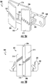
- FIGS. 3A-3B schematic illustrations of a guide rail support assembly 300 in accordance with an embodiment of the present disclosure are shown.
- the guide rail support assembly 300 is configured to attach to a wall of an elevator shaft and receive sections of the guide rail to enable connection thereof to form a guide rail. That is, the guide rail support assembly 300 provides both junction fishplate functionality and wall bracket functionality, in a single, unitary structure or component.
- FIG. 3A is an isometric illustration of the guide rail support assembly 300 and FIG. 3B is a front elevation illustration of the guide rail support assembly 300.
- the guide rail support assembly 300 includes a junction element 302 and a mounting element 304.
- the junction element 302 in this embodiment, is affixed to or connected to the mounting element 304 by a connector 306.
- the connector 306 may be a fixed element (e.g., rigid metal) or may be an adjustable element, such that a separation distance between the junction element 302 and the mounting element 304 may be changed or adjusted. Accordingly, in some embodiments, the specific relative position of the junction element 302 may be set relative to the mounting element 304 after installation into an elevator shaft.
- the junction element 302 is configured to receive two separate rail sections, to allow connection of a first rail section and a second rail section, similar to prior junction fishplates. However, in some embodiments, fasteners may not be required. As shown, the junction element 302 has a backing plate 308, a first extension 310, a second extension 312, and a stop 314. The junction element 302 defines, in this embodiment, two rail cavities: a first rail cavity 316 and a second rail cavity 318 between the backing plate 308, the first extension 310, the second extension 312, and the stop 314. The rail cavities 316, 318 are shaped to receive a base of a rail section of a guide rail. The stop 314 is arranged to limit the extent to which a given rail section can fit into the junction element 302. In some embodiments, the rail cavities 316, 318 are sized to enable a press-fit or interference fit between the features of the junction element 302 and a rail section inserted into the rail cavities 316, 318.
- the mounting element 304 of the guide rail support assembly 300 is configured to enable mounting and connection to a wall of an elevator shaft.
- the mounting element 304 may be a plate 320 having one or more apertures for affixing the mounting element 304 to the wall.
- the junction element 302, the mounting element 304, and the connector 306 may be integrally formed or cast, or two of the elements may be formed as a single, cast element, with the third being attached or affixed, and in some embodiments, moveable or adjustable engagement may be provided.
- the guide rail support assembly 300 is a single, unitary structure. That is, the junction element 302 and the mounting element 304 are a unitary body, and may be formed or cast from a single material.
- one or more aspects of the guide rail support assemblies of the present disclosure may be formed from multiple separate parts that are joined or attached to make up the guide rail support assembly. For example, in one non-limiting example of a multi-part guide rail support assembly, five separate pieces may be assembled together. In one such example, a first part may be mounted to an elevator shaft wall, with this part also forming a stop. Two separate backing plates, which may be "L" shaped can then attach to the mount/stop part.
- two separate extension elements that define one or more rail cavities, as described above, may be affixed to the backing plates. This is merely for descriptive purposes, and one or more of the above described separate elements may be joined to form a unitary part (e.g., the extensions and backing plates may be unitary parts that are affixed to the mount/stop).
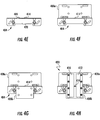
- FIGS. 4A-4H schematic illustrations of an assembly process of a guide rail support assembly 400 in accordance with an embodiment of the present disclosure is shown.
- FIGS. 4A-4D are side view illustrations of the assembly process and FIGS. 4E-4H are respective front elevation views of the assembly.
- FIG. 4A is a side elevation view of a first aspect of an assembly process
- FIG. 4E is a front elevation view of the same first aspect of the assembly process.
- FIGS. 4B and 4F , FIGS. 4C and 4G , and FIGS. 4D and 4H are similarly combinations of views of the assembly process illustrating side and front elevation views.
- FIGS. 4D and 4H illustrate the guide rail support assembly 400 as fully assembled.
- FIGS. 4A and 4E illustrate a mounting element 404 as affixed to a wall 433 of an elevator shaft.
- the mounting element 404 is affixed to the wall 433 by a fastener.
- the mounting element 404 includes a plate 420, a connector 406, and a stop 414. That is, in this embodiment, the mounting element 404 is arranged to provide three separate functions (i.e., mounting, placement of a junction element relative to the wall 433, and provide a stop between rail sections installed into the guide rail support assembly 400).
- FIGS. 4B and 4F a part of a junction element of the guide rail support assembly 400 is assembled to the mounting element 404. As shown, a first backing plate 408a is positioned relative to the mounting element 404, and, specifically, relative to the stop 414 and the connector 406.
- a second backing plate 408b is arranged opposite the first backing plate 408a relative to the mounting element 404.
- the first backing plate 408a and the second backing plate 408b may be fixedly attached to each other and to the mounting element 404 by one or more fasteners, as illustratively shown in FIG. 4D .
- a first extension 410 and a second extension 412 may be affixed to the first backing plate 408a and the second backing plate 408b by one or more fasteners.
- the guide rail support assembly 400 is assembled and able to receive and support one or more rail sections, similar to the guide rail support assembly described with respect to FIGS. 3A-3B .
- FIGS. 5A-5B schematic illustrations of a guide rail support assembly 500 in accordance with an embodiment of the present disclosure are shown.
- FIG. 5A is a front elevation illustration of the guide rail support assembly 500, which may have a construction substantially similar to that shown and described with respect to FIGS. 4A-4H .
- FIG. 5B is a side elevation illustration of the guide rail support assembly 500 as installed to a wall 533 of an elevator shaft and joining a first rail section 537a and a second rail section 537b.
- the guide rail support assembly 500 is similar to the guide rail support assembly 400 shown and described in FIGS. 4A-4H , above, and thus some features may not be described in detail again.
- the guide rail support assembly 500 includes a junction element 502 and a mounting element 504.
- the junction element 502 in this embodiment, is formed, in part, by a first backing plate 508a and a second backing plate 508b that are joined together by first fasteners 522, with a first extension 510 and a second extension 512 affixed thereto, to define one or more rail cavities, as described herein.
- a connector 506 Positioned between the first backing plate 508a and the second backing plate 508b is a connector 506 that is part of the mounting element 504, and an optional stop 514 extending from the connector 506.
- the stop 514 may separate the junction element 502 into two separate rail cavities, as described below. In embodiments without the stop 514, a single rail cavity is defined within the junction element 502 (e.g., as shown and described in FIG. 7 ).
- the stop 514 and the connector 506 extend from a plate 520 of the mounting element 504, as shown in FIG. 5B (and as shown in FIGS. 4A-4H ).
- the mounting element 504 includes the plate 520, the connector 506, and the stop 514 as a unitary structure. It will be appreciated that, in this embodiment, the stop 514 is a part of both the junction element 502 (defining the separate rail cavities) and the mounting element 504 (being physically part thereof).
- the junction element 502 defines a first rail cavity 516 and a second rail cavity 518 as described above, and shown in FIG. 5A .
- the first rail cavity 516 is defined between the first backing plate 508a, parts of the first and second extensions 510, 512, and the stop 514.
- the second rail cavity 518 is defined between the second backing plate 508b, parts of the first and second extensions 510, 512, and the stop 514 (an opposite side of the stop 514 from the first rail cavity 516).
- the first backing plate 508a, the second backing plate 508b, and the stop 514 of the mounting element 504 may be connected by one or more second fasteners 524 through the connector 506 and/or the stop 514.
- one or more third fasteners 526 are provided to fixedly connect the plate 520 of the mounting element 504 to the wall 533, as shown in FIG. 5B .
- a rail base 529a of the first rail section 537a is inserted into the first rail cavity 516 (shown in FIG. 5A ) and contacts the stop 514.
- a rail base 529b of the second rail section 537b is inserted into the second rail cavity 518 (shown in FIG. 5A ) and contacts the stop 514.
- the stop 514 may have the same shape, size, and dimensions as the first and second rail sections 537a, 537b such that the stop 514 forms a continuous guide rail when the first and second rail sections 537a, 537b are installed into or joined together by the guide rail support assembly 500.
- first fasteners 522 fixedly connect the first and second extensions 510, 512 to the first and second backing plates 508a, 508b. Further, the first fasteners 522 can enable a clamping force to be applied to the first and second extensions 510, 512 to provide secured and forced contact and support for the rail sections 537a, 537b.
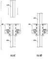
- FIGS. 6A-6D a series of schematic illustrations of a process for guide rail construction or installation in accordance with an embodiment of the present disclosure is shown.
- a guide rail support assembly 600 is provided for joining, connecting, and installing a first rail section 637a to a second rail section 637b.
- the guide rail support assembly 600 may be substantially similar in configuration as that shown and described with respect to FIGS. 4A-4H and FIGS. 5A-B .
- the first rail section 637a is installed within an elevator shaft.
- the first rail section 637a may be a portion of a guide rail for an elevator car, counterweight, or other traveling component of an elevator system.
- the guide rail support assembly 600 may be affixed to an end of the first rail section 637a.
- an end of the first rail section 637a may be fit within a first rail cavity of the guide rail support assembly 600.
- One or more fasteners may be used to securely attach the guide rail support assembly 600 to the end of the first rail section 637a.
- the end of the first rail section 637a may contact and stop within the guide rail support assembly 600 by a stop of the guide rail support assembly 600, as described above.
- the guide rail support assembly 600 may be fixedly connected or attached to a wall of an elevator shaft, thus fixing the first rail section 637a in position.
- the second rail section 637b may be installed into a second rail cavity of the guide rail support assembly 600.
- Respective fasteners may be tightened to secure the second rail section 637b within the guide rail support assembly 600.
- the functionality of a junction fishplate and a wall bracket may be provided in a single component (e.g., guide rail support assembly 600), thus increasing installation efficiency and reducing the volume which such components occupy.
- the fasteners that are used to secure the rail sections within the rail cavities may be omitted.
- a press-fit or interference fit may be employed.
- such pressed engagement may be completely omitted, wherein the ends of the rail sections slide into the rail cavities, but no additional clamping or other engagement is necessary to securely support and hold the respective rail sections.
- FIG. 7 is a side elevation illustration of the guide rail support assembly 700 as installed to a wall 733 of an elevator shaft and joining a first rail section 737a and a second rail section 737b.
- the guide rail support assembly 700 has a construction substantially similar to that shown and described with respect to FIGS. 5A-5B , and as illustratively shown in FIG. 5B .
- the primary difference between the guide rail support assembly 500 and the guide rail support assembly 700 of FIG. 7 is that the guide rail support assembly 700 does not include a stop. That is, the stop, described above, is an optional feature of the guide rail support assemblies of the present disclosure. Accordingly, a junction element of the guide rail support assembly 700 defines a single rail cavity that can receive ends of two different rail sections.
- first rail section 737a and the second rail section 737b may abut or contact each other within the rail cavity of the guide rail support assembly 700.
- first rail section 737a and the second rail section 737b may have a mortise and tenon joint configuration.
- keyway or slot configurations may be implemented. That is, various alternative mechanisms for aligning and joining the rail sections within a guide rail support assembly of the present disclosure may be implemented without departing from the scope of the present disclosure.
- the backing plates each have different shapes and sizes.
- the specific shape and sizes of the backing plates may be selected for a particular project or installation, and thus the illustrative shapes and sizes are merely for example only.
- the shape and size of the backing plates may be substantially similar or the same, such that they may be interchangeable.
- embodiments provided herein enable dual functionality within a single structure. That is, guide rail support assemblies of the present disclosure provide both wall-attachment (mounting bracket) and rail section joining (junction fishplate) within a single component. As such, efficiencies in installation of guide rails may be achieved. Further, such systems can eliminate fasteners associated with a junction fishplate, thus reducing the volume occupied by such features.
Landscapes
- Lift-Guide Devices, And Elevator Ropes And Cables (AREA)
Abstract
Guide rail support assemblies for elevator systems are provided. The guide rail support assemblies include a junction element comprising a backing plate, a first extension, and a second extension, the junction element defining a rail cavity, wherein the rail cavity is configured to receive two rail sections, wherein the junction element is configured to join a first rail section to a second rail section and a mounting element configured to attach to a wall of an elevator shaft, wherein the mounting element is connected to the junction element.
Description
- The subject matter disclosed herein generally relates to elevator systems and, more particularly, to guide rail section support assemblies and wall mounting of such guide rail sections.
- Current elevator systems use one type of guide rail to form a guide rail upon which an elevator car and/or counterweight may travel. The guide rail is typically formed of different rail sections that are joined together. The rail sections may also be affixed to a wall of an elevator shaft. To achieve such joining and mounting, current systems use a junction fishplate to join and connect two adjacent rail sections. Further, at different locations, in order to reduce profiles and number of components, a wall mounting bracket is connected to the rail sections.
- According to some embodiments, guide rail support assemblies for elevator systems are provided. The guide rail support assemblies include a junction element comprising a backing plate, a first extension, and a second extension, the junction element defining a rail cavity, wherein the rail cavity is configured to receive two rail sections, wherein the junction element is configured to join a first rail section to a second rail section and a mounting element configured to attach to a wall of an elevator shaft, wherein the mounting element is connected to the junction element.
- In addition to one or more of the features described above, or as an alternative, further embodiments may include a connector connecting the junction element to the mounting element.
- In addition to one or more of the features described above, or as an alternative, further embodiments may include that the connector is adjustable to adjust a separation distance between the junction element and the mounting element.
- In addition to one or more of the features described above, or as an alternative, further embodiments may include a stop, the stop positioned within the junction element and dividing the rail cavity into a first rail cavity and a second rail cavity, wherein the stop, the first extension, the second extension, and the backing plate define the respective first rail cavity and the second rail cavity.
- In addition to one or more of the features described above, or as an alternative, further embodiments may include that the stop has a profile in a shape of a cross-section of a rail section.
- In addition to one or more of the features described above, or as an alternative, further embodiments may include that the stop is part of the mounting element.
- In addition to one or more of the features described above, or as an alternative, further embodiments may include that the backing plate of the junction element is formed from a first backing plate and a second backing plate, wherein each of the first backing plate and the second backing plate are attached to the mounting element.
- In addition to one or more of the features described above, or as an alternative, further embodiments may include that the first extension is connected to the first backing plate and the second extension is connected to the second backing plate.
- In addition to one or more of the features described above, or as an alternative, further embodiments may include that each of the first and second backing plates are connected to the mounting element.
- In addition to one or more of the features described above, or as an alternative, further embodiments may include that the mounting element is connectable to a wall of an elevator shaft by at least one fastener.
- According to some embodiments, elevator systems having a guide rail support assembly including one or more of the features described above are provided.
- In addition to one or more of the features described above, or as an alternative, further embodiments may include a first rail section installed into the rail cavity and a second rail section installed into the rail cavity to form a portion of a guide rail.
- In addition to one or more of the features described above, or as an alternative, further embodiments may include that a stop is positioned between the first rail section and the second rail section within the guide rail support assembly
- In addition to one or more of the features described above, or as an alternative, further embodiments may include that the guide rail is one of a guide rail for an elevator car and a guide rail for a counterweight.
- In addition to one or more of the features described above, or as an alternative, further embodiments may include that the mounting element is fixedly attached to a wall of an elevator shaft.
- The foregoing features and elements may be combined in various combinations without exclusivity, unless expressly indicated otherwise. These features and elements as well as the operation thereof will become more apparent in light of the following description and the accompanying drawings. It should be understood, however, that the following description and drawings are intended to be illustrative and explanatory in nature and non-limiting.
- The subject matter is particularly pointed out and distinctly claimed at the conclusion of the specification. The foregoing and other features, and advantages of the present disclosure are apparent from the following detailed description taken in conjunction with the accompanying drawings in which:
-
FIG. 1A is a schematic illustration of an elevator system that may employ various embodiments of the disclosure; -
FIG. 1B is a side view schematic illustration of an elevator car ofFIG. 1A attached to a guide rail track; -
FIG. 2A is a schematic illustration of a guide rail fixed to a wall by a bracket and multiple rail sections joined by a junction fishplate, in accordance with a typical arrangement; -
FIG. 2B is a view of the guide rail ofFIG. 2A as viewed along the line B-B ofFIG. 2A ; -
FIG. 3A is an isometric schematic illustration of a guide rail support assembly in accordance with an embodiment of the present disclosure; -
FIG. 3B is a front elevation illustration of the guide rail support assembly ofFIG. 3A ; -
FIGS. 4A-4H are illustrative schematic views of assembly of a guide rail support assembly in accordance with an embodiment of the present disclosure; -
FIG. 5A is a front elevation illustration of a guide rail support assembly in accordance with an embodiment of the present disclosure; -
FIG. 5B is a side view illustration of the guide rail support assembly ofFIG. 5A as attached to a wall and connecting rail sections of a guide rail; -
FIGS. 6A-6D are a series of schematic illustrations of an installation process of a guide rail employing a guide rail support assembly in accordance with an embodiment of the present disclosure; and -
FIG. 7 is a side view illustration of a guide rail support assembly in accordance with an embodiment of the present disclosure as attached to a wall and connecting rail sections of a guide rail. -
FIG. 1A is a perspective view of anelevator system 101 including anelevator car 103, acounterweight 105, aroping 107, aguide rail 109, amachine 111, aposition encoder 113, and acontroller 115. Theelevator car 103 andcounterweight 105 are connected to each other by theroping 107. Theroping 107 may include or be configured as, for example, ropes, steel cables, and/or coated-steel belts. Thecounterweight 105 is configured to balance a load of theelevator car 103 and is configured to facilitate movement of theelevator car 103 concurrently and in an opposite direction with respect to thecounterweight 105 within anelevator shaft 117 and along theguide rail 109. - The
roping 107 engages themachine 111, which is part of an overhead structure of theelevator system 101. Themachine 111 is configured to control movement between theelevator car 103 and thecounterweight 105. Theposition encoder 113 may be mounted on an upper sheave of a speed-governor system 119 and may be configured to provide position signals related to a position of theelevator car 103 within theelevator shaft 117. In other embodiments, theposition encoder 113 may be directly mounted to a moving component of themachine 111, or may be located in other positions and/or configurations as known in the art. - The
controller 115 is located, as shown, in acontroller room 121 of theelevator shaft 117 and is configured to control the operation of theelevator system 101, and particularly theelevator car 103. For example, thecontroller 115 may provide drive signals to themachine 111 to control the acceleration, deceleration, leveling, stopping, etc. of theelevator car 103. Thecontroller 115 may also be configured to receive position signals from theposition encoder 113. When moving up or down within theelevator shaft 117 alongguide rail 109, theelevator car 103 may stop at one ormore landings 125 as controlled by thecontroller 115. Although shown in acontroller room 121, those of skill in the art will appreciate that thecontroller 115 can be locatcd and/or configured in other locations or positions within theelevator system 101. - The
machine 111 may include a motor or similar driving mechanism. In accordance with embodiments of the disclosure, themachine 111 is configured to include an electrically driven motor. The power supply for the motor may be any power source, including a power grid, which, in combination with other components, is supplied to the motor. - Although shown and described with a roping
system including roping 107, elevator systems that employ other methods and mechanisms of moving an elevator car within an elevator shaft may employ embodiments of the present disclosure. For example, embodiments may be employed in ropeless elevator systems using a linear motor to impart motion to an elevator car. Embodiments may also be employed in ropeless elevator systems using a hydraulic lift to impart motion to an elevator car.FIG. 1A is merely a non-limiting example presented for illustrative and explanatory purposes. -
FIG. 1B is a side view schematic illustration of theelevator car 103 as operably connected to theguide rail 109. As shown, theelevator car 103 connects to theguide rail 109 by one ormore guiding devices 127. The guidingdevices 127 may be a guide shoe, a roller, etc. Theguide rail 109 defines a guide rail track that has abase 129 and ablade 131 extending therefrom. The guidingdevices 127 are configured to run along and/or engage with theblade 131. Theguide rail 109 mounts to awall 133 of theelevator shaft 117 by one ormore brackets 135. Thebrackets 135 are configured to fixedly mount to thewall 133 and thebase 129 of theguide rail 109 fixedly attaches to thebrackets 135. As will be appreciated by those of skill in the art, a guide rail of a counterweight of an elevator system may be similarly configured. - In existing systems, the guide rail comprises a plurality of sections that are joined together to form the guide rail along which an elevator car may travel. To join the sections of rail together, a junction fishplate is fixed by steel nuts and screws to the two adjacent and connected rails, as will be appreciated by those of skill in the art. Further, the individual sections of the assembled guide rail may be affixed to a wall of the elevator shaft using brackets (e.g.,
brackets 135 shown inFIG. 1B ). Installation of such systems may be time consuming and difficult due to each junction fishplate and bracket required to be installed separately within an elevator shaft. Further, such systems have minimum dimensions to provide structural support and engagement with the rail sections, and thus reductions in elevator shaft dimensions may be restricted. Further, during installation, the location of the brackets may interfere with the junction fishplates, and thus, depending on building requirements, modifications may be required. - For example, turning to
FIGS. 2A-2B , an example traditional configuration for aguide rail 209 is illustratively shown.FIG. 2A is a front elevation view of theguide rail 209 andFIG. 2B is a top-down illustration of theguide rail 209 viewed along the line B-B shown inFIG. 2A . Theguide rail 209 is supported by and mounted to anelevator shaft wall 233 by one ormore brackets 235. Thebrackets 235 may wrap partially around abase 229 of theguide rail 209, with ablade 231 extending from thebase 229. Theguide rail 209 is formed frommultiple rail sections rail sections junction fishplate 239. Thejunction fishplate 239 provides a support and connection between therail sections rail sections junction fishplate 239 byrespective fasteners fasteners FIG. 2B ). Because of this, thebracket 235 cannot be connected to theguide rail 209 at the same location as thejunction fishplate 239. -
FIG. 2B illustrates theguide rail 209 as viewed along the line B-B shown inFIG. 2A . As shown, thefasteners 241a (and thefasteners 241b) extend away from thewall 233, thus occupying additional volume within an elevator shaft. That is, thefasteners rail sections guide rail 209. - As provided herein, guide rail support assemblies are provided that incorporate both the function of a junction fishplate and a wall mount. The guide rail support assemblies of the present disclosure are composed of two parts. A first part is a rail engagement portion (e.g., a clamp) which has the form (cross-sectional shape) of the rail sections to receive rail sections. In some embodiments, the ends of rail sections may slide into the rail engagement portion and be secured therein without the use of screws or other securing mechanisms. In some embodiments, in the middle of the rail engagement portion there is a horizontal stop (e.g., small plate) to separate two joined rail sections. In some embodiments, the stop may have a similar shape or geometry as a cross-section of a rail section. A wall mount is attached to and configured to support the rail engagement portion. The wall mount can be varied in position or even extension into an elevator shaft (i.e., distance extending from wall) by a sliding system to adjust the gap with the wall. The wall mount can be fixed by screws, dowels, or other similar fasteners (e.g., same fixation as current guide rail brackets). During the field mounting, the guide rail support assemblies can be mounted above each lower rail section to make the junction between adjacent rail sections and can be directly fixed to the elevator shaft wall. As will be appreciated by those of skill in the art, embodiments described herein can be applied to counterweight guide rails, and the description and illustrations are merely for example and explanation.
- Turning now to
FIGS. 3A-3B , schematic illustrations of a guiderail support assembly 300 in accordance with an embodiment of the present disclosure are shown. The guiderail support assembly 300 is configured to attach to a wall of an elevator shaft and receive sections of the guide rail to enable connection thereof to form a guide rail. That is, the guiderail support assembly 300 provides both junction fishplate functionality and wall bracket functionality, in a single, unitary structure or component.FIG. 3A is an isometric illustration of the guiderail support assembly 300 andFIG. 3B is a front elevation illustration of the guiderail support assembly 300. - The guide
rail support assembly 300 includes ajunction element 302 and a mountingelement 304. Thejunction element 302, in this embodiment, is affixed to or connected to the mountingelement 304 by aconnector 306. Theconnector 306 may be a fixed element (e.g., rigid metal) or may be an adjustable element, such that a separation distance between thejunction element 302 and the mountingelement 304 may be changed or adjusted. Accordingly, in some embodiments, the specific relative position of thejunction element 302 may be set relative to the mountingelement 304 after installation into an elevator shaft. - The
junction element 302 is configured to receive two separate rail sections, to allow connection of a first rail section and a second rail section, similar to prior junction fishplates. However, in some embodiments, fasteners may not be required. As shown, thejunction element 302 has abacking plate 308, afirst extension 310, asecond extension 312, and astop 314. Thejunction element 302 defines, in this embodiment, two rail cavities: afirst rail cavity 316 and asecond rail cavity 318 between thebacking plate 308, thefirst extension 310, thesecond extension 312, and thestop 314. Therail cavities stop 314 is arranged to limit the extent to which a given rail section can fit into thejunction element 302. In some embodiments, therail cavities junction element 302 and a rail section inserted into therail cavities - The mounting
element 304 of the guiderail support assembly 300 is configured to enable mounting and connection to a wall of an elevator shaft. As such, the mountingelement 304 may be aplate 320 having one or more apertures for affixing the mountingelement 304 to the wall. In some embodiments, thejunction element 302, the mountingelement 304, and theconnector 306 may be integrally formed or cast, or two of the elements may be formed as a single, cast element, with the third being attached or affixed, and in some embodiments, moveable or adjustable engagement may be provided. - In the embodiments of
FIGS. 3A-3B , the guiderail support assembly 300 is a single, unitary structure. That is, thejunction element 302 and the mountingelement 304 are a unitary body, and may be formed or cast from a single material. However, in other embodiments, one or more aspects of the guide rail support assemblies of the present disclosure may be formed from multiple separate parts that are joined or attached to make up the guide rail support assembly. For example, in one non-limiting example of a multi-part guide rail support assembly, five separate pieces may be assembled together. In one such example, a first part may be mounted to an elevator shaft wall, with this part also forming a stop. Two separate backing plates, which may be "L" shaped can then attach to the mount/stop part. Additionally, two separate extension elements, that define one or more rail cavities, as described above, may be affixed to the backing plates. This is merely for descriptive purposes, and one or more of the above described separate elements may be joined to form a unitary part (e.g., the extensions and backing plates may be unitary parts that are affixed to the mount/stop). - Turning now to
FIGS. 4A-4H , schematic illustrations of an assembly process of a guiderail support assembly 400 in accordance with an embodiment of the present disclosure is shown.FIGS. 4A-4D are side view illustrations of the assembly process andFIGS. 4E-4H are respective front elevation views of the assembly. As such,FIG. 4A is a side elevation view of a first aspect of an assembly process, andFIG. 4E is a front elevation view of the same first aspect of the assembly process.FIGS. 4B and4F ,FIGS. 4C and4G , andFIGS. 4D and4H are similarly combinations of views of the assembly process illustrating side and front elevation views.FIGS. 4D and4H illustrate the guiderail support assembly 400 as fully assembled. -
FIGS. 4A and4E illustrate a mountingelement 404 as affixed to awall 433 of an elevator shaft. As illustratively shown, the mountingelement 404 is affixed to thewall 433 by a fastener. In this embodiment, the mountingelement 404 includes aplate 420, aconnector 406, and astop 414. That is, in this embodiment, the mountingelement 404 is arranged to provide three separate functions (i.e., mounting, placement of a junction element relative to thewall 433, and provide a stop between rail sections installed into the guide rail support assembly 400). - Turning to
FIGS. 4B and4F , a part of a junction element of the guiderail support assembly 400 is assembled to the mountingelement 404. As shown, afirst backing plate 408a is positioned relative to the mountingelement 404, and, specifically, relative to thestop 414 and theconnector 406. - As shown in
FIGS. 4C and4G , asecond backing plate 408b is arranged opposite thefirst backing plate 408a relative to the mountingelement 404. Thefirst backing plate 408a and thesecond backing plate 408b may be fixedly attached to each other and to the mountingelement 404 by one or more fasteners, as illustratively shown inFIG. 4D . - As shown in
FIGS. 4D and4H , afirst extension 410 and asecond extension 412 may be affixed to thefirst backing plate 408a and thesecond backing plate 408b by one or more fasteners. When thefirst extension 410 and thesecond extension 412 are attached, the guiderail support assembly 400 is assembled and able to receive and support one or more rail sections, similar to the guide rail support assembly described with respect toFIGS. 3A-3B . - Turning now to
FIGS. 5A-5B , schematic illustrations of a guiderail support assembly 500 in accordance with an embodiment of the present disclosure are shown.FIG. 5A is a front elevation illustration of the guiderail support assembly 500, which may have a construction substantially similar to that shown and described with respect toFIGS. 4A-4H .FIG. 5B is a side elevation illustration of the guiderail support assembly 500 as installed to awall 533 of an elevator shaft and joining afirst rail section 537a and asecond rail section 537b. - The guide
rail support assembly 500 is similar to the guiderail support assembly 400 shown and described inFIGS. 4A-4H , above, and thus some features may not be described in detail again. The guiderail support assembly 500 includes ajunction element 502 and a mountingelement 504. Thejunction element 502, in this embodiment, is formed, in part, by afirst backing plate 508a and asecond backing plate 508b that are joined together byfirst fasteners 522, with afirst extension 510 and asecond extension 512 affixed thereto, to define one or more rail cavities, as described herein. Positioned between thefirst backing plate 508a and thesecond backing plate 508b is aconnector 506 that is part of the mountingelement 504, and anoptional stop 514 extending from theconnector 506. Thestop 514 may separate thejunction element 502 into two separate rail cavities, as described below. In embodiments without thestop 514, a single rail cavity is defined within the junction element 502 (e.g., as shown and described inFIG. 7 ). Thestop 514 and theconnector 506 extend from aplate 520 of the mountingelement 504, as shown inFIG. 5B (and as shown inFIGS. 4A-4H ). As such, the mountingelement 504 includes theplate 520, theconnector 506, and thestop 514 as a unitary structure. It will be appreciated that, in this embodiment, thestop 514 is a part of both the junction element 502 (defining the separate rail cavities) and the mounting element 504 (being physically part thereof). - In this embodiment, the
junction element 502 defines afirst rail cavity 516 and asecond rail cavity 518 as described above, and shown inFIG. 5A . In this embodiment, thefirst rail cavity 516 is defined between thefirst backing plate 508a, parts of the first andsecond extensions stop 514. Thesecond rail cavity 518 is defined between thesecond backing plate 508b, parts of the first andsecond extensions stop 514 from the first rail cavity 516). During assembly, thefirst backing plate 508a, thesecond backing plate 508b, and thestop 514 of the mountingelement 504 may be connected by one or moresecond fasteners 524 through theconnector 506 and/or thestop 514. In this embodiment, one or morethird fasteners 526 are provided to fixedly connect theplate 520 of the mountingelement 504 to thewall 533, as shown inFIG. 5B . - When installing a guide rail in accordance with an embodiment of the present disclosure, and as shown in
FIG. 5B , arail base 529a of thefirst rail section 537a is inserted into the first rail cavity 516 (shown inFIG. 5A ) and contacts thestop 514. Similarly, arail base 529b of thesecond rail section 537b is inserted into the second rail cavity 518 (shown inFIG. 5A ) and contacts thestop 514. Thestop 514 may have the same shape, size, and dimensions as the first andsecond rail sections stop 514 forms a continuous guide rail when the first andsecond rail sections rail support assembly 500. - As noted, the
first fasteners 522 fixedly connect the first andsecond extensions second backing plates first fasteners 522 can enable a clamping force to be applied to the first andsecond extensions rail sections - As illustratively shown, there are no fasteners or extensions of material beyond the
extensions stop 514 which may have the same profile as therail sections - Turning now to
FIGS. 6A-6D , a series of schematic illustrations of a process for guide rail construction or installation in accordance with an embodiment of the present disclosure is shown. A guiderail support assembly 600 is provided for joining, connecting, and installing afirst rail section 637a to asecond rail section 637b. In this illustrative embodiment, the guiderail support assembly 600 may be substantially similar in configuration as that shown and described with respect toFIGS. 4A-4H andFIGS. 5A-B . - In
FIGS. 6A-6B , thefirst rail section 637a is installed within an elevator shaft. Thefirst rail section 637a may be a portion of a guide rail for an elevator car, counterweight, or other traveling component of an elevator system. Once installed, the guiderail support assembly 600 may be affixed to an end of thefirst rail section 637a. For example, an end of thefirst rail section 637a may be fit within a first rail cavity of the guiderail support assembly 600. One or more fasteners may be used to securely attach the guiderail support assembly 600 to the end of thefirst rail section 637a. During installation, the end of thefirst rail section 637a may contact and stop within the guiderail support assembly 600 by a stop of the guiderail support assembly 600, as described above. Further, the guiderail support assembly 600 may be fixedly connected or attached to a wall of an elevator shaft, thus fixing thefirst rail section 637a in position. - As shown in
FIGS. 6C-6D , thesecond rail section 637b may be installed into a second rail cavity of the guiderail support assembly 600. Respective fasteners may be tightened to secure thesecond rail section 637b within the guiderail support assembly 600. Accordingly, the functionality of a junction fishplate and a wall bracket may be provided in a single component (e.g., guide rail support assembly 600), thus increasing installation efficiency and reducing the volume which such components occupy. It will be appreciated that in some embodiments, the fasteners that are used to secure the rail sections within the rail cavities may be omitted. In some embodiment, a press-fit or interference fit may be employed. Further still, in some embodiment, such pressed engagement may be completely omitted, wherein the ends of the rail sections slide into the rail cavities, but no additional clamping or other engagement is necessary to securely support and hold the respective rail sections. - Turning now to
FIG. 7 , a schematic illustration of anassembly 700 in accordance with an embodiment of the present disclosure are shown.FIG. 7 is a side elevation illustration of the guiderail support assembly 700 as installed to awall 733 of an elevator shaft and joining afirst rail section 737a and asecond rail section 737b. The guiderail support assembly 700 has a construction substantially similar to that shown and described with respect toFIGS. 5A-5B , and as illustratively shown inFIG. 5B . The primary difference between the guiderail support assembly 500 and the guiderail support assembly 700 ofFIG. 7 is that the guiderail support assembly 700 does not include a stop. That is, the stop, described above, is an optional feature of the guide rail support assemblies of the present disclosure. Accordingly, a junction element of the guiderail support assembly 700 defines a single rail cavity that can receive ends of two different rail sections. - In this embodiment, the
first rail section 737a and thesecond rail section 737b may abut or contact each other within the rail cavity of the guiderail support assembly 700. In some embodiments, thefirst rail section 737a and thesecond rail section 737b may have a mortise and tenon joint configuration. Still, in other embodiments, keyway or slot configurations may be implemented. That is, various alternative mechanisms for aligning and joining the rail sections within a guide rail support assembly of the present disclosure may be implemented without departing from the scope of the present disclosure. - As shown in
FIGS. 4A-7 , the backing plates each have different shapes and sizes. The specific shape and sizes of the backing plates may be selected for a particular project or installation, and thus the illustrative shapes and sizes are merely for example only. In some embodiments, the shape and size of the backing plates may be substantially similar or the same, such that they may be interchangeable. - Advantageously, embodiments provided herein enable dual functionality within a single structure. That is, guide rail support assemblies of the present disclosure provide both wall-attachment (mounting bracket) and rail section joining (junction fishplate) within a single component. As such, efficiencies in installation of guide rails may be achieved. Further, such systems can eliminate fasteners associated with a junction fishplate, thus reducing the volume occupied by such features.
- While the present disclosure has been described in detail in connection with only a limited number of embodiments, it should be readily understood that the present disclosure is not limited to such disclosed embodiments. Rather, the present disclosure can be modified to incorporate any number of variations, alterations, substitutions, combinations, sub-combinations, or equivalent arrangements not heretofore described, but which are commensurate with the scope of the present disclosure. Additionally, while various embodiments of the present disclosure have been described, it is to be understood that aspects of the present disclosure may include only some of the described embodiments.
- Accordingly, the present disclosure is not to be seen as limited by the foregoing description, but is only limited by the scope of the appended claims.
Claims (15)
- A guide rail support assembly for an elevator system comprising:a junction element comprising a backing plate, a first extension, and a second extension, the junction element defining a rail cavity, wherein the rail cavity is configured to receive two rail sections, wherein the junction element is configured to join a first rail section to a second rail section; anda mounting element configured to attach to a wall of an elevator shaft, wherein the mounting element is connected to the junction element.
- The guide rail support assembly of claim 1, further comprising a connector connecting the junction element to the mounting element.
- The guide rail support assembly of claim 2, wherein the connector is adjustable to adjust a separation distance between the junction element and the mounting element.
- The guide rail support assembly of any preceding claim, further comprising a stop, the stop positioned within the junction element and dividing the rail cavity into a first rail cavity and a second rail cavity, wherein the stop, the first extension, the second extension, and the backing plate define the respective first rail cavity and the second rail cavity.
- The guide rail support assembly of claim 4, wherein the stop has a profile in a shape of a cross-section of a rail section.
- The guide rail support assembly of any of claims 4-5, wherein the stop is part of the mounting element.
- The guide rail support assembly of any preceding claim, wherein the backing plate of the junction element is formed from a first backing plate and a second backing plate, wherein each of the first backing plate and the second backing plate are attached to the mounting element.
- The guide rail support assembly of claim 7, wherein the first extension is connected to the first backing plate and the second extension is connected to the second backing plate.
- The guide rail support assembly of any of claims 7-8, wherein each of the first and second backing plates are connected to the mounting element.
- The guide rail support assembly of any preceding claim, wherein the mounting element is connectable to a wall of an elevator shaft by at least one fastener.
- An elevator system including a guide rail support assembly of any preceding claim.
- The elevator system of claim 11, further comprising a first rail section installed into the rail cavity and a second rail section installed into the rail cavity to form a portion of a guide rail.
- The elevator system of claim 12, wherein a stop is positioned between the first rail section and the second rail section within the guide rail support assembly
- The elevator system of any of claims 12-13, wherein the guide rail is one of a guide rail for an elevator car and a guide rail for a counterweight.
- The elevator system of any of claims 11-14, wherein the mounting element is fixedly attached to a wall of an elevator shaft.
Priority Applications (3)
| Application Number | Priority Date | Filing Date | Title |
|---|---|---|---|
| EP18306340.3A EP3636576A1 (en) | 2018-10-11 | 2018-10-11 | Elevator guide rail support assemblies |
| US16/590,659 US11292694B2 (en) | 2018-10-11 | 2019-10-02 | Elevator guide rail support assemblies |
| CN201910957710.6A CN111039126B (en) | 2018-10-11 | 2019-10-10 | Elevator guide rail support assembly |
Applications Claiming Priority (1)
| Application Number | Priority Date | Filing Date | Title |
|---|---|---|---|
| EP18306340.3A EP3636576A1 (en) | 2018-10-11 | 2018-10-11 | Elevator guide rail support assemblies |
Publications (1)
| Publication Number | Publication Date |
|---|---|
| EP3636576A1 true EP3636576A1 (en) | 2020-04-15 |
Family
ID=63965567
Family Applications (1)
| Application Number | Title | Priority Date | Filing Date |
|---|---|---|---|
| EP18306340.3A Pending EP3636576A1 (en) | 2018-10-11 | 2018-10-11 | Elevator guide rail support assemblies |
Country Status (3)
| Country | Link |
|---|---|
| US (1) | US11292694B2 (en) |
| EP (1) | EP3636576A1 (en) |
| CN (1) | CN111039126B (en) |
Families Citing this family (9)
| Publication number | Priority date | Publication date | Assignee | Title |
|---|---|---|---|---|
| DE102015217262A1 (en) * | 2015-09-10 | 2017-03-16 | Thyssenkrupp Ag | Guide rail for an elevator installation |
| US10882718B2 (en) * | 2015-09-11 | 2021-01-05 | Mitsubishi Electric Corporation | Guide rail fixing device |
| CN108910656B (en) * | 2018-07-27 | 2019-05-21 | 煤炭工业合肥设计研究院有限责任公司 | A tank connection device and connection method thereof |
| CA3112882A1 (en) * | 2018-09-27 | 2020-04-02 | Nationwide Lifts | Glass elevator innovations |
| US11540505B2 (en) * | 2020-03-16 | 2023-01-03 | Shawn Allen Booth | Motorized stand |
| US12503341B2 (en) * | 2020-07-09 | 2025-12-23 | Blissera Corp. | Cabin mechanics of panoramic vacuum elevator |
| US20250346458A1 (en) * | 2022-06-08 | 2025-11-13 | Inventio Ag | Elevator system |
| JP2024136715A (en) * | 2023-03-24 | 2024-10-04 | 三菱電機ビルソリューションズ株式会社 | Elevator guide rail device |
| CN116605373A (en) * | 2023-06-07 | 2023-08-18 | 上海外高桥造船有限公司 | Lift shaft track mounting structure for ship and ship |
Citations (5)
| Publication number | Priority date | Publication date | Assignee | Title |
|---|---|---|---|---|
| WO2005081734A2 (en) * | 2004-02-19 | 2005-09-09 | Otis Elevator Company | Elevator rail support bracket |
| EP1743863A1 (en) * | 2005-07-13 | 2007-01-17 | Inventio Ag | Connecting element |
| JP2008068961A (en) * | 2006-09-13 | 2008-03-27 | Mitsubishi Electric Building Techno Service Co Ltd | Splice plate of guide rail for elevator |
| JP2012188175A (en) * | 2011-03-08 | 2012-10-04 | Toshiba Elevator Co Ltd | Connection structure of elevator guide rail |
| WO2013172296A1 (en) * | 2012-05-16 | 2013-11-21 | 三菱電機株式会社 | Elevator rail joint plate device and guide rail device |
Family Cites Families (26)
| Publication number | Priority date | Publication date | Assignee | Title |
|---|---|---|---|---|
| US838101A (en) * | 1906-08-03 | 1906-12-11 | Dudley H Gilges | Rail-joint. |
| US1455695A (en) * | 1922-09-28 | 1923-05-15 | Woll Joseph | Rail joint |
| US1547952A (en) * | 1925-03-07 | 1925-07-28 | John T O'neill | Railway bridge plate |
| DE3210042A1 (en) | 1982-03-19 | 1983-09-22 | Artur Dr.H.C. 7244 Waldachtal Fischer | SEALING THE EARTHS AND SHOCK OF AN EXTERNAL SKIN THAT IS PLATE |
| JPH054786A (en) | 1991-06-27 | 1993-01-14 | Toshiba Corp | Elevator guide rail connecting method and connecting device |
| CA2182134C (en) | 1996-07-26 | 1998-11-03 | Gilbert Collin | Rail cap |
| JPH10297842A (en) | 1997-04-22 | 1998-11-10 | Otis Elevator Co | Butt strap for guide rail of elevator |
| US5950770A (en) | 1998-01-26 | 1999-09-14 | Inventio Ag | Connecting element for elevator guide rail |
| US6371249B1 (en) | 2000-06-02 | 2002-04-16 | Otis Elevator Company | Quick connector apparatus for elevator guide rail section |
| PL1693519T3 (en) | 2005-01-20 | 2011-12-30 | Spig Schutzplanken Produktions Gmbh & Co Kg | Chain of divider modules for traffic lane limitation |
| CN1895982B (en) | 2005-07-13 | 2011-06-15 | 因温特奥股份公司 | Connecting element |
| CA2549278A1 (en) | 2006-05-24 | 2007-11-24 | Vae Nortrak North America Inc. | Insulated rail joint assembly |
| CN101215810B (en) | 2007-12-29 | 2011-01-05 | 陈力求 | Inserting type fishplate-free rail joint connector |
| EP2364405B1 (en) | 2008-11-11 | 2019-10-02 | SafeWorks, LLC | Stabilization devices |
| WO2012071676A1 (en) | 2010-11-29 | 2012-06-07 | Inventio Ag | Elevator car |
| ES2400548B1 (en) | 2011-03-30 | 2014-07-30 | S.A. De Vera (Savera) | ELEVATOR GUIDE |
| FI125329B (en) | 2012-01-27 | 2015-08-31 | Kone Corp | Arrangement for attaching balance weight guides of a lift and guide bracket used in the arrangement |
| CN105492361B (en) | 2013-08-29 | 2017-08-01 | 三菱电机株式会社 | Fixing device for guide rails for elevators |
| ES2653412T3 (en) | 2015-04-23 | 2018-02-07 | Kone Corporation | Clip fixing the elevator guide rail |
| CN204689302U (en) | 2015-06-27 | 2015-10-07 | 天津市国泰电梯部件有限公司 | Ω type cage guide attaching parts |
| FR3045079B1 (en) | 2015-12-14 | 2019-06-28 | Sncf Reseau | INSULATING PROFILE FOR RAIL INSULATION JOINT |
| CN106219355A (en) | 2016-08-26 | 2016-12-14 | 天津利福特电梯部件有限公司 | A kind of New-type sheet guide rail bracket |
| CN106629322B (en) * | 2016-11-04 | 2019-03-19 | 中建三局集团有限公司 | Segmentation that three-dimensional is adjustable is oriented to attachment device and its application method |
| CN106629323A (en) | 2016-11-25 | 2017-05-10 | 吴江骏达电梯部件有限公司 | Rack base for fixing elevator guide rail |
| CN207258956U (en) | 2017-09-29 | 2018-04-20 | 邓潮森 | The mounting structure of connection plate for elevator guide rail, guide rail and rail brackets |
| CN112110314A (en) * | 2020-09-14 | 2020-12-22 | 沃捷电梯(江苏)有限公司 | Mounting structure and mounting method of elevator guide rail and connecting and guiding piece |
-
2018
- 2018-10-11 EP EP18306340.3A patent/EP3636576A1/en active Pending
-
2019
- 2019-10-02 US US16/590,659 patent/US11292694B2/en active Active
- 2019-10-10 CN CN201910957710.6A patent/CN111039126B/en active Active
Patent Citations (5)
| Publication number | Priority date | Publication date | Assignee | Title |
|---|---|---|---|---|
| WO2005081734A2 (en) * | 2004-02-19 | 2005-09-09 | Otis Elevator Company | Elevator rail support bracket |
| EP1743863A1 (en) * | 2005-07-13 | 2007-01-17 | Inventio Ag | Connecting element |
| JP2008068961A (en) * | 2006-09-13 | 2008-03-27 | Mitsubishi Electric Building Techno Service Co Ltd | Splice plate of guide rail for elevator |
| JP2012188175A (en) * | 2011-03-08 | 2012-10-04 | Toshiba Elevator Co Ltd | Connection structure of elevator guide rail |
| WO2013172296A1 (en) * | 2012-05-16 | 2013-11-21 | 三菱電機株式会社 | Elevator rail joint plate device and guide rail device |
Also Published As
| Publication number | Publication date |
|---|---|
| US20200115190A1 (en) | 2020-04-16 |
| US11292694B2 (en) | 2022-04-05 |
| CN111039126A (en) | 2020-04-21 |
| CN111039126B (en) | 2021-12-28 |
Similar Documents
| Publication | Publication Date | Title |
|---|---|---|
| US11292694B2 (en) | Elevator guide rail support assemblies | |
| EP3960685B1 (en) | A single groove friction liner and traction sheave | |
| EP2937304B1 (en) | Comb plate-comb plate carrier assembly and combination construction comprising a lifting tool | |
| JP2013542152A (en) | Elevator equipment | |
| EP2576408B1 (en) | Elevator with roller-pinion drive | |
| EP3231757B1 (en) | Guide rail support | |
| WO2017144932A1 (en) | Variable cross-section elevator guide rail connector | |
| US7165656B2 (en) | Elevator and guide fixing bracket for an elevator | |
| US20180170712A1 (en) | Foldable guide rail tracks for elevator systems | |
| JP4895687B2 (en) | Drive equipment for elevator equipment | |
| US10384914B2 (en) | Elevator support structure | |
| US20210053797A1 (en) | Guide rail bracket assembly | |
| CA2260416A1 (en) | Connecting element for elevator guide rail | |
| CN210064880U (en) | Support structure of main shaft and escalator or pedestrian path | |
| EP2626325A1 (en) | Elevator car compartment and elevator car | |
| CN219980627U (en) | Stator and rotor combined installation equipment for large motor | |
| CN114590678A (en) | Composite elevator guide rail and installation method | |
| JP7205786B1 (en) | Elevator guide rail installation jig and elevator guide rail installation method | |
| CN221565471U (en) | Escalator road side plate assembly for escalator | |
| US20260097927A1 (en) | Connecting part for a hollow guide rail, guide rail assembly, elevator and method for assembling a hollow guide rail | |
| CN216307714U (en) | Elevator well lighting device | |
| EP3539915B1 (en) | Passenger conveyor skirt panel positioning assembly | |
| CN109678039B (en) | Supporting structure of main shaft and escalator or sidewalk | |
| HK40119144A (en) | Bolting unit, bolting carriage and method of tightening threaded fastening elements | |
| JP2025165431A (en) | Adjustment jig for elevator guide device and method for adjusting guide device |
Legal Events
| Date | Code | Title | Description |
|---|---|---|---|
| PUAI | Public reference made under article 153(3) epc to a published international application that has entered the european phase |
Free format text: ORIGINAL CODE: 0009012 |
|
| STAA | Information on the status of an ep patent application or granted ep patent |
Free format text: STATUS: REQUEST FOR EXAMINATION WAS MADE |
|
| 17P | Request for examination filed |
Effective date: 20191204 |
|
| AK | Designated contracting states |
Kind code of ref document: A1 Designated state(s): AL AT BE BG CH CY CZ DE DK EE ES FI FR GB GR HR HU IE IS IT LI LT LU LV MC MK MT NL NO PL PT RO RS SE SI SK SM TR |
|
| AX | Request for extension of the european patent |
Extension state: BA ME |
|
| STAA | Information on the status of an ep patent application or granted ep patent |
Free format text: STATUS: EXAMINATION IS IN PROGRESS |
|
| 17Q | First examination report despatched |
Effective date: 20230126 |