EP3636510B1 - Device for improving comprehensive performance of elastic component of axleless bogie system - Google Patents
Device for improving comprehensive performance of elastic component of axleless bogie system Download PDFInfo
- Publication number
- EP3636510B1 EP3636510B1 EP19200485.1A EP19200485A EP3636510B1 EP 3636510 B1 EP3636510 B1 EP 3636510B1 EP 19200485 A EP19200485 A EP 19200485A EP 3636510 B1 EP3636510 B1 EP 3636510B1
- Authority
- EP
- European Patent Office
- Prior art keywords
- component
- metal
- elastic material
- elastic
- rubber
- Prior art date
- Legal status (The legal status is an assumption and is not a legal conclusion. Google has not performed a legal analysis and makes no representation as to the accuracy of the status listed.)
- Active
Links
Images
Classifications
-
- B—PERFORMING OPERATIONS; TRANSPORTING
- B61—RAILWAYS
- B61F—RAIL VEHICLE SUSPENSIONS, e.g. UNDERFRAMES, BOGIES OR ARRANGEMENTS OF WHEEL AXLES; RAIL VEHICLES FOR USE ON TRACKS OF DIFFERENT WIDTH; PREVENTING DERAILING OF RAIL VEHICLES; WHEEL GUARDS, OBSTRUCTION REMOVERS OR THE LIKE FOR RAIL VEHICLES
- B61F5/00—Constructional details of bogies; Connections between bogies and vehicle underframes; Arrangements or devices for adjusting or allowing self-adjustment of wheel axles or bogies when rounding curves
- B61F5/02—Arrangements permitting limited transverse relative movements between vehicle underframe or bolster and bogie; Connections between underframes and bogies
- B61F5/22—Guiding of the vehicle underframes with respect to the bogies
- B61F5/24—Means for damping or minimising the canting, skewing, pitching, or plunging movements of the underframes
-
- B—PERFORMING OPERATIONS; TRANSPORTING
- B61—RAILWAYS
- B61F—RAIL VEHICLE SUSPENSIONS, e.g. UNDERFRAMES, BOGIES OR ARRANGEMENTS OF WHEEL AXLES; RAIL VEHICLES FOR USE ON TRACKS OF DIFFERENT WIDTH; PREVENTING DERAILING OF RAIL VEHICLES; WHEEL GUARDS, OBSTRUCTION REMOVERS OR THE LIKE FOR RAIL VEHICLES
- B61F3/00—Types of bogies
- B61F3/16—Types of bogies with a separate axle for each wheel
-
- F—MECHANICAL ENGINEERING; LIGHTING; HEATING; WEAPONS; BLASTING
- F16—ENGINEERING ELEMENTS AND UNITS; GENERAL MEASURES FOR PRODUCING AND MAINTAINING EFFECTIVE FUNCTIONING OF MACHINES OR INSTALLATIONS; THERMAL INSULATION IN GENERAL
- F16F—SPRINGS; SHOCK-ABSORBERS; MEANS FOR DAMPING VIBRATION
- F16F1/00—Springs
- F16F1/36—Springs made of rubber or other material having high internal friction, e.g. thermoplastic elastomers
- F16F1/38—Springs made of rubber or other material having high internal friction, e.g. thermoplastic elastomers with a sleeve of elastic material between a rigid outer sleeve and a rigid inner sleeve or pin, i.e. bushing-type
- F16F1/3863—Springs made of rubber or other material having high internal friction, e.g. thermoplastic elastomers with a sleeve of elastic material between a rigid outer sleeve and a rigid inner sleeve or pin, i.e. bushing-type characterised by the rigid sleeves or pin, e.g. of non-circular cross-section
-
- F—MECHANICAL ENGINEERING; LIGHTING; HEATING; WEAPONS; BLASTING
- F16—ENGINEERING ELEMENTS AND UNITS; GENERAL MEASURES FOR PRODUCING AND MAINTAINING EFFECTIVE FUNCTIONING OF MACHINES OR INSTALLATIONS; THERMAL INSULATION IN GENERAL
- F16F—SPRINGS; SHOCK-ABSORBERS; MEANS FOR DAMPING VIBRATION
- F16F1/00—Springs
- F16F1/36—Springs made of rubber or other material having high internal friction, e.g. thermoplastic elastomers
- F16F1/38—Springs made of rubber or other material having high internal friction, e.g. thermoplastic elastomers with a sleeve of elastic material between a rigid outer sleeve and a rigid inner sleeve or pin, i.e. bushing-type
- F16F1/387—Springs made of rubber or other material having high internal friction, e.g. thermoplastic elastomers with a sleeve of elastic material between a rigid outer sleeve and a rigid inner sleeve or pin, i.e. bushing-type comprising means for modifying the rigidity in particular directions
Definitions
- the present invention relates to a vibration isolation and reduction method and device for a G-series high-speed train, and particularly to a method and device for improving comprehensive performance of an elastic suspension component of an axleless bogie (also called independent wheel) system.
- the method and device for improving comprehensive performance of an elastic suspension component can effectively improve the comprehensive performance of the elastic suspension component in all directions, thereby meeting the requirement of vibration reduction and isolation of a high-speed bogie system with independent wheels.
- the present invention belongs to the technical field of rail transit manufacturing.
- G-series high-speed trains refer to G-series trains with a construction speed of more than 250km/h.
- G-series high-speed trains can meet transportation requirements of long distance, high carrying capacity, high density and short duration of trip.
- the application of G-series high-speed trains in the market have become more and more popular, and have been widely recognized in many countries. Due to the good economic promotion of high-speed railways, Japan, Germany, Spain, Italy, Sweden, South Korea, Belgium, the Netherlands, the United Kingdom and the United States have all studied high-speed railway technology and developed a series of G-series high-speed trains.
- a G-series high-speed train using independent wheel sets is a novel high-speed pendulum G-series high-speed train cooperatively developed by Spanish Talgo and Bombardier.
- Talgo350 pendulum train the sample train was developed at the end of 2000 and reached the highest test speed of 359km/h on February 24, 2001.
- This Talgo350 pendulum train uses a unique axleless bogie (or independent wheel) technology.
- axleless bogie (or independent wheel) technology means that the wheel sets are not connected to each other, and each wheel can rotate freely without being affected by the rotation of the other wheel.
- This axleless bogie has the most important characteristic that: two wheels of the same bogie can pass the rail curve at different speed; this characteristic is very important because it can prevent the wheel sets on the same axis from being affected by the snaking motion which is a very dangerous and destructive motion that is common to traditional wheel sets and may cause numerous failures. Since this axleless bogie has no snaking motion, the train is steady when passing through the curve, thus reducing the attrition of rails. In addition, such design has a higher economic advantage, because the two wheels on the same axis do not have to meet the requirements that the traditional wheel sets must meet, namely the same diameter and tread shape. The physical separation of wheel sets makes the passengers feel no altitude difference when they move back and forth between railroad cars.
- US 4 832 319 A discloses a vibration absorbing apparatus disposed between a vibration source and a vibration receiving portion and having a tubular member which is formed such as to pass through an expandable liquid chamber and which is attached to one of the vibration source and the vibration receiving portion.
- a partitioning plate is secured to the outer periphery of the tubular member such as to divide the liquid chamber into a plurality of liquid sub-chambers.
- the liquid sub-chambers communicate with each other via an orifice. Accordingly, even if the direction in which vibration acts upon the apparatus is shifted, it is possible to prevent the occurrence of "pinch" between the partitioning plate and the tubular member.
- CN 108 438 010 A provides a method for preventing rotary arm joint of a high-speed train against axial endplay.
- the rotary arm joint is divided into two press-fitting combined structures for vulcanization bodies and a mandrel.
- the two vulcanization bodies are installed oppositely on the mandrel.
- Vulcanization body rubber parts for the rotary arm joint are pre-compressed through relative positions between outer sleeves and inner sleeves.
- Axial limiting devices are arranged in the rotary arm joint and help prevent the rotary arm joint against axial endplay during operation.
- CN 103 112 466 B discloses a railway vehicle bogie which comprises a first wheel pair, a second wheel pair, a first side frame, a second side frame, a swing bolster, a damping device, a carrying saddle, a secondary spring suspension and a constant-contact side bearing.
- the first side frame and the second side frame are mounted on outer sides of two ends of the first wheel pair and the second wheel pair.
- a two-stage-stiffness primary suspension system is mounted between a small guide frame on an end portion of each side frame and the carrying saddle, and a first pull rod and a second pull rod are connected between triangle holes of the first side frame and the second side frame and intercrossed.
- the railway vehicle bogie has the advantages that the railway vehicle bogie is simple in structure, convenient to maintain and high in adaptability to twisted lines, shear deformation of the two side frames of the bogie is restrained by elasticity, and diamonding is inhibited, so that the bogie has a certain capacity to restore a correct position, dynamic acting force of wheel/rail parts is relieved, radial capacity between wheels and rails of the bogie, vehicle running speed and curve passage capacity are improved, and vehicle running quality is improved.
- EP 0 332 903 discloses a hydraulically damped dual-chamber engine mount having an integral tension and compression stop.
- the annular stop plate of the tension and compression stop be suspended with its inner edge in a clearance on the end of a cylindrical projection of the mounting plate projecting into the operating chamber, thus damping its axial and radial mobility.
- the object of the present invention is to propose a novel method and device for improving the comprehensive performance of an elastic component of an axleless bogie system aiming at the problems that various working conditions of suspension components of the existing bogie system with independent wheels are much more severe, and the existing elastic suspension components cannot meet the requirements.
- the method and device for improving the comprehensive performance of an elastic component of an axleless bogie system can effectively meet the requirement of vibration reduction and isolation of the bogie system with independent wheels.
- the present invention provides a method for improving the comprehensive performance of an elastic component of an axleless bogie system.
- at least one elastic material component is arranged in suspension system of the axleless bogie system; the elastic material component is combined with a metallic component to form an elastic-metallic combination component; multiple free surfaces are provided for the elastic material component in the elastic-metallic combination component, stress release is realized by the multiple free surfaces of the elastic material component, therefore, the stress of the elastic material component of the axleless bogie in all directions is reduced.
- Providing multiple free surfaces of the elastic material component refers to designing free surfaces for the elastic material component at different angles and positions in the combination of elastic material component and the metallic component respectively according to the stress conditions of each component, so that stress can be released by the free surfaces when the elastic material component is stressed in all directions, and the stress of the elastic material component is reduced.
- free surfaces are provided in three directions, wherein all the free surfaces are at different angles and positions, to guarantee that stress is released by the free surfaces provided in three or more directions when the elastic material component is stressed in multiple directions.
- free surfaces are provided in three directions respectively, wherein the first free surface to be designed in the outer side of diameter direction in which the elastic material is combined to the metal material is called a outer free surface; the second free surface to be designed in the inner side of diameter direction in which the elastic material is combined to the metal material is called inner free surface; and the third free surface to be designed in the inclined direction in which the elastic material is combined to the metal material is called inclined side free surface; by the three free surfaces, it is guaranteed that stress is released when the elastic material component is stressed in multiple directions.
- the inclined side free surface is connected to the inner free surface to form a spherical elastic material component structure, furthermore; by combining the structure to the outer free surface, the entire elastic material forms a Y-shaped elastic material component, to meet the requirements of a very high axial stiffness and low radial stiffness of the elastic component of the suspension system with independent wheels at the same time.
- An elastic suspension device of an axleless bogie system for realizing the method for improving the comprehensive performance of an elastic component of the axleless bogie system in claim 1, comprising at least one elastic material component combined with a metallic component to form an elastic-metallic combination component, characterized in that multiple free surfaces of the elastic material component are provided in the combination of the elastic material component and the metallic component, stress is released by the multiple free surfaces of the elastic material component, and the stress of the elastic material component of the axleless bogie in all directions is reduced.
- the number of free surfaces of the elastic material component is three, and all the free surfaces are at different angles and positions, to guarantee that stress is released when the elastic material component is stressed in multiple directions.
- the number of free surfaces of the elastic material component is three, wherein one free surface is in the outer side diameter direction in which the elastic material is combined to the metallic material, the other free surface is in the inner side diameter direction in which the elastic material is combined to the metallic material, and another free surface is in the inclined side direction in which the elastic material is combined to the metal material.
- the free surface in the inclined direction is connected to the free surface in the inner diameter direction to form a spherical elastic material structure, by combining with the free surface in the outer side diameter direction, the entire elastic material component forms a Y-shaped elastic material component, to meet the requirements of very high axial stiffness and low radial stiffness of the elastic component of the system with independent wheels at the same time.
- the elastic material component is made of rubber material, and the rubber material is compounded with the metal component together by integral vulcanization, forming a rubber-metal elastic compounded component.
- the rubber material and metal structural component is encapsulated.
- the present invention has the advantages that:
- the present invention adopts the concept of multiple free surfaces to design the elastic component into an elastic suspension component with multiple free surfaces, which can substantially reduce the rubber stress and prolong the fatigue life of the elastic suspension component, and has the following advantages:
- the present invention relates to a specific use of a method and device for improving the comprehensive performance of an elastic component of an axleless bogie system, mainly applied to a motor hanger 1 of the Spanish Talgo 350 train.
- the present invention has the strategies that: according to the structure characteristics of the axleless bogie system of the Spanish Talgo 350 train, multiple free surfaces 5 of a rubber component are provided in the combination of the rubber component 3 and the metallic component 4 of the rubber-metallic elastic compounded component 2 of the motor hanger 1, stress is released by the multiple free surfaces 5 of the rubber component 3, the stress of the elastic material component is reduced, and thus multidirectional stiffness performance adjustment is performed.
- Providing multiple free surfaces 5 of the rubber component 3 in the combination of the rubber component 3 and the metal component 4 of the rubber-metal elastic compounded component 2 refers to adopting three rubber free surfaces 5 in the rubber-metal elastic compounded component 2 of the combination of the rubber component 3 and the metal component 4 of the motor hanger 1 in the bogie, wherein one free surface is a free surface 6 in the outer diameter direction of the rubber component, the other free surface is a free surface 7 in the inner diameter direction of the rubber component 3, and another free surface is a free surface 8 provided in the inclined direction, forming a rubber component 3 having free surfaces in three directions.
- Rubber-metal elastic compounded components 2 of the motor hanger 1 are assembled in pairs, and a symmetrical axial pre-pressing combination structure is adopted; the motor hanger 1 is fixed to a motor 10 by a central bolt 9, two rubber-metal elastic compounded components 2 are adopted by the motor hanger 1, and the two rubber-metal elastic compounded components 2 are mounted on a bogie crossbeam mounting seat 11 in a symmetrical axial pre-pressing combination mode by an inner sleeve 16 and a pressing sleeve 17, forming a motor hanger; axial symmetrical pre-pressing is realized when the central bolt 9 passes through the pressing sleeve 17 and then is connected and fixed to the motor 10.
- the rubber component 3 adopts a suspension segmented Y-shaped rubber structure; one side surface of a metal side ring 12 of the motor hanger 1 is fixed to the bogie crossbeam mounting seat 11, and the other side surface of the metal side ring 12 is vulcanized together with the rubber component 3 through a first surface of the rubber component (3); a second surface of the other surface of the rubber component 3 connected to the metal side ring 12 is vulcanized together with the metal inner ring 13, the metal inner ring 13 and the rubber component 3 are in an encapsulation structure, and the rubber component 3 is always wrapped around the inner metal ring 13 to extend to the inner-diameter inner surface of the inner metal ring 13, forming an encapsulation layer 18; a metal outer ring 14 is arranged in the outer diameter direction in which the metal inner ring 13 is combined with the rubber component 3, and the metal outer ring 14 is vulcanized together and comes into contact with further two surfaces of the rubber component 3, so that the rubber component 3 is formed into a rubber component 3 having free
- the metal side ring 12 When the motor hanger 1 is radially loaded, the metal side ring 12 is fixed to the bogie crossbeam mounting seat 11, the load is acted on the metal inner ring 13 connected with a screw rod (integratedly connected by a metal component), the metal outer ring 14 does not bear, forming a suspended state; meanwhile, rubber between the metal outer ring 14 and the metal side ring 12 is completely in a shearing state (does not provide radial stiffness basically), the radial stiffness is reduced by superposing the three free surfaces of the rubber component 3, and during axial loading, because of the effect of compression, the rubber between the metal outer ring 14 and the metal side ring 12 is in a compression state, so that the axial stiffness is substantially increased, the loading performance of the whole motor hanger in all directions is improved, the rubber stress is substantially reduced, and the fatigue life of the motor hanger is prolonged; the radial stiffness curve of the loading and unloading of the motor hanger is shown in Fig.
- the radial stiffness curve of the loading and unloading of the motor hanger of the present invention is substantially reduced, while the axial stiffness curve of the loading and unloading of the motor hanger is substantially increased.
- the metal side ring 12 of the motor hanger 1 is provided with rubber filling holes 15, and rubber is filled through the rubber filling holes 15 of the metal side ring when manufacturing the rubber component, thereby realizing rubber filling and positioning of the rubber component in a mould during integral vulcanization.
- the rubber filling holes 15 are four in number, and are uniformly distributed, guaranteeing rubber filling uniformity.
- the present invention relates to a method for improving the comprehensive performance of an elastic component of an axleless bogie system.
- multiple free surfaces of the elastic material component are provided in the combination of the elastic component and the elastic material component, stress is released by the multiple free surfaces of the elastic material component, and the stress of the elastic material component of the axleless bogie in all directions is reduced.
- providing multiple free surfaces of the elastic material component refers to respectively providing free surfaces of the elastic material component at different angles and positions in the combination of elastic material component and the metal component according to the stress situation of each component, so that stress can be released by the free surfaces when the elastic material is stressed in all directions, and the stress of the elastic material is reduced.
- the number of the multiple free surfaces of the elastic material component is three or more, and all the free surfaces are at different angles and positions, to guarantee that stress is released when the elastic material component is stressed in multiple directions.
- the number of the multiple free surfaces of the elastic material component is three, wherein one free surface is in the outer diameter direction in which the elastic material is combined with the metal material, the other free surface is in the inner diameter direction in which the elastic material is combined with the metal material, and another free surface is in the inclined direction in which the elastic material is combined with the metal material.
- the free surface in the inclined direction is connected with the free surface in the inner diameter direction to form a spherical elastic material component structure, by combining with the free surface in the outer diameter direction, the entire elastic material component forms a Y-shaped elastic material component, to meet the requirements of high axial stiffness and low radial stiffness of the elastic component of the system with independent wheels.
- the elastic material component is made of rubber material, and the rubber material is compounded with the metal component together by integral vulcanization, forming a rubber-metal elastic compounded component.
- the rubber material and metal structural component is encapsulated.
- the present invention has the advantages that:
- the present invention adopts the concept of multiple free surfaces to design the elastic component into an elastic suspension component with multiple free surfaces, which can substantially reduce the rubber stress and prolong the fatigue life of the elastic suspension component, and has the following advantages:
Landscapes
- Engineering & Computer Science (AREA)
- Mechanical Engineering (AREA)
- General Engineering & Computer Science (AREA)
- Vibration Prevention Devices (AREA)
- Springs (AREA)
Description
- The present invention relates to a vibration isolation and reduction method and device for a G-series high-speed train, and particularly to a method and device for improving comprehensive performance of an elastic suspension component of an axleless bogie (also called independent wheel) system. The method and device for improving comprehensive performance of an elastic suspension component can effectively improve the comprehensive performance of the elastic suspension component in all directions, thereby meeting the requirement of vibration reduction and isolation of a high-speed bogie system with independent wheels. The present invention belongs to the technical field of rail transit manufacturing.
- G-series high-speed trains refer to G-series trains with a construction speed of more than 250km/h. G-series high-speed trains can meet transportation requirements of long distance, high carrying capacity, high density and short duration of trip. With the continuous improvement of modern G-series high-speed train technology, the application of G-series high-speed trains in the market have become more and more popular, and have been widely recognized in many countries. Due to the good economic promotion of high-speed railways, Japan, Germany, Spain, Italy, Sweden, South Korea, Belgium, the Netherlands, the United Kingdom and the United States have all studied high-speed railway technology and developed a series of G-series high-speed trains.
- Among them, a G-series high-speed train using independent wheel sets is a novel high-speed pendulum G-series high-speed train cooperatively developed by Spanish Talgo and Bombardier. For such researched and developed Talgo350 pendulum train, the sample train was developed at the end of 2000 and reached the highest test speed of 359km/h on February 24, 2001. This Talgo350 pendulum train uses a unique axleless bogie (or independent wheel) technology. The so-called axleless bogie (or independent wheel) technology means that the wheel sets are not connected to each other, and each wheel can rotate freely without being affected by the rotation of the other wheel. This axleless bogie has the most important characteristic that: two wheels of the same bogie can pass the rail curve at different speed; this characteristic is very important because it can prevent the wheel sets on the same axis from being affected by the snaking motion which is a very dangerous and destructive motion that is common to traditional wheel sets and may cause numerous failures. Since this axleless bogie has no snaking motion, the train is steady when passing through the curve, thus reducing the attrition of rails. In addition, such design has a higher economic advantage, because the two wheels on the same axis do not have to meet the requirements that the traditional wheel sets must meet, namely the same diameter and tread shape. The physical separation of wheel sets makes the passengers feel no altitude difference when they move back and forth between railroad cars.
- However, for this technology, only the Spanish Talgo 350 train is currently recognized as a successful example of the use of independent wheels in the world. Although the G-series high-speed train using independent wheels has many advantages, it also brings many unfavorable factors due to the increased freedom of the wheels. One of them is that it makes various working conditions of the elastic suspension component applied to this kind of bogie are much more severe. And some of existing elastic and traditional suspension components cannot meet the needs of this bogie system with independent wheels. For most existing elastic suspension components, only the change in radial stiffness is considered, and change in axial stiffness at most. The change in stiffness caused by this independent wheel is not only in two directions (radial direction and axial direction), but in three or even four directions. Thus, obviously, the existing elastic suspension components cannot meet this requirement. Therefore, there is a need to develop a new elastic suspension component to meet the requirement of vibration reduction and isolation of the bogie system with independent wheels.
- There is no report about patent literature with the same technology as the present invention through patent retrieval. There are several patents related to the present invention:
- 1. Invention patent of which the patent application No. is
EP: 15382471 - 2. Invention patent of which the patent No. is
CN201711394266.9 - 3. Invention patent of which the patent No. is
CN201621058644.7 -
US 4 832 319 A discloses a vibration absorbing apparatus disposed between a vibration source and a vibration receiving portion and having a tubular member which is formed such as to pass through an expandable liquid chamber and which is attached to one of the vibration source and the vibration receiving portion. A partitioning plate is secured to the outer periphery of the tubular member such as to divide the liquid chamber into a plurality of liquid sub-chambers. The liquid sub-chambers communicate with each other via an orifice. Accordingly, even if the direction in which vibration acts upon the apparatus is shifted, it is possible to prevent the occurrence of "pinch" between the partitioning plate and the tubular member. -
CN 108 438 010 A provides a method for preventing rotary arm joint of a high-speed train against axial endplay. According to the position where the rotary arm joint is located, the rotary arm joint is divided into two press-fitting combined structures for vulcanization bodies and a mandrel. The two vulcanization bodies are installed oppositely on the mandrel. Vulcanization body rubber parts for the rotary arm joint are pre-compressed through relative positions between outer sleeves and inner sleeves. Axial limiting devices are arranged in the rotary arm joint and help prevent the rotary arm joint against axial endplay during operation. The axial limiting comprises combined limiting in four aspects including limiting of the outer sleeves of the rotary arm joint, limiting of the vulcanization body rubber parts, limiting of inner sleeves and/or limiting of the mandrel. Due to the combined limiting in four aspects including limiting of the outer sleeves of the rotary arm joint, limiting of the vulcanization body rubber parts, limiting of inner sleeves and/or limiting of the mandrel, the rotary arm joint is prevented against axial endplay during operation. -
CN 103 112 466 B discloses a railway vehicle bogie which comprises a first wheel pair, a second wheel pair, a first side frame, a second side frame, a swing bolster, a damping device, a carrying saddle, a secondary spring suspension and a constant-contact side bearing. The first side frame and the second side frame are mounted on outer sides of two ends of the first wheel pair and the second wheel pair. A two-stage-stiffness primary suspension system is mounted between a small guide frame on an end portion of each side frame and the carrying saddle, and a first pull rod and a second pull rod are connected between triangle holes of the first side frame and the second side frame and intercrossed. The railway vehicle bogie has the advantages that the railway vehicle bogie is simple in structure, convenient to maintain and high in adaptability to twisted lines, shear deformation of the two side frames of the bogie is restrained by elasticity, and diamonding is inhibited, so that the bogie has a certain capacity to restore a correct position, dynamic acting force of wheel/rail parts is relieved, radial capacity between wheels and rails of the bogie, vehicle running speed and curve passage capacity are improved, and vehicle running quality is improved. -
EP 0 332 903 - Through analysis on these patents, although these patents relate to the bogie system with independent wheels, and propose some improved technical solutions, through careful analysis, all these patents do not consider that how to improve the comprehensive performance of an elastic components applied in suspension system to adapt to the vibration reduction and isolation requirements of the bogie system with independent wheels, so how to improve the comprehensive performance of an elastic suspension component of the bogie system with independent wheels remains to be further studied.
- The object of the present invention is to propose a novel method and device for improving the comprehensive performance of an elastic component of an axleless bogie system aiming at the problems that various working conditions of suspension components of the existing bogie system with independent wheels are much more severe, and the existing elastic suspension components cannot meet the requirements. The method and device for improving the comprehensive performance of an elastic component of an axleless bogie system can effectively meet the requirement of vibration reduction and isolation of the bogie system with independent wheels.
- To achieve the object, the present invention provides a method for improving the comprehensive performance of an elastic component of an axleless bogie system. According to the structural feature of an axleless bogie, at least one elastic material component is arranged in suspension system of the axleless bogie system; the elastic material component is combined with a metallic component to form an elastic-metallic combination component; multiple free surfaces are provided for the elastic material component in the elastic-metallic combination component, stress release is realized by the multiple free surfaces of the elastic material component, therefore, the stress of the elastic material component of the axleless bogie in all directions is reduced..
- Further, Providing multiple free surfaces of the elastic material component refers to designing free surfaces for the elastic material component at different angles and positions in the combination of elastic material component and the metallic component respectively according to the stress conditions of each component, so that stress can be released by the free surfaces when the elastic material component is stressed in all directions, and the stress of the elastic material component is reduced..
- Further, to release stress by free surfaces when the elastic material component is stressed in all directions, free surfaces are provided in three directions, wherein all the free surfaces are at different angles and positions, to guarantee that stress is released by the free surfaces provided in three or more directions when the elastic material component is stressed in multiple directions.
- Further, to release stress by free surfaces when the elastic material component is stressed in all directions, free surfaces are provided in three directions respectively, wherein the first free surface to be designed in the outer side of diameter direction in which the elastic material is combined to the metal material is called a outer free surface; the second free surface to be designed in the inner side of diameter direction in which the elastic material is combined to the metal material is called inner free surface; and the third free surface to be designed in the inclined direction in which the elastic material is combined to the metal material is called inclined side free surface; by the three free surfaces, it is guaranteed that stress is released when the elastic material component is stressed in multiple directions.
- Further, to guarantee that stress is released by three free surfaces when the elastic material is stressed in multiple directions, the inclined side free surface is connected to the inner free surface to form a spherical elastic material component structure, furthermore; by combining the structure to the outer free surface, the entire elastic material forms a Y-shaped elastic material component, to meet the requirements of a very high axial stiffness and low radial stiffness of the elastic component of the suspension system with independent wheels at the same time.
- An elastic suspension device of an axleless bogie system for realizing the method for improving the comprehensive performance of an elastic component of the axleless bogie system in
claim 1, comprising at least one elastic material component combined with a metallic component to form an elastic-metallic combination component, characterized in that multiple free surfaces of the elastic material component are provided in the combination of the elastic material component and the metallic component, stress is released by the multiple free surfaces of the elastic material component, and the stress of the elastic material component of the axleless bogie in all directions is reduced. - Further, the number of free surfaces of the elastic material component is three, and all the free surfaces are at different angles and positions, to guarantee that stress is released when the elastic material component is stressed in multiple directions.
- Further, the number of free surfaces of the elastic material component is three, wherein one free surface is in the outer side diameter direction in which the elastic material is combined to the metallic material, the other free surface is in the inner side diameter direction in which the elastic material is combined to the metallic material, and another free surface is in the inclined side direction in which the elastic material is combined to the metal material.
- Further, the free surface in the inclined direction is connected to the free surface in the inner diameter direction to form a spherical elastic material structure, by combining with the free surface in the outer side diameter direction, the entire elastic material component forms a Y-shaped elastic material component, to meet the requirements of very high axial stiffness and low radial stiffness of the elastic component of the system with independent wheels at the same time.
- Further, the elastic material component is made of rubber material, and the rubber material is compounded with the metal component together by integral vulcanization, forming a rubber-metal elastic compounded component. The rubber material and metal structural component is encapsulated.
- The present invention has the advantages that:
The present invention adopts the concept of multiple free surfaces to design the elastic component into an elastic suspension component with multiple free surfaces, which can substantially reduce the rubber stress and prolong the fatigue life of the elastic suspension component, and has the following advantages: - 1. The present invention can effectively realize stress release in all directions and reduce rubber stress by the design of multiple free surfaces;
- 2. The present invention can realize a wide match range of four stiffness of radial-axial-deflection-torsional by adjusting the structure of each free surface, easily achieve unique stiffness match ratios of four directions such as 7:100:300:100, and meet the requirements of various load conditions of a train;
- 3. The elastic component of the present invention adopts a Y-shaped elastic material structural, which is very close to the spherical structure design, and substantially reduces deflection stiffness;
- 4. The elastic component of the present invention internally adopts an encapsulation design to realize self-anti-corrosion and anti-shock in radial direction;
- 5. Applying the principle of the present invention to the motor suspension system can fully meet the requirements of Spanish Talgo 350 trains; and
- 6. In the present invention, rubber is filled and vulcanized integrally by means of the rubber filling holes of the metal side ring when manufacturing the rubber component, thereby effectively realizing rubber filling and positioning of the product in a mould.
-
-
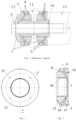
Fig. 1 is an overall structural schematic diagram of an embodiment of the present invention; -
Fig. 2 is a structural schematic diagram of one side of a spherical hinge of an embodiment of the present invention; -
Fig. 3 is a side cross-sectional view; -
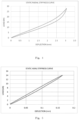
Fig. 4 is a curve chart of radial stiffness of an embodiment of the present invention; and -
Fig. 5 is a curve chart of axial stiffness of an embodiment of the present invention. - The present invention is further described below in combination with the drawings and the specific embodiments.
- As shown in the figure, the present invention relates to a specific use of a method and device for improving the comprehensive performance of an elastic component of an axleless bogie system, mainly applied to a
motor hanger 1 of the Spanish Talgo 350 train. The present invention has the strategies that: according to the structure characteristics of the axleless bogie system of the Spanish Talgo 350 train, multiplefree surfaces 5 of a rubber component are provided in the combination of therubber component 3 and themetallic component 4 of the rubber-metallic elastic compoundedcomponent 2 of themotor hanger 1, stress is released by the multiplefree surfaces 5 of therubber component 3, the stress of the elastic material component is reduced, and thus multidirectional stiffness performance adjustment is performed. - Providing multiple
free surfaces 5 of therubber component 3 in the combination of therubber component 3 and themetal component 4 of the rubber-metal elastic compoundedcomponent 2 refers to adopting three rubberfree surfaces 5 in the rubber-metal elastic compoundedcomponent 2 of the combination of therubber component 3 and themetal component 4 of themotor hanger 1 in the bogie, wherein one free surface is afree surface 6 in the outer diameter direction of the rubber component, the other free surface is afree surface 7 in the inner diameter direction of therubber component 3, and another free surface is afree surface 8 provided in the inclined direction, forming arubber component 3 having free surfaces in three directions. - Rubber-metal elastic compounded
components 2 of themotor hanger 1 are assembled in pairs, and a symmetrical axial pre-pressing combination structure is adopted; themotor hanger 1 is fixed to amotor 10 by a central bolt 9, two rubber-metal elastic compoundedcomponents 2 are adopted by themotor hanger 1, and the two rubber-metal elastic compoundedcomponents 2 are mounted on a bogiecrossbeam mounting seat 11 in a symmetrical axial pre-pressing combination mode by aninner sleeve 16 and apressing sleeve 17, forming a motor hanger; axial symmetrical pre-pressing is realized when the central bolt 9 passes through thepressing sleeve 17 and then is connected and fixed to themotor 10. - Wherein, the
rubber component 3 adopts a suspension segmented Y-shaped rubber structure; one side surface of ametal side ring 12 of themotor hanger 1 is fixed to the bogiecrossbeam mounting seat 11, and the other side surface of themetal side ring 12 is vulcanized together with therubber component 3 through a first surface of the rubber component (3); a second surface of the other surface of therubber component 3 connected to themetal side ring 12 is vulcanized together with the metalinner ring 13, the metalinner ring 13 and therubber component 3 are in an encapsulation structure, and therubber component 3 is always wrapped around theinner metal ring 13 to extend to the inner-diameter inner surface of theinner metal ring 13, forming anencapsulation layer 18; a metalouter ring 14 is arranged in the outer diameter direction in which the metalinner ring 13 is combined with therubber component 3, and the metalouter ring 14 is vulcanized together and comes into contact with further two surfaces of therubber component 3, so that therubber component 3 is formed into arubber component 3 having free surfaces in three directions. - When the
motor hanger 1 is radially loaded, themetal side ring 12 is fixed to the bogiecrossbeam mounting seat 11, the load is acted on the metalinner ring 13 connected with a screw rod (integratedly connected by a metal component), the metalouter ring 14 does not bear, forming a suspended state; meanwhile, rubber between the metalouter ring 14 and themetal side ring 12 is completely in a shearing state (does not provide radial stiffness basically), the radial stiffness is reduced by superposing the three free surfaces of therubber component 3, and during axial loading, because of the effect of compression, the rubber between the metalouter ring 14 and themetal side ring 12 is in a compression state, so that the axial stiffness is substantially increased, the loading performance of the whole motor hanger in all directions is improved, the rubber stress is substantially reduced, and the fatigue life of the motor hanger is prolonged; the radial stiffness curve of the loading and unloading of the motor hanger is shown inFig. 4 ; and the axial stiffness curve of the loading and unloading of the motor hanger is shown inFig. 5 . As shown in the figure, the radial stiffness curve of the loading and unloading of the motor hanger of the present invention is substantially reduced, while the axial stiffness curve of the loading and unloading of the motor hanger is substantially increased. - The
metal side ring 12 of themotor hanger 1 is provided withrubber filling holes 15, and rubber is filled through the rubber filling holes 15 of the metal side ring when manufacturing the rubber component, thereby realizing rubber filling and positioning of the rubber component in a mould during integral vulcanization. The rubber filling holes 15 are four in number, and are uniformly distributed, guaranteeing rubber filling uniformity. - The above described embodiments only clearly and completely describe the technical solution of the present invention in combination with drawings. Apparently, the described embodiments are merely part of the embodiments of the present invention, not all of the embodiments.
- Through the description of the above embodiments, it can be known that the present invention relates to a method for improving the comprehensive performance of an elastic component of an axleless bogie system. According to the structure characteristics of the axleless bogie, multiple free surfaces of the elastic material component are provided in the combination of the elastic component and the elastic material component, stress is released by the multiple free surfaces of the elastic material component, and the stress of the elastic material component of the axleless bogie in all directions is reduced.
- Further, providing multiple free surfaces of the elastic material component refers to respectively providing free surfaces of the elastic material component at different angles and positions in the combination of elastic material component and the metal component according to the stress situation of each component, so that stress can be released by the free surfaces when the elastic material is stressed in all directions, and the stress of the elastic material is reduced.
- Further, the number of the multiple free surfaces of the elastic material component is three or more, and all the free surfaces are at different angles and positions, to guarantee that stress is released when the elastic material component is stressed in multiple directions.
- Further, the number of the multiple free surfaces of the elastic material component is three, wherein one free surface is in the outer diameter direction in which the elastic material is combined with the metal material, the other free surface is in the inner diameter direction in which the elastic material is combined with the metal material, and another free surface is in the inclined direction in which the elastic material is combined with the metal material.
- Further, the free surface in the inclined direction is connected with the free surface in the inner diameter direction to form a spherical elastic material component structure, by combining with the free surface in the outer diameter direction, the entire elastic material component forms a Y-shaped elastic material component, to meet the requirements of high axial stiffness and low radial stiffness of the elastic component of the system with independent wheels.
- Further, the elastic material component is made of rubber material, and the rubber material is compounded with the metal component together by integral vulcanization, forming a rubber-metal elastic compounded component. The rubber material and metal structural component is encapsulated.
- The present invention has the advantages that:
The present invention adopts the concept of multiple free surfaces to design the elastic component into an elastic suspension component with multiple free surfaces, which can substantially reduce the rubber stress and prolong the fatigue life of the elastic suspension component, and has the following advantages: - 1. The present invention can effectively realize stress release in all directions and reduce rubber stress by the design of multiple free surfaces;
- 2. The present invention can realize different stiffness match in four directions by adjusting the structure of each free surface, easily achieve a unique ratio of stiffness match in four directions of radial: axial: deflection: torsional to be 7:100:300:100, and meet the requirements of various loading conditions;
- 3. The elastic component of the present invention adopts a Y-shaped elastic material structural, which is very close to a spherical structure design, and substantially reduces deflection stiffness;
- 4. The elastic component of the present invention internally adopts an encapsulation design to realize self-anti-corrosion and anti-shock in radial direction;
- 5. Applying the principle of the present invention to the motor hanger can fully meet the requirements of Spanish Talgo 350 trains; and
- 6. In the present invention, rubber is filled and vulcanized integrally by means of the rubber filling holes of the metal side ring when manufacturing the rubber component, thereby effectively realizing rubber filling and positioning of the product in a mould.
Claims (5)
- An elastic suspension device for a motor-hanger of an axleless bogie system,- wherein at least one elastic material component (3) is configured to be arranged in the suspension system of the axleless bogie system;- wherein the elastic material component (3) is combined with a metallic component (4) to form an elastic-metallic combination component (2);- exactly three free surfaces (5) are provided for the elastic material component (3) in the elastic-metallic combination component (2), whereby stress release is realized by the multiple free surfaces (5) of the elastic material component (3), therefore, the stress of the elastic material component (3) of the axleless bogie in all directions is reduced, wherein providing multiple free surfaces (5) of the elastic material component (3) refers;- wherein the free surfaces (5) for the elastic material component (3) are designed at different angles and positions in the combination of elastic material component (3) and the metallic component (4) respectively according to the stress conditions of each component, so that stress can be released by the free surfaces (5) when the elastic material component (3) is stressed in all directions, and the stress of the elastic material component (3) is reduced,- wherein the free surfaces (5) are provided in three directions respectively, the first free surface, called the outer free surface (6), being designed in the outer side of diameter direction in which the elastic material is combined to the metal material; the second free surface, called the inner free surface (7), being designed in the inner side of diameter direction in which the elastic material is combined to the metal material; and the third free surface, called the inclined side free surface (8), being designed in the inclined direction in which the elastic material is combined to the metal material; these three free surfaces guaranteeing that stress is released when the elastic material component is stressed in multiple directions;- characterized in that the inclined side free surface (8) is connected to the inner free surface (7) to form a spherical elastic material component structure, this structure being combined to the outer free surface (6), such that the entire elastic material forms a Y-shaped elastic material component, in order to meet the requirements of a very high axial stiffness and low radial stiffness of the elastic component of the system with independent wheels at the same time.
- The elastic suspension device for a motor-hanger of an axleless bogie system according to claim 1, characterized in that the elastic material component (3) is made of rubber material, and the rubber material is compounded with the metallic component (4) together by integral vulcanization, forming a rubber-metal elastic compounded component (2), wherein the rubber material and metallic component (4) is encapsulated.
- The elastic suspension device for a motor-hanger of an axleless bogie system according to claim 1, characterized in that the metallic component (4) includes a metal side ring (12), a metal inner ring (13) and a metal outer ring (14), wherein one side surface of the metal side ring (12) of the elastic suspension device for the motor hanger (1) is configured to be fixed to the bogie crossbeam mounting seat (11), and the other side surface of the metal side ring (12) is vulcanized together with the rubber component (3) through a first surface of the rubber component (3); a second surface of the rubber component (3) connected to the metal side ring (12) is vulcanized together with the metal inner ring (13), the metal inner ring (13) and the rubber component (3) are in an encapsulation structure, and the rubber component (3) is always wrapped around the inner metal ring (13) to extend to the inner-diameter inner surface of the inner metal ring (13), forming an encapsulation layer (18); the metal outer ring (14) is arranged in the outer diameter direction in which the metal inner ring (13) is combined with the rubber component (3), and the metal outer ring (14) is vulcanized together and comes into contact with further two surfaces of the rubber component (3), so that the rubber component (3) is formed into a rubber component (3) having free surfaces in three directions..
- The elastic suspension device for a motor-hanger of an axleless bogie system according to claim 3, characterized in that the metal side ring (12) is provided with rubber filling holes (15).
- The elastic suspension device for a motor-hanger of an axleless bogie system according to claim 3, characterized in that there are four rubber filling holes (15) are uniformly distributed on the metal side ring (12).
Applications Claiming Priority (1)
| Application Number | Priority Date | Filing Date | Title |
|---|---|---|---|
| CN201811168266.1A CN109229131A (en) | 2018-10-08 | 2018-10-08 | Without wheel axle bogie system resilience component synthesis performance improvement method and device |
Publications (3)
| Publication Number | Publication Date |
|---|---|
| EP3636510A1 EP3636510A1 (en) | 2020-04-15 |
| EP3636510C0 EP3636510C0 (en) | 2025-04-02 |
| EP3636510B1 true EP3636510B1 (en) | 2025-04-02 |
Family
ID=65055180
Family Applications (1)
| Application Number | Title | Priority Date | Filing Date |
|---|---|---|---|
| EP19200485.1A Active EP3636510B1 (en) | 2018-10-08 | 2019-09-30 | Device for improving comprehensive performance of elastic component of axleless bogie system |
Country Status (2)
| Country | Link |
|---|---|
| EP (1) | EP3636510B1 (en) |
| CN (1) | CN109229131A (en) |
Families Citing this family (2)
| Publication number | Priority date | Publication date | Assignee | Title |
|---|---|---|---|---|
| CN110065778B (en) * | 2019-05-27 | 2024-05-03 | 大连华锐重工焦炉车辆设备有限公司 | Rotary traveling mechanism of fixed-arm fan-shaped stacker |
| WO2024219394A1 (en) * | 2023-04-17 | 2024-10-24 | パナソニックIpマネジメント株式会社 | Rotating body attachment structure and projection video display device |
Citations (1)
| Publication number | Priority date | Publication date | Assignee | Title |
|---|---|---|---|---|
| EP0332903A2 (en) * | 1988-03-17 | 1989-09-20 | Metzeler Gimetall Ag | Hydraulically damped dual-chamber engine mount |
Family Cites Families (9)
| Publication number | Priority date | Publication date | Assignee | Title |
|---|---|---|---|---|
| CH331740A (en) * | 1955-07-22 | 1958-07-31 | Inventio Ag | Motor bogie for rail vehicles |
| JP2776463B2 (en) * | 1986-07-08 | 1998-07-16 | 株式会社ブリヂストン | Anti-vibration device |
| CN103129400B (en) * | 2011-11-26 | 2015-01-21 | 南车青岛四方机车车辆股份有限公司 | Car roof power receiving system vibration-reduction connecting device and method thereof |
| CN102865324B (en) * | 2012-10-22 | 2014-04-16 | 株洲时代新材料科技股份有限公司 | Processing method of wailway vehicle tumbler location device |
| CN103112466B (en) * | 2013-02-22 | 2015-11-18 | 包头北方创业股份有限公司 | Rail vehicle truck |
| CN108146453A (en) * | 2016-12-05 | 2018-06-12 | 中车大同电力机车有限公司 | A kind of low-floor tramcar bogie driving unit |
| CN108343700B (en) * | 2017-01-23 | 2020-09-22 | 株洲时代瑞唯减振装备有限公司 | Hydraulic bushing |
| RU176873U1 (en) * | 2017-06-13 | 2018-01-31 | ФЕДЕРАЛЬНОЕ ГОСУДАРСТВЕННОЕ БЮДЖЕТНОЕ ОБРАЗОВАТЕЛЬНОЕ УЧРЕЖДЕНИЕ ВЫСШЕГО ОБРАЗОВАНИЯ "Брянский государственный технический университет" | Traction motor suspension unit |
| CN108438010B (en) * | 2017-12-27 | 2020-10-27 | 株洲时代瑞唯减振装备有限公司 | Method for preventing rotating arm node of high-speed motor train unit from axially shifting |
-
2018
- 2018-10-08 CN CN201811168266.1A patent/CN109229131A/en active Pending
-
2019
- 2019-09-30 EP EP19200485.1A patent/EP3636510B1/en active Active
Patent Citations (1)
| Publication number | Priority date | Publication date | Assignee | Title |
|---|---|---|---|---|
| EP0332903A2 (en) * | 1988-03-17 | 1989-09-20 | Metzeler Gimetall Ag | Hydraulically damped dual-chamber engine mount |
Also Published As
| Publication number | Publication date |
|---|---|
| EP3636510C0 (en) | 2025-04-02 |
| EP3636510A1 (en) | 2020-04-15 |
| CN109229131A (en) | 2019-01-18 |
Similar Documents
| Publication | Publication Date | Title |
|---|---|---|
| CN103786739B (en) | Low-power radial welding bogie | |
| US2908230A (en) | Railway car truck | |
| AU2013269634B2 (en) | Rail vehicle unit | |
| CN107107921B (en) | Cross member for rail car for linking car body of rail car and bogie thereof | |
| CN111994108B (en) | Axle box guide post positioning type three-axle welded self-steering radial railway freight car bogie | |
| CN103661463B (en) | A kind of bogie for high-speed rail wagon | |
| EP3369640A1 (en) | Method for improving overall performance of rail vehicle bogie and suspension damping system | |
| CN110979376B (en) | Rigidity adjusting method and structure of primary suspension device | |
| Orlova et al. | The anatomy of railway vehicle running gear | |
| CN107585174B (en) | Low torsional rigidity bogie and rail vehicle | |
| CN107776602B (en) | Method and structure for changing rigidity of axle box positioning node by adjusting rubber layer parameters | |
| CN105216821A (en) | A kind of passenger car bogie | |
| CN111071278B (en) | Method and structure for adjusting vertical rigidity of primary suspension device | |
| EP4086136A1 (en) | Bolster-less framed bogie suitable for high-speed freight wagon | |
| CN112026824A (en) | Axle box positioning method, axle box overhead node and railway vehicle | |
| CN205440380U (en) | Narrow gauge steel spring coach bogie | |
| EP3636510A1 (en) | Method and device for improving comprehensive performance of elastic component of axleless bogie system | |
| US3720175A (en) | Resiliently mounted railway vehicle truck | |
| CN203593001U (en) | High-speed railway wagon bogie | |
| WO2023138584A1 (en) | Railway freight wagon bogie having high dynamic performance | |
| EP3636950B1 (en) | Method for increasing axial stiffness, reducing radial and deflection stiffness of elastic compounded component | |
| JP2000502306A (en) | Rail vehicles | |
| CN111532304B (en) | Connecting method and device for applying plate type variable-rigidity composite joint to light-weight coupler | |
| CN116476884A (en) | Primary rubber spring for metro vehicle | |
| CN204956500U (en) | Coach bogie |
Legal Events
| Date | Code | Title | Description |
|---|---|---|---|
| PUAI | Public reference made under article 153(3) epc to a published international application that has entered the european phase |
Free format text: ORIGINAL CODE: 0009012 |
|
| STAA | Information on the status of an ep patent application or granted ep patent |
Free format text: STATUS: THE APPLICATION HAS BEEN PUBLISHED |
|
| AK | Designated contracting states |
Kind code of ref document: A1 Designated state(s): AL AT BE BG CH CY CZ DE DK EE ES FI FR GB GR HR HU IE IS IT LI LT LU LV MC MK MT NL NO PL PT RO RS SE SI SK SM TR |
|
| AX | Request for extension of the european patent |
Extension state: BA ME |
|
| STAA | Information on the status of an ep patent application or granted ep patent |
Free format text: STATUS: REQUEST FOR EXAMINATION WAS MADE |
|
| 17P | Request for examination filed |
Effective date: 20201008 |
|
| RBV | Designated contracting states (corrected) |
Designated state(s): AL AT BE BG CH CY CZ DE DK EE ES FI FR GB GR HR HU IE IS IT LI LT LU LV MC MK MT NL NO PL PT RO RS SE SI SK SM TR |
|
| STAA | Information on the status of an ep patent application or granted ep patent |
Free format text: STATUS: EXAMINATION IS IN PROGRESS |
|
| 17Q | First examination report despatched |
Effective date: 20220218 |
|
| GRAP | Despatch of communication of intention to grant a patent |
Free format text: ORIGINAL CODE: EPIDOSNIGR1 |
|
| STAA | Information on the status of an ep patent application or granted ep patent |
Free format text: STATUS: GRANT OF PATENT IS INTENDED |
|
| INTG | Intention to grant announced |
Effective date: 20241223 |
|
| GRAS | Grant fee paid |
Free format text: ORIGINAL CODE: EPIDOSNIGR3 |
|
| GRAA | (expected) grant |
Free format text: ORIGINAL CODE: 0009210 |
|
| STAA | Information on the status of an ep patent application or granted ep patent |
Free format text: STATUS: THE PATENT HAS BEEN GRANTED |
|
| AK | Designated contracting states |
Kind code of ref document: B1 Designated state(s): AL AT BE BG CH CY CZ DE DK EE ES FI FR GB GR HR HU IE IS IT LI LT LU LV MC MK MT NL NO PL PT RO RS SE SI SK SM TR |
|
| REG | Reference to a national code |
Ref country code: GB Ref legal event code: FG4D |
|
| REG | Reference to a national code |
Ref country code: CH Ref legal event code: EP |
|
| REG | Reference to a national code |
Ref country code: IE Ref legal event code: FG4D |
|
| REG | Reference to a national code |
Ref country code: DE Ref legal event code: R096 Ref document number: 602019068022 Country of ref document: DE |
|
| U01 | Request for unitary effect filed |
Effective date: 20250422 |
|
| U07 | Unitary effect registered |
Designated state(s): AT BE BG DE DK EE FI FR IT LT LU LV MT NL PT RO SE SI Effective date: 20250428 |
|
| U20 | Renewal fee for the european patent with unitary effect paid |
Year of fee payment: 7 Effective date: 20250703 |
|
| PG25 | Lapsed in a contracting state [announced via postgrant information from national office to epo] |
Ref country code: ES Free format text: LAPSE BECAUSE OF FAILURE TO SUBMIT A TRANSLATION OF THE DESCRIPTION OR TO PAY THE FEE WITHIN THE PRESCRIBED TIME-LIMIT Effective date: 20250402 |
|
| PG25 | Lapsed in a contracting state [announced via postgrant information from national office to epo] |
Ref country code: GR Free format text: LAPSE BECAUSE OF FAILURE TO SUBMIT A TRANSLATION OF THE DESCRIPTION OR TO PAY THE FEE WITHIN THE PRESCRIBED TIME-LIMIT Effective date: 20250703 Ref country code: NO Free format text: LAPSE BECAUSE OF FAILURE TO SUBMIT A TRANSLATION OF THE DESCRIPTION OR TO PAY THE FEE WITHIN THE PRESCRIBED TIME-LIMIT Effective date: 20250702 |
|
| PG25 | Lapsed in a contracting state [announced via postgrant information from national office to epo] |
Ref country code: PL Free format text: LAPSE BECAUSE OF FAILURE TO SUBMIT A TRANSLATION OF THE DESCRIPTION OR TO PAY THE FEE WITHIN THE PRESCRIBED TIME-LIMIT Effective date: 20250402 |
|
| PG25 | Lapsed in a contracting state [announced via postgrant information from national office to epo] |
Ref country code: HR Free format text: LAPSE BECAUSE OF FAILURE TO SUBMIT A TRANSLATION OF THE DESCRIPTION OR TO PAY THE FEE WITHIN THE PRESCRIBED TIME-LIMIT Effective date: 20250402 |
|
| PG25 | Lapsed in a contracting state [announced via postgrant information from national office to epo] |
Ref country code: RS Free format text: LAPSE BECAUSE OF FAILURE TO SUBMIT A TRANSLATION OF THE DESCRIPTION OR TO PAY THE FEE WITHIN THE PRESCRIBED TIME-LIMIT Effective date: 20250702 |
|
| PG25 | Lapsed in a contracting state [announced via postgrant information from national office to epo] |
Ref country code: IS Free format text: LAPSE BECAUSE OF FAILURE TO SUBMIT A TRANSLATION OF THE DESCRIPTION OR TO PAY THE FEE WITHIN THE PRESCRIBED TIME-LIMIT Effective date: 20250802 |
|
| PG25 | Lapsed in a contracting state [announced via postgrant information from national office to epo] |
Ref country code: SM Free format text: LAPSE BECAUSE OF FAILURE TO SUBMIT A TRANSLATION OF THE DESCRIPTION OR TO PAY THE FEE WITHIN THE PRESCRIBED TIME-LIMIT Effective date: 20250402 |
|
| PG25 | Lapsed in a contracting state [announced via postgrant information from national office to epo] |
Ref country code: CZ Free format text: LAPSE BECAUSE OF FAILURE TO SUBMIT A TRANSLATION OF THE DESCRIPTION OR TO PAY THE FEE WITHIN THE PRESCRIBED TIME-LIMIT Effective date: 20250402 |
|
| PG25 | Lapsed in a contracting state [announced via postgrant information from national office to epo] |
Ref country code: SK Free format text: LAPSE BECAUSE OF FAILURE TO SUBMIT A TRANSLATION OF THE DESCRIPTION OR TO PAY THE FEE WITHIN THE PRESCRIBED TIME-LIMIT Effective date: 20250402 |
|
| PLBE | No opposition filed within time limit |
Free format text: ORIGINAL CODE: 0009261 |
|
| STAA | Information on the status of an ep patent application or granted ep patent |
Free format text: STATUS: NO OPPOSITION FILED WITHIN TIME LIMIT |
|
| REG | Reference to a national code |
Ref country code: CH Ref legal event code: L10 Free format text: ST27 STATUS EVENT CODE: U-0-0-L10-L00 (AS PROVIDED BY THE NATIONAL OFFICE) Effective date: 20260211 |
|
| 26N | No opposition filed |
Effective date: 20260105 |
|
| REG | Reference to a national code |
Ref country code: CH Ref legal event code: H13 Free format text: ST27 STATUS EVENT CODE: U-0-0-H10-H13 (AS PROVIDED BY THE NATIONAL OFFICE) Effective date: 20260504 |