EP3636407B1 - Seal profile holder comprising a first and a second holding unit - Google Patents
Seal profile holder comprising a first and a second holding unit Download PDFInfo
- Publication number
- EP3636407B1 EP3636407B1 EP18199720.6A EP18199720A EP3636407B1 EP 3636407 B1 EP3636407 B1 EP 3636407B1 EP 18199720 A EP18199720 A EP 18199720A EP 3636407 B1 EP3636407 B1 EP 3636407B1
- Authority
- EP
- European Patent Office
- Prior art keywords
- unit
- drive
- chain
- guide
- holding
- Prior art date
- Legal status (The legal status is an assumption and is not a legal conclusion. Google has not performed a legal analysis and makes no representation as to the accuracy of the status listed.)
- Active
Links
- 238000007789 sealing Methods 0.000 claims description 37
- 238000001746 injection moulding Methods 0.000 claims description 19
- 238000005266 casting Methods 0.000 claims description 18
- 239000004033 plastic Substances 0.000 claims description 9
- 229920003023 plastic Polymers 0.000 claims description 9
- 238000001816 cooling Methods 0.000 claims description 4
- 238000010438 heat treatment Methods 0.000 claims description 3
- 238000002347 injection Methods 0.000 description 9
- 239000007924 injection Substances 0.000 description 9
- 238000004519 manufacturing process Methods 0.000 description 6
- 238000000034 method Methods 0.000 description 6
- 230000008569 process Effects 0.000 description 6
- 238000012545 processing Methods 0.000 description 5
- 230000008859 change Effects 0.000 description 4
- 238000011161 development Methods 0.000 description 4
- 230000018109 developmental process Effects 0.000 description 4
- 208000027418 Wounds and injury Diseases 0.000 description 3
- 230000008901 benefit Effects 0.000 description 3
- 230000006378 damage Effects 0.000 description 3
- 238000013461 design Methods 0.000 description 3
- 229920001971 elastomer Polymers 0.000 description 3
- 208000014674 injury Diseases 0.000 description 3
- 238000005461 lubrication Methods 0.000 description 3
- 229920002725 thermoplastic elastomer Polymers 0.000 description 3
- 229920002943 EPDM rubber Polymers 0.000 description 2
- 238000005299 abrasion Methods 0.000 description 2
- 230000006978 adaptation Effects 0.000 description 2
- 230000009977 dual effect Effects 0.000 description 2
- 238000009413 insulation Methods 0.000 description 2
- 238000003754 machining Methods 0.000 description 2
- 239000002184 metal Substances 0.000 description 2
- 239000005060 rubber Substances 0.000 description 2
- 230000001360 synchronised effect Effects 0.000 description 2
- 240000004752 Laburnum anagyroides Species 0.000 description 1
- 238000010276 construction Methods 0.000 description 1
- 230000000694 effects Effects 0.000 description 1
- 239000000806 elastomer Substances 0.000 description 1
- 230000002349 favourable effect Effects 0.000 description 1
- 230000009969 flowable effect Effects 0.000 description 1
- 230000005484 gravity Effects 0.000 description 1
- 238000003780 insertion Methods 0.000 description 1
- 230000037431 insertion Effects 0.000 description 1
- 239000007788 liquid Substances 0.000 description 1
- 238000012423 maintenance Methods 0.000 description 1
- 230000007246 mechanism Effects 0.000 description 1
- 238000003801 milling Methods 0.000 description 1
- 238000000465 moulding Methods 0.000 description 1
- 239000003921 oil Substances 0.000 description 1
- WXZMFSXDPGVJKK-UHFFFAOYSA-N pentaerythritol Chemical compound OCC(CO)(CO)CO WXZMFSXDPGVJKK-UHFFFAOYSA-N 0.000 description 1
- 239000005020 polyethylene terephthalate Substances 0.000 description 1
- 229920000139 polyethylene terephthalate Polymers 0.000 description 1
- 230000009467 reduction Effects 0.000 description 1
- 239000007779 soft material Substances 0.000 description 1
- 125000006850 spacer group Chemical group 0.000 description 1
- 230000002459 sustained effect Effects 0.000 description 1
- 229920001169 thermoplastic Polymers 0.000 description 1
- 239000004416 thermosoftening plastic Substances 0.000 description 1
Images


Classifications
-
- B—PERFORMING OPERATIONS; TRANSPORTING
- B29—WORKING OF PLASTICS; WORKING OF SUBSTANCES IN A PLASTIC STATE IN GENERAL
- B29C—SHAPING OR JOINING OF PLASTICS; SHAPING OF MATERIAL IN A PLASTIC STATE, NOT OTHERWISE PROVIDED FOR; AFTER-TREATMENT OF THE SHAPED PRODUCTS, e.g. REPAIRING
- B29C45/00—Injection moulding, i.e. forcing the required volume of moulding material through a nozzle into a closed mould; Apparatus therefor
- B29C45/14—Injection moulding, i.e. forcing the required volume of moulding material through a nozzle into a closed mould; Apparatus therefor incorporating preformed parts or layers, e.g. injection moulding around inserts or for coating articles
- B29C45/14008—Inserting articles into the mould
-
- B—PERFORMING OPERATIONS; TRANSPORTING
- B29—WORKING OF PLASTICS; WORKING OF SUBSTANCES IN A PLASTIC STATE IN GENERAL
- B29C—SHAPING OR JOINING OF PLASTICS; SHAPING OF MATERIAL IN A PLASTIC STATE, NOT OTHERWISE PROVIDED FOR; AFTER-TREATMENT OF THE SHAPED PRODUCTS, e.g. REPAIRING
- B29C65/00—Joining or sealing of preformed parts, e.g. welding of plastics materials; Apparatus therefor
- B29C65/78—Means for handling the parts to be joined, e.g. for making containers or hollow articles, e.g. means for handling sheets, plates, web-like materials, tubular articles, hollow articles or elements to be joined therewith; Means for discharging the joined articles from the joining apparatus
- B29C65/7841—Holding or clamping means for handling purposes
-
- B—PERFORMING OPERATIONS; TRANSPORTING
- B29—WORKING OF PLASTICS; WORKING OF SUBSTANCES IN A PLASTIC STATE IN GENERAL
- B29C—SHAPING OR JOINING OF PLASTICS; SHAPING OF MATERIAL IN A PLASTIC STATE, NOT OTHERWISE PROVIDED FOR; AFTER-TREATMENT OF THE SHAPED PRODUCTS, e.g. REPAIRING
- B29C45/00—Injection moulding, i.e. forcing the required volume of moulding material through a nozzle into a closed mould; Apparatus therefor
- B29C45/0053—Injection moulding, i.e. forcing the required volume of moulding material through a nozzle into a closed mould; Apparatus therefor combined with a final operation, e.g. shaping
- B29C45/006—Joining parts moulded in separate cavities
-
- B—PERFORMING OPERATIONS; TRANSPORTING
- B29—WORKING OF PLASTICS; WORKING OF SUBSTANCES IN A PLASTIC STATE IN GENERAL
- B29C—SHAPING OR JOINING OF PLASTICS; SHAPING OF MATERIAL IN A PLASTIC STATE, NOT OTHERWISE PROVIDED FOR; AFTER-TREATMENT OF THE SHAPED PRODUCTS, e.g. REPAIRING
- B29C45/00—Injection moulding, i.e. forcing the required volume of moulding material through a nozzle into a closed mould; Apparatus therefor
- B29C45/14—Injection moulding, i.e. forcing the required volume of moulding material through a nozzle into a closed mould; Apparatus therefor incorporating preformed parts or layers, e.g. injection moulding around inserts or for coating articles
- B29C45/14065—Positioning or centering articles in the mould
-
- B—PERFORMING OPERATIONS; TRANSPORTING
- B29—WORKING OF PLASTICS; WORKING OF SUBSTANCES IN A PLASTIC STATE IN GENERAL
- B29C—SHAPING OR JOINING OF PLASTICS; SHAPING OF MATERIAL IN A PLASTIC STATE, NOT OTHERWISE PROVIDED FOR; AFTER-TREATMENT OF THE SHAPED PRODUCTS, e.g. REPAIRING
- B29C45/00—Injection moulding, i.e. forcing the required volume of moulding material through a nozzle into a closed mould; Apparatus therefor
- B29C45/14—Injection moulding, i.e. forcing the required volume of moulding material through a nozzle into a closed mould; Apparatus therefor incorporating preformed parts or layers, e.g. injection moulding around inserts or for coating articles
- B29C45/14336—Coating a portion of the article, e.g. the edge of the article
- B29C45/14409—Coating profiles or strips by injecting end or corner or intermediate parts
-
- B—PERFORMING OPERATIONS; TRANSPORTING
- B29—WORKING OF PLASTICS; WORKING OF SUBSTANCES IN A PLASTIC STATE IN GENERAL
- B29C—SHAPING OR JOINING OF PLASTICS; SHAPING OF MATERIAL IN A PLASTIC STATE, NOT OTHERWISE PROVIDED FOR; AFTER-TREATMENT OF THE SHAPED PRODUCTS, e.g. REPAIRING
- B29C45/00—Injection moulding, i.e. forcing the required volume of moulding material through a nozzle into a closed mould; Apparatus therefor
- B29C45/14—Injection moulding, i.e. forcing the required volume of moulding material through a nozzle into a closed mould; Apparatus therefor incorporating preformed parts or layers, e.g. injection moulding around inserts or for coating articles
- B29C45/14467—Joining articles or parts of a single article
-
- B—PERFORMING OPERATIONS; TRANSPORTING
- B29—WORKING OF PLASTICS; WORKING OF SUBSTANCES IN A PLASTIC STATE IN GENERAL
- B29C—SHAPING OR JOINING OF PLASTICS; SHAPING OF MATERIAL IN A PLASTIC STATE, NOT OTHERWISE PROVIDED FOR; AFTER-TREATMENT OF THE SHAPED PRODUCTS, e.g. REPAIRING
- B29C45/00—Injection moulding, i.e. forcing the required volume of moulding material through a nozzle into a closed mould; Apparatus therefor
- B29C45/17—Component parts, details or accessories; Auxiliary operations
- B29C45/26—Moulds
- B29C45/33—Moulds having transversely, e.g. radially, movable mould parts
- B29C45/332—Mountings or guides therefor; Drives therefor
-
- B—PERFORMING OPERATIONS; TRANSPORTING
- B29—WORKING OF PLASTICS; WORKING OF SUBSTANCES IN A PLASTIC STATE IN GENERAL
- B29C—SHAPING OR JOINING OF PLASTICS; SHAPING OF MATERIAL IN A PLASTIC STATE, NOT OTHERWISE PROVIDED FOR; AFTER-TREATMENT OF THE SHAPED PRODUCTS, e.g. REPAIRING
- B29C45/00—Injection moulding, i.e. forcing the required volume of moulding material through a nozzle into a closed mould; Apparatus therefor
- B29C45/17—Component parts, details or accessories; Auxiliary operations
- B29C45/40—Removing or ejecting moulded articles
- B29C45/4005—Ejector constructions; Ejector operating mechanisms
-
- F—MECHANICAL ENGINEERING; LIGHTING; HEATING; WEAPONS; BLASTING
- F16—ENGINEERING ELEMENTS AND UNITS; GENERAL MEASURES FOR PRODUCING AND MAINTAINING EFFECTIVE FUNCTIONING OF MACHINES OR INSTALLATIONS; THERMAL INSULATION IN GENERAL
- F16G—BELTS, CABLES, OR ROPES, PREDOMINANTLY USED FOR DRIVING PURPOSES; CHAINS; FITTINGS PREDOMINANTLY USED THEREFOR
- F16G13/00—Chains
- F16G13/02—Driving-chains
- F16G13/06—Driving-chains with links connected by parallel driving-pins with or without rollers so called open links
-
- F—MECHANICAL ENGINEERING; LIGHTING; HEATING; WEAPONS; BLASTING
- F16—ENGINEERING ELEMENTS AND UNITS; GENERAL MEASURES FOR PRODUCING AND MAINTAINING EFFECTIVE FUNCTIONING OF MACHINES OR INSTALLATIONS; THERMAL INSULATION IN GENERAL
- F16H—GEARING
- F16H19/00—Gearings comprising essentially only toothed gears or friction members and not capable of conveying indefinitely-continuing rotary motion
- F16H19/02—Gearings comprising essentially only toothed gears or friction members and not capable of conveying indefinitely-continuing rotary motion for interconverting rotary or oscillating motion and reciprocating motion
- F16H19/06—Gearings comprising essentially only toothed gears or friction members and not capable of conveying indefinitely-continuing rotary motion for interconverting rotary or oscillating motion and reciprocating motion comprising flexible members, e.g. an endless flexible member
-
- B—PERFORMING OPERATIONS; TRANSPORTING
- B29—WORKING OF PLASTICS; WORKING OF SUBSTANCES IN A PLASTIC STATE IN GENERAL
- B29C—SHAPING OR JOINING OF PLASTICS; SHAPING OF MATERIAL IN A PLASTIC STATE, NOT OTHERWISE PROVIDED FOR; AFTER-TREATMENT OF THE SHAPED PRODUCTS, e.g. REPAIRING
- B29C45/00—Injection moulding, i.e. forcing the required volume of moulding material through a nozzle into a closed mould; Apparatus therefor
- B29C45/14—Injection moulding, i.e. forcing the required volume of moulding material through a nozzle into a closed mould; Apparatus therefor incorporating preformed parts or layers, e.g. injection moulding around inserts or for coating articles
- B29C45/14467—Joining articles or parts of a single article
- B29C2045/1454—Joining articles or parts of a single article injecting between inserts not being in contact with each other
-
- B—PERFORMING OPERATIONS; TRANSPORTING
- B29—WORKING OF PLASTICS; WORKING OF SUBSTANCES IN A PLASTIC STATE IN GENERAL
- B29L—INDEXING SCHEME ASSOCIATED WITH SUBCLASS B29C, RELATING TO PARTICULAR ARTICLES
- B29L2031/00—Other particular articles
- B29L2031/26—Sealing devices, e.g. packaging for pistons or pipe joints
- B29L2031/265—Packings, Gaskets
-
- F—MECHANICAL ENGINEERING; LIGHTING; HEATING; WEAPONS; BLASTING
- F16—ENGINEERING ELEMENTS AND UNITS; GENERAL MEASURES FOR PRODUCING AND MAINTAINING EFFECTIVE FUNCTIONING OF MACHINES OR INSTALLATIONS; THERMAL INSULATION IN GENERAL
- F16H—GEARING
- F16H19/00—Gearings comprising essentially only toothed gears or friction members and not capable of conveying indefinitely-continuing rotary motion
- F16H19/02—Gearings comprising essentially only toothed gears or friction members and not capable of conveying indefinitely-continuing rotary motion for interconverting rotary or oscillating motion and reciprocating motion
- F16H19/06—Gearings comprising essentially only toothed gears or friction members and not capable of conveying indefinitely-continuing rotary motion for interconverting rotary or oscillating motion and reciprocating motion comprising flexible members, e.g. an endless flexible member
- F16H19/0645—Gearings comprising essentially only toothed gears or friction members and not capable of conveying indefinitely-continuing rotary motion for interconverting rotary or oscillating motion and reciprocating motion comprising flexible members, e.g. an endless flexible member the flexible push or pull member having guiding means, i.e. the flexible member being supported at least partially by a guide to transmit the reciprocating movement
Definitions
- the invention relates to a sealing profile receiving device with at least one first holding unit for receiving and holding a first sealing profile element and with a second holding unit for receiving and holding a second sealing profile element and with at least one casting unit for casting at least one connecting section for connecting the first sealing profile element to the second Sealing profile element and / or for casting a first end termination of the first sealing profile element and a second end termination of the second sealing profile element according to the preamble of claim 1.
- profiles or profile parts are comparatively long and thin and essentially consist of elastic, soft material with a high coefficient of friction such as thermoplastic elastomer (TPE) or rubbers or rubbers, e.g. EPDM, TPO, TPU, PP, PPE, PIB, PS, PETP, POM, TPU or the like. Therefore, these profiles must be introduced into the receiving devices or holders / molds with a large amount of play or air, and for casting, the molds or holders have to lie very tightly or be clamped and removed again with a large amount of play or air.
- the mountings are usually designed in at least two parts, with at least one component or one element being adjustable relative to the other.
- the finished profiles often have to be thrown out of the mold / holder in order to remove them, so that a new profile can then be produced with the receiving device.
- the complexity of the mounting devices also means that, among other things, the arrangement or use of the drives suffers from a lack of space. Thus, deflections or changes of direction between the so-called drive and the so-called output of 90 °, 135 ° etc. are often necessary in order to get to the element / molded part to be adjusted. Safety regulations for free, safe access and manual operation by the operator must also be observed.
- thermoplastics and elastomers When processing thermoplastics and elastomers, working temperatures of up to approx. 200 ° C. are common, so that the receiving device or corresponding components have to be partially heated and / or cooled. As a result, high thermal requirements are also placed on the drives and adjustable components.
- a sealing profile receiving device is characterized in that the first and / or second and / or third drive unit has at least one chain comprising several chain links, the chain and / or chain links at least between two guide surfaces of a guide unit for guiding the chain and / or chain links is arranged so that an adjusting force can be implemented with the chain drive both in the pulling direction and in the pushing direction of the chain.
- the drive (s) can be adapted very flexibly to the most varied of requirements and available space, since the guide or the guide surfaces, along which the adjustable chains / chain links are guided, can be made in a wide variety of designs without great effort. Forms can be formed / manufactured. With the guided chain according to the invention, both tensile forces and compressive forces can be generated on the element to be adjusted, so that force can advantageously be applied to them in two opposite directions. This enables an advantageous opening and closing of the Holding units and / or ejectors etc. in a particularly compact design.
- the compact drives or drive units for the individual sealing profile receiving devices can be standardized, although the drives have to be adapted to the most varied of framework conditions, such as space, few positioning options versus free space for the operator, etc., alignment with the element to be adjusted, Length of the adjustment paths, different adjustment paths or sections such as, for example, rotary and / or pivoting movement and / or cam track and / or linear movement.
- framework conditions such as space, few positioning options versus free space for the operator, etc.
- Length of the adjustment paths such as space, few positioning options versus free space for the operator, etc., alignment with the element to be adjusted
- Length of the adjustment paths different adjustment paths or sections such as, for example, rotary and / or pivoting movement and / or cam track and / or linear movement.
- different drives had to be developed up to now. This led to high development and manufacturing costs corresponding to individual sealing profile receiving devices.
- a standardization of the drive or the essential components of the drive units according to the invention for sealing profile receiving devices has
- a linear movement of the adjustable holding element and / or the ejector is preferably implemented.
- cam track adjustments of the adjustable holding element and / or the ejector can also be implemented in an advantageous manner.
- an increasing automation of the sealing profile receiving devices can also be achieved.
- Drives or drive units can also be used instead of the previously customary manual drives or handles. This makes it possible to reduce the physical strain on the operator, which makes the certain manual operation that is currently still necessary or the person over an entire working day with sometimes hundreds of sealing profiles to be produced more productive.
- a faster, more controlled and less error-free production is usually achieved, at least for the adjustments or work steps in which no intermediate steps and / or complex cam paths need to be implemented.
- Increasing automation also ensures a significant reduction in the risk of injury to the operator, ie fewer manual manipulations or interventions reduces the risk that the person's fingers or hands could be pinched or squeezed and serious injuries could be sustained.
- the first and / or second and / or third drive unit advantageously comprises at least one linear drive for linear adjustment of a first drive element.
- the linear drive can be designed as a linear motor or the first drive element of the linear drive can be designed as a rack or threaded rod.
- the linear drive is preferably designed as a stroke-piston-cylinder unit, the first drive element being designed as an adjustable piston.
- the chain and / or chain links are arranged between the first drive element and a second drive element.
- the second drive element can advantageously realize a linear movement.
- rotary and / or pivoting movements, rotations, (arcuate / wave-shaped) cam path adjustments of the second drive element or the so-called drive element can also be implemented.
- the first drive element can be adjusted in a first adjustment direction and the second drive element can be adjusted in a second adjustment direction, the first adjustment direction being angled, in particular perpendicular, to the second adjustment direction.
- an advantageous deflection or change of direction between the first drive element and the second drive element can be achieved.
- almost any deflection of e.g. approx. 30 °, 45 °, 90 °, 110 °, 135 ° or 160 ° etc. can be implemented.
- This means that an almost free or arbitrary choice of angle can be achieved, so that an advantageous adaptation or flexibility to the narrow and / or predetermined geometrical relationships of the receiving device can be achieved.
- a corresponding angle adjustment can only be achieved by designing the guide unit accordingly, i.e. according to the space / space conditions specified by other components.
- Chain / chain links, first and second drive elements as well as drive devices such as stroke-piston-cylinder units or the like do not need to be adapted / changed according to the invention or only need to be adapted / changed to a minimal extent, e.g. chains of different lengths due to different numbers of (standardized) chain links.
- the manufacturer of sealing profile receiving devices with regard to these essential components of the drive unit according to the invention can produce comparatively large numbers of items, which considerably reduces the expenditure for development and construction and thus also the economic expenditure.
- the guide unit preferably comprises at least one guide groove and / or guide recess.
- a guide element comprises the guide groove and / or guide recess, advantageously a cover element / plate or the like is provided. In this way, an advantageous closed guidance of the chain or chain links can be realized. This is positive in terms of operational safety and precise guidance.
- An adaptation or change in the alignment of the drive or the second adjustment direction of the second drive element can only be implemented by changing the shape of the guide groove and / or guide recess accordingly, in particular a housing and / or an outer shape and / or further elements of the guide unit can remain almost unchanged.
- the guide groove and / or guide recess can advantageously be generated by means of machining manufacturing processes such as milling or the like. This is inexpensive and can be implemented in any form, e.g. with modern CNC machine tools, without great effort.
- the guide unit advantageously comprises at least one curved and / or round guide section for deflecting the chain and / or chain links. In this way, the deflection or change of direction between the first drive element and the second drive element can be implemented in an advantageous manner.
- the guide unit can comprise at least one deflection wheel rotatable about an axis of rotation for deflecting the chain and / or chain links.
- This allows the chain or chain links to be advantageously guided in the guide unit.
- An advantageous rotary movement or rotation of the second drive element can also be achieved. This means that, for example, a linear drive or a linear adjustment of the first drive element by means of the chain or chain links according to the invention in a Rotation of the second drive element can be transformed in an advantageous manner.
- At least two chains are fixed to the first drive element of the linear drive, so that when the first drive element is adjusted, the at least two chains are adjusted at the same time.
- a single or common drive can be used for e.g. two or four different adjustable elements such as holding elements, ejectors or the like.
- This dual use of a drive such as a pneumatic or hydraulic stroke-piston-cylinder drive reduces the structural effort and also the space requirement. This is a decisive advantage especially with the complex sealing profile receiving devices.
- the chain and / or chain links preferably have running rollers comprising at least running surfaces, the running surfaces of the running rollers being arranged on the guide surfaces of the guide unit. This improves the running properties of the chain in the guide unit and reduces abrasion or wear.
- the running surfaces of the rollers and / or the guide surfaces of the guide unit are hardened. This further improves the service life and ease of maintenance of the guide, since lubrication with (conventional) oils or greases is very limited due to the sometimes high temperatures of approx. 200 ° C.
- parts of the drive units or the drive components are thermally insulated from the molds or components of the receiving device according to the invention, which are about 200 ° C and / or shielded.
- thermal insulation elements / layers are advantageously provided between the holding unit and the drive unit and / or parts of the drive unit.
- the guide device and / or the chain and / or chain links according to the invention can definitely be arranged in the hotter area of the receiving device.
- Metal chains in particular can also withstand temperatures of approx. 200 ° C. A relatively long service life can be achieved with the advantageous rollers, even without conventional or with minimal or special lubrication.
- the chain and / or guide unit according to the invention can be used as an advantageous spacer unit and / or thermal insulation device between the element to be adjusted / ejector or the hot working area and the drive component such as reciprocating piston etc. or a non-hot or relatively cold, especially cooled Area of the receiving device according to the invention can be formed / used.
- a width and / or height of the guide or the guide groove and / or guide recess is comparable in size to a width and / or height of the chain and / or chain links and / or rollers. This further improves or stabilizes the guidance.
- two rollers are provided transversely to the direction of travel of the chain. This ensures particularly stable or controlled guidance of the chain in the guide unit or the guide groove and / or guide recess.
- the receiving device according to the invention is advantageously used primarily to receive a first or central sealing profile, in particular for vehicle doors or the like, with at least one further profile advantageously being injection-molded onto the first profile.
- the receiving device is installed or arranged in a corresponding injection molding machine.
- the receiving device according to the invention comprises at least one casting mold with preferably at least two mold parts or mold elements in order to hold the first profile in the mold or in the two mold parts or mold elements, at least in sections, at least during a casting phase and / or a curing or cooling phase / fix and / or clamp.
- Each of the holding units according to the invention advantageously comprises one (in particular at least two-part) casting mold that completely surrounds the profile on several sides / surfaces, in particular on five sides / surfaces, and in which the injection molding process is carried out.
- the mold can be installed as a whole in an injection molding machine. It can also be composed of individual molded parts.
- the at least two holding units are connected to one another via a connecting device, the connecting device connecting two of the at least two molded parts / elements to one another.
- the connecting device is also used to align the first profile, that is, the first profile can bear against the connecting device and thus be positioned (for example straightened).
- the first profile can advantageously be held in a dimensionally stable manner over its entire length or at least over approximately its entire length.
- the molds in turn have a receiving opening for receiving and holding the profile. To introduce the profile, the mold can be inserted or pushed onto the profile or, conversely, the profile (manually) into the casting mold and / or holding unit.
- the receiving device according to the invention is designed accordingly to receive the sealing profile (s) in at least one of the casting molds so that it can be at least partially sunk.
- Another profile can be injected into the mold.
- Another casting mold can also be used if necessary. It is thus advantageously possible to carry out at least two, in particular several, injection processes in parallel, i.e. at the same time. This applies in particular to injection processes in which not only a final processing takes place or a final end is injected, but in which two profiles are connected to one another via an injection process.
- the invention enables different injection-molded elements / components to be molded on at the same time, in particular also of injection-molded elements / components that differ with regard to their processing parameters and their processing time.
- an injection-molded element / component is understood to mean the plastic to be injected, for example a thermoplastic elastomer or EPDM, etc.
- the invention enables two different at the same time in one form Injection-molded elements / components are injected onto the profile, usually at different points on the profile.
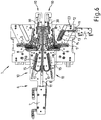
- a sealing profile receiving device 1 according to the invention is shown schematically.
- two profiles 2, 3 are connected to one another by means of a connection 4, for example for a vehicle door seal.
- a plastic injection molding unit is provided for this, which introduces the connection 4 in the injection molding process.
- the pliable, elastic profiles 2, 3 are each positioned and, if necessary, by means of holders or clamping jaws 5 adjustable along an adjustment path (arrows or double arrows) as well as non-adjustable counter holders or clamping jaws 8 and, if necessary, additionally with a support 9 or the like held.
- the clamping jaws 5, 8 are designed in such a way that they have a very large clearance or large width for the insertion / introduction of the profiles 2, 3 and are very close to the profile 2, 3 for the casting process, so that the liquid or flowable plastic for the connection 4 is correctly shaped during the injection process.
- the sealing profile receiving device 1 is not only “tailored” or designed individually for the vehicle, but is usually also designed in such a way that these are at the same time can accommodate the profiles 2, 3 for both vehicle seals. For the sake of clarity, in Figure 1 only one half of a sealing profile receiving device 1 is shown.
- drive units 6 according to the invention which preferably each include a pneumatic or hydraulic reciprocating piston cylinder 7 with a linearly adjustable piston rod 11 as a drive.
- the drive unit 6 according to the invention has a chain 13 comprising a plurality of chain links 16, which is guided / arranged in an advantageous guide 14 or a guide element with a groove 22.
- This chain 13 is on the one hand connected at the end to the piston rod 11 in an advantageous manner with a linearly adjustable, guided drive rod 12.
- the chain 13 is connected at the end to a slide 15 or a so-called output element.
- the slide 15 can be adjusted by means of the chain 13 guided in the guide 14 with both a compressive force and a tensile force according to the double arrows shown.
- a stroke-piston-cylinder 7 that can only be loaded on one side, whereby, for example, the force of gravity or a spring force generates the return or the tensile force.
- a second variant can also be implemented without great structural effort, wherein the slide 15 and the clamping jaw 5 or the ejector 10 is not arranged or protruding at the top of the guide 14, but is arranged at the bottom, with the groove 22 and the Drive, ie the components 7, 11, 12, remain unchanged.
- This very small structural change in the drive unit 6, however, leads to a reversal of the adjustment or to an output direction of the slide 15 that is rotated by 180 ° and thus the adjustment of the output.
- an adjustment path of different lengths can be realized.
- many (essential) components can be adopted completely or almost completely unchanged for the most varied or individual variants and the drive can thus be standardized. This reduces the constructive and also the economic effort.
- the great flexibility of the drive unit 6 according to the invention is also made possible by the further variants according to FIGS Figures 5 to 8 illustrated.
- the variant according to Figure 5 a drive rod 12 to which two chains 13 are fixed at the same time and which drives them and two slides 15. These two slides 15 can, for example, drive or (vertically) lift a / a comparatively large plate or clamping jaw 5 or ejector 10. This prevents the very large, heavy (metal) plate or clamping jaw 5, ejector 10, etc. from tilting or tilting, etc.
- the symbolic dashed line 29 two different plates or clamping jaws 5 or ejectors 10 can be adjusted or raised simultaneously / synchronously.
- the chains 13 used have a deflection of more than 180 ° and the slide 15 shown can accordingly have an incline or inclined plane and also be in operative connection with a second element, not shown, having a corresponding incline, and a (vertical ) Generate lifting of the or a second, separate ejector device.
- This variant also shows, among other things, the advantageous dual use of essential components of the drive unit 6 according to the invention and also the space-saving design of four simultaneous, separate adjustment paths / components.
- Figure 6 a variant of a further drive unit 6 according to the invention can be seen, the guided chain 13 realizing a deflection by approx. 60 °.
- the drive units 6 or the stroke-piston-cylinder 7 or the piston rod 11 they can be adapted to the given (spatial) framework conditions without great effort.
- Figure 7 illustrates a further variant, the chain 13 being guided around an obstacle 25, for example a supply line, a shaft, a duct passage or the like.
- an obstacle 25 for example a supply line, a shaft, a duct passage or the like.
- a correspondingly designed guide 14 or groove 22 of the guide element 23 is to be provided.
- the other, essential components can in turn be used unchanged.
- Figure 8 shows a further variant, the chain 13 driving or adjusting a wheel 26 that can rotate about an axis 27.
- the linear movement of the piston rod 11 can be converted into a rotation of the wheel 26, with which, for example, a rotary movement of a clamping jaw 5, a casting mold element or the like can be generated.
- essential components of the drive unit 6 can be adopted unchanged.
- the chain 13 or the chain links 16 advantageously comprise tabs 18 which are connected to one another by means of axles 19. There are rollers 17 between the tabs provided, which have running surfaces on the circumference, which in turn run / roll on guide surfaces of the groove 22 or of the guide 14.
- the diameter of the rollers 17 are preferably greater than the height of the tabs, so that only the rollers 17 are guided by the guide 14 or groove 22.
- the rollers 17 and / or the guide 14 or groove 22 can have a (surface) hardening so that the service life is increased and / or lubrication can be minimized.
- rollers 17 are advantageously provided / arranged along the axes 19, which effectively prevents tilting / tilting. This is of great advantage both with regard to abrasion and wear and with regard to the ease of movement of the chain 13 in the guide 14, especially in the bend 28.
- the groove 22 or the guide element 23 is closed by means of a cover element 24 and / or the slide 15 or is formed into a closed, full-circumferential guide 14. It is also clear here that the groove 22 or the guide 14 has a certain amount of play, in particular laterally along the axis 19, in order to reduce friction, among other things.
- a screw 20 and an end piece 21 are advantageously provided, but can also take place, for example, through an axle.
Description
Die Erfindung betrifft eine Dichtungsprofil-Aufnahmevorrichtung mit wenigstens einer ersten Halteeinheit zum Aufnehmen und Halten eines ersten Dichtungsprofilelementes und mit einer zweiten Halteeinheit zum Aufnehmen und Halten eines zweiten Dichtungsprofilelementes sowie mit wenigstens einer Gießeinheit zum Gießen von wenigstens einem Verbindungsabschnitt zum Verbinden des ersten Dichtungsprofilelementes mit dem zweiten Dichtungsprofilelement und/oder zum Gießen von einem ersten Endabschluss des ersten Dichtungsprofilelementes und einem zweiten Endabschluss des zweiten Dichtungsprofilelementes nach dem Oberbegriff des Anspruchs 1.The invention relates to a sealing profile receiving device with at least one first holding unit for receiving and holding a first sealing profile element and with a second holding unit for receiving and holding a second sealing profile element and with at least one casting unit for casting at least one connecting section for connecting the first sealing profile element to the second Sealing profile element and / or for casting a first end termination of the first sealing profile element and a second end termination of the second sealing profile element according to the preamble of claim 1.
Es ist bereits bekannt, Dichtungsprofile, zum Beispiel für Fahrzeugtüren zu fertigen, indem einzelne Profilteile an ein erstes Profil, ein sogenanntes zentrales Profil, angespritzt werden (z.B.
Auch separate Anspritzvorgänge, mit denen kein Profil angefügt wird, sondern lediglich das Ende eines Profils mit einem Kunststoffabschluss versehen wird, können durchgeführt werden. Hierbei werden üblicherweise in der Serienfertigung mindestens zwei, jedoch auch mehrere Profile gleichzeitig bearbeitet, d.h. es werden mit einem gemeinsamen Anspritzvorgang bzw. in einer gemeinsamen Aufnahmevorrichtung an vier Profile entsprechende Enden bzw. Abschlüsse angegossen.Separate injection molding processes, with which no profile is attached, but only the end of a profile is provided with a plastic closure, can also be carried out. In this case, at least two, but also several profiles are usually processed at the same time in series production, ie corresponding ends or closures are cast onto four profiles using a common injection molding process or in a common receiving device.
Üblicherweise sind derartige Profile bzw. Profilteile vergleichsweise lang sowie dünn und bestehen im Wesentlichen aus elastischem, weichem Material mit hohem Reibkoeffizienten wie thermoplastischem Elastomer (TPE) oder Kautschuke bzw. Gummis, z.B. EPDM, TPO, TPU, PP, PPE, PIB, PS, PETP, POM, TPU oder dergleichen. Deshalb müssen diese Profile in die Aufnahmevorrichtungen bzw. Halterungen/Formen mit großem Spiel bzw. Luft eingebracht werden und zum Gießen müssen die Formen bzw. Halterungen sehr dicht anliegen bzw. eingeklemmt werden und mit großem Spiel bzw. Luft wieder ausgenommen werden. So sind die Halterungen meist zumindest zweiteilig ausgebildet, wobei mindestens eine Komponente bzw. ein Element relativ zum anderen verstellbar ist. Auch müssen die fertigen Profile vielfach aus der Form/Halterung geworfen werden, um sie zu entnehmen, so dass nachfolgend ein neues Profil mit der Aufnahmevorrichtung gefertigt werden kann.Usually such profiles or profile parts are comparatively long and thin and essentially consist of elastic, soft material with a high coefficient of friction such as thermoplastic elastomer (TPE) or rubbers or rubbers, e.g. EPDM, TPO, TPU, PP, PPE, PIB, PS, PETP, POM, TPU or the like. Therefore, these profiles must be introduced into the receiving devices or holders / molds with a large amount of play or air, and for casting, the molds or holders have to lie very tightly or be clamped and removed again with a large amount of play or air. Thus, the mountings are usually designed in at least two parts, with at least one component or one element being adjustable relative to the other. In addition, the finished profiles often have to be thrown out of the mold / holder in order to remove them, so that a new profile can then be produced with the receiving device.
Für diese Verstellbewegungen der entsprechenden Komponenten bzw. Elemente sind diverse Antriebe notwendig. Aufgrund der Komplexität der Aufnahmevorrichtungen und der zum Teil nichtlinearen bzw. kurvenbahnförmigen Verstellbewegungen sowie aufgrund der unterschiedlichen Verstellwege/Längen, Verstellrichtungen, Verstellkräfte etc. werden unterschiedlichste Antriebe eingesetzt, die üblicherweise für jede Fahrzeugtürdichtung individuell gestaltet werden. Neben automatisierten Antrieben wie Hubkolbenzylinder, Zahnstangenantrieben werden auch manuelle Antriebe eingesetzt, wie z.B. Dreh-/Schenkmechanismen oder Kurvenbahnen, die mittels Handgriffen von Bedienpersonen betätigt werden.Various drives are necessary for these adjustment movements of the corresponding components or elements. Due to the complexity of the receiving devices and the partly non-linear or curved adjustment movements as well as due to the different adjustment paths / lengths, adjustment directions, adjustment forces, etc., a wide variety of drives are used, which are usually designed individually for each vehicle door seal. In addition to automated drives such as reciprocating piston cylinders and rack and pinion drives, manual drives are also used, such as rotating / pivoting mechanisms or cam tracks that are operated by operators using handgrips.
Die Komplexität der Aufnahmevorrichtungen bedingt zudem, dass u.a. die Anordnung bzw. die Verwendung der Antriebe unter großem Platzmangel leidet. So sind oftmals Umlenkungen bzw. Richtungsänderungen zwischen sog. Antrieb und sog. Abtrieb von 90°, 135° etc. notwendig, um an das zu verstellende Element/Formteil zu gelangen. Auch müssen Sicherheitsvorschriften für den freien, sicheren Zugang bzw. für die manuelle Betätigung der Bedienperson beachtet werden.The complexity of the mounting devices also means that, among other things, the arrangement or use of the drives suffers from a lack of space. Thus, deflections or changes of direction between the so-called drive and the so-called output of 90 °, 135 ° etc. are often necessary in order to get to the element / molded part to be adjusted. Safety regulations for free, safe access and manual operation by the operator must also be observed.
Bei der Verarbeitung von thermoplastischen Kunststoffen und Elastomeren sind Arbeitstemperaturen von bis zu ca. 200°C üblich, so dass die Aufnahmevorrichtung bzw. entsprechende Komponenten zum Teil beheizt und/oder gekühlt werden müssen. Demzufolge werden hohe thermische Anforderungen gerade auch an die Antriebe bzw. verstellbaren Komponenten gestellt.When processing thermoplastics and elastomers, working temperatures of up to approx. 200 ° C. are common, so that the receiving device or corresponding components have to be partially heated and / or cooled. As a result, high thermal requirements are also placed on the drives and adjustable components.
So müssen diese Antriebe bzw. verstellbaren Komponenten nicht nur den hohen Temperaturen über unzählige Fertigungszyklen standhalten, sondern müssen zudem Platz sparend ausgebildet sein und sehr flexibel angeordnet werden können, um nicht anderen Komponenten wie den Halterungen bzw. Gussformen oder der Bedienperson bzw. dem Einbringen und dem Herausnehmen der Profile im Weg zu stehen.These drives or adjustable components not only have to withstand the high temperatures over countless production cycles, but also have to be designed to save space and be able to be arranged very flexibly so that other components such as the mounts or molds or the operator or the introduction and to stand in the way of removing the profiles.
Deshalb werden bislang nicht nur die Aufnahmevorrichtungen, sondern auch die Antriebe nahezu individuell für die jeweilige Verstellung angepasst, was ein großer konstruktiver als auch wirtschaftlicher Aufwand bedeutet.Therefore, not only the receiving devices, but also the drives have so far been adapted almost individually for the respective adjustment, which means a great structural and economic effort.
Aufgabe der Erfindung ist es demgegenüber, eine Dichtungsprofil-Aufnahmevorrichtung der eingangs genannten Art vorzuschlagen, die hohe Anforderungen erfüllt und zudem wirtschaftlich günstig realisierbar ist.In contrast, it is the object of the invention to propose a sealing profile receiving device of the type mentioned at the beginning, which meets high requirements and can also be implemented in an economically favorable manner.
Diese Aufgabe wird, ausgehend von einer Dichtungsprofil-Aufnahmevorrichtung der einleitend genannten Art, durch die Merkmale des Anspruchs 1 gelöst. Durch die in den Unteransprüchen genannten Maßnahmen sind vorteilhafte Ausführungen und Weiterbildungen der Erfindung möglich.Based on a sealing profile receiving device of the type mentioned in the introduction, this object is achieved by the features of claim 1. Advantageous embodiments and developments of the invention are possible through the measures mentioned in the subclaims.
Dementsprechend zeichnet sich eine erfindungsgemäße Dichtungsprofil-Aufnahmevorrichtung dadurch aus, dass die erste und/oder zweite und/oder dritte Antriebseinheit wenigstens eine mehrere Kettenglieder umfassende Kette aufweist, wobei die Kette und/oder Kettenglieder wenigstens zwischen zwei Führungsflächen einer Führungseinheit zum Führen der Kette und/oder Kettenglieder angeordnet ist, so dass mit dem Kettenantrieb sowohl in Zugrichtung als auch in Druckrichtung der Kette eine Verstellkraft realisierbar ist.Accordingly, a sealing profile receiving device according to the invention is characterized in that the first and / or second and / or third drive unit has at least one chain comprising several chain links, the chain and / or chain links at least between two guide surfaces of a guide unit for guiding the chain and / or chain links is arranged so that an adjusting force can be implemented with the chain drive both in the pulling direction and in the pushing direction of the chain.
Mit Hilfe dieser Maßnahme wird erreicht, dass der bzw. die Antriebe sehr flexibel an unterschiedlichste Anforderungen und Platzangebote angepasst werden kann, da die Führung bzw. die Führungsflächen, an denen die verstellbaren Ketten/Kettenglieder entlang geführt werden, ohne großen Aufwand in unterschiedlichsten Gestaltungen/Formen ausgebildet/hergestellt werden können. Mit der erfindungsgemäßen geführten Kette können sowohl Zugkräfte als auch Druckkräfte auf das zu verstellende Elemente erzeugt werden, so dass diese vorteilhaft in zwei entgegengesetzte Richtungen mit Kraft beaufschlagt werden können. Dies ermöglicht ein vorteilhaftes Öffnen und Schließen der Halteeinheiten und/oder Auswerfer etc. in besonders kompakter Bauweise.With the help of this measure it is achieved that the drive (s) can be adapted very flexibly to the most varied of requirements and available space, since the guide or the guide surfaces, along which the adjustable chains / chain links are guided, can be made in a wide variety of designs without great effort. Forms can be formed / manufactured. With the guided chain according to the invention, both tensile forces and compressive forces can be generated on the element to be adjusted, so that force can advantageously be applied to them in two opposite directions. This enables an advantageous opening and closing of the Holding units and / or ejectors etc. in a particularly compact design.
Gemäß der Erfindung können die kompakt ausgebildeten Antriebe bzw. Antriebseinheiten für die individuellen Dichtungsprofil-Aufnahmevorrichtungen standardisiert werden, obwohl die Antriebe an die unterschiedlichsten Rahmenbedingungen angepasst werden müssen, wie Platzangebot, wenige Positionierungsmöglichkeiten versus Freihalteräume für die Bedienperson etc., Ausrichtung zum zu verstellenden Element, Länge der Verstellwege, unterschiedliche Verstellwege bzw. -abschnitte wie z.B. Dreh- und/oder Schwenkbewegung und/oder Kurvenbahn und/oder Linearbewegung. Für all diese unterschiedlichen Rahmenbedingungen, insb. unterschiedliche Verstellwege, mussten bislang unterschiedliche Antriebe entwickelt werden. Dies führte zu hohen Entwicklungs- und Herstellungskosten entsprechend individueller Dichtungsprofil-Aufnahmevorrichtungen. Eine Standardisierung des Antriebs bzw. der wesentlichen Komponenten der Antriebseinheiten gemäß der Erfindung für Dichtungsprofil-Aufnahmevorrichtungen wirkt sich wirtschaftlich besonders positiv aus.According to the invention, the compact drives or drive units for the individual sealing profile receiving devices can be standardized, although the drives have to be adapted to the most varied of framework conditions, such as space, few positioning options versus free space for the operator, etc., alignment with the element to be adjusted, Length of the adjustment paths, different adjustment paths or sections such as, for example, rotary and / or pivoting movement and / or cam track and / or linear movement. For all these different framework conditions, especially different adjustment paths, different drives had to be developed up to now. This led to high development and manufacturing costs corresponding to individual sealing profile receiving devices. A standardization of the drive or the essential components of the drive units according to the invention for sealing profile receiving devices has a particularly positive economic effect.
Vorzugsweise wird eine Linearbewegung des verstellbaren Halteelementes und/oder des Auswerfers realisiert. Es können jedoch z.B. auch Dreh- und/oder Schwenkbewegungen, Kurvenbahnverstellungen des verstellbaren Halteelementes und/oder des Auswerfers in vorteilhafter Weise verwirklicht werden.A linear movement of the adjustable holding element and / or the ejector is preferably implemented. However, e.g. rotary and / or swivel movements, cam track adjustments of the adjustable holding element and / or the ejector can also be implemented in an advantageous manner.
Darüber hinaus kann auch aufgrund der hohen Flexibilität des Antriebs bzw. der Antriebseinheiten gemäß der Erfindung auch ein im Vergleich zum bisherigen Stand der Technik zunehmende Automatisierung der Dichtungsprofil-Aufnahmevorrichtungen verwirklicht werden. Beispielsweise können erfindungsgemäße Antriebe bzw. Antriebseinheiten auch anstelle von bislang üblichen manuellen Antrieben bzw. Handgriffen eingesetzt werden. Hierdurch kann eine körperliche Entlastung der Bedienperson erreicht werden, was die derzeit immer noch notwendige gewisse manuelle Bedienung bzw. die Person über einen gesamten Arbeitstag betrachtet mit teilweise hunderten von zu fertigenden Dichtungsprofilen produktiver macht. Zudem wird meistens eine schnellere und kontrolliertere sowie fehlerärmere Fertigung erreicht, zumindest für die Verstellungen bzw. Arbeitsschritte, bei denen keine Zwischenschritte und/oder komplexe Kurvenbahnen zu realisieren sind. Eine zunehmende Automatisierung gewährleistet auch eine deutliche Reduktion der Verletzungsgefahr für die Bedienperson, d.h. weniger manuelle Handgriffe bzw. -eingriffe verringert das Risiko, dass die Person Finger bzw. Hände einklemmt bzw. einquetscht und sich erhebliche Verletzungen zuziehen könnte.In addition, due to the high flexibility of the drive or the drive units according to the invention, an increasing automation of the sealing profile receiving devices compared to the prior art can also be achieved. For example, according to the invention Drives or drive units can also be used instead of the previously customary manual drives or handles. This makes it possible to reduce the physical strain on the operator, which makes the certain manual operation that is currently still necessary or the person over an entire working day with sometimes hundreds of sealing profiles to be produced more productive. In addition, a faster, more controlled and less error-free production is usually achieved, at least for the adjustments or work steps in which no intermediate steps and / or complex cam paths need to be implemented. Increasing automation also ensures a significant reduction in the risk of injury to the operator, ie fewer manual manipulations or interventions reduces the risk that the person's fingers or hands could be pinched or squeezed and serious injuries could be sustained.
Vorteilhafterweise umfasst die erste und/oder zweite und/oder dritte Antriebseinheit wenigstens einen Linearantrieb zum linearen Verstellen eines ersten Antriebselementes. Beispielsweise kann der Linearantrieb als Linearmotor oder das erste Antriebselement des Linearantriebes als Zahnstange oder Gewindestange ausgebildet werden. Vorzugsweise ist der Linearantrieb als Hub-Kolben-Zylindereinheit ausgebildet, wobei das erste Antriebselement als verstellbarer Kolben ausgebildet ist.The first and / or second and / or third drive unit advantageously comprises at least one linear drive for linear adjustment of a first drive element. For example, the linear drive can be designed as a linear motor or the first drive element of the linear drive can be designed as a rack or threaded rod. The linear drive is preferably designed as a stroke-piston-cylinder unit, the first drive element being designed as an adjustable piston.
In einer besonderen Weiterbildung der Erfindung sind die Kette und/oder Kettenglieder zwischen dem ersten Antriebselement und einem zweiten Antriebselement angeordnet. Hierbei kann das zweite Antriebselement in vorteilhafter Weise eine Linearbewegung realisieren. Es können jedoch z.B. auch Dreh- und/oder Schwenkbewegungen, Rotationen, (bogen-/wellenförmige) Kurvenbahnverstellungen des zweiten Antriebselementes bzw. des sog. Abtreibelementes verwirklicht werden.In a particular development of the invention, the chain and / or chain links are arranged between the first drive element and a second drive element. Here, the second drive element can advantageously realize a linear movement. However, for example, rotary and / or pivoting movements, rotations, (arcuate / wave-shaped) cam path adjustments of the second drive element or the so-called drive element can also be implemented.
In einer vorteilhaften Variante der Erfindung ist das erste Antriebselement in eine erste Verstellrichtung und das zweite Antriebselement in eine zweite Verstellrichtung verstellbar, wobei die erste Verstellrichtung winklig, insbesondere senkrecht, zur zweiten Verstellrichtung ausgerichtet ist. Hiermit kann eine vorteilhafte Umlenkung bzw. Richtungsänderung zwischen erstem Antriebselement und zweitem Antriebselement verwirklicht werden. So kann zum Beispiel eine nahezu beliebige Umlenkung von z.B. ca. 30°, 45°, 90°, 110°, 135° oder 160° etc. realisiert werden. Das bedeutet, dass eine nahezu freie bzw. beliebige Winkelwahl verwirklicht werden kann, so dass eine vorteilhafte Anpassung bzw. Flexibilität an die beengten und/oder vorgegebenen geometrischen Verhältnisse der Aufnahmevorrichtung erreicht werden kann.In an advantageous variant of the invention, the first drive element can be adjusted in a first adjustment direction and the second drive element can be adjusted in a second adjustment direction, the first adjustment direction being angled, in particular perpendicular, to the second adjustment direction. In this way, an advantageous deflection or change of direction between the first drive element and the second drive element can be achieved. For example, almost any deflection of e.g. approx. 30 °, 45 °, 90 °, 110 °, 135 ° or 160 ° etc. can be implemented. This means that an almost free or arbitrary choice of angle can be achieved, so that an advantageous adaptation or flexibility to the narrow and / or predetermined geometrical relationships of the receiving device can be achieved.
Eine entsprechende Winkelanpassung kann lediglich dadurch erreicht werden, dass die Führungseinheit entsprechend ausgebildet wird, d.h. entsprechend den von anderen Komponenten vorgegebenen Raum-/Platzverhältnissen. Kette/Kettenglieder, erstes und zweites Antriebselement sowie Antriebsvorrichtung wie Hub-Kolben-Zylindereinheit oder dergleichen brauchen gemäß der Erfindung nicht oder nur minimal angepasst/verändert werden, z.B. unterschiedlich lange Ketten durch unterschiedliche Anzahl der (standardisierten) Kettenglieder. Demzufolge kann der Hersteller von Dichtungsprofil-Aufnahmevorrichtungen bzgl. dieser wesentlichen Komponenten der Antriebseinheit gemäß der Erfindung vergleichsweise große Stückzahlen verwirklichen, was den Aufwand für Entwicklung und Konstruktion und somit gerade auch den wirtschaftlichen Aufwand erheblich reduziert.A corresponding angle adjustment can only be achieved by designing the guide unit accordingly, i.e. according to the space / space conditions specified by other components. Chain / chain links, first and second drive elements as well as drive devices such as stroke-piston-cylinder units or the like do not need to be adapted / changed according to the invention or only need to be adapted / changed to a minimal extent, e.g. chains of different lengths due to different numbers of (standardized) chain links. As a result, the manufacturer of sealing profile receiving devices with regard to these essential components of the drive unit according to the invention can produce comparatively large numbers of items, which considerably reduces the expenditure for development and construction and thus also the economic expenditure.
Vorzugsweise umfasst die Führungseinheit wenigstens eine Führungsnut und/oder Führungsausnehmung. Beispielsweise umfasst ein Führungselement die Führungsnut und/oder Führungsausnehmung, wobei in vorteilhafter Weise ein Abdeckelement/-platte oder dergleichen vorgesehen ist. Hiermit kann eine vorteilhafte geschlossene Führung der Kette bzw. Kettenglieder verwirklicht werden. Dies ist positiv bzgl. der Betriebssicherheit und der exakten Führung.The guide unit preferably comprises at least one guide groove and / or guide recess. For example, a guide element comprises the guide groove and / or guide recess, advantageously a cover element / plate or the like is provided. In this way, an advantageous closed guidance of the chain or chain links can be realized. This is positive in terms of operational safety and precise guidance.
Eine Anpassung bzw. Veränderung der Ausrichtung des Antriebes bzw. der zweiten Verstellrichtung des zweiten Antriebselementes kann hierbei lediglich durch entsprechend geänderter Form der Führungsnut und/oder Führungsausnehmung umgesetzt werden, wobei insbesondere ein Gehäuse und/oder eine äußere Form und/oder weitere Elemente der Führungseinheit nahezu unverändert bleiben können. Beispielsweise kann die Führungsnut und/oder Führungsausnehmung vorteilhafterweise mittels Span abhebender Fertigungsverfahren wie Fräsen oder dergleichen generiert werden. Dies ist kostengünstig und z.B. mit modernen CNC-Werkzeugmaschinen ohne großen Aufwand und in beliebiger Form umsetzbar.An adaptation or change in the alignment of the drive or the second adjustment direction of the second drive element can only be implemented by changing the shape of the guide groove and / or guide recess accordingly, in particular a housing and / or an outer shape and / or further elements of the guide unit can remain almost unchanged. For example, the guide groove and / or guide recess can advantageously be generated by means of machining manufacturing processes such as milling or the like. This is inexpensive and can be implemented in any form, e.g. with modern CNC machine tools, without great effort.
Vorteilhafterweise umfasst die Führungseinheit wenigstens einen gebogenen und/oder runden Führungsabschnitt zum Umlenken der Kette und/oder Kettenglieder. Hiermit ist die Umlenkung bzw. Richtungsänderung zwischen erstem Antriebselement und zweitem Antriebselement in vorteilhafter Weise umsetzbar.The guide unit advantageously comprises at least one curved and / or round guide section for deflecting the chain and / or chain links. In this way, the deflection or change of direction between the first drive element and the second drive element can be implemented in an advantageous manner.
Alternativ oder in Kombination hierzu kann die Führungseinheit wenigstens ein um eine Drehachse drehbares Umlenkrad zum Umlenken der Kette und/oder Kettenglieder umfassen. Hiermit kann eine vorteilhafte Führung der Kette bzw. Kettenglieder in der Führungseinheit verwirklicht werden. Auch kann eine vorteilhafte Drehbewegung bzw. Rotation des zweiten Antriebselementes verwirklicht werden. Das bedeutet, dass z.B. ein Linearantrieb bzw. eine Linearverstellung des ersten Antriebselementes mittels der Kette bzw. Kettenglieder gemäß der Erfindung in eine Rotation des zweiten Antriebselementes in vorteilhafter Weise transformierbar ist.Alternatively or in combination with this, the guide unit can comprise at least one deflection wheel rotatable about an axis of rotation for deflecting the chain and / or chain links. This allows the chain or chain links to be advantageously guided in the guide unit. An advantageous rotary movement or rotation of the second drive element can also be achieved. This means that, for example, a linear drive or a linear adjustment of the first drive element by means of the chain or chain links according to the invention in a Rotation of the second drive element can be transformed in an advantageous manner.
Vorteilhafterweise sind am ersten Antriebselement des Linearantriebs wenigstens zwei Ketten fixiert, so dass beim Verstellen des ersten Antriebselements zugleich die wenigstens zwei Ketten verstellt werden. Hiermit wird erreicht, dass ein einziger bzw. gemeinsamer Antrieb für z.B. zwei oder vier verschiedene, verstellbare Elemente wie Halteelemente, Auswerfer oder dergleichen verwendbar ist. Diese Doppelnutzung eines Antriebs wie eines pneumatischen oder hydraulischen Hub-Kolben-Zylinder-Antriebs reduziert den konstruktiven Aufwand und zudem den Platzbedarf. Dies ist gerade bei den komplexen Dichtungsprofil-Aufnahmevorrichtungen von entscheidendem Vorteil.Advantageously, at least two chains are fixed to the first drive element of the linear drive, so that when the first drive element is adjusted, the at least two chains are adjusted at the same time. This means that a single or common drive can be used for e.g. two or four different adjustable elements such as holding elements, ejectors or the like. This dual use of a drive such as a pneumatic or hydraulic stroke-piston-cylinder drive reduces the structural effort and also the space requirement. This is a decisive advantage especially with the complex sealing profile receiving devices.
Vorzugsweise weisen die Kette und/oder Kettenglieder wenigstens Laufflächen umfassende Laufrollen auf, wobei die Laufflächen der Laufrollen an den Führungsflächen der Führungseinheit angeordnet sind. Dies verbessert die Laufeigenschaften der Kette in der Führungseinheit und reduziert den Abrieb bzw. den Verschleiß.The chain and / or chain links preferably have running rollers comprising at least running surfaces, the running surfaces of the running rollers being arranged on the guide surfaces of the guide unit. This improves the running properties of the chain in the guide unit and reduces abrasion or wear.
In einer vorteilhaften Variante der Erfindung sind die Laufflächen der Laufrollen und/oder die Führungsflächen der Führungseinheit gehärtet. Dies verbessert nochmals die Lebensdauer und Wartungsfreundlichkeit der Führung, da eine Schmierung mit (herkömmlichen) Ölen bzw. Fetten durch die zum Teil hohen Temperaturen von ca. 200°C sehr eingeschränkt ist.In an advantageous variant of the invention, the running surfaces of the rollers and / or the guide surfaces of the guide unit are hardened. This further improves the service life and ease of maintenance of the guide, since lubrication with (conventional) oils or greases is very limited due to the sometimes high temperatures of approx. 200 ° C.
Aufgrund der zum Teil sehr heißen Arbeitstemperaturen sind Teile der Antriebseinheiten bzw. die Antriebskomponenten wie z.B. die Hub-Kolben-Zylinderantriebe oder dergleichen gegenüber den ca. 200°C heißen Gussformen bzw. Komponenten der Aufnahmevorrichtung gemäß der Erfindung thermisch isoliert und/oder abgeschirmt. Beispielsweise sind in vorteilhafter Weise thermische Isolierelemente/-schichten zwischen Halteinheit und Antriebseinheit und/oder von Teilen der Antriebseinheit vorgesehen. Dagegen kann die Führungsvorrichtung und/oder die Kette und/oder Kettenglieder gemäß der Erfindung durchaus im heißeren Bereich der Aufnahmevorrichtung angeordnet werden.Due to the sometimes very hot working temperatures, parts of the drive units or the drive components, such as the stroke-piston-cylinder drives or the like, are thermally insulated from the molds or components of the receiving device according to the invention, which are about 200 ° C and / or shielded. For example, thermal insulation elements / layers are advantageously provided between the holding unit and the drive unit and / or parts of the drive unit. In contrast, the guide device and / or the chain and / or chain links according to the invention can definitely be arranged in the hotter area of the receiving device.
Gerade Metallketten können durchaus auch Temperaturen von ca. 200°C vertragen, insbesondere mit den vorteilhaften Laufrollen kann eine relativ lange Lebensdauer erreicht werden, selbst ohne herkömmliche oder mit minimaler bzw. spezieller Schmierung.Metal chains in particular can also withstand temperatures of approx. 200 ° C. A relatively long service life can be achieved with the advantageous rollers, even without conventional or with minimal or special lubrication.
Die Kette und/oder Führungseinheit gemäß der Erfindung kann als vorteilhafte Abstandseinheit und/oder thermische Isolationsvorrichtung zwischen zu verstellendem Element/Auswerfer bzw. dem heißen Arbeitsbereich und der Antriebskomponente wie Hubkolben etc. bzw. einem nicht-heißen bzw. relativ kalten, insb. gekühlten Bereich der Aufnahmevorrichtung gemäß der Erfindung ausgebildet/eingesetzt werden.The chain and / or guide unit according to the invention can be used as an advantageous spacer unit and / or thermal insulation device between the element to be adjusted / ejector or the hot working area and the drive component such as reciprocating piston etc. or a non-hot or relatively cold, especially cooled Area of the receiving device according to the invention can be formed / used.
Eine Breite und/oder Höhe der Führung bzw. der Führungsnut und/oder Führungsausnehmung hat eine vergleichbare Größe wie eine Breite und/oder Höhe der Kette und/oder Kettenglieder und/oder Laufrollen. Hiermit wird die Führung weiter verbessert bzw. stabilisiert.A width and / or height of the guide or the guide groove and / or guide recess is comparable in size to a width and / or height of the chain and / or chain links and / or rollers. This further improves or stabilizes the guidance.
Vorzugsweise sind zwei Laufrollen quer zur Laufrichtung der Kette vorgesehen. Dies gewährleistet eine besonders stabile bzw. kontrollierte Führung der Kette in der Führungseinheit bzw. der Führungsnut und/oder Führungsausnehmung. Vorteilhafterweise ist wenigstens eine Lasche, insb. zwei Laschen eines Kettengliedes zwischen zwei Laufrollen der Kette angeordnet. Diese Maßnahmen unterbinden ein seitliches Kippen der Kette/Kettenglieder oder dergleichen wirkungsvoll.Preferably, two rollers are provided transversely to the direction of travel of the chain. This ensures particularly stable or controlled guidance of the chain in the guide unit or the guide groove and / or guide recess. Advantageously, there is at least one plate, especially two plates, of a chain link arranged between two rollers of the chain. These measures effectively prevent the chain / chain links or the like from tilting to the side.
Vorteilhafterweise dient die erfindungsgemäße Aufnahmevorrichtung vor allem zur Aufnahme eines ersten bzw. zentralen Dichtungsprofils insbesondere für Fahrzeugtüren oder dergleichen, wobei an das erste Profil in vorteilhafter Weise wenigstens ein weiteres Profil anzuspritzen ist. Die Aufnahmevorrichtung wird dazu in einer entsprechenden Spritzmaschine eingebaut bzw. angeordnet. Hierzu umfasst die erfindungsgemäße Aufnahmevorrichtung wenigstens eine Gussform mit vorzugsweise wenigstens zwei Formteilen bzw. Formelementen, um das erste Profil in der Form bzw. in den zwei Formteilen bzw. Formelementen zumindest abschnittsweise wenigstens während einer Gießphase und/oder einer Aushärtungs- bzw. Auskühlphase zu halten/fixieren und/oder einzuklemmen.The receiving device according to the invention is advantageously used primarily to receive a first or central sealing profile, in particular for vehicle doors or the like, with at least one further profile advantageously being injection-molded onto the first profile. For this purpose, the receiving device is installed or arranged in a corresponding injection molding machine. For this purpose, the receiving device according to the invention comprises at least one casting mold with preferably at least two mold parts or mold elements in order to hold the first profile in the mold or in the two mold parts or mold elements, at least in sections, at least during a casting phase and / or a curing or cooling phase / fix and / or clamp.
Jede der Halteeinheiten gemäß der Erfindung umfasst in vorteilhafter Weise je eine (insb. mindestens zweiteilige) Gussform, die das Profil an mehreren Seiten/Flächen, insbesondere an fünf Seiten/Flächen vollständig umschließt und in der der Anspritzvorgang durchgeführt wird. Die Form kann als Ganzes in eine Spritzmaschine eingebaut werden. Sie kann auch aus einzelnen Formteilen zusammengesetzt sein.Each of the holding units according to the invention advantageously comprises one (in particular at least two-part) casting mold that completely surrounds the profile on several sides / surfaces, in particular on five sides / surfaces, and in which the injection molding process is carried out. The mold can be installed as a whole in an injection molding machine. It can also be composed of individual molded parts.
Bei einer vorteilhaften Variante der erfindungsgemäßen Aufnahmevorrichtung sind die wenigstens zwei Halteeinheiten über eine Verbindungsvorrichtung miteinander verbunden, wobei die Verbindungsvorrichtung jeweils zwei der wenigstens zwei Formteile/-elemente miteinander verbindet. Grundsätzlich können beliebig viele Verbindungsvorrichtungen vorgesehen sein. Die Verbindungsvorrichtung dient zusätzlich zur Ausrichtung des ersten Profils, das heißt, das erste Profil kann an der Verbindungsvorrichtung anliegen und somit positioniert (zum Beispiel gerade gerichtet) werden. In vorteilhafter Weise kann das ersten Profil auf diese Weise über seine gesamte Länge oder zumindest über annähernd die gesamte Länge formstabil gehaltert werden. Die Formen wiederum besitzen eine Aufnahmeöffnung zur Aufnahme und Halterung des Profils. Zur Einbringung des Profils kann die Form auf das Profil oder umgekehrt das Profil (manuell) in die Gussform und/oder Halteeinheit eingelegt bzw. geschoben werden.In an advantageous variant of the receiving device according to the invention, the at least two holding units are connected to one another via a connecting device, the connecting device connecting two of the at least two molded parts / elements to one another. In principle, any number of connection devices can be provided. The connecting device is also used to align the first profile, that is, the first profile can bear against the connecting device and thus be positioned (for example straightened). In this way, the first profile can advantageously be held in a dimensionally stable manner over its entire length or at least over approximately its entire length. The molds in turn have a receiving opening for receiving and holding the profile. To introduce the profile, the mold can be inserted or pushed onto the profile or, conversely, the profile (manually) into the casting mold and / or holding unit.
Die erfindungsgemäße Aufnahmevorrichtung ist entsprechend dazu ausgebildet, das/die Dichtungsprofile in wenigstens einer der Gussformen wenigstens teilweise versenkbar aufzunehmen.The receiving device according to the invention is designed accordingly to receive the sealing profile (s) in at least one of the casting molds so that it can be at least partially sunk.
In der Gussform kann zum Beispiel ein weiteres Profil angespritzt werden. Auch eine weitere Gussform kann gegebenenfalls zusätzlich verwendet werden. So ist es in vorteilhafter Weise möglich, wenigstens zwei, insb. mehrere Anspritzvorgänge parallel, d.h. zeitgleich, durchzuführen. Dies gilt insbesondere für Anspritzvorgänge, bei denen nicht nur eine Endbearbeitung erfolgt bzw. ein Abschlussende angespritzt wird, sondern bei denen zwei Profile über einen Anspritzvorgang miteinander verbunden werden.For example, another profile can be injected into the mold. Another casting mold can also be used if necessary. It is thus advantageously possible to carry out at least two, in particular several, injection processes in parallel, i.e. at the same time. This applies in particular to injection processes in which not only a final processing takes place or a final end is injected, but in which two profiles are connected to one another via an injection process.
Bei einer Endbearbeitung wird in der Regel lediglich der Kunststoff auf das Profil aufgebracht, jedoch kein weiteres Profil mit dem zentralen Profil verbunden. So ist es bei einer Ausführungsvariante der Erfindung möglich, z.B. ein Ende eines Profils mit einem angespritzten Abschluss zu versehen, d.h. sog. Endanspritzung, ohne dabei ein weiteres Profil daran anzubringen. Ferner können sogenannte Positionierpins angespritzt werden, die als Referenzmarken zur Positionierung dienen können. Diese Variante ist daher besonders flexibel verwendbar.
Hier werden meist vier oder mehr Profile bzw. Anspritzvorgänge parallel, d.h. zeitgleich, durchgeführt.In the case of final processing, usually only the plastic is applied to the profile, but no further profile is connected to the central profile. In one embodiment of the invention, it is possible, for example, to provide one end of a profile with an injection-molded closure, ie so-called end injection, without attaching a further profile to it. Furthermore, so-called positioning pins can be injected, which can serve as reference marks for positioning. This variant can therefore be used in a particularly flexible manner.
In most cases, four or more profiles or injection processes are carried out in parallel, ie at the same time.
Es ist denkbar, die Aufnahmevorrichtung gemäß der Erfindung in einer einzigen Spritzmaschine einzuspannen und dort die Bearbeitungsvorgänge/Anspritzvorgänge durchzuführen. Je nach Art des zu bearbeitenden Profils kann es jedoch vorteilhaft sein, die Aufnahmevorrichtung für verschiedene Anspritzvorgänge in unterschiedlichen Spritzmaschinen einzuspannen. Die Spritzmaschinen können dabei in einer festen Position zueinander angeordnet werden. Je nach zu bearbeitendem Profil kann es andernfalls zu Platzproblemen führen, wenn die entsprechenden Spritzaggregate in Bezug auf das Profil positioniert werden.It is conceivable to clamp the receiving device according to the invention in a single injection molding machine and to carry out the machining operations / injection molding operations there. Depending on the type of profile to be machined, however, it can be advantageous to clamp the receiving device in different injection molding machines for different injection molding processes. The injection molding machines can be arranged in a fixed position to one another. Otherwise, depending on the profile to be processed, space problems can arise if the corresponding injection units are positioned in relation to the profile.
Darüber hinaus kann es auch vorteilhaft sein, verschiedene Spritzaggregate zu verwenden, wenn verschiedene Kunststoffe eingespritzt werden. Grundsätzlich ist es aber auch denkbar, die erfindungsgemäße Aufnahmevorrichtung in einer einzigen Spritzmaschine einzubinden und dort den bzw. die verschiedenen Anspritzvorgänge durchzuführen. In vorteilhafter Weise ermöglicht es die Erfindung, ein gleichzeitiges Anspritzen unterschiedlicher Spritzguss-Elemente/-Komponenten vorzunehmen, insbesondere auch von Spritzguss-Elemente/-Komponenten, die sich hinsichtlich ihrer Bearbeitungsparameter und ihrer Verarbeitungszeit unterscheiden.In addition, it can also be advantageous to use different injection units when different plastics are injected. In principle, however, it is also conceivable to integrate the receiving device according to the invention in a single injection molding machine and to carry out the various injection molding processes there. In an advantageous manner, the invention enables different injection-molded elements / components to be molded on at the same time, in particular also of injection-molded elements / components that differ with regard to their processing parameters and their processing time.
Unter einem Spritzguss-Element/-Komponente wird vorliegend der anzuspritzende Kunststoff, zum Beispiel ein thermoplastisches Elastomer oder EPDM etc. verstanden. Ferner ermöglicht die Erfindung, dass in einer Form gleichzeitig zwei unterschiedliche Spritzguss-Elemente/-Komponenten an das Profil angespritzt werden, in der Regel an unterschiedlichen Stellen des Profils.In the present case, an injection-molded element / component is understood to mean the plastic to be injected, for example a thermoplastic elastomer or EPDM, etc. Furthermore, the invention enables two different at the same time in one form Injection-molded elements / components are injected onto the profile, usually at different points on the profile.
Ein bevorzugtes Ausführungsbeispiel der Erfindung ist in der Zeichnung dargestellt und wird anhand der Figuren nachfolgend näher erläutert.A preferred embodiment of the invention is shown in the drawing and is explained in more detail below with reference to the figures.
Im Einzelnen zeigt:
- Figur 1
- eine schematische, teilweise geschnittene Draufsicht auf eine Hälfte einer ersten Aufnahmevorrichtung mit drei Antriebseinheiten gemäß der Erfindung,
- Figur 2
- eine der drei Antriebseinheiten gemäß
Figur 1 in einer schematischen, perspektivischen Ansicht, Figur 3- schematisch eine freigelegte Kette der Antriebseinheit gemäß
Figur 2 , - Figur 4
- ein schematischer Schnitt durch die Kette der Antriebseinheit gemäß
Figur 2 , Figur 5- eine schematische Variante einer Antriebseinheit gemäß der Erfindung mit einer gemeinsamen, ersten Antriebsstange mit zwei separaten Ketten gemäß der Erfindung,
Figur 6- eine schematische, teilweise geschnittene Draufsicht auf eine zweite Aufnahmevorrichtung mit einer weiteren Antriebseinheit gemäß der Erfindung, die eine gemeinsame, zweite Antriebsstange sowie zwei synchrone Ketten gemäß der Erfindung und zwei synchrone Schieber umfasst,
Figur 7- eine schematische Ansicht eine weiteren Antriebseinheit gemäß der Erfindung mit einem zu umgehenden Hindernis und
Figur 8- eine schematische Ansicht einer weiteren Antriebseinheit gemäß der Erfindung mit einem zu verstellenden, drehbaren Abtriebsrad.
- Figure 1
- a schematic, partially sectioned plan view of one half of a first receiving device with three drive units according to the invention,
- Figure 2
- one of the three drive units according to
Figure 1 in a schematic, perspective view, - Figure 3
- schematically an exposed chain of the drive unit according to
Figure 2 , - Figure 4
- a schematic section through the chain of the drive unit according to
Figure 2 , - Figure 5
- a schematic variant of a drive unit according to the invention with a common, first drive rod with two separate chains according to the invention,
- Figure 6
- a schematic, partially sectioned plan view of a second receiving device with a further drive unit according to the invention, which has a common, second drive rod and two synchronous chains according to of the invention and comprises two synchronous slides,
- Figure 7
- a schematic view of a further drive unit according to the invention with an obstacle to be bypassed and
- Figure 8
- a schematic view of a further drive unit according to the invention with a rotatable output gear to be adjusted.
In
Gemäß der Erfindung werden die biegeschlafen, elastischen Profile 2, 3 unter anderem jeweils mittels längs eines Verstellweges (Pfeile bzw. Doppelpfeile) verstellbaren Haltern bzw. Klemmbacken 5 sowie unverstellbaren Gegenhaltern bzw. Klemmbacken 8 sowie bei Bedarf zusätzlich mit einer Stütze 9 oder dergleichen positioniert und gehalten. Die Klemmbacken 5, 8 sind derart ausgebildet, dass diese für das Einlegen/Einbringend er Profile 2, 3 ein sehr großes Spiel bzw. große Weite aufweisen und für den Gießprozess sehr eng an das Profil 2, 3 anliegen bzw. verfahren werden, so dass der flüssige bzw. fließfähige Kunststoff für die Verbindung 4 beim Einspritzvorgang korrekt ausgeformt wird. So bilden jeweils ein Teil bzw. Randbereich der Klemmbacken 5, 8 sowie ggf. weitere zum Teil nicht näher dargestellte Guss-Formelemente eine (geschlossene) Gussform für den Gießprozess.According to the invention, the pliable,
Nach dem Aushärten bzw. Auskühlen der Verbindung 4 werden die verstellbaren Klemmbacken 5 wieder zurückgezogen, so dass wieder ein großes Spiel bzw. eine große Weite entsteht. Ohne nähere Darstellung in
Da für Fahrzeuge wie Autos, Lastkraftwagen etc. üblicherweise eine "linke" und eine "rechte" Fahrzeugdichtung benötigen, sind die Dichtungsprofil-Aufnahmevorrichtung 1 nicht nur individuell auf das Fahrzeug "zugeschnitten" bzw. ausgebildet, sondern meist auch derart ausgebildet, dass diese zugleich die Profile 2, 3 für beide Fahrzeugdichtungen aufnehmen können. So ist aus Gründen der Übersichtlichkeit in
Aus
Andererseits ist auch sehr wenig Platz bereits durch die große Komplexität bzw. Vielzahl der Komponenten der Dichtungsprofil-Aufnahmevorrichtung 1 im zentralen Bereich der zu gießenden Verbindung 4 vorhanden, wie u.a. die Antriebskomponenten der verstellbaren Klemmbacken 5 und Auswerfer 10 (vgl. insb.
Die benötigten Verstellbewegungen werden in vorteilhafter Weise mittels erfindungsgemäßer Antriebseinheiten 6 verwirklicht, die vorzugsweise als Antrieb jeweils einen pneumatischen oder hydraulischen Hub-Kolben-Zylinder 7 mit linear verstellbarer Kolbenstange 11 umfassen. Wie an einer Variante gemäß
Da in vorteilhafter Weise der Hub-Kolben-Zylinder 7 doppelseitig mit Druck beaufschlagbar ist, kann der Schieber 15 mittels der in der Führung 14 geführten Kette 13 sowohl mit einer Druckkraft als auch einer Zugkraft entsprechend den dargestellten Doppelpfeilen verstellt werden. Es ist jedoch auch eine Variante mit nur einseitig beaufschalgbarem Hub-Kolben-Zylinder 7 möglich, wobei z.B. die Schwerkraft oder eine Federkraft die Rückstellung bzw. die Zugkraft generiert.Since the stroke-piston-
Alternativ zur in
Die große Flexibilität der Antriebseinheit 6 gemäß der Erfindung wird auch durch die weiteren Varianten gemäß den
Bei der weitern in
Die in
Weiterhin ist der
In den
Vorzugsweise sind die Durchmesser der Rollen 17 größer als die Höhe der Laschen, so dass ausschließlich die Rollen 17 von der Führung 14 bzw. Nut 22 geführt werden. Die Rollen 17 und/oder die Führung 14 bzw. Nut 22 kann eine (Oberflächen-) Härtung aufweisen, so dass die Lebensdauer erhöht wird und/oder eine Schmierung minimiert werden kann.The diameter of the
Zudem sind in vorteilhafter Weise längs der Achsen 19 zwei Rollen 17 vorgesehen/angeordnet, was ein Verkippen/Verkanten wirkungsvoll verhindert. Dies ist sowohl bzgl. Abrieb und Verschleiß als auch bzgl. Leichtgängigkeit der Kette 13 in der Führung 14, insb. im Bogen 28 von großem Vorteil.In addition, two
In der Schnittdarstellung gemäß
Zur Anbindung bzw. Verbindung der Kette 13 einerseits mit der Antriebsstange 12 und anderseits mit dem Schieber 15 sind in vorteilhafter Weise eine Schraube 20 und ein Endstück 21 vorgesehen, kann aber auch z.B. durch eine Achse erfolgen.To connect or connect the
- 11
- AufnahmevorrichtungCradle
- 22
- Profilprofile
- 33
- Profilprofile
- 44th
- Verbindungconnection
- 55
- KlemmbackeJaw
- 66th
- AntriebseinheitDrive unit
- 77th
- Hub-Kolben-ZylinderPiston-cylinder
- 88th
- KlemmbackeJaw
- 99
- Stützesupport
- 1010
- AuswerferEjector
- 1111
- KolbenstangePiston rod
- 1212th
- AntriebsstangeDrive rod
- 1313th
- KetteChain
- 1414th
- Führungguide
- 1515th
- SchieberSlider
- 1616
- KettengliedChain link
- 1717th
- Rollerole
- 1818th
- LascheTab
- 1919th
- Achseaxis
- 2020th
- Schraubescrew
- 2121
- EndstückEnd piece
- 2222nd
- NutGroove
- 2323
- FührungselementGuide element
- 2424
- AbdeckelementCover element
- 2525th
- Hindernisobstacle
- 2626th
- Radwheel
- 2727
- Achseaxis
- 2828
- Bogenbow
- 2929
- StrichlinieDashed line
- 3030th
- HeberLifter
Claims (11)
- Sealing profile receiving device (1) having at least one first holding unit for receiving and holding a first sealing profile element (2) and having a second holding unit for receiving and holding a second sealing profile element (3), and having at least one casting unit for casting at least one connecting portion (4) for connecting the first sealing profile element (2) to the second sealing profile element (3) and/or for casting a first end termination of the first sealing profile element (2) and a second end termination of the second sealing profile element (3), wherein the first holding unit comprises at least one first holding element (8) and one second holding element (5) that is adjustable relative to the first holding element (8), and the second holding unit comprises at least one third holding element (8) and one fourth holding element (5) that is adjustable relative to the third holding element (8), wherein at least one at least partially adjustable ejector unit (10) for ejecting at least the first and/or second sealing profile element (2, 3) is provided, wherein at least one first drive unit (6) for adjusting the second holding element (5) and one second drive unit (6) for adjusting the fourth holding element (5), and also one third drive unit (6) for at least partially adjusting the ejector unit (10) are provided, wherein in particular a heating unit and/or cooling unit for at least partially heating and/or cooling the receiving device (1) is provided, characterized in that the first and/or second and/or third drive unit (6) has at least one chain (13) comprising a plurality of chain links (16), wherein the chain (13) and/or chain links (16) is/are arranged at least between two guide faces of a guide unit (14) for guiding the chain (13) and/or chain links (16), such that an adjusting force is able to be exerted both in the pulling direction and in the pushing direction of the chain (13) by way of the first and/or second and/or third drive unit (6).
- Device according to Claim 1, characterized in that the first and/or second and/or third drive unit (6) comprises at least one linear drive (7) for linearly adjusting a first drive element (12).
- Device according to either of the preceding claims, characterized in that the linear drive (7) is in the form of a reciprocating piston-cylinder unit (7).
- Device according to one of the preceding claims, characterized in that the chain (13) and/or chain links (16) is/are arranged between the first drive element (11, 12) and a second drive element (15).
- Device according to one of the preceding claims, characterized in that the first drive element (11, 12) is adjustable in a first adjusting direction and the second drive element (15) is adjustable in a second adjusting direction, wherein the first adjusting direction is oriented at an angle, in particular perpendicularly, to the second adjusting direction.
- Device according to one of the preceding claims, characterized in that the guide unit (14) comprises at least one guide slot (14) and/or guide recess.
- Device according to one of the preceding claims, characterized in that the guide unit (14) comprises at least one curved and/or round guide portion (28) for deflecting the chain (13) and/or chain links (16).
- Device according to one of the preceding claims, characterized in that the guide unit (14) comprises at least one deflection wheel (26), which is rotatable about an axis of rotation (27), for deflecting the chain (13) and/or chain links (16).
- Device according to one of the preceding claims, characterized in that at least two chains (13) are fixed to the first drive element (11, 12) of the linear drive (7), such that, when the first drive element (11, 12) is adjusted, the at least two chains (13) are adjusted at the same time.
- Device according to one of the preceding claims, characterized in that the chain (13) and/or chain links (16) has/have at least rollers (17) comprising running surfaces, wherein the running surfaces of the rollers (17) are arranged on the guide faces of the guide unit (14) .
- Plastic injection molding machine having a plastic injection molding unit for injection molding at least one plastic, and having a sealing profile receiving device (1) according to one of the preceding claims.
Priority Applications (4)
| Application Number | Priority Date | Filing Date | Title |
|---|---|---|---|
| EP18199720.6A EP3636407B1 (en) | 2018-10-10 | 2018-10-10 | Seal profile holder comprising a first and a second holding unit |
| PL18199720T PL3636407T3 (en) | 2018-10-10 | 2018-10-10 | Seal profile holder comprising a first and a second holding unit |
| US16/595,872 US11400659B2 (en) | 2018-10-10 | 2019-10-08 | Sealing profile receiving device having a first and a second holding unit |
| CN201910956937.9A CN111016056B (en) | 2018-10-10 | 2019-10-10 | Sealing material receiving device with first and second holding units |
Applications Claiming Priority (1)
| Application Number | Priority Date | Filing Date | Title |
|---|---|---|---|
| EP18199720.6A EP3636407B1 (en) | 2018-10-10 | 2018-10-10 | Seal profile holder comprising a first and a second holding unit |
Publications (2)
| Publication Number | Publication Date |
|---|---|
| EP3636407A1 EP3636407A1 (en) | 2020-04-15 |
| EP3636407B1 true EP3636407B1 (en) | 2021-03-31 |
Family
ID=63840610
Family Applications (1)
| Application Number | Title | Priority Date | Filing Date |
|---|---|---|---|
| EP18199720.6A Active EP3636407B1 (en) | 2018-10-10 | 2018-10-10 | Seal profile holder comprising a first and a second holding unit |
Country Status (4)
| Country | Link |
|---|---|
| US (1) | US11400659B2 (en) |
| EP (1) | EP3636407B1 (en) |
| CN (1) | CN111016056B (en) |
| PL (1) | PL3636407T3 (en) |
Families Citing this family (2)
| Publication number | Priority date | Publication date | Assignee | Title |
|---|---|---|---|---|
| CN113021791B (en) * | 2021-03-15 | 2023-07-25 | 鹰星精密工业(深圳)有限公司 | Long-stroke ejection device and method for injection mold |
| CN115071091B (en) * | 2022-04-29 | 2023-10-17 | 海天塑机集团有限公司 | Lubrication control method and system based on operation mode of injection molding machine |
Family Cites Families (15)
| Publication number | Priority date | Publication date | Assignee | Title |
|---|---|---|---|---|
| JPS6032575B2 (en) * | 1979-02-20 | 1985-07-29 | 三菱化学株式会社 | Welding equipment for large synthetic resin molded products |
| JPS62287631A (en) * | 1986-06-05 | 1987-12-14 | Mitsubishi Electric Corp | Resin sealing device for semiconductor element |
| US5566510A (en) * | 1994-10-26 | 1996-10-22 | Gencorp Inc. | Molded glass run channel corner assembly |
| US6092489A (en) * | 1998-01-20 | 2000-07-25 | Happy Dog Toys, Llc | Dog toy |
| GB9907173D0 (en) * | 1999-03-30 | 1999-05-26 | Renold Plc | A chain |
| JP4479448B2 (en) * | 2004-09-30 | 2010-06-09 | 豊田合成株式会社 | Weather strip, manufacturing method thereof and mold apparatus thereof |
| JP4455608B2 (en) * | 2007-03-20 | 2010-04-21 | 株式会社椿本チエイン | Cylindrical roller chain |
| HUE027260T2 (en) * | 2013-04-30 | 2016-08-29 | Webasto SE | Method and mould for producing a panel assembly |
| PL3056311T3 (en) | 2015-02-16 | 2018-07-31 | Stefan Pfaff Werkzeug- Und Formenbau Gmbh Co Kg | Process for producing a profile seal from a profile seal blank |
| EP3093115B1 (en) | 2015-05-13 | 2017-07-12 | Stefan Pfaff Werkzeug- und Formenbau GmbH Co KG | Holding device and injection method |
| MX2018005018A (en) * | 2015-10-26 | 2018-09-13 | Henniges Automotive Sealing Systems North America Inc | Method of manufacturing seal assembly with locator. |
| FR3048196B1 (en) | 2016-02-26 | 2018-04-06 | Faurecia Interieur Industrie | MOLD SEPARATION DEVICE COMPRISING A CHAIN OF ARTICULATED LINKS BETWEEN THEM |
| FR3048197B1 (en) | 2016-02-26 | 2018-04-06 | Faurecia Interieur Industrie | EJECTION DEVICE FOR MOLD COMPRISING SLIDING LINK CHAIN |
| CN107914360A (en) * | 2016-10-10 | 2018-04-17 | 衡阳新华华致橡塑制品有限公司 | The weather strip for automobile injection that built-in can be buckled connects angle mould |
| WO2018083068A1 (en) * | 2016-11-02 | 2018-05-11 | Otto Männer Innovation GmbH | Hot runner injection molding apparatus and associated flexible actuator to valve pin connection |
-
2018
- 2018-10-10 EP EP18199720.6A patent/EP3636407B1/en active Active
- 2018-10-10 PL PL18199720T patent/PL3636407T3/en unknown
-
2019
- 2019-10-08 US US16/595,872 patent/US11400659B2/en active Active
- 2019-10-10 CN CN201910956937.9A patent/CN111016056B/en active Active
Non-Patent Citations (1)
| Title |
|---|
| None * |
Also Published As
| Publication number | Publication date |
|---|---|
| US20200114587A1 (en) | 2020-04-16 |
| PL3636407T3 (en) | 2021-11-29 |
| EP3636407A1 (en) | 2020-04-15 |
| CN111016056B (en) | 2022-06-14 |
| US11400659B2 (en) | 2022-08-02 |
| CN111016056A (en) | 2020-04-17 |
Similar Documents
| Publication | Publication Date | Title |
|---|---|---|
| EP0895848B1 (en) | Device for producing injection moulded articles from at least two plastic melts | |
| EP3636407B1 (en) | Seal profile holder comprising a first and a second holding unit | |
| DE102014116087A1 (en) | Coupled blow molding apparatus of a rotary blow molding machine and method for operating the same | |
| DE102018202473B4 (en) | Holding device for holding composite panels, tool and method | |
| WO2013072459A2 (en) | Locking device for pillars of a plastics processing machine | |
| WO2001092168A1 (en) | Blow mold and method for adjusting a blow mold | |
| DE102007028434B3 (en) | Fully automatic hold-down for a mold | |
| EP0631857A1 (en) | Plastic injection moulding machine with a mould closing unit | |
| EP1858682A1 (en) | Arrangement for receiving a mould | |
| DE19922684C2 (en) | Blow molding machine for low-waste blowing | |
| EP1848577B1 (en) | Injection moulding machine for processing plastic materials | |
| DE20321004U1 (en) | Movable platen locking system for an injection molding machine has cheeks which grip the tiebar assisted by spring force in the locking direction | |
| EP0728540B1 (en) | Tool for shaping sheet metal | |
| DE10308303B4 (en) | Injection molding device with a locking device | |
| DE102011014783B4 (en) | Locking device for spars of a plastic processing machine | |
| DE102011015943B4 (en) | Locking device for columns of a plastic processing machine | |
| EP1613461B1 (en) | Moulding device | |
| DE19925325C2 (en) | Closing unit for a machine for processing injection-moldable material | |
| DE102013008636B3 (en) | Positioning unit for use in the bodywork of the automotive industry | |
| DE102013214244B3 (en) | Injection molding machine with a clamping unit | |
| EP3481565A1 (en) | Stretch bending machine and method for deforming a workpiece | |
| DE4216827C1 (en) | Mold closing device for injection molding machines for applying high clamping forces | |
| DE102017102383A1 (en) | Device and method for forming plastic preforms to plastic containers with decoupled drive unit | |
| EP0309613A1 (en) | Parallel guiding ways for linear drives | |
| DD250287A1 (en) | CLAMP CLAW |
Legal Events
| Date | Code | Title | Description |
|---|---|---|---|
| PUAI | Public reference made under article 153(3) epc to a published international application that has entered the european phase |
Free format text: ORIGINAL CODE: 0009012 |
|
| STAA | Information on the status of an ep patent application or granted ep patent |
Free format text: STATUS: THE APPLICATION HAS BEEN PUBLISHED |
|
| AK | Designated contracting states |
Kind code of ref document: A1 Designated state(s): AL AT BE BG CH CY CZ DE DK EE ES FI FR GB GR HR HU IE IS IT LI LT LU LV MC MK MT NL NO PL PT RO RS SE SI SK SM TR |
|
| AX | Request for extension of the european patent |
Extension state: BA ME |
|
| STAA | Information on the status of an ep patent application or granted ep patent |
Free format text: STATUS: REQUEST FOR EXAMINATION WAS MADE |
|
| 17P | Request for examination filed |
Effective date: 20200515 |
|
| RBV | Designated contracting states (corrected) |
Designated state(s): AL AT BE BG CH CY CZ DE DK EE ES FI FR GB GR HR HU IE IS IT LI LT LU LV MC MK MT NL NO PL PT RO RS SE SI SK SM TR |
|
| GRAP | Despatch of communication of intention to grant a patent |
Free format text: ORIGINAL CODE: EPIDOSNIGR1 |
|
| STAA | Information on the status of an ep patent application or granted ep patent |
Free format text: STATUS: GRANT OF PATENT IS INTENDED |
|
| INTG | Intention to grant announced |
Effective date: 20201106 |
|
| RIC1 | Information provided on ipc code assigned before grant |
Ipc: F16H 19/06 20060101ALI20201023BHEP Ipc: B29L 31/26 20060101ALN20201023BHEP Ipc: F16G 13/20 20060101ALI20201023BHEP Ipc: B29C 45/33 20060101ALI20201023BHEP Ipc: B29C 45/14 20060101AFI20201023BHEP |
|
| GRAS | Grant fee paid |
Free format text: ORIGINAL CODE: EPIDOSNIGR3 |
|
| GRAA | (expected) grant |
Free format text: ORIGINAL CODE: 0009210 |
|
| STAA | Information on the status of an ep patent application or granted ep patent |
Free format text: STATUS: THE PATENT HAS BEEN GRANTED |
|
| AK | Designated contracting states |
Kind code of ref document: B1 Designated state(s): AL AT BE BG CH CY CZ DE DK EE ES FI FR GB GR HR HU IE IS IT LI LT LU LV MC MK MT NL NO PL PT RO RS SE SI SK SM TR |
|
| REG | Reference to a national code |
Ref country code: GB Ref legal event code: FG4D Free format text: NOT ENGLISH Ref country code: CH Ref legal event code: EP |
|
| REG | Reference to a national code |
Ref country code: DE Ref legal event code: R096 Ref document number: 502018004510 Country of ref document: DE Ref country code: AT Ref legal event code: REF Ref document number: 1376444 Country of ref document: AT Kind code of ref document: T Effective date: 20210415 |
|
| REG | Reference to a national code |
Ref country code: IE Ref legal event code: FG4D Free format text: LANGUAGE OF EP DOCUMENT: GERMAN |
|
| REG | Reference to a national code |
Ref country code: LT Ref legal event code: MG9D |
|
| PG25 | Lapsed in a contracting state [announced via postgrant information from national office to epo] |
Ref country code: NO Free format text: LAPSE BECAUSE OF FAILURE TO SUBMIT A TRANSLATION OF THE DESCRIPTION OR TO PAY THE FEE WITHIN THE PRESCRIBED TIME-LIMIT Effective date: 20210630 Ref country code: BG Free format text: LAPSE BECAUSE OF FAILURE TO SUBMIT A TRANSLATION OF THE DESCRIPTION OR TO PAY THE FEE WITHIN THE PRESCRIBED TIME-LIMIT Effective date: 20210630 Ref country code: FI Free format text: LAPSE BECAUSE OF FAILURE TO SUBMIT A TRANSLATION OF THE DESCRIPTION OR TO PAY THE FEE WITHIN THE PRESCRIBED TIME-LIMIT Effective date: 20210331 Ref country code: HR Free format text: LAPSE BECAUSE OF FAILURE TO SUBMIT A TRANSLATION OF THE DESCRIPTION OR TO PAY THE FEE WITHIN THE PRESCRIBED TIME-LIMIT Effective date: 20210331 |
|
| PG25 | Lapsed in a contracting state [announced via postgrant information from national office to epo] |
Ref country code: SE Free format text: LAPSE BECAUSE OF FAILURE TO SUBMIT A TRANSLATION OF THE DESCRIPTION OR TO PAY THE FEE WITHIN THE PRESCRIBED TIME-LIMIT Effective date: 20210331 Ref country code: RS Free format text: LAPSE BECAUSE OF FAILURE TO SUBMIT A TRANSLATION OF THE DESCRIPTION OR TO PAY THE FEE WITHIN THE PRESCRIBED TIME-LIMIT Effective date: 20210331 Ref country code: LV Free format text: LAPSE BECAUSE OF FAILURE TO SUBMIT A TRANSLATION OF THE DESCRIPTION OR TO PAY THE FEE WITHIN THE PRESCRIBED TIME-LIMIT Effective date: 20210331 |
|
| REG | Reference to a national code |
Ref country code: NL Ref legal event code: MP Effective date: 20210331 |
|
| REG | Reference to a national code |
Ref country code: SK Ref legal event code: T3 Ref document number: E 37584 Country of ref document: SK |
|
| PG25 | Lapsed in a contracting state [announced via postgrant information from national office to epo] |
Ref country code: CZ Free format text: LAPSE BECAUSE OF FAILURE TO SUBMIT A TRANSLATION OF THE DESCRIPTION OR TO PAY THE FEE WITHIN THE PRESCRIBED TIME-LIMIT Effective date: 20210331 Ref country code: EE Free format text: LAPSE BECAUSE OF FAILURE TO SUBMIT A TRANSLATION OF THE DESCRIPTION OR TO PAY THE FEE WITHIN THE PRESCRIBED TIME-LIMIT Effective date: 20210331 Ref country code: LT Free format text: LAPSE BECAUSE OF FAILURE TO SUBMIT A TRANSLATION OF THE DESCRIPTION OR TO PAY THE FEE WITHIN THE PRESCRIBED TIME-LIMIT Effective date: 20210331 Ref country code: SM Free format text: LAPSE BECAUSE OF FAILURE TO SUBMIT A TRANSLATION OF THE DESCRIPTION OR TO PAY THE FEE WITHIN THE PRESCRIBED TIME-LIMIT Effective date: 20210331 Ref country code: NL Free format text: LAPSE BECAUSE OF FAILURE TO SUBMIT A TRANSLATION OF THE DESCRIPTION OR TO PAY THE FEE WITHIN THE PRESCRIBED TIME-LIMIT Effective date: 20210331 |
|
| PG25 | Lapsed in a contracting state [announced via postgrant information from national office to epo] |
Ref country code: IS Free format text: LAPSE BECAUSE OF FAILURE TO SUBMIT A TRANSLATION OF THE DESCRIPTION OR TO PAY THE FEE WITHIN THE PRESCRIBED TIME-LIMIT Effective date: 20210731 Ref country code: PT Free format text: LAPSE BECAUSE OF FAILURE TO SUBMIT A TRANSLATION OF THE DESCRIPTION OR TO PAY THE FEE WITHIN THE PRESCRIBED TIME-LIMIT Effective date: 20210802 Ref country code: RO Free format text: LAPSE BECAUSE OF FAILURE TO SUBMIT A TRANSLATION OF THE DESCRIPTION OR TO PAY THE FEE WITHIN THE PRESCRIBED TIME-LIMIT Effective date: 20210331 |
|
| REG | Reference to a national code |
Ref country code: DE Ref legal event code: R097 Ref document number: 502018004510 Country of ref document: DE |
|
| PG25 | Lapsed in a contracting state [announced via postgrant information from national office to epo] |
Ref country code: ES Free format text: LAPSE BECAUSE OF FAILURE TO SUBMIT A TRANSLATION OF THE DESCRIPTION OR TO PAY THE FEE WITHIN THE PRESCRIBED TIME-LIMIT Effective date: 20210331 Ref country code: DK Free format text: LAPSE BECAUSE OF FAILURE TO SUBMIT A TRANSLATION OF THE DESCRIPTION OR TO PAY THE FEE WITHIN THE PRESCRIBED TIME-LIMIT Effective date: 20210331 Ref country code: AL Free format text: LAPSE BECAUSE OF FAILURE TO SUBMIT A TRANSLATION OF THE DESCRIPTION OR TO PAY THE FEE WITHIN THE PRESCRIBED TIME-LIMIT Effective date: 20210331 |
|
| PLBE | No opposition filed within time limit |
Free format text: ORIGINAL CODE: 0009261 |
|
| STAA | Information on the status of an ep patent application or granted ep patent |
Free format text: STATUS: NO OPPOSITION FILED WITHIN TIME LIMIT |
|
| 26N | No opposition filed |
Effective date: 20220104 |
|
| REG | Reference to a national code |
Ref country code: CH Ref legal event code: PL |
|
| PG25 | Lapsed in a contracting state [announced via postgrant information from national office to epo] |
Ref country code: IS Free format text: LAPSE BECAUSE OF FAILURE TO SUBMIT A TRANSLATION OF THE DESCRIPTION OR TO PAY THE FEE WITHIN THE PRESCRIBED TIME-LIMIT Effective date: 20210731 |
|
| REG | Reference to a national code |
Ref country code: BE Ref legal event code: MM Effective date: 20211031 |
|
| PG25 | Lapsed in a contracting state [announced via postgrant information from national office to epo] |
Ref country code: MC Free format text: LAPSE BECAUSE OF FAILURE TO SUBMIT A TRANSLATION OF THE DESCRIPTION OR TO PAY THE FEE WITHIN THE PRESCRIBED TIME-LIMIT Effective date: 20210331 |
|
| PG25 | Lapsed in a contracting state [announced via postgrant information from national office to epo] |
Ref country code: LU Free format text: LAPSE BECAUSE OF NON-PAYMENT OF DUE FEES Effective date: 20211010 Ref country code: IT Free format text: LAPSE BECAUSE OF FAILURE TO SUBMIT A TRANSLATION OF THE DESCRIPTION OR TO PAY THE FEE WITHIN THE PRESCRIBED TIME-LIMIT Effective date: 20210331 Ref country code: BE Free format text: LAPSE BECAUSE OF NON-PAYMENT OF DUE FEES Effective date: 20211031 |
|
| PG25 | Lapsed in a contracting state [announced via postgrant information from national office to epo] |
Ref country code: LI Free format text: LAPSE BECAUSE OF NON-PAYMENT OF DUE FEES Effective date: 20211031 Ref country code: CH Free format text: LAPSE BECAUSE OF NON-PAYMENT OF DUE FEES Effective date: 20211031 |
|
| PG25 | Lapsed in a contracting state [announced via postgrant information from national office to epo] |
Ref country code: FR Free format text: LAPSE BECAUSE OF NON-PAYMENT OF DUE FEES Effective date: 20211031 |
|
| PG25 | Lapsed in a contracting state [announced via postgrant information from national office to epo] |
Ref country code: IE Free format text: LAPSE BECAUSE OF NON-PAYMENT OF DUE FEES Effective date: 20211010 |
|
| GBPC | Gb: european patent ceased through non-payment of renewal fee |
Effective date: 20221010 |
|
| PG25 | Lapsed in a contracting state [announced via postgrant information from national office to epo] |
Ref country code: CY Free format text: LAPSE BECAUSE OF FAILURE TO SUBMIT A TRANSLATION OF THE DESCRIPTION OR TO PAY THE FEE WITHIN THE PRESCRIBED TIME-LIMIT Effective date: 20210331 |
|
| PG25 | Lapsed in a contracting state [announced via postgrant information from national office to epo] |
Ref country code: HU Free format text: LAPSE BECAUSE OF FAILURE TO SUBMIT A TRANSLATION OF THE DESCRIPTION OR TO PAY THE FEE WITHIN THE PRESCRIBED TIME-LIMIT; INVALID AB INITIO Effective date: 20181010 Ref country code: GR Free format text: LAPSE BECAUSE OF FAILURE TO SUBMIT A TRANSLATION OF THE DESCRIPTION OR TO PAY THE FEE WITHIN THE PRESCRIBED TIME-LIMIT Effective date: 20210331 |
|
| PG25 | Lapsed in a contracting state [announced via postgrant information from national office to epo] |
Ref country code: GB Free format text: LAPSE BECAUSE OF NON-PAYMENT OF DUE FEES Effective date: 20221010 |
|
| PGFP | Annual fee paid to national office [announced via postgrant information from national office to epo] |
Ref country code: SK Payment date: 20231002 Year of fee payment: 6 Ref country code: PL Payment date: 20230925 Year of fee payment: 6 |
|
| PGFP | Annual fee paid to national office [announced via postgrant information from national office to epo] |
Ref country code: DE Payment date: 20231018 Year of fee payment: 6 |
|
| PG25 | Lapsed in a contracting state [announced via postgrant information from national office to epo] |
Ref country code: MK Free format text: LAPSE BECAUSE OF FAILURE TO SUBMIT A TRANSLATION OF THE DESCRIPTION OR TO PAY THE FEE WITHIN THE PRESCRIBED TIME-LIMIT Effective date: 20210331 |