EP3636363A2 - Tool module for a progressive tool system - Google Patents
Tool module for a progressive tool system Download PDFInfo
- Publication number
- EP3636363A2 EP3636363A2 EP19195830.5A EP19195830A EP3636363A2 EP 3636363 A2 EP3636363 A2 EP 3636363A2 EP 19195830 A EP19195830 A EP 19195830A EP 3636363 A2 EP3636363 A2 EP 3636363A2
- Authority
- EP
- European Patent Office
- Prior art keywords
- tool
- modules
- holding
- module
- forming
- Prior art date
- Legal status (The legal status is an assumption and is not a legal conclusion. Google has not performed a legal analysis and makes no representation as to the accuracy of the status listed.)
- Withdrawn
Links
Images
Classifications
-
- B—PERFORMING OPERATIONS; TRANSPORTING
- B21—MECHANICAL METAL-WORKING WITHOUT ESSENTIALLY REMOVING MATERIAL; PUNCHING METAL
- B21D—WORKING OR PROCESSING OF SHEET METAL OR METAL TUBES, RODS OR PROFILES WITHOUT ESSENTIALLY REMOVING MATERIAL; PUNCHING METAL
- B21D37/00—Tools as parts of machines covered by this subclass
- B21D37/08—Dies with different parts for several steps in a process
-
- B—PERFORMING OPERATIONS; TRANSPORTING
- B21—MECHANICAL METAL-WORKING WITHOUT ESSENTIALLY REMOVING MATERIAL; PUNCHING METAL
- B21D—WORKING OR PROCESSING OF SHEET METAL OR METAL TUBES, RODS OR PROFILES WITHOUT ESSENTIALLY REMOVING MATERIAL; PUNCHING METAL
- B21D37/00—Tools as parts of machines covered by this subclass
- B21D37/04—Movable or exchangeable mountings for tools
-
- B—PERFORMING OPERATIONS; TRANSPORTING
- B21—MECHANICAL METAL-WORKING WITHOUT ESSENTIALLY REMOVING MATERIAL; PUNCHING METAL
- B21D—WORKING OR PROCESSING OF SHEET METAL OR METAL TUBES, RODS OR PROFILES WITHOUT ESSENTIALLY REMOVING MATERIAL; PUNCHING METAL
- B21D37/00—Tools as parts of machines covered by this subclass
- B21D37/10—Die sets; Pillar guides
- B21D37/12—Particular guiding equipment, e.g. pliers; Special arrangements for interconnection or cooperation of dies
Definitions
- the present invention relates to a tool module for a progressive tool system, comprising a band guide area for guiding a band to be processed, an upper and a lower punch holding area for holding forming modules with a plurality of punch holding claws, each of which has an interface, an upper and a lower punch guide area for guiding the plurality of forming modules, and a plurality of forming modules, which are each held at their interface by a punch holding claw and are guided by the punch guide area.
- forming modules also referred to as “punches”, in progressive composite tool systems, which, for example, hold or bend a strip to be processed.
- the tool modules, in which these forming modules are integrated, are highly specialized in previously known systems, so that a respective construction of such a tool module or a set-up thereof requires a high degree of effort, since the individual forming modules are individually fitted and integrated into the tool module which must then be installed in the follow-on composite tool system.
- the respective interfaces of all the punch holding claws are identical to one another in the tool module according to the invention, and the shaping modules each comprise a coupling rod and an active tool part, each of the coupling rods on the one hand being a counter element for engaging with the interface of one of the punch Holding claws and on the other hand also has an interface, each of the active tool parts also having a counter element for engagement with the interface of one of the coupling rods.
- the respective interfaces of a plurality of coupling rods are also identical.
- the coupling rods are standard parts that are interchangeable between the individual forming modules and can therefore be manufactured or purchased in large numbers to save manufacturing costs.
- the interfaces of the stamp-holding claws and the interface of at least one of the coupling rods are also identical to one another.
- the interfaces of the punch holding claws and / or the interface of at least one of the coupling rods each have a cross section in the form of a segment of a circle, in particular a semicircle, and the counter elements of the coupling rods and / or the counter elements of the Tool active parts have the shape of a circular cylinder segment.
- the upper and lower stamp-holding areas can each comprise a holding plate for fixing the stamp-holding claws in terms of position and position, and a pressure plate for fixing the stamp-holding claws in terms of their height.
- the upper and the lower punch holding area can be made identical, which also applies to the upper and lower punch guide area.
- any forming modules can be used in such progressive composite tool systems and thus in the tool modules according to the invention, these can be selected in particular from a group which comprises a forming module for piloting, a forming module for bending and a forming module for holding down, the forming module for Pilot a rigid coupling rod and a pilot pin as a tool active part, the forming module for bending comprises a rigid coupling rod and, for example, a swinging tool active part, and the forming module for holding down comprises an elastic coupling rod.
- the oscillating active tool part is achieved by the connection with double hinge joints already described above, while the elastic coupling rod of the forming module can be carried out for holding down, for example, by a coil spring that runs along the extension of the coupling rod.
- At least one of the punch-holding claws can be assigned an underlay element in order to adjust its height position.
- a height compensation for the lateral offset of the punch-holding claw and active tool part can thus be created with minimal design effort while maintaining the assembled coupling rods.
- the present invention relates to a progressive tool system, comprising a machine platform which has a plurality of pairs of attachment positions for a respective tool module on a machine plate, and a plurality of tool modules, in particular comprising one or more tool modules according to the invention described above Way, which are each attached to one of the pairs of attachment positions, wherein the attachment positions on the machine plate are set up identically and the tool modules are identical in at least one outer dimension.
- the assembly of the tool modules enables a simple exchange between the tool modules and the use of standard parts as components, which results in that already described above This results in savings in terms of the costs of the components and also the time required to set up or set up the system.
- At least three pairs of mounting positions can be provided, which are equally spaced along an axis which runs through the center points of all pairs.
- the distance between the pairs of mounting positions can be between 200 and 300 mm, in particular about 250 mm.
- each of the tool modules can be on its own
- the top and bottom of each include a plunger, which is set up to engage with one of the mounting positions for mounting the tool module, and which adjusts the overall height of the tool module to the distance between the corresponding pair of mounting positions. It is thus achieved through a suitable choice of a plunger that all sub-components of the corresponding tool modules can be formed in the same way, the height and length compensation between the different pairs of attachment positions being achieved solely by the design of the respective plunger.
- the stamp guide regions and / or the stamp holding regions of at least two of the tool modules, preferably of all tool modules, can be constructed identically and thus represent normal parts.
- attachment positions and the tool modules can be set up in such a way that the tool modules can each be attached or detached as a single assembly, as a result of which the tool modules can be easily mounted at their intended attachment position and the tool modules can be prepared externally for their installation.
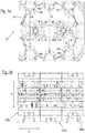
- FIGS. 1a and 1b first show in front view a progressive composite tool system according to the invention, which is generally designated by reference number 10.
- the system 10 in turn comprises a machine platform which comprises three pairs 14, 16 and 18 of attachment positions 14a and 14b, 16a and 16b and 18a and 18b on a machine plate 12 in a circular configuration.
- the progressive tool system 10 in Figure 1a shown in a disarmed state, in which no tool modules are provided at the individual mounting positions 14a to 18b, and in FIG Figure 1b in an equipped state in which the three pairs of mounting positions 14, 16 and 18 are each assigned a tool module 100a, 100b and 100c, which are each mounted with their plungers 102a to 102c at the upper and lower attachment points.
- the distances between the individual pairs of attachment points 14, 16 and 18 are in each case the same, so that the tool modules 100a to 100c can be of the same width, in particular 250 mm, in addition by comparing them by providing a thicker plunger 102b the plungers 102a and 102c compensate for the difference in vertical distance between the middle pair 16 of attachment points and the outer pairs 14 and 18 of attachment points, respectively, so that the inner height h of each of the tool modules 100a to 100c as well as that Width b of the tool modules is identical.
- This is modularization of the tool modules 100a to 100c, which was not yet provided in previously known generic progressive tool systems and apparently enables a simplified exchange for easier setup of the system 10.
- Figure 1c are now in an enlarged view the tool modules 100a to 100c from the Figure 1b shown again.
- these comprise respective upper and lower plungers 102a to 102c, the upper and lower plungers each having an identical structure in the embodiment shown here.
- the plungers 102a to 102c are also constructed in such a way that they have a counter-recess which is complementary to the design of the receiving points 14a to 18b, so that the individual tool modules 100a to 100c can be set up by sliding them from the front into the intended position of the corresponding tool module can take place.
- the fact that the tool modules 100a to 100c can be individually placed and removed in this way enables simplified setting up and dismantling of relatively small operating units, namely the individual tool modules 100a to 100c.
- the tool modules 100a to 100c are basically constructed in the same way apart from the different design of their plungers 102a to 102c, only the right tool module 100a is described below by way of example.
- the upper and lower plungers 102a are adjoined by upper and lower stamp holding regions 104a and 104b, which comprise a holding plate and a pressure plate, by means of which a plurality of stamp holding claws 106 are fixed and positioned. These holding claws 106 are described below in connection with the Figure 2 be described again in more detail.
- Forming modules 108 are in turn carried on the holding claws 106 and are further guided by a stamp guide area 110.
- stamp guide area 110 By assembling the tool modules with regard to their inner height h and their width b, both the stamp holding regions 104 and the stamp guide regions 110 of all tool modules 100a, 100b and 100c can be of the same design.
- the processing plane runs on the central axis in the horizontal direction, in which the individual forming modules 108 process, for example punch and bend, a strip to be processed, which is fed from a strip guide (not shown) according to the progressive bond principle.
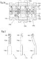
- FIG. 2 some of the forming modules are now shown as examples, which can be provided in the respective tool modules 100a to 100c and in the Figures 1a to 1c can correspond to the tool modules 108.
- a forming module 112 for holding down is shown, by means of which the material to be processed can be clamped.
- a linearly oriented bending module 114 is shown, while on the right a staggered bending module 116 is shown.
- the three forming modules 112, 114 and 116 are each constructed in such a way that they comprise a coupling rod 112a, 114a and 116a, which can be attached to an interface of a corresponding punch-holding claw 106 of one of the tool modules 100a to 100c.
- These interfaces and the corresponding counter-elements of the coupling rods 112a, 114a and 116a each form a hinge joint, so that, in particular in the case of the right bending module 116, the coupling rod 116a can be inclined.
- interfaces are again provided on the coupling rods 112a, 114a and 116a, via which the respective active tool parts 112b, 114b and 116b of the forming modules 112, 114 and 116 are then coupled to the coupling rods 112a, 114a and 116a, whereby also here, the formation of this coupling as a hinge joint allows the tool active part 116b to be aligned vertically, despite the inclined position of the coupling rod 116a.
Abstract
Die vorliegende Erfindung betrifft ein Werkzeugmodul für eine Folgeverbund-Werkzeuganlage, umfassend einen Band-Führungsbereich zum Führen eines zu bearbeitenden Bandes; einen oberen und einen unteren Stempel-Haltebereich (104) zum Halten einer Mehrzahl von Umformmodulen (108) mit einer Mehrzahl von Stempel-Haltekrallen (106), welche jeweils eine Schnittstelle aufweisen; einen oberen und einen unteren Stempel-Führungsbereich (110) zum Führen der Mehrzahl von Umformmodulen (108); und eine Mehrzahl von Umformmodulen (108), welche jeweils von einer Stempel-Haltekralle (106) an ihrer Schnittstelle gehalten und von dem Stempel-Führungsbereich (110) geführt sind. Hierbei sind die jeweiligen Schnittstellen sämtlicher Stempel-Haltekrallen (106) untereinander identisch ausgeführt; und die Umformmodule (108) umfassen jeweils eine Koppelstange und ein Werkzeugaktivteil, wobei jede der Koppelstangen einerseits ein Gegenelement zum Eingriff mit der Schnittstelle einer der Stempel-Haltekrallen (106) und andererseits ebenfalls eine Schnittstelle aufweist, wobei jedes der Werkzeugaktivteile ebenfalls ein Gegenelement zum Eingriff mit der Schnittstelle einer der Koppelstangen aufweist.The present invention relates to a tool module for a progressive tool system, comprising a belt guide area for guiding a belt to be processed; an upper and a lower stamp holding area (104) for holding a plurality of forming modules (108) with a plurality of stamp holding claws (106), each of which has an interface; upper and lower punch guide areas (110) for guiding the plurality of forming modules (108); and a plurality of forming modules (108), each of which is held at its interface by a stamp-holding claw (106) and are guided by the stamp-guiding region (110). The respective interfaces of all punch-holding claws (106) are identical to one another; and the forming modules (108) each comprise a coupling rod and a tool active part, each of the coupling rods on the one hand having a counter element for engaging with the interface of one of the punch holding claws (106) and on the other hand also having an interface, each of the tool active parts also having a counter element for engaging with the interface of one of the coupling rods.
Description
Die vorliegende Erfindung betrifft ein Werkzeugmodul für eine Folgeverbund-Werkzeuganlage, umfassend einen Band-Führungsbereich zum Führen eines zu bearbeitenden Bandes, einen oberen und einen unteren Stempel-Haltebereich zum Halten von Umformmodulen mit einer Mehrzahl von Stempel-Haltekrallen, welche jeweils eine Schnittstelle aufweisen, einen oberen und einen unteren Stempel-Führungsbereich zum Führen der Mehrzahl von Umformmodulen, und eine Mehrzahl von Umformmodulen, welche jeweils von einer Stempel-Haltekralle an ihrer Schnittstelle gehalten und von dem Stempel-Führungsbereich geführt sind.The present invention relates to a tool module for a progressive tool system, comprising a band guide area for guiding a band to be processed, an upper and a lower punch holding area for holding forming modules with a plurality of punch holding claws, each of which has an interface, an upper and a lower punch guide area for guiding the plurality of forming modules, and a plurality of forming modules, which are each held at their interface by a punch holding claw and are guided by the punch guide area.
Es ist bekannt, in Folgeverbund-Werkzeuganlagen auch als "Stempel" bezeichnete Umformmodule einzusetzen, die ein zu bearbeitendes Band beispielsweise halten oder biegen. Die Werkzeugmodule, in denen diese Umformmodule integriert sind, sind in bisher bekannten Anlagen hochgradig spezialisiert, so dass ein jeweiliger Aufbau eines derartigen Werkzugmoduls bzw. ein Rüsten davon ein hohes Maß an Aufwand erfordert, da die einzelnen Umformmodule individuell eingepasst und in das Werkzeugmodul integriert werden müssen, welches dann wiederum in der Folgeverbund-Werkzeuganlage installiert werden muss.It is known to use forming modules, also referred to as “punches”, in progressive composite tool systems, which, for example, hold or bend a strip to be processed. The tool modules, in which these forming modules are integrated, are highly specialized in previously known systems, so that a respective construction of such a tool module or a set-up thereof requires a high degree of effort, since the individual forming modules are individually fitted and integrated into the tool module which must then be installed in the follow-on composite tool system.
Es ist daher die Aufgabe der vorliegenden Erfindung, ein gattungsgemäßes Werkzeugmodul für eine Folgeverbund-Werkzeuganlage derart weiterzubilden, dass ein erhöhter Grad an Modularisierung erreicht wird und sowohl bei der Auslegung der Umformmodule als auch bei ihrer Integration in das Werkzeugmodul synergetische Effekte geschaffen werden können, die eine Konfektionierung von verwendeten Komponenten sowie einen einfachen Austausch davon ermöglichen, wodurch sowohl in der Herstellung als auch beim Rüsten derartiger Werkzeugmodule Einsparungen erzielt werden können.It is therefore the object of the present invention to further develop a generic tool module for a follow-on composite tool system in such a way that an increased degree of modularization is achieved and synergetic effects can be created both in the design of the forming modules and in their integration into the tool module enable assembly of the components used and simple replacement of them, thereby both in the manufacture and savings can be achieved when setting up such tool modules.
Um die genannte Aufgabe zu lösen, sind in dem erfindungsgemäßen Werkzeugmodul die jeweiligen Schnittstellen sämtlicher Stempel-Haltekrallen untereinander identisch ausgeführt, und die Umformmodule umfassen jeweils eine Koppelstange und ein Werkzeugaktivteil, wobei jede der Koppelstangen einerseits ein Gegenelement zum Eingriff mit der Schnittstelle einer der Stempel-Haltekrallen und andererseits ebenfalls eine Schnittstelle aufweist, wobei jedes der Werkzeugaktivteile ebenfalls ein Gegenelement zum Eingriff mit der Schnittstelle einer der Koppelstangen aufweist.In order to achieve the stated object, the respective interfaces of all the punch holding claws are identical to one another in the tool module according to the invention, and the shaping modules each comprise a coupling rod and an active tool part, each of the coupling rods on the one hand being a counter element for engaging with the interface of one of the punch Holding claws and on the other hand also has an interface, each of the active tool parts also having a counter element for engagement with the interface of one of the coupling rods.
Indem auf diese Weise eine einheitliche Schnittstelle zur Anbindung von mehreren und insbesondere verschiedenartigen Umformmodulen an den Stempel-Haltekrallen geschaffen wird, kann die oben genannte Aufgabe einer erhöhten Modularisierung gelöst werden und es können nicht nur sämtliche der Haltekrallen konfektioniert (d.h. als sogenannte "Normalien") ausgeführt sein, sondern auch beispielsweise die Koppelstangen von verschiedenartigen Umformmodulen können identisch ausgebildet sein.By creating a uniform interface for connecting several and in particular different forming modules to the punch holding claws in this way, the above-mentioned task of increased modularization can be achieved and not only all of the holding claws can be assembled (ie as so-called "normal parts") be designed, but also, for example, the coupling rods of different forming modules can be identical.
Hierbei kann beispielsweise daran gedacht werden, dass die jeweiligen Schnittstellen von einer Mehrzahl von Koppelstangen, insbesondere von sämtlichen Koppelstangen, ebenfalls identisch ausgeführt sind. Auf diese Weise stellen die Koppelstangen Normalien dar, die zwischen den einzelnen Umformmodulen austauschbar sind und daher in größeren Stückzahlen zur Einsparung von Herstellungskosten hergestellt oder angeschafft werden können.For example, it can be considered that the respective interfaces of a plurality of coupling rods, in particular of all coupling rods, are also identical. In this way, the coupling rods are standard parts that are interchangeable between the individual forming modules and can therefore be manufactured or purchased in large numbers to save manufacturing costs.
Hierbei kann beispielsweise daran gedacht werden, dass die Schnittstellen der Stempel-Haltekrallen und die Schnittstelle von wenigstens einer der Koppelstangen untereinander ebenfalls identisch ausgeführt sind.In this case, it can be considered, for example, that the interfaces of the stamp-holding claws and the interface of at least one of the coupling rods are also identical to one another.
Als eine besonders bevorzugte Ausführungsform ist denkbar, dass die Schnittstellen der Stempel-Haltekrallen und/oder die Schnittstelle von wenigstens einer der Koppelstangen jeweils einen Querschnitt in Form eines Kreissegments, insbesondere eines Halbkreises, aufweisen, und die Gegenelemente der Koppelstangen und/oder die Gegenelemente der Werkzeugaktivteile die Form eines Kreiszylinder-Segments aufweisen. Indem somit die Anbindung von wenigstens einer Koppelstange an eine entsprechende Stempel-Haltekralle und/oder von wenigstens einem der Werkzeugaktivteile an eine entsprechende Koppelstange in Form eines Scharniergelenks ausgeführt ist, ist es möglich, einen seitlichen Versatz zwischen der entsprechenden Stempel-Haltekralle und dem zugeordneten Werkzeugaktivteil zu erreichen, was insbesondere in Konfigurationen von Vorteil sein kann, in denen mehrere Werkzeugaktivteile relativ nah beieinanderliegen, wodurch ihre jeweilige Anbindung über die zugeordneten Stempel-Haltekrallen räumlich entzerrt werden kann.As a particularly preferred embodiment, it is conceivable that the interfaces of the punch holding claws and / or the interface of at least one of the coupling rods each have a cross section in the form of a segment of a circle, in particular a semicircle, and the counter elements of the coupling rods and / or the counter elements of the Tool active parts have the shape of a circular cylinder segment. By thus connecting at least one coupling rod to a corresponding stamp holding claw and / or from at least one of the active tool parts to a corresponding coupling rod in the form of a hinge joint, it is possible to offset laterally between the corresponding stamp holding claw and the associated active tool part to achieve, which can be particularly advantageous in configurations in which several active tool parts are relatively close to each other, whereby their respective connection can be spatially equalized via the assigned punch-holding claws.
Um die Stempel-Haltekrallen dementsprechend zu positionieren, können der obere und der untere Stempel-Haltebereich jeweils eine Halteplatte zur Fixierung der Stempel-Haltekrallen hinsichtlich Position und Lage sowie eine Druckplatte zur Fixierung der Stempel-Haltekrallen hinsichtlich ihrer Höhe umfassen.In order to position the stamp-holding claws accordingly, the upper and lower stamp-holding areas can each comprise a holding plate for fixing the stamp-holding claws in terms of position and position, and a pressure plate for fixing the stamp-holding claws in terms of their height.
Hierbei können der obere und der untere Stempel-Haltebereich identisch ausgeführt sein, was im Übrigen auch für den oberen und unteren Stempel-Führungsbereich gilt.Here, the upper and the lower punch holding area can be made identical, which also applies to the upper and lower punch guide area.
Wenngleich in derartigen Folgeverbund-Werkzeuganlagen und damit in den erfindungsgemäßen Werkzeugmodulen beliebige Umformmodule zum Einsatz kommen können, so können diese insbesondere aus einer Gruppe ausgewählt sein, welche ein Umformmodul zum Pilotieren, ein Umformmodul zum Biegen und ein Umformmodul zum Niederhalten umfasst, wobei das Umformmodul zum Pilotieren eine starre Koppelstange und einen Pilotstift als Werkzeugaktivteil umfasst, das Umformmodul zum Biegen eine starre Koppelstange und beispielsweise ein pendelndes Werkzeugaktivteil umfasst, und das Umformmodul zum Niederhalten eine elastische Koppelstange umfasst. Hierbei wird das pendelnde Werkzeugaktivteil durch die oben bereits beschriebene Anbindung mit doppelten Scharniergelenken erzielt, während die elastische Koppelstange des Umformmoduls zum Niederhalten beispielsweise durch eine Schraubenfeder ausgeführt werden kann, die entlang der Erstreckung der Koppelstange verläuft.Although any forming modules can be used in such progressive composite tool systems and thus in the tool modules according to the invention, these can be selected in particular from a group which comprises a forming module for piloting, a forming module for bending and a forming module for holding down, the forming module for Pilot a rigid coupling rod and a pilot pin as a tool active part, the forming module for bending comprises a rigid coupling rod and, for example, a swinging tool active part, and the forming module for holding down comprises an elastic coupling rod. Here, the oscillating active tool part is achieved by the connection with double hinge joints already described above, while the elastic coupling rod of the forming module can be carried out for holding down, for example, by a coil spring that runs along the extension of the coupling rod.
Insbesondere in Fällen, in denen ein seitlicher Versatz zwischen Werkzeugaktivteil und Stempel-Haltekralle vorgesehen ist, kann wenigstens einer der Stempel-Haltekrallen ein Unterlegelement zugeordnet sein, um ihre Höhenposition anzupassen. Somit kann mit minimalem konstruktivem Aufwand unter Beibehaltung der konfektionierten Koppelstangen ein Höhenausgleich für den seitlichen Versatz von Stempel-Haltekralle und Werkzeugaktivteil geschaffen werden.In particular, in cases where there is a lateral offset between the active tool part and the punch-holding claw, at least one of the punch-holding claws can be assigned an underlay element in order to adjust its height position. A height compensation for the lateral offset of the punch-holding claw and active tool part can thus be created with minimal design effort while maintaining the assembled coupling rods.
Gemäß einem zweiten Aspekt betrifft die vorliegende Erfindung eine Folgeverbund-Werkzeuganlage, umfassend eine Maschinenplattform, welche an einer Maschinenplatte eine Mehrzahl von Paaren von Anbaupositionen für ein jeweiliges Werkzeugmodul aufweist, und eine Mehrzahl von Werkzeugmodulen, insbesondere umfassend ein oder mehrere erfindungsgemäße Werkzeugmodule in der oben beschriebenen Weise, welche jeweils an einem der Paare von Anbaupositionen angebaut sind, wobei die Anbaupositionen an der Maschinenplatte identisch eingerichtet sind und die Werkzeugmodule in wenigstens einer Außenabmessung identisch sind.According to a second aspect, the present invention relates to a progressive tool system, comprising a machine platform which has a plurality of pairs of attachment positions for a respective tool module on a machine plate, and a plurality of tool modules, in particular comprising one or more tool modules according to the invention described above Way, which are each attached to one of the pairs of attachment positions, wherein the attachment positions on the machine plate are set up identically and the tool modules are identical in at least one outer dimension.
Während durch das Vorsehen von identischen Schnittstellen an sämtlichen Stempel-Haltekrallen eines Werkzeugmoduls bereits eine Modularisierung auf einer sehr niedrigen Ebene einer Folgeverbund-Werkzeuganlage erzielt worden ist, wird ferner durch die identische Einrichtung der Anbaupositionen einer Maschinenplattform einschließlich der ihnen zugeordneten mechanischen Antriebe sowie die identischen Außenabmessungen der Werkzeugmodule eine Modularisierung auf einer höheren Konstruktionsebene einer Folgeverbund-Werkzeuganlage geschaffen, wobei durch die Kombination der beiden Modularisierungsmöglichkeiten die Vorteile beider Aspekte der vorliegenden Erfindung ohne Weiteres verbunden werden können. Indem nämlich der zweite Aspekt der Erfindung alleine oder in Kombination mit dem ersten Aspekt der Verbindung zum Einsatz kommt, kann durch die Konfektionierung der Werkzeugmodule ein einfacher Austausch unter den Werkzeugmodulen sowie die Verwendung von Normalien als Komponenten erreicht werden, wodurch sich in der oben bereits beschriebenen Weise Einsparungen hinsichtlich der Kosten der Komponenten und auch der zum Aufbau bzw. zum Rüsten der Anlage benötigten Zeit ergeben.While the provision of identical interfaces on all punch-holding claws of a tool module has already achieved modularization at a very low level of a follow-on composite tool system, the identical arrangement of the attachment positions also makes it possible a machine platform including the mechanical drives assigned to them as well as the identical external dimensions of the tool modules, a modularization on a higher construction level of a follow-on composite tool system was created, whereby the advantages of both aspects of the present invention can be easily combined by combining the two modularization options. By using the second aspect of the invention alone or in combination with the first aspect of the connection, the assembly of the tool modules enables a simple exchange between the tool modules and the use of standard parts as components, which results in that already described above This results in savings in terms of the costs of the components and also the time required to set up or set up the system.
In einer beispielhaften Ausführungsform können wenigstens drei Paare von Anbaupositionen vorgesehen sein, welche entlang einer Achse gleich beabstandet sind, welche durch die Mittelpunkte aller Paare verläuft. Hierbei kann der genannte Abstand zwischen den Paaren von Anbaupositionen jeweils zwischen 200 und 300 mm betragen, insbesondere etwa 250 mm.In an exemplary embodiment, at least three pairs of mounting positions can be provided, which are equally spaced along an axis which runs through the center points of all pairs. Here, the distance between the pairs of mounting positions can be between 200 and 300 mm, in particular about 250 mm.
Prinzipiell ist es in diesem Zusammenhang unter anderem denkbar, die Anbaupositionen auf zwei parallelen Geraden oder einem Kreisbogen anzuordnen, so dass die jeweiligen Paare von Anbaupositionen jeweils durch eine auf jeder der parallelen Geraden angeordnete oder auf jeweils einem oberen und unteren Halbkreis des Kreisbogens angeordnete Anbauposition zusammengesetzt sind.In principle, it is conceivable in this context, among other things, to arrange the attachment positions on two parallel straight lines or an arc, so that the respective pairs of attachment positions are each composed by an attachment position arranged on each of the parallel straight lines or on an upper and lower semicircle of the circular arc are.
Um eine Modularisierung der Werkzeugmodule auch in Konfigurationen zu erreichen, in denen die Abstände der Paare der Anbaupositionen untereinander nicht gleich sind, wie im genannten Beispiel eine Anordnung derselben auf einem Kreisbogen, kann jedes der Werkzeugmodule an seiner Oberseite und seiner Unterseite jeweils einen Stößel umfassen, welcher dazu eingerichtet ist, mit einer der Anbaupositionen zum Anbauen des Werkzeugmoduls einzugreifen, und welcher die Gesamtbauhöhe des Werkzeugmoduls auf den Abstand des entsprechenden Paars von Anbaupositionen anpasst. Somit wird durch geeignete Wahl eines Stößels erreicht, dass sämtliche Unterkomponenten der entsprechenden Werkzeugmodule in gleicher Weise ausgebildet werden können, wobei der Höhen- bzw. Längenausgleich zwischen den unterschiedlichen Paaren von Anbaupositionen allein durch die Gestaltung der jeweiligen Stößel erzielt wird.In order to achieve modularization of the tool modules even in configurations in which the distances between the pairs of mounting positions are not the same, as in the example mentioned, they are arranged on a circular arc, each of the tool modules can be on its own The top and bottom of each include a plunger, which is set up to engage with one of the mounting positions for mounting the tool module, and which adjusts the overall height of the tool module to the distance between the corresponding pair of mounting positions. It is thus achieved through a suitable choice of a plunger that all sub-components of the corresponding tool modules can be formed in the same way, the height and length compensation between the different pairs of attachment positions being achieved solely by the design of the respective plunger.
In einer derartigen oder auch anderen denkbaren Konfigurationen der Anbaupositionen können die Stempel-Führungsbereiche und/oder die Stempel-Haltebereiche von wenigstens zwei der Werkzeugmodule, vorzugsweise von allen Werkzeugmodulen, gleich aufgebaut sein und somit Normalien darstellen.In such or other conceivable configurations of the attachment positions, the stamp guide regions and / or the stamp holding regions of at least two of the tool modules, preferably of all tool modules, can be constructed identically and thus represent normal parts.
Zuletzt können die Anbaupositionen und die Werkzeugmodule derart eingerichtet sein, dass die Werkzeugmodule jeweils als einheitliche Baugruppe anbaubar bzw. abbaubar sind, wodurch eine einfache Montage der Werkzeugmodule an ihrer jeweils vorgesehenen Anbauposition erreicht werden kann und die Werkzeugmodule extern für ihren Einbau vorbereitet werden können.Finally, the attachment positions and the tool modules can be set up in such a way that the tool modules can each be attached or detached as a single assembly, as a result of which the tool modules can be easily mounted at their intended attachment position and the tool modules can be prepared externally for their installation.
Weitere Merkmale und Vorteile der vorliegenden Erfindung werden aus der nachfolgenden Beschreibung von Ausführungsformen deutlich, wenn diese zusammen mit den beiliegenden Figuren betrachtet werden. Diese zeigen im Einzelnen:
- Figuren 1a bis 1c
- eine erfindungsgemäße Folgeverbund-Werkzeuganlage in abgerüstetem und gerüstetem Zustand sowie die während des Rüstens eingesetzten Werkzeugmodule in einer Einzelansicht; und
- Figur 2
- einige Beispiele von Umformmodulen, welche in den erfindungsgemäßen Werkzeugmodulen aus den
Figuren 1a bis 1c einsetzbar sind.
- Figures 1a to 1c
- a progressive composite tool system according to the invention in the disarmed and equipped state and during the tool modules used in a single view; and
- Figure 2
- some examples of forming modules, which in the tool modules according to the invention from the
Figures 1a to 1c can be used.
Die
Die Anlage 10 umfasst wiederum eine Maschinenplattform, welche an einer Maschinenplatte 12 in einer Kreiskonfiguration drei Paare 14, 16 und 18 von Anbaupositionen 14a und 14b, 16a und 16b sowie 18a und 18b umfasst. Hierbei ist die Folgeverbund-Werkzeuganlage 10 in
Hierbei zeigt sich, dass erfindungsgemäß die Abstände zwischen den einzelnen Paaren von Anbringungspunkten 14, 16 und 18 jeweils gleich sind, so dass die Werkzeugmodule 100a bis 100c von gleicher Breite sein können, insbesondere 250 mm, wobei zusätzlich durch Vorsehen eines dickeren Stößels 102b im Vergleich mit den Stößeln 102a und 102c der Unterschied in den Abständen in vertikaler Richtung zwischen dem mittleren Paar 16 von Anbringungspunkten und den jeweils äußeren Paaren 14 und 18 von Anbringungspunkten ausgeglichen wird, so dass die innere Höhe h von jedem der Werkzeugmodule 100a bis 100c ebenso wie die Breite b der Werkzeugmodule identisch ist. Auf diese Weise wird eine Modularisierung der Werkzeugmodule 100a bis 100c erzielt, die in bisher bekannten gattungsgemäßen Folgeverbund-Werkzeuganlagen noch nicht vorgesehen war und augenscheinlich einen vereinfachten Austausch für ein erleichtertes Rüsten der Anlage 10 ermöglicht.This shows that, according to the invention, the distances between the individual pairs of
In
Da die Werkzeugmodule 100a bis 100c abgesehen von der unterschiedlichen Ausbildung ihrer Stößel 102a bis 102c prinzipiell gleich aufgebaut sind, sei im Folgenden lediglich das rechte Werkzeugmodul 100a beispielhaft beschrieben. An die oberen und unteren Stößel 102a schließen sich obere und untere Stempel-Haltebereiche 104a und 104b an, welche eine Halteplatte und eine Druckplatte umfassen, mittels welcher eine Mehrzahl von Stempel-Haltekrallen 106 fixiert und positioniert sind. Diese Haltekrallen 106 werden im Folgenden im Zusammenhang mit der
An den Haltekrallen 106 sind wiederum Umformmodule 108 getragen, welche ferner von einem Stempel-Führungsbereich 110 geführt sind. Durch die Konfektionierung der Werkzeugmodule hinsichtlich ihrer inneren Höhe h und ihrer Breite b können sowohl die Stempel-Haltebereiche 104 als auch die Stempel-Führungsbereiche 110 sämtlicher Werkzeugmodule 100a, 100b und 100c gleich ausgebildet sein.Forming
Auf der Mittelachse in horizontaler Richtung verläuft schließlich die Bearbeitungsebene, in der die einzelnen Umformmodule 108 ein zu bearbeitendes Band, das von einer nicht dargestellten Bandführung dem Folgeverbund-Prinzip folgend zugeführt wird, bearbeiten, beispielsweise stanzen und biegen.Finally, the processing plane runs on the central axis in the horizontal direction, in which the
In der
Die drei Umformmodule 112, 114 und 116 sind hierbei jeweils derart aufgebaut, dass sie eine Koppelstange 112a, 114a bzw. 116a umfassen, die an einer Schnittstelle einer entsprechenden Stempel-Haltekralle 106 eines der Werkzeugmodule 100a bis 100c anbringbar ist. Diese Schnittstellen sowie die entsprechenden Gegenelemente der Koppelstangen 112a, 114a und 116a sind bilden jeweils ein Scharniergelenk, so dass insbesondere im Fall des rechten Biegemoduls 116 eine Schrägstellung der Koppelstange 116a möglich ist.The three forming
In ähnlicher Weise sind auch an den Koppelstangen 112a, 114a und 116a wieder Schnittstellen vorgesehen, über die dann die jeweiligen Werkzeugaktivteile 112b, 114b und 116b der Umformmodule 112, 114 und 116 an die Koppelstangen 112a, 114a und 116a gekoppelt sind, wobei auch hier das Ausbilden dieser Ankopplung als Scharniergelenk trotz der Schrägstellung der Koppelstange 116a eine vertikale Ausrichtung des Werkzeugaktivteils 116b ermöglicht.Similarly, interfaces are again provided on the
Claims (15)
die jeweiligen Schnittstellen sämtlicher Stempel-Haltekrallen (106) untereinander identisch ausgeführt; und
die Umformmodule (108) jeweils eine Koppelstange (112a, 114a, 116a) und ein Werkzeugaktivteil (112b, 114b, 116b) umfassen, wobei jede der Koppelstangen (112a, 114a, 116a) einerseits ein Gegenelement zum Eingriff mit der Schnittstelle einer der Stempel-Haltekrallen (106) und andererseits ebenfalls eine Schnittstelle aufweist,
wobei jedes der Werkzeugaktivteile (112b, 114b, 116b) ebenfalls ein Gegenelement zum Eingriff mit der Schnittstelle einer der Koppelstangen (112a, 114a, 116a) aufweist.Tool module for a follow-on composite tool system, comprising:
the respective interfaces of all punch-holding claws (106) are identical to one another; and
the forming modules (108) each comprise a coupling rod (112a, 114a, 116a) and a tool active part (112b, 114b, 116b), each of the coupling rods (112a, 114a, 116a) on the one hand a counter element for engaging with the interface of one of the stamping Holding claws (106) and on the other hand also has an interface,
wherein each of the active tool parts (112b, 114b, 116b) also has a counter element for engagement with the interface of one of the coupling rods (112a, 114a, 116a).
dadurch gekennzeichnet, dass die jeweiligen Schnittstellen von einer Mehrzahl von Koppelstangen (112a, 114a, 116a), insbesondere von sämtlichen Koppelstangen (112a, 114a, 116a), ebenfalls identisch ausgeführt sind.Tool module according to claim 1,
characterized in that the respective interfaces of a plurality of coupling rods (112a, 114a, 116a), in particular of all coupling rods (112a, 114a, 116a), are also identical.
dadurch gekennzeichnet, dass die Schnittstellen der Stempel-Haltekrallen (106) und die Schnittstelle von wenigstens einer der Koppelstangen (112a, 114a, 116a) ebenfalls identisch ausgeführt sind.Tool module according to claim 1 or 2,
characterized in that the interfaces of the stamp-holding claws (106) and the interface of at least one of the coupling rods (112a, 114a, 116a) are also identical.
dadurch gekennzeichnet, dass die Schnittstellen der Stempel-Haltekrallen (106) und/oder die Schnittstellen von wenigstens einer der Koppelstangen (112a, 114a, 116a) jeweils einen Querschnitt in Form eines Kreissegments, insbesondere eines Halbkreises, aufweisen, und die Gegenelemente der Koppelstangen (112a, 114a, 116a) und/oder die Gegenelemente der Werkzeugaktivteile (112b, 114b, 116b) die Form eines Kreiszylinder-Segments aufweisen.Tool module according to one of the preceding claims,
characterized in that the interfaces of the punch holding claws (106) and / or the interfaces of at least one of the coupling rods (112a, 114a, 116a) each have a cross section in the form of a segment of a circle, in particular a semicircle, and the counter elements of the coupling rods ( 112a, 114a, 116a) and / or the counter elements of the active tool parts (112b, 114b, 116b) have the shape of a circular cylinder segment.
dadurch gekennzeichnet, dass der obere und der untere Stempel-Haltebereich (104) jeweils eine Halteplatte zur Fixierung der Stempel-Haltekrallen (106) hinsichtlich Position und Lage sowie eine Druckplatte zur Fixierung der Stempel-Haltekrallen (106) hinsichtlich ihrer Höhe umfasst.Tool module according to one of the preceding claims,
characterized in that the upper and the lower stamp holding area (104) each comprise a holding plate for fixing the stamp holding claws (106) in terms of position and position, and a pressure plate for fixing the stamp holding claws (106) in terms of their height.
dadurch gekennzeichnet, dass der oberen und der untere Stempel-Führungsbereich (110) identisch ausgeführt sind.Tool module according to one of the preceding claims,
characterized in that the upper and lower punch guide areas (110) are identical.
dadurch gekennzeichnet, dass die Umformmodule (108) aus einer Gruppe ausgewählt sind, welche ein Umformmodul zum Pilotieren, ein Umformmodul zum Biegen (114, 116) und ein Umformmodul zum Niederhalten (112) umfasst,
wobei das Umformmodul zum Pilotieren eine starre Koppelstange und einen Pilotstift als Werkzeugaktivteil umfasst,
das Umformmodul zum Biegen (114, 116) eine starre Koppelstange (114a, 116a) und beispielsweise ein pendelndes Werkzeugaktivteil (116b) umfasst, und
das Umformmodul zum Niederhalten (112) eine elastische Koppelstange (112a) umfasst.Tool module according to one of the preceding claims,
characterized in that the forming modules (108) are selected from a group which comprises a forming module for piloting, a forming module for bending (114, 116) and a forming module for holding down (112),
wherein the forming module for piloting comprises a rigid coupling rod and a pilot pin as an active tool part,
the forming module for bending (114, 116) comprises a rigid coupling rod (114a, 116a) and, for example, an oscillating active tool part (116b), and
the forming module for holding down (112) comprises an elastic coupling rod (112a).
dadurch gekennzeichnet, dass wenigstens drei Paare (14, 16, 18) von Anbaupositionen vorgesehen sind, welche entlang einer Achse gleich beabstandet sind, welche durch die Mittelpunkte aller Paare (14, 16, 18) verläuft.Progressive composite tool system according to claim 9,
characterized in that at least three pairs (14, 16, 18) of mounting positions are provided which are equally spaced along an axis which runs through the center points of all pairs (14, 16, 18).
dadurch gekennzeichnet, dass der Abstand zwischen den Paaren (14, 16, 18) von Anbaupositionen jeweils zwischen 200 und 300 mm, insbesondere etwa 250 mm, beträgt.Progressive composite tool system according to claim 10,
characterized in that the distance between the pairs (14, 16, 18) of mounting positions is in each case between 200 and 300 mm, in particular approximately 250 mm.
Applications Claiming Priority (1)
| Application Number | Priority Date | Filing Date | Title |
|---|---|---|---|
| DE102018217209.9A DE102018217209A1 (en) | 2018-10-09 | 2018-10-09 | Tool module for a progressive tool system |
Publications (2)
| Publication Number | Publication Date |
|---|---|
| EP3636363A2 true EP3636363A2 (en) | 2020-04-15 |
| EP3636363A3 EP3636363A3 (en) | 2020-05-06 |
Family
ID=67875298
Family Applications (1)
| Application Number | Title | Priority Date | Filing Date |
|---|---|---|---|
| EP19195830.5A Withdrawn EP3636363A3 (en) | 2018-10-09 | 2019-09-06 | Tool module for a progressive tool system |
Country Status (2)
| Country | Link |
|---|---|
| EP (1) | EP3636363A3 (en) |
| DE (1) | DE102018217209A1 (en) |
Families Citing this family (1)
| Publication number | Priority date | Publication date | Assignee | Title |
|---|---|---|---|---|
| DE102019215750A1 (en) * | 2019-10-14 | 2021-04-15 | Otto Bihler Maschinenfabrik Gmbh & Co. Kg | Adjustable coupling for tools in stamping and forming technology |
Family Cites Families (8)
| Publication number | Priority date | Publication date | Assignee | Title |
|---|---|---|---|---|
| US1527364A (en) * | 1923-11-02 | 1925-02-24 | Kinzel John | Die mechanism for making reamers |
| DE4103302A1 (en) * | 1990-02-05 | 1991-10-17 | Heinz Finzer | Modular machining centre with drive transmission by gearing |
| DE4021346C1 (en) * | 1990-07-05 | 1991-07-04 | Alpha Maschinenbau Ag, Zuerich, Ch | |
| DE102005045727B4 (en) * | 2005-09-23 | 2009-02-05 | Benteler Automobiltechnik Gmbh | Deep drawing process and thermoforming machine |
| DE102011077308A1 (en) * | 2011-06-09 | 2012-12-13 | Otto Bihler Handels-Beteiligungs-Gmbh | Bending machine and bending tool |
| DE102013225396A1 (en) * | 2013-12-10 | 2015-06-11 | Bayerische Motoren Werke Aktiengesellschaft | Electric machine with optimized permanent magnet distribution |
| US9908171B2 (en) * | 2015-11-25 | 2018-03-06 | Btm Company Llc | Linkage press machine |
| DE102016204572A1 (en) * | 2016-03-18 | 2017-09-21 | Otto Bihler Handels-Beteiligungs-Gmbh | Forming machine and method for correcting the position of the carriage assembly of such a forming machine |
-
2018
- 2018-10-09 DE DE102018217209.9A patent/DE102018217209A1/en not_active Withdrawn
-
2019
- 2019-09-06 EP EP19195830.5A patent/EP3636363A3/en not_active Withdrawn
Also Published As
| Publication number | Publication date |
|---|---|
| DE102018217209A1 (en) | 2020-04-09 |
| EP3636363A3 (en) | 2020-05-06 |
Similar Documents
| Publication | Publication Date | Title |
|---|---|---|
| EP3271209B1 (en) | Longitudinal adjuster for a vehicle seat | |
| EP2860085A1 (en) | Subframe for a motor vehicle | |
| DE102012206288A1 (en) | Covering an inside of a side wall of a rail vehicle | |
| WO2014001373A1 (en) | Device and method for securing and orienting a guide rail | |
| DE202011108083U1 (en) | Device with at least one device for setting a guide play | |
| EP3636363A2 (en) | Tool module for a progressive tool system | |
| DE102013209111B4 (en) | Clamping device, in particular for receiving and clamping a component, and clamping system with such a clamping device | |
| DE2828477A1 (en) | CONSOLE FOR A VEHICLE SEAT | |
| EP1043116B1 (en) | Clamping device for components | |
| DE102016200905A1 (en) | High-pressure fuel pump | |
| DE202018006268U1 (en) | Tool module for a progressive tooling system | |
| DE102021129867A1 (en) | ASSEMBLY DEVICE FOR THE MANUFACTURE OF VEHICLE SEATS | |
| DE102010038814A1 (en) | Metal structure for backrest of motor vehicle seat, particularly for rear seat, has profiled baseplate and multiple, essentially even, flat framework elements, which are welded with baseplate | |
| DE102018124850A1 (en) | Conveyor strand for a conveyor | |
| AT523965B1 (en) | Bending device with deflection compensation | |
| EP3300994A1 (en) | Damping system | |
| WO2017036875A1 (en) | Bearing block | |
| EP3947236A1 (en) | Variable driver system | |
| DE102009003910A1 (en) | Mounting rail for a device for mounting wall panels on a wall and facade cladding | |
| DE102020006771A1 (en) | Housing and a blank for the production of such a housing | |
| DE102004027140A1 (en) | Mast assembly of a forklift and method of making the same | |
| EP3350054B1 (en) | Spring device for receiving lateral forces and railway vehicles comprising a spring device | |
| DE4424877B4 (en) | Device for twist-free assembly of electron beam systems | |
| EP4066688A1 (en) | Panel fastener and fastening system including the same and method | |
| EP3587716A1 (en) | Hinge part and hinge provided with at least one said hinge part |
Legal Events
| Date | Code | Title | Description |
|---|---|---|---|
| PUAI | Public reference made under article 153(3) epc to a published international application that has entered the european phase |
Free format text: ORIGINAL CODE: 0009012 |
|
| STAA | Information on the status of an ep patent application or granted ep patent |
Free format text: STATUS: THE APPLICATION HAS BEEN PUBLISHED |
|
| PUAL | Search report despatched |
Free format text: ORIGINAL CODE: 0009013 |
|
| AK | Designated contracting states |
Kind code of ref document: A2 Designated state(s): AL AT BE BG CH CY CZ DE DK EE ES FI FR GB GR HR HU IE IS IT LI LT LU LV MC MK MT NL NO PL PT RO RS SE SI SK SM TR |
|
| AX | Request for extension of the european patent |
Extension state: BA ME |
|
| AK | Designated contracting states |
Kind code of ref document: A3 Designated state(s): AL AT BE BG CH CY CZ DE DK EE ES FI FR GB GR HR HU IE IS IT LI LT LU LV MC MK MT NL NO PL PT RO RS SE SI SK SM TR |
|
| AX | Request for extension of the european patent |
Extension state: BA ME |
|
| RIC1 | Information provided on ipc code assigned before grant |
Ipc: B21D 37/08 20060101ALI20200328BHEP Ipc: B21D 37/04 20060101AFI20200328BHEP Ipc: B21D 37/12 20060101ALI20200328BHEP Ipc: B21F 1/00 20060101ALI20200328BHEP |
|
| 18D | Application deemed to be withdrawn |
Effective date: 20201107 |