EP3635947B1 - Fahrzeugbildgebungsvorrichtung - Google Patents
Fahrzeugbildgebungsvorrichtung Download PDFInfo
- Publication number
- EP3635947B1 EP3635947B1 EP18725630.0A EP18725630A EP3635947B1 EP 3635947 B1 EP3635947 B1 EP 3635947B1 EP 18725630 A EP18725630 A EP 18725630A EP 3635947 B1 EP3635947 B1 EP 3635947B1
- Authority
- EP
- European Patent Office
- Prior art keywords
- vehicle
- vehicle imaging
- camera
- cameras
- imaging station
- Prior art date
- Legal status (The legal status is an assumption and is not a legal conclusion. Google has not performed a legal analysis and makes no representation as to the accuracy of the status listed.)
- Active
Links
Images

Classifications
-
- H—ELECTRICITY
- H04—ELECTRIC COMMUNICATION TECHNIQUE
- H04N—PICTORIAL COMMUNICATION, e.g. TELEVISION
- H04N23/00—Cameras or camera modules comprising electronic image sensors; Control thereof
- H04N23/60—Control of cameras or camera modules
-
- G—PHYSICS
- G01—MEASURING; TESTING
- G01B—MEASURING LENGTH, THICKNESS OR SIMILAR LINEAR DIMENSIONS; MEASURING ANGLES; MEASURING AREAS; MEASURING IRREGULARITIES OF SURFACES OR CONTOURS
- G01B11/00—Measuring arrangements characterised by the use of optical techniques
- G01B11/30—Measuring arrangements characterised by the use of optical techniques for measuring roughness or irregularity of surfaces
-
- G—PHYSICS
- G01—MEASURING; TESTING
- G01N—INVESTIGATING OR ANALYSING MATERIALS BY DETERMINING THEIR CHEMICAL OR PHYSICAL PROPERTIES
- G01N21/00—Investigating or analysing materials by the use of optical means, i.e. using sub-millimetre waves, infrared, visible or ultraviolet light
- G01N21/84—Systems specially adapted for particular applications
- G01N21/88—Investigating the presence of flaws or contamination
- G01N21/8806—Specially adapted optical and illumination features
-
- G—PHYSICS
- G03—PHOTOGRAPHY; CINEMATOGRAPHY; ANALOGOUS TECHNIQUES USING WAVES OTHER THAN OPTICAL WAVES; ELECTROGRAPHY; HOLOGRAPHY
- G03B—APPARATUS OR ARRANGEMENTS FOR TAKING PHOTOGRAPHS OR FOR PROJECTING OR VIEWING THEM; APPARATUS OR ARRANGEMENTS EMPLOYING ANALOGOUS TECHNIQUES USING WAVES OTHER THAN OPTICAL WAVES; ACCESSORIES THEREFOR
- G03B15/00—Special procedures for taking photographs; Apparatus therefor
-
- G—PHYSICS
- G03—PHOTOGRAPHY; CINEMATOGRAPHY; ANALOGOUS TECHNIQUES USING WAVES OTHER THAN OPTICAL WAVES; ELECTROGRAPHY; HOLOGRAPHY
- G03B—APPARATUS OR ARRANGEMENTS FOR TAKING PHOTOGRAPHS OR FOR PROJECTING OR VIEWING THEM; APPARATUS OR ARRANGEMENTS EMPLOYING ANALOGOUS TECHNIQUES USING WAVES OTHER THAN OPTICAL WAVES; ACCESSORIES THEREFOR
- G03B7/00—Control of exposure by setting shutters, diaphragms or filters, separately or conjointly
-
- G—PHYSICS
- G06—COMPUTING OR CALCULATING; COUNTING
- G06T—IMAGE DATA PROCESSING OR GENERATION, IN GENERAL
- G06T7/00—Image analysis
- G06T7/0002—Inspection of images, e.g. flaw detection
-
- H—ELECTRICITY
- H04—ELECTRIC COMMUNICATION TECHNIQUE
- H04N—PICTORIAL COMMUNICATION, e.g. TELEVISION
- H04N23/00—Cameras or camera modules comprising electronic image sensors; Control thereof
- H04N23/50—Constructional details
- H04N23/54—Mounting of pick-up tubes, electronic image sensors, deviation or focusing coils
-
- H—ELECTRICITY
- H04—ELECTRIC COMMUNICATION TECHNIQUE
- H04N—PICTORIAL COMMUNICATION, e.g. TELEVISION
- H04N23/00—Cameras or camera modules comprising electronic image sensors; Control thereof
- H04N23/60—Control of cameras or camera modules
- H04N23/61—Control of cameras or camera modules based on recognised objects
-
- H—ELECTRICITY
- H04—ELECTRIC COMMUNICATION TECHNIQUE
- H04N—PICTORIAL COMMUNICATION, e.g. TELEVISION
- H04N23/00—Cameras or camera modules comprising electronic image sensors; Control thereof
- H04N23/90—Arrangement of cameras or camera modules, e.g. multiple cameras in TV studios or sports stadiums
-
- H—ELECTRICITY
- H04—ELECTRIC COMMUNICATION TECHNIQUE
- H04N—PICTORIAL COMMUNICATION, e.g. TELEVISION
- H04N5/00—Details of television systems
- H04N5/222—Studio circuitry; Studio devices; Studio equipment
-
- H—ELECTRICITY
- H04—ELECTRIC COMMUNICATION TECHNIQUE
- H04N—PICTORIAL COMMUNICATION, e.g. TELEVISION
- H04N7/00—Television systems
- H04N7/18—Closed-circuit television [CCTV] systems, i.e. systems in which the video signal is not broadcast
-
- G—PHYSICS
- G01—MEASURING; TESTING
- G01N—INVESTIGATING OR ANALYSING MATERIALS BY DETERMINING THEIR CHEMICAL OR PHYSICAL PROPERTIES
- G01N21/00—Investigating or analysing materials by the use of optical means, i.e. using sub-millimetre waves, infrared, visible or ultraviolet light
- G01N21/84—Systems specially adapted for particular applications
- G01N21/88—Investigating the presence of flaws or contamination
- G01N21/8806—Specially adapted optical and illumination features
- G01N2021/8809—Adjustment for highlighting flaws
-
- G—PHYSICS
- G06—COMPUTING OR CALCULATING; COUNTING
- G06T—IMAGE DATA PROCESSING OR GENERATION, IN GENERAL
- G06T2207/00—Indexing scheme for image analysis or image enhancement
- G06T2207/30—Subject of image; Context of image processing
- G06T2207/30248—Vehicle exterior or interior
Definitions
- This invention relates to the imaging of vehicles.
- US 2015/097924A1 describes a front-end image acquisition component acquiring photographs and/or videos of various goods, vehicles, vessels, and/or real estate fixtures.
- an imaging studio for acquiring images of a vehicle that passes between two camera towers 604 on which a plurality of cameras 608C-F are installed in order to capture images of the wheels, of the sides of the vehicle and of the rear of the vehicle.
- GB2500716 A describes a booth including a plurality of cameras positioned around the booth so that images of the entire bodywork of the vehicle can be captured when the driver stops the vehicle at a target location within the booth.
- the first height can be between 0.6 m and 1 m.
- the second height can be between 1 m and 1.5 m
- the respective heights and angles of the cameras enable a substantial part of the bodywork of a vehicle passing through the vehicle imaging volume to be captured whilst minimising the number of cameras required.
- the camera array can additionally include a fifth camera located at a third height.
- the third height can be between 1.5 m and 2 m.
- the camera array can additionally include a further support structure arranged to support an additional overhead camera.
- the camera array is also arranged to capture one or more images of a roof of a vehicle passing through the vehicle imaging volume.
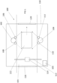
- a vehicle imaging station is shown generally at 100 in Figure 1 .
- the vehicle imaging station 100 is arranged around a roadway 101, which is a path suitable for a vehicle 122 to travel along.
- Cameras 106, 108, 110 and 112 are arranged at different points along the roadway, such that the fields of view of these cameras combine to cover or define a vehicle imaging volume.
- vehicle speed detection device 114 measures the speed of the vehicle. Control unit 103 then adjusts the shutter speed of the cameras 106, 108, 110 and 112 based on the measured speed of the vehicle. Cameras 106, 108, 110 and 112 then capture images of the vehicle 122 as it passes through the vehicle imaging volume.
- Vehicle imaging station 100 comprises a first support post 102 located on one side of a vehicle roadway and a second support post 104 located on an opposite side of the vehicle roadway.
- a first camera 106 is located towards an upper end of the first support post 102 and is angled towards the exit of the vehicle imaging station 100 such that the first camera 106 can capture images of an upper part of a first side of a vehicle and the back of a vehicle as the vehicle moves through the vehicle imaging volume.
- a second camera 108 is located towards a lower end of the first support post 102, and is angled towards the entrance of the vehicle imaging station such that the second camera 108 can capture images of the front of the vehicle and a lower part of the first side of the vehicle as the vehicle moves through the vehicle imaging volume.
- a third camera 110 is located towards a lower end of the second support post 104 and is angled towards the entrance of the vehicle imaging station such that the third camera 110 can capture images of a lower part of a second side of a vehicle and the front of a vehicle as the vehicle moves through the vehicle imaging volume.
- a fourth camera 112 is located towards an upper end of the second support post 104 and is angled towards the exit of the vehicle imaging station such that the fourth camera 112 can capture images of the back of the vehicle and an upper part of the second side of the vehicle as the vehicle moves through the vehicle imaging volume.
- each of the first, second, third and fourth cameras 106, 108, 110, 112 have a horizontal orientation (i.e. parallel to the roadway 101).
- the cameras could alternatively be angled with respect to the roadway in some embodiments.
- the first 106, second 108, third 110 and fourth 112 cameras together make up a four part camera system arranged to capture multiple images of a vehicle as it passes through the vehicle imaging volume.
- the vehicle imaging station may additionally include a support structure 113 arranged to support an additional camera (not shown) in an overhead position, i.e. located above the roadway and angled down towards the roadway such that it can capture images of a roof of a car passing through the vehicle imaging volume.
- a support structure 113 arranged to support an additional camera (not shown) in an overhead position, i.e. located above the roadway and angled down towards the roadway such that it can capture images of a roof of a car passing through the vehicle imaging volume.
- the vehicle imaging apparatus further includes a vehicle speed detection device 114.
- the vehicle speed detection device 114 is located on overhead support structure 113, but the skilled person will appreciate that the vehicle speed detection device could be located in any position that enables the speed of a vehicle passing through the vehicle imaging volume to be determined.
- the vehicle speed detection device could be attached to one of the first or second support posts 102, 104.
- the vehicle speed detection device comprises a laser based system such as a laser scanner.
- a laser based system such as a laser scanner.
- any suitable speed detection device for example a radar, infrared or sensors embedded in the roadway, could be used.
- the vehicle speed detection device 114 can detect not only the speed but also the position of the vehicle 122 along the roadway 101.
- the vehicle imaging unit also comprises a control unit 103.
- the control unit can be, for example, a PC which can be connected with to the cameras 106, 108, 110, 112 and the speed detection device 114 by, for example, USB or Ethernet connections.
- the control unit is arranged to receive a detected speed measurement from the vehicle speed detection device 114 and then modify the shutter speed of each of the cameras of the four part camera system based on the detected vehicle speed.
- the required shutter speed for a given camera is calculated from the detected vehicle speed by: S ⁇ fV / DC
- S is the required shutter speed
- f is the focal length of the camera lens
- V is the detected vehicle speed
- D is the distance between the camera and the vehicle
- C is the maximum acceptable distance moved on the image (i.e. the maximum acceptable blur).
- control unit 103 may additionally adjust the ISO levels and/or the field of view of the cameras in response to lighting levels and to the adjusted shutter speed, in order to optimise and balance the captured images.
- the vehicle speed detection device 114 can be arranged to detect the speed of the vehicle 122 at multiple points throughout the vehicle imaging volume. In some embodiments the vehicle speed detection device 114 is arranged to continuously monitor the speed of a vehicle 122 as it passes through the vehicle imaging volume and to continuously output this information to the control unit 103, which is arranged to continuously update the shutter speed of each of the four cameras 106, 108, 110, 112.
- the first and second support posts may be arranged to house electronic storage means to store images captured by the cameras.
- the cameras may be arranged to communicate with a cloud based storage system.
- the first and second support posts 102, 104 and the vehicle speed detection device 114 can be located within a booth 116.
- the cameras and the vehicle speed detection device may be mounted on the inside walls of the booth.
- the vehicle imaging station does not include a booth and cameras can simply be mounted on any suitable support structure near to the roadway 100.
- the booth comprises an automatic entrance door 118 and an automatic exit door 120 arranged to be controlled by a door control system (not shown).
- the door control system causes entrance door 118 to open to permit a vehicle 122 to enter the booth. Once the vehicle is inside the booth the door control system closes entrance door 118 (and also closes exit door 120, if it is not already closed). Once the required images have been captured by cameras 106, 108, 110, 112, the door control system causes exit door 120 to open to permit the vehicle to exit the booth.
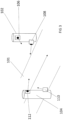
- FIG. 2 shows a vehicle imaging station according to an embodiment of the invention.
- the vehicle imaging station of Figure 2 is similar to the vehicle imaging station of Figure 1 and like parts are numbered with the same reference numerals. In the embodiment shown in Figure 2 however, the vehicle imaging station does not include a booth.
- Figure 3 shows an isometric view of the camera array according to an embodiment of the second aspect of the invention, comprising the first and second support posts 102 and 104 of Figure 1 and the first, second, third and fourth cameras 106, 108, 110, 122.
- a control unit 103 In use, as a vehicle approaches the first and second support posts 102, 104, a control unit 103 causes the second and third cameras 108, 110 to each capture an image of the front of the vehicle 122. As the vehicle moves between the support posts 102, 104, the control unit 103 causes all four cameras to capture one or more images of the sides of the vehicle 122. Then, as the vehicle 122 moves past the support posts 102, 104, the control unit 103 causes the first camera to capture one or more images of the top of the vehicle and an upper part of the back of the vehicle, and causes the fourth camera to capture one or more images of the lower part of the back of the vehicle.
- the camera array includes 4 cameras, it will be appreciated that some embodiments of the invention may include 5, 6 or more cameras.
- the array could include a fifth camera located at a third height, greater than the first and second heights, for example for capturing images of taller vehicles such as vans.
- the array could include a sixth camera which could be, for example an overhead camera located on an overhead gantry such as overhead gantry 113 shown in Figures 1 and 2 .
- the camera array may include more than one overhead camera, arranged to capture different parts of a roof of a vehicle passing underneath.
Landscapes
- Engineering & Computer Science (AREA)
- Multimedia (AREA)
- Signal Processing (AREA)
- Physics & Mathematics (AREA)
- General Physics & Mathematics (AREA)
- Theoretical Computer Science (AREA)
- Computer Vision & Pattern Recognition (AREA)
- Quality & Reliability (AREA)
- Analytical Chemistry (AREA)
- Biochemistry (AREA)
- General Health & Medical Sciences (AREA)
- Immunology (AREA)
- Pathology (AREA)
- Chemical & Material Sciences (AREA)
- Life Sciences & Earth Sciences (AREA)
- Health & Medical Sciences (AREA)
- Studio Devices (AREA)
- Closed-Circuit Television Systems (AREA)
- Fittings On The Vehicle Exterior For Carrying Loads, And Devices For Holding Or Mounting Articles (AREA)
Claims (10)
- Fahrzeugabbildungsvorrichtung (100) umfassend eine Kameraanordnung umfassend vier Kameras (106, 108, 110, 112) zur Abbildung eines Fahrzeugs (122), während es sich durch ein Fahrzeugabbildungsvolumen bewegt, wobei die Fahrzeugabbildungsvorrichtung folgendes umfasst:eine oder mehrere Stützstrukturen (102);erste (106) und zweite (108) Kameras, welche an der einen oder mehreren Stützstrukturen angebracht sind und sich an einer ersten Seite des Fahrzeugabbildungsvolumens befinden;dritte (110) und vierte (112) Kameras, welche an der einen oder mehreren Stützstrukturen angebracht sind und sich an einer zweiten Seite des Fahrzeugabbildungsvolumens, welches gegenüber der ersten Seite liegt, befinden, wobei sich die erste Kamera auf einer ersten Höhe befindet und derart angewinkelt ist um eine oder mehrere Abbildungen einer Front eines Fahrzeugs, während es in das Fahrzeugabbildungsvolumen eintritt, aufzunehmen, und wobei sich die zweite Kamera auf einer zweiten Höhe, welche größer als die erste Höhe ist, befindet und derart angewinkelt ist um eine oder mehrere Abbildungen eines Hecks eines Fahrzeugs, während es das Fahrzeugabbildungsvolumen verlässt, aufzunehmen, und die dritte Kamera sich auf der ersten Höhe befindet und derart angewinkelt ist um eine oder mehrere Abbildungen einer Front eines Fahrzeugs, während es in das Fahrzeugabbildungsvolumen eintritt, aufzunehmen und die vierte Kamera sich auf der zweiten Höhe befindet und derart angewinkelt ist um ein oder mehrere Abbildungen eines Hecks eines Fahrzeugs, während es das Fahrzeugabbildungsvolumen verlässt, aufzunehmen.
- Fahrzeugabbildungsvorrichtung (100) nach Anspruch 1, weiterhin umfassend eine fünfte Kamera, welche sich über dem Fahrzeugabbildungsvolumen befindet und derart angeordnet ist um eine oder mehrere Abbildungen von einer Oberseite eines Fahrzeugs (122), welches sich durch das Fahrzeugabbildungsvolumen bewegt, aufzunehmen.
- Fahrzeugabbildungsvorrichtung (100) nach einem der vorangegangenen Ansprüche, wobei die Fahrzeugabbildungsvorrichtung eine Fahrzeuglängen- und/oder Fahrzeughöhen- Ermittlungsvorrichtung umfasst und die Steuereinheit (103), welche die Kameras dazu veranlassen kann die Anzahl an aufzunehmende Abbildungen entsprechend einer ermittelten Länge und/oder Höhe des Fahrzeugs anzupassen.
- Fahrzeugabbildungsvorrichtung (100) nach einem der vorangegangenen Ansprüche, wobei die eine oder mehreren Kameras an einem oder mehreren Stützpfeilern (102) angebracht sind.
- Fahrzeugabbildungsvorrichtung (100) nach einem der vorangegangenen Ansprüche, weiterhin umfassend eine Kabine (116), innerhalb welcher eine oder mehrere der Kameras bereitgestellt werden und wobei die Kabine einen Einlass und einen Auslass für ein Fahrzeug (122) hat.
- Fahrzeugabbildungsvorrichtung (100) nach Anspruch 5, wobei zumindest ein Teil der Wände der Kabine (116) eine Lichtabsorptionsbeschichtung oder eine Antireflexionsbeschichtung umfasst.
- Fahrzeugabbildungsvorrichtung (100) nach Anspruch 5 oder 6, wobei die Kabine (116) an jedem Ende automatische Türen (118, 120) umfasst, welche derart angeordnet sind um sich zu öffnen und so dem Fahrzeug (122) das Eintreten in die Kabine zu ermöglichen, um sich automatisch zu schließen sobald das Fahrzeug in die Kabine eingetreten ist und sich wieder zu öffnen um dem Fahrzeug das Verlassen der Kabine zu ermöglichen.
- Fahrzeugabbildungsvorrichtung (100) nach einem der vorangegangenen Ansprüche, weiterhin umfassend ein Erfassungssystem für eindeutige Identifikatoren zum Erfassen und Verarbeiten eines oder mehrerer Abbildungen von eindeutigen Identifikatoren, die dem von der Vorrichtung abgebildeten Fahrzeug (122) zugeordnet sind.
- Fahrzeugabbildungsvorrichtung (100) nach einem der vorangegangenen Ansprüche, wobei die erste Höhe zwischen 0,6m und 1m liegt.
- Fahrzeugabbildungsvorrichtung (100) nach einem der vorangegangenen Ansprüche, wobei die zweite Höhe zwischen 1m und 1,5m liegt.
Applications Claiming Priority (2)
| Application Number | Priority Date | Filing Date | Title |
|---|---|---|---|
| GB1707968.2A GB2562722B (en) | 2017-05-18 | 2017-05-18 | Vehicle imaging apparatus |
| PCT/GB2018/051301 WO2018211251A1 (en) | 2017-05-18 | 2018-05-14 | Vehicle imaging apparatus |
Publications (3)
| Publication Number | Publication Date |
|---|---|
| EP3635947A1 EP3635947A1 (de) | 2020-04-15 |
| EP3635947C0 EP3635947C0 (de) | 2023-06-07 |
| EP3635947B1 true EP3635947B1 (de) | 2023-06-07 |
Family
ID=59220702
Family Applications (1)
| Application Number | Title | Priority Date | Filing Date |
|---|---|---|---|
| EP18725630.0A Active EP3635947B1 (de) | 2017-05-18 | 2018-05-14 | Fahrzeugbildgebungsvorrichtung |
Country Status (5)
| Country | Link |
|---|---|
| US (1) | US11303822B2 (de) |
| EP (1) | EP3635947B1 (de) |
| ES (1) | ES2952551T3 (de) |
| GB (1) | GB2562722B (de) |
| WO (1) | WO2018211251A1 (de) |
Families Citing this family (4)
| Publication number | Priority date | Publication date | Assignee | Title |
|---|---|---|---|---|
| US11461890B2 (en) | 2020-02-05 | 2022-10-04 | Fulpruf Technology Corporation | Vehicle supply chain damage tracking system |
| US12050153B2 (en) * | 2020-11-13 | 2024-07-30 | Taiwan Semiconductor Manufacturing Company Ltd. | Method for monitoring transport vehicle and maintenance thereof |
| CN114001680A (zh) * | 2021-11-01 | 2022-02-01 | 吉林大学 | 一种车辆侧墙不平度测量装置及测量方法 |
| CN115343289A (zh) * | 2022-07-18 | 2022-11-15 | 中国第一汽车股份有限公司 | 一种汽车总装整车坑包划伤自动检测系统及方法 |
Family Cites Families (17)
| Publication number | Priority date | Publication date | Assignee | Title |
|---|---|---|---|---|
| JPH01218273A (ja) * | 1988-02-26 | 1989-08-31 | Nec Home Electron Ltd | ビデオカメラ装置 |
| JPH01218272A (ja) * | 1988-02-26 | 1989-08-31 | Nec Home Electron Ltd | 電子スチルカメラ装置 |
| JPH02214830A (ja) * | 1989-02-16 | 1990-08-27 | Suminosuke Kawase | ブレ撮影を防止するカメラおよびブレ撮影にならないシャッタースピードを測定する装置 |
| JPH04185579A (ja) * | 1990-11-20 | 1992-07-02 | Toshiba Corp | 列車番号表示画像入力装置 |
| KR940003934B1 (ko) * | 1991-02-01 | 1994-05-09 | 삼성전자 주식회사 | 비데오 카메라의 자동셔터스피드 제어회로 |
| JP3681152B2 (ja) * | 1999-02-25 | 2005-08-10 | 株式会社日立国際電気 | テレビカメラの制御方法及びテレビカメラ |
| CA2326087A1 (en) * | 2000-11-16 | 2002-05-16 | Craig Summers | Inward-looking imaging system |
| CA2429236A1 (en) * | 2000-11-16 | 2002-05-23 | Vr Interactive Corporation | Inward-looking imaging system |
| CN101995756A (zh) * | 2009-08-26 | 2011-03-30 | 鸿富锦精密工业(深圳)有限公司 | 阵列摄影机系统 |
| CN102065277A (zh) * | 2009-11-12 | 2011-05-18 | 鸿富锦精密工业(深圳)有限公司 | 阵列摄影机系统 |
| GB2500716A (en) * | 2012-03-30 | 2013-10-02 | Daniel George Gould | Vehicle imaging apparatus |
| US20150097924A1 (en) * | 2012-11-30 | 2015-04-09 | Sharp Cars Detailing & More, LLC | Mobile inspection system |
| TWI542194B (zh) * | 2014-07-02 | 2016-07-11 | 坦億有限公司 | 立體影像處理系統、裝置與方法 |
| CN105323572A (zh) * | 2014-07-10 | 2016-02-10 | 坦亿有限公司 | 立体影像处理系统、装置与方法 |
| KR20160040039A (ko) * | 2014-10-02 | 2016-04-12 | (주) 키움소프트 | 차량 외관형상 모델링 장치 및 모델링 방법 |
| US10063758B2 (en) | 2014-10-03 | 2018-08-28 | Davo Scheich | Vehicle photographic tunnel |
| KR101625538B1 (ko) * | 2015-07-16 | 2016-06-13 | 비원이미지 주식회사 | 도시방범이 가능한 다차선 자동차 번호판 인식시스템 |
-
2017
- 2017-05-18 GB GB1707968.2A patent/GB2562722B/en not_active Expired - Fee Related
-
2018
- 2018-05-14 WO PCT/GB2018/051301 patent/WO2018211251A1/en not_active Ceased
- 2018-05-14 ES ES18725630T patent/ES2952551T3/es active Active
- 2018-05-14 EP EP18725630.0A patent/EP3635947B1/de active Active
- 2018-05-14 US US16/613,880 patent/US11303822B2/en active Active
Also Published As
| Publication number | Publication date |
|---|---|
| US11303822B2 (en) | 2022-04-12 |
| US20200084393A1 (en) | 2020-03-12 |
| ES2952551T3 (es) | 2023-11-02 |
| EP3635947C0 (de) | 2023-06-07 |
| EP3635947A1 (de) | 2020-04-15 |
| GB2562722A (en) | 2018-11-28 |
| WO2018211251A1 (en) | 2018-11-22 |
| GB201707968D0 (en) | 2017-07-05 |
| GB2562722B (en) | 2019-07-31 |
Similar Documents
| Publication | Publication Date | Title |
|---|---|---|
| EP3635947B1 (de) | Fahrzeugbildgebungsvorrichtung | |
| US10839527B2 (en) | Method and device of measuring infrared spectral characteristics of moving target | |
| US20100238290A1 (en) | Drive over vehicle inspection systems and methods | |
| US11061122B2 (en) | High-definition map acquisition system | |
| TR201910987T4 (tr) | Tren tipi tanımlama yöntemi ve sistemi ile güvenlik denetim yöntemi ve sistemi. | |
| US11483484B2 (en) | Systems and methods for imaging of moving objects using multiple cameras | |
| CN103481910A (zh) | 列车零部件图像采集系统及列车零部件异常检测系统 | |
| DE102015122183B4 (de) | Vorrichtung und Verfahren für ein unbemanntes Flugobjekt | |
| CN106546257A (zh) | 车距测量方法及装置、车辆相对速度测量方法及装置 | |
| EP3234683B1 (de) | Bildgebungssystem | |
| CN105933611A (zh) | 轨道异物侵限识别中防摄像头抖动的动态包络线绘制方法 | |
| CN113689505A (zh) | 一种基于定位信息调整车载摄像头曝光参数的方法及装置 | |
| CN104917957A (zh) | 用于控制摄像机成像的设备及其系统 | |
| WO2020234089A1 (en) | Automatic damage detection for cars | |
| KR101996368B1 (ko) | 영상 처리를 이용한 차량 속도 측정 방법 및 장치 | |
| US20180373136A1 (en) | Aerial photography camera system | |
| WO2015197641A1 (de) | Bestimmung mindestens eines merkmals eines fahrzeugs | |
| KR102144249B1 (ko) | 기준 측정물을 이용한 차량 속도 캘리브레이션 방법 및 장치 | |
| US20060078164A1 (en) | Measurement method using blurred images | |
| US20050072902A1 (en) | Method and device for evaluating a parameter of a moving object | |
| EP3349201A1 (de) | Einparkassistenzverfahren und fahrzeugeinparkassistenzsystem | |
| US20240230473A9 (en) | System and method for automatic inspection of vehicles | |
| DE102012012026A1 (de) | Verfahren und Vorrichtung zur optischen Beobachtung von Personen hinter Glassscheiben in Fahrzeugen auf große Distanz mit Erkennung der Gesichter und Datenabgleich | |
| CN114998727A (zh) | 跑道异物检测方法、装置及系统 | |
| CN118731966B (zh) | 多相机融合单线束激光雷达的车道查验方法及查验设备 |
Legal Events
| Date | Code | Title | Description |
|---|---|---|---|
| STAA | Information on the status of an ep patent application or granted ep patent |
Free format text: STATUS: UNKNOWN |
|
| STAA | Information on the status of an ep patent application or granted ep patent |
Free format text: STATUS: THE INTERNATIONAL PUBLICATION HAS BEEN MADE |
|
| PUAI | Public reference made under article 153(3) epc to a published international application that has entered the european phase |
Free format text: ORIGINAL CODE: 0009012 |
|
| STAA | Information on the status of an ep patent application or granted ep patent |
Free format text: STATUS: REQUEST FOR EXAMINATION WAS MADE |
|
| 17P | Request for examination filed |
Effective date: 20191209 |
|
| AK | Designated contracting states |
Kind code of ref document: A1 Designated state(s): AL AT BE BG CH CY CZ DE DK EE ES FI FR GB GR HR HU IE IS IT LI LT LU LV MC MK MT NL NO PL PT RO RS SE SI SK SM TR |
|
| AX | Request for extension of the european patent |
Extension state: BA ME |
|
| DAV | Request for validation of the european patent (deleted) | ||
| DAX | Request for extension of the european patent (deleted) | ||
| GRAP | Despatch of communication of intention to grant a patent |
Free format text: ORIGINAL CODE: EPIDOSNIGR1 |
|
| STAA | Information on the status of an ep patent application or granted ep patent |
Free format text: STATUS: GRANT OF PATENT IS INTENDED |
|
| RIC1 | Information provided on ipc code assigned before grant |
Ipc: G03B 15/00 20060101ALI20220329BHEP Ipc: G01N 21/88 20060101ALI20220329BHEP Ipc: H04N 5/222 20060101ALI20220329BHEP Ipc: H04N 5/247 20060101AFI20220329BHEP |
|
| INTG | Intention to grant announced |
Effective date: 20220426 |
|
| RIN1 | Information on inventor provided before grant (corrected) |
Inventor name: GOULD, DANIEL GEORGE |
|
| GRAJ | Information related to disapproval of communication of intention to grant by the applicant or resumption of examination proceedings by the epo deleted |
Free format text: ORIGINAL CODE: EPIDOSDIGR1 |
|
| STAA | Information on the status of an ep patent application or granted ep patent |
Free format text: STATUS: REQUEST FOR EXAMINATION WAS MADE |
|
| GRAP | Despatch of communication of intention to grant a patent |
Free format text: ORIGINAL CODE: EPIDOSNIGR1 |
|
| STAA | Information on the status of an ep patent application or granted ep patent |
Free format text: STATUS: GRANT OF PATENT IS INTENDED |
|
| INTC | Intention to grant announced (deleted) | ||
| INTG | Intention to grant announced |
Effective date: 20220922 |
|
| GRAS | Grant fee paid |
Free format text: ORIGINAL CODE: EPIDOSNIGR3 |
|
| GRAA | (expected) grant |
Free format text: ORIGINAL CODE: 0009210 |
|
| STAA | Information on the status of an ep patent application or granted ep patent |
Free format text: STATUS: THE PATENT HAS BEEN GRANTED |
|
| AK | Designated contracting states |
Kind code of ref document: B1 Designated state(s): AL AT BE BG CH CY CZ DE DK EE ES FI FR GB GR HR HU IE IS IT LI LT LU LV MC MK MT NL NO PL PT RO RS SE SI SK SM TR |
|
| REG | Reference to a national code |
Ref country code: GB Ref legal event code: FG4D |
|
| REG | Reference to a national code |
Ref country code: CH Ref legal event code: EP Ref country code: AT Ref legal event code: REF Ref document number: 1578207 Country of ref document: AT Kind code of ref document: T Effective date: 20230615 |
|
| REG | Reference to a national code |
Ref country code: DE Ref legal event code: R096 Ref document number: 602018051004 Country of ref document: DE |
|
| U01 | Request for unitary effect filed |
Effective date: 20230613 |
|
| U07 | Unitary effect registered |
Designated state(s): AT BE BG DE DK EE FI FR IT LT LU LV MT NL PT SE SI Effective date: 20230621 |
|
| REG | Reference to a national code |
Ref country code: LT Ref legal event code: MG9D |
|
| PG25 | Lapsed in a contracting state [announced via postgrant information from national office to epo] |
Ref country code: NO Free format text: LAPSE BECAUSE OF FAILURE TO SUBMIT A TRANSLATION OF THE DESCRIPTION OR TO PAY THE FEE WITHIN THE PRESCRIBED TIME-LIMIT Effective date: 20230907 |
|
| REG | Reference to a national code |
Ref country code: ES Ref legal event code: FG2A Ref document number: 2952551 Country of ref document: ES Kind code of ref document: T3 Effective date: 20231102 |
|
| PG25 | Lapsed in a contracting state [announced via postgrant information from national office to epo] |
Ref country code: RS Free format text: LAPSE BECAUSE OF FAILURE TO SUBMIT A TRANSLATION OF THE DESCRIPTION OR TO PAY THE FEE WITHIN THE PRESCRIBED TIME-LIMIT Effective date: 20230607 Ref country code: HR Free format text: LAPSE BECAUSE OF FAILURE TO SUBMIT A TRANSLATION OF THE DESCRIPTION OR TO PAY THE FEE WITHIN THE PRESCRIBED TIME-LIMIT Effective date: 20230607 Ref country code: GR Free format text: LAPSE BECAUSE OF FAILURE TO SUBMIT A TRANSLATION OF THE DESCRIPTION OR TO PAY THE FEE WITHIN THE PRESCRIBED TIME-LIMIT Effective date: 20230908 |
|
| PG25 | Lapsed in a contracting state [announced via postgrant information from national office to epo] |
Ref country code: SK Free format text: LAPSE BECAUSE OF FAILURE TO SUBMIT A TRANSLATION OF THE DESCRIPTION OR TO PAY THE FEE WITHIN THE PRESCRIBED TIME-LIMIT Effective date: 20230607 |
|
| PG25 | Lapsed in a contracting state [announced via postgrant information from national office to epo] |
Ref country code: IS Free format text: LAPSE BECAUSE OF FAILURE TO SUBMIT A TRANSLATION OF THE DESCRIPTION OR TO PAY THE FEE WITHIN THE PRESCRIBED TIME-LIMIT Effective date: 20231007 |
|
| PG25 | Lapsed in a contracting state [announced via postgrant information from national office to epo] |
Ref country code: SM Free format text: LAPSE BECAUSE OF FAILURE TO SUBMIT A TRANSLATION OF THE DESCRIPTION OR TO PAY THE FEE WITHIN THE PRESCRIBED TIME-LIMIT Effective date: 20230607 Ref country code: SK Free format text: LAPSE BECAUSE OF FAILURE TO SUBMIT A TRANSLATION OF THE DESCRIPTION OR TO PAY THE FEE WITHIN THE PRESCRIBED TIME-LIMIT Effective date: 20230607 Ref country code: RO Free format text: LAPSE BECAUSE OF FAILURE TO SUBMIT A TRANSLATION OF THE DESCRIPTION OR TO PAY THE FEE WITHIN THE PRESCRIBED TIME-LIMIT Effective date: 20230607 Ref country code: IS Free format text: LAPSE BECAUSE OF FAILURE TO SUBMIT A TRANSLATION OF THE DESCRIPTION OR TO PAY THE FEE WITHIN THE PRESCRIBED TIME-LIMIT Effective date: 20231007 Ref country code: CZ Free format text: LAPSE BECAUSE OF FAILURE TO SUBMIT A TRANSLATION OF THE DESCRIPTION OR TO PAY THE FEE WITHIN THE PRESCRIBED TIME-LIMIT Effective date: 20230607 |
|
| PG25 | Lapsed in a contracting state [announced via postgrant information from national office to epo] |
Ref country code: PL Free format text: LAPSE BECAUSE OF FAILURE TO SUBMIT A TRANSLATION OF THE DESCRIPTION OR TO PAY THE FEE WITHIN THE PRESCRIBED TIME-LIMIT Effective date: 20230607 |
|
| REG | Reference to a national code |
Ref country code: DE Ref legal event code: R097 Ref document number: 602018051004 Country of ref document: DE |
|
| PLBE | No opposition filed within time limit |
Free format text: ORIGINAL CODE: 0009261 |
|
| STAA | Information on the status of an ep patent application or granted ep patent |
Free format text: STATUS: NO OPPOSITION FILED WITHIN TIME LIMIT |
|
| 26N | No opposition filed |
Effective date: 20240308 |
|
| U20 | Renewal fee for the european patent with unitary effect paid |
Year of fee payment: 7 Effective date: 20240517 |
|
| REG | Reference to a national code |
Ref country code: CH Ref legal event code: PL |
|
| PG25 | Lapsed in a contracting state [announced via postgrant information from national office to epo] |
Ref country code: MC Free format text: LAPSE BECAUSE OF FAILURE TO SUBMIT A TRANSLATION OF THE DESCRIPTION OR TO PAY THE FEE WITHIN THE PRESCRIBED TIME-LIMIT Effective date: 20230607 |
|
| PG25 | Lapsed in a contracting state [announced via postgrant information from national office to epo] |
Ref country code: MC Free format text: LAPSE BECAUSE OF FAILURE TO SUBMIT A TRANSLATION OF THE DESCRIPTION OR TO PAY THE FEE WITHIN THE PRESCRIBED TIME-LIMIT Effective date: 20230607 Ref country code: CH Free format text: LAPSE BECAUSE OF NON-PAYMENT OF DUE FEES Effective date: 20240531 |
|
| PG25 | Lapsed in a contracting state [announced via postgrant information from national office to epo] |
Ref country code: IE Free format text: LAPSE BECAUSE OF NON-PAYMENT OF DUE FEES Effective date: 20240514 |
|
| U20 | Renewal fee for the european patent with unitary effect paid |
Year of fee payment: 8 Effective date: 20250529 |
|
| PGFP | Annual fee paid to national office [announced via postgrant information from national office to epo] |
Ref country code: GB Payment date: 20250516 Year of fee payment: 8 |
|
| PG25 | Lapsed in a contracting state [announced via postgrant information from national office to epo] |
Ref country code: CY Free format text: LAPSE BECAUSE OF FAILURE TO SUBMIT A TRANSLATION OF THE DESCRIPTION OR TO PAY THE FEE WITHIN THE PRESCRIBED TIME-LIMIT; INVALID AB INITIO Effective date: 20180514 |
|
| PG25 | Lapsed in a contracting state [announced via postgrant information from national office to epo] |
Ref country code: HU Free format text: LAPSE BECAUSE OF FAILURE TO SUBMIT A TRANSLATION OF THE DESCRIPTION OR TO PAY THE FEE WITHIN THE PRESCRIBED TIME-LIMIT; INVALID AB INITIO Effective date: 20180514 |
|
| PGFP | Annual fee paid to national office [announced via postgrant information from national office to epo] |
Ref country code: ES Payment date: 20250630 Year of fee payment: 8 |