EP3635751B1 - Procédé et système de modification de surface d'un substrat destiné à une cible de faisceau ionique - Google Patents
Procédé et système de modification de surface d'un substrat destiné à une cible de faisceau ionique Download PDFInfo
- Publication number
- EP3635751B1 EP3635751B1 EP17912902.8A EP17912902A EP3635751B1 EP 3635751 B1 EP3635751 B1 EP 3635751B1 EP 17912902 A EP17912902 A EP 17912902A EP 3635751 B1 EP3635751 B1 EP 3635751B1
- Authority
- EP
- European Patent Office
- Prior art keywords
- target
- source layer
- neutron source
- neutron
- target substrate
- Prior art date
- Legal status (The legal status is an assumption and is not a legal conclusion. Google has not performed a legal analysis and makes no representation as to the accuracy of the status listed.)
- Active
Links
Images



Classifications
-
- G—PHYSICS
- G21—NUCLEAR PHYSICS; NUCLEAR ENGINEERING
- G21K—HANDLING OF PARTICLES OR IONISING RADIATION NOT OTHERWISE PROVIDED FOR; IRRADIATION DEVICES; GAMMA RAY OR X-RAY MICROSCOPES
- G21K1/00—Arrangements for handling particles or ionising radiation, e.g. focusing or moderating
-
- A—HUMAN NECESSITIES
- A61—MEDICAL OR VETERINARY SCIENCE; HYGIENE
- A61N—ELECTROTHERAPY; MAGNETOTHERAPY; RADIATION THERAPY; ULTRASOUND THERAPY
- A61N5/00—Radiation therapy
- A61N5/10—X-ray therapy; Gamma-ray therapy; Particle-irradiation therapy
-
- G—PHYSICS
- G21—NUCLEAR PHYSICS; NUCLEAR ENGINEERING
- G21G—CONVERSION OF CHEMICAL ELEMENTS; RADIOACTIVE SOURCES
- G21G4/00—Radioactive sources
- G21G4/02—Neutron sources
-
- G—PHYSICS
- G21—NUCLEAR PHYSICS; NUCLEAR ENGINEERING
- G21K—HANDLING OF PARTICLES OR IONISING RADIATION NOT OTHERWISE PROVIDED FOR; IRRADIATION DEVICES; GAMMA RAY OR X-RAY MICROSCOPES
- G21K5/00—Irradiation devices
- G21K5/04—Irradiation devices with beam-forming means
-
- A—HUMAN NECESSITIES
- A61—MEDICAL OR VETERINARY SCIENCE; HYGIENE
- A61N—ELECTROTHERAPY; MAGNETOTHERAPY; RADIATION THERAPY; ULTRASOUND THERAPY
- A61N5/00—Radiation therapy
- A61N5/10—X-ray therapy; Gamma-ray therapy; Particle-irradiation therapy
- A61N2005/1085—X-ray therapy; Gamma-ray therapy; Particle-irradiation therapy characterised by the type of particles applied to the patient
- A61N2005/109—Neutrons
Definitions
- the present disclosure generally relates to design and making method of a neutron generating target which can be used in boron neutron capture therapy.
- Neutron sources have many potential applications, including medical treatments, isotope production, explosive/fissile materials detection, assaying of precious metal ores, imaging, and others.
- a particular area of interest is boron neutron capture therapy (BNCT), which is a cancer treatment technique in which boron is preferentially concentrated in a patient's malignant tumor and a neutron beam is aimed through the patient at the boron-containing tumor.
- BNCT boron neutron capture therapy
- the boron atoms capture a neutron, particles are produced having sufficient energy to cause severe damage to the tissue in which it is present.
- the effect is highly localized, and, as a result, this technique can be used as a highly selective cancer treatment method, effecting only specifically targeted cells.
- An apparatus can include a rotary fixture with a coolant inlet and a coolant outlet, and a plurality of neutron-producing segments.
- Each neutron-producing segment of the plurality of neutron-producing segments is removably coupled to the rotary fixture, and includes a substrate having a coolant channel circuit defined therein and a solid neutron source layer disposed thereon.
- the coolant channel circuits are in fluid communication with the coolant inlet and the coolant outlet.
- EP2874473A1 discloses a target for a neutron-generating device and a method for manufacturing the target therefor.
- the target is for a neutron-generating device and includes: a metal substrate retaining a target material; and a metal thin film for sealing that holds the target material at a retention surface side.
- the retention surface side of the metal substrate includes: a frame portion; and an embossed structure including: a plurality of island portions that are surrounded by the frame portion; and the rest recessed portion that is created by decreasing a thickness of a region other than the frame portion and the island portions by a thickness of the target material.
- the metal thin film and surfaces of the frame portion and the island portions are subjected to hot isostatic pressing (HIP) bonding to seal the target material onto the recessed portion by using the metal thin film.
- HIP hot isostatic pressing
- the substrate is first cleaned, both chemically and by off-sputtering in a vacuum chamber.
- vapor deposition by a sublimator or vaporizer first coats a cooled shroud disposed around the substrate with a thin film of hydride forming metal which getters any contaminant gas molecules.
- a shutter is then opened to allow hydride forming metal to be deposited as a film or coating on the substrate.
- the present disclosure relates to a method for making a neutron generating target.
- the method can include modifying a surface of a target substrate to form one or more surface features.
- the method can also include disposing a neutron source layer on the surface of the target substrate.
- the method can include a material removal process or a material addition process.
- the material removal process can include abrasive blasting, etching, or polishing.
- the material addition process can include vacuum deposition, plating, or printing.
- the target substrate can include at least one of copper, aluminum, titanium, molybdenum, and stainless steel.
- the neutron source layer can include at least one of lithium, beryllium, and carbon.
- the neutron source layer can be pressed on the surface of the target substrate. In some embodiments, the neutron source layer can be deposited on the surface of the target substrate by evaporation.
- the method can include heating the neutron source layer and the target substrate to an elevated temperature for a duration of time for form a bond between the neutron source layer and the target substrate.
- the elevated temperature can be between about 100 degrees Celsius and about 500 degrees Celsius.
- the duration of time can be between about 0.1 hours and 10 hours.
- the method can also include modifying a top surface of the neutron source layer to form one or more surface features.
- the present disclosure also relates to a neutron generating target.
- the target can include a target substrate having an uneven surface.
- the uneven surface can include one or more surface features.
- the target can also include a neutron source layer disposed on the surface of the target substrate and bonded to the target substrate.
- the one or more surface features can be recessed into the target substrate.
- the one or more surface features can have a depth of between about 1 micron and about 50 microns.
- the one or more surface features can protrude from the target substrate.
- the one or more surface features can have a height of between about 1 micron and about 50 microns.
- the one or more surface features can include a plurality of surface features with an average pitch of between about 1 micron and about 50 microns.
- the target substrate can include at least one of copper, aluminum, titanium, molybdenum, and stainless steel.
- the neutron source layer can include at least one of lithium, beryllium, and carbon.
- the neutron source layer can have a thickness of between about 10 microns and about 500 microns.
- FIGS. 1-5 Specific embodiments of the present disclosure are described below and shown in FIGS. 1-5 . These embodiments are being presented by way of example only. Numerous modifications and other embodiments are within the scope of one of ordinary skill in the art and are contemplated as falling within the scope of the present disclosure. In addition, those skilled in the art should appreciate that the specific conditions and configurations are exemplary and that actual conditions and configurations will depend on the specific system. Those skilled in the art will also be able to recognize and identify equivalents to the specific elements shown, using no more than routine experimentation.
- the present disclosure relates to design and manufacture method of a neutron generating target which can be used in boron neutron capture therapy (BNCT).
- BNCT boron neutron capture therapy
- BNCT is a targeted radiation therapy for cancer treatment during which a patient is infused with a boron rich solution such as fructose-BPA.
- the boron is then selectively absorbed by the cancer cells, e.g., at a tumor site.
- Neutrons for example, generated by a lithium neutron source, interact with the boron by the nuclear reaction: 10 B+n th ⁇ [ 11 B]* ⁇ + 7 Li+2.31 MeV.
- the cancer cells are killed by the alpha particles and lithium ions.
- the alpha particles and lithium ions released have very short ranges, for example about 5-9 microns, and thus are similar in size to a cancer cell.
- BNCT treatment requires a high flux of epithermal neutrons, typically between 1 eV and 10 keV. Fluxes required for clinical treatments are on the order of 1 ⁇ 10 9 n/cm 2 /s. Historically, BNCT treatments have been performed at nuclear research reactor facilities, however accelerator-based neutron sources are preferred for widespread implementation of the treatment in hospital environments.
- the proton beam size can be of comparable size or smaller size than the neutron beam at the exit of the beam shaping assembly.
- the proton beam size can be between about 20 mm and about 150 mm.
- the “near threshold” approach has the advantage that the neutron energy distribution from the target is close to the epithermal energy distribution for treatment, thus only minimal moderation can be used.
- the “above threshold” approach produces a higher energy distribution of neutrons, and therefore can use more moderation, but takes advantage of a large peak in the reaction cross section at about 2.3 MeV resulting in a much higher initial yield of neutrons.
- a rotatable structure such as a disk or a drum includes a plurality of segmented target "petals” (also referred to herein as “segments”) attached to a central hub (also referred to herein as a "rotary fixture"), where each petal is directly cooled via its own dedicated micro-channels.
- the plurality of target petals collectively, may be said to constitute a target.
- Each petal can include a substrate and a solid neutron source layer disposed on a surface of the substrate.
- An exemplary system includes 16 petals on a planar rotatable structure, each petal occupying 22.5 degrees of a circumference of the rotatable structure, with the rotatable structure having an outer diameter (OD) of about 1 meter, and a semi-continuous strip of lithium deposited on the petals 0.14 meters in the radial direction centered on a 0.84 meter diameter.
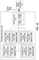
- FIG. 1A is a block diagram of an apparatus suitable for use in BNCT, in accordance with some embodiments of the present disclosure.
- a rotatable structure 102 includes a plurality of target petals or segments 104A-104D, and each segment of the plurality of segments 104A-104D has a corresponding substrate 106A-106D coupled to a corresponding neutron source layer 108A-108D.
- the neutron source layer(s) 108A-108D can include solid lithium.
- One or more of the substrates 106A-106D includes a corresponding coolant channel (110A-110D), such as a micro-channel, for actively cooling the associated substrate and/or neutron source layer (e.g., to maintain the neutron source layer 108A-108D in solid form).
- the segments 104A-104D are optionally coupled to a rotary fixture 112 having an inlet 112A and an outlet 112B for conducting a coolant fluid.
- the segments 104A-104D can be coupled to the rotary fixture 112 via one or more of: screws, bolts, quick-disconnect fittings, clamps, and/or the like.
- the coolant fluid can include one or more of: water (e.g., deionized water, which provides higher heat capacity and thermal conductivity than oils, and lower corrosive activity as compared with city water), glycol, a glycol/water mixture, heat transfer oils (e.g., to avoid possible water / lithium interaction during a failure), "Galinstan” (a commercial liquid gallium/indium/tin mixture), liquid nitrogen, and/or other coolants.
- the rotary fixture 112 can be configured to couple to an external spindle assembly and/or drive motor via a coupling such as a rotary water seal and/or a rotary vacuum seal.
- FIG. 1A also depicts a proton beam generator 113 and a proton beam 113A.
- Each segment of the segments 104A-104D can have a shape that is one of: a portion of an annulus, a pie-shape or "sector" (defined as the plane figure enclosed by two radii of a circle or ellipse and the arc between them), a truncated sector (i.e., a portion of a sector), a square, and a rectangle.
- the neutron source layer 108A-108D can include lithium, beryllium, or another suitable neutron source in solid form and at a thickness that is sufficient to produce the desired neutron flux, for example for lithium at least about 10 ⁇ m, or at least about 90 ⁇ m (e.g., about 400 ⁇ m), or between about 10 ⁇ m and about 200 ⁇ m, or between about 90 ⁇ m and about 150 ⁇ m.
- lithium at least about 10 ⁇ m, or at least about 90 ⁇ m (e.g., about 400 ⁇ m), or between about 10 ⁇ m and about 200 ⁇ m, or between about 90 ⁇ m and about 150 ⁇ m.
- the neutron source layer 108A-108D can be adhered to the substrates 106A-106D of the segments 104A-104D via a thermal bond.
- one or more of the substrates 106A-106D include copper, and a lithium neutron source layer 108A-108D is bonded to the one or more copper substrates 106A-106D via a pressure and temperature method.
- lithium is a reactive metal, it can form an amalgam with the copper.
- a low thermal resistance between the copper and the lithium is formed.
- the protons are deposited in the lithium during use, as opposed to the copper that underlies the lithium.
- the neutron source layer 108A-108D can change during irradiation, for example becoming more brittle and/or different in color, however as long as it remains intact and produces the same or nearly the same neutron yield, it is suitable for use.
- the neutron source layer 108A-108D can be evaporated onto the substrates 106A-106D in a thin layer, for example of about 100 microns.
- a very thin, blister-resistant middle layer can be included in such designs as well (as has done in the stationary targets, described above).
- the base petal or substrate can be made of copper or aluminum. Even materials such as stainless steel, titanium, and molybdenum are possible since the distributed heat power is so much lower than in the stationary case.
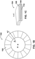
- FIG. 1B is a diagram of a plan view of a disk-shaped rotatable structure, in accordance with some embodiments.
- the rotatable structure 102 has a central hub portion "H" with a plurality of segments 104 attached thereto and emanating therefrom.
- the segments 104 each include a corresponding neutron source layer with a major surface that can be, for example, substantially normal to an axis of rotation of the rotatable structure 102.
- the axis of rotation may be defined as an axis that passes through the center of the hub "H" and is substantially normal thereto.
- FIG. 1C is a diagram showing a cross-sectional view of the rotatable structure of FIG. 1B , corresponding to line A-A' of FIG. 1B .
- a neutron source layer 108 is disposed on a substrate 106 with an embedded coolant channel 110.
- FIG. 1D is a diagram of the rotatable structure of FIG. 1B during use as part of boron neutron capture therapy (BNCT), in accordance with some embodiments.
- the rotatable structure 102 is rotating about its axis of rotation, and a proton beam generator 113 emits a proton beam 113 toward the rotatable structure 102 such that the proton beam 113A contacts a surface of the rotatable structure 102, e.g., at a neutron source layer of a segment 104.
- BNCT boron neutron capture therapy
- the proton beam 113A can be stationary (e.g., at a predetermined position) or rastering over a predetermined region of the rotatable structure 102, where the predetermined region may be fixed or may change over time.
- the proton beam 113A can form an angle with the contacting surface of the rotatable structure 102, for example of about 90.degree.. Since the rotatable structure 102 is rotating, segments 104 of the rotatable structure 102 can be sequentially contacted by the proton beam 113A.
- a neutron beam 113B is generated and directed (e.g., via a collimator or other beam-shaping structure) towards a treatment area of a patient P.
- One major failure mode of the neutron generating target in the art is hydrogen impregnation within the target.
- the hydrogen deposited in the target may damage the target materials, cause blistering of the target, limit the lifetime of the target, and necessitate servicing of the target prior to failure.
- Blistering is material damage (e.g., delamination, exfoliation, bubble, etc.) in the target due to internal hydrogen pressure exceeding the strength of the target material.
- the depth where the protons stop depends on the energy of the proton and the neutron source material. For example, in a target with a thick lithium neutron source layer (about 400 ⁇ m) bonded to a copper substrate, a 2.6 MeV proton beam may be stopped in the lithium layer.
- the proton beam may be stopped in the copper layer.
- a thinner lithium neutron source layer between about 100 ⁇ m and about 200 ⁇ m
- the proton beam may be stopped in the copper layer.
- the hydrogen concentration reached a point where internal pressure exceeds the strength of the material, a blistering might happen.
- the blistering can happen in the lithium layer or in the copper layer.
- the present disclosure provides a target design which significantly reduces target blistering failure.
- the surface of the target substrate is substantially flat and neutron source materials are bonded on the top surface of the target substrate. Protons with similar energies will stop in the target at a same depth. As a result, hydrogen concentration may become high at this depth and lead to target damage.
- the present disclosure shows a different target design where the surface of the target substrate is modified.
- the target substrate can be copper, aluminum, titanium, stainless steel, or other metals.
- the goal of the surface modification is to increase the roughness of the target substrate.
- the target substrate can be modified with a material removal process.
- the substrate can be modified with abrasive blasting.
- Different blasting media can be used in accordance with roughness requirements and substrate materials.
- the blasting media can be sand, silicon dioxide, metal shot, etc.
- the substrate can also be modified by etching or polishing.
- the target substrate can also be modified with a material addition process.
- a thin layer of material can be added to the target substrate surface by vacuum deposition, plating, printing, or other techniques.
- the material to be added can be copper, aluminum, titanium, stainless steel, or other metals.
- the roughness or features created on the substrate surface can be periodic or non-periodic.
- the average pitch of the features can be between about 1 ⁇ m and about 10 ⁇ m.
- the depth/height of the features can be between about 5 ⁇ m and about 20 ⁇ m.
- FIGS. 2A-2B shows cross-section views of targets according to some embodiments of the present disclosure.
- target substrate 202 can be modified to have periodic surface features with a fixed pitch.
- target substrate 205 can be modified to have non-periodic surface features.
- the average pitch of the surface features can be between 1 ⁇ m and 10 ⁇ m.
- the height of the surface features can be between 5 ⁇ m and 20 ⁇ m.
- the target substrate can be cleaned thoroughly to remove any debris.
- a neutron source layer can be disposed on the target substrate.
- the neutron source layer can be lithium, beryllium, graphite (carbon), or other materials, depending on different neutron producing reactions.
- the neutron source layer can be disposed onto the target substrate surface by pressing, evaporation, or other methods, to make sure the neutron source layer has a close contact with the target substrate surface.
- lithium can be pressed onto the substrate.
- the thickness of the lithium layer can be about 100 ⁇ m to about 200 ⁇ m for a neutron producing reaction with a proton energy of between about 2 MeV and about 3 MeV.
- the assembly of target substrate and neutron source layer can be heated to an elevated temperature.
- the heating can be performed with a hot-plate, a thermal chamber, or other equipment which can provide heating power.
- the heating can be performed in an inert environment, such as in an argon filled glove-box.
- the heating temperature and time duration can differ depending on the substrate material and the neutron source material. For example, for a target with lithium on a copper substrate, heating for 4 hours at 200 °C can form a good thermal and mechanical bond between the lithium and the copper. The lithium can form an amalgam with the copper, resulting in a low thermal resistance.
- the heating procedure may not be necessary. For example, if the lithium neutron source layer is deposited on the target substrate by evaporation, the heating can be skipped because there can be a good bond between the lithium and the target substrate formed during the deposition.
- a neutron source layer 203 can be disposed on the surface of target substrate 202.
- the whole target assembly 201 can be heated to an elevated temperature to form a good bond between the neutron source layer 203 and target substrate 202.
- a neutron source layer 206 can be disposed on the surface of target substrate 205 and the whole target assembly 204 can be heated to an elevated temperature to form a good bond between the neutron source layer 206 and target substrate 205.
- An advantage of the target design with substrate surface modification described herein over the existing design in the art is that protons will not stop in the target uniformly because of the roughness of the substrate. As a result, the hydrogen will not be concentrated at a same depth. This design can reduce blistering and material exfoliation in the target.
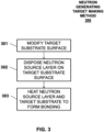
- FIG. 3 shows a flow chart describing a neutron generating target making method 300 according to some embodiments of the present disclosure.
- the method 300 starts with step 301 where a surface of a target substrate can be modified, either by a material removal process or a material addition process.
- the material removal process can include abrasive blasting, etching, or polishing.
- the material addition process can include vacuum deposition, plating, or printing.
- a neutron source layer can be disposed on the surface of the target substrate by pressing, evaporation, or other techniques.
- step 303 the whole assembly of the neutron source layer and the target substrate can be heated to an elevated temperature for a duration of time to form a good thermal and mechanical bond.
- FIG. 4 shows a flow chart describing a neutron generating target making method 400 according to some embodiments of the present disclosure.
- the method 400 starts with step 401 where a neutron source layer can be disposed on a target substrate.
- the neutron source layer can be pressed onto the target substrate.
- the neutron source layer can be deposited on the target substrate by evaporation.
- the neutron source layer can be bonded to the target substrate. For example, if the neutron source layer is pressed onto the target substrate, the neutron source layer and the target substrate can be heated to an elevated temperature for a duration of time to form a bond. If the neutron source layer is deposited by evaporation, the heating procedure can be skipped.
- a top surface of the neutron source layer can be modified to form one or more surface features.
- the modification can be a material removal process which can include abrasive blasting, etching, or polishing.
- the modification can be a material addition process which can include vacuum deposition, plating, or printing.
- the method 400 can create roughness on the neutron source layer surface, which can lead to variations in stopping depth of the protons so that the hydrogen concentration can be reduced. As a result, target blistering can be prevented.
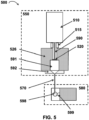
- BNCT system 500 includes neutron generating system 550 and patient positioning and treatment system 580.
- Neutron generating system 550 includes proton beam generator 510 and neutron source target 520, which is provided on a rotatable structure (not shown). Any of the rotatable structures of the present disclosure and described above can be used.
- Proton beam generator 510 can be provided in a variety of different positions relative to neutron source target 520, depending upon, for example, the size and design of the facility in which they are placed.
- Various known bending or focusing magnets can be used to direct the generated proton beam to the target.
- Proton beam 590 produced by proton beam generator 510, passes through beam transport system 515, which may include, for example, various types of focusing magnets, and reacts with neutron source target 520, thereby generating neutrons, which are generally produced in multiple directions around the source depending on their energy-higher energy neutrons moving forward from the target and lower energy neutrons scattering perpendicular to or back from the source.
- beam transport system 515 may include, for example, various types of focusing magnets, and reacts with neutron source target 520, thereby generating neutrons, which are generally produced in multiple directions around the source depending on their energy-higher energy neutrons moving forward from the target and lower energy neutrons scattering perpendicular to or back from the source.
- neutron generating system 550 further includes reflector 526, beam moderator 591, and beam collimator 592.
- neutron beam reflector, moderator, or beam collimator/delimiter known in the art can be used, and each can be positioned around the target as desired in order to capture neutrons having the desired energy range.
- reflector 526 can be positioned around the sides and behind the target, as shown in FIG. 5 , and can comprise any material known in the art that is relatively non-absorbent to neutrons, such as high atomic number material (including lead, bismuth, or alumina), or carbonaceous materials (including graphite). In this way, low energy back-scattered neutrons are reflected back into the system, thereby protecting or shielding surrounding components as well as patient 599.
- the forward-directed, relatively higher energy neutrons can be captured by moderator 591 (also comprising materials that are relatively non-absorbent to neutrons), in order to reduce their energy to a desired epithermal range.
- moderator 591 also comprising materials that are relatively non-absorbent to neutrons
- neutrons having an initial energy of approximately 500 keV can be reduced to a final energy of from about 1 eV to about 10 keV, which is a range desirable for BNCT treatment.
- Suitable moderator materials are known in the art and include, for example, D 2 O, MgF, LiF, AlF 3 , Al, Teflon, and mixtures thereof.
- beam collimator 592 can be positioned after moderator 591 to produce and focus the desired neutron beam onto target 598 in patient 599.
- BNCT system 500 further includes patient positioning and treatment system 580 which includes equipment and controls for delivering the neutron beam to the patient.
- patient positioning and treatment system 580 which includes equipment and controls for delivering the neutron beam to the patient.
- a boron delivery system and protocol are used in which the chosen boron-containing treating agent is delivered to patient 599 at the prescribed dose in order to produce target 598.
- Control systems are used to accurately position the target to coincide with expected neutron beam path, and such control systems would be known to one skilled in the art. Additional equipment and components can also be used as needed and would also be well known in the field.
- the terms "about” and “approximately” generally mean plus or minus 10% of the value stated, e.g., a value of about 250 would include 225 to 275, and about 1,000 would include 900 to 1,100.
Landscapes
- Engineering & Computer Science (AREA)
- Health & Medical Sciences (AREA)
- Physics & Mathematics (AREA)
- Biomedical Technology (AREA)
- High Energy & Nuclear Physics (AREA)
- General Engineering & Computer Science (AREA)
- Veterinary Medicine (AREA)
- Nuclear Medicine, Radiotherapy & Molecular Imaging (AREA)
- General Health & Medical Sciences (AREA)
- Public Health (AREA)
- Life Sciences & Earth Sciences (AREA)
- Radiology & Medical Imaging (AREA)
- Pathology (AREA)
- Animal Behavior & Ethology (AREA)
- Spectroscopy & Molecular Physics (AREA)
- Chemical & Material Sciences (AREA)
- Chemical Kinetics & Catalysis (AREA)
- General Chemical & Material Sciences (AREA)
- Particle Accelerators (AREA)
- Radiation-Therapy Devices (AREA)
Claims (15)
- Procédé (300) de fabrication d'une cible de génération de neutrons, le procédé comprenant :la modification (301) d'une surface d'un substrat cible pour former une ou plusieurs caractéristiques de surface ; et la disposition (302) d'une couche de source de neutrons sur la surface du substrat cible,dans lequel les une ou plusieurs caractéristiques de surface présentent une hauteur qui est inférieure à une épaisseur de la couche de source de neutrons.
- Procédé (300) selon la revendication 1, dans lequel la modification (301) d'une surface d'un substrat cible comprend un processus de suppression de matière ou d'un processus d'ajout de matière.
- Procédé (300) selon la revendication 2, dans lequel :-(i) le processus de retrait de matière comprend l'abrasion par projection, la gravure ou le polissage ; ou(ii) le processus d'ajout de matière comprend le dépôt sous vide, le placage ou l'impression.
- Procédé (300) selon la revendication 1, dans lequel la disposition (302) d'une couche de source de neutrons sur la surface du substrat cible comprend le pressage de la couche de source de neutrons sur la surface du substrat cible, ou le dépôt de la couche de source de neutrons sur la surface du substrat cible par évaporation.
- Procédé (300) selon la revendication 1, comprenant en outre le chauffage (303) de la couche de source de neutrons et du substrat cible à une température élevée pendant une durée de temps pour former une liaison entre la couche de source de neutrons et le substrat cible.
- Procédé (300) selon la revendication 5, dans lequel :-(i) la température élevée est entre environ 100 degrés Celsius et environ 500 degrés Celsius ; ou(ii) la durée de temps est entre environ 0,1 heure et environ 10 heures.
- Cible (201, 204) de génération de neutrons comprenant :un substrat cible (202, 205) présentant une surface inégale dans laquelle la surface inégale comprend une ou plusieurs caractéristiques de surface ; etune couche de source de neutrons (203, 206) disposée sur la surface du substrat cible (202, 205) et liée au substrat cible (202, 205),dans laquelle les un ou plusieurs caractéristiques de surface présentent une hauteur qui est inférieure à une épaisseur de la couche de source de neutrons (203, 206).
- Procédé (300) selon la revendication 1 ou cible (201, 204) selon la revendication 7, dans lequel le substrat cible (202, 205) comprend au moins un parmi le cuivre, l'aluminium, le titane, le molybdène et l'acier inoxydable.
- Procédé (300) selon la revendication 1 ou cible (201, 204) selon la revendication 7, dans lequel la couche de source de neutrons (203, 206) comprend au moins un parmi le lithium, le béryllium et le carbone.
- Procédé (300) selon la revendication 1, comprenant en outre la modification d'une surface supérieure de la couche de source de neutrons pour former une ou plusieurs caractéristiques de surface.
- Cible (201, 204) selon la revendication 7, dans laquelle les une ou plusieurs caractéristiques de surface sont évidées dans le substrat cible (202, 205), et facultativement ou de préférence dans laquelle les une ou plusieurs caractéristiques de surface présentent une profondeur entre environ 1 micromètre et environ 50 micromètres.
- Cible (201, 204) selon la revendication 7, dans laquelle les une ou plusieurs caractéristiques de surface font saillie depuis le substrat cible (202, 205).
- Cible (201, 204) selon la revendication 12, dans laquelle les une ou plusieurs caractéristiques de surface présentent une hauteur entre environ 1 micromètre et environ 50 micromètres.
- Cible (201, 204) selon la revendication 7, dans laquelle les une ou plusieurs caractéristiques de surface comprennent une pluralité de caractéristiques de surface avec un pas moyen entre environ 1 micromètre et environ 50 micromètres.
- Cible (201, 204) selon la revendication 7, dans laquelle la couche de source de neutrons (203, 206) présente une épaisseur entre environ 10 micromètres et environ 500 micromètres.
Applications Claiming Priority (1)
| Application Number | Priority Date | Filing Date | Title |
|---|---|---|---|
| PCT/US2017/035962 WO2018226205A1 (fr) | 2017-06-05 | 2017-06-05 | Procédé et système de modification de surface d'un substrat destiné à une cible de faisceau ionique |
Publications (4)
| Publication Number | Publication Date |
|---|---|
| EP3635751A1 EP3635751A1 (fr) | 2020-04-15 |
| EP3635751A4 EP3635751A4 (fr) | 2020-10-28 |
| EP3635751C0 EP3635751C0 (fr) | 2024-08-07 |
| EP3635751B1 true EP3635751B1 (fr) | 2024-08-07 |
Family
ID=64565924
Family Applications (1)
| Application Number | Title | Priority Date | Filing Date |
|---|---|---|---|
| EP17912902.8A Active EP3635751B1 (fr) | 2017-06-05 | 2017-06-05 | Procédé et système de modification de surface d'un substrat destiné à une cible de faisceau ionique |
Country Status (9)
| Country | Link |
|---|---|
| EP (1) | EP3635751B1 (fr) |
| JP (1) | JP7319252B2 (fr) |
| KR (1) | KR102440346B1 (fr) |
| CN (1) | CN110914922B (fr) |
| AU (2) | AU2017417478A1 (fr) |
| CA (1) | CA3065504A1 (fr) |
| ES (1) | ES2993113T3 (fr) |
| NZ (1) | NZ760149A (fr) |
| WO (1) | WO2018226205A1 (fr) |
Families Citing this family (2)
| Publication number | Priority date | Publication date | Assignee | Title |
|---|---|---|---|---|
| JP2023087635A (ja) * | 2021-12-13 | 2023-06-23 | 株式会社八神製作所 | 中性子発生装置用のターゲット、および、その製造方法 |
| US20230377766A1 (en) * | 2022-05-19 | 2023-11-23 | Tae Technologies, Inc. | Coupling lithium to a substrate |
Family Cites Families (11)
| Publication number | Priority date | Publication date | Assignee | Title |
|---|---|---|---|---|
| US4055686A (en) * | 1976-02-20 | 1977-10-25 | The United States Of America As Represented By The Administrator Of The National Aeronautics And Space Administration | Method of forming metal hydride films |
| EP2263237B1 (fr) * | 2008-02-27 | 2017-08-23 | Starfire Industries LLC | Procédé et système pour le dépôt et la régénération in situ de matériaux cibles à haute efficacité pour des dispositifs de réactions nucléaires à longue durée de vie |
| JP5629089B2 (ja) * | 2009-12-16 | 2014-11-19 | 浜松ホトニクス株式会社 | 核融合ターゲット材、核融合装置、及び核融合方法 |
| US20130279638A1 (en) * | 2010-11-29 | 2013-10-24 | Inter-University Research Insitute Corporation High Energy Accelerator Research | Composite type target, neutron generating method in use thereof and neutron generating apparatus in use thereof |
| JP5751673B2 (ja) * | 2011-09-02 | 2015-07-22 | 大学共同利用機関法人 高エネルギー加速器研究機構 | 複合型ターゲット、複合型ターゲットを用いる中性子発生方法、及び複合型ターゲットを用いる中性子発生装置 |
| JP5697021B2 (ja) * | 2010-11-29 | 2015-04-08 | 大学共同利用機関法人 高エネルギー加速器研究機構 | 複合型ターゲット、複合型ターゲットを用いる中性子発生方法、及び複合型ターゲットを用いる中性子発生装置 |
| JP2012243640A (ja) | 2011-05-20 | 2012-12-10 | High Energy Accelerator Research Organization | 複合型ターゲット、複合型ターゲットを用いる中性子発生方法、及び複合型ターゲットを用いる中性子発生装置 |
| JP6113453B2 (ja) | 2012-07-13 | 2017-04-12 | 株式会社八神製作所 | 中性子発生装置用のターゲットとその製造方法 |
| JP2014081211A (ja) | 2012-10-12 | 2014-05-08 | Japan Atomic Energy Agency | 中性子源リチウムターゲット及びその製造方法 |
| JP6355011B2 (ja) * | 2013-11-12 | 2018-07-11 | 田中貴金属工業株式会社 | 中性子発生用ターゲット |
| ES2879661T3 (es) * | 2015-05-06 | 2021-11-22 | Neutron Therapeutics Inc | Objetivo de neutrones para terapia de captura de neutrones por boro |
-
2017
- 2017-06-05 JP JP2020517279A patent/JP7319252B2/ja active Active
- 2017-06-05 EP EP17912902.8A patent/EP3635751B1/fr active Active
- 2017-06-05 CA CA3065504A patent/CA3065504A1/fr active Pending
- 2017-06-05 ES ES17912902T patent/ES2993113T3/es active Active
- 2017-06-05 CN CN201780091389.7A patent/CN110914922B/zh active Active
- 2017-06-05 NZ NZ760149A patent/NZ760149A/en unknown
- 2017-06-05 WO PCT/US2017/035962 patent/WO2018226205A1/fr not_active Ceased
- 2017-06-05 AU AU2017417478A patent/AU2017417478A1/en not_active Abandoned
- 2017-06-05 KR KR1020197037080A patent/KR102440346B1/ko active Active
-
2021
- 2021-09-10 AU AU2021229255A patent/AU2021229255B2/en active Active
Also Published As
| Publication number | Publication date |
|---|---|
| JP7319252B2 (ja) | 2023-08-01 |
| AU2021229255A1 (en) | 2021-10-07 |
| KR102440346B1 (ko) | 2022-09-05 |
| ES2993113T3 (en) | 2024-12-23 |
| JP2020526000A (ja) | 2020-08-27 |
| EP3635751C0 (fr) | 2024-08-07 |
| EP3635751A4 (fr) | 2020-10-28 |
| WO2018226205A1 (fr) | 2018-12-13 |
| CA3065504A1 (fr) | 2018-12-13 |
| EP3635751A1 (fr) | 2020-04-15 |
| NZ760149A (en) | 2022-09-30 |
| KR20200015561A (ko) | 2020-02-12 |
| CN110914922B (zh) | 2024-04-05 |
| AU2017417478A1 (en) | 2020-01-16 |
| AU2021229255B2 (en) | 2023-09-28 |
| CN110914922A (zh) | 2020-03-24 |
Similar Documents
| Publication | Publication Date | Title |
|---|---|---|
| US11553584B2 (en) | Method and system for surface modification of substrate for ion beam target | |
| US12062463B2 (en) | Neutron target for boron neutron capture therapy | |
| US10470289B2 (en) | Target for neutron-generating device and manufacturing method therefor | |
| JP5697021B2 (ja) | 複合型ターゲット、複合型ターゲットを用いる中性子発生方法、及び複合型ターゲットを用いる中性子発生装置 | |
| WO2016060867A1 (fr) | Génération de neutrons à l'aide d'un matériau source de neutrons rotative | |
| AU2021229255B2 (en) | Method and system for surface modification of substrate for ion beam target | |
| JP2023535697A (ja) | 金属体における変形低減および抵抗のためのシステム、デバイス、ならびに方法 | |
| EP4404214A2 (fr) | Activateur de neutrons, système d'activation de neutrons comprenant cet activateur de neutrons et procédé pour activation neutronique mettant en oeuvre ledit activateur de neutrons | |
| TWI743131B (zh) | 中子產生標靶及其製造方法 | |
| HK40027172A (en) | Method and system for surface modification of substrate for ion beam target | |
| HK40027172B (zh) | 用於离子束靶衬底的表面修饰的方法和系统 | |
| HK1252346B (en) | Neutron target for boron neutron capture therapy |
Legal Events
| Date | Code | Title | Description |
|---|---|---|---|
| STAA | Information on the status of an ep patent application or granted ep patent |
Free format text: STATUS: THE INTERNATIONAL PUBLICATION HAS BEEN MADE |
|
| PUAI | Public reference made under article 153(3) epc to a published international application that has entered the european phase |
Free format text: ORIGINAL CODE: 0009012 |
|
| STAA | Information on the status of an ep patent application or granted ep patent |
Free format text: STATUS: REQUEST FOR EXAMINATION WAS MADE |
|
| 17P | Request for examination filed |
Effective date: 20191219 |
|
| AK | Designated contracting states |
Kind code of ref document: A1 Designated state(s): AL AT BE BG CH CY CZ DE DK EE ES FI FR GB GR HR HU IE IS IT LI LT LU LV MC MK MT NL NO PL PT RO RS SE SI SK SM TR |
|
| AX | Request for extension of the european patent |
Extension state: BA ME |
|
| RAP1 | Party data changed (applicant data changed or rights of an application transferred) |
Owner name: NEUTRON THERAPEUTICS INC. |
|
| DAV | Request for validation of the european patent (deleted) | ||
| DAX | Request for extension of the european patent (deleted) | ||
| A4 | Supplementary search report drawn up and despatched |
Effective date: 20200929 |
|
| RIC1 | Information provided on ipc code assigned before grant |
Ipc: A61N 5/10 20060101ALI20200923BHEP Ipc: G21K 1/00 20060101AFI20200923BHEP Ipc: G21K 5/04 20060101ALI20200923BHEP |
|
| GRAP | Despatch of communication of intention to grant a patent |
Free format text: ORIGINAL CODE: EPIDOSNIGR1 |
|
| STAA | Information on the status of an ep patent application or granted ep patent |
Free format text: STATUS: GRANT OF PATENT IS INTENDED |
|
| INTG | Intention to grant announced |
Effective date: 20240214 |
|
| GRAS | Grant fee paid |
Free format text: ORIGINAL CODE: EPIDOSNIGR3 |
|
| GRAA | (expected) grant |
Free format text: ORIGINAL CODE: 0009210 |
|
| STAA | Information on the status of an ep patent application or granted ep patent |
Free format text: STATUS: THE PATENT HAS BEEN GRANTED |
|
| AK | Designated contracting states |
Kind code of ref document: B1 Designated state(s): AL AT BE BG CH CY CZ DE DK EE ES FI FR GB GR HR HU IE IS IT LI LT LU LV MC MK MT NL NO PL PT RO RS SE SI SK SM TR |
|
| REG | Reference to a national code |
Ref country code: GB Ref legal event code: FG4D |
|
| REG | Reference to a national code |
Ref country code: CH Ref legal event code: EP |
|
| REG | Reference to a national code |
Ref country code: IE Ref legal event code: FG4D |
|
| REG | Reference to a national code |
Ref country code: DE Ref legal event code: R096 Ref document number: 602017083984 Country of ref document: DE |
|
| U01 | Request for unitary effect filed |
Effective date: 20240906 |
|
| U07 | Unitary effect registered |
Designated state(s): AT BE BG DE DK EE FI FR IT LT LU LV MT NL PT RO SE SI Effective date: 20240919 |
|
| REG | Reference to a national code |
Ref country code: ES Ref legal event code: FG2A Ref document number: 2993113 Country of ref document: ES Kind code of ref document: T3 Effective date: 20241223 |
|
| PG25 | Lapsed in a contracting state [announced via postgrant information from national office to epo] |
Ref country code: NO Free format text: LAPSE BECAUSE OF FAILURE TO SUBMIT A TRANSLATION OF THE DESCRIPTION OR TO PAY THE FEE WITHIN THE PRESCRIBED TIME-LIMIT Effective date: 20241107 |
|
| PG25 | Lapsed in a contracting state [announced via postgrant information from national office to epo] |
Ref country code: PL Free format text: LAPSE BECAUSE OF FAILURE TO SUBMIT A TRANSLATION OF THE DESCRIPTION OR TO PAY THE FEE WITHIN THE PRESCRIBED TIME-LIMIT Effective date: 20240807 Ref country code: GR Free format text: LAPSE BECAUSE OF FAILURE TO SUBMIT A TRANSLATION OF THE DESCRIPTION OR TO PAY THE FEE WITHIN THE PRESCRIBED TIME-LIMIT Effective date: 20241108 |
|
| PG25 | Lapsed in a contracting state [announced via postgrant information from national office to epo] |
Ref country code: IS Free format text: LAPSE BECAUSE OF FAILURE TO SUBMIT A TRANSLATION OF THE DESCRIPTION OR TO PAY THE FEE WITHIN THE PRESCRIBED TIME-LIMIT Effective date: 20241207 |
|
| PG25 | Lapsed in a contracting state [announced via postgrant information from national office to epo] |
Ref country code: HR Free format text: LAPSE BECAUSE OF FAILURE TO SUBMIT A TRANSLATION OF THE DESCRIPTION OR TO PAY THE FEE WITHIN THE PRESCRIBED TIME-LIMIT Effective date: 20240807 |
|
| PG25 | Lapsed in a contracting state [announced via postgrant information from national office to epo] |
Ref country code: RS Free format text: LAPSE BECAUSE OF FAILURE TO SUBMIT A TRANSLATION OF THE DESCRIPTION OR TO PAY THE FEE WITHIN THE PRESCRIBED TIME-LIMIT Effective date: 20241107 |
|
| PG25 | Lapsed in a contracting state [announced via postgrant information from national office to epo] |
Ref country code: RS Free format text: LAPSE BECAUSE OF FAILURE TO SUBMIT A TRANSLATION OF THE DESCRIPTION OR TO PAY THE FEE WITHIN THE PRESCRIBED TIME-LIMIT Effective date: 20241107 Ref country code: PL Free format text: LAPSE BECAUSE OF FAILURE TO SUBMIT A TRANSLATION OF THE DESCRIPTION OR TO PAY THE FEE WITHIN THE PRESCRIBED TIME-LIMIT Effective date: 20240807 Ref country code: NO Free format text: LAPSE BECAUSE OF FAILURE TO SUBMIT A TRANSLATION OF THE DESCRIPTION OR TO PAY THE FEE WITHIN THE PRESCRIBED TIME-LIMIT Effective date: 20241107 Ref country code: IS Free format text: LAPSE BECAUSE OF FAILURE TO SUBMIT A TRANSLATION OF THE DESCRIPTION OR TO PAY THE FEE WITHIN THE PRESCRIBED TIME-LIMIT Effective date: 20241207 Ref country code: HR Free format text: LAPSE BECAUSE OF FAILURE TO SUBMIT A TRANSLATION OF THE DESCRIPTION OR TO PAY THE FEE WITHIN THE PRESCRIBED TIME-LIMIT Effective date: 20240807 Ref country code: GR Free format text: LAPSE BECAUSE OF FAILURE TO SUBMIT A TRANSLATION OF THE DESCRIPTION OR TO PAY THE FEE WITHIN THE PRESCRIBED TIME-LIMIT Effective date: 20241108 |
|
| PG25 | Lapsed in a contracting state [announced via postgrant information from national office to epo] |
Ref country code: SM Free format text: LAPSE BECAUSE OF FAILURE TO SUBMIT A TRANSLATION OF THE DESCRIPTION OR TO PAY THE FEE WITHIN THE PRESCRIBED TIME-LIMIT Effective date: 20240807 |
|
| PG25 | Lapsed in a contracting state [announced via postgrant information from national office to epo] |
Ref country code: CZ Free format text: LAPSE BECAUSE OF FAILURE TO SUBMIT A TRANSLATION OF THE DESCRIPTION OR TO PAY THE FEE WITHIN THE PRESCRIBED TIME-LIMIT Effective date: 20240807 |
|
| PG25 | Lapsed in a contracting state [announced via postgrant information from national office to epo] |
Ref country code: SK Free format text: LAPSE BECAUSE OF FAILURE TO SUBMIT A TRANSLATION OF THE DESCRIPTION OR TO PAY THE FEE WITHIN THE PRESCRIBED TIME-LIMIT Effective date: 20240807 |
|
| PLBE | No opposition filed within time limit |
Free format text: ORIGINAL CODE: 0009261 |
|
| STAA | Information on the status of an ep patent application or granted ep patent |
Free format text: STATUS: NO OPPOSITION FILED WITHIN TIME LIMIT |
|
| 26N | No opposition filed |
Effective date: 20250508 |
|
| PGFP | Annual fee paid to national office [announced via postgrant information from national office to epo] |
Ref country code: GB Payment date: 20251223 Year of fee payment: 9 |
|
| REG | Reference to a national code |
Ref country code: CH Ref legal event code: H13 Free format text: ST27 STATUS EVENT CODE: U-0-0-H10-H13 (AS PROVIDED BY THE NATIONAL OFFICE) Effective date: 20260127 |
|
| U21 | Renewal fee for the european patent with unitary effect paid with additional fee |
Year of fee payment: 9 Effective date: 20251225 |
|
| PG25 | Lapsed in a contracting state [announced via postgrant information from national office to epo] |
Ref country code: MC Free format text: LAPSE BECAUSE OF FAILURE TO SUBMIT A TRANSLATION OF THE DESCRIPTION OR TO PAY THE FEE WITHIN THE PRESCRIBED TIME-LIMIT Effective date: 20240807 |
|
| PGFP | Annual fee paid to national office [announced via postgrant information from national office to epo] |
Ref country code: ES Payment date: 20251208 Year of fee payment: 9 |
|
| PG25 | Lapsed in a contracting state [announced via postgrant information from national office to epo] |
Ref country code: IE Free format text: LAPSE BECAUSE OF NON-PAYMENT OF DUE FEES Effective date: 20250605 |
|
| PG25 | Lapsed in a contracting state [announced via postgrant information from national office to epo] |
Ref country code: CH Free format text: LAPSE BECAUSE OF NON-PAYMENT OF DUE FEES Effective date: 20250630 |