EP3634797B1 - Procédé d'élaboration d'une consigne de couple aux machines électriques d'un groupe motopropulseur de véhicule et groupe motopropulseur de véhicule - Google Patents
Procédé d'élaboration d'une consigne de couple aux machines électriques d'un groupe motopropulseur de véhicule et groupe motopropulseur de véhicule Download PDFInfo
- Publication number
- EP3634797B1 EP3634797B1 EP18719966.6A EP18719966A EP3634797B1 EP 3634797 B1 EP3634797 B1 EP 3634797B1 EP 18719966 A EP18719966 A EP 18719966A EP 3634797 B1 EP3634797 B1 EP 3634797B1
- Authority
- EP
- European Patent Office
- Prior art keywords
- torque
- ratio
- machine
- vehicle
- electric machines
- Prior art date
- Legal status (The legal status is an assumption and is not a legal conclusion. Google has not performed a legal analysis and makes no representation as to the accuracy of the status listed.)
- Active
Links
Images

Classifications
-
- B—PERFORMING OPERATIONS; TRANSPORTING
- B60—VEHICLES IN GENERAL
- B60K—ARRANGEMENT OR MOUNTING OF PROPULSION UNITS OR OF TRANSMISSIONS IN VEHICLES; ARRANGEMENT OR MOUNTING OF PLURAL DIVERSE PRIME-MOVERS IN VEHICLES; AUXILIARY DRIVES FOR VEHICLES; INSTRUMENTATION OR DASHBOARDS FOR VEHICLES; ARRANGEMENTS IN CONNECTION WITH COOLING, AIR INTAKE, GAS EXHAUST OR FUEL SUPPLY OF PROPULSION UNITS IN VEHICLES
- B60K6/00—Arrangement or mounting of plural diverse prime-movers for mutual or common propulsion, e.g. hybrid propulsion systems comprising electric motors and internal combustion engines
- B60K6/20—Arrangement or mounting of plural diverse prime-movers for mutual or common propulsion, e.g. hybrid propulsion systems comprising electric motors and internal combustion engines the prime-movers consisting of electric motors and internal combustion engines, e.g. HEVs
- B60K6/22—Arrangement or mounting of plural diverse prime-movers for mutual or common propulsion, e.g. hybrid propulsion systems comprising electric motors and internal combustion engines the prime-movers consisting of electric motors and internal combustion engines, e.g. HEVs characterised by apparatus, components or means specially adapted for HEVs
- B60K6/36—Arrangement or mounting of plural diverse prime-movers for mutual or common propulsion, e.g. hybrid propulsion systems comprising electric motors and internal combustion engines the prime-movers consisting of electric motors and internal combustion engines, e.g. HEVs characterised by apparatus, components or means specially adapted for HEVs characterised by the transmission gearings
-
- B—PERFORMING OPERATIONS; TRANSPORTING
- B60—VEHICLES IN GENERAL
- B60K—ARRANGEMENT OR MOUNTING OF PROPULSION UNITS OR OF TRANSMISSIONS IN VEHICLES; ARRANGEMENT OR MOUNTING OF PLURAL DIVERSE PRIME-MOVERS IN VEHICLES; AUXILIARY DRIVES FOR VEHICLES; INSTRUMENTATION OR DASHBOARDS FOR VEHICLES; ARRANGEMENTS IN CONNECTION WITH COOLING, AIR INTAKE, GAS EXHAUST OR FUEL SUPPLY OF PROPULSION UNITS IN VEHICLES
- B60K1/00—Arrangement or mounting of electrical propulsion units
- B60K1/02—Arrangement or mounting of electrical propulsion units comprising more than one electric motor
-
- B—PERFORMING OPERATIONS; TRANSPORTING
- B60—VEHICLES IN GENERAL
- B60K—ARRANGEMENT OR MOUNTING OF PROPULSION UNITS OR OF TRANSMISSIONS IN VEHICLES; ARRANGEMENT OR MOUNTING OF PLURAL DIVERSE PRIME-MOVERS IN VEHICLES; AUXILIARY DRIVES FOR VEHICLES; INSTRUMENTATION OR DASHBOARDS FOR VEHICLES; ARRANGEMENTS IN CONNECTION WITH COOLING, AIR INTAKE, GAS EXHAUST OR FUEL SUPPLY OF PROPULSION UNITS IN VEHICLES
- B60K6/00—Arrangement or mounting of plural diverse prime-movers for mutual or common propulsion, e.g. hybrid propulsion systems comprising electric motors and internal combustion engines
- B60K6/20—Arrangement or mounting of plural diverse prime-movers for mutual or common propulsion, e.g. hybrid propulsion systems comprising electric motors and internal combustion engines the prime-movers consisting of electric motors and internal combustion engines, e.g. HEVs
- B60K6/22—Arrangement or mounting of plural diverse prime-movers for mutual or common propulsion, e.g. hybrid propulsion systems comprising electric motors and internal combustion engines the prime-movers consisting of electric motors and internal combustion engines, e.g. HEVs characterised by apparatus, components or means specially adapted for HEVs
- B60K6/26—Arrangement or mounting of plural diverse prime-movers for mutual or common propulsion, e.g. hybrid propulsion systems comprising electric motors and internal combustion engines the prime-movers consisting of electric motors and internal combustion engines, e.g. HEVs characterised by apparatus, components or means specially adapted for HEVs characterised by the motors or the generators
-
- B—PERFORMING OPERATIONS; TRANSPORTING
- B60—VEHICLES IN GENERAL
- B60K—ARRANGEMENT OR MOUNTING OF PROPULSION UNITS OR OF TRANSMISSIONS IN VEHICLES; ARRANGEMENT OR MOUNTING OF PLURAL DIVERSE PRIME-MOVERS IN VEHICLES; AUXILIARY DRIVES FOR VEHICLES; INSTRUMENTATION OR DASHBOARDS FOR VEHICLES; ARRANGEMENTS IN CONNECTION WITH COOLING, AIR INTAKE, GAS EXHAUST OR FUEL SUPPLY OF PROPULSION UNITS IN VEHICLES
- B60K6/00—Arrangement or mounting of plural diverse prime-movers for mutual or common propulsion, e.g. hybrid propulsion systems comprising electric motors and internal combustion engines
- B60K6/20—Arrangement or mounting of plural diverse prime-movers for mutual or common propulsion, e.g. hybrid propulsion systems comprising electric motors and internal combustion engines the prime-movers consisting of electric motors and internal combustion engines, e.g. HEVs
- B60K6/42—Arrangement or mounting of plural diverse prime-movers for mutual or common propulsion, e.g. hybrid propulsion systems comprising electric motors and internal combustion engines the prime-movers consisting of electric motors and internal combustion engines, e.g. HEVs characterised by the architecture of the hybrid electric vehicle
- B60K6/44—Series-parallel type
- B60K6/442—Series-parallel switching type
-
- B—PERFORMING OPERATIONS; TRANSPORTING
- B60—VEHICLES IN GENERAL
- B60K—ARRANGEMENT OR MOUNTING OF PROPULSION UNITS OR OF TRANSMISSIONS IN VEHICLES; ARRANGEMENT OR MOUNTING OF PLURAL DIVERSE PRIME-MOVERS IN VEHICLES; AUXILIARY DRIVES FOR VEHICLES; INSTRUMENTATION OR DASHBOARDS FOR VEHICLES; ARRANGEMENTS IN CONNECTION WITH COOLING, AIR INTAKE, GAS EXHAUST OR FUEL SUPPLY OF PROPULSION UNITS IN VEHICLES
- B60K6/00—Arrangement or mounting of plural diverse prime-movers for mutual or common propulsion, e.g. hybrid propulsion systems comprising electric motors and internal combustion engines
- B60K6/20—Arrangement or mounting of plural diverse prime-movers for mutual or common propulsion, e.g. hybrid propulsion systems comprising electric motors and internal combustion engines the prime-movers consisting of electric motors and internal combustion engines, e.g. HEVs
- B60K6/42—Arrangement or mounting of plural diverse prime-movers for mutual or common propulsion, e.g. hybrid propulsion systems comprising electric motors and internal combustion engines the prime-movers consisting of electric motors and internal combustion engines, e.g. HEVs characterised by the architecture of the hybrid electric vehicle
- B60K6/48—Parallel type
-
- B—PERFORMING OPERATIONS; TRANSPORTING
- B60—VEHICLES IN GENERAL
- B60K—ARRANGEMENT OR MOUNTING OF PROPULSION UNITS OR OF TRANSMISSIONS IN VEHICLES; ARRANGEMENT OR MOUNTING OF PLURAL DIVERSE PRIME-MOVERS IN VEHICLES; AUXILIARY DRIVES FOR VEHICLES; INSTRUMENTATION OR DASHBOARDS FOR VEHICLES; ARRANGEMENTS IN CONNECTION WITH COOLING, AIR INTAKE, GAS EXHAUST OR FUEL SUPPLY OF PROPULSION UNITS IN VEHICLES
- B60K6/00—Arrangement or mounting of plural diverse prime-movers for mutual or common propulsion, e.g. hybrid propulsion systems comprising electric motors and internal combustion engines
- B60K6/20—Arrangement or mounting of plural diverse prime-movers for mutual or common propulsion, e.g. hybrid propulsion systems comprising electric motors and internal combustion engines the prime-movers consisting of electric motors and internal combustion engines, e.g. HEVs
- B60K6/50—Architecture of the driveline characterised by arrangement or kind of transmission units
- B60K6/54—Transmission for changing ratio
- B60K6/547—Transmission for changing ratio the transmission being a stepped gearing
-
- B—PERFORMING OPERATIONS; TRANSPORTING
- B60—VEHICLES IN GENERAL
- B60W—CONJOINT CONTROL OF VEHICLE SUB-UNITS OF DIFFERENT TYPE OR DIFFERENT FUNCTION; CONTROL SYSTEMS SPECIALLY ADAPTED FOR HYBRID VEHICLES; ROAD VEHICLE DRIVE CONTROL SYSTEMS FOR PURPOSES NOT RELATED TO THE CONTROL OF A PARTICULAR SUB-UNIT
- B60W10/00—Conjoint control of vehicle sub-units of different type or different function
- B60W10/04—Conjoint control of vehicle sub-units of different type or different function including control of propulsion units
- B60W10/08—Conjoint control of vehicle sub-units of different type or different function including control of propulsion units including control of electric propulsion units, e.g. motors or generators
-
- B—PERFORMING OPERATIONS; TRANSPORTING
- B60—VEHICLES IN GENERAL
- B60W—CONJOINT CONTROL OF VEHICLE SUB-UNITS OF DIFFERENT TYPE OR DIFFERENT FUNCTION; CONTROL SYSTEMS SPECIALLY ADAPTED FOR HYBRID VEHICLES; ROAD VEHICLE DRIVE CONTROL SYSTEMS FOR PURPOSES NOT RELATED TO THE CONTROL OF A PARTICULAR SUB-UNIT
- B60W10/00—Conjoint control of vehicle sub-units of different type or different function
- B60W10/10—Conjoint control of vehicle sub-units of different type or different function including control of change-speed gearings
- B60W10/11—Stepped gearings
-
- B—PERFORMING OPERATIONS; TRANSPORTING
- B60—VEHICLES IN GENERAL
- B60W—CONJOINT CONTROL OF VEHICLE SUB-UNITS OF DIFFERENT TYPE OR DIFFERENT FUNCTION; CONTROL SYSTEMS SPECIALLY ADAPTED FOR HYBRID VEHICLES; ROAD VEHICLE DRIVE CONTROL SYSTEMS FOR PURPOSES NOT RELATED TO THE CONTROL OF A PARTICULAR SUB-UNIT
- B60W20/00—Control systems specially adapted for hybrid vehicles
-
- B—PERFORMING OPERATIONS; TRANSPORTING
- B60—VEHICLES IN GENERAL
- B60W—CONJOINT CONTROL OF VEHICLE SUB-UNITS OF DIFFERENT TYPE OR DIFFERENT FUNCTION; CONTROL SYSTEMS SPECIALLY ADAPTED FOR HYBRID VEHICLES; ROAD VEHICLE DRIVE CONTROL SYSTEMS FOR PURPOSES NOT RELATED TO THE CONTROL OF A PARTICULAR SUB-UNIT
- B60W30/00—Purposes of road vehicle drive control systems not related to the control of a particular sub-unit, e.g. of systems using conjoint control of vehicle sub-units
- B60W30/18—Propelling the vehicle
- B60W30/19—Improvement of gear change, e.g. by synchronisation or smoothing gear shift
-
- B—PERFORMING OPERATIONS; TRANSPORTING
- B60—VEHICLES IN GENERAL
- B60W—CONJOINT CONTROL OF VEHICLE SUB-UNITS OF DIFFERENT TYPE OR DIFFERENT FUNCTION; CONTROL SYSTEMS SPECIALLY ADAPTED FOR HYBRID VEHICLES; ROAD VEHICLE DRIVE CONTROL SYSTEMS FOR PURPOSES NOT RELATED TO THE CONTROL OF A PARTICULAR SUB-UNIT
- B60W50/00—Details of control systems for road vehicle drive control not related to the control of a particular sub-unit, e.g. process diagnostic or vehicle driver interfaces
- B60W50/08—Interaction between the driver and the control system
- B60W50/10—Interpretation of driver requests or demands
-
- F—MECHANICAL ENGINEERING; LIGHTING; HEATING; WEAPONS; BLASTING
- F16—ENGINEERING ELEMENTS AND UNITS; GENERAL MEASURES FOR PRODUCING AND MAINTAINING EFFECTIVE FUNCTIONING OF MACHINES OR INSTALLATIONS; THERMAL INSULATION IN GENERAL
- F16H—GEARING
- F16H3/00—Toothed gearings for conveying rotary motion with variable gear ratio or for reversing rotary motion
- F16H3/006—Toothed gearings for conveying rotary motion with variable gear ratio or for reversing rotary motion power being selectively transmitted by parallel flow paths, e.g. dual clutch transmissions
-
- F—MECHANICAL ENGINEERING; LIGHTING; HEATING; WEAPONS; BLASTING
- F16—ENGINEERING ELEMENTS AND UNITS; GENERAL MEASURES FOR PRODUCING AND MAINTAINING EFFECTIVE FUNCTIONING OF MACHINES OR INSTALLATIONS; THERMAL INSULATION IN GENERAL
- F16H—GEARING
- F16H57/00—General details of gearing
- F16H57/02—Gearboxes; Mounting gearing therein
-
- B—PERFORMING OPERATIONS; TRANSPORTING
- B60—VEHICLES IN GENERAL
- B60K—ARRANGEMENT OR MOUNTING OF PROPULSION UNITS OR OF TRANSMISSIONS IN VEHICLES; ARRANGEMENT OR MOUNTING OF PLURAL DIVERSE PRIME-MOVERS IN VEHICLES; AUXILIARY DRIVES FOR VEHICLES; INSTRUMENTATION OR DASHBOARDS FOR VEHICLES; ARRANGEMENTS IN CONNECTION WITH COOLING, AIR INTAKE, GAS EXHAUST OR FUEL SUPPLY OF PROPULSION UNITS IN VEHICLES
- B60K6/00—Arrangement or mounting of plural diverse prime-movers for mutual or common propulsion, e.g. hybrid propulsion systems comprising electric motors and internal combustion engines
- B60K6/20—Arrangement or mounting of plural diverse prime-movers for mutual or common propulsion, e.g. hybrid propulsion systems comprising electric motors and internal combustion engines the prime-movers consisting of electric motors and internal combustion engines, e.g. HEVs
- B60K6/42—Arrangement or mounting of plural diverse prime-movers for mutual or common propulsion, e.g. hybrid propulsion systems comprising electric motors and internal combustion engines the prime-movers consisting of electric motors and internal combustion engines, e.g. HEVs characterised by the architecture of the hybrid electric vehicle
- B60K6/48—Parallel type
- B60K2006/4825—Electric machine connected or connectable to gearbox input shaft
-
- B—PERFORMING OPERATIONS; TRANSPORTING
- B60—VEHICLES IN GENERAL
- B60K—ARRANGEMENT OR MOUNTING OF PROPULSION UNITS OR OF TRANSMISSIONS IN VEHICLES; ARRANGEMENT OR MOUNTING OF PLURAL DIVERSE PRIME-MOVERS IN VEHICLES; AUXILIARY DRIVES FOR VEHICLES; INSTRUMENTATION OR DASHBOARDS FOR VEHICLES; ARRANGEMENTS IN CONNECTION WITH COOLING, AIR INTAKE, GAS EXHAUST OR FUEL SUPPLY OF PROPULSION UNITS IN VEHICLES
- B60K6/00—Arrangement or mounting of plural diverse prime-movers for mutual or common propulsion, e.g. hybrid propulsion systems comprising electric motors and internal combustion engines
- B60K6/20—Arrangement or mounting of plural diverse prime-movers for mutual or common propulsion, e.g. hybrid propulsion systems comprising electric motors and internal combustion engines the prime-movers consisting of electric motors and internal combustion engines, e.g. HEVs
- B60K6/42—Arrangement or mounting of plural diverse prime-movers for mutual or common propulsion, e.g. hybrid propulsion systems comprising electric motors and internal combustion engines the prime-movers consisting of electric motors and internal combustion engines, e.g. HEVs characterised by the architecture of the hybrid electric vehicle
- B60K6/48—Parallel type
- B60K2006/4833—Step up or reduction gearing driving generator, e.g. to operate generator in most efficient speed range
-
- B—PERFORMING OPERATIONS; TRANSPORTING
- B60—VEHICLES IN GENERAL
- B60W—CONJOINT CONTROL OF VEHICLE SUB-UNITS OF DIFFERENT TYPE OR DIFFERENT FUNCTION; CONTROL SYSTEMS SPECIALLY ADAPTED FOR HYBRID VEHICLES; ROAD VEHICLE DRIVE CONTROL SYSTEMS FOR PURPOSES NOT RELATED TO THE CONTROL OF A PARTICULAR SUB-UNIT
- B60W50/00—Details of control systems for road vehicle drive control not related to the control of a particular sub-unit, e.g. process diagnostic or vehicle driver interfaces
- B60W2050/0001—Details of the control system
- B60W2050/0019—Control system elements or transfer functions
- B60W2050/0027—Minimum/maximum value selectors
-
- B—PERFORMING OPERATIONS; TRANSPORTING
- B60—VEHICLES IN GENERAL
- B60W—CONJOINT CONTROL OF VEHICLE SUB-UNITS OF DIFFERENT TYPE OR DIFFERENT FUNCTION; CONTROL SYSTEMS SPECIALLY ADAPTED FOR HYBRID VEHICLES; ROAD VEHICLE DRIVE CONTROL SYSTEMS FOR PURPOSES NOT RELATED TO THE CONTROL OF A PARTICULAR SUB-UNIT
- B60W2710/00—Output or target parameters relating to a particular sub-units
- B60W2710/08—Electric propulsion units
- B60W2710/083—Torque
-
- B—PERFORMING OPERATIONS; TRANSPORTING
- B60—VEHICLES IN GENERAL
- B60Y—INDEXING SCHEME RELATING TO ASPECTS CROSS-CUTTING VEHICLE TECHNOLOGY
- B60Y2200/00—Type of vehicle
- B60Y2200/90—Vehicles comprising electric prime movers
- B60Y2200/91—Electric vehicles
-
- B—PERFORMING OPERATIONS; TRANSPORTING
- B60—VEHICLES IN GENERAL
- B60Y—INDEXING SCHEME RELATING TO ASPECTS CROSS-CUTTING VEHICLE TECHNOLOGY
- B60Y2200/00—Type of vehicle
- B60Y2200/90—Vehicles comprising electric prime movers
- B60Y2200/92—Hybrid vehicles
-
- B—PERFORMING OPERATIONS; TRANSPORTING
- B60—VEHICLES IN GENERAL
- B60Y—INDEXING SCHEME RELATING TO ASPECTS CROSS-CUTTING VEHICLE TECHNOLOGY
- B60Y2300/00—Purposes or special features of road vehicle drive control systems
- B60Y2300/18—Propelling the vehicle
- B60Y2300/19—Improvement of gear change, e.g. synchronisation or smoothing gear shift
-
- B—PERFORMING OPERATIONS; TRANSPORTING
- B60—VEHICLES IN GENERAL
- B60Y—INDEXING SCHEME RELATING TO ASPECTS CROSS-CUTTING VEHICLE TECHNOLOGY
- B60Y2300/00—Purposes or special features of road vehicle drive control systems
- B60Y2300/70—Control of gearings
- B60Y2300/73—Synchronisation of shaft speeds
-
- Y—GENERAL TAGGING OF NEW TECHNOLOGICAL DEVELOPMENTS; GENERAL TAGGING OF CROSS-SECTIONAL TECHNOLOGIES SPANNING OVER SEVERAL SECTIONS OF THE IPC; TECHNICAL SUBJECTS COVERED BY FORMER USPC CROSS-REFERENCE ART COLLECTIONS [XRACs] AND DIGESTS
- Y02—TECHNOLOGIES OR APPLICATIONS FOR MITIGATION OR ADAPTATION AGAINST CLIMATE CHANGE
- Y02T—CLIMATE CHANGE MITIGATION TECHNOLOGIES RELATED TO TRANSPORTATION
- Y02T10/00—Road transport of goods or passengers
- Y02T10/60—Other road transportation technologies with climate change mitigation effect
- Y02T10/62—Hybrid vehicles
-
- Y—GENERAL TAGGING OF NEW TECHNOLOGICAL DEVELOPMENTS; GENERAL TAGGING OF CROSS-SECTIONAL TECHNOLOGIES SPANNING OVER SEVERAL SECTIONS OF THE IPC; TECHNICAL SUBJECTS COVERED BY FORMER USPC CROSS-REFERENCE ART COLLECTIONS [XRACs] AND DIGESTS
- Y02—TECHNOLOGIES OR APPLICATIONS FOR MITIGATION OR ADAPTATION AGAINST CLIMATE CHANGE
- Y02T—CLIMATE CHANGE MITIGATION TECHNOLOGIES RELATED TO TRANSPORTATION
- Y02T10/00—Road transport of goods or passengers
- Y02T10/60—Other road transportation technologies with climate change mitigation effect
- Y02T10/70—Energy storage systems for electromobility, e.g. batteries
-
- Y—GENERAL TAGGING OF NEW TECHNOLOGICAL DEVELOPMENTS; GENERAL TAGGING OF CROSS-SECTIONAL TECHNOLOGIES SPANNING OVER SEVERAL SECTIONS OF THE IPC; TECHNICAL SUBJECTS COVERED BY FORMER USPC CROSS-REFERENCE ART COLLECTIONS [XRACs] AND DIGESTS
- Y02—TECHNOLOGIES OR APPLICATIONS FOR MITIGATION OR ADAPTATION AGAINST CLIMATE CHANGE
- Y02T—CLIMATE CHANGE MITIGATION TECHNOLOGIES RELATED TO TRANSPORTATION
- Y02T10/00—Road transport of goods or passengers
- Y02T10/60—Other road transportation technologies with climate change mitigation effect
- Y02T10/72—Electric energy management in electromobility
Definitions
- the invention relates to the control of automatic transmissions of a powertrain (GMP) of a vehicle, electric or hybrid, comprising a gearbox which combines the torque of several actuators (heat engines and electric machines) in the direction of the wheels of the vehicle, on different transmission ratios, via a differential.
- GMP powertrain
- a torque setpoint for the electrical machines of a vehicle powertrain comprising at least one controlled dog clutch, a main electrical machine capable of transmitting torque to the wheels. of the vehicle in two separate gear ratios, and a secondary electrical machine capable of providing compensating torque to the wheel during main machine gear changes.
- the maximum and minimum torques imposed on the two electric machines in established relation are calculated as a function of a forward forecast of a common supply battery.
- the subject of the invention is also an electric powertrain for a vehicle, comprising at least one gearbox with piloted dogs, a main electric machine (ME) capable of transmitting torque to the wheels of the vehicle on two separate gear ratios, and a machine.
- secondary electrical HSG
- a hybrid vehicle powertrain comprising at least one gearbox with controlled dogs, a heat engine, a main electric machine (ME) capable of transmitting torque to the wheels of the vehicle on two separate gear ratios, and a secondary electrical machine (HSG), capable of supplying a torque of wheel compensation during main machine gear changes.
- ME main electric machine
- HSG secondary electrical machine
- the invention applies in particular to powertrains (GMP) of this type, in which the engagement and disengagement of the gears is ensured by controlled coupling systems without synchronizer, with dogs or flat teeth, also called “ clogs ". , axially movable on a shaft.
- the dogs are controlled by means of control forks in the direction of axially fixed speed gears, turning idle on their shaft.
- the engagement of the movable dogs on the pinions engages the shaft and the pinion, to transmit the torque to the wheels on the gear ratio engaged.
- the publication FR 3 007 696 describes a hybrid transmission architecture with three shafts and two electric machines, including a main machine (ME) and a secondary machine (HSG).
- the transmission uses three specific dog clutch systems. It is a robotic type gearbox (BVR), with mechanical behavior similar to a manual gearbox. The gear changes are carried out automatically, using an actuation system to engage and disengage the dogs.
- BVR robotic type gearbox
- the two electric machines (ME) and (HSG) are powered by the same battery, which supplies the amount of energy necessary for the operation of the GMP.
- This quantity depends on the operation of each machine (motor or generator), and on the level of power which is requested from the battery by each of them. This level depends on the power demand at the wheel, and on the distribution of torque between the electric machines and the heat engine.
- the electric power supplied by the battery is limited by its minimum voltage, by its temperature, and by its level of charge (SOC for “ State Of Charge ”).
- SOC level of charge
- the electric power available in the battery determines the maximum potential torque contribution of the latter in each situation. This contribution is limited between a maximum torque and a minimum torque, for each electric machine. It takes into account its mode of use (motor or generator).
- the limitations of the effective min / max torques of electric machines are generally calculated " in the long term ", for example on forecasts at at least 20 seconds.
- the values taken into account to calculate the min / max mechanical power (and torque) limitations of the electrical machines, imposed by the battery are calculated according to its long-term energy potential, and the mode of use of each machine.
- the present invention aims to improve the quality of gear changes, perceived by the users of the vehicle.
- the anticipation of the gear change is determined from an interpretation of the driver's wishes.
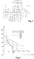
- the figure 1 is a block diagram of a hybrid powertrain (GMP) 1, three shafts and two electric machines, using three dog clutch systems, the operation of which is illustrated by the cited publication.
- the GMP 1 has three actuators (heat engine 2, main electrical machine 3 (ME), secondary electrical machine 4 (HSG)), a solid primary shaft 5 connected to the heat engine, a hollow primary shaft 6 connected to the main electrical machine 3 , a secondary shaft 7, and a countershaft 8 connected to the secondary electrical machine 4.
- the gears are engaged by three clutch couplers C1, C2, C3, devoid of mechanical synchronizers:
- the gearbox combines the torque of the heat engine 1 of the main electric machine 3, and of the secondary electrical machine 4 on the common output shaft 7, in the direction of the vehicle wheels.
- the gear changes are carried out under the control of the three dog clutch couplers C1, C2, C3, arranged respectively on the solid primary shaft 5, on the secondary shaft 6 and on the transfer shaft 8.
- the first coupler said primary coupler C1, placed on the solid primary shaft 5, makes it possible to engage a long thermal ICE4 ratio on the right, and to couple the two primary shafts on the left.
- the second coupler called secondary coupler C2, placed on the secondary shaft, enables two electrical reports EV1 and EV2 to be engaged.
- the gearbox has two so-called electric reports for the movement from the main electric machine ME, and four so-called thermal reports for the movement from the entire secondary electric machine (HSG) and the heat engine (ICE) if he is present. Their combination allows the box to have 15 speeds. Each speed transmits a maximum force to the wheel according to the speed of movement of the vehicle. By way of example, the figure 2 passing curves for some of them.
- the speed of movement of the vehicle V is expressed in kilometers per hour.
- the maximum wheel force F as a function of the speed is expressed in Newtons (N), for the two electric speeds (ZE1 and ZE2), and four hybrid speeds, called respectively Hyb21, Hyb22, Hyb32, Hyb42.
- N Newtons
- the first number indicates the thermal ratio of the gearbox.
- the second indicates its electrical report.
- the values taken into account to calculate the min / max mechanical power limitations of electrical machines are advantageously an image of the limitations imposed by the battery as a function of its “ long-term ” energy potential, and of the how to use of each machine.
- a first measure to improve the quality of the passages consists in derogating from the limitations based on the “ long-term ” state (approximately 20s) of the battery, to switch momentarily to a shorter-term forecast (approximately 2 seconds).
- the gearbox controller takes control of its actuators to change gear, the battery power potential is positioned on “ short-term ” limits, which are less restrictive than the previous ones. This takes advantage of the performance of the system, to improve the quality of the passage, and to achieve the transition as quickly as possible.
- a change from speed “Hyb22” to “Hyb21”, consists in changing the electric gear in hybrid mode, while remaining on the second thermal gear.
- the secondary electrical machine (HSG) ensures with the heat engine the achievement of the torque requested from the wheel.
- the main electrical machine (ME) performs the transition, that is to say its synchronization on the speed of the new ratio between the declutching of one pinion and the clutch of another pinion.
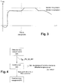
- the secondary HSG machine can be saturated, even on “short term ” battery limitations. This phenomenon is illustrated by the figure 3 , where the compensation torque supplied by the secondary machine C HSG is saturated by the " short term " limitation, after the WP6 gearbox computer has been checked.
- the invention seeks to optimize the power potential supplied by the battery, and the calculation of the saturation torques (minimum and maximum) of electric machines during gear changes.
- the proposed method is based on an anticipation of the switch from “ long-term ” limitations to “short-term ” limitations imposed by the forecast state of the battery.
- This method introduces a new process for developing a torque setpoint for the electrical machines of a vehicle powertrain, comprising at least one controlled dog clutch, a main electrical machine capable of transmitting torque to the wheels of the vehicle on two separate gear ratios, and a secondary electric machine capable of providing compensating torque to the wheel during main machine gear changes.
- the maximum and minimum torques imposed on the electric machines in established ratio are calculated according to a forward forecast state of a common supply battery (“ short-term limitation ” and “long-term limitation ”) . But it is planned to calculate in addition, new values of effective min / max torque of electric machines, which make the gear change smoother, reducing the acceleration hole of the gear change, while respecting the constraints drums.
- a new limitation of the torques of the two electric machines is imposed in advance, stricter than that of the established ratio, in order to ensure without discontinuity during the gear change, the synchronization of the main machine (ME) on the new gear, and the torque compensation by the secondary machine (HSG).
- a new method of calculating the min / max saturations of the effective torque of the two electric machines ME and HSG used during a gear change is proposed. It makes it possible to absorb excessively high jumps in the torque setpoint, and to improve the distribution of battery power between the two electric machines.
- the power level required during the transition is provided before the start of the shift, and more precisely before the WP6 gearbox controller takes over the actuators.
- the forecast is made by calculating an anticipated speed deviation on which the power level necessary for the synchronization phase is positioned.
- the limitations which are imposed by the battery (calculated in steady state by the main computer of the GMP " Powertrain Torque Management" (WP2), and sent to the gearbox controller (WP6), have thanks to the invention a smoother evolution, allowing to avoid the various instantaneous changes of the effective torque.
- the GMP shift laws calculator (WP4) is responsible for the state setpoint of the kinematic chain. It imposes on the WP6 gearbox computer an early change of ratio request “anticipated driveline state setpoint ”, Vsx_dls_tgt_ant ”, by interpretation of the driver's wishes. From the setpoint Vsx_dls_tgt_ant ”, WP6 calculates an anticipated speed differential ⁇ _anticipated. On the basis of this, it establishes the torque limitation guidelines for electric machines. These instructions are sent to the “Powertrain torque management” (WP2) GMP torque calculator, to which they apply before the start of the shift.
- WP2 Powertrain torque management
- the anticipated speed differential ⁇ _ anticipated calculated from the setpoint Vsx_dls_tgt_ant , remains constant during the passage: it varies only with the speed of the vehicle, which itself evolves very slowly over a horizon of 2 seconds in the example considered. .
- the gearbox calculator calculates the min / max limitations of effective torques of the two machines HSG and ME Vxx_min / max_esnd_ecrk-tqe_limit, making it possible to carry out the anticipated change of gear if this is confirmed, while ensuring torque compensation at the wheel at the correct level of approval.
- WP2 Powertrain torque management
- the gearbox calculation unit limits the torques of the electric machines in advance, before the start of the synchronization carried out under its control. When the change of gear is confirmed, there is no discontinuity in the torque limitations, because the level of electric power required by the limited torques remains lower than the maximum and minimum torques imposed on the two electric machines in established gear.
- the invention makes it possible to optimize the power potential supplied by the battery, and the calculation of the min / max saturations of the electric machines from the long and short term power limitations imposed by the battery. It is based on the taking into account by the gearbox controller of the battery power limitations and the saturation of the electrical machines. As a result, it is easy to implement, and does not introduce any additional cost.
Landscapes
- Engineering & Computer Science (AREA)
- Mechanical Engineering (AREA)
- Transportation (AREA)
- Chemical & Material Sciences (AREA)
- Combustion & Propulsion (AREA)
- Automation & Control Theory (AREA)
- General Engineering & Computer Science (AREA)
- Human Computer Interaction (AREA)
- Control Of Transmission Device (AREA)
- Hybrid Electric Vehicles (AREA)
- Electric Propulsion And Braking For Vehicles (AREA)
Description
- L'invention concerne le contrôle des transmissions automatiques de groupe motopropulseur (GMP) de véhicule, électrique ou hybride, comportant une boîte de vitesses qui regroupe le couple de plusieurs actionneurs (moteurs thermiques et machines électriques) en direction des roues du véhicule, sur différents rapports de transmission, par l'intermédiaire d'un différentiel.
- Plus précisément, elle a pour objet un procédé d'élaboration d'une consigne de couple aux machines électriques d'un groupe motopropulseur de véhicule, comportant au moins une boîte de vitesses à crabots pilotés, une machine électrique principale pouvant transmettre du couple aux roues du véhicule sur deux rapports de boîte distincts, et une machine électrique secondaire capable fournir un couple de compensation à la roue pendant les changements de rapport de la machine principale. Dans ce procédé, les couples maximum et minimum imposés aux deux machines électriques en rapport établi, sont calculés en fonction d'un état prévisionnel à terme, d'une batterie d'alimentation commune.
- L'invention a également pour objet un groupe motopropulseur électrique de véhicule, comportant au moins une boîte de vitesses à crabots pilotés, une machine électrique principale (ME) pouvant transmettre du couple aux roues du véhicule sur deux rapports de boîte distincts, et une machine électrique secondaire (HSG).
- Elle a également pour objet un groupe motopropulseur hybride de véhicule, comportant au moins une boîte de vitesses à crabots pilotés, un moteur thermique, une machine électrique principale (ME) pouvant transmettre du couple aux roues du véhicule sur deux rapports de boîte distincts, et une machine électrique secondaire (HSG), capable fournir un couple de compensation à la roue pendant les changements de rapport de la machine principale.
- L'invention s'applique en particulier aux groupes motopropulseurs (GMP) de ce type, dans lesquels l'engagement et le désengagement des rapports est assuré par des systèmes de couplage pilotés sans synchroniseur, à crabots ou dents plates, appelés aussi « clabots », mobiles axialement sur un arbre. Les crabots sont pilotés par l'intermédiaire de fourchettes de commande en direction de pignons de vitesses fixes axialement, tournant fou sur leur arbre. L'engagement des crabots mobiles sur les pignons, met en prise l'arbre et le pignon, pour transmettre le couple aux roues sur le rapport de transmission engagé.
- La publication
FR 3 007 696 - Les deux machines électriques (ME) et (HSG) sont alimentées par la même batterie, qui fournit la quantité d'énergie nécessaire au fonctionnement du GMP. Cette quantité dépend du fonctionnement de chaque machine (motrice ou génératrice), et du niveau de puissance qui est demandé à la batterie par chacune d'elles. Ce niveau dépend de la demande de puissance à la roue, et de la répartition du couple entre les machines électriques et le moteur thermique. La puissance électrique fournie par la batterie est limitée par sa tension minimum, par sa température, et par son niveau de charge (SOC pour « State Of Charge » en anglais). La puissance électrique disponible dans la batterie détermine l'apport potentiel maximum en couple de celle-ci dans chaque situation. Cet apport est limité entre un couple maximum et un couple minimum, pour chaque machine électrique. Il prend en compte son mode d'utilisation (motrice ou génératrice).
- Dans le but d'augmenter la durée de vie de la batterie, et de l'exploiter le plus longtemps possible, les limitations des couples effectifs min/max des machines électriques sont généralement calculées « à long terme », par exemple sur des prévisions à au moins 20 secondes. Les valeurs prises en compte pour calculer les limitations min/max de puissance mécanique (et de couple) des machines électriques, imposées par la batterie sont calculées en fonction de son potentiel d'énergie à long terme, et du mode d'utilisation de chaque machine.
- Pendant les changements de rapport, plusieurs phénomènes peuvent se produire et être perçus désagréablement par les utilisateurs, comme des trous d'accélération, des chocs ou à-coups, des ralentissements, des effets de « salut », etc.
- Les limitations de couple min/max imposées aux machines électriques permettent dans une certaine mesure de pallier ces phénomènes. En effet, un trou d'accélération est généralement lié au fonctionnement d'une machine électrique en sous-performance. C'est le cas pour une machine qui est pilotée sur son couple maximum, si la puissance qui lui est allouée par la batterie est insuffisante pour assurer l'accélération demandée par le conducteur, notamment si cette puissance est limitée en fonction d'une prévision à trop long terme de l'état de la batterie.
- Par la publication
FR 2 954 153 - La présente invention vise à améliorer la qualité des changements de vitesse, perçue par les utilisateurs du véhicule.
- Dans ce but, elle prévoit que, en anticipation d'un changement de rapport de la machine principale, on impose par avance une nouvelle limitation des couples minimum et maximum des deux machines électriques plus stricte que celle du rapport établi afin d'assurer sans discontinuité pendant le changement de rapport la synchronisation de la machine principale sur le nouveau rapport et la compensation du couple par la machine secondaire, les limitations des consignes de couple des machines électriques étant calculées en fonction d'un différentiel de régime anticipé basé sur la variation de régime à effectuer par la machine principale pour se synchroniser sur le nouveau rapport.
- Suivant une forme particulière de l'invention, l'anticipation du changement de rapport est déterminée à partir d'une interprétation de la volonté du conducteur.
- D'autres caractéristiques et avantages de l'invention, ressortiront clairement à la lecture de la description suivante d'un mode de réalisation non limitatif de celle-ci, en se reportant aux dessins annexés, sur lesquels :
- la
figure 1 est un exemple d'architecture GMP hybride simplifié - la
figure 2 , regroupe ses courbes de passage de vitesses, - la
figure 3 , illustre les contraintes de limitation de couple, habituelles lors des passages de vitesses, - la
figure 4 résume la stratégie, et - la
figure 5 illustre les évolutions du couple et de la puissance pendant le passage. - La
figure 1 est un schéma fonctionnel de groupe motopropulseur (GMP) hybride 1, à trois arbres et deux machines électriques, utilisant trois systèmes de couplage à crabots, dont le fonctionnement est illustré par la publication citée. Le GMP 1 comporte trois actionneurs (moteur thermique 2, machine électrique principale 3 (ME), machine électrique secondaire 4 (HSG)), un arbre primaire plein 5 relié au moteur thermique, un arbre primaire creux 6 relié à la machine électrique principale 3, un arbre secondaire 7, et un arbre de renvoi 8 relié à la machine électrique secondaire 4. Les rapports sont enclenchés par trois coupleurs à crabots C1, C2, C3, dépourvus de synchroniseurs mécaniques :
La boîte de vitesses regroupe le couple du moteur thermique 1 de la machine électrique principale 3, et de la machine électrique secondaire 4 sur l'arbre de sortie commun 7, en direction des roues du véhicule. Les changements de rapport s'effectuent sous le contrôle des trois coupleurs à crabots C1, C2, C3, disposés respectivement sur l'arbre primaire plein 5, sur l'arbre secondaire 6 et sur l'arbre de transfert 8. Le premier coupleur, dit coupleur primaire C1, placé sur l'arbre primaire plein 5, permet d'enclencher un rapport thermique ICE4 long à droite, et de coupler les deux arbres primaires à gauche. Le deuxième coupleur, dit coupleur secondaire C2, placé sur l'arbre secondaire, permet d'enclencher deux rapports électriques EV1 et EV2. Le troisième coupleur, dit coupleur de transfert C3, placé sur l'arbre de renvoi 8, permet de transférer le couple de la machine électrique secondaire sur l'arbre secondaire 7 (à droite), ou sur l'arbre primaire creux 6 (à gauche). - La boîte présente deux rapports, dits électriques, pour le mouvement issu de la machine électrique principale ME, et quatre rapports, dits thermiques, pour le mouvement issu de l'ensemble de la machine électrique secondaire (HSG) et du moteur thermique (ICE) s'il est présent. Leur combinaison permet à la boîte de disposer de 15 vitesses. Chaque vitesse transmet une force maximum à la roue en, fonction de la vitesse de déplacement du véhicule. A titre d'exemple, on a représenté sur la
figure 2 les courbes de passage pour certains d'entre eux. La vitesse de déplacement du véhicule V est exprimée en kilomètres/heure. La force aux roues maximale F en fonction de la vitesse, est exprimée en Newton (N), pour les deux vitesses électriques (ZE1 et ZE2), et quatre vitesses hybrides, appelés respectivement Hyb21, Hyb22, Hyb32, Hyb42. Le premier chiffre indique le rapport thermique de la boîte de vitesses. Le deuxième indique son rapport électrique. - Comme indiqué plus haut, les valeurs prises en compte pour calculer les limitations min/max de puissance mécanique des machines électriques, sont avantageusement une image des limitations imposées par la batterie en fonction de son potentiel d'énergie à « long terme », et du mode d'utilisation de chaque machine. Une première mesure pour améliorer la qualité des passages, consiste à déroger aux limitations basées sur l'état « à long terme » (environ 20s) de la batterie, pour basculer momentanément sur une prévision à plus court terme (environ 2 secondes). Lorsque le contrôleur de la boîte prend le contrôle de ses actionneurs pour réaliser un passage de vitesses, le potentiel de puissance de la batterie se positionne sur les limitations « court terme », moins contraignantes que les précédentes. On profite ainsi des performances du système, pour améliorer la qualité de passage, et réaliser la transition le plus rapidement possible.
- Toutefois, si le changement de limitation s'effectue au moment où le contrôleur de la boîte de vitesses prend le contrôle du GMP pour réaliser le passage, il peut provoquer des sauts de couple en réponse au changement brusque de la consigne de couple appliquée sur les machines électriques, en particulier sur celle qui doit assurer la compensation de couple pendant la mise au neutre d'un coupleur. De tels sauts de couple, se traduisent par des chocs qui nuisent à l'agrément de conduite du véhicule, en dépit de l'objectif recherché.
- Dans l'exemple illustré par les
figures 1 et 2 , un passage de la vitesse « Hyb22 » à « Hyb21 », consiste à changer de rapport électrique en mode hybride, en restant sur le deuxième rapport thermique. Pendant le changement, la machine électrique secondaire (HSG) assure avec le moteur thermique la réalisation du couple demandé à la roue. La machine électrique principale(ME) réalise la transition, c'est-à-dire sa synchronisation sur le régime du nouveau rapport entre le dé-crabotage d'un pignon et le crabotage d'un autre pignon. En fonction de la puissance demandée à la roue, la machine secondaire HSG peut être saturée, même sur les limitations « court terme » de la batterie. Ce phénomène est illustré par lafigure 3 , où le couple de compensation fourni par la machine secondaire CHSG est saturé par la limitation « court terme », après la prise de contrôle du calculateur de la boîte WP6. - Si la machine principale (ME), qui est en phase de synchronisation de régime, ne dispose pas de puissance suffisante, cette phase est allongée. A l'inverse, une diminution du couple de compensation visant à raccourcir la phase de synchronisation, augmente le choc ressenti par les usagers.
- L'invention cherche à optimiser le potentiel de puissance fourni par la batterie, et le calcul des couples de saturation (minimum et maximum) des machines électriques pendant les changements de vitesse.
- La méthode proposée repose sur une anticipation du basculement des limitations « long terme » vers les limitations « court terme » imposées par l'état prévisionnel de la batterie. Cette méthode introduit un nouveau procédé d'élaboration d'une consigne de couple aux machines électriques d'un groupe motopropulseur de véhicule, comportant au moins une boîte de vitesses à crabots pilotés, une machine électrique principale pouvant transmettre du couple aux roues du véhicule sur deux rapports de boîte distincts, et une machine électrique secondaire capable fournir un couple de compensation à la roue pendant les changements de rapport de la machine principale.
- Dans le nouveau procédé, les couples maximum et minimum imposés aux machines électriques en rapport établi, sont calculés en fonction d'un état prévisionnel à terme d'une batterie d'alimentation commune (« limitation court terme » et « limitation long terme »). Mais il est prévu de calculer en plus, des nouvelles valeurs de couple effectif min/max des machines électriques, qui permettent de rendre le passage de rapport plus lisse, en réduisant le trou d'accélération du changement de rapport, tout en respectant les contraintes de la batterie.
- Conformément à l'invention, en anticipation d'un changement de rapport de la machine principale (ME), on impose par avance une nouvelle limitation des couples des deux machines électriques, plus stricte que celle du rapport établi, afin d'assurer sans discontinuité pendant le changement de rapport, la synchronisation de la machine principale (ME) sur le nouveau rapport, et la compensation du couple par la machine secondaire (HSG) .
- Un nouveau mode de calcul des saturations min/max du couple effectif des deux machines électriques ME et HSG utilisées lors d'un changement de rapport, est proposé. Il permet de résorber les sauts trop élevés de consigne de couple, et d'améliorer la répartition de la puissance de la batterie entre les deux machines électriques.
- Conformément à l'invention, le niveau de puissance requis au cours de la transition, est prévu avant le début du passage, et plus précisément avant la prise de contrôle du contrôleur de boîte WP6 sur les actionneurs. La prévision s'effectue par le calcul d'un écart de régime anticipé sur lequel on positionne le niveau de puissance nécessaire pour la phase de synchronisation. Les limitations qui sont imposées par la batterie (calculées en régime établi par le calculateur principal du GMP « Powertrain Torque Management » (WP2), et envoyées au contrôleur de boîte (WP6), ont grâce à l'invention une évolution plus lisse, permettant d'éviter les différents changements instantanés du couple effectif.
- L'anticipation du changement de rapport, est déterminée à partir d'une interprétation de la volonté du conducteur. Comme indiqué sur la
figure 4 , le calculateur de lois de passage du GMP (WP4) est responsable de la consigne d'état de la chaîne cinématique. Il impose au calculateur de boîte WP6 une demande de changement de rapport anticipée « consigne de driveline state anticipée », Vsx_dls_tgt_ant », par interprétation de la volonté du conducteur. A partir de la consigne Vsx_dls_tgt_ant », WP6 calcule un différentiel de régime anticipé Δω_anticipé. Sur la base de celui-ci, il établit les consignes de limitation de couple des machines électriques. Ces consignes sont envoyées au calculateur de couple du GMP « Powertrain torque management » (WP2), auquel elles s'imposent avant le début du passage. - Dans l'exemple cité plus haut, d'un passage de la vitesse Hyb22 à Hyb21, on cherche à synchroniser la machine électrique principale (ME) d'un régime X correspondant au rapport EV2, à un régime Y correspondant au rapport EV1. La consigne Vsx_dls_tgt_ant est équivalente au mode cinématique Hyb21. Le calcul du différentiel de régime anticipé, se base sur la variation de régime à réaliser pour pouvoir actionner le rapport anticipé :

- En fonction de Δω_anticipé, le calculateur de boîte (WP6) calcule les limitations min/max de couples effectifs des deux machines HSG et ME Vxx_min/max_esnd_ecrk-tqe_limit, permettant de réaliser le changement de rapport anticipé si celui-ci est confirmé, tout en assurant une compensation du couple à la roue au bon niveau d'agrément. Ces limitations sont prises en compte par le calculateur de couple du GMP « Powertrain torque management » (WP2) qui les impose aux machines électriques.
- L'unité de calcul de la boîte de vitesses (WP6) limite par avance les couples des machines électriques, avant le début de la synchronisation effectuée sous son contrôle. Lorsque le changement de rapport est confirmé, il n'y a pas de discontinuité dans les limitations de couple, car le niveau de puissance électrique requis par les couples limités reste inférieur aux couples maximum et minimum imposés aux deux machines électriques en rapport établi.
- La
figure 5 illustre le déroulement des calculs effectués dans l'architecture logicielle du contrôleur de la boîte de vitesses WP6. Les dates indiquées en abscisse sur les deux graphes sont respectivement : - t1 : élaboration de la consigne de changement de rapport par le calculateur du GMP (WP4),
- t2 : anticipation de la prise de main du contrôleur de boîte WP6,
- t3 : prise de main réelle par le contrôleur de boîte
- t4 : début de la synchronisation,
- t5 : début de la reprise de contrôle par le calculateur GMP,
- t6 : fin de cette reprise de contrôle.
- Sur le graphe puissance, on a représenté le niveau de « limitation long terme » s'imposant avant t1, et après t6. Le niveau de limitation court terme, supérieur à celui-ci, est également indiqué. Le différentiel de régime anticipé Δω_anticipé, calculé à partir de t1, est appliqué de t2 à t4. Il détermine une « nouvelle limitation de puissance », qui se substitue entre t2 et t6, à la puissance de « limitation long terme » imposée par la batterie. La synchronisation, opérée entre t4 et t5, fait disparaître le différentiel de régime.
- Le pic de couple imposé par le changement instantané des consignes de couple effectif entre t2 et t4 disparaît. La diminution de couple de la machine effectuant la compensation est évitée. On effectue une bonne répartition de la puissance disponible de la batterie, entre les deux machines électriques.
- En conclusion, l'invention permet d'optimiser le potentiel de puissance fourni par la batterie, et le calcul des saturations min/max des machines électriques à partir des limitations de puissance long et court terme, imposées par la batterie. Elle s'appuie sur la prise en compte par le contrôleur de boîte de vitesses, des limitations de puissance de la batterie et des saturations des machines électriques. De ce fait, elle est facile à mettre en œuvre, et n'introduit aucun coût supplémentaire.
Claims (8)
- Procédé d'élaboration d'une consigne de couple aux machines électriques (ME, HSG) d'un groupe motopropulseur (GMP) de véhicule, comportant au moins une boîte de vitesses à crabots pilotés, une machine électrique principale (ME) pouvant transmettre du couple aux roues du véhicule sur deux rapports de boîte distincts, et une machine électrique secondaire (HSG) capable fournir un couple de compensation à la roue pendant les changements de rapport de la machine principale, dans lequel les couples maximum et minimum imposés aux deux machines électriques en rapport établi sont calculés en fonction d'un état prévisionnel à terme d'une batterie d'alimentation commune, caractérisé en ce que, en anticipation d'un changement de rapport de la machine principale (ME), on impose par avance une nouvelle limitation des couples minimum et maximum des deux machines électriques plus stricte que celle du rapport établi afin d'assurer sans discontinuité pendant le changement de rapport la synchronisation de la machine principale (ME) sur le nouveau rapport et la compensation du couple par la machine secondaire (HSG), les limitations des consignes de couple des machines électriques étant calculées en fonction d'un différentiel de régime anticipé basé sur la variation de régime à effectuer par la machine principale pour se synchroniser sur le nouveau rapport.
- Procédé d'élaboration d'une consigne de couple selon la revendication 1, caractérisé en ce que l'anticipation du changement de rapport est déterminée à partir d'une interprétation de la volonté du conducteur.
- Procédé d'élaboration d'une consigne de couple selon la revendication 1 ou 2, caractérisé en ce que l'unité de calcul du GMP (WP4) interprétant la volonté du conducteur, envoie une demande de changement de rapport anticipée à l'unité de calcul de la boîte de vitesses (WP6).
- Procédé d'élaboration d'une consigne de couple selon la revendication 3, caractérisé en ce que l'unité de calcul de la boîte de vitesses (WP6) limite par avance les couples des machines électriques, avant le début de la synchronisation.
- Procédé d'élaboration d'une consigne de couple selon la revendication 4, caractérisé en ce que les couples limités requièrent un niveau de puissance électrique qui reste inférieur à celui qui est requis par les couples maximum et minimum imposés aux deux machines électriques en rapport établi.
- Procédé d'élaboration d'une consigne de couple selon la revendication 4 ou 5, caractérisé en ce que les couples limités sont calculés par l'unité de calcul de la boîte de vitesses (WP6) avant qu'elle prenne le contrôle sur les machines électriques.
- Groupe motopropulseur (GMP) électrique de véhicule, comportant au moins une boîte de vitesses à crabots pilotés, une machine électrique principale (ME) pouvant transmettre du couple aux roues du véhicule sur deux rapports de boîte distincts, et une machine électrique secondaire (HSG) capable fournir un couple de compensation à la roue pendant les changements de rapport de la machine principale, caractérisé en ce que en anticipation d'un changement de rapport de la machine principale (ME), on élabore une consigne de couple aux machines électriques (ME, HSG) conformément à l'une des revendications 1 à 6.
- Groupe motopropulseur (GMP) hybride de véhicule, comportant au moins une boîte de vitesses à crabots pilotés, un moteur thermique, une machine électrique principale (ME) pouvant transmettre du couple aux roues du véhicule sur deux rapports de boîte distincts, et une machine électrique secondaire (HSG) capable fournir un couple de compensation à la roue pendant les changements de rapport de la machine principale, caractérisé en ce que en anticipation d'un changement de rapport de la machine principale (ME), on élabore une consigne de couple aux machines électriques (ME, HSG) conformément à l'une des revendications 1 à 6.
Applications Claiming Priority (2)
| Application Number | Priority Date | Filing Date | Title |
|---|---|---|---|
| FR1755192A FR3067314B1 (fr) | 2017-06-09 | 2017-06-09 | Procede d'elaboration d'une consigne de couple aux machines electriques d'un groupe motopropulseur de vehicule et groupe motopropulseur de vehicule |
| PCT/FR2018/050913 WO2018224742A1 (fr) | 2017-06-09 | 2018-04-11 | Procede d'elaboration d'une consigne de couple aux machines electriques d'un groupe motopropulseur de vehicule et groupe motopropulseur de vehicule |
Publications (2)
| Publication Number | Publication Date |
|---|---|
| EP3634797A1 EP3634797A1 (fr) | 2020-04-15 |
| EP3634797B1 true EP3634797B1 (fr) | 2021-08-11 |
Family
ID=59649890
Family Applications (1)
| Application Number | Title | Priority Date | Filing Date |
|---|---|---|---|
| EP18719966.6A Active EP3634797B1 (fr) | 2017-06-09 | 2018-04-11 | Procédé d'élaboration d'une consigne de couple aux machines électriques d'un groupe motopropulseur de véhicule et groupe motopropulseur de véhicule |
Country Status (6)
| Country | Link |
|---|---|
| EP (1) | EP3634797B1 (fr) |
| JP (1) | JP2020522973A (fr) |
| KR (1) | KR102657972B1 (fr) |
| CN (1) | CN110770059B (fr) |
| FR (1) | FR3067314B1 (fr) |
| WO (1) | WO2018224742A1 (fr) |
Families Citing this family (10)
| Publication number | Priority date | Publication date | Assignee | Title |
|---|---|---|---|---|
| DE102019203486A1 (de) * | 2019-03-14 | 2020-09-17 | Zf Friedrichshafen Ag | Hybrid-Getriebeeinrichtung sowie Kraftfahrzeug |
| US11040607B2 (en) | 2019-07-12 | 2021-06-22 | Allison Transmission, Inc. | Multiple motor multiple speed continuous power transmission |
| US11331991B2 (en) | 2019-12-20 | 2022-05-17 | Allison Transmission, Inc. | Motor configurations for multiple motor mixed-speed continuous power transmission |
| US11173781B2 (en) | 2019-12-20 | 2021-11-16 | Allison Transmission, Inc. | Component alignment for a multiple motor mixed-speed continuous power transmission |
| US11371589B2 (en) | 2020-04-30 | 2022-06-28 | Allison Transmission, Inc. | Clutch configurations for a multiple motor mixed-speed continuous power transmission |
| FR3110527B1 (fr) | 2020-05-19 | 2022-06-10 | Renault Sas | Procédé de commande d’un groupe motopropulseur pour véhicule automobile à transmission électrique hybride |
| US11193562B1 (en) | 2020-06-01 | 2021-12-07 | Allison Transmission, Inc. | Sandwiched gear train arrangement for multiple electric motor mixed-speed continuous power transmission |
| US11421759B2 (en) | 2020-06-02 | 2022-08-23 | Allison Transmission, Inc. | Output gearing for a dual motor mixed-speed continuous power transmission |
| EP4249311A1 (fr) | 2022-03-25 | 2023-09-27 | Volvo Truck Corporation | Procédé d'attribution de puissance entre des machines électriques dans une transmission d'un véhicule électrique |
| FR3156409A1 (fr) * | 2023-12-07 | 2025-06-13 | AMPERE s.a.s | Procédé et dispositif de gestion du fonctionnement d’une boite de vitesses à crabots d’un véhicule automobile hybride |
Family Cites Families (9)
| Publication number | Priority date | Publication date | Assignee | Title |
|---|---|---|---|---|
| FR2799163B1 (fr) * | 1999-10-01 | 2002-11-15 | Renault | Procede de commande d'un vehicule hybride |
| JP2002089687A (ja) * | 2000-09-18 | 2002-03-27 | Aisin Aw Co Ltd | ハイブリッド車輌の制御装置 |
| JP3852402B2 (ja) * | 2002-12-25 | 2006-11-29 | トヨタ自動車株式会社 | ハイブリッド駆動装置の制御装置 |
| JP2005186740A (ja) * | 2003-12-25 | 2005-07-14 | Aisin Seiki Co Ltd | 車両の変速制御装置 |
| CN102224048A (zh) * | 2008-11-20 | 2011-10-19 | 丰田自动车株式会社 | 车辆用动力传递装置的控制装置 |
| FR2954253B1 (fr) * | 2009-12-17 | 2012-07-13 | Peugeot Citroen Automobiles Sa | Procede et dispositif pour compenser une valeur perdue de couple de traction de vehicule |
| CN102849062B (zh) * | 2012-09-18 | 2015-10-14 | 中国第一汽车股份有限公司 | 一种增程式电动汽车的驱动控制方法 |
| FR3007696B1 (fr) * | 2013-06-26 | 2015-06-26 | Renault Sa | Transmission hybride avec une machine electrique additionnelle et procede de commande |
| US9056613B2 (en) * | 2013-11-06 | 2015-06-16 | Ford Global Technologies, Llc | System and method for upshift torque modification using an upstream clutch in a hybrid vehicle |
-
2017
- 2017-06-09 FR FR1755192A patent/FR3067314B1/fr not_active Expired - Fee Related
-
2018
- 2018-04-11 EP EP18719966.6A patent/EP3634797B1/fr active Active
- 2018-04-11 JP JP2019567581A patent/JP2020522973A/ja not_active Ceased
- 2018-04-11 WO PCT/FR2018/050913 patent/WO2018224742A1/fr not_active Ceased
- 2018-04-11 CN CN201880039049.4A patent/CN110770059B/zh active Active
- 2018-04-11 KR KR1020197037187A patent/KR102657972B1/ko active Active
Also Published As
| Publication number | Publication date |
|---|---|
| KR102657972B1 (ko) | 2024-04-17 |
| JP2020522973A (ja) | 2020-07-30 |
| CN110770059B (zh) | 2023-06-23 |
| FR3067314A1 (fr) | 2018-12-14 |
| BR112019025825A2 (pt) | 2020-07-07 |
| KR20200016866A (ko) | 2020-02-17 |
| CN110770059A (zh) | 2020-02-07 |
| EP3634797A1 (fr) | 2020-04-15 |
| WO2018224742A1 (fr) | 2018-12-13 |
| FR3067314B1 (fr) | 2019-06-21 |
Similar Documents
| Publication | Publication Date | Title |
|---|---|---|
| EP3634797B1 (fr) | Procédé d'élaboration d'une consigne de couple aux machines électriques d'un groupe motopropulseur de véhicule et groupe motopropulseur de véhicule | |
| EP3793852B1 (fr) | Transmission hybride a machine électrique deportée | |
| EP3710732B1 (fr) | Procédé et système de commande d'une transmission automatique sans embrayage pour véhicule automobile à propulsion hybride | |
| CN105246752A (zh) | 混合动力车辆用驱动装置的变速控制装置 | |
| EP3694736B1 (fr) | Procédé de pilotage d'un groupe motopropulseur hybride électrique | |
| WO2013072609A1 (fr) | Groupe motopropulseur pour vehicule electrique de competition et procede de commande | |
| US20100262324A1 (en) | Vehicular power transmission control apparatus | |
| EP3691922B1 (fr) | Procédé de pilotage d'un groupe motopropulseur de véhicule automobile | |
| EP2098755B1 (fr) | Procédé de passage descendant avec couple moteur positif, pour boîte de vitesses à crabots | |
| JP2010241330A (ja) | 車両の動力伝達制御装置 | |
| EP3580103B1 (fr) | Procédé d'élaboration de la consigne de couple aux actionneurs d'un groupe motopropulseur hybride | |
| EP3589510A1 (fr) | Dispositif de contrôle des couplages/découplages d'une machine motrice d'un véhicule lors d'un changement de rapport | |
| EP3516270B1 (fr) | Procede de synchronisation d'un pignon fou sur un arbre de boite de vitesses | |
| FR3101305A1 (fr) | Procede de selection de la consigne d’etat d’une chaine cinematique de vehicule | |
| SE1550551A1 (sv) | A method for shifting to a reverse gear in a hybrid vehicle,a hybrid vehicle, a computer program for shifting to a reve rse gear and a computer program product comprising program code. | |
| FR3094052A1 (fr) | Procédé et dispositif de contrôle du placement dans l’état de glissement d’un embrayage d’un véhicule à boîte de vitesses robotisée | |
| EP2098752B1 (fr) | Procédé de passage montant avec couple moteur positif, pour boîte de vitesses à crabots | |
| EP2098754B1 (fr) | Procédé de passage descendant avec couple moteur négatif, pour boîte de vitesses à crabots | |
| JP2017115929A (ja) | 動力伝達装置の制御装置 | |
| FR3145726A1 (fr) | Procédé de commande d’une chaîne de propulsion d’un véhicule hybride | |
| JP2016156458A (ja) | 車両の後進制御システム、車両、及び、車両の後進制御方法 | |
| JP2017043314A (ja) | ハイブリッド車両用駆動装置 | |
| JP2014061846A (ja) | ハイブリッド車両の制御装置 | |
| FR2956085A1 (fr) | Procede de passage descendant pour boite de vitesses a crabots | |
| FR2921525A1 (fr) | Dispositif d'asservissement en couple d'une machine electrique d'une chaine de traction electrique d'un vehicule comportant un estimateur de couple parasite |
Legal Events
| Date | Code | Title | Description |
|---|---|---|---|
| STAA | Information on the status of an ep patent application or granted ep patent |
Free format text: STATUS: UNKNOWN |
|
| STAA | Information on the status of an ep patent application or granted ep patent |
Free format text: STATUS: THE INTERNATIONAL PUBLICATION HAS BEEN MADE |
|
| PUAI | Public reference made under article 153(3) epc to a published international application that has entered the european phase |
Free format text: ORIGINAL CODE: 0009012 |
|
| STAA | Information on the status of an ep patent application or granted ep patent |
Free format text: STATUS: REQUEST FOR EXAMINATION WAS MADE |
|
| 17P | Request for examination filed |
Effective date: 20191126 |
|
| AK | Designated contracting states |
Kind code of ref document: A1 Designated state(s): AL AT BE BG CH CY CZ DE DK EE ES FI FR GB GR HR HU IE IS IT LI LT LU LV MC MK MT NL NO PL PT RO RS SE SI SK SM TR |
|
| AX | Request for extension of the european patent |
Extension state: BA ME |
|
| DAV | Request for validation of the european patent (deleted) | ||
| DAX | Request for extension of the european patent (deleted) | ||
| STAA | Information on the status of an ep patent application or granted ep patent |
Free format text: STATUS: EXAMINATION IS IN PROGRESS |
|
| 17Q | First examination report despatched |
Effective date: 20201119 |
|
| GRAP | Despatch of communication of intention to grant a patent |
Free format text: ORIGINAL CODE: EPIDOSNIGR1 |
|
| STAA | Information on the status of an ep patent application or granted ep patent |
Free format text: STATUS: GRANT OF PATENT IS INTENDED |
|
| INTG | Intention to grant announced |
Effective date: 20210302 |
|
| GRAS | Grant fee paid |
Free format text: ORIGINAL CODE: EPIDOSNIGR3 |
|
| GRAA | (expected) grant |
Free format text: ORIGINAL CODE: 0009210 |
|
| STAA | Information on the status of an ep patent application or granted ep patent |
Free format text: STATUS: THE PATENT HAS BEEN GRANTED |
|
| AK | Designated contracting states |
Kind code of ref document: B1 Designated state(s): AL AT BE BG CH CY CZ DE DK EE ES FI FR GB GR HR HU IE IS IT LI LT LU LV MC MK MT NL NO PL PT RO RS SE SI SK SM TR |
|
| REG | Reference to a national code |
Ref country code: CH Ref legal event code: EP |
|
| REG | Reference to a national code |
Ref country code: DE Ref legal event code: R096 Ref document number: 602018021642 Country of ref document: DE |
|
| REG | Reference to a national code |
Ref country code: IE Ref legal event code: FG4D Free format text: LANGUAGE OF EP DOCUMENT: FRENCH Ref country code: AT Ref legal event code: REF Ref document number: 1419036 Country of ref document: AT Kind code of ref document: T Effective date: 20210915 |
|
| REG | Reference to a national code |
Ref country code: LT Ref legal event code: MG9D |
|
| REG | Reference to a national code |
Ref country code: NL Ref legal event code: MP Effective date: 20210811 |
|
| REG | Reference to a national code |
Ref country code: AT Ref legal event code: MK05 Ref document number: 1419036 Country of ref document: AT Kind code of ref document: T Effective date: 20210811 |
|
| PG25 | Lapsed in a contracting state [announced via postgrant information from national office to epo] |
Ref country code: LT Free format text: LAPSE BECAUSE OF FAILURE TO SUBMIT A TRANSLATION OF THE DESCRIPTION OR TO PAY THE FEE WITHIN THE PRESCRIBED TIME-LIMIT Effective date: 20210811 Ref country code: AT Free format text: LAPSE BECAUSE OF FAILURE TO SUBMIT A TRANSLATION OF THE DESCRIPTION OR TO PAY THE FEE WITHIN THE PRESCRIBED TIME-LIMIT Effective date: 20210811 Ref country code: BG Free format text: LAPSE BECAUSE OF FAILURE TO SUBMIT A TRANSLATION OF THE DESCRIPTION OR TO PAY THE FEE WITHIN THE PRESCRIBED TIME-LIMIT Effective date: 20211111 Ref country code: PT Free format text: LAPSE BECAUSE OF FAILURE TO SUBMIT A TRANSLATION OF THE DESCRIPTION OR TO PAY THE FEE WITHIN THE PRESCRIBED TIME-LIMIT Effective date: 20211213 Ref country code: NO Free format text: LAPSE BECAUSE OF FAILURE TO SUBMIT A TRANSLATION OF THE DESCRIPTION OR TO PAY THE FEE WITHIN THE PRESCRIBED TIME-LIMIT Effective date: 20211111 Ref country code: HR Free format text: LAPSE BECAUSE OF FAILURE TO SUBMIT A TRANSLATION OF THE DESCRIPTION OR TO PAY THE FEE WITHIN THE PRESCRIBED TIME-LIMIT Effective date: 20210811 Ref country code: ES Free format text: LAPSE BECAUSE OF FAILURE TO SUBMIT A TRANSLATION OF THE DESCRIPTION OR TO PAY THE FEE WITHIN THE PRESCRIBED TIME-LIMIT Effective date: 20210811 Ref country code: FI Free format text: LAPSE BECAUSE OF FAILURE TO SUBMIT A TRANSLATION OF THE DESCRIPTION OR TO PAY THE FEE WITHIN THE PRESCRIBED TIME-LIMIT Effective date: 20210811 Ref country code: SE Free format text: LAPSE BECAUSE OF FAILURE TO SUBMIT A TRANSLATION OF THE DESCRIPTION OR TO PAY THE FEE WITHIN THE PRESCRIBED TIME-LIMIT Effective date: 20210811 Ref country code: RS Free format text: LAPSE BECAUSE OF FAILURE TO SUBMIT A TRANSLATION OF THE DESCRIPTION OR TO PAY THE FEE WITHIN THE PRESCRIBED TIME-LIMIT Effective date: 20210811 |
|
| PG25 | Lapsed in a contracting state [announced via postgrant information from national office to epo] |
Ref country code: PL Free format text: LAPSE BECAUSE OF FAILURE TO SUBMIT A TRANSLATION OF THE DESCRIPTION OR TO PAY THE FEE WITHIN THE PRESCRIBED TIME-LIMIT Effective date: 20210811 Ref country code: LV Free format text: LAPSE BECAUSE OF FAILURE TO SUBMIT A TRANSLATION OF THE DESCRIPTION OR TO PAY THE FEE WITHIN THE PRESCRIBED TIME-LIMIT Effective date: 20210811 Ref country code: GR Free format text: LAPSE BECAUSE OF FAILURE TO SUBMIT A TRANSLATION OF THE DESCRIPTION OR TO PAY THE FEE WITHIN THE PRESCRIBED TIME-LIMIT Effective date: 20211112 |
|
| RAP4 | Party data changed (patent owner data changed or rights of a patent transferred) |
Owner name: NISSAN MOTOR CO., LTD. Owner name: RENAULT S.A.S |
|
| PG25 | Lapsed in a contracting state [announced via postgrant information from national office to epo] |
Ref country code: NL Free format text: LAPSE BECAUSE OF FAILURE TO SUBMIT A TRANSLATION OF THE DESCRIPTION OR TO PAY THE FEE WITHIN THE PRESCRIBED TIME-LIMIT Effective date: 20210811 |
|
| PG25 | Lapsed in a contracting state [announced via postgrant information from national office to epo] |
Ref country code: DK Free format text: LAPSE BECAUSE OF FAILURE TO SUBMIT A TRANSLATION OF THE DESCRIPTION OR TO PAY THE FEE WITHIN THE PRESCRIBED TIME-LIMIT Effective date: 20210811 |
|
| REG | Reference to a national code |
Ref country code: DE Ref legal event code: R097 Ref document number: 602018021642 Country of ref document: DE |
|
| PG25 | Lapsed in a contracting state [announced via postgrant information from national office to epo] |
Ref country code: SM Free format text: LAPSE BECAUSE OF FAILURE TO SUBMIT A TRANSLATION OF THE DESCRIPTION OR TO PAY THE FEE WITHIN THE PRESCRIBED TIME-LIMIT Effective date: 20210811 Ref country code: SK Free format text: LAPSE BECAUSE OF FAILURE TO SUBMIT A TRANSLATION OF THE DESCRIPTION OR TO PAY THE FEE WITHIN THE PRESCRIBED TIME-LIMIT Effective date: 20210811 Ref country code: RO Free format text: LAPSE BECAUSE OF FAILURE TO SUBMIT A TRANSLATION OF THE DESCRIPTION OR TO PAY THE FEE WITHIN THE PRESCRIBED TIME-LIMIT Effective date: 20210811 Ref country code: EE Free format text: LAPSE BECAUSE OF FAILURE TO SUBMIT A TRANSLATION OF THE DESCRIPTION OR TO PAY THE FEE WITHIN THE PRESCRIBED TIME-LIMIT Effective date: 20210811 Ref country code: CZ Free format text: LAPSE BECAUSE OF FAILURE TO SUBMIT A TRANSLATION OF THE DESCRIPTION OR TO PAY THE FEE WITHIN THE PRESCRIBED TIME-LIMIT Effective date: 20210811 Ref country code: AL Free format text: LAPSE BECAUSE OF FAILURE TO SUBMIT A TRANSLATION OF THE DESCRIPTION OR TO PAY THE FEE WITHIN THE PRESCRIBED TIME-LIMIT Effective date: 20210811 |
|
| PLBE | No opposition filed within time limit |
Free format text: ORIGINAL CODE: 0009261 |
|
| STAA | Information on the status of an ep patent application or granted ep patent |
Free format text: STATUS: NO OPPOSITION FILED WITHIN TIME LIMIT |
|
| 26N | No opposition filed |
Effective date: 20220512 |
|
| PG25 | Lapsed in a contracting state [announced via postgrant information from national office to epo] |
Ref country code: IT Free format text: LAPSE BECAUSE OF FAILURE TO SUBMIT A TRANSLATION OF THE DESCRIPTION OR TO PAY THE FEE WITHIN THE PRESCRIBED TIME-LIMIT Effective date: 20210811 |
|
| PG25 | Lapsed in a contracting state [announced via postgrant information from national office to epo] |
Ref country code: SI Free format text: LAPSE BECAUSE OF FAILURE TO SUBMIT A TRANSLATION OF THE DESCRIPTION OR TO PAY THE FEE WITHIN THE PRESCRIBED TIME-LIMIT Effective date: 20210811 |
|
| REG | Reference to a national code |
Ref country code: CH Ref legal event code: PL |
|
| REG | Reference to a national code |
Ref country code: BE Ref legal event code: MM Effective date: 20220430 |
|
| PG25 | Lapsed in a contracting state [announced via postgrant information from national office to epo] |
Ref country code: MC Free format text: LAPSE BECAUSE OF FAILURE TO SUBMIT A TRANSLATION OF THE DESCRIPTION OR TO PAY THE FEE WITHIN THE PRESCRIBED TIME-LIMIT Effective date: 20210811 Ref country code: LU Free format text: LAPSE BECAUSE OF NON-PAYMENT OF DUE FEES Effective date: 20220411 Ref country code: LI Free format text: LAPSE BECAUSE OF NON-PAYMENT OF DUE FEES Effective date: 20220430 Ref country code: CH Free format text: LAPSE BECAUSE OF NON-PAYMENT OF DUE FEES Effective date: 20220430 |
|
| PG25 | Lapsed in a contracting state [announced via postgrant information from national office to epo] |
Ref country code: BE Free format text: LAPSE BECAUSE OF NON-PAYMENT OF DUE FEES Effective date: 20220430 |
|
| PG25 | Lapsed in a contracting state [announced via postgrant information from national office to epo] |
Ref country code: IE Free format text: LAPSE BECAUSE OF NON-PAYMENT OF DUE FEES Effective date: 20220411 |
|
| PG25 | Lapsed in a contracting state [announced via postgrant information from national office to epo] |
Ref country code: MK Free format text: LAPSE BECAUSE OF FAILURE TO SUBMIT A TRANSLATION OF THE DESCRIPTION OR TO PAY THE FEE WITHIN THE PRESCRIBED TIME-LIMIT Effective date: 20210811 Ref country code: CY Free format text: LAPSE BECAUSE OF FAILURE TO SUBMIT A TRANSLATION OF THE DESCRIPTION OR TO PAY THE FEE WITHIN THE PRESCRIBED TIME-LIMIT Effective date: 20210811 |
|
| PG25 | Lapsed in a contracting state [announced via postgrant information from national office to epo] |
Ref country code: HU Free format text: LAPSE BECAUSE OF FAILURE TO SUBMIT A TRANSLATION OF THE DESCRIPTION OR TO PAY THE FEE WITHIN THE PRESCRIBED TIME-LIMIT; INVALID AB INITIO Effective date: 20180411 |
|
| PG25 | Lapsed in a contracting state [announced via postgrant information from national office to epo] |
Ref country code: MT Free format text: LAPSE BECAUSE OF FAILURE TO SUBMIT A TRANSLATION OF THE DESCRIPTION OR TO PAY THE FEE WITHIN THE PRESCRIBED TIME-LIMIT Effective date: 20210811 |
|
| PGFP | Annual fee paid to national office [announced via postgrant information from national office to epo] |
Ref country code: DE Payment date: 20250422 Year of fee payment: 8 |
|
| PGFP | Annual fee paid to national office [announced via postgrant information from national office to epo] |
Ref country code: GB Payment date: 20250423 Year of fee payment: 8 |
|
| PGFP | Annual fee paid to national office [announced via postgrant information from national office to epo] |
Ref country code: FR Payment date: 20250425 Year of fee payment: 8 |
|
| PG25 | Lapsed in a contracting state [announced via postgrant information from national office to epo] |
Ref country code: TR Free format text: LAPSE BECAUSE OF FAILURE TO SUBMIT A TRANSLATION OF THE DESCRIPTION OR TO PAY THE FEE WITHIN THE PRESCRIBED TIME-LIMIT Effective date: 20210811 |