EP3634720B1 - System and method for computed axial lithography (cal) for 3d additive manufacturing - Google Patents
System and method for computed axial lithography (cal) for 3d additive manufacturing Download PDFInfo
- Publication number
- EP3634720B1 EP3634720B1 EP18797947.1A EP18797947A EP3634720B1 EP 3634720 B1 EP3634720 B1 EP 3634720B1 EP 18797947 A EP18797947 A EP 18797947A EP 3634720 B1 EP3634720 B1 EP 3634720B1
- Authority
- EP
- European Patent Office
- Prior art keywords
- optical
- dimensional
- resin
- volume
- projections
- Prior art date
- Legal status (The legal status is an assumption and is not a legal conclusion. Google has not performed a legal analysis and makes no representation as to the accuracy of the status listed.)
- Active
Links
Images



Classifications
-
- B—PERFORMING OPERATIONS; TRANSPORTING
- B29—WORKING OF PLASTICS; WORKING OF SUBSTANCES IN A PLASTIC STATE IN GENERAL
- B29C—SHAPING OR JOINING OF PLASTICS; SHAPING OF MATERIAL IN A PLASTIC STATE, NOT OTHERWISE PROVIDED FOR; AFTER-TREATMENT OF THE SHAPED PRODUCTS, e.g. REPAIRING
- B29C64/00—Additive manufacturing, i.e. manufacturing of three-dimensional [3D] objects by additive deposition, additive agglomeration or additive layering, e.g. by 3D printing, stereolithography or selective laser sintering
- B29C64/10—Processes of additive manufacturing
- B29C64/106—Processes of additive manufacturing using only liquids or viscous materials, e.g. depositing a continuous bead of viscous material
- B29C64/124—Processes of additive manufacturing using only liquids or viscous materials, e.g. depositing a continuous bead of viscous material using layers of liquid which are selectively solidified
-
- B—PERFORMING OPERATIONS; TRANSPORTING
- B29—WORKING OF PLASTICS; WORKING OF SUBSTANCES IN A PLASTIC STATE IN GENERAL
- B29C—SHAPING OR JOINING OF PLASTICS; SHAPING OF MATERIAL IN A PLASTIC STATE, NOT OTHERWISE PROVIDED FOR; AFTER-TREATMENT OF THE SHAPED PRODUCTS, e.g. REPAIRING
- B29C64/00—Additive manufacturing, i.e. manufacturing of three-dimensional [3D] objects by additive deposition, additive agglomeration or additive layering, e.g. by 3D printing, stereolithography or selective laser sintering
- B29C64/10—Processes of additive manufacturing
- B29C64/106—Processes of additive manufacturing using only liquids or viscous materials, e.g. depositing a continuous bead of viscous material
-
- B—PERFORMING OPERATIONS; TRANSPORTING
- B29—WORKING OF PLASTICS; WORKING OF SUBSTANCES IN A PLASTIC STATE IN GENERAL
- B29C—SHAPING OR JOINING OF PLASTICS; SHAPING OF MATERIAL IN A PLASTIC STATE, NOT OTHERWISE PROVIDED FOR; AFTER-TREATMENT OF THE SHAPED PRODUCTS, e.g. REPAIRING
- B29C64/00—Additive manufacturing, i.e. manufacturing of three-dimensional [3D] objects by additive deposition, additive agglomeration or additive layering, e.g. by 3D printing, stereolithography or selective laser sintering
- B29C64/10—Processes of additive manufacturing
- B29C64/106—Processes of additive manufacturing using only liquids or viscous materials, e.g. depositing a continuous bead of viscous material
- B29C64/124—Processes of additive manufacturing using only liquids or viscous materials, e.g. depositing a continuous bead of viscous material using layers of liquid which are selectively solidified
- B29C64/129—Processes of additive manufacturing using only liquids or viscous materials, e.g. depositing a continuous bead of viscous material using layers of liquid which are selectively solidified characterised by the energy source therefor, e.g. by global irradiation combined with a mask
-
- B—PERFORMING OPERATIONS; TRANSPORTING
- B29—WORKING OF PLASTICS; WORKING OF SUBSTANCES IN A PLASTIC STATE IN GENERAL
- B29C—SHAPING OR JOINING OF PLASTICS; SHAPING OF MATERIAL IN A PLASTIC STATE, NOT OTHERWISE PROVIDED FOR; AFTER-TREATMENT OF THE SHAPED PRODUCTS, e.g. REPAIRING
- B29C64/00—Additive manufacturing, i.e. manufacturing of three-dimensional [3D] objects by additive deposition, additive agglomeration or additive layering, e.g. by 3D printing, stereolithography or selective laser sintering
- B29C64/10—Processes of additive manufacturing
- B29C64/106—Processes of additive manufacturing using only liquids or viscous materials, e.g. depositing a continuous bead of viscous material
- B29C64/124—Processes of additive manufacturing using only liquids or viscous materials, e.g. depositing a continuous bead of viscous material using layers of liquid which are selectively solidified
- B29C64/129—Processes of additive manufacturing using only liquids or viscous materials, e.g. depositing a continuous bead of viscous material using layers of liquid which are selectively solidified characterised by the energy source therefor, e.g. by global irradiation combined with a mask
- B29C64/135—Processes of additive manufacturing using only liquids or viscous materials, e.g. depositing a continuous bead of viscous material using layers of liquid which are selectively solidified characterised by the energy source therefor, e.g. by global irradiation combined with a mask the energy source being concentrated, e.g. scanning lasers or focused light sources
-
- B—PERFORMING OPERATIONS; TRANSPORTING
- B29—WORKING OF PLASTICS; WORKING OF SUBSTANCES IN A PLASTIC STATE IN GENERAL
- B29C—SHAPING OR JOINING OF PLASTICS; SHAPING OF MATERIAL IN A PLASTIC STATE, NOT OTHERWISE PROVIDED FOR; AFTER-TREATMENT OF THE SHAPED PRODUCTS, e.g. REPAIRING
- B29C64/00—Additive manufacturing, i.e. manufacturing of three-dimensional [3D] objects by additive deposition, additive agglomeration or additive layering, e.g. by 3D printing, stereolithography or selective laser sintering
- B29C64/20—Apparatus for additive manufacturing; Details thereof or accessories therefor
- B29C64/227—Driving means
- B29C64/232—Driving means for motion along the axis orthogonal to the plane of a layer
-
- B—PERFORMING OPERATIONS; TRANSPORTING
- B29—WORKING OF PLASTICS; WORKING OF SUBSTANCES IN A PLASTIC STATE IN GENERAL
- B29C—SHAPING OR JOINING OF PLASTICS; SHAPING OF MATERIAL IN A PLASTIC STATE, NOT OTHERWISE PROVIDED FOR; AFTER-TREATMENT OF THE SHAPED PRODUCTS, e.g. REPAIRING
- B29C64/00—Additive manufacturing, i.e. manufacturing of three-dimensional [3D] objects by additive deposition, additive agglomeration or additive layering, e.g. by 3D printing, stereolithography or selective laser sintering
- B29C64/20—Apparatus for additive manufacturing; Details thereof or accessories therefor
- B29C64/227—Driving means
- B29C64/241—Driving means for rotary motion
-
- B—PERFORMING OPERATIONS; TRANSPORTING
- B29—WORKING OF PLASTICS; WORKING OF SUBSTANCES IN A PLASTIC STATE IN GENERAL
- B29C—SHAPING OR JOINING OF PLASTICS; SHAPING OF MATERIAL IN A PLASTIC STATE, NOT OTHERWISE PROVIDED FOR; AFTER-TREATMENT OF THE SHAPED PRODUCTS, e.g. REPAIRING
- B29C64/00—Additive manufacturing, i.e. manufacturing of three-dimensional [3D] objects by additive deposition, additive agglomeration or additive layering, e.g. by 3D printing, stereolithography or selective laser sintering
- B29C64/20—Apparatus for additive manufacturing; Details thereof or accessories therefor
- B29C64/245—Platforms or substrates
-
- B—PERFORMING OPERATIONS; TRANSPORTING
- B29—WORKING OF PLASTICS; WORKING OF SUBSTANCES IN A PLASTIC STATE IN GENERAL
- B29C—SHAPING OR JOINING OF PLASTICS; SHAPING OF MATERIAL IN A PLASTIC STATE, NOT OTHERWISE PROVIDED FOR; AFTER-TREATMENT OF THE SHAPED PRODUCTS, e.g. REPAIRING
- B29C64/00—Additive manufacturing, i.e. manufacturing of three-dimensional [3D] objects by additive deposition, additive agglomeration or additive layering, e.g. by 3D printing, stereolithography or selective laser sintering
- B29C64/20—Apparatus for additive manufacturing; Details thereof or accessories therefor
- B29C64/255—Enclosures for the building material, e.g. powder containers
-
- B—PERFORMING OPERATIONS; TRANSPORTING
- B29—WORKING OF PLASTICS; WORKING OF SUBSTANCES IN A PLASTIC STATE IN GENERAL
- B29C—SHAPING OR JOINING OF PLASTICS; SHAPING OF MATERIAL IN A PLASTIC STATE, NOT OTHERWISE PROVIDED FOR; AFTER-TREATMENT OF THE SHAPED PRODUCTS, e.g. REPAIRING
- B29C64/00—Additive manufacturing, i.e. manufacturing of three-dimensional [3D] objects by additive deposition, additive agglomeration or additive layering, e.g. by 3D printing, stereolithography or selective laser sintering
- B29C64/20—Apparatus for additive manufacturing; Details thereof or accessories therefor
- B29C64/264—Arrangements for irradiation
-
- B—PERFORMING OPERATIONS; TRANSPORTING
- B29—WORKING OF PLASTICS; WORKING OF SUBSTANCES IN A PLASTIC STATE IN GENERAL
- B29C—SHAPING OR JOINING OF PLASTICS; SHAPING OF MATERIAL IN A PLASTIC STATE, NOT OTHERWISE PROVIDED FOR; AFTER-TREATMENT OF THE SHAPED PRODUCTS, e.g. REPAIRING
- B29C64/00—Additive manufacturing, i.e. manufacturing of three-dimensional [3D] objects by additive deposition, additive agglomeration or additive layering, e.g. by 3D printing, stereolithography or selective laser sintering
- B29C64/20—Apparatus for additive manufacturing; Details thereof or accessories therefor
- B29C64/264—Arrangements for irradiation
- B29C64/268—Arrangements for irradiation using laser beams; using electron beams [EB]
-
- B—PERFORMING OPERATIONS; TRANSPORTING
- B29—WORKING OF PLASTICS; WORKING OF SUBSTANCES IN A PLASTIC STATE IN GENERAL
- B29C—SHAPING OR JOINING OF PLASTICS; SHAPING OF MATERIAL IN A PLASTIC STATE, NOT OTHERWISE PROVIDED FOR; AFTER-TREATMENT OF THE SHAPED PRODUCTS, e.g. REPAIRING
- B29C64/00—Additive manufacturing, i.e. manufacturing of three-dimensional [3D] objects by additive deposition, additive agglomeration or additive layering, e.g. by 3D printing, stereolithography or selective laser sintering
- B29C64/20—Apparatus for additive manufacturing; Details thereof or accessories therefor
- B29C64/264—Arrangements for irradiation
- B29C64/277—Arrangements for irradiation using multiple radiation means, e.g. micromirrors or multiple light-emitting diodes [LED]
-
- B—PERFORMING OPERATIONS; TRANSPORTING
- B29—WORKING OF PLASTICS; WORKING OF SUBSTANCES IN A PLASTIC STATE IN GENERAL
- B29C—SHAPING OR JOINING OF PLASTICS; SHAPING OF MATERIAL IN A PLASTIC STATE, NOT OTHERWISE PROVIDED FOR; AFTER-TREATMENT OF THE SHAPED PRODUCTS, e.g. REPAIRING
- B29C64/00—Additive manufacturing, i.e. manufacturing of three-dimensional [3D] objects by additive deposition, additive agglomeration or additive layering, e.g. by 3D printing, stereolithography or selective laser sintering
- B29C64/30—Auxiliary operations or equipment
- B29C64/35—Cleaning
-
- B—PERFORMING OPERATIONS; TRANSPORTING
- B29—WORKING OF PLASTICS; WORKING OF SUBSTANCES IN A PLASTIC STATE IN GENERAL
- B29C—SHAPING OR JOINING OF PLASTICS; SHAPING OF MATERIAL IN A PLASTIC STATE, NOT OTHERWISE PROVIDED FOR; AFTER-TREATMENT OF THE SHAPED PRODUCTS, e.g. REPAIRING
- B29C64/00—Additive manufacturing, i.e. manufacturing of three-dimensional [3D] objects by additive deposition, additive agglomeration or additive layering, e.g. by 3D printing, stereolithography or selective laser sintering
- B29C64/30—Auxiliary operations or equipment
- B29C64/386—Data acquisition or data processing for additive manufacturing
- B29C64/393—Data acquisition or data processing for additive manufacturing for controlling or regulating additive manufacturing processes
-
- B—PERFORMING OPERATIONS; TRANSPORTING
- B33—ADDITIVE MANUFACTURING TECHNOLOGY
- B33Y—ADDITIVE MANUFACTURING, i.e. MANUFACTURING OF THREE-DIMENSIONAL [3D] OBJECTS BY ADDITIVE DEPOSITION, ADDITIVE AGGLOMERATION OR ADDITIVE LAYERING, e.g. BY 3D PRINTING, STEREOLITHOGRAPHY OR SELECTIVE LASER SINTERING
- B33Y40/00—Auxiliary operations or equipment, e.g. for material handling
- B33Y40/20—Post-treatment, e.g. curing, coating or polishing
-
- B—PERFORMING OPERATIONS; TRANSPORTING
- B33—ADDITIVE MANUFACTURING TECHNOLOGY
- B33Y—ADDITIVE MANUFACTURING, i.e. MANUFACTURING OF THREE-DIMENSIONAL [3D] OBJECTS BY ADDITIVE DEPOSITION, ADDITIVE AGGLOMERATION OR ADDITIVE LAYERING, e.g. BY 3D PRINTING, STEREOLITHOGRAPHY OR SELECTIVE LASER SINTERING
- B33Y50/00—Data acquisition or data processing for additive manufacturing
- B33Y50/02—Data acquisition or data processing for additive manufacturing for controlling or regulating additive manufacturing processes
-
- B—PERFORMING OPERATIONS; TRANSPORTING
- B33—ADDITIVE MANUFACTURING TECHNOLOGY
- B33Y—ADDITIVE MANUFACTURING, i.e. MANUFACTURING OF THREE-DIMENSIONAL [3D] OBJECTS BY ADDITIVE DEPOSITION, ADDITIVE AGGLOMERATION OR ADDITIVE LAYERING, e.g. BY 3D PRINTING, STEREOLITHOGRAPHY OR SELECTIVE LASER SINTERING
- B33Y70/00—Materials specially adapted for additive manufacturing
-
- B—PERFORMING OPERATIONS; TRANSPORTING
- B33—ADDITIVE MANUFACTURING TECHNOLOGY
- B33Y—ADDITIVE MANUFACTURING, i.e. MANUFACTURING OF THREE-DIMENSIONAL [3D] OBJECTS BY ADDITIVE DEPOSITION, ADDITIVE AGGLOMERATION OR ADDITIVE LAYERING, e.g. BY 3D PRINTING, STEREOLITHOGRAPHY OR SELECTIVE LASER SINTERING
- B33Y10/00—Processes of additive manufacturing
-
- B—PERFORMING OPERATIONS; TRANSPORTING
- B33—ADDITIVE MANUFACTURING TECHNOLOGY
- B33Y—ADDITIVE MANUFACTURING, i.e. MANUFACTURING OF THREE-DIMENSIONAL [3D] OBJECTS BY ADDITIVE DEPOSITION, ADDITIVE AGGLOMERATION OR ADDITIVE LAYERING, e.g. BY 3D PRINTING, STEREOLITHOGRAPHY OR SELECTIVE LASER SINTERING
- B33Y30/00—Apparatus for additive manufacturing; Details thereof or accessories therefor
Definitions
- the present disclosure relates to systems and methods for performing additive manufacturing, and more particularly to a system and method directed to volumetric fabrication using computed tomography (CT) techniques.
- CT computed tomography
- additive manufacturing (AM) fabrication methods are proliferating rapidly, with photopolymer-based approaches comprising some of the most prominent methods.
- These stereolithographic techniques provide a useful balance of resolution, build speed, process control, and capital cost.
- system metrics typically must be traded off one against another. Resolving the speed limitations, surface roughness (stair-step artifacts), and requirements for support structures will provide the next major steps forward in the progress of these technologies.
- AM additive manufacturing
- the document JP 2010 036537 A discloses an optical modelling apparatus that models a desired three-dimensional model using a photocurable resin that is cured by irradiation with light.
- the present invention relates to a method with the features of claim 1 of forming a three dimensional (3D) object.
- the present invention relates to a system with the features of claim 8 for forming a three dimensional (3D) object by providing a volume of photo-curable resin contained within an optically transparent resin container.
- the approach described in the present invention disclosure accomplishes volumetric fabrication by applying computed tomography (CT) techniques in reverse, that is, by fabricating structures by exposing a photopolymer resin volume with a 3D light field from multiple angles, and updating the light field at each angle.
- CT computed tomography
- the necessary light fields are spatially and/or temporally multiplexed, such that their summed energy dose in a target resin volume crosslinks the resin into a user-defined geometry.
- These light fields may be static or dynamic, and may be generated by any suitable mechanism, for example a spatial light modulator (SLM).
- SLM spatial light modulator
- the SLM controls either the phase or the amplitude of a light field, or possibly both, to provide the necessary intensity distribution.
- the light fields at each angle ⁇ may be generated simultaneously or sequentially in time. In the sequential case, they may be generated in any order.
- the present disclosure significantly advances the process possibilities in this area, providing a means to generate a 3D radiation dose distribution within
- This present disclosure is based on spatial and/or temporal multiplexing of three-dimensional (3D) optical light fields with respect to a photosensitive resin bath volume. Multiplexing can be accomplished in a number of ways including, but not limited to, those described in the specific embodiments and methods in the following paragraphs. Multiplexing may be implemented as to cure 3D user-designed geometries in situ in the photopolymer build volume by delivering a controlled exposure dose to selected regions of the resin.
- CT computed tomography
- FBP filtered back-projection
- computed axial lithography inverts the concept to generate a 3D geometry from exposures of a photopolymer from multiple angles.
- CAL computed axial lithography
- CT optimization has been used to deliver intensity-modulated radiation therapy (IMRT), which delivers a targeted 3D distribution of radiation doses to specific regions within a patient's physiology, while minimizing the dose in non-target areas.
- IMRT intensity-modulated radiation therapy
- T. Bortfeld, J. Bürkelbach, R. Boesecke, and W. Schlegel "Methods of image reconstruction from projections applied to conformation radiotherapy," Phys. Med. Biol., Vol. 35, No. 10, pp. 1423-1434, Oct. 1990 .
- the constraints of 3D lithographic fabrication are typically less stringent, suggesting that a similarly-specified 3D dose distribution of radiation can be used to cross-link a photosensitive resin.
- a projection as a two-dimensional function Pe ( y',z ) which fully determines a three-dimensional intensity map l ⁇ ( x,y,z ) generated in the target volume (note that Pe depends on the angle ⁇ but will be referred to as a two-dimensional function as it has two spatial dimensions).
- the projection can be thought of as a two dimensional image in the (y',z) domain which propagates through the resin volume in the x' direction.
- the 3D intensity profile generated by the projection looks like the (y',z) domain image extruded through the target volume in the x' direction.
- an optical propagation and attenuation model describes the 3D intensity map generated from a 2D projection function at a particular angle.
- the objective of the tomographic image computation is to design a set P( y',z, ⁇ ) of 2D projection images from a range of angles ⁇ such that the 3D intensity map generated from the superposition of the 3D light fields generated from each projection closely or exactly approximates a target 3D intensity map.
- design of the projections we now consider design of the projections.
- 1D refers to the one spatial dimension y'.
- the 2D intensity map In the physical (x,y,z) resin volume system, we can think of the 2D intensity map as a horizontal constant z slice of the true 3D intensity map. Ultimately, the 2D projection P ⁇ ( y',z ) at a give angle ⁇ can then be generated by stacking of each of the computed 1D projections at each z-plane for that particular angle.
- FBP filtered back-projection
- iterative optimization-based algorithms we first consider the FBP approach and its limitations, and describe how it may be used to provide useful starting parameters for an optimization algorithm.
- each 2D z plane can follow an algorithmic time reversal of the CT imaging process.
- the target 2D Intensity map for the slice I z ( x , y ) is transformed into the Fourier domain, then sampled along each of the M azimuthal angles, generating M 1D intensity distributions, or projections Pe(y'), one for each angle ⁇ 1 , ⁇ 2 ,... ⁇ M .
- M 1D intensity distributions or projections Pe(y')
- Each of these distributions is used to expose the target plane with its respective pattern from its specific angle, which corresponds to building up the sample in the Fourier domain from slices through the origin.
- FBP for CT reconstruction relies on high-pass spatial filtering before back-projection in order to deemphasize the low frequency oversampling inherent to the central slicing approach.
- An equivalent way to describe this would be as a radially increasing ramp filter.
- This filter typically leads to negative excursions in the back-projected images that are unphysical for lithography.
- Some heuristic approaches to eliminate negative values, producing images suitable for lithography include imposed positivity constraints or offsetting the calculated image. The results of such heuristics impose trade-offs between the contrast and resolution of calculated dose distributions; however, they can be used as initial dose estimates for a constrained optimization procedure.
- an optimization procedure takes as its starting point a forward process model that relates resin monomer crosslinking to the received light energy dose.
- Various 2D versions of such models such as discussed at D. Dendukuri, P. Panda, R. Haghgooie, J. M. Kim, T. A. Hatton, and P. S. Doyle, "Modeling of Oxygen-Inhibited Free Radical Photopolymerization in a PDMS Microfluidic Device," Macromolecules, Vol. 41, No. 22, pp. 8547-8556, Nov. 2008 , available, with limited progress toward 3D analogs.
- an error function is generated, which is reverse-transformed and used to modify the initial dose estimate.
- This cycle is iterated for a number of cycles sufficient to meet a particular error criterion, such as edge sharpness, contrast, or total error over the build volume.
- the optimization procedure provides a means for process non-linearities such as intensity absorption to be accurately modeled and accounted for in the image generation. This is a significant benefit in terms of feature quality.
- the extension from 2D planes into 3D is straightforward, with the 1D intensity patterns from each z plane assembled into a 2D y'-z image for projection at every angle ⁇ corresponding to the particular x' propagation direction. Effectively, this is a physical projection of the computed Radon transforms for all z planes at each angle ⁇ to reconstruct the desired 3D dose volume.
- the system 24 may include a plurality of optical subsystems 26 arranged such that a set of optical projections P( y',z, ⁇ ) at specific selected angles ⁇ 1 , ⁇ 2 , ... ⁇ M ,. is generated around a target volume of resin 29 contained within an optically transparent container 29a.
- One possible design of the optical subsystems 26 may include an OLED array 27 covered by microlenses 28 surrounding the 3D target volume of resin 29.
- the OLED arrays 27 may be controlled in part by a controller 26a.
- Different groups of the optical subsystems 26 simultaneously generate projections P ⁇ ( y',z ) and corresponding 3D intensity maps le(x,y,z) 26 1 , 26 2 , 26 3 , etc., at different angles ⁇ 1 , ⁇ 2 , ⁇ 3 , respectively, etc., that project through the target resin volume 29, as shown in Figure 2B .
- the projections P ⁇ ( y',z ) and Intensity maps I ⁇ ( x,y,z ) are analogous to those described in section [0019].
- Figure 2B illustrates the 2D nature of each of the optical projections 26 1 , 26 2 , 26 3 .
- the projections 26 1 , 26 2 , 26 3 are delivered to the target resin volume 29 contained within the resin container 29a simultaneously from M different angles ⁇ (i.e., two or more) about the z-axis ( Figure 2B ).
- the simultaneous superposition of the 3D intensity fields 26 1 , 26 2 , 26 3 , etc., from all angles around the full 360 degree circumference of the target resin volume 29, as indicated in Figure 2A generates a 3D intensity function I( x,y,z ) in space.
- This intensity function acts over a fixed temporal exposure period.
- regions where material formation is desired receive a sufficient optical energy dose to cause solidification due to photocuring, while regions where formation (i.e., curing) is not desired receive an insufficient dose.
- the resin container 29a may be rinsed to remove uncured resin from regions of the 3D part which have received an insufficient dose of optical energy to achieve photocuring.
- the system 24 thus forms a means of simultaneously generating images from many viewpoints and simultaneously exposing the entire target volume of resin 29 to the projections 26 1 , 26 2 , 26 3 from each angle ⁇ . Because each projection 26 1 , 26 2 , 26 3 acts on the volume simultaneously, the final 3D part can be printed in a single step.
- a system 30 which generates a 3D exposure dose distribution over a fixed time interval by physical rotation of a target volume of resin 32 about a z axis 42, synchronized via a controller 31 with temporal manipulation of a single 2D optical projection from a digital light processing (DLP) projector or other image generation optical system 34.
- the image generation optical system 34 produces a collimated optical image or projection 36 from a single direction along an axis x' 41 that impinges on the target volume of resin 32. It will be appreciated that the images could also have some divergence (i.e., not collimated) and the algorithm to design them could be updated accordingly.
- the relative angle ⁇ between the incident light of the projection 36 and the target volume of resin 32 is changed in time as different (y',z) plane images are sequentially projected.
- the (x,y,z) system rotates about the z axis as the target volume of resin 32 rotates and the ( x',y',z ) system remains fixed in space.
- the angle ⁇ between the x-axis and x'- axis changes.
- a resin containment vessel 38 that holds the target volume of resin 32 is mounted on a rotating mount or stage 40.
- the rotating stage rotates about z axis 42 and operation of the DLP projector 34 is synchronized with rotation of the mount 40 by the controller 31.
- the containment vessel 38 may be submerged within a second containment vessel 44 which contains a fluid 46 with the same (or similar) refractive index as the resin 32. This provides a flat interface where the refractive index changes and mitigates lensing effects which would arise at a curved interface of mismatched refractive index. Note that in the description of the above system, the coordinate notation is such that the x '-axis is stationary while the (x,y,z) coordinate system rotates with the resin containment vessel 38.
- FIG. 3 Another embodiment of the system 30 shown in Figure 3 may involve the use of a plurality of DLP projectors 34 (i.e., a plurality of optical subsystems) positioned to face each of the four vertical sides of the second containment vessel 44, to generate the plurality of optical 2D projections.
- Still another embodiment may involve a modification to the system 30 shown in Figure 3 in which the containment vessel 38 and the second containment vessel 44 are both held stationary, while the DLP projector 34 (i.e., the optical subsystem) is rotated on a doughnut shaped support 34a around the full circumference of the containment vessel 38 to produce the plurality of optical 2D projections.
- Still another variation of the embodiment shown in Figure 3 may involve using photo-degradable (i.e., photo-responsive) material instead of a resin.
- photo-degradable material instead of a resin.
- This variation of the embodiment is not covered by the claims.
- Such materials are used, for example, in tissue engineering.
- a system 50 in accordance with another embodiment of the present disclosure is shown.
- a resin volume 52 is contained within a stationary container 54.
- a secondary container 55 may be used to hold an additional quantity of fluid 55a which has the same (or similar) refractive index as the resin volume 52.
- An optical subsystem 56 produces an optical projection 58 along and x axis (fixed relative to the stationary target volume).
- the 3D intensity map generated by the projection is rotated around the resin volume 52 (i.e., about z axis 60, and propagating along a rotating x '-axis 61) via a rotating arm assembly 50a.
- a stationary mirror 62 receives the projection 58 and feeds it to a collection of mirrors 64-68 contained within the rotating arm assembly 50a.
- the mirrors 64-68 direct the projection 58 to illuminate the resin volume.
- y'-z plane images are projected at many angles ⁇ about the full circumference.
- the net exposure dose from the sum of the 3D intensity distributions generated from all of the projections over one rotation is such that regions where material formation is desired receive a sufficient dose to photo crosslink the resin while other regions receive an insufficient dose.
- Spatial and temporal modulation of the projections (i.e., modulation of image intensity of the 2D ( y'-z ) images being projected) 58 at each angle ⁇ is controlled in the same way as described above for Figures 2A-2B , for example, by means of a spatial light modulator (SLM) 70 or DLP projector.
- SLM spatial light modulator
- the system 50 allows for potentially much faster rotation speeds compared to the methodology described in connection with Figure 3 , as fluid motion considerations are eliminated.
- the system 50 offers the advantage of a simpler optical system based in prior art.
- the proposed configuration shown in Figure 4 can be applied with one or more simultaneously rotating optical projections.
- the resin container 54 does not move relative to the fluid during fabrication, so the formation of more fragile, delicate or compliant structures is possible.
- a light field projection display ( Figures 2A-2B ) which does not span a full 360° of angular projection could be combined with a rotating vial, similar to what is used with system 30 of Figure 3 , in order to expand the angular range.
- a curved display such as shown in figures 2A and 2B , which instead of having a cylindrical shape looks like a half-cylinder or a smaller angular section of a cylinder. It still projects images from multiple angles simultaneously but the range of angles spans less than 360 degrees (in the half cylinder case it's 180 degrees).
- the system and method of the present disclosure surpasses recently reported volumetric aperiodic three-dimensional (3D) structure fabrication using holographic light fields in its geometric flexibility.
- the inherently volume-based approach of the present disclosure provides an order of magnitude improvement in fabrication speed over conventional layer-by-layer "2 1/2D" printing techniques.
- the surface roughness problems imposed by layer-by-layer fabrication are substantially reduced if not removed entirely.
- the system and method of the present disclosure is expected to find utility in a number of applications.
- the system and method of the present disclosure provides an improvement to photopolymer-based additive manufacturing in a number of important aspects, such as more rapid part generation, improved surface quality (e.g., no "stair step” artifacts from layering), and a reduction of geometric constraints that arise from 2D layer slicing and simplified post-processing.
- AM generated optics with high quality surface finish may involve AM generated optics with high quality surface finish; hollow or overhanging structures; large dynamic range mesoscale AM structures; printing/fabrication on a previously fabricated 3D structure immersed in a resin; and processing soft, flexible or brittle polymers and geometrically delicate/fragile structures (as there is no relative structure/fluid motion during printing).
Landscapes
- Engineering & Computer Science (AREA)
- Chemical & Material Sciences (AREA)
- Materials Engineering (AREA)
- Manufacturing & Machinery (AREA)
- Physics & Mathematics (AREA)
- Optics & Photonics (AREA)
- Mechanical Engineering (AREA)
- Health & Medical Sciences (AREA)
- Toxicology (AREA)
- Microelectronics & Electronic Packaging (AREA)
- Plasma & Fusion (AREA)
Description
- The present disclosure relates to systems and methods for performing additive manufacturing, and more particularly to a system and method directed to volumetric fabrication using computed tomography (CT) techniques.
- This section provides background information related to the present disclosure which is not necessarily prior art.
- Additive manufacturing (AM) fabrication methods are proliferating rapidly, with photopolymer-based approaches comprising some of the most prominent methods. These stereolithographic techniques provide a useful balance of resolution, build speed, process control, and capital cost. However, these system metrics typically must be traded off one against another. Resolving the speed limitations, surface roughness (stair-step artifacts), and requirements for support structures will provide the next major steps forward in the progress of these technologies.
- As additive manufacturing (AM) technologies gain prominence and versatility, one constraint on nearly every AM approach is the reliance on serially repeating low-dimensional unit operations, building structures up voxel-by-voxel, or layer-by-layer. This can be an advantage, yielding significant process flexibility, but is often a shortcoming, imposing deficiencies in surface finish and dimensional limitations; for instance, it is impossible to produce smoothly curving geometries. A few approaches have demonstrated the capability to generate 3D structures without requiring planar slicing, notably Hughes Research Laboratories' fabrication of lattices via latticed light-beams (see, T. A. Schaedler et al., "Ultralight Metallic Microlattices," Science, Vol. 334, No. 6058, pp. 962-965, Nov. 2011) and photonic crystals produced by interference lithography (see, Y. Lin, A. Harb, K. Lozano, D. Xu, and K. P. Chen, "Five beam holographic lithography for simultaneous fabrication of three dimensional photonic crystal templates and line defects using phase tunable diffractive optical element," Opt. Express, Vol. 17, No. 19, p. 16625, Sept. 2009.). However, these approaches are limited to periodic structures, with one of the dimensions substantially smaller than two others. Even Carbon3D's "continuous" liquid interface process (see, J. R. Tumbleston et al., "Continuous liquid interface production of 3D objects," Science, Vol. 347, No. 6228, pp. 1349-1352, Mar. 2015) still requires sequential fabrication based on 2D discretization.
- Expanding the AM technology base to include fabrication by means of 3-D unit operations, which generate 3D shapes with arbitrary geometry ("volume at once") is highly desirable. Such approaches are in their infancy: the first "volume-at-once" photopolymer-based fabrication was recently demonstrated as noted in M. Shusteff et al., "Additive Fabrication of 3D Structures by Holographic Lithography," in Proceedings of the 26th Annual International Solid Freeform Fabrication Symposium, Austin, TX, 2016, pp. 1183-1192. This approach used a holographically-shaped light field generated by a phase-only liquid crystal on silicon (LCoS) spatial light modulator (SLM). The geometries achievable by the Shusteff et al., approach are limited due to having constant cross-section along each of three orthogonal directions. This limitation arises largely from the small diffractive angles available from state of the art SLMs owing to their relatively large pixel size (minimum approximately 4 µm, but more typically 8 µm or larger).
- The document
JP 2010 036537 A - This section provides a general summary of the disclosure, and is not a comprehensive disclosure of its full scope or all of its features.
- In one aspect the present invention relates to a method with the features of claim 1 of forming a three dimensional (3D) object.
- In another aspect the present invention relates to a system with the features of claim 8 for forming a three dimensional (3D) object by providing a volume of photo-curable resin contained within an optically transparent resin container.
- Further areas of applicability will become apparent from the description provided herein. The description and specific examples in this summary are intended for purposes of illustration only and are not intended to limit the scope of the present disclosure.
- The drawings described herein are for illustrative purposes only of selected embodiments and not all possible implementations, and are not intended to limit the scope of the present disclosure.
-
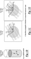
Figure 1A shows a plurality of diagrams providing an overview of the underlying mathematical relationships used to computationally design optical projections. These optical projections can be generated physically by various embodiments of the present disclosure to create a target intensity distribution. -
Figures 1B-1D illustrate the coordinate system that is used in the present disclosure to help describe the various embodiments; -
Figure 2A shows one embodiment of a system in accordance with the present disclosure that makes use of a system of light sources and lenses or other optics arranged circumferentially around a target resin volume, to simultaneously generate projections at each angle θ. The simultaneous superposition of 3D intensity maps emanating from all projections is used to cure selected portions of the resin in one operational step; -
Figure 2B shows a 3D representation of the embodiment inFigure 2A with the various optical projections passing through the target volume of resin at different angles θ; -
Figure 3 shows a high level diagram of another embodiment of the present disclosure in which the target resin volume container is rotated by a rotating mount or stage, while an optical projection generating component provides a single projection at a fixed time. This projection creates a 3D intensity field in the volume. As the resin volume rotates with time and the angle θ is changed, the projections are updated. -
Figure 4 shows a high level diagram of another embodiment of the present disclosure in which the target resin volume container is maintained stationary, and a rotating arm assembly directs optical projections from varying angles θ. - Corresponding reference numerals indicate corresponding parts throughout the several views of the drawings.
- Example embodiments will now be described more fully with reference to the accompanying drawings.
- The approach described in the present invention disclosure accomplishes volumetric fabrication by applying computed tomography (CT) techniques in reverse, that is, by fabricating structures by exposing a photopolymer resin volume with a 3D light field from multiple angles, and updating the light field at each angle. The necessary light fields are spatially and/or temporally multiplexed, such that their summed energy dose in a target resin volume crosslinks the resin into a user-defined geometry. These light fields may be static or dynamic, and may be generated by any suitable mechanism, for example a spatial light modulator (SLM). The SLM controls either the phase or the amplitude of a light field, or possibly both, to provide the necessary intensity distribution. The light fields at each angle θ may be generated simultaneously or sequentially in time. In the sequential case, they may be generated in any order. The present disclosure significantly advances the process possibilities in this area, providing a means to generate a 3D radiation dose distribution within a given volume, allowing for nearly arbitrary structures in photopolymer curing.
- This present disclosure is based on spatial and/or temporal multiplexing of three-dimensional (3D) optical light fields with respect to a photosensitive resin bath volume. Multiplexing can be accomplished in a number of ways including, but not limited to, those described in the specific embodiments and methods in the following paragraphs. Multiplexing may be implemented as to cure 3D user-designed geometries in situ in the photopolymer build volume by delivering a controlled exposure dose to selected regions of the resin.
- Conceptually, the teachings of the present disclosure build upon the well-developed field of computed tomography (CT). CT generally refers to imaging of a 3D volume from multiple angles, most often by X- rays transmitted through the volume, where each image is sequentially generated by illumination from azimuthally-arrayed directions. The 3D volume is then reconstructed by various known computational techniques. Such known computational techniques may include Fourier-domain methods such as filtered back-projection (FBP) or iterative optimization-based techniques. See, e.g., S.W. Smith, "The Scientist & Engineer's Guide to Digital Signal Processing," 1st Ed., San Diego, Calif: California Technical Pub, 1997. With CT approaches being useful for capturing and recording 3D geometrical information, computed axial lithography (CAL) inverts the concept to generate a 3D geometry from exposures of a photopolymer from multiple angles. The embodiments described herein retain the "volume-at-once" capability, while significantly improving the geometric flexibility of the three beam holographic lithography approach (Shusteff et al., supra), which eliminates conventional discretization "stairstep" artifacts.
- For cancer therapeutic purposes, CT optimization has been used to deliver intensity-modulated radiation therapy (IMRT), which delivers a targeted 3D distribution of radiation doses to specific regions within a patient's physiology, while minimizing the dose in non-target areas. See, e.g., T. Bortfeld, J. Bürkelbach, R. Boesecke, and W. Schlegel, "Methods of image reconstruction from projections applied to conformation radiotherapy," Phys. Med. Biol., Vol. 35, No. 10, pp. 1423-1434, Oct. 1990. The constraints of 3D lithographic fabrication are typically less stringent, suggesting that a similarly-specified 3D dose distribution of radiation can be used to cross-link a photosensitive resin.
- To understand the relationship between the
target 3D part geometry, and the computed projections, considerFigure 1A , as well as the coordinate system designations inFigures 1B-1D . For the following discussion, it is convenient to adopt a global Cartesian coordinate system (x,y,z) to refer to the 3D build volume and a rotated Cartesian coordinate system (x',y',z') whose orientation depends on the angle θ of the projection being considered. In these coordinate systems, z is the axis for azimuthal arraying of exposures at angles θ aroundvolume 10. For each angle θ, a projection is computed. At a particular angle θ, we define a projection as a two-dimensional function Pe(y',z) which fully determines a three-dimensional intensity map l θ (x,y,z) generated in the target volume (note that Pe depends on the angle θ but will be referred to as a two-dimensional function as it has two spatial dimensions). In the simplest case the projection can be thought of as a two dimensional image in the (y',z) domain which propagates through the resin volume in the x' direction. In this idealized case, the 3D intensity profile generated by the projection looks like the (y',z) domain image extruded through the target volume in the x' direction. This approximation holds well physically if the illuminating projections are collimated. In medical imaging applications, this is analogous to parallel beam tomography. For the present disclosure, this is a sufficiently good approximation whenever the optical configuration has a long depth of focus (particularly relevant for the small diffraction angles available with current SLM technology). In the general case, an optical propagation and attenuation model describes the 3D intensity map generated from a 2D projection function at a particular angle. In this description and inFigure 1A we consider the idealized case for simplicity in describing the method. - The objective of the tomographic image computation is to design a set P(y',z,θ) of 2D projection images from a range of angles θ such that the 3D intensity map generated from the superposition of the 3D light fields generated from each projection closely or exactly approximates a
target 3D intensity map. From a knowntarget 3D intensity map we now consider design of the projections. To further simplify the explanation, we reduce the problem of generating a set of 2D projections for a 3D intensity map to that of generating a set of 1D projections P(y',θ) for a 2D intensity map I(x,y). Again, in this case, 1D refers to the one spatial dimension y'. In the physical (x,y,z) resin volume system, we can think of the 2D intensity map as a horizontal constant z slice of the true 3D intensity map. Ultimately, the 2D projection Pθ (y',z) at a give angle θ can then be generated by stacking of each of the computed 1D projections at each z-plane for that particular angle. - Among the many ways to accomplish CT image reconstruction, two major approaches that lend themselves readily to dose-optimization for fabrication are filtered back-projection (FBP) and iterative optimization-based algorithms. Here we first consider the FBP approach and its limitations, and describe how it may be used to provide useful starting parameters for an optimization algorithm.
- The FBP approach for reconstructing a 2D optical density distribution within an (x,y) plane for a given value of z starts with computing a mathematical 1D projection at each of M angular samples (θ = θ1 , θ2, ... θM ). These projections taken together comprise the Radon transform of the 2D image. From the projection slice theorem, as discussed in R. Bracewell, "Strip Integration in Radio Astronomy," Aust. J. Phys., Vol. 9, No. 2, p. 198, 1956 and R. N. Bracewell, "Numerical Transforms," Science, Vol. 248, No. 4956, pp. 697-704, May 1990, it is known that the Fourier transform of each 1D projection at a particular angle θ is exactly equal to a 1D sample of the Fourier transform of the original 2D density distribution. This 1D sample lies along a line through the origin in the Fourier domain and is sloped at an angle θ. This is depicted in
Figure 1A . Sufficiently dense sampling in the Fourier domain is required for an accurate CT image reconstruction. To appropriately choose the number of samples M in the Fourier domain, one possible conservative heuristic is to ensure that the maximum distance between slices is no greater than the separation of N sample points in the radial direction. This leads to πN/2 angular samples within 180 degrees of angular range. - The lithographic fabrication of each 2D z plane can follow an algorithmic time reversal of the CT imaging process. The
target 2D Intensity map for the slice Iz(x,y) is transformed into the Fourier domain, then sampled along each of the M azimuthal angles, generatingM 1D intensity distributions, or projections Pe(y'), one for each angle θ1, θ2,... θM. Each of these distributions is used to expose the target plane with its respective pattern from its specific angle, which corresponds to building up the sample in the Fourier domain from slices through the origin. FBP for CT reconstruction relies on high-pass spatial filtering before back-projection in order to deemphasize the low frequency oversampling inherent to the central slicing approach. An equivalent way to describe this would be as a radially increasing ramp filter. This filter typically leads to negative excursions in the back-projected images that are unphysical for lithography. Some heuristic approaches to eliminate negative values, producing images suitable for lithography, include imposed positivity constraints or offsetting the calculated image. The results of such heuristics impose trade-offs between the contrast and resolution of calculated dose distributions; however, they can be used as initial dose estimates for a constrained optimization procedure. - Briefly, an optimization procedure takes as its starting point a forward process model that relates resin monomer crosslinking to the received light energy dose. Various 2D versions of such models, such as discussed at D. Dendukuri, P. Panda, R. Haghgooie, J. M. Kim, T. A. Hatton, and P. S. Doyle, "Modeling of Oxygen-Inhibited Free Radical Photopolymerization in a PDMS Microfluidic Device," Macromolecules, Vol. 41, No. 22, pp. 8547-8556, Nov. 2008, available, with limited progress toward 3D analogs. Comparing the modeled degree of cure (induced by the summed dose distribution from all angles), to the desired part geometry, an error function is generated, which is reverse-transformed and used to modify the initial dose estimate. This cycle is iterated for a number of cycles sufficient to meet a particular error criterion, such as edge sharpness, contrast, or total error over the build volume. The optimization procedure provides a means for process non-linearities such as intensity absorption to be accurately modeled and accounted for in the image generation. This is a significant benefit in terms of feature quality. The extension from 2D planes into 3D is straightforward, with the 1D intensity patterns from each z plane assembled into a 2D y'-z image for projection at every angle θ corresponding to the particular x' propagation direction. Effectively, this is a physical projection of the computed Radon transforms for all z planes at each angle θ to reconstruct the desired 3D dose volume.
- One specific embodiment, which is not covered by the claims, but which implements the above described method is
system 24 shown inFigure 2A . Thesystem 24 may include a plurality ofoptical subsystems 26 arranged such that a set of optical projections P(y',z,θ) at specific selected angles θ 1, θ 2, ... θM,. is generated around a target volume ofresin 29 contained within an opticallytransparent container 29a. One possible design of theoptical subsystems 26 may include anOLED array 27 covered bymicrolenses 28 surrounding the 3D target volume ofresin 29. TheOLED arrays 27 may be controlled in part by acontroller 26a. Different groups of theoptical subsystems 26 simultaneously generate projections P θ (y',z) and corresponding 3D intensity maps le(x,y,z) 261, 262, 263, etc., at different angles θ1, θ2, θ3, respectively, etc., that project through thetarget resin volume 29, as shown inFigure 2B . The projections Pθ (y',z) and Intensity maps I θ (x,y,z) are analogous to those described in section [0019].Figure 2B illustrates the 2D nature of each of theoptical projections projections target resin volume 29 contained within theresin container 29a simultaneously from M different angles θ (i.e., two or more) about the z-axis (Figure 2B ). The simultaneous superposition of the 3D intensity fields 261, 262, 263, etc., from all angles around the full 360 degree circumference of thetarget resin volume 29, as indicated inFigure 2A , generates a 3D intensity function I(x,y,z) in space. This intensity function acts over a fixed temporal exposure period. During exposure, regions where material formation is desired receive a sufficient optical energy dose to cause solidification due to photocuring, while regions where formation (i.e., curing) is not desired receive an insufficient dose. After the exposure period, theresin container 29a may be rinsed to remove uncured resin from regions of the 3D part which have received an insufficient dose of optical energy to achieve photocuring. - Further underlying information on light field photography and 3D displays may be found in Ng, R., 2006. "Digital Light Field Photography (Doctoral dissertation, Stanford University) and Lanman, D. and Luebke, D., 2013 "Near-eye light field displays" (ACM Transactions on Graphics (TOG)), Vol. 32, No. 6, p. 220. This information is relevant to the possibility of creating the necessary optical subsystems from arrays of LEDs covered by microlenses. The
system 24 thus forms a means of simultaneously generating images from many viewpoints and simultaneously exposing the entire target volume ofresin 29 to theprojections projection - By printing in a single step and avoiding serial layer-by-layer printing, a number of potential issues which may arise in existing AM methods can be addressed. These include difficulties in printing overhang geometries as well as avoiding layering artifacts such as poor surface finish and mechanical anisotropies. An additional benefit of this approach is that the structure being built does not move relative to the fluid medium, enabling fabrication of very compliant or fragile components such as low-volume fraction hydrogel scaffolds (combined with suitable rinsing/drying approaches, such as solvent exchange followed by supercritical CO2 drying).
- Referring to
Figure 3 , asystem 30 is shown which generates a 3D exposure dose distribution over a fixed time interval by physical rotation of a target volume ofresin 32 abouta z axis 42, synchronized via acontroller 31 with temporal manipulation of a single 2D optical projection from a digital light processing (DLP) projector or other image generationoptical system 34. In the implementation as described previously herein, the image generationoptical system 34 produces a collimated optical image orprojection 36 from a single direction along an axis x' 41 that impinges on the target volume ofresin 32. It will be appreciated that the images could also have some divergence (i.e., not collimated) and the algorithm to design them could be updated accordingly. - The relative angle θ between the incident light of the
projection 36 and the target volume ofresin 32 is changed in time as different (y',z) plane images are sequentially projected. Following the coordinate system convention described earlier and depicted inFigure 1B, 1C, and 1D , the (x,y,z) system rotates about the z axis as the target volume ofresin 32 rotates and the (x',y',z) system remains fixed in space. Thus, as the target volume ofresin 32 rotates, the angle θ between the x-axis and x'-axis changes. In one example, aresin containment vessel 38 that holds the target volume ofresin 32 is mounted on a rotating mount orstage 40. The rotating stage rotates aboutz axis 42 and operation of theDLP projector 34 is synchronized with rotation of themount 40 by thecontroller 31. Thecontainment vessel 38 may be submerged within asecond containment vessel 44 which contains a fluid 46 with the same (or similar) refractive index as theresin 32. This provides a flat interface where the refractive index changes and mitigates lensing effects which would arise at a curved interface of mismatched refractive index. Note that in the description of the above system, the coordinate notation is such that the x'-axis is stationary while the (x,y,z) coordinate system rotates with theresin containment vessel 38. - Another embodiment of the
system 30 shown inFigure 3 may involve the use of a plurality of DLP projectors 34 (i.e., a plurality of optical subsystems) positioned to face each of the four vertical sides of thesecond containment vessel 44, to generate the plurality of optical 2D projections. Still another embodiment may involve a modification to thesystem 30 shown inFigure 3 in which thecontainment vessel 38 and thesecond containment vessel 44 are both held stationary, while the DLP projector 34 (i.e., the optical subsystem) is rotated on a doughnut shapedsupport 34a around the full circumference of thecontainment vessel 38 to produce the plurality of optical 2D projections. - Still another variation of the embodiment shown in
Figure 3 may involve using photo-degradable (i.e., photo-responsive) material instead of a resin. This variation of the embodiment is not covered by the claims. For example, one might start with a solid 3D block of photo-degradable material and use optical 2D projections as described herein to remove only certain portions of the solid 3D block to produce a desired 3D part. Such materials are used, for example, in tissue engineering. - Referring to
Figure 4 , asystem 50 in accordance with another embodiment of the present disclosure is shown. With thesystem 50, aresin volume 52 is contained within astationary container 54. Asecondary container 55 may be used to hold an additional quantity offluid 55a which has the same (or similar) refractive index as theresin volume 52. Anoptical subsystem 56, produces anoptical projection 58 along and x axis (fixed relative to the stationary target volume). The 3D intensity map generated by the projection is rotated around the resin volume 52 (i.e., aboutz axis 60, and propagating along a rotating x'-axis 61) via arotating arm assembly 50a. Astationary mirror 62 receives theprojection 58 and feeds it to a collection of mirrors 64-68 contained within therotating arm assembly 50a. The mirrors 64-68 direct theprojection 58 to illuminate the resin volume. As the arm rotates, y'-z plane images are projected at many angles θ about the full circumference. As is the case with the other embodiments, the net exposure dose from the sum of the 3D intensity distributions generated from all of the projections over one rotation is such that regions where material formation is desired receive a sufficient dose to photo crosslink the resin while other regions receive an insufficient dose. Spatial and temporal modulation of the projections (i.e., modulation of image intensity of the 2D (y'-z) images being projected) 58 at each angle θ is controlled in the same way as described above forFigures 2A-2B , for example, by means of a spatial light modulator (SLM) 70 or DLP projector. Thesystem 50 allows for potentially much faster rotation speeds compared to the methodology described in connection withFigure 3 , as fluid motion considerations are eliminated. Compared to the methodology described in connection withFigures 2A-2B , thesystem 50 offers the advantage of a simpler optical system based in prior art. The proposed configuration shown inFigure 4 can be applied with one or more simultaneously rotating optical projections. Similarly to the methodology described in connection withFigures 2A and 2B theresin container 54 does not move relative to the fluid during fabrication, so the formation of more fragile, delicate or compliant structures is possible. - Finally, the optical signal multiplexing necessary to achieve Computed Axial Lithography could be performed by systems which share features of any or all of the embodiments described above. As one example, a light field projection display (
Figures 2A-2B ) which does not span a full 360° of angular projection could be combined with a rotating vial, similar to what is used withsystem 30 ofFigure 3 , in order to expand the angular range. For example, consider the use of a curved display such as shown infigures 2A and 2B , which instead of having a cylindrical shape looks like a half-cylinder or a smaller angular section of a cylinder. It still projects images from multiple angles simultaneously but the range of angles spans less than 360 degrees (in the half cylinder case it's 180 degrees). However if that display is rotated about the resin volume and the projections are updated in time, then it is possible to span a full 360 degrees, even faster than what could likely be achievable in the embodiment shown inFigure 4 . Such an embodiment would likely not print as fast as theFigure 2 embodiment but it may be easier to fabricate. Similarly, target volume of resin could remain static while the < 360 degree projection display is rotated about the volume. - The system and method of the present disclosure surpasses recently reported volumetric aperiodic three-dimensional (3D) structure fabrication using holographic light fields in its geometric flexibility. Similarly, the inherently volume-based approach of the present disclosure provides an order of magnitude improvement in fabrication speed over conventional layer-by-layer "2 1/2D" printing techniques. Finally, the surface roughness problems imposed by layer-by-layer fabrication are substantially reduced if not removed entirely.
- The system and method of the present disclosure is expected to find utility in a number of applications. For example, the system and method of the present disclosure provides an improvement to photopolymer-based additive manufacturing in a number of important aspects, such as more rapid part generation, improved surface quality (e.g., no "stair step" artifacts from layering), and a reduction of geometric constraints that arise from 2D layer slicing and simplified post-processing. Potential applications of the various embodiments and methods described herein may involve AM generated optics with high quality surface finish; hollow or overhanging structures; large dynamic range mesoscale AM structures; printing/fabrication on a previously fabricated 3D structure immersed in a resin; and processing soft, flexible or brittle polymers and geometrically delicate/fragile structures (as there is no relative structure/fluid motion during printing).
- The foregoing description of the embodiments has been provided for purposes of illustration and description. It is not intended to be exhaustive or to limit the disclosure. Individual elements or features of a particular embodiment are generally not limited to that particular embodiment.
Claims (13)
- A method of forming a three dimensional object, comprising:providing a volume of photo-curable resin (32;52) contained within an optically transparent resin container (38;54), a z axis (42;60) extending through the volume of photo-curable resin (32;52) and an x' axis (41;61) extending normal to the z axis (42;60);using an optical subsystem (34;56) to generate an optical two dimensional projection (36;58);causing the optical two dimensional projection or the resin container (38;54) to rotate relative to the other to receive the optical two dimensional projection (36;58) around a complete circumference of the volume of photo-curable resin (32;52) while maintaining the optical two dimensional projection (36;58) directed through the volume of photo-curable resin (32;52),wherein rotating the two dimensional projection or the resin container (38;54) to move relative to the other comprisesa) mounting the resin container (38) on a rotating mount or stage (40) and physical rotation of the resin container (38) about the z axis (42), orb) rotating the optical subsystem (34) circumferentially about the resin container (38) to direct the optical two dimensional projections toward the volume of photo-curable resin (32) from the plurality of angles while the resin container (38) is held stationary, orc) using a rotating arm assembly (50a) having a plurality of mirrors (64,66,68) configured to direct the optical two dimensional projections toward the volume of photo-curable resin (52) while the resin container (54) and the optical subsystem (56) are both held stationary,andwherein a two dimensional projection function of the optical two dimensional projection (36;58) is controlled at each angle θ to deliver a controlled three dimensional exposure dose over a fixed temporal exposure period, and where a plurality of two dimensional projections is generated from a plurality of angles θ, and where the plurality of two dimensional projections are summed to produce a three dimensional exposure dose in the volume of photo-curable resin (32;52) which is sufficient to cause photocuring in desired regions, while being insufficient to cause photocuring in undesired regions.
- The method of claim 1, wherein, in case of using the rotating arm assembly (50a), the rotating arm assembly (50a) receives the optical two dimensional projections (58) from a stationary mirror (62).
- The method of claim 1, wherein, in case of a), directing two dimensional projections from the optical subsystem (34) comprises directing optical two dimensional projections from a stationary digital light processing projector.
- The method of claim 1, wherein, in case of using the rotating arm assembly (50a), directing optical two dimensional projections from the optical subsystem (56) comprises directing optical two dimensional projections from the optical subsystem (56) using a spatial light modulator (70) which controls the amplitude of the impinging light source or the phase or both.
- The method of claim 1, further comprising arranging the resin container (38;54) within a second container (44;55), the second container (44;55) containing a fluid (46;55a) having a refractive index matched to that of the resin.
- The method of claim 1, wherein a computational design of optical two dimensional projections delivered from the optical subsystem at the plurality of angles θ comprises:generating a one dimensional intensity pattern for a particular z plane at each angle θ, for each one of a plurality of z planes extending through the z axis; andassembling the one dimensional intensity patterns for a particular angle θ, for each z plane, into a two dimensional image projection from the particular angle θ, and repeating the generating and assembling operations for each angle θ.
- The method of claim 1, wherein a computational design of optical projections delivered from an optical subsystem at the plurality of angles θ comprises:
using Fourier-domain methods including filtered back-projection or iterative optimization-based techniques. - A system for forming a three dimensional object from a volume of photo-curable resin (32;52), the system comprising:an optically transparent resin container (38;54) for containing the volume of photo-curable resin (32;52), and wherein a z axis (42;60) extends through the volume of photo-curable resin (32;52) and an x' axis (41;61) extends normal to the z axis (42;60);a controller (31);an image generation optical system including an optical subsystem (34;56) controlled by the controller (31) for generating a plurality of optical two dimensional projections (36;58), with each said optical two dimensional projection (36;58) forming an optical image, and being aimed at the optically transparent material container (38;54); andwherein relative rotation is created between the two dimensional projection (36;58) and the resin container (38;54) by the controller (31) to cause the optical two dimensional projections (36;58) to be received around a complete circumference of the volume of photocurable resin (32;52), while the optical two dimensional projections are directed through the volume of photocurable resin (32;52), wherein the creating of the relative rotation comprisesa) mounting the resin container (38) on a rotating mount or stage (40) and physical rotation of the resin container (38) about the z axis (42), orb) rotating the optical subsystem (34) circumferentially about the resin container (38) to direct the optical two dimensional projections toward the volume of photo-curable resin (32) from the plurality of angles while the resin container (38) is held stationary, orc) using a rotating arm assembly (50a) having a plurality of mirrors (64,66,68) configured to direct the optical two dimensional projections toward the volume of photo-curable resin (52) while the resin container (54) and the optical subsystem (56) are both held stationary,andwherein a two-dimensional projection function of the two dimensional projection is controlled at each angle θ to deliver a controlled three dimensional exposure dose over a fixed temporal exposure period, and where the plurality of two dimensional projections is generated from a plurality of angles θ, and where the plurality of two dimensional projections are summed to produce a three dimensional exposure dose in the volume of photo-curable resin (32;52) which is sufficient to cause photocuring in desired regions, while being insufficient to cause photocuring in undesired regions.
- The system of claim 8, wherein, in case of a), the image generation optical system (34) comprises a stationary digital light processing projector.
- The system of claim 8, wherein, in case of using the rotating arm assembly (50a), the image generation optical system comprises a stationary spatial light modulator (70) wherein the amplitude of the impinging light source or the phase or both are controllable.
- The system of claim 8, wherein the controller (31) controls the image generation optical system to generate the two dimensional optical projections, at a plurality of angles θ, by:generating a one dimensional intensity pattern for a particular z plane at each angle θ, for each one of a plurality of z planes extending through the z axis; andassembling the one dimensional intensity patterns for a particular angle θ, for each z plane, into a two dimensional image projection from that angle θ, and repeating the generating and assembling operations for each angle θ.
- The system of claim 8, wherein the controller (31) is configured to use Fourier-domain methods including at least one of a filtered back-projection technique or iterative optimization-based techniques, to cause the optical system to deliver the optical projections at a plurality of angles θ.
- The system of claim 8, further comprising a secondary container (44;55), in which the optically transparent material container (38;54) is disposed, where the secondary container (44;55) is filled with a fluid (46;55a) which has a refractive index matched to that of the resin.
Priority Applications (1)
| Application Number | Priority Date | Filing Date | Title |
|---|---|---|---|
| EP24196532.6A EP4442462A3 (en) | 2017-05-12 | 2018-03-27 | System and method for computed axial lithography (cal) for 3d additive manufacturing |
Applications Claiming Priority (2)
| Application Number | Priority Date | Filing Date | Title |
|---|---|---|---|
| US15/593,947 US10647061B2 (en) | 2017-05-12 | 2017-05-12 | System and method for computed axial lithography (CAL) for 3D additive manufacturing |
| PCT/US2018/024475 WO2018208378A2 (en) | 2017-05-12 | 2018-03-27 | System and method for computed axial lithography (cal) for 3d additive manufacturing |
Related Child Applications (2)
| Application Number | Title | Priority Date | Filing Date |
|---|---|---|---|
| EP24196532.6A Division EP4442462A3 (en) | 2017-05-12 | 2018-03-27 | System and method for computed axial lithography (cal) for 3d additive manufacturing |
| EP24196532.6A Division-Into EP4442462A3 (en) | 2017-05-12 | 2018-03-27 | System and method for computed axial lithography (cal) for 3d additive manufacturing |
Publications (4)
| Publication Number | Publication Date |
|---|---|
| EP3634720A2 EP3634720A2 (en) | 2020-04-15 |
| EP3634720A4 EP3634720A4 (en) | 2020-12-30 |
| EP3634720C0 EP3634720C0 (en) | 2024-10-30 |
| EP3634720B1 true EP3634720B1 (en) | 2024-10-30 |
Family
ID=64097030
Family Applications (2)
| Application Number | Title | Priority Date | Filing Date |
|---|---|---|---|
| EP18797947.1A Active EP3634720B1 (en) | 2017-05-12 | 2018-03-27 | System and method for computed axial lithography (cal) for 3d additive manufacturing |
| EP24196532.6A Pending EP4442462A3 (en) | 2017-05-12 | 2018-03-27 | System and method for computed axial lithography (cal) for 3d additive manufacturing |
Family Applications After (1)
| Application Number | Title | Priority Date | Filing Date |
|---|---|---|---|
| EP24196532.6A Pending EP4442462A3 (en) | 2017-05-12 | 2018-03-27 | System and method for computed axial lithography (cal) for 3d additive manufacturing |
Country Status (9)
| Country | Link |
|---|---|
| US (3) | US10647061B2 (en) |
| EP (2) | EP3634720B1 (en) |
| JP (3) | JP7019725B2 (en) |
| KR (2) | KR102525487B1 (en) |
| CN (2) | CN110891761B (en) |
| AU (2) | AU2018266447B2 (en) |
| CA (1) | CA3063391A1 (en) |
| ES (1) | ES3004534T3 (en) |
| WO (1) | WO2018208378A2 (en) |
Families Citing this family (75)
| Publication number | Priority date | Publication date | Assignee | Title |
|---|---|---|---|---|
| US20180153205A1 (en) * | 2015-04-28 | 2018-06-07 | Xiang Wu | Imaging and forming method using projection operation and back projection method |
| CN114654721A (en) * | 2017-08-30 | 2022-06-24 | 洛桑联邦理工学院 | Method and apparatus for three-dimensional fabrication by tomographic back-projection |
| WO2019133422A2 (en) | 2017-12-29 | 2019-07-04 | Eos Of North America, Inc. | Additive manufacture system using light valve device |
| WO2019145795A2 (en) | 2018-01-26 | 2019-08-01 | Cellink Ab | Systems and methods for optical assessments of bioink printability |
| EP3627227A1 (en) * | 2018-09-24 | 2020-03-25 | Stichting Nederlandse Wetenschappelijk Onderzoek Instituten | Controlled polymerization of a target zone in a photopolymerizable medium |
| US11186736B2 (en) | 2018-10-10 | 2021-11-30 | Cellink Ab | Double network bioinks |
| EP3691860B1 (en) | 2018-11-06 | 2023-07-19 | École Polytechnique Fédérale De Lausanne (EPFL) | Photoresponsive materials for volumetric additive manufacturing |
| EP3877179B1 (en) | 2018-11-06 | 2023-11-01 | Ecole Polytechnique Federale De Lausanne (Epfl) | Methods and apparatus for tomographic additive manufacturing with a spatially coherent light source |
| EP3914437B1 (en) * | 2019-01-24 | 2023-12-06 | Walter Voit | System for additive manufacturing |
| WO2020243748A1 (en) | 2019-05-31 | 2020-12-03 | The Procter & Gamble Company | Methods of making a deflection member |
| WO2020244037A1 (en) * | 2019-06-04 | 2020-12-10 | 浙江大学 | Imaging principle-based integrated color light 3d bioprinting system |
| CN110228193B (en) * | 2019-06-04 | 2021-10-15 | 浙江大学 | An integrated color light 3D bioprinting system based on imaging principle |
| CN117301517A (en) | 2019-06-06 | 2023-12-29 | 效洛有限公司 | Equipment for localized polymerization of starting materials by two-color photopolymerization |
| CN113993689A (en) * | 2019-06-21 | 2022-01-28 | 洛桑联邦理工学院 | System and method for correcting three-dimensional objects in a volume tomography printer using feedback |
| EP3766669B1 (en) | 2019-07-18 | 2024-08-14 | Bostik Sa | 3d-printing methods and systems |
| US12472686B2 (en) | 2019-08-06 | 2025-11-18 | Ecole Polytechnique Federale De Lausanne | Method and apparatus for volumetric additive manufacturing of cell-loaded resins |
| US11826951B2 (en) | 2019-09-06 | 2023-11-28 | Cellink Ab | Temperature-controlled multi-material overprinting |
| WO2021058437A1 (en) | 2019-09-24 | 2021-04-01 | Ecole Polytechnique Federale De Lausanne (Epfl) | Method and apparatus for volumetric additive manufacturing with digital distortion compensation |
| AU2020353167A1 (en) * | 2019-09-27 | 2022-04-21 | Prellis Biologics, Inc. | Three-dimensional printed organs, devices, and matrices |
| US11125407B1 (en) | 2020-03-10 | 2021-09-21 | Ford Global Technologies, Llc | Vehicle lamp assembly |
| US11472120B2 (en) * | 2020-05-07 | 2022-10-18 | Kyndryl, Inc. | Light-based 3D printing |
| US11809161B2 (en) * | 2020-07-13 | 2023-11-07 | Lawrence Livermore National Security, Llc | Computed axial lithography optimization system |
| US12343941B2 (en) | 2020-10-27 | 2025-07-01 | Danmarks Tekniske Universitet | Tomographic vat photopolymerization for 3D printing of objects with internal property-variation |
| WO2022147625A1 (en) | 2021-01-08 | 2022-07-14 | National Research Council Of Canada | A method for correcting ray distortions in tomographic 3d printing |
| EP4029675B1 (en) | 2021-01-19 | 2024-05-29 | Bostik SA | 3d-printing methods and systems |
| EP4291389A4 (en) * | 2021-02-12 | 2025-01-22 | Seurat Technologies, Inc. | PHASE-MANAGED GENERATIVE PRINTING SYSTEM |
| US20240239039A1 (en) | 2021-05-17 | 2024-07-18 | Ecole Polytechnique Federale De Lausanne (Epfl) | High resolution and three-dimensional printing in complex photosensitive materials |
| US11845222B2 (en) | 2021-05-21 | 2023-12-19 | Igneous IP Holdings, LLC | Increasing throughput in additive manufacturing using a rotating build platform |
| EP4363221A1 (en) | 2021-07-01 | 2024-05-08 | Readily3D SA | System and method for the fabrication of aligned structures by optical modulation instability |
| EP4395977A1 (en) * | 2021-09-03 | 2024-07-10 | Readily3D SA | Method for digital analytic correction of photoresponsive material reactivity in additive manufacturing |
| WO2023076570A1 (en) | 2021-10-28 | 2023-05-04 | Align Technology, Inc. | Systems and methods for post-processing additively manufactured objects |
| WO2023164569A1 (en) | 2022-02-23 | 2023-08-31 | Align Technology, Inc. | Control systems for additive manufacturing and associated methods |
| CN114851550A (en) * | 2022-04-19 | 2022-08-05 | 广州医科大学 | A volumetric three-dimensional bioprinting device and printing method |
| CN120051257A (en) | 2022-08-15 | 2025-05-27 | 阿莱恩技术有限公司 | Method for producing additive manufactured objects with heterogeneous properties |
| EP4587222A2 (en) | 2022-09-15 | 2025-07-23 | Align Technology, Inc. | Systems and methods for modifying surfaces of additively manufactured objects |
| US12605889B2 (en) | 2022-09-22 | 2026-04-21 | Align Technology, Inc. | Modular build platforms for additive manufacturing |
| EP4594083A1 (en) | 2022-09-27 | 2025-08-06 | Danmarks Tekniske Universitet | System and methods for tomographic vat photopolymerization |
| WO2024086752A1 (en) | 2022-10-20 | 2024-04-25 | Align Technology, Inc. | Systems and methods for generating directly manufacturable dental appliances |
| US12472720B2 (en) | 2022-10-26 | 2025-11-18 | Align Technology, Inc. | Materials and additively manufactured objects with mechanically interlocking elements |
| US12576585B2 (en) | 2022-10-26 | 2026-03-17 | Align Technology, Inc. | Additive manufacturing systems with fixed substrates |
| CN115635680A (en) * | 2022-10-26 | 2023-01-24 | 北京京东方技术开发有限公司 | Photocuring equipment and photocuring method |
| US12600094B2 (en) | 2022-11-01 | 2026-04-14 | Align Technology, Inc. | Prefabricated support structures and/or overlays for additive manufacturing |
| CN115847807B (en) * | 2022-12-09 | 2023-10-27 | 湖南大学 | Method of composite material additive manufacturing system based on volume printing principle |
| CN120858020A (en) | 2023-01-09 | 2025-10-28 | 阿莱恩技术有限公司 | Method for generating a support structure for an additively manufactured object |
| WO2024173543A2 (en) | 2023-02-15 | 2024-08-22 | Align Technology, Inc. | Monomer compounds for 3d printing resins |
| CN121002083A (en) | 2023-02-28 | 2025-11-21 | 阿莱恩技术有限公司 | Additives for 3D printing polymer resins |
| EP4673082A1 (en) | 2023-03-01 | 2026-01-07 | Solventum Intellectual Properties Company | Ceramic veneers and continuous additive manufacturing method for making ceramic veneers |
| CN116198128A (en) * | 2023-03-01 | 2023-06-02 | 诺丁汉大学卓越灯塔计划(宁波)创新研究院 | Holographic 3D printer and 3D printing method |
| EP4676715A1 (en) | 2023-03-10 | 2026-01-14 | Align Technology, Inc. | Additive manufacturing systems with error correction and associated methods |
| EP4676717A1 (en) | 2023-03-10 | 2026-01-14 | Align Technology, Inc. | Methods and devices for additive manufacturing |
| US20240352174A1 (en) | 2023-03-14 | 2024-10-24 | Align Technology, Inc. | Crosslinkers and compositions |
| WO2024192136A1 (en) | 2023-03-14 | 2024-09-19 | Align Technology, Inc. | Photocurable polymers and compositions for 3d printing resins |
| CN120936480A (en) | 2023-04-05 | 2025-11-11 | 丹麦科技大学 | Print volume expansion using multiple projectors in tomographic volume 3D printing |
| WO2024216082A1 (en) | 2023-04-14 | 2024-10-17 | Align Technology, Inc. | Systems and methods for designing objects |
| CN116423824B (en) * | 2023-05-30 | 2026-03-20 | 江南大学 | Optical elements with complex structures and their molding methods |
| US20250018650A1 (en) | 2023-07-13 | 2025-01-16 | Align Technology, Inc. | Systems for cleaning and/or cooling additively manufactured objects and associated methods |
| CN116945609B (en) * | 2023-08-04 | 2024-02-13 | 绿钥生物科技(广州)有限公司 | Projection slice generation method, device, equipment and storage medium suitable for volume biological 3D printing |
| DE102023121854A1 (en) | 2023-08-16 | 2025-02-20 | Xolo Gmbh | Method for producing a three-dimensional object |
| CN117207529B (en) * | 2023-09-28 | 2025-05-06 | 绿钥生物科技(广州)有限公司 | A volumetric bioprinting control method |
| CN117183334B (en) * | 2023-09-28 | 2025-07-01 | 绿钥生物科技(广州)有限公司 | Printing effect evaluation method and device suitable for volume biological printing projection |
| CN117207528B (en) * | 2023-09-28 | 2025-05-06 | 绿钥生物科技(广州)有限公司 | Volume biological printing light intensity distribution control method based on projection algorithm |
| WO2025075925A1 (en) | 2023-10-02 | 2025-04-10 | Align Technology, Inc. | Methods for stabilizing additively manufactured objects |
| WO2025122507A1 (en) | 2023-12-04 | 2025-06-12 | Align Technology, Inc. | Additively manufactured objects with accessible supports and associated methods |
| EP4567515A3 (en) | 2023-12-05 | 2025-08-20 | Xolo GmbH | Composition comprising naphthopyran photoswitchable photoinitiators and thiols for locally polymerizing a starting material by dual color photopolymerization |
| EP4566819A1 (en) | 2023-12-05 | 2025-06-11 | Xolo GmbH | Naphthopyran photoswitchable photoinitiators for locally polymerizing a starting material by dual color photopolymerization |
| US20250222655A1 (en) | 2024-01-04 | 2025-07-10 | Align Technology, Inc. | Predicting manufacturing outcomes for additively manufactured objects |
| US20250276378A1 (en) | 2024-02-29 | 2025-09-04 | Cubicure Gmbh | Attachment mechanisms for modular build platforms |
| WO2025207660A2 (en) | 2024-03-26 | 2025-10-02 | Align Technology, Inc. | Methods for producing phenolic compounds including syringol from biomass and using same for 3d printing |
| WO2025223658A1 (en) | 2024-04-25 | 2025-10-30 | Ecole Polytechnique Federale De Lausanne (Epfl) | System and method for high throughput and high-resolution volumetric additive manufacturing using time multiplexed computer-generated holograms |
| WO2025264582A2 (en) | 2024-06-17 | 2025-12-26 | Align Technology, Inc. | Recovery of hydroxyl-containing compounds and (meth)acrylate monomers from 3d printed polymeric material |
| WO2025264579A1 (en) | 2024-06-17 | 2025-12-26 | Align Technology, Inc. | Compositions for additive manufacturing with activatable fillers |
| US20260061703A1 (en) | 2024-08-30 | 2026-03-05 | Align Technology, Inc. | Bubble removal systems and methods for additive manufacturing |
| US20260084379A1 (en) | 2024-09-20 | 2026-03-26 | Align Technology, Inc. | Stochastic discretization of object slices for additive manufacturing |
| EP4725681A1 (en) | 2024-10-10 | 2026-04-15 | Xolo GmbH | Process for volumetric printing of a bio-compatible starting material |
| WO2026078149A1 (en) | 2024-10-10 | 2026-04-16 | Xolo Gmbh | Process for volumetric printing of a bio-compatible starting material |
Family Cites Families (29)
| Publication number | Priority date | Publication date | Assignee | Title |
|---|---|---|---|---|
| US4041476A (en) | 1971-07-23 | 1977-08-09 | Wyn Kelly Swainson | Method, medium and apparatus for producing three-dimensional figure product |
| US5011635A (en) * | 1989-05-18 | 1991-04-30 | Desoto, Inc. | Stereolithographic method and apparatus in which a membrane separates phases |
| JPH04267132A (en) * | 1991-02-22 | 1992-09-22 | Seiko Epson Corp | Three dimensional object-forming device |
| EP0451681B1 (en) * | 1990-04-05 | 1997-11-05 | Seiko Epson Corporation | Optical apparatus |
| US5217653A (en) * | 1991-02-18 | 1993-06-08 | Leonid Mashinsky | Method and apparatus for producing a stepless 3-dimensional object by stereolithography |
| JP2001322177A (en) | 2000-05-17 | 2001-11-20 | Minolta Co Ltd | Three-dimensional modeling method and three-dimensional modeling apparatus |
| US8289274B2 (en) | 2004-01-13 | 2012-10-16 | Sliwa John W | Microdroplet-based 3-D volumetric displays utilizing emitted and moving droplet projection screens |
| JP5018076B2 (en) * | 2006-12-22 | 2012-09-05 | ソニー株式会社 | Stereolithography apparatus and stereolithography method |
| EP2151214B1 (en) | 2008-07-30 | 2013-01-23 | Ivoclar Vivadent AG | Light hardening dross for stereolithographic production of dental ceramics |
| JP2010036537A (en) * | 2008-08-07 | 2010-02-18 | Roland Dg Corp | Photo-fabricating apparatus |
| US9492969B2 (en) * | 2010-05-28 | 2016-11-15 | Lawrence Livermore National Security, Llc | High resolution projection micro stereolithography system and method |
| JP5774825B2 (en) * | 2010-08-19 | 2015-09-09 | ソニー株式会社 | Three-dimensional modeling apparatus and manufacturing method of modeled object |
| US8579620B2 (en) | 2011-03-02 | 2013-11-12 | Andy Wu | Single-action three-dimensional model printing methods |
| US9179126B2 (en) | 2012-06-01 | 2015-11-03 | Ostendo Technologies, Inc. | Spatio-temporal light field cameras |
| US9778573B2 (en) * | 2013-03-14 | 2017-10-03 | The United States Of America As Represented By The Department Of Veterans Affairs | Optical illumination system |
| GB2514139A (en) * | 2013-05-14 | 2014-11-19 | Aghababaie Lin & Co Ltd | Apparatus for fabrication of three dimensional objects |
| WO2015072921A1 (en) | 2013-11-14 | 2015-05-21 | Structo Pte. Ltd | Additive manufacturing device and method |
| WO2015113408A1 (en) * | 2014-01-28 | 2015-08-06 | 上海普利生机电科技有限公司 | Light-curing type 3d printing device and image exposure system thereof |
| US20150228226A1 (en) * | 2014-02-13 | 2015-08-13 | Nvidia Corporation | Power-efficient steerable displays |
| TWI526294B (en) * | 2014-04-15 | 2016-03-21 | 三緯國際立體列印科技股份有限公司 | Three dimensional printing apparatus |
| JP6791840B2 (en) | 2014-08-14 | 2020-11-25 | エムティティ イノベーション インコーポレイテッドMtt Innovation Incorporated | light source |
| US20160067922A1 (en) | 2014-09-09 | 2016-03-10 | Disney Enterprises, Inc. | Three dimensional (3d) printing by volumetric addition through selective curing of a fluid matrix |
| US9656422B2 (en) * | 2014-10-21 | 2017-05-23 | Disney Enterprises, Inc. | Three dimensional (3D) printer with near instantaneous object printing using a photo-curing liquid |
| SG11201703716QA (en) * | 2014-11-07 | 2017-06-29 | Uvlrx Therapeutics Inc | High efficiency optical combiner for multiple non-coherent light sources |
| US10040239B2 (en) * | 2015-03-20 | 2018-08-07 | Chevron Phillips Chemical Company Lp | System and method for writing an article of manufacture into bulk material |
| US20180153205A1 (en) | 2015-04-28 | 2018-06-07 | Xiang Wu | Imaging and forming method using projection operation and back projection method |
| EP3304201A4 (en) | 2015-04-30 | 2019-06-26 | Castanon, Diego | IMPROVED STEREOLITHOGRAPHY SYSTEM |
| WO2016209654A1 (en) | 2015-06-22 | 2016-12-29 | The Board Of Trustees Of The Leland Stanford Junior University | Methods and devices for imaging and/or optogenetic control of light-responsive neurons |
| CN105563830B (en) * | 2015-12-17 | 2017-12-26 | 中山大学 | The preparation method of three-D photon crystal template based on micro- projection 3D printing |
-
2017
- 2017-05-12 US US15/593,947 patent/US10647061B2/en active Active
-
2018
- 2018-03-27 JP JP2019562425A patent/JP7019725B2/en active Active
- 2018-03-27 WO PCT/US2018/024475 patent/WO2018208378A2/en not_active Ceased
- 2018-03-27 EP EP18797947.1A patent/EP3634720B1/en active Active
- 2018-03-27 CN CN201880042822.2A patent/CN110891761B/en active Active
- 2018-03-27 CA CA3063391A patent/CA3063391A1/en active Pending
- 2018-03-27 ES ES18797947T patent/ES3004534T3/en active Active
- 2018-03-27 KR KR1020197036683A patent/KR102525487B1/en active Active
- 2018-03-27 AU AU2018266447A patent/AU2018266447B2/en active Active
- 2018-03-27 CN CN202311184638.0A patent/CN117124585A/en active Pending
- 2018-03-27 EP EP24196532.6A patent/EP4442462A3/en active Pending
- 2018-03-27 KR KR1020237013472A patent/KR102770270B1/en active Active
-
2019
- 2019-11-21 US US16/691,053 patent/US11370173B2/en active Active
-
2022
- 2022-02-01 JP JP2022013962A patent/JP7263577B2/en active Active
- 2022-03-25 US US17/704,072 patent/US12138863B2/en active Active
-
2023
- 2023-04-11 JP JP2023063965A patent/JP7526311B2/en active Active
- 2023-07-27 AU AU2023208163A patent/AU2023208163B2/en active Active
Also Published As
| Publication number | Publication date |
|---|---|
| KR102525487B1 (en) | 2023-04-25 |
| JP2023089102A (en) | 2023-06-27 |
| US20180326666A1 (en) | 2018-11-15 |
| CN117124585A (en) | 2023-11-28 |
| EP3634720A2 (en) | 2020-04-15 |
| WO2018208378A3 (en) | 2018-12-13 |
| EP3634720A4 (en) | 2020-12-30 |
| KR20190141261A (en) | 2019-12-23 |
| US20200101673A1 (en) | 2020-04-02 |
| KR102770270B1 (en) | 2025-02-21 |
| US12138863B2 (en) | 2024-11-12 |
| US10647061B2 (en) | 2020-05-12 |
| US20220212414A1 (en) | 2022-07-07 |
| AU2018266447B2 (en) | 2023-05-25 |
| AU2023208163B2 (en) | 2025-01-30 |
| AU2018266447A1 (en) | 2019-11-28 |
| JP7019725B2 (en) | 2022-02-15 |
| JP7526311B2 (en) | 2024-07-31 |
| EP4442462A3 (en) | 2024-10-23 |
| CN110891761A (en) | 2020-03-17 |
| EP4442462A2 (en) | 2024-10-09 |
| KR20230059840A (en) | 2023-05-03 |
| US11370173B2 (en) | 2022-06-28 |
| EP3634720C0 (en) | 2024-10-30 |
| ES3004534T3 (en) | 2025-03-12 |
| WO2018208378A2 (en) | 2018-11-15 |
| AU2023208163A1 (en) | 2023-08-17 |
| JP2020519504A (en) | 2020-07-02 |
| JP2022064974A (en) | 2022-04-26 |
| CA3063391A1 (en) | 2018-11-15 |
| CN110891761B (en) | 2023-10-03 |
| JP7263577B2 (en) | 2023-04-24 |
Similar Documents
| Publication | Publication Date | Title |
|---|---|---|
| AU2023208163B2 (en) | System and method for computed axial lithography (CAL) for 3D additive manufacturing | |
| WO2020064779A1 (en) | Controlled polymerization of a target zone in a photopolymerizable medium | |
| CN110573291B (en) | Method for manufacturing 3D structures by laser lithography and corresponding computer program product | |
| CN114981726A (en) | Volume microlithography | |
| US20150147685A1 (en) | System and method for holography-based fabrication | |
| Kelly et al. | System and method for computed axial lithography (CAL) for 3D additive manufacturing | |
| US20170212472A1 (en) | System and method for holography-based fabrication | |
| WO2020123810A1 (en) | Systems, devices, and methods for kaleidoscopic 3d printing | |
| Kelly et al. | System and method for computed axial lithography (CAL) for 3D additive manufacturing | |
| US20240367385A1 (en) | Method for digital analytic correction of photoresponsive material reactivity in additive manufacturing | |
| HK40095811A (en) | Method and system for forming three-dimensional object | |
| HK40019751B (en) | System and method for computed axial lithography (cal) for 3d additive manufacturing | |
| HK40019751A (en) | System and method for computed axial lithography (cal) for 3d additive manufacturing | |
| WO2025088142A1 (en) | Holographic volumetric additive manufacturing (holovam) | |
| WO2024069276A1 (en) | Method of volumetric additive manufacturing via 3d ray-tracing dose optimization | |
| JP2026511360A (en) | Upscaling of print volume using multiple projectors in tomographic volumetric 3D printing |
Legal Events
| Date | Code | Title | Description |
|---|---|---|---|
| STAA | Information on the status of an ep patent application or granted ep patent |
Free format text: STATUS: THE INTERNATIONAL PUBLICATION HAS BEEN MADE |
|
| PUAI | Public reference made under article 153(3) epc to a published international application that has entered the european phase |
Free format text: ORIGINAL CODE: 0009012 |
|
| STAA | Information on the status of an ep patent application or granted ep patent |
Free format text: STATUS: REQUEST FOR EXAMINATION WAS MADE |
|
| 17P | Request for examination filed |
Effective date: 20191209 |
|
| AK | Designated contracting states |
Kind code of ref document: A2 Designated state(s): AL AT BE BG CH CY CZ DE DK EE ES FI FR GB GR HR HU IE IS IT LI LT LU LV MC MK MT NL NO PL PT RO RS SE SI SK SM TR |
|
| AX | Request for extension of the european patent |
Extension state: BA ME |
|
| DAV | Request for validation of the european patent (deleted) | ||
| DAX | Request for extension of the european patent (deleted) | ||
| A4 | Supplementary search report drawn up and despatched |
Effective date: 20201130 |
|
| RIC1 | Information provided on ipc code assigned before grant |
Ipc: B33Y 40/00 20200101ALI20201124BHEP Ipc: B33Y 50/02 20150101ALI20201124BHEP Ipc: B29C 64/264 20170101ALI20201124BHEP Ipc: B29C 64/106 20170101AFI20201124BHEP Ipc: B33Y 30/00 20150101ALI20201124BHEP Ipc: B29C 64/393 20170101ALI20201124BHEP |
|
| RAP1 | Party data changed (applicant data changed or rights of an application transferred) |
Owner name: LAWRENCE LIVERMORE NATIONAL SECURITY, LLC Owner name: THE REGENTS OF THE UNIVERSITY OF CALIFORNIA |
|
| STAA | Information on the status of an ep patent application or granted ep patent |
Free format text: STATUS: EXAMINATION IS IN PROGRESS |
|
| 17Q | First examination report despatched |
Effective date: 20220609 |
|
| P01 | Opt-out of the competence of the unified patent court (upc) registered |
Effective date: 20230526 |
|
| REG | Reference to a national code |
Ref country code: DE Ref legal event code: R079 Free format text: PREVIOUS MAIN CLASS: B29C0064106000 Ipc: B29C0064129000 Ref country code: DE Ref legal event code: R079 Ref document number: 602018076037 Country of ref document: DE Free format text: PREVIOUS MAIN CLASS: B29C0064106000 Ipc: B29C0064129000 |
|
| GRAP | Despatch of communication of intention to grant a patent |
Free format text: ORIGINAL CODE: EPIDOSNIGR1 |
|
| STAA | Information on the status of an ep patent application or granted ep patent |
Free format text: STATUS: GRANT OF PATENT IS INTENDED |
|
| RIC1 | Information provided on ipc code assigned before grant |
Ipc: B33Y 30/00 20150101ALI20240528BHEP Ipc: B33Y 10/00 20150101ALI20240528BHEP Ipc: B29C 64/106 20170101ALI20240528BHEP Ipc: B29C 64/264 20170101ALI20240528BHEP Ipc: B29C 64/135 20170101ALI20240528BHEP Ipc: B29C 64/241 20170101ALI20240528BHEP Ipc: B29C 64/232 20170101ALI20240528BHEP Ipc: B29C 64/129 20170101AFI20240528BHEP |
|
| INTG | Intention to grant announced |
Effective date: 20240624 |
|
| GRAS | Grant fee paid |
Free format text: ORIGINAL CODE: EPIDOSNIGR3 |
|
| GRAA | (expected) grant |
Free format text: ORIGINAL CODE: 0009210 |
|
| STAA | Information on the status of an ep patent application or granted ep patent |
Free format text: STATUS: THE PATENT HAS BEEN GRANTED |
|
| AK | Designated contracting states |
Kind code of ref document: B1 Designated state(s): AL AT BE BG CH CY CZ DE DK EE ES FI FR GB GR HR HU IE IS IT LI LT LU LV MC MK MT NL NO PL PT RO RS SE SI SK SM TR |
|
| REG | Reference to a national code |
Ref country code: GB Ref legal event code: FG4D |
|
| REG | Reference to a national code |
Ref country code: CH Ref legal event code: EP |
|
| REG | Reference to a national code |
Ref country code: IE Ref legal event code: FG4D |
|
| REG | Reference to a national code |
Ref country code: DE Ref legal event code: R096 Ref document number: 602018076037 Country of ref document: DE |
|
| U01 | Request for unitary effect filed |
Effective date: 20241107 |
|
| P04 | Withdrawal of opt-out of the competence of the unified patent court (upc) registered |
Free format text: CASE NUMBER: APP_60849/2024 Effective date: 20241112 |
|
| U07 | Unitary effect registered |
Designated state(s): AT BE BG DE DK EE FI FR IT LT LU LV MT NL PT RO SE SI Effective date: 20241115 |
|
| REG | Reference to a national code |
Ref country code: GR Ref legal event code: EP Ref document number: 20250400141 Country of ref document: GR Effective date: 20250211 |
|
| REG | Reference to a national code |
Ref country code: ES Ref legal event code: FG2A Ref document number: 3004534 Country of ref document: ES Kind code of ref document: T3 Effective date: 20250312 |
|
| PG25 | Lapsed in a contracting state [announced via postgrant information from national office to epo] |
Ref country code: HR Free format text: LAPSE BECAUSE OF FAILURE TO SUBMIT A TRANSLATION OF THE DESCRIPTION OR TO PAY THE FEE WITHIN THE PRESCRIBED TIME-LIMIT Effective date: 20241030 Ref country code: IS Free format text: LAPSE BECAUSE OF FAILURE TO SUBMIT A TRANSLATION OF THE DESCRIPTION OR TO PAY THE FEE WITHIN THE PRESCRIBED TIME-LIMIT Effective date: 20250228 |
|
| PG25 | Lapsed in a contracting state [announced via postgrant information from national office to epo] |
Ref country code: PL Free format text: LAPSE BECAUSE OF FAILURE TO SUBMIT A TRANSLATION OF THE DESCRIPTION OR TO PAY THE FEE WITHIN THE PRESCRIBED TIME-LIMIT Effective date: 20241030 |
|
| PG25 | Lapsed in a contracting state [announced via postgrant information from national office to epo] |
Ref country code: RS Free format text: LAPSE BECAUSE OF FAILURE TO SUBMIT A TRANSLATION OF THE DESCRIPTION OR TO PAY THE FEE WITHIN THE PRESCRIBED TIME-LIMIT Effective date: 20250130 |
|
| U20 | Renewal fee for the european patent with unitary effect paid |
Year of fee payment: 8 Effective date: 20250327 |
|
| PG25 | Lapsed in a contracting state [announced via postgrant information from national office to epo] |
Ref country code: SM Free format text: LAPSE BECAUSE OF FAILURE TO SUBMIT A TRANSLATION OF THE DESCRIPTION OR TO PAY THE FEE WITHIN THE PRESCRIBED TIME-LIMIT Effective date: 20241030 |
|
| PGFP | Annual fee paid to national office [announced via postgrant information from national office to epo] |
Ref country code: ES Payment date: 20250401 Year of fee payment: 8 |
|
| PGFP | Annual fee paid to national office [announced via postgrant information from national office to epo] |
Ref country code: CH Payment date: 20250401 Year of fee payment: 8 |
|
| PG25 | Lapsed in a contracting state [announced via postgrant information from national office to epo] |
Ref country code: SK Free format text: LAPSE BECAUSE OF FAILURE TO SUBMIT A TRANSLATION OF THE DESCRIPTION OR TO PAY THE FEE WITHIN THE PRESCRIBED TIME-LIMIT Effective date: 20241030 |
|
| PG25 | Lapsed in a contracting state [announced via postgrant information from national office to epo] |
Ref country code: CZ Free format text: LAPSE BECAUSE OF FAILURE TO SUBMIT A TRANSLATION OF THE DESCRIPTION OR TO PAY THE FEE WITHIN THE PRESCRIBED TIME-LIMIT Effective date: 20241030 |
|
| PLBE | No opposition filed within time limit |
Free format text: ORIGINAL CODE: 0009261 |
|
| STAA | Information on the status of an ep patent application or granted ep patent |
Free format text: STATUS: NO OPPOSITION FILED WITHIN TIME LIMIT |
|
| 26N | No opposition filed |
Effective date: 20250731 |
|
| PG25 | Lapsed in a contracting state [announced via postgrant information from national office to epo] |
Ref country code: MC Free format text: LAPSE BECAUSE OF FAILURE TO SUBMIT A TRANSLATION OF THE DESCRIPTION OR TO PAY THE FEE WITHIN THE PRESCRIBED TIME-LIMIT Effective date: 20241030 |
|
| REG | Reference to a national code |
Ref country code: CH Ref legal event code: U11 Free format text: ST27 STATUS EVENT CODE: U-0-0-U10-U11 (AS PROVIDED BY THE NATIONAL OFFICE) Effective date: 20260401 |
|
| PGFP | Annual fee paid to national office [announced via postgrant information from national office to epo] |
Ref country code: GB Payment date: 20260327 Year of fee payment: 9 |
|
| PGFP | Annual fee paid to national office [announced via postgrant information from national office to epo] |
Ref country code: NO Payment date: 20260327 Year of fee payment: 9 Ref country code: IE Payment date: 20260327 Year of fee payment: 9 |
|
| PGFP | Annual fee paid to national office [announced via postgrant information from national office to epo] |
Ref country code: GR Payment date: 20260326 Year of fee payment: 9 |
|
| U20 | Renewal fee for the european patent with unitary effect paid |
Year of fee payment: 9 Effective date: 20260327 |