EP3634604B1 - Side-load air filter assemblies and methods of use - Google Patents
Side-load air filter assemblies and methods of use Download PDFInfo
- Publication number
- EP3634604B1 EP3634604B1 EP18734385.0A EP18734385A EP3634604B1 EP 3634604 B1 EP3634604 B1 EP 3634604B1 EP 18734385 A EP18734385 A EP 18734385A EP 3634604 B1 EP3634604 B1 EP 3634604B1
- Authority
- EP
- European Patent Office
- Prior art keywords
- filter cartridge
- housing
- media pack
- seal
- view
- Prior art date
- Legal status (The legal status is an assumption and is not a legal conclusion. Google has not performed a legal analysis and makes no representation as to the accuracy of the status listed.)
- Active
Links
- 230000000712 assembly Effects 0.000 title description 14
- 238000000429 assembly Methods 0.000 title description 14
- 238000000034 method Methods 0.000 title description 3
- 230000007246 mechanism Effects 0.000 claims description 51
- 238000009434 installation Methods 0.000 claims description 4
- 239000000428 dust Substances 0.000 description 29
- 238000007789 sealing Methods 0.000 description 17
- 238000010276 construction Methods 0.000 description 11
- 238000003780 insertion Methods 0.000 description 9
- 230000037431 insertion Effects 0.000 description 9
- 125000006850 spacer group Chemical group 0.000 description 9
- 238000001914 filtration Methods 0.000 description 8
- 230000008901 benefit Effects 0.000 description 7
- 239000000463 material Substances 0.000 description 7
- 239000007789 gas Substances 0.000 description 6
- 238000002955 isolation Methods 0.000 description 6
- 230000000295 complement effect Effects 0.000 description 5
- 238000002485 combustion reaction Methods 0.000 description 4
- 239000000356 contaminant Substances 0.000 description 4
- 238000009423 ventilation Methods 0.000 description 4
- 239000012530 fluid Substances 0.000 description 3
- -1 for example Substances 0.000 description 3
- 239000004677 Nylon Substances 0.000 description 2
- 239000004743 Polypropylene Substances 0.000 description 2
- 229910000639 Spring steel Inorganic materials 0.000 description 2
- 229920000122 acrylonitrile butadiene styrene Polymers 0.000 description 2
- 230000009471 action Effects 0.000 description 2
- 239000000853 adhesive Substances 0.000 description 2
- 230000001070 adhesive effect Effects 0.000 description 2
- 238000004140 cleaning Methods 0.000 description 2
- 150000001875 compounds Chemical class 0.000 description 2
- 238000002347 injection Methods 0.000 description 2
- 239000007924 injection Substances 0.000 description 2
- 230000003993 interaction Effects 0.000 description 2
- 239000007788 liquid Substances 0.000 description 2
- 229920001778 nylon Polymers 0.000 description 2
- 229920001155 polypropylene Polymers 0.000 description 2
- 230000000284 resting effect Effects 0.000 description 2
- 230000000717 retained effect Effects 0.000 description 2
- 230000007704 transition Effects 0.000 description 2
- 229910000831 Steel Inorganic materials 0.000 description 1
- 238000003491 array Methods 0.000 description 1
- 210000005069 ears Anatomy 0.000 description 1
- 230000013011 mating Effects 0.000 description 1
- 239000012092 media component Substances 0.000 description 1
- 239000007769 metal material Substances 0.000 description 1
- 230000008569 process Effects 0.000 description 1
- 239000010959 steel Substances 0.000 description 1
- 229920002994 synthetic fiber Polymers 0.000 description 1
- 239000012209 synthetic fiber Substances 0.000 description 1
- 238000011144 upstream manufacturing Methods 0.000 description 1
Images


Classifications
-
- B—PERFORMING OPERATIONS; TRANSPORTING
- B01—PHYSICAL OR CHEMICAL PROCESSES OR APPARATUS IN GENERAL
- B01D—SEPARATION
- B01D46/00—Filters or filtering processes specially modified for separating dispersed particles from gases or vapours
- B01D46/52—Particle separators, e.g. dust precipitators, using filters embodying folded corrugated or wound sheet material
-
- B—PERFORMING OPERATIONS; TRANSPORTING
- B01—PHYSICAL OR CHEMICAL PROCESSES OR APPARATUS IN GENERAL
- B01D—SEPARATION
- B01D46/00—Filters or filtering processes specially modified for separating dispersed particles from gases or vapours
- B01D46/0002—Casings; Housings; Frame constructions
- B01D46/0005—Mounting of filtering elements within casings, housings or frames
- B01D46/0006—Filter elements or cartridges installed in a drawer-like manner
-
- B—PERFORMING OPERATIONS; TRANSPORTING
- B01—PHYSICAL OR CHEMICAL PROCESSES OR APPARATUS IN GENERAL
- B01D—SEPARATION
- B01D46/00—Filters or filtering processes specially modified for separating dispersed particles from gases or vapours
- B01D46/0002—Casings; Housings; Frame constructions
- B01D46/0004—Details of removable closures, lids, caps or filter heads
-
- B—PERFORMING OPERATIONS; TRANSPORTING
- B01—PHYSICAL OR CHEMICAL PROCESSES OR APPARATUS IN GENERAL
- B01D—SEPARATION
- B01D46/00—Filters or filtering processes specially modified for separating dispersed particles from gases or vapours
- B01D46/10—Particle separators, e.g. dust precipitators, using filter plates, sheets or pads having plane surfaces
-
- B—PERFORMING OPERATIONS; TRANSPORTING
- B01—PHYSICAL OR CHEMICAL PROCESSES OR APPARATUS IN GENERAL
- B01D—SEPARATION
- B01D46/00—Filters or filtering processes specially modified for separating dispersed particles from gases or vapours
- B01D46/24—Particle separators, e.g. dust precipitators, using rigid hollow filter bodies
- B01D46/2403—Particle separators, e.g. dust precipitators, using rigid hollow filter bodies characterised by the physical shape or structure of the filtering element
- B01D46/2411—Filter cartridges
-
- B—PERFORMING OPERATIONS; TRANSPORTING
- B01—PHYSICAL OR CHEMICAL PROCESSES OR APPARATUS IN GENERAL
- B01D—SEPARATION
- B01D46/00—Filters or filtering processes specially modified for separating dispersed particles from gases or vapours
- B01D46/52—Particle separators, e.g. dust precipitators, using filters embodying folded corrugated or wound sheet material
- B01D46/521—Particle separators, e.g. dust precipitators, using filters embodying folded corrugated or wound sheet material using folded, pleated material
- B01D46/525—Particle separators, e.g. dust precipitators, using filters embodying folded corrugated or wound sheet material using folded, pleated material which comprises flutes
-
- B—PERFORMING OPERATIONS; TRANSPORTING
- B01—PHYSICAL OR CHEMICAL PROCESSES OR APPARATUS IN GENERAL
- B01D—SEPARATION
- B01D46/00—Filters or filtering processes specially modified for separating dispersed particles from gases or vapours
- B01D46/56—Filters or filtering processes specially modified for separating dispersed particles from gases or vapours with multiple filtering elements, characterised by their mutual disposition
- B01D46/62—Filters or filtering processes specially modified for separating dispersed particles from gases or vapours with multiple filtering elements, characterised by their mutual disposition connected in series
- B01D46/64—Filters or filtering processes specially modified for separating dispersed particles from gases or vapours with multiple filtering elements, characterised by their mutual disposition connected in series arranged concentrically or coaxially
-
- B—PERFORMING OPERATIONS; TRANSPORTING
- B01—PHYSICAL OR CHEMICAL PROCESSES OR APPARATUS IN GENERAL
- B01D—SEPARATION
- B01D46/00—Filters or filtering processes specially modified for separating dispersed particles from gases or vapours
- B01D46/88—Replacing filter elements
-
- F—MECHANICAL ENGINEERING; LIGHTING; HEATING; WEAPONS; BLASTING
- F02—COMBUSTION ENGINES; HOT-GAS OR COMBUSTION-PRODUCT ENGINE PLANTS
- F02M—SUPPLYING COMBUSTION ENGINES IN GENERAL WITH COMBUSTIBLE MIXTURES OR CONSTITUENTS THEREOF
- F02M35/00—Combustion-air cleaners, air intakes, intake silencers, or induction systems specially adapted for, or arranged on, internal-combustion engines
- F02M35/02—Air cleaners
- F02M35/024—Air cleaners using filters, e.g. moistened
-
- B—PERFORMING OPERATIONS; TRANSPORTING
- B01—PHYSICAL OR CHEMICAL PROCESSES OR APPARATUS IN GENERAL
- B01D—SEPARATION
- B01D2201/00—Details relating to filtering apparatus
- B01D2201/28—Position of the filtering element
-
- B—PERFORMING OPERATIONS; TRANSPORTING
- B01—PHYSICAL OR CHEMICAL PROCESSES OR APPARATUS IN GENERAL
- B01D—SEPARATION
- B01D2201/00—Details relating to filtering apparatus
- B01D2201/29—Filter cartridge constructions
-
- B—PERFORMING OPERATIONS; TRANSPORTING
- B01—PHYSICAL OR CHEMICAL PROCESSES OR APPARATUS IN GENERAL
- B01D—SEPARATION
- B01D2265/00—Casings, housings or mounting for filters specially adapted for separating dispersed particles from gases or vapours
- B01D2265/02—Non-permanent measures for connecting different parts of the filter
- B01D2265/024—Mounting aids
- B01D2265/025—Mounting aids making use of ramps or cams
-
- B—PERFORMING OPERATIONS; TRANSPORTING
- B01—PHYSICAL OR CHEMICAL PROCESSES OR APPARATUS IN GENERAL
- B01D—SEPARATION
- B01D2265/00—Casings, housings or mounting for filters specially adapted for separating dispersed particles from gases or vapours
- B01D2265/02—Non-permanent measures for connecting different parts of the filter
- B01D2265/028—Snap, latch or clip connecting means
-
- B—PERFORMING OPERATIONS; TRANSPORTING
- B01—PHYSICAL OR CHEMICAL PROCESSES OR APPARATUS IN GENERAL
- B01D—SEPARATION
- B01D2267/00—Multiple filter elements specially adapted for separating dispersed particles from gases or vapours
- B01D2267/40—Different types of filters
-
- B—PERFORMING OPERATIONS; TRANSPORTING
- B01—PHYSICAL OR CHEMICAL PROCESSES OR APPARATUS IN GENERAL
- B01D—SEPARATION
- B01D2271/00—Sealings for filters specially adapted for separating dispersed particles from gases or vapours
- B01D2271/02—Gaskets, sealings
- B01D2271/022—Axial sealings
-
- B—PERFORMING OPERATIONS; TRANSPORTING
- B01—PHYSICAL OR CHEMICAL PROCESSES OR APPARATUS IN GENERAL
- B01D—SEPARATION
- B01D2279/00—Filters adapted for separating dispersed particles from gases or vapours specially modified for specific uses
- B01D2279/60—Filters adapted for separating dispersed particles from gases or vapours specially modified for specific uses for the intake of internal combustion engines or turbines
-
- B—PERFORMING OPERATIONS; TRANSPORTING
- B01—PHYSICAL OR CHEMICAL PROCESSES OR APPARATUS IN GENERAL
- B01D—SEPARATION
- B01D50/00—Combinations of methods or devices for separating particles from gases or vapours
- B01D50/20—Combinations of devices covered by groups B01D45/00 and B01D46/00
Definitions
- the present invention relates to filter arrangements, typically for use in filtering air, such as intake air for internal combustion engines, and more particularly relates to filter assemblies that include multiple components arranged in a housing to provide desired filtering capabilities.
- Air or other gas filtering is desirable in a number of systems.
- a typical application is in the filtration of intake air to internal combustion engines.
- Another is in the filtration of crankcase ventilation filter assemblies.
- such systems comprise filter assemblies having a serviceable filter cartridge therein.
- filter media within a filter housing requires servicing, either through cleaning or complete replacement.
- the filter media is contained in a removable and replaceable, i.e. serviceable, component, typically referred as a filter element or cartridge.
- the filter cartridge is configured to be removably sealed within the air cleaner, in use. Improvements in filter arrangements relating to assembly, serviceability, and/or use are desirable.
- the filter cartridge can be provided as a first (e.g., primary) filter cartridge or a second (e.g., secondary or safety) filter cartridge.
- the air cleaner assembly can contain only a first filter cartridge or both a first filter cartridge and a second filter cartridge.
- Known side-load air filter cartridges are for example disclosed in JP H11 132117 A and in DE 10 2014 012490 A1 .
- a side-load air filter cartridge according to the present invention is defined by independent claim 1.
- An air cleaner assembly is disclosed.
- the air cleaner assembly includes a housing defining an inlet and an outlet, and including an access opening between the inlet and outlet.
- the air cleaner also includes a filter cartridge received within the housing and covering the access opening.
- the air cleaner also includes a lock mechanism.
- the lock mechanism is movable between an unlocked position in which the filter cartridge can be installed and removed from the housing and a locked position in which the filter cartridge is secured within the housing.
- the filter cartridge and lock mechanism include interacting features allowing the lock mechanism to be moved from the unlocked position to the locked position only when the filter cartridge is installed within the housing.
- example filter assemblies, filter cartridges, features and components therefor are described and depicted.
- a variety of specific features and components are characterized in detail. Many can be applied to provide advantage. There is no specific requirement that the various individual features and components be applied in an overall assembly with all of the features and characteristics described, however, in order to provide for some benefit in accord with the present disclosure. It is noted that a plurality of embodiments are depicted and described. The embodiments are not meant to be exclusive with respect to features depicted. That is, selected features of one embodiment can be applied in one or more of the other embodiments if desired, to advantage.
- the filter assembly depicted is an air cleaner assembly, for example, used to filter intake air for an internal combustion engine.
- the filter assembly is a crankcase ventilation filter assembly, in which the filter cartridge is used to filter crankcase blowby gases which include, typically, both particulate and liquid contaminant therein.
- Both type of filter assemblies are generally "gas filter assemblies," since the carrier stage being filtered is gas (air or crankcase ventilation gases). While the techniques described herein will typically be used in application for gas filtration, they can be used in the filtration of other materials, for example, liquids, if desired.
- the air cleaner 10 includes a housing assembly 12 including a main housing body 20 defining within which a removable filter cartridge 100 is disposed.
- the air cleaner 10 includes a housing assembly 12 with a housing body 20 defining an interior region 20a within which a primary removable filter cartridge 100 is disposed.
- the housing assembly 12 further includes an outlet assembly 40 that is positioned for exit of filtered air.
- the air outlet assembly 40 defines an interior region 40a within which a secondary removable filter cartridge 200 is disposed
- the outlet assembly 40 can be made separately from the housing body 20 and attached thereto, or it can be integrally constructed as a portion of the housing body 20.
- the housing assembly 12 further includes an inlet assembly 50 through which air to be filtered enters the assembly 10.
- the inlet assembly 50 can be made separately from the housing body 20 and attached thereto, or it can be integrally constructed as a portion of the housing 20.
- the housing assembly 12 is modular in configuration in which the outlet and inlet assemblies 40, 50 are separate assemblies secured to the housing body 20.
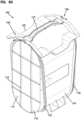
- the air cleaner 10 includes an access cover 125 to provide access to the interior region 20a of the housing body 20, such as for placement and removal of filter cartridges 100, 200.
- the access cover 125 may be a separate component or may be an integral feature of another component of the air filter cartridge 100, for example integral with the circumferential shell of the filter cartridge 100.
- the access cover 125 is integral to the air filter cartridge 100.
- the access cover 125, and thus the filter cartridge 100 are secured to the housing body 20 via a pair of connectors or lock mechanisms 90.
- the air filter cartridge 100 can be configured such that it has an axis of symmetry about a plane passing through the longitudinal axis of the air filter cartridge 100. Such a configuration can allow for the air filter cartridge 100 to be installed in either direction while still interacting in a satisfactory way with the mating parts of the housing body 20 and lock mechanisms 90.
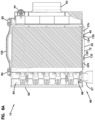
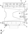
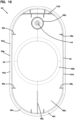
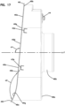
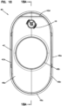
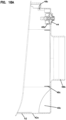
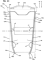
- the housing body 20 is shown in isolation. As presented, the housing body 20 is unitarily formed as a single component from a polymeric material, such as nylon, polypropylene, or ABS plastic. In one aspect, the housing body 20 extends between a first end 20a and a second end 20b and defines and interior region 20i.
- the housing body 20 can be characterized as having a central portion 22, an inlet portion 24, and an outlet portion 26. Although the terms "inlet portion” and "outlet portion” are used herein, it should be understood that, because of the configuration of the housing body 20, the inlet portion 24 can serve as the outlet end of the housing body 20 and the outlet portion 26 can serve as the inlet portion of the housing body 20.
- the central portion 22 retains the filter cartridge 100
- the inlet portion 24 secures the air inlet assembly 50 to the housing body 20 and also supports one of the lock mechanisms 90
- the outlet portion 26 secures the air outlet assembly 40 to the housing body 20 and also supports the other lock mechanism 90.
- the central portion 22 of the housing body 20 is defined by a sidewall 22a extending between a first end wall 22b proximate the inlet portion 24 and a second end wall 22c proximate the outlet portion 26.
- Each of the first and second end walls 22b, 22c respectively define openings 22d, 22e through which air can flow through the housing body 20.
- the central portion 22 further defines an access opening 22f through which the filter cartridge 100 can be installed.
- the access opening 22f is also sized such that the outlet assembly 40 and the inlet assembly 50 can be inserted through the access opening 22f during assembly of the housing assembly 12.
- the access opening 22f is provided with a grooved structure defining an open channel 22g for receiving a seal member, such as an O-ring, such that access cover 125 can be adequately sealed against the housing body 20.
- a seal member such as an O-ring
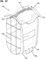
- FIGS 106 and 107 an alternative air cleaner design is shown in which the access opening 22f has a varying profile with a transversely or radially recessed portion 22f1 that can be used to enhance positive location of the filter cartridge 100 during insertion.
- the inlet portion 24 of the housing body 20 is shown as being provided with a circumferential sidewall 24a with a rectangular shape with rounded ends or corners (e.g. a race track shape). Within the sidewall 24a, a plurality of oppositely arranged and spaced apart apertures 24b are provided. The apertures 24b are for receiving cooperatively shaped latch members of the air inlet assembly 50 to facilitate a snap-fit type connection between the housing body 20 and the air inlet assembly 50.
- the inlet portion 24 is also provided with a mounting structure 24c proximate the access opening 22f.
- the mounting structure 24c provides a structure to which the lock mechanism 90 can be mounted.
- the mounting structure 24c is defined by a pair of spaced apart, parallel L-shaped channel or rib members 24d extending in a lengthwise direction of the housing body 20.
- the inlet portion 24 is further provided with a cut-out portion 24e within the sidewall 24a to facilitate mounting of a dust ejector in a desired location and orientation, as is explained later in this section.
- the outlet portion 26 of the housing body 20 is shown as being provided with a circumferential sidewall 26a with a rectangular shape with rounded ends or corners (e.g. a race track shape). Within the sidewall 26a, a plurality of oppositely arranged and spaced apart apertures 26b are provided. The apertures 26b are for receiving cooperatively shaped latch members of the air outlet assembly 40 to facilitate a snap-fit type connection between the housing body 20 and the air outlet assembly 40.
- the outlet portion 26 is also provided with a mounting structure 26c proximate the access opening 22f.
- the mounting structure 26c provides a structure to which the lock mechanism 90 can be mounted.
- the mounting structure 26c is defined by a pair of spaced apart, parallel L-shaped channel or rib members 26d extending in a lengthwise direction of the housing body 20.
- the outlet portion 26 can be further provided with a cut-out portion similar to 24e within the sidewall 26a to facilitate mounting of a dust ejector in a desired location and orientation where the air cleaner is configured for air to flow from the portion 26 to the portion 24.
- the outlet assembly 40 is shown in further detail.
- the filter cartridge 200 is not shown as being installed within the outlet assembly at Figures 14 to 18 .
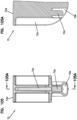
- the outlet assembly 40 includes an outlet body 42 and flow restriction indicator 44.
- the flow restriction indicator 44 is a dial-type gauge that snap-fits into the outlet assembly 40.
- the outlet body 42 is defined by a sidewall 42a extending between a first end 42b and a second end 42c.
- the sidewall 42a includes a contoured portion 42d for receiving and sealing with a portion of a seal member 204 associated with the secondary filter cartridge 200.
- the interior of the sidewall 42a forms the remaining portion of the seal interface with the secondary filter cartridge seal member 204.
- the sidewall 42a is also shown as being provided with latch portions 42e, each of which having a ramped surface 42f and a shoulder surface 42g.
- the latch portions 42e interact with the apertures 26b in the housing body 20 such that a snap-fit connection can be formed between the housing assembly 20 and the outlet assembly 40.
- the outlet assembly 40 is also shown as being provided with a flange structure 46 adjoining the first end 42b of the outlet body sidewall 42a.
- the flange structure 46 is defined by a first flange portion 46a and a second flange portion 46c that each extending radially outwardly from the sidewall 42a.
- the flange portions 46a, 46c define a mounting surface 46b on one side of the flange structure 46 and a sealing surface 46c on an opposite side of the flange structure 46.
- the sealing surface 46c of the first flange portion 46a is disposed at an angle a1 to a longitudinal axis X of the air cleaner 10 and outlet assembly 40.
- the angle a1 is an oblique or non-orthogonal angle. In the example shown, the angle a1 is 95 degrees. However, other angles are possible, such as angles ranging between 90 and 135 degrees, for example 100 degrees.
- the angle a1 is minimized such that the surface area of the sidewall 42a between the flange portions 46a, 46c is similarly minimized such that debris falling into the interior region 20i is less able to collect on the resulting ledge area of the sidewall 42a, for example when the filter cartridge 100 is being removed.
- the first and second flange portions 46a, 46c are disposed at an angle a2 with respect to each other.
- the angle a2 is greater than zero and less than 180 degrees such that the first and second flange portions 46a, 46c are disposed in a non-parallel relationship.
- the angel a2 is about 152 degrees.
- the angles a1 and a2 can also be said to be at an oblique angle to the outlet end 114.
- seal surfaces 132b, 132c of the seal member 132 can be defined by the angles a1, a2 of the flange portions 46a, 46c, the seal surfaces 132b, 132c can likewise have the angles specified above. Other angles are possible.
- the outlet assembly 40 When the outlet assembly 40 is inserted through the housing body access opening 22f such that the outlet assembly 40 resides within the interior region 20i of the housing body 20, the outlet assembly 40 can be pushed forward towards the housing body outlet portion 26 (or inlet portion 24) until the mounting surface 46b abuts the end wall 22c of the housing body 20. This position is most easily seen in the cross-sectional views of Figures 6A and 6B .
- the end wall 22c provides a positive stop against the mounting surface 46b of the first flange portion 46a.
- the ramped surface 42f of each of the latch portions 42e ride along the interior surface of the sidewall 26a until the outlet body 42 is sufficiently inserted for the latch portions 42e to be fully received into the apertures 26b.
- the shoulder surfaces 42g of the latch portions 42e lock against an edge of the apertures 26b in a snap-fit type of connection, wherein the outlet housing 42 is locked from further movement by the latch portions 42e and the end wall 22c.
- the second flange portion 46c adjoins the first flange portion 46a to form the seal surface 46d opposite the mounting surface 46b.
- the seal surface 46d provides a surface against which a correspondingly shaped seal member of the filter cartridge 100 can form a seal.
- the portion 46e of the seal surface 46d defined by the first flange portion 46a is disposed at the angle a2 to the portion 46f of the seal surface 46d defined by the second flange portion 46c. Accordingly, the seal surface 46d can be said to have a compound shape or profile.
- the seal surface 46d is curved such that a smooth transition exists.
- the first and second seal portions 46e, 46f are planar with a curved portion 46g connecting the portions 46e, 46f.
- all or part of the seal surface 46d is curved rather than being planar.
- either or both of the first and second seal portions 46e, 46f can be curved rather than being planar.
- the first seal portion 46e represents less than half of the total seal surface 46d, and thus has a lesser length than that of the second seal portion 46f.
- the outlet assembly 40 is also provided with an outlet end 48 defined by an end wall 48a and an outlet tube 48b to which a hose or duct can be connected.
- the outlet end 48 is also shown as including internal sidewalls or ribs 48c for interacting with the filter cartridge 200.
- the outlet end 48 is further shown as also including a sidewall or well 48d for receiving the restriction indicator 44.
- outlet assemblies 40 can be mounted onto the housing body 20 to suit any particular application.
- the outlet assembly could be provided with a differently sized or shaped outlet tube or duct, could be provided without a restriction indicator, or could be provided with additional ports for the installation of electronic sensors. Accordingly, the disclosure is not necessarily limited to the specific outlet assembly configuration described herein as other or different features may be included.
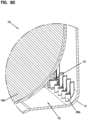
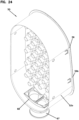
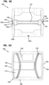
- the inlet assembly 50 includes an inlet body 52, a precleaner assembly 60, and a dust ejection assembly 66.
- the precleaner assembly 60 generally is used to clean selected material or contaminants carried by an air stream into the air cleaner assembly 10 before the air reaches the filter cartridge 100 positioned therein.
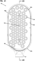
- the precleaner 60 generally includes a sidewall 62a bounding an end wall 62b through which a plurality of cyclonic separator tubes 64 extend. In the embodiment shown in the drawings, 42 separator tubes 64 are provided. More or fewer separator tubes 64 can be provided.
- the inlet body 52 is also shown as including a sidewall 52a bounding an end wall 52b.
- a plurality of receptacles 54 are shown as being provided on and extending through the end wall 52b.
- the receptacles 54 are received into the outlets of the separator tubes 64 when the precleaner assembly 60 is installed into the inlet body 52, wherein the sidewall 62a slides within the sidewall 52a.
- the precleaner assembly 60 can be secured via a fastener 62c (e.g. a threaded screw or bolt) extending into a threaded opening 52c in the end wall 52b of the inlet body 52.
- contaminants are separated to the outside walls of the separator tubes 64 and are collected within the interior space defined between end walls 62b, 52b and the sidewall 52a and are then ejected out of the dust ejection port assembly 66.
- the relatively contaminant free air passing through the central portions of the separator tubes 64 is received by the receptacles 54 where the air can pass through the end wall 52b and into the interior region 20i where the air can be received by the filter cartridge 100 for further cleaning.
- the dust ejection assembly including a dust ejection port 67 mounted through an opening in the inlet body sidewall 52a and a retaining clip 68 securing the dust ejection port 67 to the sidewall 52a.
- the dust ejection assembly 66 disclosed herein is removable and can be mounted in multiple locations, where the air cleaner 10 is provided with multiple openings 52d.
- the inlet assembly 50 is installed through the access opening 22f of the housing body 20 in a manner similar to that already described for the inlet assembly 40.
- the removability of the dust ejection assembly 66 facilitates this assembly process, as insufficient clearance would result if the dust ejection port 67 were non-removable and assembly through the access opening 22f were attempted.
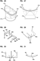
- the dust ejection port 67 is defined by a tubular sidewall 67a that extends to a flange 67b.
- the flange 67b acts as a stop to prevent further insertion into the interior.
- the flange 67b is provided with a complementary shape to the profile of the sidewall 52a such that a generally flush fit arrangement between the flange 67b and the sidewall 52a exists.
- both the sidewall 52a, at the location of opening 52d, and the flange 67b are curved.
- the flange 67b can be planar or flat.
- the dust ejection port 67 is further provided with a pair of retaining flanges or ears 67c that pass through the inlet body opening 52d when the flange 67b is abutted with the sidewall 52a.
- the retaining flanges 67b are received by the retaining clip 68 which includes a sidewall 68a defining an opening 68b with a narrowed opening area 68c for receiving a narrowed neck region of the tubular sidewall 67a between the flanges 67b, 67c of the dust ejection port 67.
- the narrowed opening area 68c enables for a snap-fit type attachment between the dust ejection port 67 and the retaining clip 68.
- the retaining clip 68 is inserted onto the ejection port sidewall 67a on the side of the inlet body sidewall 52a opposite of the flange 67b (i.e. on the interior side of sidewall 52a). Once inserted, the retaining clip 68 operates against the retaining flanges 67b to prevent the dust ejection port 67 from being removed from the inlet body 52. As indicated at Figures 28 , the clip 68 has a width w1 at the distal end of the clip which increases to a width w2 towards the opposite end of the clip 68 to form a ramp-like structure.
- the increasing thickness of the clip 68 acts to bind the ejection port 67 in place such that the ejection port 67 is axially secured in place with respect to the sidewall 52a.
- a handle or lip member 68d is provided on the retaining clip 68 to facilitate manipulation of the retaining clip during insertion and removal.
- Ramped sidewall members or ribs 68e can also be provided to interact with the ends of the retaining flanges 67c to prevent rotation of the ejection port 67 with respect to the sidewall 52a. Preventing rotation is advantageous as loosening of the connection between the retaining clip 68 and the ejection port 67 could occur with such rotation.
- the retaining clip sidewall 68a is provided with a complementary shape to the profile of the sidewall 52a such that a generally flush fit arrangement between the sidewall 68a and the sidewall 52a exists.
- both the sidewall 52a, at the location of opening 52d, and the sidewall 68a are curved.
- the sidewall 68a can be planar or flat.
- the sidewall 52a of the inlet body 52 is also shown as being provided with latch portions 52e, each of which having a ramped surface 52f and a shoulder surface 52g.
- the latch portions 52e interact with the apertures 24b in the housing body 20 such that a snap-fit connection can be formed between the housing assembly 20 and the inlet assembly 50.
- the inlet assembly 50 is also shown as being provided with a flange structure 56 adjoining the second end 42c of the outlet body sidewall 42a.
- the flange structure 56 is defined by a first flange portion 56a and a second flange portion 56c that extend radially outwardly from the sidewall 52a.
- the flange portions 56a, 56c define a mounting surface 56b on one side of the flange structure 56 and a sealing surface 56c on the opposite side of the flange structure 56.
- the first flange portion 56a is disposed at an angle a3 to a longitudinal axis X of the air cleaner 10 and inlet assembly 50.
- the angle a3 is an oblique or non-orthogonal angle.
- the angle a1 is 5 degrees.
- other angles are possible, such as angles ranging between 0 and 45 degrees, for example 10 degrees.
- the first and second flange portions 56a, 56c are disposed at an angle a4 with respect to each other.
- the angle a4 is greater than zero and less than 180 degrees such that the first and second flange portions 56a, 56c are disposed in a non-parallel relationship.
- the angel a4 is about 152 degrees. Other angles are possible.
- the inlet assembly 50 can be pushed forward towards the housing body inlet portion 24 (or inlet portion) until the mounting surface 56b abuts the end wall 22b of the housing body 20.
- the end wall 22b provides a positive stop against the mounting surface 56b of the first flange portion 56a.
- the ramped surface 52f of each of the latch portions 52e ride along the interior surface of the sidewall 24a until the inlet body 52 is sufficiently inserted for the latch portions 52e to be fully received into the apertures 24b.
- the shoulder surfaces 52g of the latch portions 52e lock against an edge of the apertures 24b in a snap-fit type of connection, wherein the inlet housing 52 is locked from further movement by the latch portions 52e and the end wall 22b.
- the flange structure 56 adjoins the first flange portion 56a to form the seal surface 56d opposite the mounting surface 56b.
- the seal surface 56d provides an axial surface against which a correspondingly shaped seal member of the filter cartridge 100 can form a seal.
- the seal surfaces of the seal members can have the same shape or profile as explained below for the seal surfaces herein.
- the portion 56e of the seal surface 46d defined by the first flange portion 56a is disposed at the angle a4 to the portion 56f of the seal surface 56d defined by the second flange portion 56c.
- the seal surface 56d can be said to have a compound shape or profile.
- the seal surface 56d is curved such that a smooth transition exists.
- the first and second seal portions 56e, 56f are planar with a curved portion 56g connecting the portions 56e, 56f.
- all or part of the seal surface 56d is curved rather than being planar.
- either or both of the first and second seal portions 56e, 56f can be curved rather than being planar.
- the first seal portion 56e represents less than half of the total seal surface 56d, and thus has a lesser length than that of the second seal portion 56f.
- inlet assemblies 50 can be mounted onto the housing body 20 to suit any particular application.
- an inlet assembly 50 with no precleaner, an inlet duct, a different precleaner design, and/or dust ejection assembly could be provided. Accordingly, the disclosure is not necessarily limited to the specific inlet assembly configuration described herein as other or different features may be included.
- the filter cartridge 100 extends between a first end 102 and a second end 104.
- the first end 102 can be characterized as the upstream end of the filter cartridge 100 while the second end 104 can be characterized as the downstream end of the filter cartridge 100.
- the filter cartridge 100 can be considered to be the main or primary filter cartridge, and is used to selectively separate a desired amount of particulate or containment material.
- Filter cartridge 100 is generally a service part or removable component, such that it is periodically removable and replaceable as desired or necessary during the lifetime of the air cleaner 10.
- the access cover 125 is unlocked from the housing 20, and the occluded filter 100 is removed by pulling the access cover in a direction R1 away from the housing 20 via a handle 127 associated with the access cover 125.
- another filter 100 can be placed in the housing 20 by inserting the filter cartridge 100 in an insertion direction I1.
- the directions I1 and R1 are orthogonal to the longitudinal axes X, X1 of the filter cartridge 100 and housing 20.
- the access cover 125 is integral to the filter cartridge 100 and thus serves as the previously described access cover 125.
- the handle 127 is integrally formed with the access cover 125.
- the handle 127 has a length that is a majority of the length of the media pack 110.
- Figures 106 and 107 show the filter cartridge 100 that the access opening 22f can have a varying profile with a recessed portion 22f1.
- the access cover 125 can be formed with a complementary shape to the access opening 22f such that the access cover 125 has a contoured shape with a protruding portion 125a that mates or abuts with the recessed portion 22f1
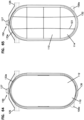
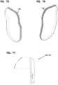
- the filter cartridge 100 generally includes a media pack 110, a shell 120 integrally including the access cover 125 and the handle 127, a first sealing member 130 at the inlet end of the media pack 110, and a second sealing member 132 at the outlet end of the media pack 110.
- the sealing members 130, 132 will generally be made of a relatively flexible material and may be referred to herein as a "flexible sealing member,” and can include an axial or radial sealing member.
- the sealing members 130, 132 are provided as injection molded gaskets.
- the sealing members 130, 132 are provided as gaskets with alternating segments of parallel lip seals 134 and open-faced pocket structures 136, as is described later in this section.
- the seal members 130, 132 are shown in isolation at Figures 75-77 .
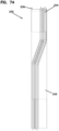
- the media pack 110 has inlet flow face 112 for receiving unfiltered air or pre-cleaned air from the precleaner (if provided) and an outlet flow face 114 for delivering filtered air.
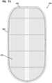
- the media pack 110 is shown in isolation at Figure 70 .
- the media pack 110 has an obround cross-sectional shape. However, other shapes are possible, such as round, oval, and rectangular cross-sectional shapes.
- the media pack 110 defines an outer perimeter 116 extending between the inlet and outlet flow faces 112, 114.
- the media pack 110 is formed from a coiled media construction, for example a media construction having a fluted (typically corrugated) media sheet and a facing media sheet that together define parallel flutes to form a fluted or z-filter media construction.
- a coiled media construction for example a media construction having a fluted (typically corrugated) media sheet and a facing media sheet that together define parallel flutes to form a fluted or z-filter media construction.
- Suitable media constructions for the media pack 110 are discussed in more detail in the Media Types and Configurations section.
- the shell 120 of the filter cartridge 100 is formed from a polymeric material, such as nylon, polypropylene, or ABS plastic.
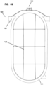
- the shell 120 is shown in isolation at Figures 66-69 .
- the shell 120 defines a perimeter wall 122 that surrounds the outer perimeter 116 of the media pack 110.
- a grid structure 123 is also shown as being provided with the shell 120 for supporting the outlet flow face 114 of the media pack 110.
- the shell 120 may be secured to the media pack 110 by an adhesive.
- the perimeter wall 122 may surround the entirety of the media pack outer perimeter 116, as shown, or surround a portion of the media pack outer perimeter 116.
- the access cover 125 and handle 127 are integrally formed with the shell.
- the access cover 125 includes a main body 125a that is sized and shaped to mate against and cover the access opening 22f of the housing body 20.
- the main body 125a defines a sealing surface 125b against which a seal associated with the housing body 20 can form a seal.
- the handle 127 is formed with the access cover 125 such that an open space 127a exists between the handle 127 and the cover 125 to allow an operator to grasp the handle 127.
- the open space 127a can be defined as a recess beneath one or both sides of the handle 127 or can be a completely open space, as shown in the drawings.
- the access cover 125 can be provided with indicia 125c, such as text and directional arrows, to provide an indication to an operator as to the proper installation orientation of the filter cartridge 100.
- first and second seal support flanges 124, 126 extend orthogonally from the perimeter wall 122.
- the seal support flanges 124, 126 respectively provide a support surface for the seal members 130, 132.
- the seal support flanges 124, 126, and thus the supported seal members 130, 132, are respectively provided with profiles complementary to the sealing outlet assembly sealing surface 46d and the inlet assembly sealing surface 56d.
- the seal support flange 124 defines a support surface 124a having a first portion 124b disposed at angle a4 and an adjoining second portion 124c, wherein the first and second portions 124b, 124c form the angle a4 between them.
- the shape of the support flange 124 imparts similar features onto the seal member 130 such that a seal surface 130a of the seal member 130 has a first portion 130b at the angle a3 and an adjoining second portion 130c at the angle a4 with respect to the first portion 130b.
- the media pack inlet flow face 112 is shown as being orthogonal to the longitudinal axis X1 of the filter cartridge 100. Accordingly, the support flange first portion 124a and the seal first portion 130b can be said to form an angle a5 with the plane P1 defining the inlet flow face that is equal to the angle a3 minus 90 degrees. As such, the angle a5 in the example shown is 10 degrees.
- the seal support flange 126 defines a support surface 126a having a first portion 126b disposed at the angle a1 and an adjoining second portion 124c disposed at the angle a2 with respect to the first portion 126b.
- the shape of the support flange 126 imparts similar features onto the seal member 132 such that a seal surface 132a of the seal member 132 has a first portion 132b at the angle a1 and an adjoining second portion 132c at the angle a2 with respect to the first portion 132b.
- the media pack outlet flow face 114 is shown as being orthogonal to the longitudinal axis X1 of the filter cartridge 100.
- the support flange first portion 126a and the seal first portion 132b can be said to form an angle a6 with the plane P2 defining the inlet flow face that is equal to the angle a1 minus 90 degrees.
- the angle a6 in the example shown is 10 degrees.
- the seal surfaces 130a, 132a can be characterized as defining axial seal surfaces or axially facing seal surfaces as the face of the seal surface is more orthogonal than not to the longitudinal axis X1 (i.e. more parallel than not to the end faces of the media pack 110 or facing in the same general direction as the media pack end) of the filter cartridge 100.
- the seal members 130, 132 can be provided with various features to enhance sealing.
- the seal members 130, 132 are shown in isolation at Figures 61A-61C , respectively.
- Figure 61B a cross-sectional view of the seal members 130, 132 is presented.
- the seal members 130, 132 are injection molded seals.
- the seal members 130, 132 include a base member 133a and a pair of seal lips or extensions 133b, 133c that together form a c-channel type shape.
- the base member 133a and the side 133d of the lip extension 133b interfaces with the seal support flanges 124, 126 and can be secured to the flanges 124, 126 via an adhesive.
- the seal members 130, 132 can also include a top segment 133e wherein the c-shaped channel is oriented 90 degrees to the remainder of the seal member 130, 132.
- the open side of the channel faces in the same direction as the lip extension 133c of the remaining segment of the seal member 130, 132.
- This configuration allows for the seal members 130, 132 to be more easily molded onto the inlet and outlet housing assemblies 40, 50.
- the distal ends of each of the lip extensions 133b, 133c form the axial seal surface for the seal members 130, 132.
- the seal surface first portions 130b, 132b form an angle with each as defined by the angles a1 and a3. As shown, this angle is about 20 degrees. In one aspect, the seal surface second portions 130c, 132c form an angle with each other as defined by the angles a1, a2, a3, and a4. As shown, this angle is about 65 degrees. Other angles are possible. In some examples, the first portions 130b, 132b are planar while in others the first portions 130b, 132b are curved. In some examples, the second portions 130c, 132c are planar while in others the second portions 130c, 132c are curved.
- each of the first portions 130b, 132b and the second portions 130c, 132c are planar with a curved or radiused portion joining the first and second portions together. In some examples, the first portions 130b, 132b are planar and the second portions 130c, 132c are curved. In some examples, the first portions 130b, 132b define a majority of the length of the seal surfaces and the second portions 130c, 132c define a minority of the length of the seal surfaces.
- the seal members 130, 132 being disposed at the angles a5, a6, the seal members 130, 132 taper towards each other in the insertion direction I1 and in a direction away from the cover 125 such that the seal members 130, 132 are closer to each other at a location remote from the cover 125 as compared to a location proximate the cover 125 (i.e. distance between seal members 130, 132 increases in a direction towards the cover).
- This tapered configuration allows for easier installation of the filter cartridge 100 into the interior region 20i of the housing body 20 with less compressive resistance from the seal members 130, 132, as compared to a configuration where the seal members 130, 132 oriented entirely parallel to each other and the plane P without any tapering.
- Another advantage of the disclosed configuration is that the filter cartridge seals against the inlet and outlet housing assemblies 40, 50 rather than the housing body 20. Because the seal member 130 forms a seal against the seal surface 56d of the inlet housing assembly 50 and the seal member 132 forms a seal against the seal surface 46d of the outlet housing assembly 40, it is not necessary for the cover 125 to form a leak-proof seal with the housing body 20 or for the filter cartridge 100 to form a leak-proof seal with the housing body 20.
- the filter cartridge 100 is also shown as being provided with lock interface features 150 at each end.
- the lock interface features 150 interact with the locking mechanisms 90 such that the filter cartridge 100 can be locked in place with respect to the housing 20.
- the lock interface features 150 include an arcuate rib structure 152 and a pair of tab structures 154, each of which is integrally formed on the access cover 125. The structure and function of these features are further described in the lock mechanism section.
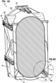
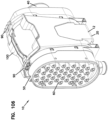
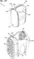
- the exemplary air cleaner assembly 10 includes an optional secondary or safety filter cartridge 200.
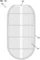
- the safety filter cartridge 200 is shown in isolation at Figures 71 to 74 .
- the safety filter 200 is generally positionable between the main filter cartridge 100 and the outlet 48b of the housing 20.
- the safely filter 200 is removably positioned within the air cleaner assembly 10 and would also typically be considered to be a service component that is removable and replaceable, as desired and/or necessary.
- the exemplary embodiment of safety filter 200 includes an outer frame 202 that carries a seal member 204 having a pair of parallel lip seals, and generally matches the size and shape of the inner area of the housing outlet body 42 (e.g. straight segmented portions 42d together with the straight sides of the interior surface of the sidewall 42a) and can seal to the outlet body 42, preferably with no gaps. In this way, the safety filter 200 can be pressed into the housing with a friction fit against the wall of the housing so that no air can reach the outlet without first going through the safety filter.
- the safety filter 200 can also include filtration media 220, such as pleated media.
- a handle 206 may also be provided to aid in installing and removing the filter cartridge 200 from the housing 20 via the access opening 22f.
- filter media can be used as the media pack for the filter cartridges 100, 200 in accordance with embodiments of the invention.
- woven and non-woven materials using natural and/or synthetic fibers can be used to form fluted filter media, pleated media, and depth media.
- An exemplary configuration includes fluted filter media, such as a z-filter construction.
- the term "z- filter construction" as used herein, is meant to refer to a type of filter construction in which individual ones of corrugated, folded or otherwise formed filter flutes are used to define sets of longitudinal, typically parallel, inlet and outlet filter flutes for fluid flow through the media; the fluid flowing along the length of the flutes between opposite inlet and outlet flow ends (or flow faces) of the media.
- One type of z-filter media utilizes two specific media components joined together to form the media construction.
- the two components include a fluted (typically corrugated) media sheet and a facing media sheet.
- the facing media sheet is typically non-corrugated, although it is possible for it to also be corrugated (e.g., perpendicular to the flute direction) as described in U.S. Provisional Application No. 60/543,804, filed February 11, 2004 , and published as PCT WO 05/077487 on August 25, 2005 .
- the fluted media sheet and the facing media sheet are used together to define media having parallel inlet and outlet flutes.
- the fluted sheet and facing sheet are secured together and are then coiled as a media strip to form a z-filter media construction.
- Such arrangements are described, for example, in U.S. Patent Nos. 6,235,195 and 6,179,890 .
- some non-coiled sections or strips of fluted (typically corrugated) media secured to facing media are stacked with one another, to create a filter construction.
- Corrugated media is a specific form of fluted media, wherein fluted media has individual flutes or ridges (for example formed by corrugating or folding) extending thereacross.
- corrugated is used herein to refer to structure in media, such as media having a flute structure resulting from passing the media between two corrugation rollers (e.g., into a nip or bite between two rollers, each of which has surface features appropriate to cause corrugations in the resulting media).
- Serviceable filter element or filter cartridge configurations utilizing z-filter media are sometimes referred to as "straight through flow configurations" or by variants thereof.
- serviceable filter elements or cartridges have an inlet flow end (or face) and an opposite exit flow end (or face), with flow entering and exiting the filter cartridge in generally the same straight through direction.
- the term "serviceable” in this context is meant to refer to a media containing filter cartridge that is periodically removed and replaced from a corresponding fluid (e.g. air) cleaner.
- the connectors 90 hereafter referred to as lock mechanisms 90, are provided at each end of the filter cartridge 100.
- the filter cartridge 100 includes features 150 including arcuate ribs 152 and tab structures 154 that are integrally formed with the access cover 125 of the shell 120.
- Each of the tabs 154 is received in a corresponding recess 92a of an operator part 92 of the lock mechanism 90.
- the filter cartridge 100 cannot be fully inserted into the housing 20 unless the lock mechanisms 90 are rotated into a fully unlocked position such that the recesses 92a align with the tabs 154.
- the operator part 92 is shown in further detail.
- the operator part 92 includes the aforementioned recess 92a, a pair of handle portions 92b for enabling a user to grasp and rotate the operator part 92, a cover portion 92c, a stem portion 92d extending from the cover portion 92c, a retaining groove 92e defined within the stem portion 92d, an arc-shaped rib portion 92f defining a groove or channel 92g between the rib portion 92f and a sidewall portion 92h of the cover portion 92c, a pair of recessed areas 92i at the location where the rib portion 92f meets the sidewall portion 92h, and a central indexing member 92j extending between the rib portion 92f and the sidewall portion 92h.
- the sidewall portion 92h is also shown as including lead in or ramped portions 92h at the ends of the of the sidewall portion 92h to better allow the cover portion
- the base part 94 includes a main body 94a within which a central aperture 94b is defined, a lock spring retaining feature 94c including a pair of apertures 94f a pair of apertures 94g and a central tab 94h, a pair of arc-shaped rib portions 94d, and a pair of attachment features 94e for securing the lock mechanism 90 to the housing 20.
- the attachment features 94e include a pair of L-shaped channels 94e that receive the correspondingly shaped L-shaped rib members 24d, 26d on the housing body 20.
- a lock spring 96 of the lock mechanism 90 is shown in further detail.
- the lock spring 96 extends from a base portion 96a to ramped portions 96b which in turn extends to tab portions 96c.
- the lock spring 96 further includes a latch portion 96d projecting from the tab portion 96c.
- the latch portion 96d includes a latch face 96e for engaging against an edge 92m of the cover portion 92.
- the lock spring 96 is also shown as being formed with tabs 96e and 96f for securing the lock spring 96 to the lock spring retaining feature 94c of the base part 94.
- the lock spring 96 is cut from a steel sheet (e.g. spring steel) and bent to shape.
- the retaining ring 98 includes a main body 98a within which a central aperture 98b is defined.
- the retaining ring 92 is formed from a metal material, such as spring steel.
- the lock spring base portion 94a is received within the lock spring retaining feature 94c such the tabs 96e extend through openings 94f and 94g and the tab 96f is retained by the central tab 94h of the base part 94and such that the ramped portions 96b extend away from the base part main body 94a.
- Figure 36 shows the lock spring 96 attached to the base portion 94 with the cover 92 removed to better show the connection between the lock spring 96 and the base portion 94. This configuration allows the lock spring tab portion 96c to be deflectable from a relaxed or resting position (i.e. the raised position in the drawings), as shown at position P1 in Figures 6E and 32-36 , to a deflected position (i.e.
- the operator part 92 is mounted to the base part 94 by passing the stem portion 92d of the operator part 92 through the central aperture 94b of the base part 94 such that the operator part cover portion 92c covers the base part main body 94a.
- the ribbed portion 94d of the base part 94 rests in a groove formed between the operator part ribbed and outer wall 92h.
- the two parts are secured together by installing the retaining ring 98 onto the retaining groove 92e.
- the operator part 92 is rotatable with respect to the base part 94 from an unlocked position to a locked position.
- the operator part 92 In the unlocked position, the operator part 92 is aligned such that the tab portion 96c extends into the recess 92a in the cover portion 92c of the operator part 92 and such that the latch face 96f of the locking spring 96 rests against the side edge 92m of the operator part 92. Due to the interaction between the latch face 96f and the operator part side edge 92m, the operator part 92 is unable to be rotated out of the unlocked position with the locking spring 96 in the resting position.
- the operator part 92 can be easily rotated back to the unlocked position as the ramped face 96e will allow the locking spring latch portion 96d to easily deflect and slide past the side edge 92f on the operator part 92.
- each latch portion 96d is displaced beyond the side edge 92f thereby allowing the operator part 92 to be rotated towards the locked position in either a clockwise or counterclockwise direction.
- the ribbed portion 92f on the operator part 92 slides along the ribbed structure 152 of the filter cartridge 100.
- the ribbed structure 152 which can be characterized as a connection member, works in conjunction with the operator part 92 to secure the media pack within the air cleaner housing.
- the filter cartridge 100 is a true side-loaded filter cartridge which does not need to be axially displaced after insertion into the housing 20 to effectuate a seal
- the filter cartridge 100 is configured such that at least a portion of the ribbed structure 152 extends axially beyond the inlet/outlet flow end of the media pack 110.
- the entirety of the ribbed structure 152 is axially beyond the inlet/outlet flow end of the media pack 110.
- the locking mechanisms 90 do not directly effectuate a seal at seal members 130, 132 in the direction of the longitudinal axis X. Instead, the seal is formed by an interference fit between the individual seals members 130, 132 and the individual sealing surfaces 46d, 56d.
- the lock mechanisms 90 can be configured to exert a compressive force onto the filter cartridge 100 and thus the seal members 130, 132 in the insertion direction.
- the locking mechanisms 90 do operate to lock the filter cartridge 100 in place in self centering fashion wherein stress is transferred between the lock mechanisms 90 and cover 125 but without imparting a force onto the seal members 130, 132.
- the lock mechanisms 90 will still function to axially align and fix the filter cartridge 100 to effectuate a single seal without the need for the presence of the second seal or any other component on the cartridge or housing to effectuate the seal.
- the retaining ring 92 is configured such to exert a spring force onto the operator part 92.
- the operator part 92 is rotated into the locking position until the rib 92j of the operator part engages with a stop member or detent 152i on the arcuate shaped rib structure 152 on the filter cartridge 100 to aid in retaining the operator part 92 in the locked position and to provide an installer with tactile feedback of the locked position.
- the rib 92j rides on to of or against the rib structure 152 on the filter cartridge 100 which provides slight resistance to rotation.
- the rib 92i Once the rib 92i reaches the stop member 152i, the rib 92i snaps into the recess defined by the stop member 152i, thus simultaneously indexing the operator part 92 into the locked position and providing tactile feedback. To remove the filter cartridge 100 from the housing, the operator simply rotates each operator part 92 until the recesses 92a align with the tabs 154.
- the complementary configuration of the locking mechanisms 90 and filter cartridge tabs 154 ensures that the correct filter cartridge is installed into a housing that is actually designed to receive the filter cartridge. If an attempt is made to install a filter cartridge that does not include the tabs 154, the filter cartridge 100 will fail to enable the lock mechanisms to move to the locked position, thus alerting the installer that an incorrect filter cartridge is installed.
- the tabs and recesses are shown as having a particular shape, other shapes are possible. Different shapes may be used for different air cleaner sizes or designs, thus ensuring the correct filter cartridges are installed appropriate housings throughout an entire product line.
- the mounting arrangement 30 is shown as being installed on the main housing body 20 at Figures 1 and 3-8 .
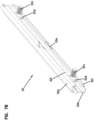
- the mounting arrangement 30 is shown as including a pair of mounting structures 32 that are mounted to the housing body 20 in a spaced apart and parallel arrangement.
- the mounting arrangement 30 is also shown as including four mounting clips 34. Either of the mounting clips 34 or the mounting structures 32 can be independently used to mount the air cleaner 10 to a supporting structure with the mounting clips 34 providing a fixed-distance mounting arrangement and the mounting structures providing an adjustable mounting system. Where both mounting structures 32 and mounting clips 34 are provided, an installer or designer can utilize whichever mounting approach best suits a particular application.
- an air cleaner 10 can be provided with only the mounting structures 32 or only the mounting clips 34.
- the housing body 20 defines a pair of channels 25 defined by sidewalls 25a which receive the mounting structures 32.
- the housing body 20 is also provided with end walls 25b extending across the sidewalls 25a at each end.
- the end walls 25b are shown as including apertures 25c such that the end walls can receive mounting clips 34.
- the mounting clips 34 form a portion of the mounting arrangement.
- the housing body 20 is also shown as including apertures 25d for receiving a portion of the mounting structures 32 such that the mounting structures 32 can be secured to the housing body 20.
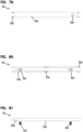
- each mounting structure 32 includes a first channel part 32a that receives a second channel part 32b.
- the second channel part 32b has a width or dimension that matches the head 32d of a bolt 32c that allows the bolt to slide along the length of the second channel part 32b but prevents the bolt from rotating.
- the first channel part 32a has a central opening 32e through which the head 32d can pass such that the head can be received by the second channel part 32b.
- the first channel part 32a additionally has lateral walls 32f that extend towards each other to secure the opposite side of the bolt head 32d.
- a bolt 32c can be received into the first channel part 32a and then into the second channel part 32b such that the bolt 32c is slidably secured between the second channel part 32b and the walls 32f.
- the position of the bolts 32c can be easily adjusted to align with a given mounting structure.
- the bolts 32c are prevented from sliding off either end of the channel parts 32a, 32b by the end walls 25b on the housing body 20.
- the second channel part 32b is shown as including an extension part 32g at one end that is received by the housing body slots 25d and an extension part 32h at the other end that can engage with or interact with the mounting clip 34.
- the mounting structure 32 can also be provided with a spacer, fill, or interfence member 32k (e.g. collapsed polymeric tube or moon-shaped polymeric tube) that can be received by the first and second channel parts 32a, 32b that can aid in holding the bolts 32c in a fixed position and dampen potential vibration.
- the first channel part 32a can be provided with apertures 32f that receive tabs 32g of the second channel part 32b to aid in securing the first and second channel parts 32a, 32b together.
- the retaining clip 34 includes a base portion 34a, a head portion 34b extending from the base portion 34a, and a clip portion 34c extending from the base portion 34a.
- the head portion 34b includes an aperture 34d, which can be a threaded opening for receiving a mounting bolt.
- the mounting clip 34 is installed onto the end wall 25b such that the head portion 34b extends through the aperture 25c and such that the end wall 25b is clipped between the base portion 34a and the clip portion 34c.
- the retaining clip 34 is further provided with a snap member 34e that snaps into the recess 25c when the clip 34 is installed such that the clip 34 is retained onto the end wall 25b via a snap-fit type connection.
- the clip member 34 can also be provided with protrusions 34f that can snap into recesses formed in the housing body 20 to further secure the clip member 34.
- the air cleaner 10 is provided with a positioning arrangement 70 disposed within a well area 27 of the housing body 20.
- the well area 27 is defined by a pair of sidewall portions 27a and a sidewall portion 27b.
- the portions 27a, 27b are a part of the housing body sidewall 22a.
- the positioning arrangement 70 is designed to ensure that a proper filter cartridge 100 is installed into the air cleaner 10.
- the positioning arrangement creates an internal profile within the housing body 20 that requires the filter cartridge 100 to have a matching and complementarily shaped profile in order to be received fully into the housing body 20.
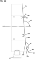
- the positioning arrangement 70 is formed by a pair of arrays with spaced apart ribs 29b extending from the housing body sidewall 22a to pin extensions 29a.
- five pins 29a and ribs 29b are shown on each side of the housing body interior region 20i.
- the pins 29a and ribs 29b are each configured to receive and retain an insert module 72.
- three insert modules 72 are mounted onto the pins 29a and ribs 29b on each side of the housing body 20.
- the positioning arrangement 70 is modular in nature and thus can be customized to achieve a number of different internal profiles to fit a particular application. For example, one, two, four, or all five insert modules 72 could be installed on each side.
- the spacing between the insert modules 72 can likewise be customized (e.g. spaced on every other pin 29a, etc.).
- the number and arrangement of the insert modules 72 can be different from one side of the housing body 20 to the other.
- the filter cartridge 100 can then be designed such that no part of the filter cartridge interferes with the insert modules 72.
- An asymmetrical arrangement (side-to-side or front-to-back) can be selected such that it is impossible to inadvertently insert the filter cartridge 100 in the reverse direction, thus ensuring that even a properly selected filter is properly installed.
- an example filter cartridge 100 profile portion or extension 100a is shown in which portions of the filter cartridge profile 100a extend between the open spaces defined between the insert modules 72 and in which no portion of the filter cartridge profile 100a extends into a space occupied by an insert module 72.
- a filter cartridge 100 must have a profile generally corresponding to profile 100a in order to be fully received within the interior region 20i of the housing body 20 in the proper orientation.
- the profile extension 100a is a protrusion integrally formed with the filter cartridge shell 120.
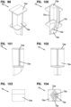
- Figures 99-105a show an example insert module 72 which includes a main body 72a a recess 72b for receiving the pin 29a and a recess 72c for receiving the rib 29b.
- the insert module 72b is also shown as including a profile head 72d which can act as an interference surface for an improperly selected and/or installed filter cartridge 100.
- the insert module 72 can also be provided with a pin structure 72e disposed within the recess 72b that can be received by a corresponding opening 27c in the pins 29b.
Description
- The present invention relates to filter arrangements, typically for use in filtering air, such as intake air for internal combustion engines, and more particularly relates to filter assemblies that include multiple components arranged in a housing to provide desired filtering capabilities.
- Air or other gas filtering is desirable in a number of systems. A typical application is in the filtration of intake air to internal combustion engines. Another is in the filtration of crankcase ventilation filter assemblies. Typically, such systems comprise filter assemblies having a serviceable filter cartridge therein. After a period of use, filter media within a filter housing requires servicing, either through cleaning or complete replacement. Typically, for an air cleaner or crankcase ventilation filter assembly used with an internal combustion engine, for example, on a vehicle, the filter media is contained in a removable and replaceable, i.e. serviceable, component, typically referred as a filter element or cartridge. The filter cartridge is configured to be removably sealed within the air cleaner, in use. Improvements in filter arrangements relating to assembly, serviceability, and/or use are desirable. The filter cartridge can be provided as a first (e.g., primary) filter cartridge or a second (e.g., secondary or safety) filter cartridge. The air cleaner assembly can contain only a first filter cartridge or both a first filter cartridge and a second filter cartridge.
- Known side-load air filter cartridges are for example disclosed in
JP H11 132117 A DE 10 2014 012490 A1 . - A side-load air filter cartridge according to the present invention is defined by
independent claim 1. An air cleaner assembly is disclosed. In one aspect, the air cleaner assembly includes a housing defining an inlet and an outlet, and including an access opening between the inlet and outlet. The air cleaner also includes a filter cartridge received within the housing and covering the access opening. The air cleaner also includes a lock mechanism. The lock mechanism is movable between an unlocked position in which the filter cartridge can be installed and removed from the housing and a locked position in which the filter cartridge is secured within the housing. The filter cartridge and lock mechanism include interacting features allowing the lock mechanism to be moved from the unlocked position to the locked position only when the filter cartridge is installed within the housing. - The present invention will be further explained with reference to the appended Figures, wherein like structure is referred to by like numerals throughout the several views, and wherein;
-
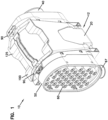
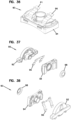
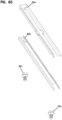
Figure 1 is a first perspective view of an air cleaner in accordance with an embodiment of the invention. -
Figure 1A is a perspective view of the air cleaner shown inFigure 1 , with a primary filter cartridge shown as being removed from the housing. -
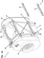
Figure 1B is a perspective view of the air cleaner shown inFigure 1 , with a mounting structure of a mounting arrangement shown as being removed from the housing. -
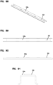
Figure 2 is a second perspective view of the air cleaner shown inFig. 1 . -
Figure 3 is a side view of the air cleaner shown inFigure 1 . -
Figure 3A is a cross-sectional view of the air cleaner shown inFigure 1 , taken along theline 3A-3A inFigure 3 . -
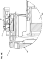
Figure 3B is an enlarged view of a portion of the air cleaner shown inFigure 3A . -
Figure 4 is an inlet end view of the air cleaner shown inFigure 1 . -
Figure 5 is an outlet end view of the air cleaner shown inFigure 1 . -
Figure 6 is a top view of the air cleaner shown inFigure 1 . -
Figure 6A is a cross-sectional view of the air cleaner shown inFigure 1 , taken along theline 6A-6A inFigure 6 . -
Figure 6B is a cross-sectional view of the air cleaner shown inFigure 6A with the filter cartridges removed from the air cleaner. -
Figure 6C is a cross-sectional view of the air cleaner shown inFigure 1 , taken along theline 6C-6C inFigure 6 . -
Figure 6D is an enlarged view of a portion of the air cleaner shown inFigure 6C . -
Figure 6E is a cross-sectional view of the air cleaner shown inFigure 1 , taken along theline 6E-6E inFigure 6 . -
Figure 7 is a bottom view of the air cleaner shown inFigure 1 . -
Figure 8 is an exploded perspective view of the air cleaner shown inFigure 1 . -
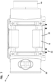
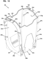
Figure 9 is a first perspective view of the housing of the air cleaner shown inFigure 1 . -
Figure 10 is a second perspective view of the housing shown inFigure 10 . -
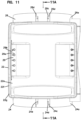
Figure 11 is a top view of the housing shown inFigure 10 . -
Figure 11A is a cross-sectional view of the housing shown inFigure 9 , taken along theline 11A-11A inFigure 11 . -
Figure 12 is a first side view of the housing shown inFigure 10 . -
Figure 13 is a second side view of the housing shown inFigure 12 . -
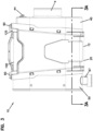
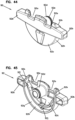
Figure 14 is a first perspective view of the outlet assembly of the air cleaner shown inFigure 1 . -
Figure 15 is a second perspective view of the outlet assembly shown inFigure 14 . -
Figure 16 is an end view of the outlet assembly shown inFigure 14 . -
Figure 17 is a side view of the outlet assembly shown inFigure 14 . -
Figure 18 is an end view of the outlet assembly shown inFigure 14 . -
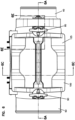
Figure 18A is a cross-sectional view of the outlet assembly shown inFigure 14 , taken along theline 18A-18A inFigure 18 . -
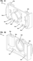
Figure 19 is a partially exploded perspective view of the inlet assembly of the air cleaner shown inFigure 1 . -
Figure 20 is a first perspective view of the inlet assembly shown inFigure 19 . -
Figure 21 is an end view of the inlet assembly shown inFigure 19 . -
Figure 22 is a side view of the inlet assembly shown inFigure 19 . -
Figure 23 is a cross-sectional side view of the inlet assembly shown inFigure 19 , taken along the line 23-23 inFigure 21 . -
Figure 24 is a is a perspective view of the inlet assembly shown inFigure 19 with the precleaner assembly removed. -
Figure 25 is a perspective view of the inlet assembly shown inFigure 24 with the dust ejector assembly removed. -
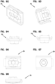
Figure 26 is a perspective view of the dust ejector port of the inlet assembly shown inFigure 19 . -
Figure 27 is a side view of the dust ejector port shown inFigure 26 . -
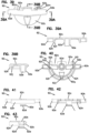
Figure 28 is a first perspective view of the dust ejector port clip of the inlet assembly shown inFigure 19 . -
Figure 29 is a second perspective view of the dust ejector port clip shown inFigure 28 . -
Figure 30 is a top view of the dust ejector port clip shown inFigure 28 . -
Figure 31 is an end view of the dust ejector port clip shown inFigure 28 . -
Figure 32 is a top view of one of the lock mechanisms of the air cleaner shown inFigure 1 . -
Figure 32A is a cross-sectional view of the lock mechanism shown inFigure 32 , taken along theline 32A-32A shown inFigure 32 . -
Figure 33 is a bottom view of the lock mechanism shown inFigure 32 . -
Figure 34 is a first end view of the lock mechanism shown inFigure 32 . -
Figure 35 is a second end view of the lock mechanism shown inFigure 32 . -
Figure 35A is a cross-sectional view of the lock mechanism shown inFigure 32 , taken along theline 35A-35A shown inFigure 35 . -
Figure 36 is a top perspective view of the lock mechanism shown inFigure 32 with the cover portion removed. -
Figure 37 is a bottom exploded perspective view of the lock mechanism shown inFigure 32 . -
Figure 38 is a top exploded perspective view of the lock mechanism shown inFigure 32 . -
Figure 39 is a top view of an operator part of the lock mechanism shown inFigure 32 . -
Figure 39A is a cross-sectional view of the operator part shown inFigure 39 , taken along theline 39A-39A inFigure 39 . -
Figure 39B is a cross-sectional view of the operator part shown inFigure 39 , taken along theline 39B-39B inFigure 39 . -
Figure 40 is a bottom view of the operator part shown inFigure 39 . -
Figure 41 is a first end view of the operator part shown inFigure 39 . -
Figure 42 is a second end view of the operator part shown inFigure 39 . -
Figure 43 is a side view of the operator part shown inFigure 39 . -
Figure 44 is a top perspective view of the operator part shown inFigure 39 . -
Figure 45 is a bottom perspective view of the operator part shown inFigure 39 . -
Figure 46 is a top view of a base part of the lock mechanism shown inFigure 32 . -
Figure 46A is a cross-sectional view of the base part shown inFigure 46 , taken along theline 46A-46A inFigure 46 . -
Figure 46B is a cross-sectional view of the base part shown inFigure 46 , taken along theline 46B-46B inFigure 46 . -
Figure 47 is a bottom view of the base part shown inFigure 46 . -
Figure 48 is a first end view of the base part shown inFigure 46 . -
Figure 49 is a second end view of the base part shown inFigure 46 . -
Figure 50 is a side view of the base part shown inFigure 46 . -
Figure 51 is a top perspective view of the base part shown inFigure 46 . -
Figure 52 is a bottom perspective view of the base part shown inFigure 46 . -
Figure 53 is a perspective view of a lock spring of the lock mechanism shown inFigure 32 . -
Figure 54 is a top view of the lock spring shown inFigure 53 . -
Figure 55 is a side view of the lock spring shown inFigure 53 . -
Figure 56 is a top perspective view of a retaining ring of the lock mechanism shown inFigure 32 . -
Figure 57 is a bottom perspective view of the retaining ring shown inFigure 56 . -
Figure 58 is a top view of the retaining ring shown inFigure 56 . -
Figure 59 is a side view of the retaining ring shown inFigure 56 . -
Figure 60 is a perspective view of a primary filter cartridge of the air cleaner shown inFigure 1 . -
Figure 61 is a side view of the filter cartridge shown inFigure 60 . -
Figure 61A is a perspective view of a representative seal member of the filter cartridge shown inFigure 60 . -
Figure 61B is a cross-sectional side view of a first portion of the seal member shown inFigure 61A . -
Figure 61C is an enlarged portion of a second portion of the seal member shown inFigure 61A . -
Figure 62 is a top view of the filter cartridge shown inFigure 60 . -
Figure 63 is a bottom view of the filter cartridge shown inFigure 60 . -
Figure 64 is an inlet end view of the filter cartridge shown inFigure 60 . -
Figure 65 is an outlet end view of the filter cartridge shown inFigure 60 . -
Figure 66 is a first perspective view of an outer shell of the filter cartridge shown inFigure 60 . -
Figure 67 is a second perspective view of the outer shell shown inFigure 66 . -
Figure 68 is an inlet end view of the outer shell shown inFigure 66 . -
Figure 69 is an outlet end view of the outer shell shown inFigure 66 . -
Figure 70 is a perspective view of a media pack of the filter cartridge shown inFigure 60 . -
Figure 71 is a perspective view of a secondary filter cartridge of the air cleaner shown inFigure 1 . -
Figure 72 is an inlet end view of the filter cartridge shown inFigure 71 . -
Figure 73 is an outlet end view of the filter cartridge shown inFigure 71 . -
Figure 74 is a side view of the filter cartridge shown inFigure 71 . -
Figure 75 is a perspective view of a first seal member of the filter cartridge shown inFigure 60 . -
Figure 76 is a perspective view of a second seal member of the filter cartridge shown inFigure 60 . -
Figure 77 is a cross-sectional view of the first and second seal members shown inFigures 75 and 76 . -
Figure 78 is a perspective view of a mounting structure of the air cleaner shown inFigure 1 . -
Figure 79 is a top view of the mounting structure shown inFigure 78 . -
Figure 80 is a bottom view of the mounting structure shown inFigure 78 . -
Figure 81 is a side view of the mounting structure shown inFigure 78 . -
Figure 82 is an end view of the mounting structure shown inFigure 78 . -
Figure 83 is an exploded perspective view of the mounting structure shown inFigure 78 . -
Figure 84 is a perspective view of a first part of the mounting structure shown inFigure 78 . -
Figure 85 is a top view of the mounting structure first part shown inFigure 84 . -
Figure 86 is a side view of the mounting structure first part shown inFigure 84 . -
Figure 87 is an end view of the mounting structure first part shown inFigure 84 . -
Figure 88 is a perspective view of a second part of the mounting structure shown inFigure 78 . -
Figure 89 is a top view of the mounting structure second part shown inFigure 84 . -
Figure 90 is a side view of the mounting structure second part shown inFigure 84 . -
Figure 91 is an end view of the mounting structure second part shown inFigure 84 . -
Figure 92 is a first perspective view of a mounting arrangement mounting clip of the air cleaner shown inFigure 1 . -
Figure 93 is a second perspective view of the mounting clip shown inFigure 92 . -
Figure 94 is a first end view of the mounting clip shown inFigure 92 . -
Figure 95 is a second end view of the mounting clip shown inFigure 92 . -
Figure 96 is a top view of the mounting clip shown inFigure 92 . -
Figure 97 is a bottom view of the mounting clip shown inFigure 92 . -
Figure 98 is a side view of the mounting clip shown inFigure 92 . -
Figure 99 is a perspective view of a spacer module of the air cleaner shown inFigure 1 . -
Figure 100 is a second perspective view of the spacer module shown inFigure 99 . -
Figure 101 is a side view of the spacer module shown inFigure 99 . -
Figure 102 is a front view of the spacer module shown inFigure 99 . -
Figure 103 is a top view of the spacer module shown inFigure 99 . -
Figure 104 is a bottom view of the spacer module shown inFigure 99 . -
Figure 105 is a rear view of the spacer module shown inFigure 99 . -
Figure 105A is a cross-sectional view of the spacer module shown inFigure 99 , taken along theline 105A-105A inFigure 105 . -
Figure 106 is a perspective view of the air cleaner shown inFigure 1 , with the lock mechanisms in a locked position. -
Figure 107 is a perspective view of the air cleaner shown inFigure 1 with the air filter cartridge removed and the lock mechanisms in an unlocked position. - Herein, example filter assemblies, filter cartridges, features and components therefor are described and depicted. A variety of specific features and components are characterized in detail. Many can be applied to provide advantage. There is no specific requirement that the various individual features and components be applied in an overall assembly with all of the features and characteristics described, however, in order to provide for some benefit in accord with the present disclosure. It is noted that a plurality of embodiments are depicted and described. The embodiments are not meant to be exclusive with respect to features depicted. That is, selected features of one embodiment can be applied in one or more of the other embodiments if desired, to advantage. In many examples, the filter assembly depicted is an air cleaner assembly, for example, used to filter intake air for an internal combustion engine. Additional applications are possible, for example, applications in which the filter assembly is a crankcase ventilation filter assembly, in which the filter cartridge is used to filter crankcase blowby gases which include, typically, both particulate and liquid contaminant therein. Both type of filter assemblies are generally "gas filter assemblies," since the carrier stage being filtered is gas (air or crankcase ventilation gases). While the techniques described herein will typically be used in application for gas filtration, they can be used in the filtration of other materials, for example, liquids, if desired.
- Referring to
Figures 1-9 , aspects of anair cleaner 10 in accordance with an embodiment of the invention are presented. As shown, theair cleaner 10 includes ahousing assembly 12 including amain housing body 20 defining within which aremovable filter cartridge 100 is disposed. Theair cleaner 10 includes ahousing assembly 12 with ahousing body 20 defining an interior region 20a within which a primaryremovable filter cartridge 100 is disposed. Thehousing assembly 12 further includes anoutlet assembly 40 that is positioned for exit of filtered air. In the embodiment presented, theair outlet assembly 40 defines an interior region 40a within which a secondaryremovable filter cartridge 200 is disposed Theoutlet assembly 40 can be made separately from thehousing body 20 and attached thereto, or it can be integrally constructed as a portion of thehousing body 20. Thehousing assembly 12 further includes aninlet assembly 50 through which air to be filtered enters theassembly 10. Theinlet assembly 50 can be made separately from thehousing body 20 and attached thereto, or it can be integrally constructed as a portion of thehousing 20. In the embodiment disclosed, and as explained in detail later in this section, thehousing assembly 12 is modular in configuration in which the outlet andinlet assemblies housing body 20. - The
air cleaner 10 includes anaccess cover 125 to provide access to the interior region 20a of thehousing body 20, such as for placement and removal offilter cartridges access cover 125 may be a separate component or may be an integral feature of another component of theair filter cartridge 100, for example integral with the circumferential shell of thefilter cartridge 100. In the embodiment disclosed herein, theaccess cover 125 is integral to theair filter cartridge 100. In one aspect of the disclosure, theaccess cover 125, and thus thefilter cartridge 100, are secured to thehousing body 20 via a pair of connectors or lockmechanisms 90. - In one aspect, the
air filter cartridge 100 can be configured such that it has an axis of symmetry about a plane passing through the longitudinal axis of theair filter cartridge 100. Such a configuration can allow for theair filter cartridge 100 to be installed in either direction while still interacting in a satisfactory way with the mating parts of thehousing body 20 andlock mechanisms 90. - Referring to
Figures 10-13 , thehousing body 20 is shown in isolation. As presented, thehousing body 20 is unitarily formed as a single component from a polymeric material, such as nylon, polypropylene, or ABS plastic. In one aspect, thehousing body 20 extends between a first end 20a and asecond end 20b and defines andinterior region 20i. Thehousing body 20 can be characterized as having acentral portion 22, aninlet portion 24, and anoutlet portion 26. Although the terms "inlet portion" and "outlet portion" are used herein, it should be understood that, because of the configuration of thehousing body 20, theinlet portion 24 can serve as the outlet end of thehousing body 20 and theoutlet portion 26 can serve as the inlet portion of thehousing body 20. In general, thecentral portion 22 retains thefilter cartridge 100, theinlet portion 24 secures theair inlet assembly 50 to thehousing body 20 and also supports one of thelock mechanisms 90, and theoutlet portion 26 secures theair outlet assembly 40 to thehousing body 20 and also supports theother lock mechanism 90. - In one aspect, the
central portion 22 of thehousing body 20 is defined by asidewall 22a extending between afirst end wall 22b proximate theinlet portion 24 and asecond end wall 22c proximate theoutlet portion 26. Each of the first andsecond end walls openings housing body 20. Thecentral portion 22 further defines an access opening 22f through which thefilter cartridge 100 can be installed. Theaccess opening 22f is also sized such that theoutlet assembly 40 and theinlet assembly 50 can be inserted through the access opening 22f during assembly of thehousing assembly 12. In one aspect, theaccess opening 22f is provided with a grooved structure defining anopen channel 22g for receiving a seal member, such as an O-ring, such thataccess cover 125 can be adequately sealed against thehousing body 20. Referring toFigures 106 and107 , an alternative air cleaner design is shown in which theaccess opening 22f has a varying profile with a transversely or radially recessed portion 22f1 that can be used to enhance positive location of thefilter cartridge 100 during insertion. - The
inlet portion 24 of thehousing body 20 is shown as being provided with acircumferential sidewall 24a with a rectangular shape with rounded ends or corners (e.g. a race track shape). Within thesidewall 24a, a plurality of oppositely arranged and spaced apartapertures 24b are provided. Theapertures 24b are for receiving cooperatively shaped latch members of theair inlet assembly 50 to facilitate a snap-fit type connection between thehousing body 20 and theair inlet assembly 50. Theinlet portion 24 is also provided with a mountingstructure 24c proximate the access opening 22f. The mountingstructure 24c provides a structure to which thelock mechanism 90 can be mounted. As shown, the mountingstructure 24c is defined by a pair of spaced apart, parallel L-shaped channel orrib members 24d extending in a lengthwise direction of thehousing body 20. Theinlet portion 24 is further provided with a cut-outportion 24e within thesidewall 24a to facilitate mounting of a dust ejector in a desired location and orientation, as is explained later in this section. - The
outlet portion 26 of thehousing body 20 is shown as being provided with acircumferential sidewall 26a with a rectangular shape with rounded ends or corners (e.g. a race track shape). Within thesidewall 26a, a plurality of oppositely arranged and spaced apartapertures 26b are provided. Theapertures 26b are for receiving cooperatively shaped latch members of theair outlet assembly 40 to facilitate a snap-fit type connection between thehousing body 20 and theair outlet assembly 40. Theoutlet portion 26 is also provided with a mountingstructure 26c proximate the access opening 22f. The mountingstructure 26c provides a structure to which thelock mechanism 90 can be mounted. As shown, the mountingstructure 26c is defined by a pair of spaced apart, parallel L-shaped channel orrib members 26d extending in a lengthwise direction of thehousing body 20. Although not shown, theoutlet portion 26 can be further provided with a cut-out portion similar to 24e within thesidewall 26a to facilitate mounting of a dust ejector in a desired location and orientation where the air cleaner is configured for air to flow from theportion 26 to theportion 24. - Referring to
Figures 14 to 18 , theoutlet assembly 40, is shown in further detail. For the purpose of clarity, thefilter cartridge 200 is not shown as being installed within the outlet assembly atFigures 14 to 18 . As presented, theoutlet assembly 40 includes anoutlet body 42 andflow restriction indicator 44. Theflow restriction indicator 44 is a dial-type gauge that snap-fits into theoutlet assembly 40. As shown, theoutlet body 42 is defined by asidewall 42a extending between a first end 42b and a second end 42c. In one aspect, thesidewall 42a includes a contouredportion 42d for receiving and sealing with a portion of aseal member 204 associated with thesecondary filter cartridge 200. The interior of thesidewall 42a forms the remaining portion of the seal interface with the secondary filtercartridge seal member 204. Thesidewall 42a is also shown as being provided withlatch portions 42e, each of which having a rampedsurface 42f and a shoulder surface 42g. Thelatch portions 42e interact with theapertures 26b in thehousing body 20 such that a snap-fit connection can be formed between thehousing assembly 20 and theoutlet assembly 40. - The
outlet assembly 40 is also shown as being provided with aflange structure 46 adjoining the first end 42b of theoutlet body sidewall 42a. In one aspect, theflange structure 46 is defined by afirst flange portion 46a and asecond flange portion 46c that each extending radially outwardly from thesidewall 42a. In one aspect, theflange portions surface 46b on one side of theflange structure 46 and a sealingsurface 46c on an opposite side of theflange structure 46. - In the embodiment shown, the sealing
surface 46c of thefirst flange portion 46a is disposed at an angle a1 to a longitudinal axis X of theair cleaner 10 andoutlet assembly 40. In one aspect, the angle a1 is an oblique or non-orthogonal angle. In the example shown, the angle a1 is 95 degrees. However, other angles are possible, such as angles ranging between 90 and 135 degrees, for example 100 degrees. In some examples, the angle a1 is minimized such that the surface area of thesidewall 42a between theflange portions interior region 20i is less able to collect on the resulting ledge area of thesidewall 42a, for example when thefilter cartridge 100 is being removed. In one aspect, the first andsecond flange portions second flange portions media pack 110 is orthogonal to the longitudinal axis X, the angles a1 and a2 can also be said to be at an oblique angle to theoutlet end 114. As the seal surfaces 132b, 132c of theseal member 132 can be defined by the angles a1, a2 of theflange portions - When the
outlet assembly 40 is inserted through the housing body access opening 22f such that theoutlet assembly 40 resides within theinterior region 20i of thehousing body 20, theoutlet assembly 40 can be pushed forward towards the housing body outlet portion 26 (or inlet portion 24) until the mountingsurface 46b abuts theend wall 22c of thehousing body 20. This position is most easily seen in the cross-sectional views ofFigures 6A and6B . Theend wall 22c provides a positive stop against the mountingsurface 46b of thefirst flange portion 46a. During this action, the rampedsurface 42f of each of thelatch portions 42e ride along the interior surface of thesidewall 26a until theoutlet body 42 is sufficiently inserted for thelatch portions 42e to be fully received into theapertures 26b. At this point, the shoulder surfaces 42g of thelatch portions 42e lock against an edge of theapertures 26b in a snap-fit type of connection, wherein theoutlet housing 42 is locked from further movement by thelatch portions 42e and theend wall 22c. - In one aspect, the
second flange portion 46c adjoins thefirst flange portion 46a to form theseal surface 46d opposite the mountingsurface 46b. Theseal surface 46d provides a surface against which a correspondingly shaped seal member of thefilter cartridge 100 can form a seal. As thefirst flange portion 46a andsecond flange portion 46c are arranged in a non-parallel relationship, theportion 46e of theseal surface 46d defined by thefirst flange portion 46a is disposed at the angle a2 to theportion 46f of theseal surface 46d defined by thesecond flange portion 46c. Accordingly, theseal surface 46d can be said to have a compound shape or profile. At thelocation 46g of theseal surface 46d where the first andsecond seal portions seal surface 46d is curved such that a smooth transition exists. Stated another way, the first andsecond seal portions curved portion 46g connecting theportions seal surface 46d is curved rather than being planar. For example, either or both of the first andsecond seal portions first seal portion 46e represents less than half of thetotal seal surface 46d, and thus has a lesser length than that of thesecond seal portion 46f. - The
outlet assembly 40 is also provided with an outlet end 48 defined by anend wall 48a and anoutlet tube 48b to which a hose or duct can be connected. The outlet end 48 is also shown as including internal sidewalls orribs 48c for interacting with thefilter cartridge 200. The outlet end 48 is further shown as also including a sidewall orwell 48d for receiving therestriction indicator 44. - One advantage of the presented configuration, due to the disclosed modular design, is that differently configured
outlet assemblies 40 can be mounted onto thehousing body 20 to suit any particular application. For example, the outlet assembly could be provided with a differently sized or shaped outlet tube or duct, could be provided without a restriction indicator, or could be provided with additional ports for the installation of electronic sensors. Accordingly, the disclosure is not necessarily limited to the specific outlet assembly configuration described herein as other or different features may be included. - Referring to
Figures 19-31 , aspects of theinlet assembly 50 are shown in greater detail. As presented, theinlet assembly 50 includes aninlet body 52, aprecleaner assembly 60, and adust ejection assembly 66. In one aspect, theprecleaner assembly 60 generally is used to clean selected material or contaminants carried by an air stream into the aircleaner assembly 10 before the air reaches thefilter cartridge 100 positioned therein. Theprecleaner 60 generally includes asidewall 62a bounding an end wall 62b through which a plurality ofcyclonic separator tubes 64 extend. In the embodiment shown in the drawings, 42separator tubes 64 are provided. More orfewer separator tubes 64 can be provided. - The
inlet body 52 is also shown as including asidewall 52a bounding anend wall 52b. A plurality ofreceptacles 54 are shown as being provided on and extending through theend wall 52b. Thereceptacles 54 are received into the outlets of theseparator tubes 64 when theprecleaner assembly 60 is installed into theinlet body 52, wherein thesidewall 62a slides within thesidewall 52a. In the example presented, theprecleaner assembly 60 can be secured via afastener 62c (e.g. a threaded screw or bolt) extending into a threadedopening 52c in theend wall 52b of theinlet body 52. - In operation, contaminants are separated to the outside walls of the
separator tubes 64 and are collected within the interior space defined betweenend walls 62b, 52b and thesidewall 52a and are then ejected out of the dustejection port assembly 66. The relatively contaminant free air passing through the central portions of theseparator tubes 64 is received by thereceptacles 54 where the air can pass through theend wall 52b and into theinterior region 20i where the air can be received by thefilter cartridge 100 for further cleaning. - As can be most easily seen at
Figures 19 and23-21 , the dust ejection assembly including adust ejection port 67 mounted through an opening in theinlet body sidewall 52a and a retainingclip 68 securing thedust ejection port 67 to thesidewall 52a. As opposed to typical prior art assemblies in which the dust ejection port is molded into the precleaner assembly or part of the air cleaner housing, thedust ejection assembly 66 disclosed herein is removable and can be mounted in multiple locations, where theair cleaner 10 is provided withmultiple openings 52d. Theinlet assembly 50 is installed through the access opening 22f of thehousing body 20 in a manner similar to that already described for theinlet assembly 40. The removability of thedust ejection assembly 66 facilitates this assembly process, as insufficient clearance would result if thedust ejection port 67 were non-removable and assembly through the access opening 22f were attempted. Once theinlet assembly 50 is installed onto themain body 20, thedust ejection port 67 can be inserted into theopening 52d in theinlet body 52. - With reference to
Figures 26-31 , thedust ejection port 67 is defined by atubular sidewall 67a that extends to aflange 67b. During insertion of thedust ejection port 67 into the inlet body opening 52d in a direction from the outside of thesidewall 52a towards the interior defined by thesidewall 52a, theflange 67b acts as a stop to prevent further insertion into the interior. In one aspect, theflange 67b is provided with a complementary shape to the profile of thesidewall 52a such that a generally flush fit arrangement between theflange 67b and thesidewall 52a exists. In the example shown, both thesidewall 52a, at the location of opening 52d, and theflange 67b are curved. However, where the mounting location of thedust ejection assembly 66 is along a flat side of theinlet body sidewall 52a, theflange 67b can be planar or flat. - The
dust ejection port 67 is further provided with a pair of retaining flanges orears 67c that pass through theinlet body opening 52d when theflange 67b is abutted with thesidewall 52a. The retainingflanges 67b are received by the retainingclip 68 which includes asidewall 68a defining anopening 68b with a narrowedopening area 68c for receiving a narrowed neck region of thetubular sidewall 67a between theflanges dust ejection port 67. The narrowedopening area 68c enables for a snap-fit type attachment between thedust ejection port 67 and the retainingclip 68. Once the dustejection port sidewall 67a is inserted through theopening 52d, the retainingclip 68 is inserted onto theejection port sidewall 67a on the side of theinlet body sidewall 52a opposite of theflange 67b (i.e. on the interior side ofsidewall 52a). Once inserted, the retainingclip 68 operates against the retainingflanges 67b to prevent thedust ejection port 67 from being removed from theinlet body 52. As indicated atFigures 28 , theclip 68 has a width w1 at the distal end of the clip which increases to a width w2 towards the opposite end of theclip 68 to form a ramp-like structure. Thus, as the retainingclip 68 is inserted, the increasing thickness of theclip 68 acts to bind theejection port 67 in place such that theejection port 67 is axially secured in place with respect to thesidewall 52a. A handle orlip member 68d is provided on the retainingclip 68 to facilitate manipulation of the retaining clip during insertion and removal. - Ramped sidewall members or
ribs 68e can also be provided to interact with the ends of the retainingflanges 67c to prevent rotation of theejection port 67 with respect to thesidewall 52a. Preventing rotation is advantageous as loosening of the connection between the retainingclip 68 and theejection port 67 could occur with such rotation. - In one aspect, the retaining
clip sidewall 68a is provided with a complementary shape to the profile of thesidewall 52a such that a generally flush fit arrangement between thesidewall 68a and thesidewall 52a exists. In the example shown, both thesidewall 52a, at the location of opening 52d, and thesidewall 68a are curved. However, where the mounting location of thedust ejection assembly 66 is along a flat side of theinlet body sidewall 52a, thesidewall 68a can be planar or flat. - The
sidewall 52a of theinlet body 52 is also shown as being provided withlatch portions 52e, each of which having a rampedsurface 52f and ashoulder surface 52g. Thelatch portions 52e interact with theapertures 24b in thehousing body 20 such that a snap-fit connection can be formed between thehousing assembly 20 and theinlet assembly 50. - The
inlet assembly 50 is also shown as being provided with aflange structure 56 adjoining the second end 42c of theoutlet body sidewall 42a. In one aspect, theflange structure 56 is defined by afirst flange portion 56a and asecond flange portion 56c that extend radially outwardly from thesidewall 52a. In one aspect, theflange portions surface 56b on one side of theflange structure 56 and a sealingsurface 56c on the opposite side of theflange structure 56. - In the embodiment shown, the
first flange portion 56a is disposed at an angle a3 to a longitudinal axis X of theair cleaner 10 andinlet assembly 50. In one aspect, the angle a3 is an oblique or non-orthogonal angle. In the example shown, the angle a1 is 5 degrees. However, other angles are possible, such as angles ranging between 0 and 45 degrees, for example 10 degrees. In one aspect, the first andsecond flange portions second flange portions - When the
outlet assembly 40 is inserted through the housing body access opening 22f such that theinlet assembly 50 resides within theinterior region 20i of thehousing body 20, theinlet assembly 50 can be pushed forward towards the housing body inlet portion 24 (or inlet portion) until the mountingsurface 56b abuts theend wall 22b of thehousing body 20. This position is most easily seen in the cross-sectional views ofFigures 8 and 8A. Theend wall 22b provides a positive stop against the mountingsurface 56b of thefirst flange portion 56a. During this action, the rampedsurface 52f of each of thelatch portions 52e ride along the interior surface of thesidewall 24a until theinlet body 52 is sufficiently inserted for thelatch portions 52e to be fully received into theapertures 24b. At this point, the shoulder surfaces 52g of thelatch portions 52e lock against an edge of theapertures 24b in a snap-fit type of connection, wherein theinlet housing 52 is locked from further movement by thelatch portions 52e and theend wall 22b. - In one aspect, the
flange structure 56 adjoins thefirst flange portion 56a to form theseal surface 56d opposite the mountingsurface 56b. Theseal surface 56d provides an axial surface against which a correspondingly shaped seal member of thefilter cartridge 100 can form a seal. Accordingly, the seal surfaces of the seal members can have the same shape or profile as explained below for the seal surfaces herein. As thefirst flange portion 56a andsecond flange portion 56c are arranged in a non-parallel relationship, theportion 56e of theseal surface 46d defined by thefirst flange portion 56a is disposed at the angle a4 to theportion 56f of theseal surface 56d defined by thesecond flange portion 56c. Accordingly, theseal surface 56d can be said to have a compound shape or profile. At thelocation 56g of theseal surface 56d where the first andsecond seal portions seal surface 56d is curved such that a smooth transition exists. Stated another way, the first andsecond seal portions curved portion 56g connecting theportions seal surface 56d is curved rather than being planar. For example, either or both of the first andsecond seal portions first seal portion 56e represents less than half of thetotal seal surface 56d, and thus has a lesser length than that of thesecond seal portion 56f. - One advantage of the presented configuration, due to the disclosed modular design, is that differently configured
inlet assemblies 50 can be mounted onto thehousing body 20 to suit any particular application. For example, aninlet assembly 50 with no precleaner, an inlet duct, a different precleaner design, and/or dust ejection assembly could be provided. Accordingly, the disclosure is not necessarily limited to the specific inlet assembly configuration described herein as other or different features may be included. - Referring now to
Figures 60-69 , an exemplary embodiment offilter cartridge 100 of aircleaner assembly 10 is illustrated. Thefilter cartridge 100 extends between afirst end 102 and asecond end 104. In one aspect, thefirst end 102 can be characterized as the upstream end of thefilter cartridge 100 while thesecond end 104 can be characterized as the downstream end of thefilter cartridge 100. Thefilter cartridge 100 can be considered to be the main or primary filter cartridge, and is used to selectively separate a desired amount of particulate or containment material. -
Filter cartridge 100 is generally a service part or removable component, such that it is periodically removable and replaceable as desired or necessary during the lifetime of theair cleaner 10. In particular, when thecartridge 100 becomes occluded or otherwise needs to be replaced, theaccess cover 125 is unlocked from thehousing 20, and theoccluded filter 100 is removed by pulling the access cover in a direction R1 away from thehousing 20 via ahandle 127 associated with theaccess cover 125. After such removal, anotherfilter 100 can be placed in thehousing 20 by inserting thefilter cartridge 100 in an insertion direction I1. In one aspect, the directions I1 and R1 are orthogonal to the longitudinal axes X, X1 of thefilter cartridge 100 andhousing 20. In the example shown, theaccess cover 125 is integral to thefilter cartridge 100 and thus serves as the previously describedaccess cover 125. Similarly, thehandle 127 is integrally formed with theaccess cover 125. In one aspect, thehandle 127 has a length that is a majority of the length of themedia pack 110. As mentioned previously,Figures 106 and107 show thefilter cartridge 100 that theaccess opening 22f can have a varying profile with a recessed portion 22f1. In such an embodiment, theaccess cover 125 can be formed with a complementary shape to the access opening 22f such that theaccess cover 125 has a contoured shape with a protrudingportion 125a that mates or abuts with the recessed portion 22f1 - The
filter cartridge 100 generally includes amedia pack 110, ashell 120 integrally including theaccess cover 125 and thehandle 127, afirst sealing member 130 at the inlet end of themedia pack 110, and asecond sealing member 132 at the outlet end of themedia pack 110. The sealingmembers members members seal members Figures 75-77 . - In the example shown, the
media pack 110 hasinlet flow face 112 for receiving unfiltered air or pre-cleaned air from the precleaner (if provided) and anoutlet flow face 114 for delivering filtered air. Themedia pack 110 is shown in isolation atFigure 70 . In the example shown, themedia pack 110 has an obround cross-sectional shape. However, other shapes are possible, such as round, oval, and rectangular cross-sectional shapes. In one aspect, themedia pack 110 defines anouter perimeter 116 extending between the inlet and outlet flow faces 112, 114. In the example shown, themedia pack 110 is formed from a coiled media construction, for example a media construction having a fluted (typically corrugated) media sheet and a facing media sheet that together define parallel flutes to form a fluted or z-filter media construction. Suitable media constructions for themedia pack 110 are discussed in more detail in the Media Types and Configurations section. - In one aspect, the
shell 120 of thefilter cartridge 100 is formed from a polymeric material, such as nylon, polypropylene, or ABS plastic. Theshell 120 is shown in isolation atFigures 66-69 . In one aspect, theshell 120 defines aperimeter wall 122 that surrounds theouter perimeter 116 of themedia pack 110. Agrid structure 123 is also shown as being provided with theshell 120 for supporting theoutlet flow face 114 of themedia pack 110. Theshell 120 may be secured to themedia pack 110 by an adhesive. Theperimeter wall 122 may surround the entirety of the media packouter perimeter 116, as shown, or surround a portion of the media packouter perimeter 116. As noted previously, theaccess cover 125 and handle 127 are integrally formed with the shell. As shown, theaccess cover 125 includes amain body 125a that is sized and shaped to mate against and cover the access opening 22f of thehousing body 20. Themain body 125a defines a sealing surface 125b against which a seal associated with thehousing body 20 can form a seal. In the example shown, thehandle 127 is formed with theaccess cover 125 such that anopen space 127a exists between thehandle 127 and thecover 125 to allow an operator to grasp thehandle 127. Theopen space 127a can be defined as a recess beneath one or both sides of thehandle 127 or can be a completely open space, as shown in the drawings. In the example shown, theaccess cover 125 can be provided withindicia 125c, such as text and directional arrows, to provide an indication to an operator as to the proper installation orientation of thefilter cartridge 100. - In one aspect, first and second
seal support flanges perimeter wall 122. Theseal support flanges seal members seal support flanges seal members assembly sealing surface 46d and the inletassembly sealing surface 56d. Accordingly, theseal support flange 124 defines asupport surface 124a having afirst portion 124b disposed at angle a4 and an adjoiningsecond portion 124c, wherein the first andsecond portions support flange 124 imparts similar features onto theseal member 130 such that aseal surface 130a of theseal member 130 has afirst portion 130b at the angle a3 and an adjoiningsecond portion 130c at the angle a4 with respect to thefirst portion 130b. In the example shown, the media packinlet flow face 112 is shown as being orthogonal to the longitudinal axis X1 of thefilter cartridge 100. Accordingly, the support flangefirst portion 124a and the sealfirst portion 130b can be said to form an angle a5 with the plane P1 defining the inlet flow face that is equal to the angle a3 minus 90 degrees. As such, the angle a5 in the example shown is 10 degrees. - The
seal support flange 126 defines asupport surface 126a having afirst portion 126b disposed at the angle a1 and an adjoiningsecond portion 124c disposed at the angle a2 with respect to thefirst portion 126b. The shape of thesupport flange 126 imparts similar features onto theseal member 132 such that aseal surface 132a of theseal member 132 has a first portion 132b at the angle a1 and an adjoiningsecond portion 132c at the angle a2 with respect to the first portion 132b. In the example shown, the media packoutlet flow face 114 is shown as being orthogonal to the longitudinal axis X1 of thefilter cartridge 100. Accordingly, the support flangefirst portion 126a and the seal first portion 132b can be said to form an angle a6 with the plane P2 defining the inlet flow face that is equal to the angle a1 minus 90 degrees. As such, the angle a6 in the example shown is 10 degrees. In one aspect, theseal surfaces media pack 110 or facing in the same general direction as the media pack end) of thefilter cartridge 100. - The
seal members seal members Figures 61A-61C , respectively. With reference toFigure 61B a cross-sectional view of theseal members seal members seal members extensions side 133d of thelip extension 133b interfaces with theseal support flanges flanges seal members top segment 133e wherein the c-shaped channel is oriented 90 degrees to the remainder of theseal member top segment 133e, the open side of the channel faces in the same direction as thelip extension 133c of the remaining segment of theseal member seal members outlet housing assemblies top segment 133e, the distal ends of each of thelip extensions seal members - In one aspect, the seal surface
first portions 130b, 132b form an angle with each as defined by the angles a1 and a3. As shown, this angle is about 20 degrees. In one aspect, the seal surfacesecond portions first portions 130b, 132b are planar while in others thefirst portions 130b, 132b are curved. In some examples, thesecond portions second portions first portions 130b, 132b and thesecond portions first portions 130b, 132b are planar and thesecond portions first portions 130b, 132b define a majority of the length of the seal surfaces and thesecond portions - As a result of the
seal members seal members cover 125 such that theseal members cover 125 as compared to a location proximate the cover 125 (i.e. distance betweenseal members filter cartridge 100 into theinterior region 20i of thehousing body 20 with less compressive resistance from theseal members seal members second portions first portions 130b, 132b (i.e. distance between seals atsecond portions first portions 130b, 132b in direction towards cover). These features allow for thefilter cartridge 100 to simultaneously have axial seals while being transversely or side-loaded in the insertion direction I1, wherein theseals housing 20 without further requiring any movement of thefilter cartridge 100 within thehousing body 20 along the axis X1 in order to form a seal with thehousing 20. - Another advantage of the disclosed configuration is that the filter cartridge seals against the inlet and
outlet housing assemblies housing body 20. Because theseal member 130 forms a seal against theseal surface 56d of theinlet housing assembly 50 and theseal member 132 forms a seal against theseal surface 46d of theoutlet housing assembly 40, it is not necessary for thecover 125 to form a leak-proof seal with thehousing body 20 or for thefilter cartridge 100 to form a leak-proof seal with thehousing body 20. - In one aspect, the
filter cartridge 100 is also shown as being provided with lock interface features 150 at each end. The lock interface features 150 interact with the lockingmechanisms 90 such that thefilter cartridge 100 can be locked in place with respect to thehousing 20. As shown, the lock interface features 150 include anarcuate rib structure 152 and a pair oftab structures 154, each of which is integrally formed on theaccess cover 125. The structure and function of these features are further described in the lock mechanism section. - Referring to
Figure 1A , the exemplary aircleaner assembly 10 includes an optional secondary orsafety filter cartridge 200. Thesafety filter cartridge 200 is shown in isolation atFigures 71 to 74 . Thesafety filter 200 is generally positionable between themain filter cartridge 100 and theoutlet 48b of thehousing 20. In a typical arrangement, the safely filter 200 is removably positioned within the aircleaner assembly 10 and would also typically be considered to be a service component that is removable and replaceable, as desired and/or necessary. - The exemplary embodiment of
safety filter 200 includes anouter frame 202 that carries aseal member 204 having a pair of parallel lip seals, and generally matches the size and shape of the inner area of the housing outlet body 42 (e.g. straight segmentedportions 42d together with the straight sides of the interior surface of thesidewall 42a) and can seal to theoutlet body 42, preferably with no gaps. In this way, thesafety filter 200 can be pressed into the housing with a friction fit against the wall of the housing so that no air can reach the outlet without first going through the safety filter. Thesafety filter 200 can also includefiltration media 220, such as pleated media. Ahandle 206 may also be provided to aid in installing and removing thefilter cartridge 200 from thehousing 20 via the access opening 22f. - Any type of filter media can be used as the media pack for the
filter cartridges U.S. Patent Nos. 5,820,646 ;5,772,883 ;5,902,364 ;5,792,247 ;5,895,574 ;6,210,469 ;6,190,432 ;6,350,296 ;6,179,890 ;6,235,195 ;D399,944 ;D428,128 ;D396,098 ;D398,046 ; andD437,401 . - One type of z-filter media utilizes two specific media components joined together to form the media construction. The two components include a fluted (typically corrugated) media sheet and a facing media sheet. The facing media sheet is typically non-corrugated, although it is possible for it to also be corrugated (e.g., perpendicular to the flute direction) as described in
U.S. Provisional Application No. 60/543,804, filed February 11, 2004 PCT WO 05/077487 on August 25, 2005 - The fluted media sheet and the facing media sheet are used together to define media having parallel inlet and outlet flutes. In some instances, the fluted sheet and facing sheet are secured together and are then coiled as a media strip to form a z-filter media construction. Such arrangements are described, for example, in
U.S. Patent Nos. 6,235,195 and6,179,890 . - In certain other arrangements, some non-coiled sections or strips of fluted (typically corrugated) media secured to facing media, are stacked with one another, to create a filter construction.
- Corrugated media is a specific form of fluted media, wherein fluted media has individual flutes or ridges (for example formed by corrugating or folding) extending thereacross. The term "corrugated" is used herein to refer to structure in media, such as media having a flute structure resulting from passing the media between two corrugation rollers (e.g., into a nip or bite between two rollers, each of which has surface features appropriate to cause corrugations in the resulting media).
- Serviceable filter element or filter cartridge configurations utilizing z-filter media are sometimes referred to as "straight through flow configurations" or by variants thereof. In general, serviceable filter elements or cartridges have an inlet flow end (or face) and an opposite exit flow end (or face), with flow entering and exiting the filter cartridge in generally the same straight through direction. The term "serviceable" in this context is meant to refer to a media containing filter cartridge that is periodically removed and replaced from a corresponding fluid (e.g. air) cleaner.
- Referring to
Figures 1 to 3 , it can be seen that theconnectors 90, hereafter referred to aslock mechanisms 90, are provided at each end of thefilter cartridge 100. As described previously, thefilter cartridge 100 includesfeatures 150 includingarcuate ribs 152 andtab structures 154 that are integrally formed with theaccess cover 125 of theshell 120. Each of thetabs 154 is received in acorresponding recess 92a of anoperator part 92 of thelock mechanism 90. Thefilter cartridge 100 cannot be fully inserted into thehousing 20 unless thelock mechanisms 90 are rotated into a fully unlocked position such that therecesses 92a align with thetabs 154. - Referring to
Figures 39-45 , theoperator part 92 is shown in further detail. As shown, theoperator part 92 includes theaforementioned recess 92a, a pair ofhandle portions 92b for enabling a user to grasp and rotate theoperator part 92, acover portion 92c, astem portion 92d extending from thecover portion 92c, a retaininggroove 92e defined within thestem portion 92d, an arc-shapedrib portion 92f defining a groove orchannel 92g between therib portion 92f and asidewall portion 92h of thecover portion 92c, a pair of recessedareas 92i at the location where therib portion 92f meets thesidewall portion 92h, and acentral indexing member 92j extending between therib portion 92f and thesidewall portion 92h. Thesidewall portion 92h is also shown as including lead in or rampedportions 92h at the ends of the of thesidewall portion 92h to better allow thecover portion 92c to be rotated over the filtercartridge access cover 125. - Referring to
Figures 46-52 , abase part 94 of thelock mechanism 90 is shown in further detail. As shown, thebase part 94 includes amain body 94a within which acentral aperture 94b is defined, a lockspring retaining feature 94c including a pair ofapertures 94f a pair ofapertures 94g and acentral tab 94h, a pair of arc-shapedrib portions 94d, and a pair of attachment features 94e for securing thelock mechanism 90 to thehousing 20. In one aspect, the attachment features 94e include a pair of L-shapedchannels 94e that receive the correspondingly shaped L-shapedrib members housing body 20. - Referring to
Figures 53 to 55 , alock spring 96 of thelock mechanism 90 is shown in further detail. As shown, thelock spring 96 extends from abase portion 96a to rampedportions 96b which in turn extends totab portions 96c. Thelock spring 96 further includes alatch portion 96d projecting from thetab portion 96c. Thelatch portion 96d includes alatch face 96e for engaging against anedge 92m of thecover portion 92. Thelock spring 96 is also shown as being formed withtabs 96e and 96f for securing thelock spring 96 to the lockspring retaining feature 94c of thebase part 94. In the example shown, thelock spring 96 is cut from a steel sheet (e.g. spring steel) and bent to shape. - Referring to
Figures 56-59 , a retainingring 98 of thelock mechanism 90 is shown in further detail. The retainingring 98 includes amain body 98a within which acentral aperture 98b is defined. In the example shown, the retainingring 92 is formed from a metal material, such as spring steel. - In one aspect, the lock
spring base portion 94a is received within the lockspring retaining feature 94c such thetabs 96e extend throughopenings central tab 94h of the base part 94and such that the rampedportions 96b extend away from the base partmain body 94a.Figure 36 shows thelock spring 96 attached to thebase portion 94 with thecover 92 removed to better show the connection between thelock spring 96 and thebase portion 94. This configuration allows the lockspring tab portion 96c to be deflectable from a relaxed or resting position (i.e. the raised position in the drawings), as shown at position P1 inFigures 6E and32-36 , to a deflected position (i.e. the lowered position in the drawings)towards themain body 94a, as shown at position P2 inFigure 78 . Theoperator part 92 is mounted to thebase part 94 by passing thestem portion 92d of theoperator part 92 through thecentral aperture 94b of thebase part 94 such that the operatorpart cover portion 92c covers the base partmain body 94a. In this position, theribbed portion 94d of thebase part 94 rests in a groove formed between the operator part ribbed andouter wall 92h. The two parts are secured together by installing the retainingring 98 onto the retaininggroove 92e. - Once the operator and
base parts operator part 92 is rotatable with respect to thebase part 94 from an unlocked position to a locked position. In the unlocked position, theoperator part 92 is aligned such that thetab portion 96c extends into therecess 92a in thecover portion 92c of theoperator part 92 and such that the latch face 96f of the lockingspring 96 rests against theside edge 92m of theoperator part 92. Due to the interaction between the latch face 96f and the operatorpart side edge 92m, theoperator part 92 is unable to be rotated out of the unlocked position with the lockingspring 96 in the resting position. In the event that that theoperator part 92 is rotated past this position without afilter cartridge 100 installed, theoperator part 92 can be easily rotated back to the unlocked position as the rampedface 96e will allow the lockingspring latch portion 96d to easily deflect and slide past theside edge 92f on theoperator part 92. - When the
filter cartridge 100 is installed into thehousing 20, thetabs 154 on theaccess cover 125 contact and deflect the lockingspring 96 of each of thelock mechanisms 90 in a direction towards thebase part 94. This interaction is shown in the schematic presented atFigure 6E as position P2. Once thefilter cartridge 100 is fully installed, eachlatch portion 96d is displaced beyond theside edge 92f thereby allowing theoperator part 92 to be rotated towards the locked position in either a clockwise or counterclockwise direction. As theoperator part 92 is rotated towards the locked position, theribbed portion 92f on theoperator part 92 slides along theribbed structure 152 of thefilter cartridge 100. Thus, theribbed structure 152, which can be characterized as a connection member, works in conjunction with theoperator part 92 to secure the media pack within the air cleaner housing. As thefilter cartridge 100 is a true side-loaded filter cartridge which does not need to be axially displaced after insertion into thehousing 20 to effectuate a seal, thefilter cartridge 100 is configured such that at least a portion of theribbed structure 152 extends axially beyond the inlet/outlet flow end of themedia pack 110. In the particular example shown, the entirety of theribbed structure 152 is axially beyond the inlet/outlet flow end of themedia pack 110. - In the example shown, the locking
mechanisms 90 do not directly effectuate a seal atseal members individual seals members individual sealing surfaces lock mechanisms 90 can be configured to exert a compressive force onto thefilter cartridge 100 and thus theseal members mechanisms 90 do operate to lock thefilter cartridge 100 in place in self centering fashion wherein stress is transferred between thelock mechanisms 90 and cover 125 but without imparting a force onto theseal members seal members lock mechanisms 90 will still function to axially align and fix thefilter cartridge 100 to effectuate a single seal without the need for the presence of the second seal or any other component on the cartridge or housing to effectuate the seal. - Additionally, the retaining
ring 92 is configured such to exert a spring force onto theoperator part 92. Theoperator part 92 is rotated into the locking position until therib 92j of the operator part engages with a stop member ordetent 152i on the arcuate shapedrib structure 152 on thefilter cartridge 100 to aid in retaining theoperator part 92 in the locked position and to provide an installer with tactile feedback of the locked position. During initial rotation of theoperator part 92, therib 92j rides on to of or against therib structure 152 on thefilter cartridge 100 which provides slight resistance to rotation. Once therib 92i reaches thestop member 152i, therib 92i snaps into the recess defined by thestop member 152i, thus simultaneously indexing theoperator part 92 into the locked position and providing tactile feedback. To remove thefilter cartridge 100 from the housing, the operator simply rotates eachoperator part 92 until therecesses 92a align with thetabs 154. - As can be appreciated by the above description, the complementary configuration of the locking
mechanisms 90 andfilter cartridge tabs 154 ensures that the correct filter cartridge is installed into a housing that is actually designed to receive the filter cartridge. If an attempt is made to install a filter cartridge that does not include thetabs 154, thefilter cartridge 100 will fail to enable the lock mechanisms to move to the locked position, thus alerting the installer that an incorrect filter cartridge is installed. Although the tabs and recesses are shown as having a particular shape, other shapes are possible. Different shapes may be used for different air cleaner sizes or designs, thus ensuring the correct filter cartridges are installed appropriate housings throughout an entire product line. - Referring to
Figures 78-93 , details of the mountingarrangement 30 are shown in greater detail. The mountingarrangement 30 is shown as being installed on themain housing body 20 atFigures 1 and3-8 . As shown, the mountingarrangement 30 is shown as including a pair of mountingstructures 32 that are mounted to thehousing body 20 in a spaced apart and parallel arrangement. The mountingarrangement 30 is also shown as including four mountingclips 34. Either of the mountingclips 34 or the mountingstructures 32 can be independently used to mount theair cleaner 10 to a supporting structure with the mountingclips 34 providing a fixed-distance mounting arrangement and the mounting structures providing an adjustable mounting system. Where both mountingstructures 32 and mountingclips 34 are provided, an installer or designer can utilize whichever mounting approach best suits a particular application. As the mountingstructures 32 and mountingclips 34 can be independently used to mount theair cleaner 10 to a supporting structure, anair cleaner 10 can be provided with only the mountingstructures 32 or only the mounting clips 34. - As can be seen at
Figures 9 and12 , thehousing body 20 defines a pair ofchannels 25 defined bysidewalls 25a which receive the mountingstructures 32. Thehousing body 20 is also provided withend walls 25b extending across thesidewalls 25a at each end. Theend walls 25b are shown as includingapertures 25c such that the end walls can receive mounting clips 34. The mounting clips 34 form a portion of the mounting arrangement. Thehousing body 20 is also shown as includingapertures 25d for receiving a portion of the mountingstructures 32 such that the mountingstructures 32 can be secured to thehousing body 20. - With reference to
Figures 78-91 , features of the mountingstructures 32 are shown in greater detail. In one aspect, each mountingstructure 32 includes afirst channel part 32a that receives asecond channel part 32b. As can be most easily seen atFigure 82 , thesecond channel part 32b has a width or dimension that matches thehead 32d of abolt 32c that allows the bolt to slide along the length of thesecond channel part 32b but prevents the bolt from rotating. Thefirst channel part 32a has acentral opening 32e through which thehead 32d can pass such that the head can be received by thesecond channel part 32b. Thefirst channel part 32a additionally haslateral walls 32f that extend towards each other to secure the opposite side of thebolt head 32d. Thus, abolt 32c can be received into thefirst channel part 32a and then into thesecond channel part 32b such that thebolt 32c is slidably secured between thesecond channel part 32b and thewalls 32f. With such a configuration, the position of thebolts 32c can be easily adjusted to align with a given mounting structure. Thebolts 32c are prevented from sliding off either end of thechannel parts end walls 25b on thehousing body 20. - The
second channel part 32b is shown as including an extension part 32g at one end that is received by thehousing body slots 25d and anextension part 32h at the other end that can engage with or interact with the mountingclip 34. The mountingstructure 32 can also be provided with a spacer, fill, or interfence member 32k (e.g. collapsed polymeric tube or moon-shaped polymeric tube) that can be received by the first andsecond channel parts bolts 32c in a fixed position and dampen potential vibration. In one aspect, thefirst channel part 32a can be provided withapertures 32f that receive tabs 32g of thesecond channel part 32b to aid in securing the first andsecond channel parts - Referring to
Figures 92-98 , the retainingclip 34 is shown in greater detail. In one aspect, the retainingclip 34 includes a base portion 34a, a head portion 34b extending from the base portion 34a, and a clip portion 34c extending from the base portion 34a. The head portion 34b includes an aperture 34d, which can be a threaded opening for receiving a mounting bolt. The mountingclip 34 is installed onto theend wall 25b such that the head portion 34b extends through theaperture 25c and such that theend wall 25b is clipped between the base portion 34a and the clip portion 34c. The retainingclip 34 is further provided with a snap member 34e that snaps into therecess 25c when theclip 34 is installed such that theclip 34 is retained onto theend wall 25b via a snap-fit type connection. Theclip member 34 can also be provided with protrusions 34f that can snap into recesses formed in thehousing body 20 to further secure theclip member 34. - Referring to
Figures 3A ,3B ,6B ,6C, and 6D , it can be seen that theair cleaner 10 is provided with apositioning arrangement 70 disposed within awell area 27 of thehousing body 20. In one aspect, thewell area 27 is defined by a pair ofsidewall portions 27a and a sidewall portion 27b. Theportions 27a, 27b are a part of thehousing body sidewall 22a. Thepositioning arrangement 70 is designed to ensure that aproper filter cartridge 100 is installed into theair cleaner 10. In one aspect, the positioning arrangement creates an internal profile within thehousing body 20 that requires thefilter cartridge 100 to have a matching and complementarily shaped profile in order to be received fully into thehousing body 20. In the embodiment shown, thepositioning arrangement 70 is formed by a pair of arrays with spaced apartribs 29b extending from thehousing body sidewall 22a to pinextensions 29a. In the example shown, fivepins 29a andribs 29b are shown on each side of the housingbody interior region 20i. Thepins 29a andribs 29b are each configured to receive and retain aninsert module 72. In the embodiment shown, threeinsert modules 72 are mounted onto thepins 29a andribs 29b on each side of thehousing body 20. As should be appreciated, thepositioning arrangement 70 is modular in nature and thus can be customized to achieve a number of different internal profiles to fit a particular application. For example, one, two, four, or all fiveinsert modules 72 could be installed on each side. Where less than fiveinsert modules 72 are utilized, the spacing between theinsert modules 72 can likewise be customized (e.g. spaced on everyother pin 29a, etc.). Also, the number and arrangement of theinsert modules 72 can be different from one side of thehousing body 20 to the other. Once the desired number and arrangement ofinsert modules 72 is selected, thefilter cartridge 100 can then be designed such that no part of the filter cartridge interferes with theinsert modules 72. An asymmetrical arrangement (side-to-side or front-to-back) can be selected such that it is impossible to inadvertently insert thefilter cartridge 100 in the reverse direction, thus ensuring that even a properly selected filter is properly installed. - With reference to
Figure 6B , anexample filter cartridge 100 profile portion orextension 100a is shown in which portions of thefilter cartridge profile 100a extend between the open spaces defined between theinsert modules 72 and in which no portion of thefilter cartridge profile 100a extends into a space occupied by aninsert module 72. Thus, it is illustrated that afilter cartridge 100 must have a profile generally corresponding to profile 100a in order to be fully received within theinterior region 20i of thehousing body 20 in the proper orientation. In the embodiment shown, theprofile extension 100a is a protrusion integrally formed with thefilter cartridge shell 120. -
Figures 99-105a show anexample insert module 72 which includes amain body 72a arecess 72b for receiving thepin 29a and arecess 72c for receiving therib 29b. Theinsert module 72b is also shown as including aprofile head 72d which can act as an interference surface for an improperly selected and/or installedfilter cartridge 100. Theinsert module 72 can also be provided with apin structure 72e disposed within therecess 72b that can be received by a corresponding opening 27c in thepins 29b.
Claims (15)
- A side-load air filter cartridge (100) comprising:a) a media pack (110) configured for installation into a side opening of an air cleaner housing (20), the media pack (110) extending along a longitudinal axis (X) between an inlet end and an outlet end, the media pack (110) defining an outer perimeter;b) a seal arrangement operatively positioned with respect to the media pack (110), the seal arrangement defining an axial seal surface (132a) facing towards the outlet flow end, a portion of which is arranged at an oblique angle (6) to the longitudinal axis;c) a first connection member (150) configured to engage with a first lock mechanism (90) of the air cleaner to secure the media pack (110) within the air cleaner housing (20), the first connection member (150) being operably connected to the media pack (110) with a portion of the first connection member (150) extending axially beyond the media pack outlet flow end (114); andd) a second connection member (150) located opposite the first connection member (150) and configured to engage with a second lock mechanism (90) of the air cleaner to additionally secure the media pack (110) within the air cleaner housing (20), the second connection member (150) being operably connected to the media pack (110) with a portion of the second connection member (150) extending axially beyond the media pack inlet flow end (114);e) wherein the first and second connection members (150) are operable to respectively engage with the first and second lock mechanisms (90) to axially align and fix the filter cartridge within the housing to effectuate a seal between the seal arrangement and the housing; andf) a cover portion (125), wherein one or both of the first and second connection members (150) are provided on the cover portion (125).
- The side-load filter cartridge (100) of claim 1, wherein one or both of the first and second connection members is aligned with a first plane, the first plane extending through the media pack (110) longitudinal axis (X) and defining an axis of symmetry of the media pack (110).
- The side-load filter cartridge (100) of any preceding claim, wherein the first connection member (150) has an axis of symmetry aligned with an axis of symmetry of the media pack (110).
- The side-load air filter cartridge (100) of any preceding claim, wherein one or both of the first and second connection members each include an arc-shaped sidewall.
- The side-load air filter cartridge (100) of claim 4, wherein each arc-shaped sidewall extends orthogonally away from the media pack (110) and longitudinal axis.
- The side-load air filter cartridge (100) of any one of claims 4-5, wherein each arc-shaped sidewall includes a detent for receiving a corresponding feature on a lock mechanism (90) mounted to the housing (20).
- The side-load air filter cartridge (100) of any preceding claim, further including at least one tab structure (154) for interacting with a corresponding lock mechanism (90) associated with the housing (20).
- The side-load air filter cartridge (100) of claim 7, wherein the at least one tab structure (154) extends in a direction parallel to the longitudinal axis.
- The side-load air filter cartridge (100) of any one of claims 7-8, wherein the at least one tab structure (154) includes at least two tab structures (154) that extend away from each other such that a first tab structure (154) extends axially beyond the media pack outlet end and a second tab structure (154) extends axially beyond the media pack inlet end.
- The side-load air filter cartridge (100) of any preceding claim, further comprising a circumferential shell (120) surrounding the media pack (110) outer perimeter.
- The side-load air filter cartridge (100) of claim 10, wherein the cover portion (125) is integrally formed with the circumferential shell (120).
- The side-load air filter cartridge (100) of any one of claims 1-11, wherein tab structures (154) are provided on the cover portion (125).
- The side-load filter cartridge (100) of any preceding claim, wherein one or both of the first and second connection members include an arc-shaped sidewall (152).
- The side-load filter cartridge (100) of any preceding claim, wherein the first and second connection members each include an arc-shaped sidewall (152) at least partially supported by one of the tab structures.
- An air cleaner assembly (10) comprising:a) a housing (20) defining an inlet (24) and an outlet (26), and including an access opening (22f) between the inlet (24) and outlet (26);b) a side-load air filter cartridge (100) according to any one of claims 1-12, received within the housing (20), the filter cartridge (100) covering the access opening (22f); andc) the lock mechanisms (90) being movable between an unlocked position in which the filter cartridge (100) can be installed and removed from the housing (20) and a locked position in which the filter cartridge (100) is secured within the housing (20);d) wherein the filter cartridge (100) and the lock mechanisms (90) include interacting features comprising the first and second connection members (150) enabling the lock mechanisms (90) to be moved from the unlocked position to the locked position only when the filter cartridge (100) is installed within the housing (20).
Priority Applications (1)
| Application Number | Priority Date | Filing Date | Title |
|---|---|---|---|
| EP23216298.2A EP4338817A1 (en) | 2017-06-05 | 2018-06-05 | Side-load air filter assemblies and methods of use |
Applications Claiming Priority (3)
| Application Number | Priority Date | Filing Date | Title |
|---|---|---|---|
| US201762515284P | 2017-06-05 | 2017-06-05 | |
| US201762584552P | 2017-11-10 | 2017-11-10 | |
| PCT/US2018/036119 WO2018226736A2 (en) | 2017-06-05 | 2018-06-05 | Air cleaner assemblies and methods of use |
Related Child Applications (1)
| Application Number | Title | Priority Date | Filing Date |
|---|---|---|---|
| EP23216298.2A Division EP4338817A1 (en) | 2017-06-05 | 2018-06-05 | Side-load air filter assemblies and methods of use |
Publications (2)
| Publication Number | Publication Date |
|---|---|
| EP3634604A2 EP3634604A2 (en) | 2020-04-15 |
| EP3634604B1 true EP3634604B1 (en) | 2023-12-27 |
Family
ID=62749212
Family Applications (2)
| Application Number | Title | Priority Date | Filing Date |
|---|---|---|---|
| EP23216298.2A Pending EP4338817A1 (en) | 2017-06-05 | 2018-06-05 | Side-load air filter assemblies and methods of use |
| EP18734385.0A Active EP3634604B1 (en) | 2017-06-05 | 2018-06-05 | Side-load air filter assemblies and methods of use |
Family Applications Before (1)
| Application Number | Title | Priority Date | Filing Date |
|---|---|---|---|
| EP23216298.2A Pending EP4338817A1 (en) | 2017-06-05 | 2018-06-05 | Side-load air filter assemblies and methods of use |
Country Status (10)
| Country | Link |
|---|---|
| US (3) | US10864469B2 (en) |
| EP (2) | EP4338817A1 (en) |
| JP (2) | JP7170668B2 (en) |
| KR (1) | KR102587484B1 (en) |
| CN (2) | CN115105909A (en) |
| AU (1) | AU2018281331B2 (en) |
| BR (1) | BR112019025694A2 (en) |
| MX (1) | MX2019014474A (en) |
| WO (1) | WO2018226736A2 (en) |
| ZA (1) | ZA201908439B (en) |
Families Citing this family (17)
| Publication number | Priority date | Publication date | Assignee | Title |
|---|---|---|---|---|
| US11591993B2 (en) * | 2015-02-09 | 2023-02-28 | Mann+Hummel Gmbh | Filter element and air cleaner assembly |
| DE102016001134A1 (en) * | 2016-02-03 | 2017-08-03 | Mann + Hummel Gmbh | Filter housing and filter |
| WO2017218966A1 (en) * | 2016-06-17 | 2017-12-21 | Donaldson Company, Inc. | Air cleaner assemblies and cartridge |
| BR112019025694A2 (en) | 2017-06-05 | 2020-09-01 | Donaldson Company, Inc. | air purifier assemblies and methods of use |
| WO2019046614A1 (en) | 2017-08-31 | 2019-03-07 | Donaldson Company, Inc. | Filter cartridges; air cleaner assemblies; housings; features; components; and, methods |
| EP4074404A1 (en) | 2017-10-24 | 2022-10-19 | Donaldson Company, Inc. | Air cleaner assembly with restriction indicator |
| BR112020010512A2 (en) * | 2017-11-27 | 2020-11-10 | Donaldson Company, Inc. | air purifier assemblies and methods of use |
| USD905842S1 (en) * | 2018-06-15 | 2020-12-22 | Donaldson Company, Inc. | Filter cartridge |
| CN109296478B (en) * | 2018-12-11 | 2024-01-09 | 上海弗列加滤清器有限公司 | Air filter |
| CN109441675B (en) * | 2018-12-11 | 2024-01-30 | 上海弗列加滤清器有限公司 | Main filter element for side-suction type air filter and air filter |
| WO2020163756A1 (en) * | 2019-02-08 | 2020-08-13 | Donaldson Company, Inc. | Filter element, air cleaner assembly, and methods |
| USD927665S1 (en) * | 2019-02-20 | 2021-08-10 | Lg Electronics Inc. | Air cleaner holder |
| USD941473S1 (en) * | 2019-03-19 | 2022-01-18 | Soclean, Inc. | Filter cartridge |
| CN110332063B (en) * | 2019-07-03 | 2020-08-14 | 浙江智伦机电有限公司 | Linkage locking group of air filter cover |
| CN116322927A (en) * | 2020-11-02 | 2023-06-23 | 康明斯滤清系统公司 | Filter assembly with alignment features |
| US20220274041A1 (en) * | 2021-02-26 | 2022-09-01 | Parker-Hannifin Corporation | Side entry wave seal air cleaner |
| DE102022119072A1 (en) * | 2022-07-29 | 2024-02-01 | Mann+Hummel Gmbh | Air filter |
Citations (1)
| Publication number | Priority date | Publication date | Assignee | Title |
|---|---|---|---|---|
| DE102014012490A1 (en) * | 2014-08-27 | 2016-03-03 | Mann + Hummel Gmbh | Filter element with inclined sealing plane |
Family Cites Families (109)
| Publication number | Priority date | Publication date | Assignee | Title |
|---|---|---|---|---|
| US428128A (en) | 1890-05-20 | Cloth-piling machine | ||
| US437401A (en) | 1890-09-30 | John h | ||
| US396098A (en) | 1889-01-15 | Combined strawberry-vine cutter and cultivator | ||
| US399944A (en) | 1889-03-19 | Lantern-frame | ||
| US398046A (en) | 1889-02-19 | Garment fastener and support | ||
| DE3911153A1 (en) | 1989-04-06 | 1990-10-11 | Mann & Hummel Filter | INTAKE AIR FILTER FOR INTERNAL COMBUSTION ENGINES |
| JPH0667852U (en) * | 1991-03-29 | 1994-09-22 | 株式会社土屋製作所 | Square air cleaner |
| SE9304305L (en) | 1992-12-30 | 1994-07-01 | Hyundai Motor Co Ltd | Air cleaner device for vehicles |
| US5472463A (en) | 1994-06-14 | 1995-12-05 | Cummins Engine Company, Inc. | Pressure side integrated air filter and filtering networks for engines |
| US5512074A (en) * | 1994-09-19 | 1996-04-30 | Farr Company | Air filter assembly |
| US5613992A (en) | 1994-11-23 | 1997-03-25 | Donaldson Company, Inc. | Reverse flow air filter arrangement and method |
| US5545241B1 (en) | 1995-01-17 | 1999-09-28 | Donaldson Co Inc | Air cleaner |
| JPH09234321A (en) * | 1996-02-29 | 1997-09-09 | Tenetsukusu:Kk | Filter member attaching apparatus |
| US5792247A (en) | 1996-04-26 | 1998-08-11 | Donaldson Company, Inc. | Integrated resonator and filter apparatus |
| US5895574A (en) | 1996-04-26 | 1999-04-20 | Donaldson Company, Inc. | Rolled liquid filter using fluted media |
| US5772883A (en) | 1996-04-26 | 1998-06-30 | Donaldson Company, Inc. | Slanted inline filter |
| USD399944S (en) | 1996-04-26 | 1998-10-20 | Donaldson Company, Inc. | Conical filter |
| USD398046S (en) | 1996-04-26 | 1998-09-08 | Donaldson Company, Inc. | Combined filter element and frame therefor |
| US5820646A (en) | 1996-04-26 | 1998-10-13 | Donaldson Company, Inc. | Inline filter apparatus |
| US5902364A (en) | 1996-04-26 | 1999-05-11 | Donaldson Company, Inc. | Conical filter |
| BR9712563A (en) | 1996-10-24 | 1999-10-19 | Minnesota Miming And Manufactu | Filter device for filtering a fluid |
| DE69724639T2 (en) | 1996-12-01 | 2004-07-01 | Warner, Clifford Roy, Bucklands Beach | MAGNETIC DECONTAMINATION DEVICE |
| JPH11132117A (en) * | 1997-08-26 | 1999-05-18 | Tokyo Roki Co Ltd | Air cleaner |
| JP3386342B2 (en) * | 1997-09-04 | 2003-03-17 | 豊田紡織株式会社 | Air cleaner |
| US6051042A (en) | 1997-09-12 | 2000-04-18 | Donaldson Company, Inc. | Air cleaner assembly |
| EP1008375A1 (en) | 1998-12-11 | 2000-06-14 | Baldwin Filters, Inc. | Disposable fuel filter element and lid assembly |
| US6210469B1 (en) | 1999-02-26 | 2001-04-03 | Donaldson Company, Inc. | Air filter arrangement having first and second filter media dividing a housing and methods |
| US6190432B1 (en) | 1999-02-26 | 2001-02-20 | Donaldson Company, Inc. | Filter arrangement; sealing system; and methods |
| US6235195B1 (en) | 1999-02-26 | 2001-05-22 | Donaldson Company, Inc. | Filter element incorporating a handle member |
| US6179890B1 (en) | 1999-02-26 | 2001-01-30 | Donaldson Company, Inc. | Air cleaner having sealing arrangement between media arrangement and housing |
| USD437401S1 (en) | 1999-02-26 | 2001-02-06 | Donaldson Company, Inc. | In-line air cleaner |
| JP2001329921A (en) | 2000-03-17 | 2001-11-30 | Toyo Roki Mfg Co Ltd | Air cleaner |
| DE10013301B4 (en) * | 2000-03-17 | 2007-04-05 | Carl Freudenberg Kg | filter cartridge |
| US6375700B1 (en) | 2000-06-23 | 2002-04-23 | Nelson Industries, Inc. | Direct flow filter |
| DE10055732A1 (en) | 2000-08-18 | 2002-03-07 | Sandler Helmut Helsa Werke | Vehicle air filter unit comprises filter including filter paper, frame around its edge, holder, and mechanism that ensures filter is correctly positioned |
| US6673136B2 (en) | 2000-09-05 | 2004-01-06 | Donaldson Company, Inc. | Air filtration arrangements having fluted media constructions and methods |
| JP2003120815A (en) | 2001-10-18 | 2003-04-23 | Japan Gore Tex Inc | Rectangular seal material |
| US6966940B2 (en) | 2002-04-04 | 2005-11-22 | Donaldson Company, Inc. | Air filter cartridge |
| EP2269709B1 (en) | 2002-05-09 | 2012-02-01 | Donaldson Company, Inc. | Air filter having side-entry |
| DE10222800B4 (en) | 2002-05-23 | 2013-06-27 | Mann + Hummel Gmbh | Filter in a filter housing |
| CA2491926A1 (en) | 2002-07-10 | 2004-01-22 | Donaldson Company, Inc. | Fluted filter medium and process for its manufacture |
| JP2004060600A (en) | 2002-07-31 | 2004-02-26 | Toyo Roki Mfg Co Ltd | Air cleaner |
| WO2004052504A2 (en) | 2002-12-11 | 2004-06-24 | Donaldson Company, Inc. | Z-filter media with reverse-flow cleaning systems and methods |
| KR20050098922A (en) * | 2003-02-11 | 2005-10-12 | 도널드선 컴파니 인코포레이티드 | Air cleaner arrangements; serviceable filter elements;and,method |
| EP1608453B1 (en) | 2003-03-18 | 2010-06-02 | Donaldson Company, Inc. | Improved process for coiling z-filter media |
| US7300486B1 (en) | 2003-04-02 | 2007-11-27 | Wix Filtration Corp Llc | Filter elements having injection molded thermoplastic seals and methods of making same |
| DE10350119B3 (en) | 2003-10-28 | 2005-01-27 | Helsa-Werke Helmut Sandler Gmbh & Co. Kg | Flexible automotive air filter has fan-fold filtration panel secured to surrounding frame by inert gas-powered spray of hotmelt glue |
| US20050130508A1 (en) | 2003-12-10 | 2005-06-16 | Sheng-Hsing Yeh | Structure of connector |
| WO2005077487A1 (en) | 2004-02-10 | 2005-08-25 | Donaldson Company, Inc. | Media arrangement; filter constructions; and, methods |
| DE602005022836D1 (en) | 2004-02-17 | 2010-09-23 | Donaldson Co Inc | AIR CLEANER ARRANGEMENTS, SERVICABLE FILTER ELEMENTS AND METHOD |
| US7905936B2 (en) | 2004-04-30 | 2011-03-15 | Donaldson Company, Inc. | Filter arrangements; housing; assemblies; and, methods |
| WO2005107924A2 (en) * | 2004-04-30 | 2005-11-17 | Donaldson Company, Inc. | Filter arrangements; housings; assemblies; and, methods |
| US7494017B2 (en) | 2004-05-17 | 2009-02-24 | Parker-Hannifin Corporation | Filter element with off-axis end cap |
| ATE487529T1 (en) | 2004-06-14 | 2010-11-15 | Donaldson Co Inc | AIR FILTER ARRANGEMENT AND METHOD |
| US8048188B2 (en) * | 2004-06-18 | 2011-11-01 | Donaldson Company, Inc. | Air cleaner arrangements; serviceable filter cartridge; and, methods |
| DE102004031816A1 (en) | 2004-07-01 | 2006-01-19 | Carl Freudenberg Kg | A filter assembly |
| CN102512889B (en) | 2005-01-13 | 2015-11-25 | 唐纳森公司 | Air filter cartridge and air cleaner assembly |
| JP5053099B2 (en) | 2005-01-13 | 2012-10-17 | ドナルドソン カンパニー,インコーポレイティド | Air filter device |
| JP4877460B2 (en) | 2005-06-14 | 2012-02-15 | Nok株式会社 | Lip type seal |
| DE202005009989U1 (en) | 2005-06-25 | 2006-11-02 | Mann + Hummel Gmbh | Filter with a filter housing |
| US8052780B2 (en) * | 2005-10-12 | 2011-11-08 | Kohler Co. | Air cleaner assembly |
| DE202006004927U1 (en) | 2006-03-28 | 2007-08-02 | Hengst Gmbh & Co.Kg | Air intake system for an internal combustion engine and filter insert for an air filter of an air intake system |
| US7625419B2 (en) | 2006-05-10 | 2009-12-01 | Donaldson Company, Inc. | Air filter arrangement; assembly; and, methods |
| DE202006011991U1 (en) * | 2006-08-03 | 2007-12-06 | Mann + Hummel Gmbh | Air filter unit with a radially split housing |
| DE102006039247A1 (en) | 2006-08-22 | 2008-04-10 | Mann + Hummel Gmbh | Flexible filter element |
| DE102006039952B4 (en) | 2006-08-25 | 2012-12-20 | Mahle International Gmbh | air filter |
| US7597735B2 (en) | 2006-12-21 | 2009-10-06 | Cummins Filtration Ip Inc. | Apparatus and system for uniform sealing force in an air filter assembly |
| ITMO20070043A1 (en) * | 2007-02-09 | 2008-08-10 | Autel S R L | "GROUP FOR CLEANING INDUSTRIAL FILTERS" |
| US7618480B2 (en) | 2007-07-16 | 2009-11-17 | Flair Corporation | Filter assembly and method |
| US8292984B2 (en) | 2007-07-20 | 2012-10-23 | Donaldson Company, Inc. | Air cleaner arrangments with end support for cartridge; components; and, methods |
| US8066791B2 (en) | 2007-07-20 | 2011-11-29 | Donaldson Company, Inc. | Air cleaner arrangements with internal and external support for cartridge; components; and, methods |
| DE202007014821U1 (en) | 2007-10-02 | 2009-02-26 | Mann+Hummel Gmbh | Filter element V-seal |
| CN101909719B (en) | 2007-11-15 | 2014-01-22 | 唐纳森公司 | Air filter structure, assembly and method |
| WO2009106590A1 (en) | 2008-02-26 | 2009-09-03 | Mann+Hummel Gmbh | Sealing configuration |
| CN101314097A (en) * | 2008-06-19 | 2008-12-03 | 安徽省元琛环保科技有限公司 | Ash remover |
| US20100000413A1 (en) | 2008-07-01 | 2010-01-07 | Hamilton Beach Brands, Inc. | Air filtration device |
| US7959700B2 (en) | 2008-07-01 | 2011-06-14 | Mann + Hummel Gmbh | Filter orientation ribs |
| JP4655123B2 (en) | 2008-08-07 | 2011-03-23 | 株式会社日立プラントテクノロジー | Centrifugal compressor |
| US8097061B2 (en) | 2008-09-18 | 2012-01-17 | Cummins Filtration Ip, Inc. | Elliptical seal interface for filter assembly |
| DE202008017059U1 (en) | 2008-12-23 | 2010-05-12 | Mann + Hummel Gmbh | Filter device for internal combustion engines |
| US8506668B2 (en) | 2009-03-30 | 2013-08-13 | Baldwin Filters, Inc. | Fluted filter with axial seal |
| US8061530B2 (en) | 2009-04-09 | 2011-11-22 | Cummins Filtration Ip, Inc. | Filtration sealing system |
| US8318251B2 (en) | 2009-09-30 | 2012-11-27 | General Electric Company | Method for coating honeycomb seal using a slurry containing aluminum |
| US8273145B2 (en) | 2010-09-13 | 2012-09-25 | General Electric Company | Cam-type locking device for retaining static filter panels in a filter holding frame |
| WO2012055102A1 (en) | 2010-10-27 | 2012-05-03 | Cummins Filtration Ip Inc. | Panel filter with reduced restriction |
| US8916044B2 (en) | 2011-01-18 | 2014-12-23 | Parker-Hannifin Corporation | Filter element wave gland seal |
| DE102011012633B4 (en) | 2011-02-28 | 2018-04-05 | Mann + Hummel Gmbh | Filter device with an annular filter element |
| CN102284216A (en) * | 2011-06-15 | 2011-12-21 | 江苏华正环保科技有限公司 | Pleated filter bag for air filter |
| US8673037B2 (en) | 2011-10-18 | 2014-03-18 | Camfil Farr, Inc. | Air filter with balanced seal |
| DE102011087526A1 (en) | 2011-12-01 | 2013-06-06 | Mahle International Gmbh | air filter |
| FR2986598B1 (en) | 2012-02-03 | 2015-03-27 | Freudenberg Carl Kg | SEAL |
| US20140250843A1 (en) | 2013-03-11 | 2014-09-11 | Baldwin Filters, Inc. | Side Entry Filter |
| DE102014009026A1 (en) | 2013-07-12 | 2015-01-15 | Mann + Hummel Gmbh | Filter element with at least one guide web, filter with a filter element and filter housing of a filter |
| DE102014010260A1 (en) | 2013-09-19 | 2015-03-19 | Mann + Hummel Gmbh | Air filter device, in particular for a motor vehicle |
| DE102014017024A1 (en) * | 2013-11-19 | 2015-05-21 | Mann + Hummel Gmbh | filtering device |
| DE102014017483A1 (en) | 2013-12-12 | 2015-06-18 | Mann + Hummel Gmbh | Filter housing and filter assembly |
| CN106413837B (en) | 2014-06-03 | 2019-08-16 | 康明斯过滤Ip公司 | Filter assemblies with cam lock filtering interface |
| DE102014008704B3 (en) | 2014-06-18 | 2015-12-17 | Mann+Hummel Gmbh | Filter with an obliquely flowed through filter element |
| EP3157653B1 (en) | 2014-06-18 | 2020-06-03 | Mann+Hummel GmbH | Filter and filter cartridge |
| US9500164B2 (en) | 2014-08-29 | 2016-11-22 | Caterpillar, Inc. | Air filter element and filter housing |
| EP3015153B1 (en) * | 2014-10-29 | 2020-10-28 | Mann + Hummel Gmbh | Separation element and pressure accumulator system |
| EP3915663B1 (en) | 2014-11-10 | 2023-04-05 | Donaldson Company, Inc. | Filtration media packs |
| DE112015006007A5 (en) | 2015-01-14 | 2017-10-26 | Mann + Hummel Gmbh | Housing body of a filter housing, filter system and pre-separator module of a filter system |
| US11591993B2 (en) | 2015-02-09 | 2023-02-28 | Mann+Hummel Gmbh | Filter element and air cleaner assembly |
| ES2962878T3 (en) | 2015-11-04 | 2024-03-21 | Parker Hannifin Corp | Urethane Corrugated Seal for Filter Element |
| CN105413328B (en) * | 2015-12-29 | 2018-03-23 | 株洲壹星科技股份有限公司 | A kind of air supply system multi-functional integrated type fore filter and its filter method |
| DE102016001132A1 (en) | 2016-02-03 | 2017-08-03 | Mann + Hummel Gmbh | Filter element, element frame of a filter element, filter bellows of a filter element, filter housing and filter |
| WO2017218966A1 (en) | 2016-06-17 | 2017-12-21 | Donaldson Company, Inc. | Air cleaner assemblies and cartridge |
| BR112019025694A2 (en) | 2017-06-05 | 2020-09-01 | Donaldson Company, Inc. | air purifier assemblies and methods of use |
-
2018
- 2018-06-05 BR BR112019025694-6A patent/BR112019025694A2/en unknown
- 2018-06-05 WO PCT/US2018/036119 patent/WO2018226736A2/en active Application Filing
- 2018-06-05 AU AU2018281331A patent/AU2018281331B2/en active Active
- 2018-06-05 EP EP23216298.2A patent/EP4338817A1/en active Pending
- 2018-06-05 KR KR1020207000202A patent/KR102587484B1/en active IP Right Grant
- 2018-06-05 CN CN202210592966.3A patent/CN115105909A/en active Pending
- 2018-06-05 EP EP18734385.0A patent/EP3634604B1/en active Active
- 2018-06-05 MX MX2019014474A patent/MX2019014474A/en unknown
- 2018-06-05 US US16/000,629 patent/US10864469B2/en active Active
- 2018-06-05 JP JP2019564065A patent/JP7170668B2/en active Active
- 2018-06-05 CN CN201880036866.4A patent/CN111432908B/en active Active
-
2019
- 2019-12-18 ZA ZA2019/08439A patent/ZA201908439B/en unknown
-
2020
- 2020-10-07 US US17/065,145 patent/US11684882B2/en active Active
-
2022
- 2022-11-01 JP JP2022175647A patent/JP7461439B2/en active Active
-
2023
- 2023-05-26 US US18/324,782 patent/US20230390682A1/en active Pending
Patent Citations (1)
| Publication number | Priority date | Publication date | Assignee | Title |
|---|---|---|---|---|
| DE102014012490A1 (en) * | 2014-08-27 | 2016-03-03 | Mann + Hummel Gmbh | Filter element with inclined sealing plane |
Also Published As
| Publication number | Publication date |
|---|---|
| CN115105909A (en) | 2022-09-27 |
| US20180345196A1 (en) | 2018-12-06 |
| WO2018226736A2 (en) | 2018-12-13 |
| CN111432908A (en) | 2020-07-17 |
| EP3634604A2 (en) | 2020-04-15 |
| US11684882B2 (en) | 2023-06-27 |
| KR20200015933A (en) | 2020-02-13 |
| US20210086121A1 (en) | 2021-03-25 |
| JP2023017882A (en) | 2023-02-07 |
| ZA201908439B (en) | 2020-08-26 |
| KR102587484B1 (en) | 2023-10-11 |
| RU2019143601A (en) | 2021-07-13 |
| US10864469B2 (en) | 2020-12-15 |
| JP7461439B2 (en) | 2024-04-03 |
| MX2019014474A (en) | 2020-09-07 |
| CN111432908B (en) | 2022-07-01 |
| JP7170668B2 (en) | 2022-11-14 |
| US20230390682A1 (en) | 2023-12-07 |
| AU2018281331B2 (en) | 2023-08-24 |
| AU2018281331A1 (en) | 2019-11-28 |
| BR112019025694A2 (en) | 2020-09-01 |
| JP2020522372A (en) | 2020-07-30 |
| EP4338817A1 (en) | 2024-03-20 |
| RU2019143601A3 (en) | 2021-10-22 |
| WO2018226736A3 (en) | 2019-04-11 |
Similar Documents
| Publication | Publication Date | Title |
|---|---|---|
| EP3634604B1 (en) | Side-load air filter assemblies and methods of use | |
| US11517840B2 (en) | Air cleaner assemblies and methods of use | |
| US20200246739A1 (en) | Assemblies; components and filter features thereof; and, methods of use and assembly | |
| US8784522B2 (en) | Air filter system and filter element | |
| CN110022959B (en) | Filter element, air cleaner assembly, and methods of use and assembly | |
| CN109414639B (en) | Filter system | |
| US20220323895A1 (en) | Air cleaner assemblies and methods of use | |
| RU2795916C2 (en) | Units of side loading air filter and their application methods | |
| RU2795916C9 (en) | Units of side loading air filter and their application methods | |
| US20200061503A1 (en) | Safety filter snap fit system | |
| WO2023044440A1 (en) | Safety filter element | |
| KR20240054375A (en) | safety filter element |
Legal Events
| Date | Code | Title | Description |
|---|---|---|---|
| STAA | Information on the status of an ep patent application or granted ep patent |
Free format text: STATUS: UNKNOWN |
|
| STAA | Information on the status of an ep patent application or granted ep patent |
Free format text: STATUS: THE INTERNATIONAL PUBLICATION HAS BEEN MADE |
|
| PUAI | Public reference made under article 153(3) epc to a published international application that has entered the european phase |
Free format text: ORIGINAL CODE: 0009012 |
|
| STAA | Information on the status of an ep patent application or granted ep patent |
Free format text: STATUS: REQUEST FOR EXAMINATION WAS MADE |
|
| 17P | Request for examination filed |
Effective date: 20200107 |
|
| AK | Designated contracting states |
Kind code of ref document: A2 Designated state(s): AL AT BE BG CH CY CZ DE DK EE ES FI FR GB GR HR HU IE IS IT LI LT LU LV MC MK MT NL NO PL PT RO RS SE SI SK SM TR |
|
| AX | Request for extension of the european patent |
Extension state: BA ME |
|
| DAV | Request for validation of the european patent (deleted) | ||
| DAX | Request for extension of the european patent (deleted) | ||
| STAA | Information on the status of an ep patent application or granted ep patent |
Free format text: STATUS: EXAMINATION IS IN PROGRESS |
|
| STAA | Information on the status of an ep patent application or granted ep patent |
Free format text: STATUS: EXAMINATION IS IN PROGRESS |
|
| 17Q | First examination report despatched |
Effective date: 20201214 |
|
| RAP3 | Party data changed (applicant data changed or rights of an application transferred) |
Owner name: DONALDSON COMPANY, INC. |
|
| GRAP | Despatch of communication of intention to grant a patent |
Free format text: ORIGINAL CODE: EPIDOSNIGR1 |
|
| STAA | Information on the status of an ep patent application or granted ep patent |
Free format text: STATUS: GRANT OF PATENT IS INTENDED |
|
| INTG | Intention to grant announced |
Effective date: 20230718 |
|
| GRAS | Grant fee paid |
Free format text: ORIGINAL CODE: EPIDOSNIGR3 |
|
| P01 | Opt-out of the competence of the unified patent court (upc) registered |
Effective date: 20231012 |
|
| GRAA | (expected) grant |
Free format text: ORIGINAL CODE: 0009210 |
|
| STAA | Information on the status of an ep patent application or granted ep patent |
Free format text: STATUS: THE PATENT HAS BEEN GRANTED |
|
| AK | Designated contracting states |
Kind code of ref document: B1 Designated state(s): AL AT BE BG CH CY CZ DE DK EE ES FI FR GB GR HR HU IE IS IT LI LT LU LV MC MK MT NL NO PL PT RO RS SE SI SK SM TR |
|
| REG | Reference to a national code |
Ref country code: GB Ref legal event code: FG4D |
|
| REG | Reference to a national code |
Ref country code: CH Ref legal event code: EP |
|
| REG | Reference to a national code |
Ref country code: DE Ref legal event code: R096 Ref document number: 602018063197 Country of ref document: DE |
|
| REG | Reference to a national code |
Ref country code: IE Ref legal event code: FG4D |
|
| PG25 | Lapsed in a contracting state [announced via postgrant information from national office to epo] |
Ref country code: GR Free format text: LAPSE BECAUSE OF FAILURE TO SUBMIT A TRANSLATION OF THE DESCRIPTION OR TO PAY THE FEE WITHIN THE PRESCRIBED TIME-LIMIT Effective date: 20240328 |
|
| REG | Reference to a national code |
Ref country code: LT Ref legal event code: MG9D |