EP3634087A1 - Electromagnetic induction heating cooker - Google Patents
Electromagnetic induction heating cooker Download PDFInfo
- Publication number
- EP3634087A1 EP3634087A1 EP17911094.5A EP17911094A EP3634087A1 EP 3634087 A1 EP3634087 A1 EP 3634087A1 EP 17911094 A EP17911094 A EP 17911094A EP 3634087 A1 EP3634087 A1 EP 3634087A1
- Authority
- EP
- European Patent Office
- Prior art keywords
- heating plate
- cooking appliance
- cooking
- door
- electromagnetic induction
- Prior art date
- Legal status (The legal status is an assumption and is not a legal conclusion. Google has not performed a legal analysis and makes no representation as to the accuracy of the status listed.)
- Granted
Links
Images


Classifications
-
- A—HUMAN NECESSITIES
- A47—FURNITURE; DOMESTIC ARTICLES OR APPLIANCES; COFFEE MILLS; SPICE MILLS; SUCTION CLEANERS IN GENERAL
- A47J—KITCHEN EQUIPMENT; COFFEE MILLS; SPICE MILLS; APPARATUS FOR MAKING BEVERAGES
- A47J37/00—Baking; Roasting; Grilling; Frying
- A47J37/06—Roasters; Grills; Sandwich grills
- A47J37/0623—Small-size cooking ovens, i.e. defining an at least partially closed cooking cavity
- A47J37/0629—Small-size cooking ovens, i.e. defining an at least partially closed cooking cavity with electric heating elements
-
- F—MECHANICAL ENGINEERING; LIGHTING; HEATING; WEAPONS; BLASTING
- F24—HEATING; RANGES; VENTILATING
- F24C—DOMESTIC STOVES OR RANGES ; DETAILS OF DOMESTIC STOVES OR RANGES, OF GENERAL APPLICATION
- F24C7/00—Stoves or ranges heated by electric energy
- F24C7/06—Arrangement or mounting of electric heating elements
- F24C7/062—Arrangement or mounting of electric heating elements on stoves
-
- A—HUMAN NECESSITIES
- A47—FURNITURE; DOMESTIC ARTICLES OR APPLIANCES; COFFEE MILLS; SPICE MILLS; SUCTION CLEANERS IN GENERAL
- A47J—KITCHEN EQUIPMENT; COFFEE MILLS; SPICE MILLS; APPARATUS FOR MAKING BEVERAGES
- A47J27/00—Cooking-vessels
- A47J27/004—Cooking-vessels with integral electrical heating means
-
- A—HUMAN NECESSITIES
- A47—FURNITURE; DOMESTIC ARTICLES OR APPLIANCES; COFFEE MILLS; SPICE MILLS; SUCTION CLEANERS IN GENERAL
- A47J—KITCHEN EQUIPMENT; COFFEE MILLS; SPICE MILLS; APPARATUS FOR MAKING BEVERAGES
- A47J37/00—Baking; Roasting; Grilling; Frying
- A47J37/06—Roasters; Grills; Sandwich grills
- A47J37/0623—Small-size cooking ovens, i.e. defining an at least partially closed cooking cavity
- A47J37/0629—Small-size cooking ovens, i.e. defining an at least partially closed cooking cavity with electric heating elements
- A47J37/0635—Small-size cooking ovens, i.e. defining an at least partially closed cooking cavity with electric heating elements with reflectors
-
- A—HUMAN NECESSITIES
- A47—FURNITURE; DOMESTIC ARTICLES OR APPLIANCES; COFFEE MILLS; SPICE MILLS; SUCTION CLEANERS IN GENERAL
- A47J—KITCHEN EQUIPMENT; COFFEE MILLS; SPICE MILLS; APPARATUS FOR MAKING BEVERAGES
- A47J37/00—Baking; Roasting; Grilling; Frying
- A47J37/06—Roasters; Grills; Sandwich grills
- A47J37/0623—Small-size cooking ovens, i.e. defining an at least partially closed cooking cavity
- A47J37/0664—Accessories
-
- F—MECHANICAL ENGINEERING; LIGHTING; HEATING; WEAPONS; BLASTING
- F24—HEATING; RANGES; VENTILATING
- F24C—DOMESTIC STOVES OR RANGES ; DETAILS OF DOMESTIC STOVES OR RANGES, OF GENERAL APPLICATION
- F24C7/00—Stoves or ranges heated by electric energy
- F24C7/04—Stoves or ranges heated by electric energy with heat radiated directly from the heating element
- F24C7/043—Stoves
-
- H—ELECTRICITY
- H05—ELECTRIC TECHNIQUES NOT OTHERWISE PROVIDED FOR
- H05B—ELECTRIC HEATING; ELECTRIC LIGHT SOURCES NOT OTHERWISE PROVIDED FOR; CIRCUIT ARRANGEMENTS FOR ELECTRIC LIGHT SOURCES, IN GENERAL
- H05B6/00—Heating by electric, magnetic or electromagnetic fields
- H05B6/02—Induction heating
- H05B6/06—Control, e.g. of temperature, of power
- H05B6/062—Control, e.g. of temperature, of power for cooking plates or the like
-
- H—ELECTRICITY
- H05—ELECTRIC TECHNIQUES NOT OTHERWISE PROVIDED FOR
- H05B—ELECTRIC HEATING; ELECTRIC LIGHT SOURCES NOT OTHERWISE PROVIDED FOR; CIRCUIT ARRANGEMENTS FOR ELECTRIC LIGHT SOURCES, IN GENERAL
- H05B6/00—Heating by electric, magnetic or electromagnetic fields
- H05B6/02—Induction heating
- H05B6/10—Induction heating apparatus, other than furnaces, for specific applications
- H05B6/12—Cooking devices
- H05B6/1209—Cooking devices induction cooking plates or the like and devices to be used in combination with them
-
- H—ELECTRICITY
- H05—ELECTRIC TECHNIQUES NOT OTHERWISE PROVIDED FOR
- H05B—ELECTRIC HEATING; ELECTRIC LIGHT SOURCES NOT OTHERWISE PROVIDED FOR; CIRCUIT ARRANGEMENTS FOR ELECTRIC LIGHT SOURCES, IN GENERAL
- H05B6/00—Heating by electric, magnetic or electromagnetic fields
- H05B6/02—Induction heating
- H05B6/10—Induction heating apparatus, other than furnaces, for specific applications
- H05B6/12—Cooking devices
- H05B6/129—Cooking devices induction ovens
-
- H—ELECTRICITY
- H05—ELECTRIC TECHNIQUES NOT OTHERWISE PROVIDED FOR
- H05B—ELECTRIC HEATING; ELECTRIC LIGHT SOURCES NOT OTHERWISE PROVIDED FOR; CIRCUIT ARRANGEMENTS FOR ELECTRIC LIGHT SOURCES, IN GENERAL
- H05B6/00—Heating by electric, magnetic or electromagnetic fields
- H05B6/02—Induction heating
- H05B6/36—Coil arrangements
- H05B6/362—Coil arrangements with flat coil conductors
Definitions
- An electromagnetic induction heating cooking appliance is disclosed herein.
- a cooking appliance is used to cook various foods or other items (hereinafter “food”), such as rice, soup, and stew, or to warm up food with heating devices.
- food such as rice, soup, and stew
- An electromagnetic induction heating cooking appliance is used to cook food by generating heat with an electromagnetic force. It utilizes the principle that when a metal is placed in a changing magnetic field, an eddy current is generated by electromagnetic induction, such that heat is generated in the metal by the current.
- Various products such as a microwave oven using microwaves, a microwave oven using a heat generator, and a cooktop, for example, are widely used as cooking appliances.
- the microwave oven heats food using electromagnetic radiation, generated by a magnetron in a sealed cooking chamber, to vibrate water molecules in the food, thereby producing thermal energy.
- the oven uses a heater or heat generator to heat a sealed cooking chamber, thereby heating food contained therein.
- a heating unit or heater is disposed only on one side of a cooking space, and thus decreases heating efficiency.
- a door is coupled with a main body via a hinge. It may therefore be difficult to put food or a food container into the cooking chamber of the cooking appliance without spilling the contents.
- An existing pop-up toaster is very difficult to clean.
- An existing oven type cooking appliance is also difficult to clean due to an infrared heat generator or infrared heater at its bottom.
- a heating unit is disposed on one side of a cooking space where a heating plate is accommodated, and an electromagnetic induction heating module is disposed on another side of the cooking space.
- the heating plate or the bottom board where food or a food container is placed may be coupled with the door.
- the heating plate or the bottom board may be drawn out of the cooking space or into the cooking space, thereby allowing the food or the food container to be conveniently put into or taken out of the cooking space.
- An infrared heater may be mounted at the upper portion of the cooking space part in which food or a food container is accommodated, and an induction heating module may be mounted at the lower portion thereof. Accordingly, the food can be heated quickly and efficiently.
- a water storage groove may be formed in the heating plate. Thus, it is possible to provide steam at the time of heating.
- the heating plate or the bottom board where food or a food container is placed may be coupled with the door.
- the heating plate is supported on the bottom board. Accordingly, it is easy to clean the cooking appliance.
- food can be heated from both sides, such that the food can be heated evenly, the heating efficiency can be increased, and the heating time can be saved.
- food or a food container can be easily put into or taken out of the cooking chamber through the heating plate or the bottom board coupled to the door, thereby preventing contamination of the appliance due to the food.
- food can be heated quickly and efficiently with an infrared heater and an electromagnetic induction heating module, and the heat transfer can be improved.
- steam can be supplied during heating without supplying water separately, such that moisture can be selectively supplied to the food to be heated.
- an electromagnetic induction heating cooking appliance can be easily cleaned and conveniently used by a user.
- FIG. 1 is a block diagram illustrating a cooking appliance according to an exemplary embodiment.
- a cooking appliance 100 may include a first heater 110 provided on one or a first side of a cooking space 130, and a second heater 120 provided on another or a second side of the cooking space 130. As the two heaters are provided as described above, food placed in the cooking space 130 can be heated more efficiently.
- FIG. 2 is a block diagram illustrating an electromagnetic induction heating cooking appliance as an example of the cooking appliance shown in FIG. 1 .
- an electromagnetic induction heating cooking appliance 200 may include a first heater, an electromagnetic induction heater 210, provided on one or a first side of a cooking space 230, and a second heater, a heat emitter 220, provided on another or a second side of the cooking space 230.
- the cooking space 230 may include a heating plate 240 heated by an induced current from the electromagnetic induction heater 210.
- the heating plate 240 may include a magnetic substance.
- the electromagnetic induction heater 210 may include a bottom board 211 that supports the heating plate 240.
- the bottom board 211 may be a ceramic plate so that an induced current may pass therethrough.
- the heat emitter 220 may include a heat generator 221 and a reflection plate 222.
- the heat generator 221 may produce heat to heat or cook food placed on the heating plate 240.
- the reflection plate 222 may reflect the heat produced from the heating plate 240 back onto the food placed on the heating plate 240.
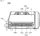
- FIG. 3 is a diagram schematically showing an electromagnetic induction heating cooking appliance according to an exemplary embodiment.
- FIG. 4 is a diagram showing the cooking appliance shown in FIG. 1 in use.
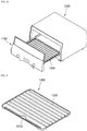
- FIG. 5 is a perspective view of a heating plate of the cooking appliance shown in FIG. 1 .
- a cooking appliance 1000 may include a door 1100, a main body 1200, and a heating plate 1300.
- the main body or body 1200 may include an electromagnetic induction heater 1210 that provides an induced current to the heating plate 1300, and also may include an infrared heat generator 1220 in order to heat food or a food container placed on the heating plate 1300 and accommodated in a cooking space S.
- the electromagnetic induction heater 1210 may be provided at a lower portion of the main body 1200 such that it generates heat in an upward direction.
- An infrared heat generator 1220 may be provided at an upper portion of the main body 1200.
- the door 1100 may be detachably coupled to the main body 1200 to open and close the cooking space S formed in the main body 1200.
- the heating plate 1300 may be coupled to the door 1100. When the door 1100 opens the cooking space, the heating plate 1300 may be drawn out of the cooking space S. When the door 1100 closes the cooking space S, the heating plate 1300 may be inserted into the cooking space S.
- the heating plate 1300 may be made of a magnetic material that is heated by an induced current.
- a water storage groove 1310 that may generate steam may be formed in the heating plate 1300.
- the heating plate 1300 may be provided with protrusions 1320 that form grill marks.
- the heating plate 1300 may be detachably coupled to the door 1100 so that it may be cleaned separately from the rest of the appliance.
- the electromagnetic induction heater 1210 may include a working coil 1211, a bottom board 1212, and a temperature sensor 1213.
- the working coil 1211 may provide an induced current to the heating plate 1300, and the heating plate 1300 may generate heat via the induced current provided by the working coil 1211.
- the bottom board 1212 may support the heating plate 1300 and may be made of a ceramic plate through which induced current may pass.
- the temperature sensor 1213 may measure a temperature of the heating plate 1300 and may contact a central portion of the heating plate 1300.
- a hole may be formed in the bottom board 1212, and the temperature sensor 1213 may be inserted into the hole to measure the temperature of the heating plate 1300.
- the temperature of the heating plate 1300 may be measured without contact by making a portion of the bottom board 1212 transparent and by using a non-contact temperature sensor.
- the electromagnetic induction heater 1210 may be provided at a lower portion of the main body 1200 such that it generates heat upwards.
- An infrared heat generator 1220 may be provided at an upper portion of the main body 1200.
- a reflection plate 1230 may be mounted at the upper portion of the main body 1200. The reflection plate 1230 may reflect heat emitted from the heating plate 1300 back to the food or a food container placed on the heating plate 1330.
- the electromagnetic induction heating cooking appliance 1000 may include the electromagnetic induction heater 1210 provided on or at one or a first side of the cooking space S and the infrared heat generator 1220 provided on or at another or a second side of the cooking space S, such that food placed on a heating plate 1300 can be cooked more efficiently and conveniently.
- the heating plate 1300 may be removed from the door 1100 such that it is easy to be maintained and cleaned. Moisture may be supplied when steam is generated from water stored in a water storage groove 1310 formed in the heating plate 1300.
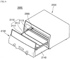
- FIG. 6 is a diagram schematically showing an oven cooking appliance according to an embodiment.
- FIG. 7 is a diagram illustrating a heating plate of the oven cooking appliance shown in FIG. 6 when a door is closed.
- FIG. 8 is a diagram illustrating the heating plate of the oven cooking appliance shown in FIG. 6 when the door is opened.
- a cooking appliance 2000 according to an embodiment may be identical to the cooking appliance 1000 shown in FIG. 1 , except in a location of the heating plate and in a configuration of the door.
- the cooking appliance 2000 may include a door 2100, a main body 2200, and a heating plate 2300.
- An electromagnetic induction heater 1210 (see FIG. 3 ) and an infrared heat generator 1220 (see FIG. 3 ) may be mounted on two sides of the main body 2200.
- a reflection plate 1230 (see FIG. 3 ) may be mounted on an upper portion of the main body 2200.
- the door 2100 may include a holding portion 2110.
- the holding portion 2110 may hold or store food or a food container. When the door 2100 opens the cooking space S of the main body 2200, the holding portion 2110 may be drawn out from the cooking space S. When the door 2100 closes the cooking space S, the holding portion 2110 may be inserted into the cooking space S and may come into contact with the heating plate 2300.
- the holding portion 2110 may include wires 2111, holding members 2112, and wheels 2113.
- the holding portion 2110 may be formed by coupling the wires 2111 to a pair of holding members 2112 facing each other, and by coupling wheels 2113 to both sides of the holding members 2112, respectively.
- the main body 2200 may include a guide frame 2210 that may guide movement of the holding portion 2110. In the guide frame 2210, seating grooves 2211 may be formed. Each of the wheels 2113 of the holding portion 2110 may be inserted into the seating grooves 2211.
- the seating grooves 2211 may be provided at a location corresponding to a location of each of the wheels 2113 when the door 2100 is drawn into the main body 2200 to cover the cooking space S, and may also correspond to the location of each of the wheels 2113 when the door 2100 is drawn out of the cooking appliance 2000 as far as possible.
- the holding portion 2110 may have a door coupling groove 2112a so that it can be detachably coupled with the door 2100.
- the door may have a coupling protrusion that fits into the door coupling groove 2111a.
- a water storage groove 2310 that may generate steam may be formed in the heating plate 2300, along with a wire insertion groove 2320 in which the wires 2111 are inserted.
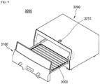
- FIG. 9 is a block diagram schematically showing a cooking appliance according to an embodiment.
- a cooking appliance according to this embodiment may be identical to the cooking appliance shown in FIG. 3 except that a water channel may be provided.
- the cooking appliance 3000 may include a door 3100, a main body 3200, and a heating plate 3300.
- An electromagnetic induction heater 1210 (see FIG. 3 ) and an infrared heat generator 1220 (see FIG. 3 ) may be mounted on two different sides of the main body 3200, respectively.
- a reflection plate 1230 (see FIG. 3 ) may be mounted on an upper portion of the main body 3200.
- the main body 3200 may include a water channel 3210.
- One or a first end of the water channel 3210 may be provided outside of the main body 3200.
- one or a first end of the water channel 3210 may be provided on top of the main body 3200.
- the other or a second end of the water channel 3210 may face a water storage groove 1310 (see FIG. 5 ) of the heating plate 3300 so that water may flow to the water storage groove 1310 when water is supplied to the water channel 3210.
- a user can generate steam by supplying water while the cooking appliance is operating.
- Embodiments disclosed herein provide an electromagnetic induction heating cooking appliance capable of improving heating efficiency and capable of shortening heating or cooking time by heating food accommodated in a cooking space part or cooking space from a top and bottom simultaneously.
- Embodiments disclosed herein provide an electromagnetic induction heating cooking appliance in which food or a food container may be conveniently placed into or taken out of a cooking chamber or cooking space.
- Embodiments disclosed herein provide an electromagnetic induction heating cooking appliance in which food may be heated more quickly and more efficiently with an infrared heater and an electromagnetic induction heating module or heater, thereby improving heat transfer.
- Embodiments disclosed herein provide an electromagnetic induction heating cooking appliance capable of generating steam at the time of heating without additional water supply by forming a water storage groove in the heating plate.
- Embodiments disclosed herein provide an electromagnetic induction heating cooking appliance that may be easily cleaned and conveniently used.
- a heating unit or heat emitter may be provided on one or a first side of a cooking space where a heating plate is accommodated, and an electromagnetic induction heating module or heater may be provided on another or a second side of the cooking space.
- Food or a food container placed on a heating plate may be thus efficiently heated from both sides or at least two different sides.
- the heating plate or the bottom board where food or a food container is placed may be coupled with a door. When the door opens or closes the cooking space of a main body, the heating plate or the bottom board may be drawn out of or into the cooking space, thereby allowing the food or the food container to be conveniently placed into or taken out of the cooking space.
- An infrared heater may be mounted on an upper portion of the cooking space in which food or a food container is accommodated, and an induction heating module or induction heater may be mounted on a lower portion of the cooking space. The food can therefore be heated quickly and efficiently.
- a water storage groove may be formed in the heating plate.
- the heating plate or the bottom board where food or a food container is placed may be coupled with the door.
- the heating plate is supported on the bottom board such that it is easy to clean the cooking appliance.
- food can be heated from both or multiple sides such that the food can be heated evenly, more efficiently, and more quickly, such that the heating time is reduced.
- food or a food container may be easily put into or taken out of a cooking chamber through a heating plate or a bottom board coupled to a door, thereby preventing contamination of the appliance.
- food can be heated quickly and efficiently with an infrared heater and an electromagnetic induction heating module or heater such that heat transfer can be improved. Further, steam may be supplied during heating without supplying water separately, such that moisture can be selectively supplied to the food that is heated. According to an exemplary embodiment, an electromagnetic induction heating cooking appliance may be easily cleaned and conveniently used.
- first, second, third, etc. may be used herein to describe various elements, components, regions, layers and/or sections, these elements, components, regions, layers and/or sections should not be limited by these terms. These terms are only used to distinguish one element, component, region, layer or section from another region, layer or section. Thus, a first element, component, region, layer or section could be termed a second element, component, region, layer or section without departing from the teachings of the present invention.
- spatially relative terms such as “lower”, “upper” and the like, may be used herein for ease of description to describe the relationship of one element or feature to another element(s) or feature(s) as illustrated in the figures. It will be understood that the spatially relative terms are intended to encompass different orientations of the device in use or operation, in addition to the orientation depicted in the figures. For example, if the device in the figures is turned over, elements described as “lower” relative to other elements or features would then be oriented “upper” relative the other elements or features. Thus, the exemplary term “lower” can encompass both an orientation of above and below. The device may be otherwise oriented (rotated 90 degrees or at other orientations) and the spatially relative descriptors used herein interpreted accordingly.
- Embodiments of the disclosure are described herein with reference to cross-section illustrations that are schematic illustrations of idealized embodiments (and intermediate structures) of the disclosure. As such, variations from the shapes of the illustrations as a result, for example, of manufacturing techniques and/or tolerances, are to be expected. Thus, embodiments of the disclosure should not be construed as limited to the particular shapes of regions illustrated herein but are to include deviations in shapes that result, for example, from manufacturing.
- any reference in this specification to "one embodiment,” “an embodiment,” “example embodiment,” etc. means that a particular feature, structure, or characteristic described in connection with the embodiment is included in at least one embodiment.
- the appearances of such phrases in various places in the specification are not necessarily all referring to the same embodiment.
Landscapes
- Engineering & Computer Science (AREA)
- Physics & Mathematics (AREA)
- Electromagnetism (AREA)
- Food Science & Technology (AREA)
- Chemical & Material Sciences (AREA)
- Combustion & Propulsion (AREA)
- Mechanical Engineering (AREA)
- General Engineering & Computer Science (AREA)
- Induction Heating Cooking Devices (AREA)
- Baking, Grill, Roasting (AREA)
Description
- An electromagnetic induction heating cooking appliance is disclosed herein.
- Typically, a cooking appliance is used to cook various foods or other items (hereinafter "food"), such as rice, soup, and stew, or to warm up food with heating devices. An electromagnetic induction heating cooking appliance is used to cook food by generating heat with an electromagnetic force. It utilizes the principle that when a metal is placed in a changing magnetic field, an eddy current is generated by electromagnetic induction, such that heat is generated in the metal by the current.
- Various products, such as a microwave oven using microwaves, a microwave oven using a heat generator, and a cooktop, for example, are widely used as cooking appliances. The microwave oven heats food using electromagnetic radiation, generated by a magnetron in a sealed cooking chamber, to vibrate water molecules in the food, thereby producing thermal energy. The oven uses a heater or heat generator to heat a sealed cooking chamber, thereby heating food contained therein.
- In existing cooking appliances, a heating unit or heater is disposed only on one side of a cooking space, and thus decreases heating efficiency. In addition, it is often necessary to change the orientation of food or flip it to ensure that all sides of the food is heated or cooked. In existing cooking appliances, a door is coupled with a main body via a hinge. It may therefore be difficult to put food or a food container into the cooking chamber of the cooking appliance without spilling the contents.
- In existing cooking appliances, food is heated with only one of either an infrared heater or by electromagnetic induction heating, such that heat cannot be transferred efficiently. Existing cooking appliances have no capability of supplying water on their own and thus cannot generate steam when heating food.
- An existing pop-up toaster is very difficult to clean. An existing oven type cooking appliance is also difficult to clean due to an infrared heat generator or infrared heater at its bottom.
- It is an object of the present disclosure to provide an electromagnetic induction heating cooking appliance capable of improving the heating efficiency and shortening the heating time by heating food accommodated in the cooking space part from the top and bottom simultaneously.
- It is another object of the present disclosure to provide an electromagnetic induction heating cooking appliance in which food or a food container can be conveniently put into or taken out of the cooking chamber.
- It is another object of the present disclosure to provide an electromagnetic induction heating cooking appliance in which food can be heated faster and more efficiently with an infrared heater and an electromagnetic induction heating module, thereby improving the heat transfer.
- It is yet another object of the present disclosure to provide an electromagnetic induction heating cooking appliance capable of generating steam at the time of heating without additional water supply by forming a water storage groove in the heating plate.
- It is still another object of the present disclosure to provide an electromagnetic induction heating cooking appliance that can be easily cleaned and conveniently used by a user.
- Objects of the present disclosure are not limited to the above-described objects and other objects and advantages can be appreciated by those skilled in the art from the following descriptions. Further, it will be easily appreciated that the objects and advantages of the present disclosure can be practiced by means recited in the appended claims and a combination thereof.
- In accordance with one aspect of the present disclosure, a heating unit is disposed on one side of a cooking space where a heating plate is accommodated, and an electromagnetic induction heating module is disposed on another side of the cooking space.
- Accordingly, food or a food container placed on a heating plate is efficiently heated from both sides.
- The heating plate or the bottom board where food or a food container is placed may be coupled with the door.
- Accordingly, when the door is moved to open or close the cooking space of the main body, the heating plate or the bottom board may be drawn out of the cooking space or into the cooking space, thereby allowing the food or the food container to be conveniently put into or taken out of the cooking space.
- An infrared heater may be mounted at the upper portion of the cooking space part in which food or a food container is accommodated, and an induction heating module may be mounted at the lower portion thereof. Accordingly, the food can be heated quickly and efficiently.
- A water storage groove may be formed in the heating plate. Thus, it is possible to provide steam at the time of heating.
- The heating plate or the bottom board where food or a food container is placed may be coupled with the door. The heating plate is supported on the bottom board. Accordingly, it is easy to clean the cooking appliance.
- According to an exemplary embodiment of the present disclosure, food can be heated from both sides, such that the food can be heated evenly, the heating efficiency can be increased, and the heating time can be saved.
- According to an exemplary embodiment of the present disclosure, food or a food container can be easily put into or taken out of the cooking chamber through the heating plate or the bottom board coupled to the door, thereby preventing contamination of the appliance due to the food.
- According to an exemplary embodiment of the present disclosure, food can be heated quickly and efficiently with an infrared heater and an electromagnetic induction heating module, and the heat transfer can be improved.
- Further, according to an exemplary embodiment of the present disclosure, steam can be supplied during heating without supplying water separately, such that moisture can be selectively supplied to the food to be heated.
- In addition, according to an exemplary embodiment of the present disclosure, an electromagnetic induction heating cooking appliance can be easily cleaned and conveniently used by a user.
- Embodiments will be described in detail with reference to the following drawings in which like reference numerals refer to like elements, and wherein:
-
FIG. 1 is a block diagram illustrating a cooking appliance according to an embodiment; -
FIG. 2 is a block diagram illustrating an electromagnetic induction heating cooking appliance as an example of the cooking appliance shown inFIG. 1 ; -
FIG. 3 is a diagram schematically showing an electromagnetic induction heating cooking appliance according to an exemplary embodiment; -
FIG. 4 is a diagram showing the cooking appliance shown inFIG. 1 in use; -
FIG. 5 is a perspective view of a heating plate of the cooking appliance shown inFIG. 1 ; -
FIG. 6 is a diagram schematically showing an oven cooking appliance according to an exemplary embodiment; -
FIG. 7 is a diagram illustrating a heating plate of the oven cooking appliance shown inFIG. 6 when a door is closed; -
FIG. 8 is a diagram illustrating the heating plate of the oven cooking appliance shown inFIG. 6 when the door is opened; and -
FIG. 9 is a block diagram schematically showing a cooking appliance according to an exemplary embodiment. -
FIG. 1 is a block diagram illustrating a cooking appliance according to an exemplary embodiment. As shown inFIG. 1 , a cooking appliance 100 may include afirst heater 110 provided on one or a first side of acooking space 130, and asecond heater 120 provided on another or a second side of thecooking space 130. As the two heaters are provided as described above, food placed in thecooking space 130 can be heated more efficiently. -
FIG. 2 is a block diagram illustrating an electromagnetic induction heating cooking appliance as an example of the cooking appliance shown inFIG. 1 . As shown inFIG. 2 , an electromagnetic inductionheating cooking appliance 200 may include a first heater, anelectromagnetic induction heater 210, provided on one or a first side of acooking space 230, and a second heater, aheat emitter 220, provided on another or a second side of thecooking space 230. Thecooking space 230 may include aheating plate 240 heated by an induced current from theelectromagnetic induction heater 210. Theheating plate 240 may include a magnetic substance. - The
electromagnetic induction heater 210 may include abottom board 211 that supports theheating plate 240. Thebottom board 211 may be a ceramic plate so that an induced current may pass therethrough. Theheat emitter 220 may include aheat generator 221 and areflection plate 222. Theheat generator 221 may produce heat to heat or cook food placed on theheating plate 240. Thereflection plate 222 may reflect the heat produced from theheating plate 240 back onto the food placed on theheating plate 240. -
FIG. 3 is a diagram schematically showing an electromagnetic induction heating cooking appliance according to an exemplary embodiment.FIG. 4 is a diagram showing the cooking appliance shown inFIG. 1 in use.FIG. 5 is a perspective view of a heating plate of the cooking appliance shown inFIG. 1 . As shown inFIG. 3 , acooking appliance 1000 may include adoor 1100, amain body 1200, and aheating plate 1300. - More specifically, the main body or
body 1200 may include anelectromagnetic induction heater 1210 that provides an induced current to theheating plate 1300, and also may include aninfrared heat generator 1220 in order to heat food or a food container placed on theheating plate 1300 and accommodated in a cooking space S. Theelectromagnetic induction heater 1210 may be provided at a lower portion of themain body 1200 such that it generates heat in an upward direction. Aninfrared heat generator 1220 may be provided at an upper portion of themain body 1200. - The
door 1100 may be detachably coupled to themain body 1200 to open and close the cooking space S formed in themain body 1200. Theheating plate 1300 may be coupled to thedoor 1100. When thedoor 1100 opens the cooking space, theheating plate 1300 may be drawn out of the cooking space S. When thedoor 1100 closes the cooking space S, theheating plate 1300 may be inserted into the cooking space S. - The
heating plate 1300 may be made of a magnetic material that is heated by an induced current. In addition, as shown inFIG. 5 , awater storage groove 1310 that may generate steam may be formed in theheating plate 1300. Further, theheating plate 1300 may be provided withprotrusions 1320 that form grill marks. Also, theheating plate 1300 may be detachably coupled to thedoor 1100 so that it may be cleaned separately from the rest of the appliance. Theelectromagnetic induction heater 1210 may include a workingcoil 1211, abottom board 1212, and atemperature sensor 1213. The workingcoil 1211 may provide an induced current to theheating plate 1300, and theheating plate 1300 may generate heat via the induced current provided by the workingcoil 1211. - The
bottom board 1212 may support theheating plate 1300 and may be made of a ceramic plate through which induced current may pass. In addition, thetemperature sensor 1213 may measure a temperature of theheating plate 1300 and may contact a central portion of theheating plate 1300. A hole may be formed in thebottom board 1212, and thetemperature sensor 1213 may be inserted into the hole to measure the temperature of theheating plate 1300. Alternatively, the temperature of theheating plate 1300 may be measured without contact by making a portion of thebottom board 1212 transparent and by using a non-contact temperature sensor. Theelectromagnetic induction heater 1210 may be provided at a lower portion of themain body 1200 such that it generates heat upwards. Aninfrared heat generator 1220 may be provided at an upper portion of themain body 1200. Areflection plate 1230 may be mounted at the upper portion of themain body 1200. Thereflection plate 1230 may reflect heat emitted from theheating plate 1300 back to the food or a food container placed on the heating plate 1330. - As described above, the electromagnetic induction
heating cooking appliance 1000 according to an embodiment may include theelectromagnetic induction heater 1210 provided on or at one or a first side of the cooking space S and theinfrared heat generator 1220 provided on or at another or a second side of the cooking space S, such that food placed on aheating plate 1300 can be cooked more efficiently and conveniently. Theheating plate 1300 may be removed from thedoor 1100 such that it is easy to be maintained and cleaned. Moisture may be supplied when steam is generated from water stored in awater storage groove 1310 formed in theheating plate 1300. -
FIG. 6 is a diagram schematically showing an oven cooking appliance according to an embodiment.FIG. 7 is a diagram illustrating a heating plate of the oven cooking appliance shown inFIG. 6 when a door is closed.FIG. 8 is a diagram illustrating the heating plate of the oven cooking appliance shown inFIG. 6 when the door is opened. Acooking appliance 2000 according to an embodiment may be identical to thecooking appliance 1000 shown inFIG. 1 , except in a location of the heating plate and in a configuration of the door. Thecooking appliance 2000 may include adoor 2100, amain body 2200, and aheating plate 2300. - An electromagnetic induction heater 1210 (see
FIG. 3 ) and an infrared heat generator 1220 (seeFIG. 3 ) may be mounted on two sides of themain body 2200. A reflection plate 1230 (seeFIG. 3 ) may be mounted on an upper portion of themain body 2200. Thedoor 2100 may include a holdingportion 2110. The holdingportion 2110 may hold or store food or a food container. When thedoor 2100 opens the cooking space S of themain body 2200, the holdingportion 2110 may be drawn out from the cooking space S. When thedoor 2100 closes the cooking space S, the holdingportion 2110 may be inserted into the cooking space S and may come into contact with theheating plate 2300. - The holding
portion 2110 may includewires 2111, holdingmembers 2112, andwheels 2113. The holdingportion 2110 may be formed by coupling thewires 2111 to a pair of holdingmembers 2112 facing each other, and bycoupling wheels 2113 to both sides of the holdingmembers 2112, respectively. Themain body 2200 may include aguide frame 2210 that may guide movement of the holdingportion 2110. In theguide frame 2210,seating grooves 2211 may be formed. Each of thewheels 2113 of the holdingportion 2110 may be inserted into theseating grooves 2211. - The
seating grooves 2211 may be provided at a location corresponding to a location of each of thewheels 2113 when thedoor 2100 is drawn into themain body 2200 to cover the cooking space S, and may also correspond to the location of each of thewheels 2113 when thedoor 2100 is drawn out of thecooking appliance 2000 as far as possible. The holdingportion 2110 may have a door coupling groove 2112a so that it can be detachably coupled with thedoor 2100. The door may have a coupling protrusion that fits into thedoor coupling groove 2111a. Awater storage groove 2310 that may generate steam may be formed in theheating plate 2300, along with awire insertion groove 2320 in which thewires 2111 are inserted. -
FIG. 9 is a block diagram schematically showing a cooking appliance according to an embodiment. As shown inFIG. 9 , a cooking appliance according to this embodiment may be identical to the cooking appliance shown inFIG. 3 except that a water channel may be provided. More specifically, thecooking appliance 3000 may include adoor 3100, amain body 3200, and aheating plate 3300. - An electromagnetic induction heater 1210 (see
FIG. 3 ) and an infrared heat generator 1220 (seeFIG. 3 ) may be mounted on two different sides of themain body 3200, respectively. A reflection plate 1230 (seeFIG. 3 ) may be mounted on an upper portion of themain body 3200. - The
main body 3200 may include awater channel 3210. One or a first end of thewater channel 3210 may be provided outside of themain body 3200. For example, one or a first end of thewater channel 3210 may be provided on top of themain body 3200. The other or a second end of thewater channel 3210 may face a water storage groove 1310 (seeFIG. 5 ) of theheating plate 3300 so that water may flow to thewater storage groove 1310 when water is supplied to thewater channel 3210. Thus, a user can generate steam by supplying water while the cooking appliance is operating. - Embodiments disclosed herein provide an electromagnetic induction heating cooking appliance capable of improving heating efficiency and capable of shortening heating or cooking time by heating food accommodated in a cooking space part or cooking space from a top and bottom simultaneously. Embodiments disclosed herein provide an electromagnetic induction heating cooking appliance in which food or a food container may be conveniently placed into or taken out of a cooking chamber or cooking space.
- Embodiments disclosed herein provide an electromagnetic induction heating cooking appliance in which food may be heated more quickly and more efficiently with an infrared heater and an electromagnetic induction heating module or heater, thereby improving heat transfer. Embodiments disclosed herein provide an electromagnetic induction heating cooking appliance capable of generating steam at the time of heating without additional water supply by forming a water storage groove in the heating plate. Embodiments disclosed herein provide an electromagnetic induction heating cooking appliance that may be easily cleaned and conveniently used.
- In accordance with an embodiment, a heating unit or heat emitter may be provided on one or a first side of a cooking space where a heating plate is accommodated, and an electromagnetic induction heating module or heater may be provided on another or a second side of the cooking space. Food or a food container placed on a heating plate may be thus efficiently heated from both sides or at least two different sides. The heating plate or the bottom board where food or a food container is placed may be coupled with a door. When the door opens or closes the cooking space of a main body, the heating plate or the bottom board may be drawn out of or into the cooking space, thereby allowing the food or the food container to be conveniently placed into or taken out of the cooking space. An infrared heater may be mounted on an upper portion of the cooking space in which food or a food container is accommodated, and an induction heating module or induction heater may be mounted on a lower portion of the cooking space. The food can therefore be heated quickly and efficiently.
- A water storage groove may be formed in the heating plate. Thus, it is possible to provide steam at the time of heating. The heating plate or the bottom board where food or a food container is placed may be coupled with the door. The heating plate is supported on the bottom board such that it is easy to clean the cooking appliance.
- According to an embodiment, food can be heated from both or multiple sides such that the food can be heated evenly, more efficiently, and more quickly, such that the heating time is reduced. According to an embodiment, food or a food container may be easily put into or taken out of a cooking chamber through a heating plate or a bottom board coupled to a door, thereby preventing contamination of the appliance.
- According to an embodiment, food can be heated quickly and efficiently with an infrared heater and an electromagnetic induction heating module or heater such that heat transfer can be improved. Further, steam may be supplied during heating without supplying water separately, such that moisture can be selectively supplied to the food that is heated. According to an exemplary embodiment, an electromagnetic induction heating cooking appliance may be easily cleaned and conveniently used.
- It will be understood that when an element or layer is referred to as being "on" another element or layer, the element or layer can be directly on another element or layer or intervening elements or layers. In contrast, when an element is referred to as being "directly on" another element or layer, there are no intervening elements or layers present. As used herein, the term "and/or" includes any and all combinations of one or more of the associated listed items.
- It will be understood that, although the terms first, second, third, etc., may be used herein to describe various elements, components, regions, layers and/or sections, these elements, components, regions, layers and/or sections should not be limited by these terms. These terms are only used to distinguish one element, component, region, layer or section from another region, layer or section. Thus, a first element, component, region, layer or section could be termed a second element, component, region, layer or section without departing from the teachings of the present invention.
- Spatially relative terms, such as "lower", "upper" and the like, may be used herein for ease of description to describe the relationship of one element or feature to another element(s) or feature(s) as illustrated in the figures. It will be understood that the spatially relative terms are intended to encompass different orientations of the device in use or operation, in addition to the orientation depicted in the figures. For example, if the device in the figures is turned over, elements described as "lower" relative to other elements or features would then be oriented "upper" relative the other elements or features. Thus, the exemplary term "lower" can encompass both an orientation of above and below. The device may be otherwise oriented (rotated 90 degrees or at other orientations) and the spatially relative descriptors used herein interpreted accordingly.
- The terminology used herein is for the purpose of describing particular embodiments only and is not intended to be limiting of the invention. As used herein, the singular forms "a", "an" and "the" are intended to include the plural forms as well, unless the context clearly indicates otherwise. It will be further understood that the terms "comprises" and/or "comprising," when used in this specification, specify the presence of stated features, integers, steps, operations, elements, and/or components, but do not preclude the presence or addition of one or more other features, integers, steps, operations, elements, components, and/or groups thereof.
- Embodiments of the disclosure are described herein with reference to cross-section illustrations that are schematic illustrations of idealized embodiments (and intermediate structures) of the disclosure. As such, variations from the shapes of the illustrations as a result, for example, of manufacturing techniques and/or tolerances, are to be expected. Thus, embodiments of the disclosure should not be construed as limited to the particular shapes of regions illustrated herein but are to include deviations in shapes that result, for example, from manufacturing.
- Unless otherwise defined, all terms (including technical and scientific terms) used herein have the same meaning as commonly understood by one of ordinary skill in the art to which this invention belongs. It will be further understood that terms, such as those defined in commonly used dictionaries, should be interpreted as having a meaning that is consistent with their meaning in the context of the relevant art and will not be interpreted in an idealized or overly formal sense unless expressly so defined herein.
- Any reference in this specification to "one embodiment," "an embodiment," "example embodiment," etc., means that a particular feature, structure, or characteristic described in connection with the embodiment is included in at least one embodiment. The appearances of such phrases in various places in the specification are not necessarily all referring to the same embodiment. Further, when a particular feature, structure, or characteristic is described in connection with any embodiment, it is submitted that it is within the purview of one skilled in the art to effect such feature, structure, or characteristic in connection with other ones of the embodiments.
- Although embodiments have been described with reference to a number of illustrative embodiments thereof, it should be understood that numerous other modifications and embodiments can be devised by those skilled in the art that will fall within the spirit and scope of the principles of this disclosure. More particularly, various variations and modifications are possible in the component parts and/or arrangements of the subject combination arrangement within the scope of the disclosure, the drawings and the appended claims. In addition to variations and modifications in the component parts and/or arrangements, alternative uses will also be apparent to those skilled in the art.
Claims (13)
- An electromagnetic induction heating cooking appliance, comprising:a heating plate comprising a magnetic substance;a cooking space in which the heating plate is accommodated;an electromagnetic induction heater that supplies an induced current to the heating plate; anda heat emitter that heats food placed on the heating plate, wherein the electromagnetic induction heater and the heat emitter are provided on different sides of the cooking space, respectively.
- The cooking appliance of claim 1, wherein the heat emitter comprises:a heat generator that emits heat toward the heating plate; anda reflection plate that reflects the heat emitted from the heating plate back to the heating plate.
- The cooking appliance of claim 1, wherein the electromagnetic induction heater comprises:a working coil that generates the induced current; anda bottom board that supports the heating plate and is provided between the working coil and the heating plate.
- The cooking appliance of claim 3, wherein the bottom board is a ceramic plate through which the induced current passes.
- The cooking appliance of claim 1, further comprising:a main body comprising the electromagnetic induction heater mounted on a first side, the heat emitter mounted on a second side, wherein the cooking space is formed in the main body; anda door that opens and closes the cooking space, wherein the door is detachably coupled with the main body and coupled with the heating plate such that the heating plate is drawn out of the cooking space when the door opens the cooking space, and is inserted into the cooking space when the door closes the cooking space.
- The cooking appliance of claim 5, wherein a water storage groove is provided in the heating plate such that water placed in the water storage groove turns into steam when it is heated.
- The cooking appliance of claim 6, wherein a water channel is provided in the main body, and wherein an end of the water channel faces the water storage groove such that water supplied from outside of the main body flows to the water storage groove.
- The cooking appliance of claim 5, wherein the electromagnetic induction heater further comprises a temperature sensor that measures a temperature of the heating plate, wherein an end of the temperature sensor is inserted into a hole formed in the bottom board, and comes in contact with the heating plate.
- The cooking appliance of claim 1, further comprising:a main body comprising the electromagnetic induction heater mounted on a first side and the heat emitter mounted on a second side and having the cooking space formed therein; anda door detachably coupled with the main body to open and close the cooking space, and further having a holding portion that holds food or a food container, wherein the holding portion is drawn out of the cooking space when the door opens, and is inserted into the cooking space when the door closes such that it is in contact with the heating plate.
- The cooking appliance of claim 9, wherein the holding portion comprises:wires on which the food or the food container are placed;holding members coupled with the wires; andwheels coupled to both sides of the holding members, respectively.
- The cooking appliance of claim 10, wherein the main body further comprises a guide frame that guides the holding portion, wherein the guide frame includes seating grooves in which the wheels of the holding portion are inserted, and wherein the seating grooves are formed on both ends of the guide frame with respect to a direction in which the wheels move.
- The cooking appliance of claim 9, wherein the holding members include door coupling grooves that detachably couple with the door, and wherein the door includes coupling protrusions that fit into the door coupling grooves, respectively.
- The cooking appliance of claim 9, wherein a water storage groove is provided in the heating plate to generate steam.
Applications Claiming Priority (2)
| Application Number | Priority Date | Filing Date | Title |
|---|---|---|---|
| KR1020170064858A KR101985528B1 (en) | 2017-05-25 | 2017-05-25 | Electromagnetic induction heating cooker |
| PCT/KR2017/009887 WO2018216856A1 (en) | 2017-05-25 | 2017-09-08 | Electromagnetic induction heating cooker |
Publications (3)
| Publication Number | Publication Date |
|---|---|
| EP3634087A1 true EP3634087A1 (en) | 2020-04-08 |
| EP3634087A4 EP3634087A4 (en) | 2021-02-24 |
| EP3634087B1 EP3634087B1 (en) | 2022-03-16 |
Family
ID=64396658
Family Applications (1)
| Application Number | Title | Priority Date | Filing Date |
|---|---|---|---|
| EP17911094.5A Active EP3634087B1 (en) | 2017-05-25 | 2017-09-08 | Electromagnetic induction heating cooker |
Country Status (5)
| Country | Link |
|---|---|
| US (1) | US10788218B2 (en) |
| EP (1) | EP3634087B1 (en) |
| KR (1) | KR101985528B1 (en) |
| CN (1) | CN211982171U (en) |
| WO (1) | WO2018216856A1 (en) |
Families Citing this family (10)
| Publication number | Priority date | Publication date | Assignee | Title |
|---|---|---|---|---|
| TWI630847B (en) * | 2016-02-25 | 2018-07-21 | 日商松下知識產權經營股份有限公司 | Induction heating conditioner |
| USD913747S1 (en) * | 2018-03-19 | 2021-03-23 | Traeger Pellet Grills, Llc | Barbecue smoker front panel |
| US11402102B2 (en) | 2019-09-30 | 2022-08-02 | Midea Group Co., Ltd. | User-configurable two-step activation sequence for gas cooktop burner |
| US11255460B2 (en) | 2019-09-30 | 2022-02-22 | Midea Group Co., Ltd. | Two-step turn on for digital gas valves |
| CN112674614B (en) * | 2019-10-18 | 2022-12-09 | 广东美的白色家电技术创新中心有限公司 | Cooking utensil |
| EP4018784B1 (en) | 2020-01-17 | 2025-10-01 | Samsung Electronics Co., Ltd. | Cooking appliance |
| KR102803127B1 (en) * | 2020-01-17 | 2025-05-08 | 삼성전자주식회사 | Cooking apparatus |
| CN111543847B (en) * | 2020-05-28 | 2021-07-16 | 宁波方太厨具有限公司 | Cooking device with steaming function |
| USD1000206S1 (en) | 2021-03-05 | 2023-10-03 | Tramontina Teec S.A. | Cooktop or portion thereof |
| USD1000205S1 (en) | 2021-03-05 | 2023-10-03 | Tramontina Teec S.A. | Cooktop or portion thereof |
Family Cites Families (12)
| Publication number | Priority date | Publication date | Assignee | Title |
|---|---|---|---|---|
| JPS5971930A (en) | 1983-09-01 | 1984-04-23 | Matsushita Electric Ind Co Ltd | Electric cooking apparatus |
| EP0266134A1 (en) * | 1986-10-29 | 1988-05-04 | THORN EMI Patents Limited | Apparatus for grilling or browning food |
| JP3796856B2 (en) * | 1996-11-01 | 2006-07-12 | 松下電器産業株式会社 | High frequency heating device |
| JP3732200B2 (en) * | 2004-01-07 | 2006-01-05 | シャープ株式会社 | Cooker |
| ES2330496B1 (en) * | 2007-10-31 | 2010-09-08 | Bsh Electrodomesticos España, S.A. | COOKING DEVICE. |
| JP5345122B2 (en) * | 2010-11-08 | 2013-11-20 | 三菱電機株式会社 | Induction heating cooker |
| JP5887234B2 (en) * | 2012-09-12 | 2016-03-16 | 日立アプライアンス株式会社 | Induction heating cooker |
| JP6101649B2 (en) * | 2014-02-27 | 2017-03-22 | 日立アプライアンス株式会社 | Induction heating cooker |
| JP2016207400A (en) * | 2015-04-21 | 2016-12-08 | 日立アプライアンス株式会社 | Induction heating cooker |
| AU2015411672B2 (en) * | 2015-10-16 | 2019-02-07 | Mitsubishi Electric Corporation | Heating cooker system, inductive heating cooker, and electric apparatus |
| TW201731430A (en) * | 2016-02-25 | 2017-09-16 | Panasonic Ip Man Co Ltd | Induction heating cooker and grill tray |
| JP6289602B2 (en) * | 2016-12-28 | 2018-03-07 | 三菱電機株式会社 | Cooker |
-
2017
- 2017-05-25 KR KR1020170064858A patent/KR101985528B1/en active Active
- 2017-09-08 EP EP17911094.5A patent/EP3634087B1/en active Active
- 2017-09-08 CN CN201790001716.0U patent/CN211982171U/en active Active
- 2017-09-08 WO PCT/KR2017/009887 patent/WO2018216856A1/en not_active Ceased
-
2018
- 2018-05-25 US US15/989,375 patent/US10788218B2/en active Active
Also Published As
| Publication number | Publication date |
|---|---|
| EP3634087B1 (en) | 2022-03-16 |
| KR20180129197A (en) | 2018-12-05 |
| EP3634087A4 (en) | 2021-02-24 |
| KR101985528B1 (en) | 2019-06-03 |
| US20180340692A1 (en) | 2018-11-29 |
| US10788218B2 (en) | 2020-09-29 |
| WO2018216856A1 (en) | 2018-11-29 |
| CN211982171U (en) | 2020-11-20 |
Similar Documents
| Publication | Publication Date | Title |
|---|---|---|
| US10788218B2 (en) | Electromagnetic induction heating cooking appliance | |
| US20240373516A1 (en) | Cooking appliance | |
| US11064578B2 (en) | Electromagnetic induction heating cooking appliance | |
| JP5322831B2 (en) | Induction heating cooker | |
| US10094576B2 (en) | Cooking appliance | |
| CN103988577A (en) | Induction cooking apparatus | |
| KR101935493B1 (en) | Electromagnetic induction heating cooker | |
| KR102232819B1 (en) | Electromagnetic induction heating cooker | |
| JP2014216114A (en) | Induction heating cooker | |
| KR102550654B1 (en) | Cooking Apparatus | |
| CN207561724U (en) | Split cooking apparatus | |
| KR101331602B1 (en) | Electric cooking apparatus | |
| KR102266355B1 (en) | Electromagnetic induction heating cooker | |
| KR20150079468A (en) | Cook top for cooking vessel | |
| KR100707426B1 (en) | Electric oven with vessel heating heater | |
| US20120132645A1 (en) | Induction heater | |
| KR200157113Y1 (en) | Grill Grills for Microwave | |
| JP5645606B2 (en) | Induction heating cooker | |
| JP2012094423A (en) | Induction heating cooker | |
| KR20100083089A (en) | Cooking apparatus and heating device thereof | |
| KR20190018944A (en) | Heating device and cooking appliance | |
| KR19990000738U (en) | Grill Grills for Microwave Ovens | |
| KR20100101347A (en) | A cooker |
Legal Events
| Date | Code | Title | Description |
|---|---|---|---|
| STAA | Information on the status of an ep patent application or granted ep patent |
Free format text: STATUS: THE INTERNATIONAL PUBLICATION HAS BEEN MADE |
|
| PUAI | Public reference made under article 153(3) epc to a published international application that has entered the european phase |
Free format text: ORIGINAL CODE: 0009012 |
|
| STAA | Information on the status of an ep patent application or granted ep patent |
Free format text: STATUS: REQUEST FOR EXAMINATION WAS MADE |
|
| 17P | Request for examination filed |
Effective date: 20191219 |
|
| AK | Designated contracting states |
Kind code of ref document: A1 Designated state(s): AL AT BE BG CH CY CZ DE DK EE ES FI FR GB GR HR HU IE IS IT LI LT LU LV MC MK MT NL NO PL PT RO RS SE SI SK SM TR |
|
| AX | Request for extension of the european patent |
Extension state: BA ME |
|
| DAV | Request for validation of the european patent (deleted) | ||
| DAX | Request for extension of the european patent (deleted) | ||
| A4 | Supplementary search report drawn up and despatched |
Effective date: 20210125 |
|
| RIC1 | Information provided on ipc code assigned before grant |
Ipc: H05B 6/06 20060101ALI20210119BHEP Ipc: A47J 37/06 20060101ALI20210119BHEP Ipc: H05B 6/36 20060101ALI20210119BHEP Ipc: H05B 6/12 20060101AFI20210119BHEP |
|
| GRAP | Despatch of communication of intention to grant a patent |
Free format text: ORIGINAL CODE: EPIDOSNIGR1 |
|
| STAA | Information on the status of an ep patent application or granted ep patent |
Free format text: STATUS: GRANT OF PATENT IS INTENDED |
|
| INTG | Intention to grant announced |
Effective date: 20211007 |
|
| GRAS | Grant fee paid |
Free format text: ORIGINAL CODE: EPIDOSNIGR3 |
|
| GRAA | (expected) grant |
Free format text: ORIGINAL CODE: 0009210 |
|
| STAA | Information on the status of an ep patent application or granted ep patent |
Free format text: STATUS: THE PATENT HAS BEEN GRANTED |
|
| AK | Designated contracting states |
Kind code of ref document: B1 Designated state(s): AL AT BE BG CH CY CZ DE DK EE ES FI FR GB GR HR HU IE IS IT LI LT LU LV MC MK MT NL NO PL PT RO RS SE SI SK SM TR |
|
| REG | Reference to a national code |
Ref country code: GB Ref legal event code: FG4D |
|
| REG | Reference to a national code |
Ref country code: CH Ref legal event code: EP Ref country code: DE Ref legal event code: R096 Ref document number: 602017054825 Country of ref document: DE |
|
| REG | Reference to a national code |
Ref country code: IE Ref legal event code: FG4D |
|
| REG | Reference to a national code |
Ref country code: AT Ref legal event code: REF Ref document number: 1476787 Country of ref document: AT Kind code of ref document: T Effective date: 20220415 |
|
| REG | Reference to a national code |
Ref country code: LT Ref legal event code: MG9D |
|
| REG | Reference to a national code |
Ref country code: NL Ref legal event code: MP Effective date: 20220316 |
|
| PG25 | Lapsed in a contracting state [announced via postgrant information from national office to epo] |
Ref country code: SE Free format text: LAPSE BECAUSE OF FAILURE TO SUBMIT A TRANSLATION OF THE DESCRIPTION OR TO PAY THE FEE WITHIN THE PRESCRIBED TIME-LIMIT Effective date: 20220316 Ref country code: RS Free format text: LAPSE BECAUSE OF FAILURE TO SUBMIT A TRANSLATION OF THE DESCRIPTION OR TO PAY THE FEE WITHIN THE PRESCRIBED TIME-LIMIT Effective date: 20220316 Ref country code: NO Free format text: LAPSE BECAUSE OF FAILURE TO SUBMIT A TRANSLATION OF THE DESCRIPTION OR TO PAY THE FEE WITHIN THE PRESCRIBED TIME-LIMIT Effective date: 20220616 Ref country code: LT Free format text: LAPSE BECAUSE OF FAILURE TO SUBMIT A TRANSLATION OF THE DESCRIPTION OR TO PAY THE FEE WITHIN THE PRESCRIBED TIME-LIMIT Effective date: 20220316 Ref country code: HR Free format text: LAPSE BECAUSE OF FAILURE TO SUBMIT A TRANSLATION OF THE DESCRIPTION OR TO PAY THE FEE WITHIN THE PRESCRIBED TIME-LIMIT Effective date: 20220316 Ref country code: BG Free format text: LAPSE BECAUSE OF FAILURE TO SUBMIT A TRANSLATION OF THE DESCRIPTION OR TO PAY THE FEE WITHIN THE PRESCRIBED TIME-LIMIT Effective date: 20220616 |
|
| REG | Reference to a national code |
Ref country code: AT Ref legal event code: MK05 Ref document number: 1476787 Country of ref document: AT Kind code of ref document: T Effective date: 20220316 |
|
| PG25 | Lapsed in a contracting state [announced via postgrant information from national office to epo] |
Ref country code: LV Free format text: LAPSE BECAUSE OF FAILURE TO SUBMIT A TRANSLATION OF THE DESCRIPTION OR TO PAY THE FEE WITHIN THE PRESCRIBED TIME-LIMIT Effective date: 20220316 Ref country code: GR Free format text: LAPSE BECAUSE OF FAILURE TO SUBMIT A TRANSLATION OF THE DESCRIPTION OR TO PAY THE FEE WITHIN THE PRESCRIBED TIME-LIMIT Effective date: 20220617 Ref country code: FI Free format text: LAPSE BECAUSE OF FAILURE TO SUBMIT A TRANSLATION OF THE DESCRIPTION OR TO PAY THE FEE WITHIN THE PRESCRIBED TIME-LIMIT Effective date: 20220316 |
|
| PG25 | Lapsed in a contracting state [announced via postgrant information from national office to epo] |
Ref country code: NL Free format text: LAPSE BECAUSE OF FAILURE TO SUBMIT A TRANSLATION OF THE DESCRIPTION OR TO PAY THE FEE WITHIN THE PRESCRIBED TIME-LIMIT Effective date: 20220316 |
|
| PG25 | Lapsed in a contracting state [announced via postgrant information from national office to epo] |
Ref country code: SM Free format text: LAPSE BECAUSE OF FAILURE TO SUBMIT A TRANSLATION OF THE DESCRIPTION OR TO PAY THE FEE WITHIN THE PRESCRIBED TIME-LIMIT Effective date: 20220316 Ref country code: SK Free format text: LAPSE BECAUSE OF FAILURE TO SUBMIT A TRANSLATION OF THE DESCRIPTION OR TO PAY THE FEE WITHIN THE PRESCRIBED TIME-LIMIT Effective date: 20220316 Ref country code: RO Free format text: LAPSE BECAUSE OF FAILURE TO SUBMIT A TRANSLATION OF THE DESCRIPTION OR TO PAY THE FEE WITHIN THE PRESCRIBED TIME-LIMIT Effective date: 20220316 Ref country code: PT Free format text: LAPSE BECAUSE OF FAILURE TO SUBMIT A TRANSLATION OF THE DESCRIPTION OR TO PAY THE FEE WITHIN THE PRESCRIBED TIME-LIMIT Effective date: 20220718 Ref country code: ES Free format text: LAPSE BECAUSE OF FAILURE TO SUBMIT A TRANSLATION OF THE DESCRIPTION OR TO PAY THE FEE WITHIN THE PRESCRIBED TIME-LIMIT Effective date: 20220316 Ref country code: EE Free format text: LAPSE BECAUSE OF FAILURE TO SUBMIT A TRANSLATION OF THE DESCRIPTION OR TO PAY THE FEE WITHIN THE PRESCRIBED TIME-LIMIT Effective date: 20220316 Ref country code: CZ Free format text: LAPSE BECAUSE OF FAILURE TO SUBMIT A TRANSLATION OF THE DESCRIPTION OR TO PAY THE FEE WITHIN THE PRESCRIBED TIME-LIMIT Effective date: 20220316 Ref country code: AT Free format text: LAPSE BECAUSE OF FAILURE TO SUBMIT A TRANSLATION OF THE DESCRIPTION OR TO PAY THE FEE WITHIN THE PRESCRIBED TIME-LIMIT Effective date: 20220316 |
|
| PG25 | Lapsed in a contracting state [announced via postgrant information from national office to epo] |
Ref country code: PL Free format text: LAPSE BECAUSE OF FAILURE TO SUBMIT A TRANSLATION OF THE DESCRIPTION OR TO PAY THE FEE WITHIN THE PRESCRIBED TIME-LIMIT Effective date: 20220316 Ref country code: IS Free format text: LAPSE BECAUSE OF FAILURE TO SUBMIT A TRANSLATION OF THE DESCRIPTION OR TO PAY THE FEE WITHIN THE PRESCRIBED TIME-LIMIT Effective date: 20220716 Ref country code: AL Free format text: LAPSE BECAUSE OF FAILURE TO SUBMIT A TRANSLATION OF THE DESCRIPTION OR TO PAY THE FEE WITHIN THE PRESCRIBED TIME-LIMIT Effective date: 20220316 |
|
| REG | Reference to a national code |
Ref country code: DE Ref legal event code: R097 Ref document number: 602017054825 Country of ref document: DE |
|
| PLBE | No opposition filed within time limit |
Free format text: ORIGINAL CODE: 0009261 |
|
| STAA | Information on the status of an ep patent application or granted ep patent |
Free format text: STATUS: NO OPPOSITION FILED WITHIN TIME LIMIT |
|
| PG25 | Lapsed in a contracting state [announced via postgrant information from national office to epo] |
Ref country code: DK Free format text: LAPSE BECAUSE OF FAILURE TO SUBMIT A TRANSLATION OF THE DESCRIPTION OR TO PAY THE FEE WITHIN THE PRESCRIBED TIME-LIMIT Effective date: 20220316 |
|
| 26N | No opposition filed |
Effective date: 20221219 |
|
| PG25 | Lapsed in a contracting state [announced via postgrant information from national office to epo] |
Ref country code: SI Free format text: LAPSE BECAUSE OF FAILURE TO SUBMIT A TRANSLATION OF THE DESCRIPTION OR TO PAY THE FEE WITHIN THE PRESCRIBED TIME-LIMIT Effective date: 20220316 |
|
| PG25 | Lapsed in a contracting state [announced via postgrant information from national office to epo] |
Ref country code: MC Free format text: LAPSE BECAUSE OF FAILURE TO SUBMIT A TRANSLATION OF THE DESCRIPTION OR TO PAY THE FEE WITHIN THE PRESCRIBED TIME-LIMIT Effective date: 20220316 |
|
| REG | Reference to a national code |
Ref country code: CH Ref legal event code: PL |
|
| GBPC | Gb: european patent ceased through non-payment of renewal fee |
Effective date: 20220908 |
|
| REG | Reference to a national code |
Ref country code: BE Ref legal event code: MM Effective date: 20220930 |
|
| PG25 | Lapsed in a contracting state [announced via postgrant information from national office to epo] |
Ref country code: LU Free format text: LAPSE BECAUSE OF NON-PAYMENT OF DUE FEES Effective date: 20220908 |
|
| PG25 | Lapsed in a contracting state [announced via postgrant information from national office to epo] |
Ref country code: LI Free format text: LAPSE BECAUSE OF NON-PAYMENT OF DUE FEES Effective date: 20220930 Ref country code: IT Free format text: LAPSE BECAUSE OF FAILURE TO SUBMIT A TRANSLATION OF THE DESCRIPTION OR TO PAY THE FEE WITHIN THE PRESCRIBED TIME-LIMIT Effective date: 20220316 Ref country code: IE Free format text: LAPSE BECAUSE OF NON-PAYMENT OF DUE FEES Effective date: 20220908 Ref country code: FR Free format text: LAPSE BECAUSE OF NON-PAYMENT OF DUE FEES Effective date: 20220930 Ref country code: CH Free format text: LAPSE BECAUSE OF NON-PAYMENT OF DUE FEES Effective date: 20220930 |
|
| PG25 | Lapsed in a contracting state [announced via postgrant information from national office to epo] |
Ref country code: BE Free format text: LAPSE BECAUSE OF NON-PAYMENT OF DUE FEES Effective date: 20220930 |
|
| PG25 | Lapsed in a contracting state [announced via postgrant information from national office to epo] |
Ref country code: GB Free format text: LAPSE BECAUSE OF NON-PAYMENT OF DUE FEES Effective date: 20220908 |
|
| PG25 | Lapsed in a contracting state [announced via postgrant information from national office to epo] |
Ref country code: HU Free format text: LAPSE BECAUSE OF FAILURE TO SUBMIT A TRANSLATION OF THE DESCRIPTION OR TO PAY THE FEE WITHIN THE PRESCRIBED TIME-LIMIT; INVALID AB INITIO Effective date: 20170908 |
|
| PG25 | Lapsed in a contracting state [announced via postgrant information from national office to epo] |
Ref country code: CY Free format text: LAPSE BECAUSE OF FAILURE TO SUBMIT A TRANSLATION OF THE DESCRIPTION OR TO PAY THE FEE WITHIN THE PRESCRIBED TIME-LIMIT Effective date: 20220316 |
|
| PG25 | Lapsed in a contracting state [announced via postgrant information from national office to epo] |
Ref country code: MK Free format text: LAPSE BECAUSE OF FAILURE TO SUBMIT A TRANSLATION OF THE DESCRIPTION OR TO PAY THE FEE WITHIN THE PRESCRIBED TIME-LIMIT Effective date: 20220316 |
|
| PG25 | Lapsed in a contracting state [announced via postgrant information from national office to epo] |
Ref country code: TR Free format text: LAPSE BECAUSE OF FAILURE TO SUBMIT A TRANSLATION OF THE DESCRIPTION OR TO PAY THE FEE WITHIN THE PRESCRIBED TIME-LIMIT Effective date: 20220316 |
|
| PG25 | Lapsed in a contracting state [announced via postgrant information from national office to epo] |
Ref country code: MT Free format text: LAPSE BECAUSE OF FAILURE TO SUBMIT A TRANSLATION OF THE DESCRIPTION OR TO PAY THE FEE WITHIN THE PRESCRIBED TIME-LIMIT Effective date: 20220316 |
|
| PGFP | Annual fee paid to national office [announced via postgrant information from national office to epo] |
Ref country code: DE Payment date: 20250805 Year of fee payment: 9 |