EP3633817A1 - Procédé de vérification d'un point de séparation d'un onduleur photovoltaïque et un tel onduleur photovoltaïque - Google Patents
Procédé de vérification d'un point de séparation d'un onduleur photovoltaïque et un tel onduleur photovoltaïque Download PDFInfo
- Publication number
- EP3633817A1 EP3633817A1 EP18198509.4A EP18198509A EP3633817A1 EP 3633817 A1 EP3633817 A1 EP 3633817A1 EP 18198509 A EP18198509 A EP 18198509A EP 3633817 A1 EP3633817 A1 EP 3633817A1
- Authority
- EP
- European Patent Office
- Prior art keywords
- point
- switching
- voltages
- phase
- output
- Prior art date
- Legal status (The legal status is an assumption and is not a legal conclusion. Google has not performed a legal analysis and makes no representation as to the accuracy of the status listed.)
- Withdrawn
Links
- 238000012360 testing method Methods 0.000 title claims abstract description 38
- 238000000034 method Methods 0.000 title claims abstract description 26
- 238000000926 separation method Methods 0.000 claims abstract description 64
- 239000004020 conductor Substances 0.000 claims description 71
- 230000007935 neutral effect Effects 0.000 claims description 70
- 238000011156 evaluation Methods 0.000 claims description 12
- 239000003990 capacitor Substances 0.000 claims description 11
- 230000008878 coupling Effects 0.000 claims description 8
- 238000010168 coupling process Methods 0.000 claims description 8
- 238000005859 coupling reaction Methods 0.000 claims description 8
- 230000005405 multipole Effects 0.000 claims description 6
- 238000005259 measurement Methods 0.000 claims description 4
- 238000002955 isolation Methods 0.000 claims description 3
- 238000010998 test method Methods 0.000 description 7
- 238000012935 Averaging Methods 0.000 description 3
- 230000005540 biological transmission Effects 0.000 description 2
- 230000003213 activating effect Effects 0.000 description 1
- 230000000712 assembly Effects 0.000 description 1
- 238000000429 assembly Methods 0.000 description 1
- 238000010276 construction Methods 0.000 description 1
- 230000006378 damage Effects 0.000 description 1
- 238000001514 detection method Methods 0.000 description 1
- 238000010586 diagram Methods 0.000 description 1
- 238000012544 monitoring process Methods 0.000 description 1
- 230000003071 parasitic effect Effects 0.000 description 1
- 230000001105 regulatory effect Effects 0.000 description 1
- 230000001960 triggered effect Effects 0.000 description 1
Images


Classifications
-
- G—PHYSICS
- G01—MEASURING; TESTING
- G01R—MEASURING ELECTRIC VARIABLES; MEASURING MAGNETIC VARIABLES
- G01R31/00—Arrangements for testing electric properties; Arrangements for locating electric faults; Arrangements for electrical testing characterised by what is being tested not provided for elsewhere
- G01R31/005—Testing of electric installations on transport means
- G01R31/006—Testing of electric installations on transport means on road vehicles, e.g. automobiles or trucks
-
- G—PHYSICS
- G01—MEASURING; TESTING
- G01R—MEASURING ELECTRIC VARIABLES; MEASURING MAGNETIC VARIABLES
- G01R31/00—Arrangements for testing electric properties; Arrangements for locating electric faults; Arrangements for electrical testing characterised by what is being tested not provided for elsewhere
- G01R31/327—Testing of circuit interrupters, switches or circuit-breakers
- G01R31/3271—Testing of circuit interrupters, switches or circuit-breakers of high voltage or medium voltage devices
- G01R31/3272—Apparatus, systems or circuits therefor
- G01R31/3274—Details related to measuring, e.g. sensing, displaying or computing; Measuring of variables related to the contact pieces, e.g. wear, position or resistance
-
- G—PHYSICS
- G01—MEASURING; TESTING
- G01R—MEASURING ELECTRIC VARIABLES; MEASURING MAGNETIC VARIABLES
- G01R31/00—Arrangements for testing electric properties; Arrangements for locating electric faults; Arrangements for electrical testing characterised by what is being tested not provided for elsewhere
- G01R31/327—Testing of circuit interrupters, switches or circuit-breakers
- G01R31/3271—Testing of circuit interrupters, switches or circuit-breakers of high voltage or medium voltage devices
- G01R31/3275—Fault detection or status indication
-
- G—PHYSICS
- G01—MEASURING; TESTING
- G01R—MEASURING ELECTRIC VARIABLES; MEASURING MAGNETIC VARIABLES
- G01R31/00—Arrangements for testing electric properties; Arrangements for locating electric faults; Arrangements for electrical testing characterised by what is being tested not provided for elsewhere
- G01R31/327—Testing of circuit interrupters, switches or circuit-breakers
- G01R31/3277—Testing of circuit interrupters, switches or circuit-breakers of low voltage devices, e.g. domestic or industrial devices, such as motor protections, relays, rotation switches
- G01R31/3278—Testing of circuit interrupters, switches or circuit-breakers of low voltage devices, e.g. domestic or industrial devices, such as motor protections, relays, rotation switches of relays, solenoids or reed switches
-
- G—PHYSICS
- G01—MEASURING; TESTING
- G01R—MEASURING ELECTRIC VARIABLES; MEASURING MAGNETIC VARIABLES
- G01R31/00—Arrangements for testing electric properties; Arrangements for locating electric faults; Arrangements for electrical testing characterised by what is being tested not provided for elsewhere
- G01R31/40—Testing power supplies
- G01R31/42—AC power supplies
-
- H—ELECTRICITY
- H01—ELECTRIC ELEMENTS
- H01H—ELECTRIC SWITCHES; RELAYS; SELECTORS; EMERGENCY PROTECTIVE DEVICES
- H01H47/00—Circuit arrangements not adapted to a particular application of the relay and designed to obtain desired operating characteristics or to provide energising current
- H01H47/002—Monitoring or fail-safe circuits
-
- H—ELECTRICITY
- H02—GENERATION; CONVERSION OR DISTRIBUTION OF ELECTRIC POWER
- H02J—CIRCUIT ARRANGEMENTS OR SYSTEMS FOR SUPPLYING OR DISTRIBUTING ELECTRIC POWER; SYSTEMS FOR STORING ELECTRIC ENERGY
- H02J3/00—Circuit arrangements for ac mains or ac distribution networks
- H02J3/38—Arrangements for parallely feeding a single network by two or more generators, converters or transformers
- H02J3/381—Dispersed generators
-
- H—ELECTRICITY
- H02—GENERATION; CONVERSION OR DISTRIBUTION OF ELECTRIC POWER
- H02S—GENERATION OF ELECTRIC POWER BY CONVERSION OF INFRARED RADIATION, VISIBLE LIGHT OR ULTRAVIOLET LIGHT, e.g. USING PHOTOVOLTAIC [PV] MODULES
- H02S40/00—Components or accessories in combination with PV modules, not provided for in groups H02S10/00 - H02S30/00
- H02S40/30—Electrical components
- H02S40/32—Electrical components comprising DC/AC inverter means associated with the PV module itself, e.g. AC modules
-
- H—ELECTRICITY
- H02—GENERATION; CONVERSION OR DISTRIBUTION OF ELECTRIC POWER
- H02S—GENERATION OF ELECTRIC POWER BY CONVERSION OF INFRARED RADIATION, VISIBLE LIGHT OR ULTRAVIOLET LIGHT, e.g. USING PHOTOVOLTAIC [PV] MODULES
- H02S50/00—Monitoring or testing of PV systems, e.g. load balancing or fault identification
-
- H—ELECTRICITY
- H01—ELECTRIC ELEMENTS
- H01H—ELECTRIC SWITCHES; RELAYS; SELECTORS; EMERGENCY PROTECTIVE DEVICES
- H01H11/00—Apparatus or processes specially adapted for the manufacture of electric switches
- H01H11/0062—Testing or measuring non-electrical properties of switches, e.g. contact velocity
-
- H—ELECTRICITY
- H02—GENERATION; CONVERSION OR DISTRIBUTION OF ELECTRIC POWER
- H02J—CIRCUIT ARRANGEMENTS OR SYSTEMS FOR SUPPLYING OR DISTRIBUTING ELECTRIC POWER; SYSTEMS FOR STORING ELECTRIC ENERGY
- H02J2300/00—Systems for supplying or distributing electric power characterised by decentralized, dispersed, or local generation
- H02J2300/20—The dispersed energy generation being of renewable origin
- H02J2300/22—The renewable source being solar energy
- H02J2300/24—The renewable source being solar energy of photovoltaic origin
-
- H—ELECTRICITY
- H02—GENERATION; CONVERSION OR DISTRIBUTION OF ELECTRIC POWER
- H02M—APPARATUS FOR CONVERSION BETWEEN AC AND AC, BETWEEN AC AND DC, OR BETWEEN DC AND DC, AND FOR USE WITH MAINS OR SIMILAR POWER SUPPLY SYSTEMS; CONVERSION OF DC OR AC INPUT POWER INTO SURGE OUTPUT POWER; CONTROL OR REGULATION THEREOF
- H02M1/00—Details of apparatus for conversion
- H02M1/32—Means for protecting converters other than automatic disconnection
-
- Y—GENERAL TAGGING OF NEW TECHNOLOGICAL DEVELOPMENTS; GENERAL TAGGING OF CROSS-SECTIONAL TECHNOLOGIES SPANNING OVER SEVERAL SECTIONS OF THE IPC; TECHNICAL SUBJECTS COVERED BY FORMER USPC CROSS-REFERENCE ART COLLECTIONS [XRACs] AND DIGESTS
- Y02—TECHNOLOGIES OR APPLICATIONS FOR MITIGATION OR ADAPTATION AGAINST CLIMATE CHANGE
- Y02E—REDUCTION OF GREENHOUSE GAS [GHG] EMISSIONS, RELATED TO ENERGY GENERATION, TRANSMISSION OR DISTRIBUTION
- Y02E10/00—Energy generation through renewable energy sources
- Y02E10/50—Photovoltaic [PV] energy
- Y02E10/56—Power conversion systems, e.g. maximum power point trackers
Definitions
- the invention relates to a method for testing a disconnection point of a photovoltaic inverter with an intermediate circuit, the disconnection point having at least two lines, each with two switch contacts in series in each line, which switch contacts are controlled accordingly for testing their functionality.
- the invention further relates to a photovoltaic inverter for converting a direct voltage into an alternating voltage for feeding the alternating voltage into a supply network and / or for supplying consumers, with an input DC-DC converter, an intermediate circuit, an output DC-AC Transducers and a disconnection point with at least two lines, each with two switch contacts in series in each line.
- an arrangement of one relay pair per line is used as a separation point between the photovoltaic solar inverter and the supply network or the consumers in order to achieve a safe separation from the supply network or the consumer.
- Compliance with the relevant standards and regulations is a prerequisite for approval for grid-parallel infeed with inverters without galvanic isolation.
- a separation point consisting of two independent devices for network monitoring with assigned switches is required in series. The functionality of the switching points must be checked to ensure that there is an intact double set of switching contacts before switching on the relays and before starting feed-in operation and that all current-carrying conductors can still be separated if a single switching contact is stuck.
- the EP 2 837 012 B1 and the AT 513 866 B1 describe methods for testing a disconnection point of a photovoltaic inverter and a photovoltaic inverter of the type in question, the switch contacts being switched step by step according to a specific switching pattern and the voltages measured before and after the disconnection point and the functionality of the switch contacts being derived therefrom.
- the present invention applies to both three-phase networks three phases and one neutral conductor, single-phase networks with one phase and one neutral conductor, but also three-phase networks without neutral conductor or single-phase networks without neutral conductor such as the American split-phase grid or single-phase three-conductor network.
- the object of the present invention is to provide an above-mentioned method for testing a separation point of a photovoltaic inverter and such a photovoltaic inverter, which can be implemented simply and inexpensively and with as little hardware expenditure as possible.
- the functionality of the separation point should be checked as quickly as possible and with little measurement effort. Disadvantages of known methods should be avoided or at least reduced.
- the task according to the invention is achieved from a procedural point of view in that, in a test mode, an auxiliary voltage generated by the photovoltaic inverter is impressed between the input of each line of the disconnection point and an intermediate circuit potential, the first switching contacts of the disconnection point are alternately closed and respectively in accordance with a switching pattern the second switching contacts are opened and then the second switching contacts are closed and the first switching contacts are opened and the voltages between the output of each line of the disconnection point and the intermediate circuit potential are measured for each switching pattern of the switching contacts and from the measured voltages for each switching pattern of the switching contacts the functionality of each switch contact is derived.
- the testing of the disconnection point is carried out in the test mode using an auxiliary voltage generated by the photovoltaic inverter, in particular its output DC-AC converter, so that, in contrast to the prior art, the method is independent of the presence of a specific grid voltage.
- the test method in question can also be applied to stand-alone inverters and also to isolated grids and circuits, including emergency power circuits in which there is no voltage before the photovoltaic inverter is switched on.
- the fact that the auxiliary voltage is generated with the existing hardware of the photovoltaic solar inverter means that the hardware is expensive particularly low, which means that the method can be carried out very simply and inexpensively.
- a certain sequence is required to carry out the test mode, which can be implemented relatively easily by software in an existing control device of the photovoltaic inverter or in a dedicated control device (for example, a microprocessor).
- the voltage drop across each switching contact can be calculated from the various voltages measured for the DC link potential, and from these calculated voltages the functionality of the switching contacts and thus the proper functioning of the isolating point can be deduced.
- the mains voltage was used to test the switch contacts.
- the disadvantage here is that when the switching contacts are functioning, clock filter capacitors which are arranged in parallel with the fed-in mains voltage couple the mains voltage into the intermediate circuit and a 50 Hz voltage is superimposed on the photovoltaic modules.
- an impermissibly high current can flow into the parasitic capacitance of the solar module via the intermediate circuit and the residual current switch can be triggered.
- the present test method essentially does not generate any leakage currents that could trigger the residual current switch. Since various voltages are measured before and after the disconnection point for various controls in any case for photovoltaic inverters, these devices can also be used to carry out the test mode of the disconnection point. It is important that circuits are formed via the supplied auxiliary voltages, which allow a conclusion to be drawn about the voltage present at each switch contact in order to be able to determine whether a switch contact is closed or stuck in an undesirable manner.
- Auxiliary voltages are preferably low voltages, which are usually understood to be voltages below 25 V (AC).
- all of the first switching contacts of the disconnection point are alternately closed and all of the second switching contacts are opened, and then all of the second switching contacts are closed at the same time and all of the first switching contacts are opened.
- auxiliary voltages generated by the photovoltaic inverter are connected between the input of each phase of the disconnection point and the intermediate circuit potential and, via a coupling capacitor, at least one auxiliary voltage between the input of the neutral conductor of the disconnection point and the DC link potential, and the voltages between the output of each phase and the output of the neutral conductor of the isolating point and the voltage between the output of the neutral conductor of the isolating point and the DC link potential and at least one voltage between the input of a phase and the input of the neutral conductor measured at the disconnection point, and the functionality of each switching contact is derived from the measured voltages for each switching pattern of the switching contacts.
- three auxiliary voltages are applied to the input of the separation point, with at least one auxiliary voltage via a coupling capacitor in for testing the two switching contacts in the neutral conductor the neutral conductor is coupled.
- the input of the neutral conductor of the isolating point is not connected to the intermediate circuit potential during the test mode.
- the voltages at all switching contacts of the isolating point can be derived or calculated and the functionality of the switching contacts of the isolating point can be deduced.
- a photovoltaic inverter for a single-phase supply network with one phase and a neutral conductor
- two auxiliary voltages generated by the photovoltaic inverter are connected between the input of the phase of the isolating point and the intermediate circuit potential and between the input of the neutral conductor of the separation point and the intermediate circuit potential, and the voltage between the output of the phase of the separation point and the output of the neutral conductor of the separation point and the voltage between the output of the neutral conductor of the separation point and the intermediate circuit potential are measured, and the functionality of each switching contact is derived from the measured voltages for each switching pattern of the switching contacts.
- a so-called split-phase grid In a photovoltaic inverter for a single-phase supply network with two phases without a neutral conductor, a so-called split-phase grid, two auxiliary voltages generated by the photovoltaic inverter are impressed between the input of each phase of the isolating point and the intermediate circuit potential, and the voltage between the outputs the phases of the separation point and the voltage between the output of a phase of the separation point and the intermediate circuit potential are measured, and the functionality of each switch contact is derived from the measured voltages for each switching pattern of the switching contacts.
- This procedure is similar to the test procedure described above for a single-phase network with a neutral conductor.
- the method can be carried out particularly quickly and easily.
- several devices for measuring the voltages are necessary in this case, but these are usually present in photovoltaic inverters anyway. It is also conceivable to use fewer devices for measuring the voltages between the lines (phases and any neutral conductor) to measure the voltages which are required for deriving the functionality of the switch contacts in succession.
- the voltages measured in the test mode can be several, preferably 2 to 20, periods are measured and the measured values are averaged.
- the signal-to-noise ratio can be improved by averaging several measured values.
- the mean value can be formed differently, for example by forming a square mean (RMS, root mean square).
- an error message can be issued.
- the error message can be transmitted remotely acoustically, optically or via a user interface in order to be able to quickly and appropriately report an error at the separation point to the user of the photovoltaic inverter.
- the current in each line is measured in the test mode and a current limitation is activated when a predetermined limit value is exceeded.
- a line filter can be arranged in front of the separation point. Such a line filter can prevent unauthorized high frequencies from being transmitted to the supply network or to the consumers.
- the object according to the invention is also achieved by an above-mentioned photovoltaic inverter, the output DC-AC converter being designed in a test mode for testing the switching contacts of the disconnection point to generate auxiliary voltages, the auxiliary voltages between the input of each line of the disconnection point and an intermediate circuit potential can be impressed, a control device is designed such that, in accordance with a switching pattern, the first switching contacts of the disconnection point are alternately closed and the second switching contacts are opened and then the second switching contacts are closed and all the first switching contacts are opened, and that devices for measuring the voltages between the output of each line of the isolating point and the intermediate circuit potential are provided, and an evaluation device is provided for deriving the functionality of each switching contact from the measured voltages for each switching pattern of the switching contacts.
- the photovoltaic inverter according to the invention is characterized by a particularly low hardware outlay. With regard to the further advantages that can be achieved thereby, reference is made to the above description of the test method.
- the output DC-AC converter of the photovoltaic solar inverter is designed to generate three auxiliary voltages, the auxiliary voltages between the input of each phase of the isolating point and the intermediate circuit potential and at least via a coupling capacitor an auxiliary voltage can be impressed between the input of the neutral conductor of the isolating point and the intermediate circuit potential, and there are devices for measuring the voltages between the output of each phase of the isolating point and a device for measuring the voltage between the output of the neutral conductor of the isolating point and the intermediate circuit Potential is provided and at least one device for measuring the voltage between the input of a phase and the input of the neutral conductor of the disconnection point is provided, and the evaluation device for deriving the functionality of each switching contact from the measured voltages at each Sc Stop pattern of the switch contacts formed.
- the at least one coupling capacitor is formed by the capacitor of a line filter
- existing hardware can be used for the test device.
- the transmission of high-frequency signals can be prevented by a line filter located in front of the separation point and EMC (electromagnetic compatibility) regulations can be observed.
- the output DC-AC converter is designed to generate two auxiliary voltages, the auxiliary voltages between the input of the phase of the separation point and between the input of the neutral conductor of the separation point and the intermediate circuit potential, and is a device for measuring the voltages between the output of the phase and the output of the neutral conductor of the separation point and a device for measuring the voltage between the output of the neutral conductor of the isolating point and the intermediate circuit potential, and the evaluation device is designed to derive the functionality of each switching contact from the measured voltages for each switching pattern of the switching contacts.
- the output DC-AC converter is designed to generate two auxiliary voltages, the auxiliary voltages being able to be impressed between the inputs of the phases of the disconnection point and the intermediate circuit potential, and is a device for measuring the Voltage is provided between the outputs of the phases of the isolating point and a device for measuring the voltage between the output of a phase of the isolating point and the intermediate circuit potential, and the evaluation device is designed to derive the functionality of each switching contact from the measured voltages for each switching pattern of the switching contacts.
- the signal-to-noise ratio can be improved.
- a warning device for outputting an error message in the event of the detection of a lack of functionality of a switching contact of the disconnection point, the operator of the photovoltaic solar inverter can be quickly and easily informed of a lack of functionality of the separation point.
- a device for limiting the current through each phase is preferably provided in the test mode. As already stated above in connection with the test method, this allows the current to be limited in the event of unwanted simultaneous closing of both switching contacts arranged in series will.
- the respective first switching contacts of all lines can be formed by at least one multi-pole relay and the respective second switching contacts of all lines can be formed by at least one further multi-pole relay.
- the switch contacts can thus be formed by double relays or multiple relays. In the simplest case, all of the first switching contacts are formed by a multi-pole relay and all second switching contacts are formed by a further multi-pole relay, which means that only two relays are required to implement the disconnection point.
- Fig. 1 is a structure of a photovoltaic inverter 1, shown in detail of an RF inverter.
- the photovoltaic inverter 1 has at least one input DC-DC converter 2, an intermediate circuit 3 and an output DC-AC converter 4.
- An energy source 5 is connected to the input DC-DC converter 2, which are preferably formed from one or more solar modules 6 connected in parallel and / or in series with one another.
- the photovoltaic inverter 1 and the solar modules 6 are also referred to as a photovoltaic system or as a PV system.
- the output of the photovoltaic inverter 1 or of the output DC-AC converter 4 can be provided with a supply network 7, such as a public or private AC network or a multi-phase network, and / or with at least one electrical consumer 8, which represents a load , be connected.
- a consumer 8 is formed by a motor, refrigerator, radio, etc.
- the consumer 8 can also represent a home supply.
- Such a photovoltaic inverter 1 preferably serves as a so-called grid-connected photovoltaic inverter 1, the energy management of which is then optimized to feed as much energy as possible into the supply network 7.
- the photovoltaic inverter 1 can also serve exclusively to supply consumers 8. In this case, one speaks of a so-called island inverter.
- the control device 10 of the photovoltaic inverter 1 is formed, for example, by a microprocessor, microcontroller or computer.
- Corresponding control of the individual components of the photovoltaic inverter 1, such as the input DC-DC converter 2 or the output DC-AC converter 4, in particular the switching elements arranged therein, can be carried out via the control device 10.
- the individual regulating or control sequences are stored in the control device 10 by means of corresponding software programs and / or data or characteristic curves.
- control elements 11 can be connected via the data bus 9 to the control device 10, through which the user can, for example, configure the photovoltaic inverter 1 and / or display operating states or parameters (for example by means of light-emitting diodes) and set them.
- the Operating elements 11 are connected, for example, via the data bus 9 or directly to the control device 10.
- Such control elements 11 are arranged, for example, on a front of the photovoltaic inverter 1, so that operation from the outside is possible.
- the control elements 11 can also be arranged directly on assemblies and / or modules within the photovoltaic inverter 1.
- auxiliary voltages are applied to the lines of the isolating point 12 in a test mode via a control device, which can be formed by the existing control device 10 of the photovoltaic inverter 1, the switching contacts of the isolating point 12 are actuated in accordance with a switching pattern and various voltages at the output of the Disconnection point 12, measured at the separation point 12 and, if necessary, at the input of the separation point 12, from which the individual voltages at the individual switching contacts of the separation point 12 can be calculated back for each switching pattern and the correct functioning of all switching contacts can thereby be determined.
- the voltages are measured against an intermediate circuit potential M of the intermediate circuit 3.
- existing devices for voltage measurement are preferably used anyway.
- the voltages at the individual switching contacts are determined in an evaluation device 17 connected to the control device 10 and the functionality of the switching contacts is inferred.
- a device 18 serves for the temporary storage and possible averaging of the measured voltages over several periods.
- a warning can be given to a user or operator of the photovoltaic system in various ways, for example acoustically, optically or the like.
- a line filter 21 can be arranged which prevents the transmission of impermissible high frequencies via the AC output voltage UAC into the supply network 7 or to the consumers 8.
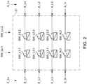
- Fig. 2 the structure of a separation point 12 for four lines Lx, preferably for a three-phase network with three phases L1, L2, L3 and a neutral conductor N is shown.
- All lines Lx of the isolating point 12 have inputs E_Lx, in the example shown the inputs E_Li of the phases Li and the input E_N of the neutral conductor N and outputs A_Lx, here in particular the outputs A_Li of the phases Li and the output A_N of the neutral conductor N.
- auxiliary voltages U_Lx are applied to the inputs E_Lx of the isolating point 12 and, in accordance with a switching pattern, the first switching contacts SW_Lx, 1 of the isolating point 12 are alternately closed and the second switching contacts SW_Lx, 2 are opened and then the second switching contacts SW_Lx, 2 closed and the first switch contacts SW_Lx, 1 opened.
- voltages between the output A_Lx of each line Lx of the disconnection point 12 and the intermediate circuit potential M of the photovoltaic inverter 1 are measured.
- the functionality of each switching contact SW_Lx, j is finally derived from these measured voltages for each switching pattern of the switching contacts SW_Lx, j.
- a separation point 12 between a photovoltaic inverter 1 and a supply network 7 or consumer 8 is shown in a three-phase network with three phases L1, L2 and L3 and a neutral conductor using the method according to the invention for checking the separation point 12.
- 13 auxiliary voltages U_Li are generated by corresponding devices, which are impressed in the test mode for testing the switching contacts SW_Li, j and SW_N, j between the inputs E_L1, E_L2, E_L3 of each phase L1, L2, L3 of the isolating point 12 and the intermediate circuit potential M.
- an auxiliary voltage U_L1 is applied via a coupling capacitor C is impressed between the input E_N of the neutral conductor N of the isolating point 12 and the intermediate circuit potential M.
- the voltages U_L1, GD; U_L2, GD; U_L3, GD between the output A_L1; A_L2; A_L3 each phase L1; L2; L3 of the separation point 12 and the output A_N of the neutral conductor N of the separation point 12 measured.
- the voltage U_MN between the output A_N of the neutral conductor N of the isolating point 12 and the intermediate circuit potential M is detected via a device 16.
- At least one device 14 for measuring the voltage U_L1, LT between the input E_L1 of phase L1 and the input E_N of the neutral conductor N of the separation point 12 is also provided at the input of the separation point 12.
- the evaluation device 17 the voltages at all switch contacts SW_Li, j and SW_N, j are calculated to derive the functionality of each switch contact SW_Li, j and SW_N, j from the measured voltages for each switch pattern of switch contacts SW_Li, j and SW_N, j. It is crucial that sufficient measurement information is available to be able to determine the voltages falling across the switch contacts in order to be able to draw conclusions about their functionality.
- the disconnection point 12 can be tested with a single switchover during the test mode. If the voltage difference at the switch contact is virtually zero, this is an indication that the switch contact is sticking, i.e. it is not working properly. If the voltage difference at a switching contact essentially corresponds to the impressed auxiliary voltage U_Li, U_N, the corresponding switching contact SW_Li, j or SW_N, j works.
- the following table shows the switching pattern for testing the switch contacts SW_Li, j; SW_N, j of the separation point 12 according to Fig. 3 .
- the total of eight switching contacts are activated in accordance with a switching pattern, which includes two switching states 1 and 2, and the corresponding voltages are measured for each switching state 1 or 2, so that the differential voltages on all switching contacts SW_Lx, j are calculated and thus the switching contacts SW_Lx stick , j can be determined.
- Switch contact Switching state 1 2nd SW_L1.1 closed open SW_L1.2 open closed SW_L2.1 closed open SW_L2.2 open closed SW_L3.1 closed open SW_L3.2 open closed SW_N, 1 closed open SW_N, 2nd open closed closed
Priority Applications (9)
| Application Number | Priority Date | Filing Date | Title |
|---|---|---|---|
| EP18198509.4A EP3633817A1 (fr) | 2018-10-03 | 2018-10-03 | Procédé de vérification d'un point de séparation d'un onduleur photovoltaïque et un tel onduleur photovoltaïque |
| ES19779492T ES2906373T3 (es) | 2018-10-03 | 2019-10-03 | Procedimiento para comprobar un punto de desconexión de un inversor fotovoltaico y un inversor fotovoltaico de este tipo |
| PCT/EP2019/076788 WO2020070234A1 (fr) | 2018-10-03 | 2019-10-03 | Procédé de vérification d'un point de coupure d'un onduleur photovoltaïque et onduleur photovoltaïque de ce type |
| EP19779492.8A EP3824524B1 (fr) | 2018-10-03 | 2019-10-03 | Procédé de vérification d'un point de séparation d'un onduleur photovoltaïque et un tel onduleur photovoltaïque |
| PL19779492T PL3824524T3 (pl) | 2018-10-03 | 2019-10-03 | Sposób badania punktu odłączania falownika fotowoltaicznego oraz taki falownik fotowoltaiczny |
| CN201980059047.6A CN112771749B (zh) | 2018-10-03 | 2019-10-03 | 用于测试光伏逆变器的分离点的方法以及这种类型的光伏逆变器 |
| AU2019352740A AU2019352740B2 (en) | 2018-10-03 | 2019-10-03 | Method for testing a disconnection point of a photovoltaic inverter, and a photovoltaic inverter of this type |
| BR112021003879-5A BR112021003879B1 (pt) | 2018-10-03 | 2019-10-03 | Método para a testagem de um ponto de desconexão de um inversor fotovoltaico com um circuito intermediário e inversor fotovoltaico para converter uma tensão cc em uma tensão ca |
| US17/274,245 US11125833B1 (en) | 2018-10-03 | 2019-10-03 | Method for testing a disconnection point of a photovoltaic inverter, and a photovoltaic inverter of this type |
Applications Claiming Priority (1)
| Application Number | Priority Date | Filing Date | Title |
|---|---|---|---|
| EP18198509.4A EP3633817A1 (fr) | 2018-10-03 | 2018-10-03 | Procédé de vérification d'un point de séparation d'un onduleur photovoltaïque et un tel onduleur photovoltaïque |
Publications (1)
| Publication Number | Publication Date |
|---|---|
| EP3633817A1 true EP3633817A1 (fr) | 2020-04-08 |
Family
ID=63762321
Family Applications (2)
| Application Number | Title | Priority Date | Filing Date |
|---|---|---|---|
| EP18198509.4A Withdrawn EP3633817A1 (fr) | 2018-10-03 | 2018-10-03 | Procédé de vérification d'un point de séparation d'un onduleur photovoltaïque et un tel onduleur photovoltaïque |
| EP19779492.8A Active EP3824524B1 (fr) | 2018-10-03 | 2019-10-03 | Procédé de vérification d'un point de séparation d'un onduleur photovoltaïque et un tel onduleur photovoltaïque |
Family Applications After (1)
| Application Number | Title | Priority Date | Filing Date |
|---|---|---|---|
| EP19779492.8A Active EP3824524B1 (fr) | 2018-10-03 | 2019-10-03 | Procédé de vérification d'un point de séparation d'un onduleur photovoltaïque et un tel onduleur photovoltaïque |
Country Status (7)
| Country | Link |
|---|---|
| US (1) | US11125833B1 (fr) |
| EP (2) | EP3633817A1 (fr) |
| CN (1) | CN112771749B (fr) |
| AU (1) | AU2019352740B2 (fr) |
| ES (1) | ES2906373T3 (fr) |
| PL (1) | PL3824524T3 (fr) |
| WO (1) | WO2020070234A1 (fr) |
Families Citing this family (1)
| Publication number | Priority date | Publication date | Assignee | Title |
|---|---|---|---|---|
| EP3619783B1 (fr) * | 2017-05-05 | 2021-07-07 | Signify Holding B.V. | Système et procédé de conversion d'énergie |
Citations (7)
| Publication number | Priority date | Publication date | Assignee | Title |
|---|---|---|---|---|
| JP2004187362A (ja) * | 2002-11-29 | 2004-07-02 | Matsushita Electric Works Ltd | 系統連系インバータ装置 |
| US20110298470A1 (en) * | 2010-06-04 | 2011-12-08 | Abb Oy | Detection of welded switch contacts in a line converter system |
| EP2608375A2 (fr) * | 2011-12-23 | 2013-06-26 | Kostal Industrie Elektrik GmbH | Agencement de commutation doté d'un onduleur et procédé de vérification du fonctionnement de commutateurs électromécaniques |
| US20140226365A1 (en) * | 2013-02-14 | 2014-08-14 | Fronius International Gmbh | Method for checking a separation point between a photovoltaic inverter and power supply network and photovoltaic inverter |
| EP2837012B1 (fr) | 2012-06-13 | 2015-11-04 | Fronius International GmbH | Procédé de vérification d'un point de coupure d'un onduleur photovoltaïque et onduleur photovoltaïque |
| US20160099569A1 (en) * | 2013-05-06 | 2016-04-07 | Refusol Gmbh | Energy generating device with functionally reliable potential separation |
| US20160268923A1 (en) * | 2013-11-25 | 2016-09-15 | Sma Solar Technology Ag | Method for operating an inverter and inverter comprising a switch between a center point of a dc link and a connection for a neutral conductor of an ac grid |
Family Cites Families (4)
| Publication number | Priority date | Publication date | Assignee | Title |
|---|---|---|---|---|
| CN102565691A (zh) | 2011-12-14 | 2012-07-11 | 广州三晶电气有限公司 | 一种并网逆变器的继电器失效检测装置及方法 |
| DE102013110240B4 (de) * | 2013-09-17 | 2017-09-07 | Sma Solar Technology Ag | Schaltungsanordnung für einen Photovoltaikwechselrichter zur Ausschaltentlastung mit Kurzschlussschaltern und Verwendungen der Schaltungsanordnung |
| CN203981841U (zh) | 2014-07-04 | 2014-12-03 | 广东易事特电源股份有限公司 | 单相光伏并网逆变器自动断路装置 |
| EP3252937A1 (fr) * | 2016-06-03 | 2017-12-06 | Fronius International GmbH | Onduleur et procédé de fonctionnement d'un onduleur |
-
2018
- 2018-10-03 EP EP18198509.4A patent/EP3633817A1/fr not_active Withdrawn
-
2019
- 2019-10-03 ES ES19779492T patent/ES2906373T3/es active Active
- 2019-10-03 CN CN201980059047.6A patent/CN112771749B/zh active Active
- 2019-10-03 AU AU2019352740A patent/AU2019352740B2/en active Active
- 2019-10-03 PL PL19779492T patent/PL3824524T3/pl unknown
- 2019-10-03 EP EP19779492.8A patent/EP3824524B1/fr active Active
- 2019-10-03 WO PCT/EP2019/076788 patent/WO2020070234A1/fr unknown
- 2019-10-03 US US17/274,245 patent/US11125833B1/en active Active
Patent Citations (8)
| Publication number | Priority date | Publication date | Assignee | Title |
|---|---|---|---|---|
| JP2004187362A (ja) * | 2002-11-29 | 2004-07-02 | Matsushita Electric Works Ltd | 系統連系インバータ装置 |
| US20110298470A1 (en) * | 2010-06-04 | 2011-12-08 | Abb Oy | Detection of welded switch contacts in a line converter system |
| EP2608375A2 (fr) * | 2011-12-23 | 2013-06-26 | Kostal Industrie Elektrik GmbH | Agencement de commutation doté d'un onduleur et procédé de vérification du fonctionnement de commutateurs électromécaniques |
| EP2837012B1 (fr) | 2012-06-13 | 2015-11-04 | Fronius International GmbH | Procédé de vérification d'un point de coupure d'un onduleur photovoltaïque et onduleur photovoltaïque |
| US20140226365A1 (en) * | 2013-02-14 | 2014-08-14 | Fronius International Gmbh | Method for checking a separation point between a photovoltaic inverter and power supply network and photovoltaic inverter |
| AT513866B1 (de) | 2013-02-14 | 2015-12-15 | Fronius Int Gmbh | Verfahren zur Prüfung einer Trennstelle eines Photovoltaik-Wechselrichters und Photovoltaik-Wechselrichter |
| US20160099569A1 (en) * | 2013-05-06 | 2016-04-07 | Refusol Gmbh | Energy generating device with functionally reliable potential separation |
| US20160268923A1 (en) * | 2013-11-25 | 2016-09-15 | Sma Solar Technology Ag | Method for operating an inverter and inverter comprising a switch between a center point of a dc link and a connection for a neutral conductor of an ac grid |
Also Published As
| Publication number | Publication date |
|---|---|
| ES2906373T3 (es) | 2022-04-18 |
| CN112771749A (zh) | 2021-05-07 |
| WO2020070234A1 (fr) | 2020-04-09 |
| EP3824524B1 (fr) | 2021-12-08 |
| PL3824524T3 (pl) | 2022-04-19 |
| CN112771749B (zh) | 2021-11-09 |
| AU2019352740B2 (en) | 2021-09-23 |
| BR112021003879A2 (pt) | 2021-05-18 |
| US11125833B1 (en) | 2021-09-21 |
| AU2019352740A1 (en) | 2021-04-01 |
| EP3824524A1 (fr) | 2021-05-26 |
| US20210311130A1 (en) | 2021-10-07 |
Similar Documents
| Publication | Publication Date | Title |
|---|---|---|
| DE102012104752B3 (de) | Verfahren zur Messung eines Isolationswiderstands für einen Wechselrichter und Wechselrichter | |
| DE102011054002B4 (de) | Dezentrale Energieerzeugungsanlage mit Einrichtung und Verfahren zur Inselnetzerkennung | |
| EP2994340B1 (fr) | Procédé pour faire fonctionner un dispositif de charge pour assurer la charge monophasée et polyphasée d'un accumulateur d'énergie d'un véhicule à moteur et dispositif de charge | |
| EP3059828B1 (fr) | Dispositif et procede de detection de courant differentiel | |
| EP2646841B1 (fr) | Surveillance de l'isolement dans un onduleur photovoltaïque | |
| EP3391519B1 (fr) | Onduleur et procede de fonctionnement d'un onduleur | |
| EP3625863B1 (fr) | Localisation d'un défaut de terre dans un réseau it | |
| DE102015114452B4 (de) | Verfahren zum Betrieb eines Wechselrichters und Wechselrichter | |
| EP2837012B1 (fr) | Procédé de vérification d'un point de coupure d'un onduleur photovoltaïque et onduleur photovoltaïque | |
| EP3254351B9 (fr) | Contrôle de filtre | |
| EP2994767A1 (fr) | Dispositif de production d'énergie à séparation de potentiel fiable | |
| DE102014202426B4 (de) | Verfahren zur Prüfung einer Trennstelle eines Photovoltaik-Wechselrichters und Photovoltaik-Wechselrichter | |
| EP3824524B1 (fr) | Procédé de vérification d'un point de séparation d'un onduleur photovoltaïque et un tel onduleur photovoltaïque | |
| EP2869072A1 (fr) | Dispositif et procédé de détection de l'énergie électrique de consommateurs mono ou multiphasés | |
| EP4252014B1 (fr) | Dispositif de surveillance destiné au fonctionnement de réseau de substitution | |
| EP2709226B1 (fr) | Agencement de circuit ainsi que convertisseur de niveau et circuit comparateur pour l'agencement de circuit | |
| DE102008009276A1 (de) | Elektrische Schaltung insbesondere für einen doppelt gespeisten Asynchrongenerator mit netzgekoppeltem Stator | |
| EP3629041A1 (fr) | Procédé et dispositif de mise en uvre d'un essai de coupure sur un onduleur | |
| EP2572921A1 (fr) | Surveillance d'un circuit |
Legal Events
| Date | Code | Title | Description |
|---|---|---|---|
| PUAI | Public reference made under article 153(3) epc to a published international application that has entered the european phase |
Free format text: ORIGINAL CODE: 0009012 |
|
| STAA | Information on the status of an ep patent application or granted ep patent |
Free format text: STATUS: THE APPLICATION HAS BEEN PUBLISHED |
|
| AK | Designated contracting states |
Kind code of ref document: A1 Designated state(s): AL AT BE BG CH CY CZ DE DK EE ES FI FR GB GR HR HU IE IS IT LI LT LU LV MC MK MT NL NO PL PT RO RS SE SI SK SM TR |
|
| AX | Request for extension of the european patent |
Extension state: BA ME |
|
| STAA | Information on the status of an ep patent application or granted ep patent |
Free format text: STATUS: THE APPLICATION IS DEEMED TO BE WITHDRAWN |
|
| 18D | Application deemed to be withdrawn |
Effective date: 20201009 |