EP3633809B1 - Cable ladder - Google Patents
Cable ladder Download PDFInfo
- Publication number
- EP3633809B1 EP3633809B1 EP19199488.8A EP19199488A EP3633809B1 EP 3633809 B1 EP3633809 B1 EP 3633809B1 EP 19199488 A EP19199488 A EP 19199488A EP 3633809 B1 EP3633809 B1 EP 3633809B1
- Authority
- EP
- European Patent Office
- Prior art keywords
- crosspiece
- joining piece
- crosspieces
- cable ladder
- dowel
- Prior art date
- Legal status (The legal status is an assumption and is not a legal conclusion. Google has not performed a legal analysis and makes no representation as to the accuracy of the status listed.)
- Active
Links
Images


Classifications
-
- H—ELECTRICITY
- H02—GENERATION; CONVERSION OR DISTRIBUTION OF ELECTRIC POWER
- H02G—INSTALLATION OF ELECTRIC CABLES OR LINES, OR OF COMBINED OPTICAL AND ELECTRIC CABLES OR LINES
- H02G3/00—Installations of electric cables or lines or protective tubing therefor in or on buildings, equivalent structures or vehicles
- H02G3/02—Details
- H02G3/04—Protective tubing or conduits, e.g. cable ladders or cable troughs
- H02G3/0456—Ladders or other supports
-
- B—PERFORMING OPERATIONS; TRANSPORTING
- B21—MECHANICAL METAL-WORKING WITHOUT ESSENTIALLY REMOVING MATERIAL; PUNCHING METAL
- B21D—WORKING OR PROCESSING OF SHEET METAL OR METAL TUBES, RODS OR PROFILES WITHOUT ESSENTIALLY REMOVING MATERIAL; PUNCHING METAL
- B21D39/00—Application of procedures in order to connect objects or parts, e.g. coating with sheet metal otherwise than by plating; Tube expanders
- B21D39/04—Application of procedures in order to connect objects or parts, e.g. coating with sheet metal otherwise than by plating; Tube expanders of tubes with tubes; of tubes with rods
- B21D39/044—Application of procedures in order to connect objects or parts, e.g. coating with sheet metal otherwise than by plating; Tube expanders of tubes with tubes; of tubes with rods perpendicular
-
- B—PERFORMING OPERATIONS; TRANSPORTING
- B21—MECHANICAL METAL-WORKING WITHOUT ESSENTIALLY REMOVING MATERIAL; PUNCHING METAL
- B21D—WORKING OR PROCESSING OF SHEET METAL OR METAL TUBES, RODS OR PROFILES WITHOUT ESSENTIALLY REMOVING MATERIAL; PUNCHING METAL
- B21D53/00—Making other particular articles
- B21D53/36—Making other particular articles clips, clamps, or like fastening or attaching devices, e.g. for electric installation
-
- B—PERFORMING OPERATIONS; TRANSPORTING
- B21—MECHANICAL METAL-WORKING WITHOUT ESSENTIALLY REMOVING MATERIAL; PUNCHING METAL
- B21D—WORKING OR PROCESSING OF SHEET METAL OR METAL TUBES, RODS OR PROFILES WITHOUT ESSENTIALLY REMOVING MATERIAL; PUNCHING METAL
- B21D39/00—Application of procedures in order to connect objects or parts, e.g. coating with sheet metal otherwise than by plating; Tube expanders
- B21D39/06—Application of procedures in order to connect objects or parts, e.g. coating with sheet metal otherwise than by plating; Tube expanders of tubes in openings, e.g. rolling-in
- B21D39/063—Application of procedures in order to connect objects or parts, e.g. coating with sheet metal otherwise than by plating; Tube expanders of tubes in openings, e.g. rolling-in for assembling ladders
-
- F—MECHANICAL ENGINEERING; LIGHTING; HEATING; WEAPONS; BLASTING
- F16—ENGINEERING ELEMENTS AND UNITS; GENERAL MEASURES FOR PRODUCING AND MAINTAINING EFFECTIVE FUNCTIONING OF MACHINES OR INSTALLATIONS; THERMAL INSULATION IN GENERAL
- F16B—DEVICES FOR FASTENING OR SECURING CONSTRUCTIONAL ELEMENTS OR MACHINE PARTS TOGETHER, e.g. NAILS, BOLTS, CIRCLIPS, CLAMPS, CLIPS OR WEDGES; JOINTS OR JOINTING
- F16B7/00—Connections of rods or tubes, e.g. of non-circular section, mutually, including resilient connections
- F16B7/04—Clamping or clipping connections
- F16B7/044—Clamping or clipping connections for rods or tubes being in angled relationship
- F16B7/0446—Clamping or clipping connections for rods or tubes being in angled relationship for tubes using the innerside thereof
Definitions
- the invention is comprised in the field of the cable ladder type cable trays which are used for guiding electric cables, fiber optic cables or cables of another type.
- the invention specifically relates to cable ladders in which both the side rails and the crosspieces are profiles made of a polymeric material.
- the invention relates to a cable ladder of the type comprising two coplanar side rails joined to one another by a plurality of crosspieces spaced from one another, said plurality of crosspieces constituting a discontinuous support surface for cables, in which each of said crosspieces is a profile made of a polymeric material and each of said side rails is a profile made of a polymeric material, and wherein the ends of said crosspieces fit in an inner side of the side rails facing an inner side of the opposite side rail.
- the purpose of the invention is to provide a cable tray of the type indicated above, which can have more varied shapes and can be readily built.
- this configuration provides a modular system which allows readily constructing different cable ladder segments with various shapes. For example, as will be seen below in the description of embodiments, by using a single crosspiece model and different joining pieces it is possible to join the crosspieces to an orthogonal straight side rail, to a straight side rail forming an angle between the crosspiece and the side rail, and to a curved side rail.
- the first side of the joining piece can be formed for snap fitting with the outer surface of the crosspiece.
- the first side of the joining piece comprises a dowel having a shape complementary to the inner perimeter of the crosspieces, such that said dowel is tightly introduced inside a crosspiece, at the end of said crosspiece and in the longitudinal direction thereof.
- the crosspieces comprise through holes distributed along the crosspiece. These through holes allow arranging zip ties for holding the cables laid in the cable tray.
- the dowel comprises a tooth which is snapped into one of the through holes of the crosspiece. The joining piece is thereby fixed robustly to the end of the crosspiece, taking advantage of the presence of one of the through holes in said crosspiece.
- the dowel is formed by two facing arms extending in the longitudinal direction of said dowel and a central tab in which the tooth is arranged and extending in cantilever fashion between the two arms.
- This configuration of the dowel is robust and allows good elastic bending of the central tab to obtain easy snap fitting of the tooth in the through hole.
- the crosspieces have a C-shaped cross-section with a web and two facing flanges, said flanges demarcating between them an open side of the crosspiece opposite said web.
- the two flanges are bent towards the inside of the crosspiece forming respective inner side tracks.
- the open side and the two inner side tracks form a guide along the crosspiece which is used for fixing cable holding devices, such as clamps for example provided with tightening means for holding cable bundles.
- each of the arms of the first side of the joining piece comprises a rib protruding laterally from the arm, said ribs being formed such that they are tightly introduced in the inner side tracks.
- the joining piece is thereby fixed to the crosspiece in a particularly robust manner and the operation of introducing the dowel in the crosspiece is even further facilitated.
- the second side of the joining piece is formed for snap fitting in the inner side of a side rail in an orthogonal direction with respect to the longitudinal direction of said side rail, such that through said joining piece is joined by snap fitting the end of a crosspiece to the inner side of a side rail.
- Another advantage of this system according to the invention is that it allows sending a half-assembled cable ladder to the site where it is to be installed, with the joining pieces fitted in the inner sides of the side rails but with the crosspieces not being assembled, subsequently saving in transport volumes.
- the end user can assemble the cable ladder on site in an easy manner and without requiring any particular machinery or skill. To that end, the end user must simply fit the ends of the crosspieces in the joining pieces which have been previously fitted in the side rails before transport.
- the inner side of the side rails comprises a channel and a plurality of openings spaced apart from one another along the longitudinal direction of said side rails.
- the second side of the joining piece comprises a block having on its outer surface at least one transverse groove, said block being formed such that it is introduced under pressure in said channel through one of said openings, and said channel comprises a projection which is introduced in said transverse groove of the block.
- the block comprises two of said transverse grooves, arranged in one and the same plane on opposite sides of said block.
- This configuration allows interchangeably arranging the crosspiece in two positions that are turned over with respect to one another, such that the projection of the channel is introduced in either of said transverse grooves.
- the first side of the joining piece is formed for snap fitting in the ends of two crosspieces arranged coplanar and forming an angle with respect to one another. This allows forming a framework of crosspieces in which some crosspieces are not orthogonal to the side rails, which facilitates the construction of cable ladder segments with more complex shapes, particularly bypass segments.
- the first side of the joining piece comprises two dowels forming an angle with respect to one another, each of said dowels having a shape complementary to the inner perimeter of a crosspiece, such that each of said dowels is tightly introduced inside a crosspiece, at the end of said crosspiece and in the longitudinal direction thereof.
- This solution makes the cable ladder more robust and furthermore prevents the joining piece from interfering in the space surrounding the crosspieces, where the cables are laid.
- each of said first side and second side of the joining piece is formed for snap fitting in the end of a crosspiece, such that through said joining piece the ends of two of said crosspieces aligned with one another are joined by fitting.
- each of said first side and second side of the joining piece comprises a dowel having a shape complementary to the inner perimeter of the crosspieces, such that said dowel is tightly introduced inside a crosspiece, at the end of said crosspiece and in the longitudinal direction thereof, and said joining piece comprises a partition arranged between the two dowels of the first side and of the second side, said partition protruding from the perimeter of said two dowels.
- This solution makes the cable ladder more robust and furthermore prevents the joining piece from interfering in the space where the cables are laid.
- the partition acts as a stop for assuring correct positioning of the dowels in the crosspieces.
- the first side and second side of the joining piece are equal to one another.
- the second side of the joining piece is formed for snap fitting in a crosspiece in an orthogonal direction with respect to the longitudinal direction of said crosspiece, such that through said joining piece the end of a first crosspiece is joined to a central segment of a second crosspiece arranged orthogonally to said first crosspiece by fitting.
- the second side of the joining piece comprises a grip encircling the outer surface of the second crosspiece.
- the grip is formed by a bent plate which is adjoined to said outer surface of the second crosspiece, whereby the second side of the joining piece virtually does not interfere in the space around the crosspieces and does not form projections on which the cables may accidentally be snagged.
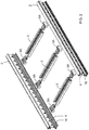
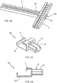
- Figures 1 to 15 show a first embodiment in which the cable ladder is straight, with the side rails parallel to one another and the crosspieces arranged orthogonally to said side rails and joined thereto at their ends.
- the cable ladder 1 comprises two coplanar side rails 2 joined to one another by a plurality of crosspieces 3 spaced from one another.
- the set of these crosspieces 3 constitutes a discontinuous support surface for cables.
- the ends of said crosspieces 3 fit in an inner side 4 of the side rails 2 facing an inner side 4 of the opposite side rail 2.
- the cable ladder 1 has the particularity that the ends of the crosspieces 3 are joined by fitting in the inner side 4 of the side rails through an interposed joining piece.
- this joining piece is a first joining piece 5A formed specifically for attaching an end of a crosspiece 3 to the inner side 4 of a side rail 2 arranged perpendicular to said crosspiece 3.
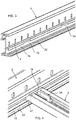
- Figure 3 shows in greater detail the shape of the side rails 2.
- the inner side 4 of the side rail 2 comprises a channel 18 and a plurality of openings 19 spaced apart from one another along the longitudinal direction of the side rail 2.
- This shape of the side rails 2 is known in the state of the art.
- the invention has the particularity that it allows the ends of the crosspieces 3 to snap fit in the inner side 4 of the side rails 2 through a joining piece that is snap fit in both parts, instead of doing it directly like in the prior art.
- FIGS 5 to 9 show in greater detail the shape of the crosspieces 3.
- Each crosspiece 3 has a C-shaped cross-section with a web 8 and two facing flanges 9.
- the flanges 9 demarcate between them an open side 10 of the crosspiece 3, opposite said web 8, and are bent towards the inside of the crosspiece 3 forming respective inner side tracks 16.
- This shape of the crosspieces 3 is known in the state of the art.
- the invention has the particularity that it allows the ends of the crosspieces 3 to snap fit in another element of the cable ladder through a joining piece snap fit in both parts, whereby it is no longer necessary for the ends of the crosspieces 3 to be machined with a specific shape for fitting in said element.
- the crosspiece 3 shown in Figures 5 to 9 is a profile obtained by extrusion in which have been machined the through holes 11, but no specific shape has been machined at the ends thereof.
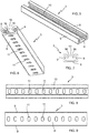
- Figures 10 to 12 show in greater detail the first joining piece 5A, comprising a first side 6 formed for snap fitting in the end of the crosspiece 3 and a second side 7 formed for snap fitting in the inner side 4 of the side rail 2.
- the first side 6 of the first joining piece 5A comprises a dowel 12 having a shape complementary to the inner perimeter of the crosspieces 3.
- the dowel 12 is formed by two facing arms 14 extending in the longitudinal direction of said dowel 12 and a central tab 15 extending in cantilever fashion between said arms 14.
- a tooth 13 is formed at one end of the central tab 15.
- Each of these two arms 14 comprises a rib 17 protruding laterally from said arm 14.
- the second side 7 comprises a cuboid shaped block 20 having on its outer surface two transverse grooves 21, arranged in one and the same plane on opposite sides of said block 20.
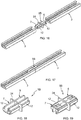
- Figure 16 and 17 show a second embodiment, in which two aligned crosspieces 3 are joined to one another at their ends and by fitting through a second joining piece 5B.
- the two crosspieces 3 are identical to those described above for the first embodiment, except eventually their length.
- Both the first side 6 and the second side 7 of this second joining piece 5B are formed for snap fitting in the end of a crosspiece 3.
- the first side 6 and the second side 7 of the joining piece 5B are equal to one another, and they are equal to the first side 6 of the first joining piece 5A described above.
- a partition 24 protruding from the perimeter of said two dowels 12.
- the manner in which each of the two dowels 12 is introduced in the end of a crosspiece 3 is the same as the manner described above for the first embodiment.
- the partition 24 acts as a stop for the introduction of each dowel 12 at the end of a crosspiece 3.
- a cable ladder 1 (not depicted) like that shown in Figure 1 can be constructed, but in which the crosspieces attaching the two side rails 2 are composite crosspieces like in Figure 17 , formed by two crosspieces 3 aligned and joined at their ends and by snap fitting through a second joining piece 5B.
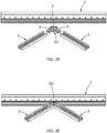
- Figures 20 to 22 show a third embodiment, in which two crosspieces 3 arranged orthogonally are joined to one another and by snap fitting through a third joining piece 5C.
- the two crosspieces 3 are identical to those described above for the first embodiment, except eventually in length.
- the second side of this third joining piece 5C is formed for snap fitting in a central segment of a crosspiece 3 in an orthogonal direction with respect to the longitudinal direction of said crosspiece 3.
- the second side 7 of the third joining piece 5C comprises a grip 23 formed by a bent plate having a complementary shape of the outer surface of the crosspiece 3, such that when the second side 7 is snap fit in said crosspiece 3 as shown in Figures 21 and 22 , said bent plate is adjoined to the outer surface of the crosspiece 3.
- the first side 6 of this third joining piece 5C is equal to the first side 6 of the first joining piece 5A described above.
- the manner in which the dowel 12 of the first side 6 is introduced in the end of a crosspiece 3 is the same as that described above for the first embodiment. It can be observed that the shape of the second side 7 of the third joining piece 5C is such that it fits in any position along the crosspiece 3.
- the second side 7 of the joining piece is formed such that it cooperates with a singular element formed in the crosspiece 3, such that it can fit only in certain positions along the crosspiece 3.
- the second side 7 can have a shape like that of the third joining piece 5C but with a tooth intended for cooperating with one of the through holes 11 of the crosspiece 3.
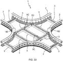
- a cable ladder 1 for example like that shown in Figure 33 can be constructed, forming an X-crossing. It is also possible to build crossings with different, non-orthogonal angles, modifying to that end the angles of the different joining pieces.
- Figures 25 and 26 show a fourth embodiment, in which two coplanar crosspieces 3 forming an angle are joined to a straight side rail 2 at one and the same point and by snap fitting through a fourth joining piece 5D.
- the angle formed by the two crosspieces 3 is 90°
- the angle formed by each crosspiece 3 with the side rail 2 is 45°.
- the side rail 2 and the two crosspieces 3 are identical to those described above for the first embodiment, except eventually in length.
- the fourth joining piece 5D has a first side 6 comprising two dowels 12 forming an angle with respect to one another. In the depicted example the angle formed by the two dowels 12 is 90°.
- the second side 7 of the fourth joining piece 5D has a shape similar to that of the second side 7 of the first joining piece 5A described above: it comprises a block 20 having on its outer surface two transverse grooves 21 arranged in one and the same plane on opposite sides of said block 20.
- the block 20 is a cuboid which is turned 45° with respect to the longitudinal direction of the side rail 2 and the vertex opposite the dowels 12 is truncated.
- the manner in which the block 20 is introduced in an opening 19 of the channel 18 of the inner side of the side rail 2 for snap fitting therein, such that the projection 22 is introduced in the transverse groove 21, is the same as that described above for the first embodiment.
- a cable ladder 1 (not depicted) can be constructed like that shown in Figure 1 , but in which the crosspieces 3 attaching the two side rails 2 are arranged forming an 90° angle between one another and a 45° angle with the side rails 2, and such that two crosspieces 3 are joined at one and the same point of a side rail 2 by snap fitting through the fourth joining piece 5D.
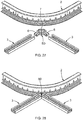
- Figures 27 and 28 show a variant of the fourth embodiment which differs from same only in that the side rail 2 is curved.
- the same fourth joining pieces 5D are used in the same manner as in the fourth embodiment described above.
- a cable ladder 1 like that shown in Figure 32 forming a T-joint
- a cable ladder 1 like that shown in Figure 33 forming an X-crossing
- both the first side 6 and the second side 7 of the joining piece are each formed for snap fitting in the ends of two crosspieces 3 arranged coplanar and forming an angle with respect to one another.
- both the first side 6 and the second side 7 of the joining piece can be like the first side 6 of the fourth joining piece 5D depicted in Figures 29 to 31 .
- a cable ladder 1 can be constructed in which the four crosspieces 3 are joined at their ends to one and the same joining piece.
- the second side 7 of the joining piece is formed for snap fitting in the end of a single crosspiece.
- the second side 7 of the joining piece can be like the first side 6 or the second side 7 of the second joining piece 5B depicted in Figures 18 and 19 .
- both the side rails 2 and the crosspieces 3 as well as the joining pieces 5A, 5B, 5C, 5D are made of a polymeric material, preferably an electrically insulating material, such as for example PVC (polyvinyl chloride) with a surface resistivity greater than 100 M ⁇ (surface resistivity measured according to standard EN 62631-3-2:2016).
- the polymeric material constituting side rails 2, crosspieces 3, and joining pieces 5A, 5B, 5C, 5D can be different. However, preferably all these components of the cable ladder are made from the same polymeric material.
- the side rails 2 and the crosspieces 3 are profiles, preferably extruded profiles.
- the joining pieces 5A, 5B, 5C, 5D are molded parts.
Landscapes
- Engineering & Computer Science (AREA)
- Mechanical Engineering (AREA)
- Architecture (AREA)
- Civil Engineering (AREA)
- Structural Engineering (AREA)
- Ladders (AREA)
- Details Of Indoor Wiring (AREA)
- Installation Of Indoor Wiring (AREA)
Priority Applications (1)
| Application Number | Priority Date | Filing Date | Title |
|---|---|---|---|
| PL19199488T PL3633809T3 (pl) | 2018-10-02 | 2019-09-25 | Drabinka kablowa |
Applications Claiming Priority (1)
| Application Number | Priority Date | Filing Date | Title |
|---|---|---|---|
| ES201831499U ES1220465Y (es) | 2018-10-02 | 2018-10-02 | Escalera portacables |
Publications (2)
| Publication Number | Publication Date |
|---|---|
| EP3633809A1 EP3633809A1 (en) | 2020-04-08 |
| EP3633809B1 true EP3633809B1 (en) | 2021-12-15 |
Family
ID=64271263
Family Applications (1)
| Application Number | Title | Priority Date | Filing Date |
|---|---|---|---|
| EP19199488.8A Active EP3633809B1 (en) | 2018-10-02 | 2019-09-25 | Cable ladder |
Country Status (4)
| Country | Link |
|---|---|
| EP (1) | EP3633809B1 (pl) |
| ES (2) | ES1220465Y (pl) |
| PL (1) | PL3633809T3 (pl) |
| PT (1) | PT3633809T (pl) |
Cited By (1)
| Publication number | Priority date | Publication date | Assignee | Title |
|---|---|---|---|---|
| WO2023126072A1 (en) * | 2021-12-30 | 2023-07-06 | Eaton Intelligent Power Limited | Snap plug for cable tray |
Families Citing this family (3)
| Publication number | Priority date | Publication date | Assignee | Title |
|---|---|---|---|---|
| ES1246836Y (es) * | 2020-03-18 | 2020-08-28 | Unex Aparellaje Electrico Sl | Barra de soporte para bandejas portacables |
| ES1246865Y (es) * | 2020-03-18 | 2020-08-28 | Unex Aparellaje Electrico Sl | "Barra de soporte para bandejas portacables" |
| US11979009B2 (en) * | 2022-02-25 | 2024-05-07 | Abb Schweiz Ag | Cable tray support apparatus and system |
Family Cites Families (5)
| Publication number | Priority date | Publication date | Assignee | Title |
|---|---|---|---|---|
| US4080742A (en) * | 1974-11-04 | 1978-03-28 | Osterried James L | Kit of parts for forming a curved member, and curved member formed thereby |
| IL124018A (en) * | 1998-04-08 | 2001-01-11 | Molek Efraim | Interlocking modular ladder-type cable tray |
| ES1126630Y (es) | 2014-09-25 | 2015-09-03 | Unex Aparellaje Electrico Sl | Escalera portacables |
| ES1164633Y (es) | 2016-07-20 | 2016-12-09 | Unex Aparellaje Electrico Sl | Dispositivo para sujetar un cable o un haz de cables en una bandeja portacables |
| ES1200090Y (es) | 2017-10-25 | 2018-02-23 | Unex Aparellaje Electrico Sl | Esquina de escalera portacables |
-
2018
- 2018-10-02 ES ES201831499U patent/ES1220465Y/es not_active Expired - Fee Related
-
2019
- 2019-09-25 EP EP19199488.8A patent/EP3633809B1/en active Active
- 2019-09-25 PL PL19199488T patent/PL3633809T3/pl unknown
- 2019-09-25 ES ES19199488T patent/ES2908301T3/es active Active
- 2019-09-25 PT PT191994888T patent/PT3633809T/pt unknown
Cited By (1)
| Publication number | Priority date | Publication date | Assignee | Title |
|---|---|---|---|---|
| WO2023126072A1 (en) * | 2021-12-30 | 2023-07-06 | Eaton Intelligent Power Limited | Snap plug for cable tray |
Also Published As
| Publication number | Publication date |
|---|---|
| ES1220465Y (es) | 2019-02-08 |
| ES1220465U (es) | 2018-11-15 |
| EP3633809A1 (en) | 2020-04-08 |
| PT3633809T (pt) | 2022-03-18 |
| ES2908301T3 (es) | 2022-04-28 |
| PL3633809T3 (pl) | 2022-04-04 |
Similar Documents
| Publication | Publication Date | Title |
|---|---|---|
| EP3633809B1 (en) | Cable ladder | |
| US5465929A (en) | Ladder-type cable tray system | |
| US7703248B2 (en) | Hollow interconnecting panels as lost formwork | |
| US3304108A (en) | Tube construction | |
| US6118075A (en) | Stackable universal pitch cable trough system | |
| US4907767A (en) | Stackable modular duct assemblies | |
| US11008753B2 (en) | Corrugated bridging member | |
| US9866000B2 (en) | Cable ladder | |
| SU1582994A3 (ru) | Носитель линий передачи энергии дл размещени между неподвижным источником и подвижным потребителем | |
| TWM481420U (zh) | Lc光纖可疊加組合式適配器 | |
| US4319724A (en) | Lightweight cable ladder | |
| GB1581375A (en) | Panel connectors | |
| JP2010164190A (ja) | 管台および曲がり管並設保持構造 | |
| KR102042237B1 (ko) | 케이블 트레이 | |
| TWI634273B (zh) | Cable chain | |
| EP0169697B1 (en) | Jointing system | |
| EP3477805B1 (en) | Cable ladder corner | |
| KR101850067B1 (ko) | 조립식 트레이용 측판 | |
| US20080199142A1 (en) | Coupler for Cable Trough | |
| KR200485887Y1 (ko) | 조립식 트레이용 가로대 | |
| EP3633808B1 (en) | Cable ladder | |
| US20190186168A1 (en) | Fence panel system | |
| US20120285740A1 (en) | Cable assembly | |
| CN111527657A (zh) | 缆线盘组件 | |
| EP3522315A1 (en) | Connection device for connecting two cable tray segments at a variable angle |
Legal Events
| Date | Code | Title | Description |
|---|---|---|---|
| PUAI | Public reference made under article 153(3) epc to a published international application that has entered the european phase |
Free format text: ORIGINAL CODE: 0009012 |
|
| STAA | Information on the status of an ep patent application or granted ep patent |
Free format text: STATUS: THE APPLICATION HAS BEEN PUBLISHED |
|
| AK | Designated contracting states |
Kind code of ref document: A1 Designated state(s): AL AT BE BG CH CY CZ DE DK EE ES FI FR GB GR HR HU IE IS IT LI LT LU LV MC MK MT NL NO PL PT RO RS SE SI SK SM TR |
|
| AX | Request for extension of the european patent |
Extension state: BA ME |
|
| STAA | Information on the status of an ep patent application or granted ep patent |
Free format text: STATUS: REQUEST FOR EXAMINATION WAS MADE |
|
| 17P | Request for examination filed |
Effective date: 20201002 |
|
| RBV | Designated contracting states (corrected) |
Designated state(s): AL AT BE BG CH CY CZ DE DK EE ES FI FR GB GR HR HU IE IS IT LI LT LU LV MC MK MT NL NO PL PT RO RS SE SI SK SM TR |
|
| GRAP | Despatch of communication of intention to grant a patent |
Free format text: ORIGINAL CODE: EPIDOSNIGR1 |
|
| STAA | Information on the status of an ep patent application or granted ep patent |
Free format text: STATUS: GRANT OF PATENT IS INTENDED |
|
| INTG | Intention to grant announced |
Effective date: 20210712 |
|
| GRAS | Grant fee paid |
Free format text: ORIGINAL CODE: EPIDOSNIGR3 |
|
| GRAA | (expected) grant |
Free format text: ORIGINAL CODE: 0009210 |
|
| STAA | Information on the status of an ep patent application or granted ep patent |
Free format text: STATUS: THE PATENT HAS BEEN GRANTED |
|
| AK | Designated contracting states |
Kind code of ref document: B1 Designated state(s): AL AT BE BG CH CY CZ DE DK EE ES FI FR GB GR HR HU IE IS IT LI LT LU LV MC MK MT NL NO PL PT RO RS SE SI SK SM TR |
|
| REG | Reference to a national code |
Ref country code: GB Ref legal event code: FG4D Ref country code: CH Ref legal event code: EP |
|
| REG | Reference to a national code |
Ref country code: IE Ref legal event code: FG4D Ref country code: DE Ref legal event code: R096 Ref document number: 602019010057 Country of ref document: DE |
|
| REG | Reference to a national code |
Ref country code: AT Ref legal event code: REF Ref document number: 1456193 Country of ref document: AT Kind code of ref document: T Effective date: 20220115 |
|
| REG | Reference to a national code |
Ref country code: PT Ref legal event code: SC4A Ref document number: 3633809 Country of ref document: PT Date of ref document: 20220318 Kind code of ref document: T Free format text: AVAILABILITY OF NATIONAL TRANSLATION Effective date: 20220314 |
|
| REG | Reference to a national code |
Ref country code: LT Ref legal event code: MG9D |
|
| REG | Reference to a national code |
Ref country code: NL Ref legal event code: MP Effective date: 20211215 |
|
| REG | Reference to a national code |
Ref country code: ES Ref legal event code: FG2A Ref document number: 2908301 Country of ref document: ES Kind code of ref document: T3 Effective date: 20220428 |
|
| PG25 | Lapsed in a contracting state [announced via postgrant information from national office to epo] |
Ref country code: RS Free format text: LAPSE BECAUSE OF FAILURE TO SUBMIT A TRANSLATION OF THE DESCRIPTION OR TO PAY THE FEE WITHIN THE PRESCRIBED TIME-LIMIT Effective date: 20211215 Ref country code: LT Free format text: LAPSE BECAUSE OF FAILURE TO SUBMIT A TRANSLATION OF THE DESCRIPTION OR TO PAY THE FEE WITHIN THE PRESCRIBED TIME-LIMIT Effective date: 20211215 Ref country code: FI Free format text: LAPSE BECAUSE OF FAILURE TO SUBMIT A TRANSLATION OF THE DESCRIPTION OR TO PAY THE FEE WITHIN THE PRESCRIBED TIME-LIMIT Effective date: 20211215 Ref country code: BG Free format text: LAPSE BECAUSE OF FAILURE TO SUBMIT A TRANSLATION OF THE DESCRIPTION OR TO PAY THE FEE WITHIN THE PRESCRIBED TIME-LIMIT Effective date: 20220315 |
|
| REG | Reference to a national code |
Ref country code: AT Ref legal event code: MK05 Ref document number: 1456193 Country of ref document: AT Kind code of ref document: T Effective date: 20211215 |
|
| PG25 | Lapsed in a contracting state [announced via postgrant information from national office to epo] |
Ref country code: SE Free format text: LAPSE BECAUSE OF FAILURE TO SUBMIT A TRANSLATION OF THE DESCRIPTION OR TO PAY THE FEE WITHIN THE PRESCRIBED TIME-LIMIT Effective date: 20211215 Ref country code: NO Free format text: LAPSE BECAUSE OF FAILURE TO SUBMIT A TRANSLATION OF THE DESCRIPTION OR TO PAY THE FEE WITHIN THE PRESCRIBED TIME-LIMIT Effective date: 20220315 Ref country code: LV Free format text: LAPSE BECAUSE OF FAILURE TO SUBMIT A TRANSLATION OF THE DESCRIPTION OR TO PAY THE FEE WITHIN THE PRESCRIBED TIME-LIMIT Effective date: 20211215 Ref country code: HR Free format text: LAPSE BECAUSE OF FAILURE TO SUBMIT A TRANSLATION OF THE DESCRIPTION OR TO PAY THE FEE WITHIN THE PRESCRIBED TIME-LIMIT Effective date: 20211215 Ref country code: GR Free format text: LAPSE BECAUSE OF FAILURE TO SUBMIT A TRANSLATION OF THE DESCRIPTION OR TO PAY THE FEE WITHIN THE PRESCRIBED TIME-LIMIT Effective date: 20220316 |
|
| PG25 | Lapsed in a contracting state [announced via postgrant information from national office to epo] |
Ref country code: NL Free format text: LAPSE BECAUSE OF FAILURE TO SUBMIT A TRANSLATION OF THE DESCRIPTION OR TO PAY THE FEE WITHIN THE PRESCRIBED TIME-LIMIT Effective date: 20211215 |
|
| PG25 | Lapsed in a contracting state [announced via postgrant information from national office to epo] |
Ref country code: SM Free format text: LAPSE BECAUSE OF FAILURE TO SUBMIT A TRANSLATION OF THE DESCRIPTION OR TO PAY THE FEE WITHIN THE PRESCRIBED TIME-LIMIT Effective date: 20211215 Ref country code: SK Free format text: LAPSE BECAUSE OF FAILURE TO SUBMIT A TRANSLATION OF THE DESCRIPTION OR TO PAY THE FEE WITHIN THE PRESCRIBED TIME-LIMIT Effective date: 20211215 Ref country code: RO Free format text: LAPSE BECAUSE OF FAILURE TO SUBMIT A TRANSLATION OF THE DESCRIPTION OR TO PAY THE FEE WITHIN THE PRESCRIBED TIME-LIMIT Effective date: 20211215 Ref country code: EE Free format text: LAPSE BECAUSE OF FAILURE TO SUBMIT A TRANSLATION OF THE DESCRIPTION OR TO PAY THE FEE WITHIN THE PRESCRIBED TIME-LIMIT Effective date: 20211215 Ref country code: CZ Free format text: LAPSE BECAUSE OF FAILURE TO SUBMIT A TRANSLATION OF THE DESCRIPTION OR TO PAY THE FEE WITHIN THE PRESCRIBED TIME-LIMIT Effective date: 20211215 |
|
| PG25 | Lapsed in a contracting state [announced via postgrant information from national office to epo] |
Ref country code: AT Free format text: LAPSE BECAUSE OF FAILURE TO SUBMIT A TRANSLATION OF THE DESCRIPTION OR TO PAY THE FEE WITHIN THE PRESCRIBED TIME-LIMIT Effective date: 20211215 |
|
| REG | Reference to a national code |
Ref country code: DE Ref legal event code: R097 Ref document number: 602019010057 Country of ref document: DE |
|
| PG25 | Lapsed in a contracting state [announced via postgrant information from national office to epo] |
Ref country code: IS Free format text: LAPSE BECAUSE OF FAILURE TO SUBMIT A TRANSLATION OF THE DESCRIPTION OR TO PAY THE FEE WITHIN THE PRESCRIBED TIME-LIMIT Effective date: 20220415 |
|
| PLBE | No opposition filed within time limit |
Free format text: ORIGINAL CODE: 0009261 |
|
| STAA | Information on the status of an ep patent application or granted ep patent |
Free format text: STATUS: NO OPPOSITION FILED WITHIN TIME LIMIT |
|
| PG25 | Lapsed in a contracting state [announced via postgrant information from national office to epo] |
Ref country code: DK Free format text: LAPSE BECAUSE OF FAILURE TO SUBMIT A TRANSLATION OF THE DESCRIPTION OR TO PAY THE FEE WITHIN THE PRESCRIBED TIME-LIMIT Effective date: 20211215 Ref country code: AL Free format text: LAPSE BECAUSE OF FAILURE TO SUBMIT A TRANSLATION OF THE DESCRIPTION OR TO PAY THE FEE WITHIN THE PRESCRIBED TIME-LIMIT Effective date: 20211215 |
|
| 26N | No opposition filed |
Effective date: 20220916 |
|
| PG25 | Lapsed in a contracting state [announced via postgrant information from national office to epo] |
Ref country code: SI Free format text: LAPSE BECAUSE OF FAILURE TO SUBMIT A TRANSLATION OF THE DESCRIPTION OR TO PAY THE FEE WITHIN THE PRESCRIBED TIME-LIMIT Effective date: 20211215 |
|
| PG25 | Lapsed in a contracting state [announced via postgrant information from national office to epo] |
Ref country code: MC Free format text: LAPSE BECAUSE OF FAILURE TO SUBMIT A TRANSLATION OF THE DESCRIPTION OR TO PAY THE FEE WITHIN THE PRESCRIBED TIME-LIMIT Effective date: 20211215 |
|
| REG | Reference to a national code |
Ref country code: CH Ref legal event code: PL |
|
| REG | Reference to a national code |
Ref country code: BE Ref legal event code: MM Effective date: 20220930 |
|
| PG25 | Lapsed in a contracting state [announced via postgrant information from national office to epo] |
Ref country code: LU Free format text: LAPSE BECAUSE OF NON-PAYMENT OF DUE FEES Effective date: 20220925 |
|
| PG25 | Lapsed in a contracting state [announced via postgrant information from national office to epo] |
Ref country code: LI Free format text: LAPSE BECAUSE OF NON-PAYMENT OF DUE FEES Effective date: 20220930 Ref country code: IE Free format text: LAPSE BECAUSE OF NON-PAYMENT OF DUE FEES Effective date: 20220925 Ref country code: CH Free format text: LAPSE BECAUSE OF NON-PAYMENT OF DUE FEES Effective date: 20220930 |
|
| PG25 | Lapsed in a contracting state [announced via postgrant information from national office to epo] |
Ref country code: BE Free format text: LAPSE BECAUSE OF NON-PAYMENT OF DUE FEES Effective date: 20220930 |
|
| PG25 | Lapsed in a contracting state [announced via postgrant information from national office to epo] |
Ref country code: HU Free format text: LAPSE BECAUSE OF FAILURE TO SUBMIT A TRANSLATION OF THE DESCRIPTION OR TO PAY THE FEE WITHIN THE PRESCRIBED TIME-LIMIT; INVALID AB INITIO Effective date: 20190925 |
|
| PG25 | Lapsed in a contracting state [announced via postgrant information from national office to epo] |
Ref country code: CY Free format text: LAPSE BECAUSE OF FAILURE TO SUBMIT A TRANSLATION OF THE DESCRIPTION OR TO PAY THE FEE WITHIN THE PRESCRIBED TIME-LIMIT Effective date: 20211215 |
|
| PG25 | Lapsed in a contracting state [announced via postgrant information from national office to epo] |
Ref country code: MK Free format text: LAPSE BECAUSE OF FAILURE TO SUBMIT A TRANSLATION OF THE DESCRIPTION OR TO PAY THE FEE WITHIN THE PRESCRIBED TIME-LIMIT Effective date: 20211215 |
|
| PG25 | Lapsed in a contracting state [announced via postgrant information from national office to epo] |
Ref country code: TR Free format text: LAPSE BECAUSE OF FAILURE TO SUBMIT A TRANSLATION OF THE DESCRIPTION OR TO PAY THE FEE WITHIN THE PRESCRIBED TIME-LIMIT Effective date: 20211215 |
|
| PG25 | Lapsed in a contracting state [announced via postgrant information from national office to epo] |
Ref country code: MT Free format text: LAPSE BECAUSE OF FAILURE TO SUBMIT A TRANSLATION OF THE DESCRIPTION OR TO PAY THE FEE WITHIN THE PRESCRIBED TIME-LIMIT Effective date: 20211215 |
|
| PGFP | Annual fee paid to national office [announced via postgrant information from national office to epo] |
Ref country code: ES Payment date: 20241216 Year of fee payment: 6 |
|
| PGFP | Annual fee paid to national office [announced via postgrant information from national office to epo] |
Ref country code: PT Payment date: 20250918 Year of fee payment: 7 |
|
| PGFP | Annual fee paid to national office [announced via postgrant information from national office to epo] |
Ref country code: DE Payment date: 20250813 Year of fee payment: 7 |
|
| PGFP | Annual fee paid to national office [announced via postgrant information from national office to epo] |
Ref country code: PL Payment date: 20250806 Year of fee payment: 7 Ref country code: IT Payment date: 20250825 Year of fee payment: 7 |
|
| PGFP | Annual fee paid to national office [announced via postgrant information from national office to epo] |
Ref country code: GB Payment date: 20250807 Year of fee payment: 7 |
|
| PGFP | Annual fee paid to national office [announced via postgrant information from national office to epo] |
Ref country code: FR Payment date: 20250808 Year of fee payment: 7 |