EP3633659A1 - Preset reverse drive method applied in video displaying process - Google Patents
Preset reverse drive method applied in video displaying process Download PDFInfo
- Publication number
- EP3633659A1 EP3633659A1 EP18805600.6A EP18805600A EP3633659A1 EP 3633659 A1 EP3633659 A1 EP 3633659A1 EP 18805600 A EP18805600 A EP 18805600A EP 3633659 A1 EP3633659 A1 EP 3633659A1
- Authority
- EP
- European Patent Office
- Prior art keywords
- reverse
- driving signal
- cycle
- voltage
- driving
- Prior art date
- Legal status (The legal status is an assumption and is not a legal conclusion. Google has not performed a legal analysis and makes no representation as to the accuracy of the status listed.)
- Granted
Links
Images




Classifications
-
- G—PHYSICS
- G09—EDUCATION; CRYPTOGRAPHY; DISPLAY; ADVERTISING; SEALS
- G09G—ARRANGEMENTS OR CIRCUITS FOR CONTROL OF INDICATING DEVICES USING STATIC MEANS TO PRESENT VARIABLE INFORMATION
- G09G3/00—Control arrangements or circuits, of interest only in connection with visual indicators other than cathode-ray tubes
- G09G3/20—Control arrangements or circuits, of interest only in connection with visual indicators other than cathode-ray tubes for presentation of an assembly of a number of characters, e.g. a page, by composing the assembly by combination of individual elements arranged in a matrix no fixed position being assigned to or needed to be assigned to the individual characters or partial characters
- G09G3/22—Control arrangements or circuits, of interest only in connection with visual indicators other than cathode-ray tubes for presentation of an assembly of a number of characters, e.g. a page, by composing the assembly by combination of individual elements arranged in a matrix no fixed position being assigned to or needed to be assigned to the individual characters or partial characters using controlled light sources
- G09G3/30—Control arrangements or circuits, of interest only in connection with visual indicators other than cathode-ray tubes for presentation of an assembly of a number of characters, e.g. a page, by composing the assembly by combination of individual elements arranged in a matrix no fixed position being assigned to or needed to be assigned to the individual characters or partial characters using controlled light sources using electroluminescent panels
- G09G3/32—Control arrangements or circuits, of interest only in connection with visual indicators other than cathode-ray tubes for presentation of an assembly of a number of characters, e.g. a page, by composing the assembly by combination of individual elements arranged in a matrix no fixed position being assigned to or needed to be assigned to the individual characters or partial characters using controlled light sources using electroluminescent panels semiconductive, e.g. using light-emitting diodes [LED]
-
- G—PHYSICS
- G09—EDUCATION; CRYPTOGRAPHY; DISPLAY; ADVERTISING; SEALS
- G09G—ARRANGEMENTS OR CIRCUITS FOR CONTROL OF INDICATING DEVICES USING STATIC MEANS TO PRESENT VARIABLE INFORMATION
- G09G5/00—Control arrangements or circuits for visual indicators common to cathode-ray tube indicators and other visual indicators
- G09G5/001—Arbitration of resources in a display system, e.g. control of access to frame buffer by video controller and/or main processor
-
- G—PHYSICS
- G09—EDUCATION; CRYPTOGRAPHY; DISPLAY; ADVERTISING; SEALS
- G09G—ARRANGEMENTS OR CIRCUITS FOR CONTROL OF INDICATING DEVICES USING STATIC MEANS TO PRESENT VARIABLE INFORMATION
- G09G2300/00—Aspects of the constitution of display devices
- G09G2300/08—Active matrix structure, i.e. with use of active elements, inclusive of non-linear two terminal elements, in the pixels together with light emitting or modulating elements
- G09G2300/0809—Several active elements per pixel in active matrix panels
- G09G2300/0823—Several active elements per pixel in active matrix panels used to establish symmetry in driving, e.g. with polarity inversion
-
- G—PHYSICS
- G09—EDUCATION; CRYPTOGRAPHY; DISPLAY; ADVERTISING; SEALS
- G09G—ARRANGEMENTS OR CIRCUITS FOR CONTROL OF INDICATING DEVICES USING STATIC MEANS TO PRESENT VARIABLE INFORMATION
- G09G2310/00—Command of the display device
- G09G2310/02—Addressing, scanning or driving the display screen or processing steps related thereto
- G09G2310/0243—Details of the generation of driving signals
- G09G2310/0259—Details of the generation of driving signals with use of an analog or digital ramp generator in the column driver or in the pixel circuit
-
- G—PHYSICS
- G09—EDUCATION; CRYPTOGRAPHY; DISPLAY; ADVERTISING; SEALS
- G09G—ARRANGEMENTS OR CIRCUITS FOR CONTROL OF INDICATING DEVICES USING STATIC MEANS TO PRESENT VARIABLE INFORMATION
- G09G2310/00—Command of the display device
- G09G2310/08—Details of timing specific for flat panels, other than clock recovery
-
- G—PHYSICS
- G09—EDUCATION; CRYPTOGRAPHY; DISPLAY; ADVERTISING; SEALS
- G09G—ARRANGEMENTS OR CIRCUITS FOR CONTROL OF INDICATING DEVICES USING STATIC MEANS TO PRESENT VARIABLE INFORMATION
- G09G2320/00—Control of display operating conditions
- G09G2320/02—Improving the quality of display appearance
-
- G—PHYSICS
- G09—EDUCATION; CRYPTOGRAPHY; DISPLAY; ADVERTISING; SEALS
- G09G—ARRANGEMENTS OR CIRCUITS FOR CONTROL OF INDICATING DEVICES USING STATIC MEANS TO PRESENT VARIABLE INFORMATION
- G09G2320/00—Control of display operating conditions
- G09G2320/02—Improving the quality of display appearance
- G09G2320/0204—Compensation of DC component across the pixels in flat panels
-
- G—PHYSICS
- G09—EDUCATION; CRYPTOGRAPHY; DISPLAY; ADVERTISING; SEALS
- G09G—ARRANGEMENTS OR CIRCUITS FOR CONTROL OF INDICATING DEVICES USING STATIC MEANS TO PRESENT VARIABLE INFORMATION
- G09G2320/00—Control of display operating conditions
- G09G2320/04—Maintaining the quality of display appearance
- G09G2320/043—Preventing or counteracting the effects of ageing
Definitions
- the present disclosure relates to the field of display panels, and in particular relates to a preset reverse driving method applied in a video display process.
- QLEDs quantum dot light-emitting diodes
- driving quantum dot light-emitting diodes may also be an approach to decrease the attenuation of the QLEDs and enhance the lifetime of the QLEDs.
- a quantum dot light-emitting diode is generally composed of a first electrode, a hole transport layer, a quantum dot light-emitting layer, an electron transport layer, and a second electrode. Since different layers have different energy levels (that is, there exists an energy level difference), during operation, electric charges accumulate at the interface between two energy levels, especially the interface in contact with the quantum dot light-emitting layer. This can greatly affect the luminescent properties of the quantum dots, thereby reducing the luminous intensity; and these defects also limit the carriers.
- the LED in the display panel is a quantum dot light-emitting diode
- the accumulation of charges may seriously affect the brightness of the video display and the lifetime of the video display panel when driving the video content display.
- an objective of the present disclosure is to provide a preconfigured reverse driving method applied in a video display process, which aims to solve the problem that the video display brightness and the lifetime of the video display panel is seriously affected by long-time accumulation of electric charges in existing video displaying processes.
- a preconfigured reverse driving method applied in a video displaying process comprising the steps of:
- the intensity of the reverse driving signal is proportional to the intensity of the forward driving signal.
- the reverse driving signal is one of: a reverse voltage, a reverse current, or an alternation of the reverse voltage and the reverse current.
- the reverse voltage is lower than a breakdown voltage of a video display panel.
- the reverse current is lower than a breakdown current of a video display panel.
- the waveform of the reverse driving signal is at least one of: a square wave, a triangular wave, a ramp wave or a sine wave.
- a percentage of a sum of a time for the reverse voltage and a time for the reverse current in a cycle is 1% to 99%.
- the reverse driving signal and the forward driving signal constitute a driving cycle
- a percentage of a sum of a time for the reverse voltage and a time for the reverse current in a cycle is 10% to 60%.
- the reverse driving signal and the forward driving signal constitute a driving cycle, when the reverse driving signal is a reverse voltage, a percentage of a time for the reverse voltage in a cycle is 1% to 99%; or a frequency of the reverse voltage is not less than 60 Hz; or an amplitude of the reverse voltage is -0.1V to -10V.
- the reverse driving signal and the forward driving signal constitute a driving cycle, when the reverse driving signal is a reverse voltage, a percentage of a time for the reverse voltage in a cycle is 10% to 60%; or t frequency of the reverse voltage is 60-240 Hz; or the magnitude of the reverse voltage is -1V to -5V.
- the reverse driving signal and the forward driving signal constitute a driving cycle.
- the reverse driving signal is a reverse current
- a percentage of a time for the current in a cycle is 1% to 99%; the frequency of the reverse current is not less than 60 Hz; or the magnitude of the reverse current is -0.0001 Am/cm -2 to -1 Am/cm -2 .
- the reverse driving signal and the forward driving signal constitute a driving cycle.
- the reverse driving signal is a reverse current
- a percentage of a time for the reverse current in a cycle is 10% to 60%; or the frequency of the reverse current is 60-240 Hz; or the magnitude of the reverse current is -0.0001 Am/cm -2 to -0.1 Am/cm -2 .
- a vacant driving signal is in the middle of the reverse driving signal.
- the reverse driving signal, the forward driving signal and the vacant driving signal constitute a driving cycle, and the percentage of the time for the vacant driving signal in a cycle is 0 %-15%.
- the reverse driving signal, the forward driving signal, and the vacant driving signal constitute a driving cycle.
- the reverse driving signal is an alternation of the reverse voltage and the reverse current
- the percentage of a sum of a time for the reverse voltage and a time for the reverse current in a cycle is 1% to 99%.
- the reverse driving signal is an alternation of the reverse voltage and the reverse current
- the sum of a time for the reverse voltage and the percentage of a time for the reverse current in a cycle is 10% to 60%.
- the reverse driving signal, the forward driving signal, and the vacant driving signal constitute a driving cycle.
- the reverse driving signal is a reverse voltage
- the percentage of the time for the reverse voltage in a cycle is 1% to 99%; or the frequency of the reverse voltage is not less than 60 Hz; or the magnitude of the reverse voltage is -0.1V to -10V.
- the reverse driving signal, the forward driving signal, and the vacant driving signal constitute a driving cycle.
- the reverse driving signal is a reverse voltage
- the percentage of the time for the reverse voltage in a cycle is 10%-60%; or the frequency of the reverse voltage is between 60 Hz and 240 Hz; or the amplitude of the reverse voltage is -1V to -5V.
- the reverse driving signal, the forward driving signal, and the vacant driving signal constitute a driving cycle
- a percentage of the time for the reverse current in a cycle is 1%-99%; or a frequency of the reverse current is not less than 60 Hz; or the amplitude of the reverse current is -0.0001 Am/cm -2 to -1Am/cm -2 .
- the reverse driving signal, the forward driving signal, and the vacant driving signal constitute a driving cycle
- the reverse driving signal when the reverse driving signal is a reverse current, the percentage of the time for the reverse current in a cycle is 10%-60% of the cycle; or a frequency of the reverse current is 60 to 240 Hz; or an amplitude of the reverse current is -0.0001 Am/cm -2 to -0.1 Am/cm -2 .
- the present disclosure provides a preconfigured reverse driving method applied in a video displaying process: pre-acquiring display content of a plurality of later frames for pixels in a video by content loading; adding a reverse driving signal before each forward driving signal for driving the display content of the plurality of frames, to suppress accumulation of electric charges on pixels in a video display panel in advance.
- the reverse driving signal changes the barrier of the defect potential well, eliminates confinement and accumulation of the electric charges in the potential well, reduces the density of the electric charges, which increases the brightness of the video display and extends the lifetime of the video display panel.
- the present disclosure provides a preconfigured reverse driving method applied in a video display process.
- the present disclosure will be further described in detail below. It is understood that the specific embodiments described herein are merely illustrative of the present disclosure and are not intended to limit the present disclosure.
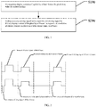
- the present disclosure provides a preconfigured reverse driving method applied in a video displaying process, wherein, as shown in FIG. 1 , includes the steps:
- the display panel may pre-acquire the display content of the plurality of later frames for pixels by content loading; that is, the display panel can acquire the display content of a plurality of frames after the current image when playing the current image.
- an example illustrates acquiring the display content of the four later frames for pixels, as shown in FIG.2 , in the acquired four-frame display content, there is no preconfigured reverse driving signal in the forward driving signal in the upper portion of FIG. 2 while there is preconfigured reverse driving signal before the forward driving signal in the lower portion of FIG. 2 .
- the accumulation of electric charges during video displaying can be suppressed in advance, by adding a reverse driving signal before the forward driving signal, to improve the lifetime of the video display panel and the brightness of the video display.
- the reverse driving signal is also applied when a pixel is not yet illuminated, because in the video displaying process, the content of several frames after the current image can be acquired in advance by content loading; that is, during the video displaying process of the display panel, information on which pixels will be illuminated and which pixels will not be illuminated in subsequent images can be pre-acquired.
- adding a reverse driving signal in advance to unilluminated pixels in the subsequent images can suppress the accumulation of electric charges of pixels in the video display panel in advance accordingly.
- an intensity of the reverse driving signal is proportional to an intensity of the forward driving signal.
- the intensity of the forward driving signal may be divided into levels 0-225, and the reverse driving signal is proportional to levels 0-225; the reverse driving signal is lower than a breakdown signal of the video display panel. That is, more electric charges are accumulated in the potential well when the forward driving signal is strong, and hence, a strong reverse driving signal is needed to suppress and eliminate the accumulated electric charges to improve the lifetime of the video display panel accordingly.
- the forward driving signal of the first frame image is stronger than the forward driving signal of the second frame image or the forward driving signal of the fourth frame image, and therefore, the reverse driving signal of the first frame image is correspondingly stronger than the reverse driving signal of the second frame image or the reverse driving signal of the fourth frame image.
- a reverse driving signal can still be applied to the third frame image, thereby suppressing the accumulation of electric charges in advance.
- the reverse driving signal is one of: a reverse voltage, a reverse current, or an alternation of the reverse voltage and the reverse current.
- the forward driving signal drives a pre-played video display content
- applying a reverse voltage, a reverse current, or an alternation of the reverse voltage and the reverse current to the video display panel.
- the applied reverse driving signal is a reverse voltage
- pixels on the video display panel are in a certain reverse electric field.
- the electric charges accumulated near the interface can be driven to outside the device by the reverse electric field.
- a barrier of the defect potential well may be changed, so that electric charges confined in the potential well can escape, thereby reducing the density of confined electric charges.
- the adjustment of the strength of the reverse electric field can be performed by adjusting a time for the reverse voltage, a frequency of the reverse voltage, and an amplitude of the reverse voltage.
- a percentage of a time for the applied reverse voltage in a cycle, r is 1%-99%; and the time for the reverse voltage, the application time, can affect brightness and driving mode of the video display.
- the percentage of the time for the reverse voltage in a cycle, r can be set to 10% to 60%, and the selection of this range does not affect the brightness and the driving mode, and can effectively provide the required voltage for recovery.
- the frequency of the applied reverse voltage should be not less than 60 Hz; preferably, the frequency of the reverse voltage can be set to 60 to 240 Hz because when the frequency of the reverse voltage is higher 240 Hz, the complexity of the circuit can be increased, the cost can be increased, and the required direction driving load can be too large.
- the amplitude of the applied reverse voltage is -0.1 V to -10 V.
- the amplitude of the reverse voltage can be set to - 1 V to -5 V, and the voltage in this amplitude range can be provided by existing circuit board; no need to replace the circuit board. Meanwhile, the voltage amplitude cannot be too low, the elimination effect of the electric charges can be affected when the voltage is lower than -1V.
- the reverse driving voltage should be less than the breakdown voltage of the video display panel.
- the applied reverse drive signal is a reverse current
- the reverse current injects certain electrons and holes into pixels on the video display panel, thereby neutralizing the counter-type carriers confined in the pixels, thereby reducing the density of the confined electric charges.
- the percentage of the time for the reverse current in a cycle is controlled to be 1% to 99%; preferably, the percentage of the time for the reverse current in a cycle, r, can be set to 10% to 60%, the selection of this range does not affect the brightness and the driving mode, and can provide the required current for recovery.
- the frequency of the reverse current is controlled to be not less than 60 Hz; preferably, the frequency of the reverse current is set to 60 to 240 Hz.
- the frequency of the reverse current is higher than 240 Hz, the complexity of the circuit can be increased, the cost can be increased, and the required direction driving load can be too large.
- the amplitude of the applied reverse current is controlled to be -0.0001 Am/cm -2 to -1 Am/cm -2 .
- the amplitude of the reverse current is set to -0.0001 Am/cm -2 to -0.1 Am/cm -2 because current that is too small results in unapparent electric charge elimination effect.
- the reverse current should be lower than the breakdown current of the video display panel to ensure that the device will not be burned out.
- the waveform of the reverse voltage is one of: a square wave, a triangular wave, a ramp wave or a sine wave; the waveform of the reverse current may also be one of: a square wave, a triangular wave, a ramp wave or a sine wave.
- the driving method of the video display panel will be further explained by specific embodiments.
- the reverse driving signal is a square wave reverse voltage
- the reverse voltage follows a forward driving signal closely, and the reverse voltage is lower than a breakdown voltage of the video display panel; the reverse driving signal and the forward driving signal constitute a driving cycle.
- a percentage of a time for the reverse voltage in a cycle, r, is 1%-99%; a frequency of the reverse voltage, f, is not less than 60 Hz; and an amplitude of the reverse voltage, Vre, is -0.1V to -10V.
- suitable percentage, frequency and amplitude within the range can be selected according to the actual situation to achieve an optimal improved effect.
- the reverse drive signal is a square wave reverse voltage, as shown in FIG. 6 , there is a vacant driving signal in the middle of the reverse driving signal; that is, the reverse voltage follows a forward driving signal closely or follows a vacant driving signal closely; specifically, the reverse driving signal, the forward driving signal, and the vacant driving signal constitute a driving cycle.
- a percentage of a time for the reverse voltage following the forward drive signal in a cycle is ra; a percentage of a for the reverse voltage following the vacant driving voltage in a cycle is rb; the percentage of a time for the vacant driving signal is r0; and a percentage of a time for the reverse driving signal in a cycle, ra+rb, is 1%-99%; a frequency of the reverse voltage, f, is not less than 60 Hz; and an amplitude of the reverse voltage, Vre, is -0.1 V to -10 V.
- suitable percentage, frequency and amplitude within the range can be selected according to actual conditions to achieve optimal improved effect.
- the frequency of the reverse voltage, f is 100 Hz
- the percentage of the time for the reverse voltage following the forward driving signal in a cycle, ra is 0%
- the percentage of the time for the reverse voltage following the vacant driving signal in a cycle, rb is 20%
- the percentage of the time for the vacant driving signal in a cycle, r0 is 15%
- the amplitude of the reverse voltage, Vre is -3V.
- an actual lifetime decay curve of a video display panel driven by the reverse voltage is longer than a lifetime decay curve of the video display panel without a reverse voltage applied, and the degree of attenuation thereof is significantly reduced.
- the reverse drive signal is a square wave reverse current
- the reverse current follows a forward driving signal closely, and the reverse current is less than a breakdown current of the video display panel, the reverse driving signal and the forward driving signal constitute a driving cycle.
- a percentage of a time for the reverse current in a cycle, r, is 1%-99%; a frequency of the reverse current, f, is not less than 60Hz; and an amplitude of the reverse current, Ire, is -0.0001 Am/cm -2 to -1 Am/cm -2 .
- suitable percentage, frequency and amplitude within the range can be selected according to the actual situation to achieve an optimal improved effect.
- the reverse driving signal When the reverse driving signal is a square wave reverse current, as shown in FIG. 10 , there is a vacant driving signal in the middle of the reverse driving signal, and the reverse driving signal may follow a forward driving signal closely or follow a vacant driving signal closely.
- the reverse driving signal, the forward driving signal, and the vacant driving signal constitute a driving cycle.
- a percentage of a time for the reverse current following the forward driving signal in a cycle is ra; a percentage of a time for the reverse current following the vacant driving signal in a cycle is rb; a percentage of a time for the vacant drive signal in a cycle is r0; and a percentage of a time for the reverse driving signal in a cycle, ra+rb, is 1%-99%.
- a frequency of the reverse current, f is not less than 60 Hz
- an amplitude of the reverse current, Ire is -0.0001 Am/cm -2 to -1 Am/cm -2 .
- suitable percentage, frequency and amplitude within the range may be selected according to actual situation to achieve an optimal improved effect.
- the frequency of the reverse current, f is 120 Hz
- the percentage of the time for the reverse current following the forward driving signal in a cycle, ra is 30%
- the percentage of the time for the reverse current following the vacant driving signal in a cycle, rb is 0%
- the percentage of the time for the vacant driving signal in a cycle, r0 is 15%
- the amplitude of the reverse current, Ire is -0.002 Am/cm -2 , as shown in FIG. 11
- an actual lifetime decay curve of a video display panel driven by the reverse voltage is longer than a lifetime decay curve of the video display panel without a reverse current applied, and the degree of attenuation thereof is significantly reduced.
- the reverse driving signal is an alternation of a square wave reverse voltage and a square wave reverse current, and the reverse driving signal does not have a vacant driving signal, as shown in FIG. 12 , the reverse voltage is lower than a breakdown voltage of the video display panel, the reverse current is less than a breakdown current of the video display panel.
- a percentage of a time for the reverse voltage in a cycle is rV; a percentage of the time for the reverse current in a cycle is rI; a percentage of a sum of a time for the reverse voltage and a time for the reverse current in a cycle is 1%-99%;
- a driving frequency, f is not less than 60 Hz;
- an amplitude of the reverse voltage, Vre is -0.1V to -10V;
- an amplitude of the reverse current, Ire is -0.0001 Am/cm -2 to -1 Am/cm -2 .
- the driving frequency, f is 80 Hz
- the percentage of the time for the reverse current in a cycle is 50%
- the amplitude of the reverse current, Ire is -0.001 Am/cm -2
- the time for the reverse voltage in a cycle, rV is 40%
- the amplitude of the reverse voltage is -3V.
- an actual lifetime decay curve of a video display panel with reverse driving is longer than a lifetime decay curve of the video display panel without a reverse driving signal applied, and the degree of the attenuation thereof is significantly reduced.
- the reverse driving signal is an alternation of a square wave reverse voltage and a square wave reverse current, and there is a vacant driving signal in the reverse driving signal, as shown in FIG. 14 , the reverse driving signal, the forward driving signal and the vacant driving signal constitute a driving cycle.
- a percentage of a time for the reverse voltage in a cycle is rV; a percentage of a time for the reverse current is rI; a percentage of a sum of a time for the reverse voltage and a time for the reverse current in a cycle, rV+rI, is 1%-99%; a percentage of a time for the vacant driving signal in a cycle is r0; an amplitude of the reverse voltage, Vre, is -0.1V to -10V; an amplitude of the reverse current, Ire, is -0.0001 Am/cm -2 to -1 Am/cm -2 .
- suitable percentage, frequency and amplitude within the range can be selected according to the actual situation to achieve an optimal improved effect.
- the frequency of the reverse current, f is 120 Hz
- the percentage of the time for the reverse current following the forward driving signal in a cycle, rI is 30%
- the percentage of the time for the reverse voltage following the vacant driving signal in a cycle, rV is 10%
- the percentage of the time for the vacant driving signal in a cycle, r0 is 15%
- the amplitude of the reverse current, Ire is -0.002 Am/cm -2
- the amplitude of the reverse voltage is -2 V
- an actual lifetime decay curve of a video display panel driven with a reverse voltage is longer than a lifetime decay curve of the video display panel without a reverse driving signal applied, and the degree of attenuation thereof is significantly reduced.
- the reverse driving signal is a triangular wave reverse voltage
- the triangular wave reverse voltage follows a forward driving signal closely, and the reverse voltage is lower than a breakdown voltage of the video display panel.
- the waveform of the reverse voltage is a triangular wave, in the rising phase, the reverse voltage becomes larger as time passes; on the contrary, in the falling phase, the reverse voltage becomes lower as time passes.
- the dynamic voltage mode effectively reduces the load on the video display panel, enabling a small capacitive and inductive reactance.
- the reverse driving signal and the forward driving signal constitute a driving cycle.
- a percentage of a time for the reverse voltage in a cycle, r, is 1%-99%; a frequency of the reverse voltage, f, is not less than 60Hz; and an amplitude of the reverse voltage, Vre, is -0.1V to -10V.
- suitable percentage, frequency and amplitude within the range can be selected according to the actual situation to achieve an optimal improved effect.
- the frequency of the reverse voltage, f is 60 Hz
- the percentage of the time for the reverse voltage in a cycle, r is 50%
- the amplitude of the reverse voltage, Vre is -3 V, as shown in FIG. 17
- an actual lifetime decay curve of a video display panel driven by a triangular reverse voltage is longer than a lifetime decay curve of the video display panel without the reverse voltage applied, and the degree of attenuation thereof is significantly reduced.
- a peak value of the triangular wave is Vtr; a percentage of a time for the reverse voltage in a cycle, r, is 1%-99%; a frequency of the reverse voltage, f, is not less than 60Hz; and an amplitude of the reverse voltage Vre+Vtr, is -0.1V to -10V.
- suitable percentage, frequency and amplitude within the range can be selected according to actual situation to achieve an optimal improved effect.
- a peak value of the ramp is Vtr, the value of may be positive or negative; a percentage of a time for the reverse voltage, r, is 1%-99%; a frequency of the reverse voltage, f, is not less than 60 Hz; and an amplitude of the reverse voltage, Vr+Vtr, is -0.1V to -10V.
- suitable percentage, frequency and amplitude within the range can be selected according to actual situation to achieve an optimal improved effect.
- the sine wave reverse voltage follows a forward driving signal closely, and the reverse voltage is lower than a breakdown voltage of the video display panel.
- the sine wave reverse driving signal and the forward driving signal constitute a driving cycle; a percentage of the time for the sine wave reverse voltage in a cycle, r, is 1%-99%; a frequency of the reverse voltage, f, is not less than 60Hz; an amplitude of the reverse voltage, Vre, is -0.1V to -10V.
- suitable percentage, frequency and amplitude within the range can be selected according to actual situation to achieve an optimal improved effect.
- the present disclosure provides a preconfigured reverse driving method applied in a video displaying process, pre-acquiring display contents of a plurality of later frames for pixels which are already lit in a video by content loading; adding a reverse driving signal before each forward driving signals for driving the display content of the plurality of frames, to suppress accumulation of electric charges on pixels in a video display panel in advance; the reverse driving signal changes the barrier of the defect potential well, eliminating the electric charges confined and accumulated in the potential well, reducing the density of the confined electric charges, thereby increasing the brightness of the video display and extending the lifetime of the video display panel.
Landscapes
- Engineering & Computer Science (AREA)
- Physics & Mathematics (AREA)
- Computer Hardware Design (AREA)
- General Physics & Mathematics (AREA)
- Theoretical Computer Science (AREA)
- Multimedia (AREA)
- Control Of Indicators Other Than Cathode Ray Tubes (AREA)
- Control Of El Displays (AREA)
- Electroluminescent Light Sources (AREA)
Abstract
Description
- The present disclosure relates to the field of display panels, and in particular relates to a preset reverse driving method applied in a video display process.
- The lifetime of quantum dot light-emitting diodes (QLEDs) has always been a bottleneck restricting its wide application. In addition to optimizing materials, devices, and fabrication processes, driving quantum dot light-emitting diodes may also be an approach to decrease the attenuation of the QLEDs and enhance the lifetime of the QLEDs.
- A quantum dot light-emitting diode is generally composed of a first electrode, a hole transport layer, a quantum dot light-emitting layer, an electron transport layer, and a second electrode. Since different layers have different energy levels (that is, there exists an energy level difference), during operation, electric charges accumulate at the interface between two energy levels, especially the interface in contact with the quantum dot light-emitting layer. This can greatly affect the luminescent properties of the quantum dots, thereby reducing the luminous intensity; and these defects also limit the carriers. As the operating time of a quantum dot light-emitting diode increases, more and more electric charges are confined to the interface, which serves as the center of quenching photons, thereby greatly reducing the luminous intensity and shortening the lifetime of quantum dot light-emitting diodes.
- Also, in a video display process, when the LED in the display panel is a quantum dot light-emitting diode, the accumulation of charges may seriously affect the brightness of the video display and the lifetime of the video display panel when driving the video content display.
- Therefore, the above technology has yet to be improved and developed.
- In view of the above deficiencies of the prior art, an objective of the present disclosure is to provide a preconfigured reverse driving method applied in a video display process, which aims to solve the problem that the video display brightness and the lifetime of the video display panel is seriously affected by long-time accumulation of electric charges in existing video displaying processes.
- The technical solutions of the present disclosure are as follows:
A preconfigured reverse driving method applied in a video displaying process, comprising the steps of: - Step A: Pre-acquiring display content of a plurality of later frames for pixels in the video by content loading;
- Step B: Adding a reverse driving signal before each forward driving signal for driving the display content of the plurality of frames, to suppress accumulation of electric charges on the pixels in the video display panel in advance.
- In the preconfigured reverse driving method applied in a video displaying process, the intensity of the reverse driving signal is proportional to the intensity of the forward driving signal.
- In the preconfigured reverse driving method applied in a video displaying process, the reverse driving signal is one of: a reverse voltage, a reverse current, or an alternation of the reverse voltage and the reverse current.
- In the preconfigured reverse driving method applied in a video displaying process, the reverse voltage is lower than a breakdown voltage of a video display panel.
- In the preconfigured reverse driving method applied in a video displaying process, the reverse current is lower than a breakdown current of a video display panel.
- In the preconfigured reverse driving method applied in a video displaying process, the waveform of the reverse driving signal is at least one of: a square wave, a triangular wave, a ramp wave or a sine wave.
- In the preconfigured reverse driving method applied in a video displaying process, when the reverse driving signal is an alternation of the reverse voltage and the reverse current, a percentage of a sum of a time for the reverse voltage and a time for the reverse current in a cycle is 1% to 99%.
- In the preconfigured reverse driving method applied in a video displaying process, the reverse driving signal and the forward driving signal constitute a driving cycle, when the reverse driving signal is an alternation of the reverse voltage and the reverse current, a percentage of a sum of a time for the reverse voltage and a time for the reverse current in a cycle is 10% to 60%.
- In the preconfigured reverse driving method applied in a video displaying process, the reverse driving signal and the forward driving signal constitute a driving cycle, when the reverse driving signal is a reverse voltage, a percentage of a time for the reverse voltage in a cycle is 1% to 99%; or a frequency of the reverse voltage is not less than 60 Hz; or an amplitude of the reverse voltage is -0.1V to -10V.
- In the preconfigured reverse driving method applied in a video displaying process, the reverse driving signal and the forward driving signal constitute a driving cycle, when the reverse driving signal is a reverse voltage, a percentage of a time for the reverse voltage in a cycle is 10% to 60%; or t frequency of the reverse voltage is 60-240 Hz; or the magnitude of the reverse voltage is -1V to -5V.
- In the preconfigured reverse driving method applied in a video displaying process, the reverse driving signal and the forward driving signal constitute a driving cycle. When the reverse driving signal is a reverse current, a percentage of a time for the current in a cycle is 1% to 99%; the frequency of the reverse current is not less than 60 Hz; or the magnitude of the reverse current is -0.0001 Am/cm-2 to -1 Am/cm-2.
- In the preconfigured reverse driving method applied in a video displaying process, the reverse driving signal and the forward driving signal constitute a driving cycle. When the reverse driving signal is a reverse current, a percentage of a time for the reverse current in a cycle is 10% to 60%; or the frequency of the reverse current is 60-240 Hz; or the magnitude of the reverse current is -0.0001 Am/cm-2 to -0.1 Am/cm-2.
- In the method applied in a preconfigured reverse driving method in a video displaying process, a vacant driving signal is in the middle of the reverse driving signal.
- In the preconfigured reverse driving method applied in the video displaying process, the reverse driving signal, the forward driving signal and the vacant driving signal constitute a driving cycle, and the percentage of the time for the vacant driving signal in a cycle is 0 %-15%.
- In the preconfigured reverse driving method applied in a video displaying process, the reverse driving signal, the forward driving signal, and the vacant driving signal constitute a driving cycle. When the reverse driving signal is an alternation of the reverse voltage and the reverse current, the percentage of a sum of a time for the reverse voltage and a time for the reverse current in a cycle is 1% to 99%.
- In the preconfigured reverse driving method applied in a video displaying process, wherein the reverse driving signal, the forward driving signal, and the vacant driving signal constitute a driving cycle. When the reverse driving signal is an alternation of the reverse voltage and the reverse current, the sum of a time for the reverse voltage and the percentage of a time for the reverse current in a cycle is 10% to 60%.
- In the preconfigured reverse driving method applied in a video displaying process, the reverse driving signal, the forward driving signal, and the vacant driving signal constitute a driving cycle. When the reverse driving signal is a reverse voltage, the percentage of the time for the reverse voltage in a cycle is 1% to 99%; or the frequency of the reverse voltage is not less than 60 Hz; or the magnitude of the reverse voltage is -0.1V to -10V.
- In the preconfigured reverse driving method applied in a video displaying process, the reverse driving signal, the forward driving signal, and the vacant driving signal constitute a driving cycle. When the reverse driving signal is a reverse voltage, the percentage of the time for the reverse voltage in a cycle is 10%-60%; or the frequency of the reverse voltage is between 60 Hz and 240 Hz; or the amplitude of the reverse voltage is -1V to -5V.
- In the preconfigured reverse driving method applied in a video displaying process, the reverse driving signal, the forward driving signal, and the vacant driving signal constitute a driving cycle, when the reverse driving signal is a reverse current, a percentage of the time for the reverse current in a cycle is 1%-99%; or a frequency of the reverse current is not less than 60 Hz; or the amplitude of the reverse current is -0.0001 Am/cm-2 to -1Am/cm-2.
- In the preconfigured reverse driving method applied in a video displaying process, the reverse driving signal, the forward driving signal, and the vacant driving signal constitute a driving cycle, when the reverse driving signal is a reverse current, the percentage of the time for the reverse current in a cycle is 10%-60% of the cycle; or a frequency of the reverse current is 60 to 240 Hz; or an amplitude of the reverse current is -0.0001 Am/cm-2 to -0.1 Am/cm-2.
- Advantageous Effects: The present disclosure provides a preconfigured reverse driving method applied in a video displaying process: pre-acquiring display content of a plurality of later frames for pixels in a video by content loading; adding a reverse driving signal before each forward driving signal for driving the display content of the plurality of frames, to suppress accumulation of electric charges on pixels in a video display panel in advance. The reverse driving signal changes the barrier of the defect potential well, eliminates confinement and accumulation of the electric charges in the potential well, reduces the density of the electric charges, which increases the brightness of the video display and extends the lifetime of the video display panel.
-
-
FIG. 1 is a flow chart of an embodiment of a preconfigured reverse driving method applied in a video displaying process of the present disclosure; -
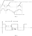
FIG. 2 is a first comparative diagram of with versus without a reverse driving signal being applied according to the present disclosure; -
FIG. 3 is a second comparative diagram of with versus without a reverse driving signal being applied according to the present disclosure; -
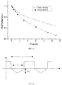
FIG. 4 is of a waveform diagram of a driving signal in Embodiment One of the present disclosure; -
FIG. 5 is a comparison diagram of a lifetime decay curve of a video display panel driven by a reverse driving signal and a lifetime decay curve of a normally driven video display panel in Embodiment One of the present disclosure; -
FIG. 6 is a waveform diagram of a driving signal in Embodiment Two of the present disclosure; -
FIG. 7 is a comparison diagram of a lifetime decay curve of a video display panel driven by a reverse driving signal and a lifetime decay curve of a normally driven video display panel in Embodiment Two of the present disclosure; -
FIG. 8 is a waveform diagram of a driving signal in Embodiment Three of the present disclosure; -
FIG. 9 is a comparison diagram of a lifetime decay curve of a video display panel driven by a reverse driving signal and a lifetime decay curve of a normally driven video display panel in Embodiment Three of the present disclosure; -
FIG. 10 is a waveform diagram of a driving signal in Embodiment Four of the present disclosure; -
FIG. 11 is a comparison diagram of a lifetime decay curve of a video display panel driven by a reverse driving signal and a lifetime decay curve of a normally driven video display panel in Embodiment Four of the present disclosure; -
FIG. 12 is a waveform diagram of a driving signal in Embodiment Five of the present disclosure; -
FIG. 13 is a comparison diagram of a lifetime decay curve of a video display panel driven by a reverse drive signal and a lifetime decay curve of a normally driven video display panel in Embodiment Five of the present disclosure; -
FIG. 14 is a waveform diagram of a driving signal in Embodiment Six of the present disclosure; -
FIG. 15 is a comparison diagram of a lifetime decay curve of a video display panel driven by a reverse driving signal and a lifetime decay curve of a normally driven video display panel in Embodiment Six of the present disclosure; -
FIG. 16 is a waveform diagram of a driving signal in Embodiment Seven of the present disclosure; -
FIG. 17 is a comparison diagram of a lifetime decay curve of a video display panel driven by a reverse driving signal and a lifetime decay curve of a normally driven video display panel in Embodiment Seven of the present disclosure; -
FIG. 18 is a waveform diagram of a driving signal in Embodiment Eight of the present disclosure; -
FIG. 19 is a comparison diagram of a lifetime decay curve of a video display panel driven by a reverse drive signal and a lifetime decay curve of a normally driven video display panel in Embodiment Eight of the present disclosure; -
FIG. 20 is a waveform diagram of a driving signal in Embodiment Nine of the present disclosure; -
FIG. 21 is a comparison diagram of a lifetime decay curve of a video display panel driven by a reverse driving signal and a lifetime decay curve of a normally driven video display panel in Embodiment Nine of the present disclosure; -
FIG. 22 is a waveform diagram of a driving signal in Embodiment Ten of the present disclosure; and -
FIG. 23 is a comparison diagram of a lifetime decay curve of a video display panel driven by a reverse driving signal and a lifetime decay curve of a normally driven video display panel in Embodiment Ten of the present disclosure. - The present disclosure provides a preconfigured reverse driving method applied in a video display process. In order to make the objects, technical solutions and effects of the present disclosure clear, the present disclosure will be further described in detail below. It is understood that the specific embodiments described herein are merely illustrative of the present disclosure and are not intended to limit the present disclosure.
- The present disclosure provides a preconfigured reverse driving method applied in a video displaying process, wherein, as shown in
FIG. 1 , includes the steps: - S100: Pre-acquiring display content of a plurality of later frames for video pixels by content loading;
- S200: Adding a reverse driving signal before each forward driving signal for driving the display content of the plurality of frames, to suppress accumulation of electric charges on pixels in a video display panel in advance.
- Specifically, in a display mode of a fixed content such as a movie video, the display panel may pre-acquire the display content of the plurality of later frames for pixels by content loading; that is, the display panel can acquire the display content of a plurality of frames after the current image when playing the current image. In the present disclosure, an example illustrates acquiring the display content of the four later frames for pixels, as shown in
FIG.2 , in the acquired four-frame display content, there is no preconfigured reverse driving signal in the forward driving signal in the upper portion ofFIG. 2 while there is preconfigured reverse driving signal before the forward driving signal in the lower portion ofFIG. 2 . In the present disclosure, the accumulation of electric charges during video displaying can be suppressed in advance, by adding a reverse driving signal before the forward driving signal, to improve the lifetime of the video display panel and the brightness of the video display. - Further, the reverse driving signal is also applied when a pixel is not yet illuminated, because in the video displaying process, the content of several frames after the current image can be acquired in advance by content loading; that is, during the video displaying process of the display panel, information on which pixels will be illuminated and which pixels will not be illuminated in subsequent images can be pre-acquired. Based on the above, in the present disclosure, adding a reverse driving signal in advance to unilluminated pixels in the subsequent images, can suppress the accumulation of electric charges of pixels in the video display panel in advance accordingly.
- Further, as shown in
FIG. 2 , an intensity of the reverse driving signal is proportional to an intensity of the forward driving signal. For example, the intensity of the forward driving signal may be divided into levels 0-225, and the reverse driving signal is proportional to levels 0-225; the reverse driving signal is lower than a breakdown signal of the video display panel. That is, more electric charges are accumulated in the potential well when the forward driving signal is strong, and hence, a strong reverse driving signal is needed to suppress and eliminate the accumulated electric charges to improve the lifetime of the video display panel accordingly. As shown inFIG. 2 , the forward driving signal of the first frame image is stronger than the forward driving signal of the second frame image or the forward driving signal of the fourth frame image, and therefore, the reverse driving signal of the first frame image is correspondingly stronger than the reverse driving signal of the second frame image or the reverse driving signal of the fourth frame image. - Further, as shown in
FIG. 3 , in the third frame image, although there is no forward driving signal, a reverse driving signal can still be applied to the third frame image, thereby suppressing the accumulation of electric charges in advance. - Further, in the present disclosure, the reverse driving signal is one of: a reverse voltage, a reverse current, or an alternation of the reverse voltage and the reverse current.
- Specifically, when the forward driving signal drives a pre-played video display content, applying a reverse voltage, a reverse current, or an alternation of the reverse voltage and the reverse current, to the video display panel.
- When the applied reverse driving signal is a reverse voltage, pixels on the video display panel are in a certain reverse electric field. In the reverse electric field, the electric charges accumulated near the interface can be driven to outside the device by the reverse electric field. In addition, by adjusting an intensity of the reverse electric field, a barrier of the defect potential well may be changed, so that electric charges confined in the potential well can escape, thereby reducing the density of confined electric charges.
- The adjustment of the strength of the reverse electric field can be performed by adjusting a time for the reverse voltage, a frequency of the reverse voltage, and an amplitude of the reverse voltage.
- Specifically, a percentage of a time for the applied reverse voltage in a cycle, r, is 1%-99%; and the time for the reverse voltage, the application time, can affect brightness and driving mode of the video display. Preferably, the percentage of the time for the reverse voltage in a cycle, r, can be set to 10% to 60%, and the selection of this range does not affect the brightness and the driving mode, and can effectively provide the required voltage for recovery.
- Specifically, for the frequency of the reverse voltage, the frequency of the applied reverse voltage should be not less than 60 Hz; preferably, the frequency of the reverse voltage can be set to 60 to 240 Hz because when the frequency of the reverse voltage is higher 240 Hz, the complexity of the circuit can be increased, the cost can be increased, and the required direction driving load can be too large.
- Specifically, for the amplitude of the reverse voltage, the amplitude of the applied reverse voltage is -0.1 V to -10 V. Preferably, the amplitude of the reverse voltage can be set to - 1 V to -5 V, and the voltage in this amplitude range can be provided by existing circuit board; no need to replace the circuit board. Meanwhile, the voltage amplitude cannot be too low, the elimination effect of the electric charges can be affected when the voltage is lower than -1V. The reverse driving voltage should be less than the breakdown voltage of the video display panel.
- When the applied reverse drive signal is a reverse current, the reverse current injects certain electrons and holes into pixels on the video display panel, thereby neutralizing the counter-type carriers confined in the pixels, thereby reducing the density of the confined electric charges.
- Specifically, for the time for the applied reverse current, the percentage of the time for the reverse current in a cycle is controlled to be 1% to 99%; preferably, the percentage of the time for the reverse current in a cycle, r, can be set to 10% to 60%, the selection of this range does not affect the brightness and the driving mode, and can provide the required current for recovery.
- Specifically, for the frequency of the reverse current, the frequency of the reverse current is controlled to be not less than 60 Hz; preferably, the frequency of the reverse current is set to 60 to 240 Hz. When the frequency of the reverse current is higher than 240 Hz, the complexity of the circuit can be increased, the cost can be increased, and the required direction driving load can be too large.
- Specifically, for the amplitude of the reverse current, the amplitude of the applied reverse current is controlled to be -0.0001 Am/cm-2 to -1 Am/cm-2. Preferably, the amplitude of the reverse current is set to -0.0001 Am/cm-2 to -0.1 Am/cm-2 because current that is too small results in unapparent electric charge elimination effect. Meanwhile, the reverse current should be lower than the breakdown current of the video display panel to ensure that the device will not be burned out.
- Further, in the present disclosure, the waveform of the reverse voltage is one of: a square wave, a triangular wave, a ramp wave or a sine wave; the waveform of the reverse current may also be one of: a square wave, a triangular wave, a ramp wave or a sine wave.
- The driving method of the video display panel will be further explained by specific embodiments.
- When the reverse driving signal is a square wave reverse voltage, as shown in
FIG. 4 , the reverse voltage follows a forward driving signal closely, and the reverse voltage is lower than a breakdown voltage of the video display panel; the reverse driving signal and the forward driving signal constitute a driving cycle. A percentage of a time for the reverse voltage in a cycle, r, is 1%-99%; a frequency of the reverse voltage, f, is not less than 60 Hz; and an amplitude of the reverse voltage, Vre, is -0.1V to -10V. In specific implementation, suitable percentage, frequency and amplitude within the range can be selected according to the actual situation to achieve an optimal improved effect. - Specifically, when the frequency of the reverse voltage, f, is 60 Hz, the percentage of the time for the reverse voltage in a cycle, r, is 50%, and the amplitude of the reverse voltage, Vre, is -3 V, as shown in
FIG. 5 , an actual lifetime decay curve of a video display panel driven by a reverse voltage is longer than an lifetime decay curve of the video display panel without a reverse voltage applied, and the degree of attenuation thereof is significantly reduced. - When the reverse drive signal is a square wave reverse voltage, as shown in
FIG. 6 , there is a vacant driving signal in the middle of the reverse driving signal; that is, the reverse voltage follows a forward driving signal closely or follows a vacant driving signal closely; specifically, the reverse driving signal, the forward driving signal, and the vacant driving signal constitute a driving cycle. A percentage of a time for the reverse voltage following the forward drive signal in a cycle is ra; a percentage of a for the reverse voltage following the vacant driving voltage in a cycle is rb; the percentage of a time for the vacant driving signal is r0; and a percentage of a time for the reverse driving signal in a cycle, ra+rb, is 1%-99%; a frequency of the reverse voltage, f, is not less than 60 Hz; and an amplitude of the reverse voltage, Vre, is -0.1 V to -10 V. In specific implementation, suitable percentage, frequency and amplitude within the range can be selected according to actual conditions to achieve optimal improved effect. - Specifically, when the frequency of the reverse voltage, f, is 100 Hz, the percentage of the time for the reverse voltage following the forward driving signal in a cycle, ra, is 0%; the percentage of the time for the reverse voltage following the vacant driving signal in a cycle, rb, is 20%; the percentage of the time for the vacant driving signal in a cycle, r0, is 15%; and the amplitude of the reverse voltage, Vre, is -3V. As shown in
FIG. 7 , an actual lifetime decay curve of a video display panel driven by the reverse voltage is longer than a lifetime decay curve of the video display panel without a reverse voltage applied, and the degree of attenuation thereof is significantly reduced. - When the reverse drive signal is a square wave reverse current, as shown in
FIG. 8 , the reverse current follows a forward driving signal closely, and the reverse current is less than a breakdown current of the video display panel, the reverse driving signal and the forward driving signal constitute a driving cycle. A percentage of a time for the reverse current in a cycle, r, is 1%-99%; a frequency of the reverse current, f, is not less than 60Hz; and an amplitude of the reverse current, Ire, is -0.0001 Am/cm-2 to -1 Am/cm-2. In specific implementation, suitable percentage, frequency and amplitude within the range can be selected according to the actual situation to achieve an optimal improved effect. - Specifically, when the frequency of the reverse current, f, is 60 Hz, the percentage of the time for the reverse current in a cycle, r, is 50%, and the amplitude of the reverse current, Ire, is -0.001 Am/cm-2, as shown in
FIG. 9 , an actual lifetime decay curve of a video display panel driven by a reverse current is longer than a lifetime decay curve of the video display panel without a reverse current applied, and the degree of attenuation thereof is significantly reduced. - When the reverse driving signal is a square wave reverse current, as shown in
FIG. 10 , there is a vacant driving signal in the middle of the reverse driving signal, and the reverse driving signal may follow a forward driving signal closely or follow a vacant driving signal closely. Specifically, the reverse driving signal, the forward driving signal, and the vacant driving signal constitute a driving cycle. A percentage of a time for the reverse current following the forward driving signal in a cycle is ra; a percentage of a time for the reverse current following the vacant driving signal in a cycle is rb; a percentage of a time for the vacant drive signal in a cycle is r0; and a percentage of a time for the reverse driving signal in a cycle, ra+rb, is 1%-99%. A frequency of the reverse current, f, is not less than 60 Hz, and an amplitude of the reverse current, Ire, is -0.0001 Am/cm-2 to -1 Am/cm-2. In specific implementation, suitable percentage, frequency and amplitude within the range may be selected according to actual situation to achieve an optimal improved effect. - Specifically, when the frequency of the reverse current, f, is 120 Hz, and the percentage of the time for the reverse current following the forward driving signal in a cycle, ra, is 30%; the percentage of the time for the reverse current following the vacant driving signal in a cycle, rb, is 0%; the percentage of the time for the vacant driving signal in a cycle, r0, is 15%; and the amplitude of the reverse current, Ire, is -0.002 Am/cm-2, as shown in
FIG. 11 , an actual lifetime decay curve of a video display panel driven by the reverse voltage is longer than a lifetime decay curve of the video display panel without a reverse current applied, and the degree of attenuation thereof is significantly reduced. - When the reverse driving signal is an alternation of a square wave reverse voltage and a square wave reverse current, and the reverse driving signal does not have a vacant driving signal, as shown in
FIG. 12 , the reverse voltage is lower than a breakdown voltage of the video display panel, the reverse current is less than a breakdown current of the video display panel. A percentage of a time for the reverse voltage in a cycle is rV; a percentage of the time for the reverse current in a cycle is rI; a percentage of a sum of a time for the reverse voltage and a time for the reverse current in a cycle is 1%-99%; a driving frequency, f, is not less than 60 Hz; an amplitude of the reverse voltage, Vre, is -0.1V to -10V; and an amplitude of the reverse current, Ire, is -0.0001 Am/cm-2 to -1 Am/cm-2. - Specifically, when the driving frequency, f, is 80 Hz, the percentage of the time for the reverse current in a cycle is 50%, the amplitude of the reverse current, Ire, is -0.001 Am/cm-2, and the time for the reverse voltage in a cycle, rV, is 40%, and the amplitude of the reverse voltage is -3V. As shown in
Figure 13 , an actual lifetime decay curve of a video display panel with reverse driving is longer than a lifetime decay curve of the video display panel without a reverse driving signal applied, and the degree of the attenuation thereof is significantly reduced. - When the reverse driving signal is an alternation of a square wave reverse voltage and a square wave reverse current, and there is a vacant driving signal in the reverse driving signal, as shown in
FIG. 14 , the reverse driving signal, the forward driving signal and the vacant driving signal constitute a driving cycle. A percentage of a time for the reverse voltage in a cycle is rV; a percentage of a time for the reverse current is rI; a percentage of a sum of a time for the reverse voltage and a time for the reverse current in a cycle, rV+rI, is 1%-99%; a percentage of a time for the vacant driving signal in a cycle is r0; an amplitude of the reverse voltage, Vre, is -0.1V to -10V; an amplitude of the reverse current, Ire, is -0.0001 Am/cm-2 to -1 Am/cm-2. In specific implementation, suitable percentage, frequency and amplitude within the range can be selected according to the actual situation to achieve an optimal improved effect. - Specifically, when the frequency of the reverse current, f, is 120 Hz, the percentage of the time for the reverse current following the forward driving signal in a cycle, rI, is 30%; the percentage of the time for the reverse voltage following the vacant driving signal in a cycle, rV, is 10%; the percentage of the time for the vacant driving signal in a cycle, r0, is 15%; the amplitude of the reverse current, Ire, is -0.002 Am/cm-2; and the amplitude of the reverse voltage is -2 V, as shown in
FIG. 15 , an actual lifetime decay curve of a video display panel driven with a reverse voltage is longer than a lifetime decay curve of the video display panel without a reverse driving signal applied, and the degree of attenuation thereof is significantly reduced. - When the reverse driving signal is a triangular wave reverse voltage, as shown in
FIG. 16 , the triangular wave reverse voltage follows a forward driving signal closely, and the reverse voltage is lower than a breakdown voltage of the video display panel. When the waveform of the reverse voltage is a triangular wave, in the rising phase, the reverse voltage becomes larger as time passes; on the contrary, in the falling phase, the reverse voltage becomes lower as time passes. The dynamic voltage mode effectively reduces the load on the video display panel, enabling a small capacitive and inductive reactance. The reverse driving signal and the forward driving signal constitute a driving cycle. A percentage of a time for the reverse voltage in a cycle, r, is 1%-99%; a frequency of the reverse voltage, f, is not less than 60Hz; and an amplitude of the reverse voltage, Vre, is -0.1V to -10V. In specific implementation, suitable percentage, frequency and amplitude within the range can be selected according to the actual situation to achieve an optimal improved effect. - Specifically, when the frequency of the reverse voltage, f, is 60 Hz, the percentage of the time for the reverse voltage in a cycle, r, is 50%; the amplitude of the reverse voltage, Vre, is -3 V, as shown in
FIG. 17 , an actual lifetime decay curve of a video display panel driven by a triangular reverse voltage is longer than a lifetime decay curve of the video display panel without the reverse voltage applied, and the degree of attenuation thereof is significantly reduced. - When the reverse driving signal is a triangular wave reverse voltage, and the triangular wave reverse voltage is applied to a negative voltage, Vre, as shown in
FIG. 18 , a peak value of the triangular wave is Vtr; a percentage of a time for the reverse voltage in a cycle, r, is 1%-99%; a frequency of the reverse voltage, f, is not less than 60Hz; and an amplitude of the reverse voltage Vre+Vtr, is -0.1V to -10V. In specific implementation, suitable percentage, frequency and amplitude within the range can be selected according to actual situation to achieve an optimal improved effect. - Specifically, when the frequency f of the reverse voltage is 60 Hz, the percentage of the time for the reverse voltage in a cycle is 50%, and the amplitude of the reverse voltage Vre+Vtr is -5 V, as shown in
FIG. 19 , an actual lifetime decay curve of a video display panel driven by a triangular reverse voltage is longer than a lifetime decay curve of the video display panel without the reverse voltage applied, and the degree of attenuation thereof is significantly reduced. - When the reverse driving signal is a ramp reverse voltage and the ramp reverse voltage is applied to a negative voltage, Vre, as shown in
FIG. 20 , a peak value of the ramp is Vtr, the value of may be positive or negative; a percentage of a time for the reverse voltage, r, is 1%-99%; a frequency of the reverse voltage, f, is not less than 60 Hz; and an amplitude of the reverse voltage, Vr+Vtr, is -0.1V to -10V. In specific implementation, suitable percentage, frequency and amplitude within the range can be selected according to actual situation to achieve an optimal improved effect. - Specifically, when the frequency of the reverse voltage, f, is 60 Hz, the percentage of the time for the reverse voltage in a cycle is 50%, and the amplitude of the reverse voltage, Vre+Vtr, is -5 V, as shown in
FIG. 21 , an actual lifetime decay curve of video display panel driven by the ramp reverse voltage is longer than a lifetime decay curve of the video display panel without the reverse voltage applied, and the degree of attenuation thereof is significantly reduced. - When the direction driving signal is a sine wave reverse voltage, as shown in
FIG. 22 , the sine wave reverse voltage follows a forward driving signal closely, and the reverse voltage is lower than a breakdown voltage of the video display panel. The sine wave reverse driving signal and the forward driving signal constitute a driving cycle; a percentage of the time for the sine wave reverse voltage in a cycle, r, is 1%-99%; a frequency of the reverse voltage, f, is not less than 60Hz; an amplitude of the reverse voltage, Vre, is -0.1V to -10V. In specific implementation, suitable percentage, frequency and amplitude within the range can be selected according to actual situation to achieve an optimal improved effect. - Specifically, when the frequency of the reverse voltage, f, is 60 Hz, the percentage of the time for the sine wave reverse voltage, r, is 50%, and the amplitude of the reverse voltage, Vre, is -3 V, as shown in
FIG. 23 , an actual lifetime decay curve of a video display panel driven by a reverse voltage is longer than the lifetime decay curve of the video display panel without the reverse voltage applied, and the degree of attenuation thereof is significantly reduced. - In summary, the present disclosure provides a preconfigured reverse driving method applied in a video displaying process, pre-acquiring display contents of a plurality of later frames for pixels which are already lit in a video by content loading; adding a reverse driving signal before each forward driving signals for driving the display content of the plurality of frames, to suppress accumulation of electric charges on pixels in a video display panel in advance; the reverse driving signal changes the barrier of the defect potential well, eliminating the electric charges confined and accumulated in the potential well, reducing the density of the confined electric charges, thereby increasing the brightness of the video display and extending the lifetime of the video display panel.
- It is to be understood that the application of the present disclosure is not limited to the above-described examples, and those skilled in the art can make modifications and variations in accordance with the above description, all of which are within the scope of the appended claims.
Claims (20)
- A preconfigured reverse driving method applied in a video displaying process, wherein, comprising the steps of:A: pre-acquiring display content of a plurality of later frames for pixels in a video by content loading;B: adding a reverse driving signal before each forward driving signal for driving the display content of the plurality of frames, to suppress accumulation of electric charges on pixels in a video display panel in advance.
- The preconfigured reverse driving method applied in a video displaying process according to claim 1, wherein the intensity of the reverse driving signal is proportional to the intensity of the forward driving signal.
- The preconfigured reverse driving method applied in a video displaying process according to claim 1, wherein the reverse driving signal is one of: a reverse voltage, a reverse current, or an alternation of the reverse voltage and the reverse current.
- The preconfigured reverse driving method applied in a video display process according to claim 3, wherein the reverse voltage is lower than a breakdown voltage of the video display panel.
- The preconfigured reverse driving method applied in a video displaying process according to claim 3, wherein the reverse current is lower than a breakdown current of the video display panel.
- The preconfigured reverse driving method applied in a video displaying process according to claim 3, wherein the waveform of the reverse driving signal is at least one of: a square wave, a triangular wave, a ramp wave, or a sine wave.
- The preconfigured reverse driving method applied in a video displaying process according to claim 3, wherein the reverse driving signal and the forward driving signal constitute a driving cycle, and when the reverse driving signal is an alternation of the reverse voltage and the reverse current, a percentage of a sum of a time for the reverse voltage and a time for the reverse current is 1% to 99%.
- The preconfigured reverse driving method applied in a video displaying process according to claim 7, wherein the reverse driving signal and the forward driving signal constitute a driving cycle, when the reverse driving signal is an alternation of the reverse voltage and the reverse current, the percentage of the sum of the time for the reverse voltage and the time for the reverse current is 10% to 60%.
- The preconfigured reverse driving method applied in a video displaying process according to claim 3, wherein the reverse driving signal and the forward driving signal constitute a driving cycle, and when the reverse driving signal is a reverse voltage, a percentage of a time for the reverse voltage in a cycle is 1% to 99%; or a frequency of the reverse voltage is not less than 60 Hz; or an amplitude of the reverse voltage is -0.1 V to -10V.
- The preconfigured reverse driving method applied in a video displaying process according to claim 3, wherein the reverse driving signal and the forward driving signal constitute a driving cycle, and when the reverse driving signal is a reverse voltage, a percentage of a time for the reverse voltage in a cycle is 10% to 60%; or a frequency of the reverse voltage is 60 to 240 Hz; or an amplitude of the reverse voltage is -1V to -5V.
- The preconfigured reverse driving method applied in a video displaying process according to claim 3, wherein the reverse driving signal and the forward driving signal constitute a driving cycle, and when the reverse driving signal is a reverse current, a percentage of a time for the reverse current in a cycle is 1% to 99%, a frequency of the reverse current is not less than 60 Hz, an amplitude of the reverse current is -0.0001 Am/cm-2 to -1 Am/cm-2.
- The preconfigured reverse driving method applied in a video displaying process according to claim 3, wherein the reverse driving signal and the forward driving signal constitute a driving cycle, and when the reverse driving signal is a reverse current, a percentage of a time for the reverse current in a cycle is 10% to 60%; or a frequency of the reverse current is 60 to 240 Hz; or an amplitude of the reverse current is -0.0001 Am/cm-2 to -0.1Am/cm-2.
- The preconfigured reverse driving method applied in a video displaying process according to claim 1, wherein a vacant driving signal is in the middle of the reverse driving signal.
- The preconfigured reverse driving method applied in a video displaying process according to claim 13, wherein the reverse driving signal, the forward driving signal and the vacant driving signal constitute a driving cycle, and a percentage of a time for the vacant driving signal in a cycle is 0% to 15%.
- The preconfigured reverse driving method applied in a video displaying process according to claim 13, wherein the reverse drive signal, the forward drive signal and the vacant drive signal constitute a drive cycle, when the reverse driving signal is an alternation of a reverse voltage and a reverse current, a percentage of a sum of a time for the reverse voltage and a time for the reverse current in a cycle is 1% to 99%.
- The preconfigured reverse driving method applied in a video displaying process according to claim 13, wherein the reverse driving signal, the forward driving signal and the vacant driving signal constitute a driving cycle, when the reverse driving signal is an alternation of a reverse voltage and a reverse current, a percentage of a sum of a time for the reverse voltage and a time for the reverse current in a cycle is 10% to 60%.
- The preconfigured reverse driving method applied in a video displaying process according to claim 13, wherein the reverse driving signal, forward driving signal and vacant driving signal constitute a driving cycle, when the reverse driving signal is a reverse voltage, a percentage of a time for the reverse voltage in a cycle is 1% to 99%; or a frequency of the reverse voltage is not less than 60 Hz; or an amplitude of the reverse voltage is -0.1V to - 10V.
- The preconfigured reverse driving method applied in a video displaying process according to claim 13, wherein the reverse driving signal, the forward driving signal and the vacant driving signal constitute a driving cycle, when the reverse driving signal is a reverse voltage, a percentage of a time for the reverse voltage in a cycle is 10% to 60%; or a frequency of the reverse voltage is 60 to 240 Hz; or an amplitude of the reverse voltage is - 1V to -5V.
- The preconfigured reverse driving method applied in a video displaying process according to claim 13, wherein the reverse driving signal, forward driving signal and vacant driving signal constitute a driving cycle, when the reverse driving signal is a reverse current, a percentage of a time for the reverse current in a cycle is 1% to 99%; or a frequency of the reverse current is not less than 60 Hz; or an amplitude of the reverse current is - 0.0001Am/cm-2 to -1 Am/cm-2.
- The preconfigured reverse driving method applied in a video displaying process according to claim 13, wherein the reverse driving signal, the forward driving signal and the vacant driving signal constitute a driving cycle, when the reverse driving signal is a reverse current, a percentage of a time for the reverse current in a cycle is 10% to 60%; or a frequency of the reverse current is 60 to 240 Hz; or an amplitude of the reverse current is - 0.0001 Am/cm-2 to -0.1 Am/cm-2.
Applications Claiming Priority (2)
| Application Number | Priority Date | Filing Date | Title |
|---|---|---|---|
| CN201710369581.XA CN108962130A (en) | 2017-05-23 | 2017-05-23 | It is a kind of to be driven in the reverse direction method applied to default in video display process |
| PCT/CN2018/082897 WO2018214667A1 (en) | 2017-05-23 | 2018-04-13 | Preset reverse drive method applied in video displaying process |
Publications (3)
| Publication Number | Publication Date |
|---|---|
| EP3633659A1 true EP3633659A1 (en) | 2020-04-08 |
| EP3633659A4 EP3633659A4 (en) | 2020-11-25 |
| EP3633659B1 EP3633659B1 (en) | 2023-12-06 |
Family
ID=64396202
Family Applications (1)
| Application Number | Title | Priority Date | Filing Date |
|---|---|---|---|
| EP18805600.6A Active EP3633659B1 (en) | 2017-05-23 | 2018-04-13 | Preset reverse drive method applied in video displaying process |
Country Status (6)
| Country | Link |
|---|---|
| US (1) | US10977986B2 (en) |
| EP (1) | EP3633659B1 (en) |
| JP (1) | JP6920541B2 (en) |
| KR (2) | KR20190116539A (en) |
| CN (1) | CN108962130A (en) |
| WO (1) | WO2018214667A1 (en) |
Families Citing this family (1)
| Publication number | Priority date | Publication date | Assignee | Title |
|---|---|---|---|---|
| CN110416228A (en) * | 2019-07-31 | 2019-11-05 | 云谷(固安)科技有限公司 | Display panel and display device |
Family Cites Families (35)
| Publication number | Priority date | Publication date | Assignee | Title |
|---|---|---|---|---|
| JP2993475B2 (en) | 1997-09-16 | 1999-12-20 | 日本電気株式会社 | Driving method of organic thin film EL display device |
| EP1367428A4 (en) * | 2000-06-08 | 2008-08-06 | Matsushita Electric Industrial Co Ltd | IMAGE DISPLAY SYSTEM AND METHOD FOR DISPLAYING IMAGE |
| CN100440529C (en) * | 2001-08-09 | 2008-12-03 | 出光兴产株式会社 | Organic electroluminescent display device and driving method thereof |
| JP4873677B2 (en) | 2001-09-06 | 2012-02-08 | 東北パイオニア株式会社 | Driving device for light emitting display panel |
| JP3879716B2 (en) * | 2003-07-18 | 2007-02-14 | セイコーエプソン株式会社 | Display driver, display device, and driving method |
| US7834827B2 (en) | 2004-07-30 | 2010-11-16 | Semiconductor Energy Laboratory Co., Ltd. | Light emitting device and driving method thereof |
| CN1588515A (en) * | 2004-09-16 | 2005-03-02 | 徐良衡 | Driving method and circuit of polymer electroluminescent display device |
| JP4111185B2 (en) * | 2004-10-19 | 2008-07-02 | セイコーエプソン株式会社 | Electro-optical device, driving method thereof, and electronic apparatus |
| JP2006215255A (en) | 2005-02-03 | 2006-08-17 | Tohoku Pioneer Corp | Device and method for driving light emitting display panel |
| JP5090628B2 (en) * | 2005-03-03 | 2012-12-05 | 株式会社ジャパンディスプレイイースト | Method for driving organic EL device and display device |
| JP2007005072A (en) * | 2005-06-22 | 2007-01-11 | Toyota Industries Corp | Light-emitting device using organic electroluminescent element and display device |
| US20070024537A1 (en) * | 2005-08-01 | 2007-02-01 | Osram Opto Semiconductors Gmbh | Drive scheme for improved device lifetime |
| US7791567B2 (en) | 2005-09-15 | 2010-09-07 | Lg Display Co., Ltd. | Organic electroluminescent device and driving method thereof |
| US8004481B2 (en) | 2005-12-02 | 2011-08-23 | Semiconductor Energy Laboratory Co., Ltd. | Display device and electronic device |
| KR101201048B1 (en) * | 2005-12-27 | 2012-11-14 | 엘지디스플레이 주식회사 | Display and drivimng method thereof |
| US7583244B2 (en) | 2006-05-11 | 2009-09-01 | Ansaldo Sts Usa, Inc. | Signal apparatus, light emitting diode (LED) drive circuit, LED display circuit, and display system including the same |
| CN101266748A (en) * | 2007-03-17 | 2008-09-17 | 上海广电电子股份有限公司 | Symmetric driving circuit and its method for current-driven luminescent display screen |
| JP5266573B2 (en) * | 2007-03-29 | 2013-08-21 | Nltテクノロジー株式会社 | Liquid crystal display |
| KR101453082B1 (en) * | 2007-06-15 | 2014-10-28 | 삼성전자주식회사 | Alternating current driving type quantum dot electroluminescence device |
| WO2009084274A1 (en) * | 2007-12-28 | 2009-07-09 | Sharp Kabushiki Kaisha | Organic electroluminescent device |
| JP4760840B2 (en) | 2008-02-28 | 2011-08-31 | ソニー株式会社 | EL display panel, electronic device, and driving method of EL display panel |
| CN101990347A (en) * | 2010-11-02 | 2011-03-23 | 华南理工大学 | Driving and dimming method suitable for alternating current LEDs |
| TWI416499B (en) * | 2010-12-30 | 2013-11-21 | Au Optronics Corp | Image displaying method for flat panel display device |
| US20130069552A1 (en) * | 2011-09-21 | 2013-03-21 | Deeder Aurongzeb | Organic electroluminescent device with space charge/voltage instability stabilization drive |
| CN103456277B (en) * | 2013-08-30 | 2017-02-22 | 合肥京东方光电科技有限公司 | Polarity-reversal driving method and polarity-reversal driving circuit |
| US9552794B2 (en) | 2014-08-05 | 2017-01-24 | Texas Instruments Incorporated | Pre-discharge circuit for multiplexed LED display |
| CN104362258B (en) * | 2014-11-07 | 2017-03-22 | 北京维信诺科技有限公司 | Organic light-emitting device with long service life |
| CN105206643A (en) * | 2015-08-21 | 2015-12-30 | Tcl集团股份有限公司 | Pixel defining layer structure and manufacturing method thereof, display panel, and display apparatus |
| KR102387788B1 (en) | 2015-08-26 | 2022-04-18 | 엘지디스플레이 주식회사 | Display device |
| JP6799860B2 (en) * | 2015-08-28 | 2020-12-16 | 合同会社プレアデステクノロジーズ | Biologically applicable light irradiation device, how to use bioapplied light irradiation device, encapsulant of bioapplied light irradiation device, method of manufacturing encapsulant of bioapplied light irradiation device, method of using encapsulant of bioapplied light irradiation device , Set, skin disease treatment device and beauty treatment device |
| CN105047138B (en) * | 2015-09-15 | 2018-01-05 | 深圳市华星光电技术有限公司 | A kind of drive system of display device and the drive circuit suitable for OLED |
| WO2017052727A1 (en) * | 2015-09-25 | 2017-03-30 | Cressputi Research Llc | Light sensing display |
| CN105792430A (en) * | 2016-04-14 | 2016-07-20 | 上海大学 | Method for Prolonging the Life of OLED Light-emitting Devices by AC Driving |
| CN106098956A (en) | 2016-07-14 | 2016-11-09 | Tcl集团股份有限公司 | A kind of QLED and preparation method thereof |
| CN106549111B (en) * | 2016-12-07 | 2019-08-02 | Tcl集团股份有限公司 | Exchange electrically driven (operated) light emitting diode with quantum dots, preparation method and application |
-
2017
- 2017-05-23 CN CN201710369581.XA patent/CN108962130A/en active Pending
-
2018
- 2018-04-13 JP JP2020507730A patent/JP6920541B2/en active Active
- 2018-04-13 KR KR1020197028738A patent/KR20190116539A/en not_active Ceased
- 2018-04-13 US US16/605,186 patent/US10977986B2/en active Active
- 2018-04-13 KR KR1020217026219A patent/KR102476939B1/en active Active
- 2018-04-13 WO PCT/CN2018/082897 patent/WO2018214667A1/en not_active Ceased
- 2018-04-13 EP EP18805600.6A patent/EP3633659B1/en active Active
Also Published As
| Publication number | Publication date |
|---|---|
| US10977986B2 (en) | 2021-04-13 |
| WO2018214667A1 (en) | 2018-11-29 |
| JP2020518034A (en) | 2020-06-18 |
| US20200312227A1 (en) | 2020-10-01 |
| JP6920541B2 (en) | 2021-08-18 |
| EP3633659B1 (en) | 2023-12-06 |
| KR102476939B1 (en) | 2022-12-12 |
| KR20210110722A (en) | 2021-09-08 |
| EP3633659A4 (en) | 2020-11-25 |
| CN108962130A (en) | 2018-12-07 |
| KR20190116539A (en) | 2019-10-14 |
Similar Documents
| Publication | Publication Date | Title |
|---|---|---|
| KR102593537B1 (en) | Driving controller, display device having the same and driving method of display device | |
| US8378936B2 (en) | Display apparatus and method of driving the same | |
| US6924795B2 (en) | Plasma display panel and method of driving the same | |
| US20070166869A1 (en) | Method for driving pixels of an organic light emitting display | |
| EP3633659B1 (en) | Preset reverse drive method applied in video displaying process | |
| US12073779B2 (en) | Display device which gradually changes display driving frequency to reduce screen abnormalities | |
| JP2003122305A (en) | Organic EL display device and control method thereof | |
| CN112331130A (en) | Drive method and drive device of quantum dot light-emitting diode and display device | |
| JP2005301084A (en) | Organic light emitting device, display device using the same, and driving method thereof | |
| CN108932925A (en) | A kind of QLED driving method based on sine wave | |
| WO2018214660A1 (en) | Quantum dot light emitting diode and reverse drive mode thereof | |
| KR102316567B1 (en) | Electroluminescent Display Device And Driving Method Of The Same | |
| JP2005338802A (en) | Electron emission display device and driving method thereof | |
| CN1704996A (en) | Method of driving electron emission device with decreased signal delay | |
| CN108934097A (en) | A kind of QLED driving method based on electromagnetic wave | |
| CN108932928A (en) | A kind of driving method of passive type driving quantum dot display panel | |
| CN112397014A (en) | Drive method and drive device of quantum dot light-emitting diode and display device | |
| CN108934098B (en) | QLED driving method based on oblique wave | |
| CN108962131A (en) | A kind of QLED driving method based on triangular wave | |
| JP2007334102A (en) | Image display device | |
| CN108932926A (en) | A kind of QLED device and its reversed driven mode | |
| JPH05119740A (en) | Driving method of gas discharge type display device | |
| JPH1055154A (en) | Display element driving method | |
| WO2015019543A1 (en) | Display panel and display panel driving method | |
| CN109064968A (en) | A kind of driving method of active driving quantum dot display panel |
Legal Events
| Date | Code | Title | Description |
|---|---|---|---|
| STAA | Information on the status of an ep patent application or granted ep patent |
Free format text: STATUS: THE INTERNATIONAL PUBLICATION HAS BEEN MADE |
|
| PUAI | Public reference made under article 153(3) epc to a published international application that has entered the european phase |
Free format text: ORIGINAL CODE: 0009012 |
|
| STAA | Information on the status of an ep patent application or granted ep patent |
Free format text: STATUS: REQUEST FOR EXAMINATION WAS MADE |
|
| 17P | Request for examination filed |
Effective date: 20190930 |
|
| AK | Designated contracting states |
Kind code of ref document: A1 Designated state(s): AL AT BE BG CH CY CZ DE DK EE ES FI FR GB GR HR HU IE IS IT LI LT LU LV MC MK MT NL NO PL PT RO RS SE SI SK SM TR |
|
| AX | Request for extension of the european patent |
Extension state: BA ME |
|
| RAP1 | Party data changed (applicant data changed or rights of an application transferred) |
Owner name: TCL TECHNOLOGY GROUP CORPORATION |
|
| DAV | Request for validation of the european patent (deleted) | ||
| DAX | Request for extension of the european patent (deleted) | ||
| A4 | Supplementary search report drawn up and despatched |
Effective date: 20201026 |
|
| RIC1 | Information provided on ipc code assigned before grant |
Ipc: G09G 3/00 20060101AFI20201020BHEP Ipc: G09G 3/3233 20160101ALI20201020BHEP Ipc: G09G 3/36 20060101ALI20201020BHEP |
|
| STAA | Information on the status of an ep patent application or granted ep patent |
Free format text: STATUS: EXAMINATION IS IN PROGRESS |
|
| 17Q | First examination report despatched |
Effective date: 20230113 |
|
| GRAP | Despatch of communication of intention to grant a patent |
Free format text: ORIGINAL CODE: EPIDOSNIGR1 |
|
| STAA | Information on the status of an ep patent application or granted ep patent |
Free format text: STATUS: GRANT OF PATENT IS INTENDED |
|
| INTG | Intention to grant announced |
Effective date: 20230714 |
|
| GRAS | Grant fee paid |
Free format text: ORIGINAL CODE: EPIDOSNIGR3 |
|
| GRAA | (expected) grant |
Free format text: ORIGINAL CODE: 0009210 |
|
| STAA | Information on the status of an ep patent application or granted ep patent |
Free format text: STATUS: THE PATENT HAS BEEN GRANTED |
|
| AK | Designated contracting states |
Kind code of ref document: B1 Designated state(s): AL AT BE BG CH CY CZ DE DK EE ES FI FR GB GR HR HU IE IS IT LI LT LU LV MC MK MT NL NO PL PT RO RS SE SI SK SM TR |
|
| REG | Reference to a national code |
Ref country code: GB Ref legal event code: FG4D |
|
| REG | Reference to a national code |
Ref country code: DE Ref legal event code: R096 Ref document number: 602018062297 Country of ref document: DE |
|
| REG | Reference to a national code |
Ref country code: CH Ref legal event code: EP |
|
| REG | Reference to a national code |
Ref country code: IE Ref legal event code: FG4D |
|
| REG | Reference to a national code |
Ref country code: LT Ref legal event code: MG9D |
|
| PG25 | Lapsed in a contracting state [announced via postgrant information from national office to epo] |
Ref country code: GR Free format text: LAPSE BECAUSE OF FAILURE TO SUBMIT A TRANSLATION OF THE DESCRIPTION OR TO PAY THE FEE WITHIN THE PRESCRIBED TIME-LIMIT Effective date: 20240307 |
|
| REG | Reference to a national code |
Ref country code: NL Ref legal event code: MP Effective date: 20231206 |
|
| PG25 | Lapsed in a contracting state [announced via postgrant information from national office to epo] |
Ref country code: LT Free format text: LAPSE BECAUSE OF FAILURE TO SUBMIT A TRANSLATION OF THE DESCRIPTION OR TO PAY THE FEE WITHIN THE PRESCRIBED TIME-LIMIT Effective date: 20231206 |
|
| PG25 | Lapsed in a contracting state [announced via postgrant information from national office to epo] |
Ref country code: ES Free format text: LAPSE BECAUSE OF FAILURE TO SUBMIT A TRANSLATION OF THE DESCRIPTION OR TO PAY THE FEE WITHIN THE PRESCRIBED TIME-LIMIT Effective date: 20231206 |
|
| PG25 | Lapsed in a contracting state [announced via postgrant information from national office to epo] |
Ref country code: LT Free format text: LAPSE BECAUSE OF FAILURE TO SUBMIT A TRANSLATION OF THE DESCRIPTION OR TO PAY THE FEE WITHIN THE PRESCRIBED TIME-LIMIT Effective date: 20231206 Ref country code: GR Free format text: LAPSE BECAUSE OF FAILURE TO SUBMIT A TRANSLATION OF THE DESCRIPTION OR TO PAY THE FEE WITHIN THE PRESCRIBED TIME-LIMIT Effective date: 20240307 Ref country code: ES Free format text: LAPSE BECAUSE OF FAILURE TO SUBMIT A TRANSLATION OF THE DESCRIPTION OR TO PAY THE FEE WITHIN THE PRESCRIBED TIME-LIMIT Effective date: 20231206 Ref country code: BG Free format text: LAPSE BECAUSE OF FAILURE TO SUBMIT A TRANSLATION OF THE DESCRIPTION OR TO PAY THE FEE WITHIN THE PRESCRIBED TIME-LIMIT Effective date: 20240306 |
|
| REG | Reference to a national code |
Ref country code: AT Ref legal event code: MK05 Ref document number: 1639178 Country of ref document: AT Kind code of ref document: T Effective date: 20231206 |
|
| PG25 | Lapsed in a contracting state [announced via postgrant information from national office to epo] |
Ref country code: NL Free format text: LAPSE BECAUSE OF FAILURE TO SUBMIT A TRANSLATION OF THE DESCRIPTION OR TO PAY THE FEE WITHIN THE PRESCRIBED TIME-LIMIT Effective date: 20231206 |
|
| PG25 | Lapsed in a contracting state [announced via postgrant information from national office to epo] |
Ref country code: SE Free format text: LAPSE BECAUSE OF FAILURE TO SUBMIT A TRANSLATION OF THE DESCRIPTION OR TO PAY THE FEE WITHIN THE PRESCRIBED TIME-LIMIT Effective date: 20231206 Ref country code: RS Free format text: LAPSE BECAUSE OF FAILURE TO SUBMIT A TRANSLATION OF THE DESCRIPTION OR TO PAY THE FEE WITHIN THE PRESCRIBED TIME-LIMIT Effective date: 20231206 Ref country code: NO Free format text: LAPSE BECAUSE OF FAILURE TO SUBMIT A TRANSLATION OF THE DESCRIPTION OR TO PAY THE FEE WITHIN THE PRESCRIBED TIME-LIMIT Effective date: 20240306 Ref country code: NL Free format text: LAPSE BECAUSE OF FAILURE TO SUBMIT A TRANSLATION OF THE DESCRIPTION OR TO PAY THE FEE WITHIN THE PRESCRIBED TIME-LIMIT Effective date: 20231206 Ref country code: LV Free format text: LAPSE BECAUSE OF FAILURE TO SUBMIT A TRANSLATION OF THE DESCRIPTION OR TO PAY THE FEE WITHIN THE PRESCRIBED TIME-LIMIT Effective date: 20231206 Ref country code: HR Free format text: LAPSE BECAUSE OF FAILURE TO SUBMIT A TRANSLATION OF THE DESCRIPTION OR TO PAY THE FEE WITHIN THE PRESCRIBED TIME-LIMIT Effective date: 20231206 |
|
| PG25 | Lapsed in a contracting state [announced via postgrant information from national office to epo] |
Ref country code: IS Free format text: LAPSE BECAUSE OF FAILURE TO SUBMIT A TRANSLATION OF THE DESCRIPTION OR TO PAY THE FEE WITHIN THE PRESCRIBED TIME-LIMIT Effective date: 20240406 |
|
| PG25 | Lapsed in a contracting state [announced via postgrant information from national office to epo] |
Ref country code: AT Free format text: LAPSE BECAUSE OF FAILURE TO SUBMIT A TRANSLATION OF THE DESCRIPTION OR TO PAY THE FEE WITHIN THE PRESCRIBED TIME-LIMIT Effective date: 20231206 Ref country code: CZ Free format text: LAPSE BECAUSE OF FAILURE TO SUBMIT A TRANSLATION OF THE DESCRIPTION OR TO PAY THE FEE WITHIN THE PRESCRIBED TIME-LIMIT Effective date: 20231206 |
|
| PG25 | Lapsed in a contracting state [announced via postgrant information from national office to epo] |
Ref country code: SK Free format text: LAPSE BECAUSE OF FAILURE TO SUBMIT A TRANSLATION OF THE DESCRIPTION OR TO PAY THE FEE WITHIN THE PRESCRIBED TIME-LIMIT Effective date: 20231206 |
|
| PG25 | Lapsed in a contracting state [announced via postgrant information from national office to epo] |
Ref country code: SM Free format text: LAPSE BECAUSE OF FAILURE TO SUBMIT A TRANSLATION OF THE DESCRIPTION OR TO PAY THE FEE WITHIN THE PRESCRIBED TIME-LIMIT Effective date: 20231206 Ref country code: SK Free format text: LAPSE BECAUSE OF FAILURE TO SUBMIT A TRANSLATION OF THE DESCRIPTION OR TO PAY THE FEE WITHIN THE PRESCRIBED TIME-LIMIT Effective date: 20231206 Ref country code: RO Free format text: LAPSE BECAUSE OF FAILURE TO SUBMIT A TRANSLATION OF THE DESCRIPTION OR TO PAY THE FEE WITHIN THE PRESCRIBED TIME-LIMIT Effective date: 20231206 Ref country code: IT Free format text: LAPSE BECAUSE OF FAILURE TO SUBMIT A TRANSLATION OF THE DESCRIPTION OR TO PAY THE FEE WITHIN THE PRESCRIBED TIME-LIMIT Effective date: 20231206 Ref country code: IS Free format text: LAPSE BECAUSE OF FAILURE TO SUBMIT A TRANSLATION OF THE DESCRIPTION OR TO PAY THE FEE WITHIN THE PRESCRIBED TIME-LIMIT Effective date: 20240406 Ref country code: EE Free format text: LAPSE BECAUSE OF FAILURE TO SUBMIT A TRANSLATION OF THE DESCRIPTION OR TO PAY THE FEE WITHIN THE PRESCRIBED TIME-LIMIT Effective date: 20231206 Ref country code: CZ Free format text: LAPSE BECAUSE OF FAILURE TO SUBMIT A TRANSLATION OF THE DESCRIPTION OR TO PAY THE FEE WITHIN THE PRESCRIBED TIME-LIMIT Effective date: 20231206 Ref country code: AT Free format text: LAPSE BECAUSE OF FAILURE TO SUBMIT A TRANSLATION OF THE DESCRIPTION OR TO PAY THE FEE WITHIN THE PRESCRIBED TIME-LIMIT Effective date: 20231206 |
|
| PG25 | Lapsed in a contracting state [announced via postgrant information from national office to epo] |
Ref country code: PL Free format text: LAPSE BECAUSE OF FAILURE TO SUBMIT A TRANSLATION OF THE DESCRIPTION OR TO PAY THE FEE WITHIN THE PRESCRIBED TIME-LIMIT Effective date: 20231206 Ref country code: PT Free format text: LAPSE BECAUSE OF FAILURE TO SUBMIT A TRANSLATION OF THE DESCRIPTION OR TO PAY THE FEE WITHIN THE PRESCRIBED TIME-LIMIT Effective date: 20240408 |
|
| PG25 | Lapsed in a contracting state [announced via postgrant information from national office to epo] |
Ref country code: PT Free format text: LAPSE BECAUSE OF FAILURE TO SUBMIT A TRANSLATION OF THE DESCRIPTION OR TO PAY THE FEE WITHIN THE PRESCRIBED TIME-LIMIT Effective date: 20240408 Ref country code: PL Free format text: LAPSE BECAUSE OF FAILURE TO SUBMIT A TRANSLATION OF THE DESCRIPTION OR TO PAY THE FEE WITHIN THE PRESCRIBED TIME-LIMIT Effective date: 20231206 |
|
| REG | Reference to a national code |
Ref country code: DE Ref legal event code: R097 Ref document number: 602018062297 Country of ref document: DE |
|
| PG25 | Lapsed in a contracting state [announced via postgrant information from national office to epo] |
Ref country code: DK Free format text: LAPSE BECAUSE OF FAILURE TO SUBMIT A TRANSLATION OF THE DESCRIPTION OR TO PAY THE FEE WITHIN THE PRESCRIBED TIME-LIMIT Effective date: 20231206 |
|
| PLBE | No opposition filed within time limit |
Free format text: ORIGINAL CODE: 0009261 |
|
| STAA | Information on the status of an ep patent application or granted ep patent |
Free format text: STATUS: NO OPPOSITION FILED WITHIN TIME LIMIT |
|
| PG25 | Lapsed in a contracting state [announced via postgrant information from national office to epo] |
Ref country code: SI Free format text: LAPSE BECAUSE OF FAILURE TO SUBMIT A TRANSLATION OF THE DESCRIPTION OR TO PAY THE FEE WITHIN THE PRESCRIBED TIME-LIMIT Effective date: 20231206 |
|
| PG25 | Lapsed in a contracting state [announced via postgrant information from national office to epo] |
Ref country code: SI Free format text: LAPSE BECAUSE OF FAILURE TO SUBMIT A TRANSLATION OF THE DESCRIPTION OR TO PAY THE FEE WITHIN THE PRESCRIBED TIME-LIMIT Effective date: 20231206 Ref country code: DK Free format text: LAPSE BECAUSE OF FAILURE TO SUBMIT A TRANSLATION OF THE DESCRIPTION OR TO PAY THE FEE WITHIN THE PRESCRIBED TIME-LIMIT Effective date: 20231206 |
|
| 26N | No opposition filed |
Effective date: 20240909 |
|
| PG25 | Lapsed in a contracting state [announced via postgrant information from national office to epo] |
Ref country code: MC Free format text: LAPSE BECAUSE OF FAILURE TO SUBMIT A TRANSLATION OF THE DESCRIPTION OR TO PAY THE FEE WITHIN THE PRESCRIBED TIME-LIMIT Effective date: 20231206 |
|
| PG25 | Lapsed in a contracting state [announced via postgrant information from national office to epo] |
Ref country code: MC Free format text: LAPSE BECAUSE OF FAILURE TO SUBMIT A TRANSLATION OF THE DESCRIPTION OR TO PAY THE FEE WITHIN THE PRESCRIBED TIME-LIMIT Effective date: 20231206 |
|
| REG | Reference to a national code |
Ref country code: CH Ref legal event code: PL |
|
| PG25 | Lapsed in a contracting state [announced via postgrant information from national office to epo] |
Ref country code: LU Free format text: LAPSE BECAUSE OF NON-PAYMENT OF DUE FEES Effective date: 20240413 |
|
| REG | Reference to a national code |
Ref country code: BE Ref legal event code: MM Effective date: 20240430 |
|
| PG25 | Lapsed in a contracting state [announced via postgrant information from national office to epo] |
Ref country code: LU Free format text: LAPSE BECAUSE OF NON-PAYMENT OF DUE FEES Effective date: 20240413 |
|
| PG25 | Lapsed in a contracting state [announced via postgrant information from national office to epo] |
Ref country code: BE Free format text: LAPSE BECAUSE OF NON-PAYMENT OF DUE FEES Effective date: 20240430 |
|
| PG25 | Lapsed in a contracting state [announced via postgrant information from national office to epo] |
Ref country code: BE Free format text: LAPSE BECAUSE OF NON-PAYMENT OF DUE FEES Effective date: 20240430 Ref country code: CH Free format text: LAPSE BECAUSE OF NON-PAYMENT OF DUE FEES Effective date: 20240430 |
|
| PG25 | Lapsed in a contracting state [announced via postgrant information from national office to epo] |
Ref country code: IE Free format text: LAPSE BECAUSE OF NON-PAYMENT OF DUE FEES Effective date: 20240413 |
|
| PGFP | Annual fee paid to national office [announced via postgrant information from national office to epo] |
Ref country code: DE Payment date: 20250422 Year of fee payment: 8 |
|
| PGFP | Annual fee paid to national office [announced via postgrant information from national office to epo] |
Ref country code: GB Payment date: 20250423 Year of fee payment: 8 |
|
| PGFP | Annual fee paid to national office [announced via postgrant information from national office to epo] |
Ref country code: FR Payment date: 20250425 Year of fee payment: 8 |
|
| PG25 | Lapsed in a contracting state [announced via postgrant information from national office to epo] |
Ref country code: CY Free format text: LAPSE BECAUSE OF FAILURE TO SUBMIT A TRANSLATION OF THE DESCRIPTION OR TO PAY THE FEE WITHIN THE PRESCRIBED TIME-LIMIT; INVALID AB INITIO Effective date: 20180413 |
|
| PG25 | Lapsed in a contracting state [announced via postgrant information from national office to epo] |
Ref country code: HU Free format text: LAPSE BECAUSE OF FAILURE TO SUBMIT A TRANSLATION OF THE DESCRIPTION OR TO PAY THE FEE WITHIN THE PRESCRIBED TIME-LIMIT; INVALID AB INITIO Effective date: 20180413 |
|
| PG25 | Lapsed in a contracting state [announced via postgrant information from national office to epo] |
Ref country code: FI Free format text: LAPSE BECAUSE OF FAILURE TO SUBMIT A TRANSLATION OF THE DESCRIPTION OR TO PAY THE FEE WITHIN THE PRESCRIBED TIME-LIMIT Effective date: 20231207 |