EP3633558B1 - Lernverfahren und prüfverfahren zum überwachen des toten winkels eines fahrzeugs und lernvorrichtung und prüfvorrichtung damit - Google Patents
Lernverfahren und prüfverfahren zum überwachen des toten winkels eines fahrzeugs und lernvorrichtung und prüfvorrichtung damit Download PDFInfo
- Publication number
- EP3633558B1 EP3633558B1 EP19195517.8A EP19195517A EP3633558B1 EP 3633558 B1 EP3633558 B1 EP 3633558B1 EP 19195517 A EP19195517 A EP 19195517A EP 3633558 B1 EP3633558 B1 EP 3633558B1
- Authority
- EP
- European Patent Office
- Prior art keywords
- vehicle
- monitored vehicle
- information
- layer
- monitoring
- Prior art date
- Legal status (The legal status is an assumption and is not a legal conclusion. Google has not performed a legal analysis and makes no representation as to the accuracy of the status listed.)
- Active
Links
Images


Classifications
-
- G—PHYSICS
- G06—COMPUTING OR CALCULATING; COUNTING
- G06V—IMAGE OR VIDEO RECOGNITION OR UNDERSTANDING
- G06V10/00—Arrangements for image or video recognition or understanding
- G06V10/70—Arrangements for image or video recognition or understanding using pattern recognition or machine learning
- G06V10/77—Processing image or video features in feature spaces; using data integration or data reduction, e.g. principal component analysis [PCA] or independent component analysis [ICA] or self-organising maps [SOM]; Blind source separation
- G06V10/7715—Feature extraction, e.g. by transforming the feature space, e.g. multi-dimensional scaling [MDS]; Mappings, e.g. subspace methods
-
- B—PERFORMING OPERATIONS; TRANSPORTING
- B60—VEHICLES IN GENERAL
- B60W—CONJOINT CONTROL OF VEHICLE SUB-UNITS OF DIFFERENT TYPE OR DIFFERENT FUNCTION; CONTROL SYSTEMS SPECIALLY ADAPTED FOR HYBRID VEHICLES; ROAD VEHICLE DRIVE CONTROL SYSTEMS FOR PURPOSES NOT RELATED TO THE CONTROL OF A PARTICULAR SUB-UNIT
- B60W40/00—Estimation or calculation of non-directly measurable driving parameters for road vehicle drive control systems not related to the control of a particular sub unit, e.g. by using mathematical models
- B60W40/02—Estimation or calculation of non-directly measurable driving parameters for road vehicle drive control systems not related to the control of a particular sub unit, e.g. by using mathematical models related to ambient conditions
-
- G—PHYSICS
- G06—COMPUTING OR CALCULATING; COUNTING
- G06F—ELECTRIC DIGITAL DATA PROCESSING
- G06F18/00—Pattern recognition
- G06F18/20—Analysing
- G06F18/21—Design or setup of recognition systems or techniques; Extraction of features in feature space; Blind source separation
- G06F18/217—Validation; Performance evaluation; Active pattern learning techniques
-
- G—PHYSICS
- G06—COMPUTING OR CALCULATING; COUNTING
- G06N—COMPUTING ARRANGEMENTS BASED ON SPECIFIC COMPUTATIONAL MODELS
- G06N3/00—Computing arrangements based on biological models
- G06N3/02—Neural networks
- G06N3/04—Architecture, e.g. interconnection topology
- G06N3/045—Combinations of networks
-
- G—PHYSICS
- G06—COMPUTING OR CALCULATING; COUNTING
- G06N—COMPUTING ARRANGEMENTS BASED ON SPECIFIC COMPUTATIONAL MODELS
- G06N3/00—Computing arrangements based on biological models
- G06N3/02—Neural networks
- G06N3/04—Architecture, e.g. interconnection topology
- G06N3/0464—Convolutional networks [CNN, ConvNet]
-
- G—PHYSICS
- G06—COMPUTING OR CALCULATING; COUNTING
- G06N—COMPUTING ARRANGEMENTS BASED ON SPECIFIC COMPUTATIONAL MODELS
- G06N3/00—Computing arrangements based on biological models
- G06N3/02—Neural networks
- G06N3/08—Learning methods
- G06N3/084—Backpropagation, e.g. using gradient descent
-
- G—PHYSICS
- G06—COMPUTING OR CALCULATING; COUNTING
- G06N—COMPUTING ARRANGEMENTS BASED ON SPECIFIC COMPUTATIONAL MODELS
- G06N3/00—Computing arrangements based on biological models
- G06N3/02—Neural networks
- G06N3/08—Learning methods
- G06N3/09—Supervised learning
-
- G—PHYSICS
- G06—COMPUTING OR CALCULATING; COUNTING
- G06T—IMAGE DATA PROCESSING OR GENERATION, IN GENERAL
- G06T7/00—Image analysis
- G06T7/20—Analysis of motion
- G06T7/246—Analysis of motion using feature-based methods, e.g. the tracking of corners or segments
-
- G—PHYSICS
- G06—COMPUTING OR CALCULATING; COUNTING
- G06V—IMAGE OR VIDEO RECOGNITION OR UNDERSTANDING
- G06V10/00—Arrangements for image or video recognition or understanding
- G06V10/20—Image preprocessing
- G06V10/25—Determination of region of interest [ROI] or a volume of interest [VOI]
-
- G—PHYSICS
- G06—COMPUTING OR CALCULATING; COUNTING
- G06V—IMAGE OR VIDEO RECOGNITION OR UNDERSTANDING
- G06V10/00—Arrangements for image or video recognition or understanding
- G06V10/40—Extraction of image or video features
- G06V10/44—Local feature extraction by analysis of parts of the pattern, e.g. by detecting edges, contours, loops, corners, strokes or intersections; Connectivity analysis, e.g. of connected components
- G06V10/443—Local feature extraction by analysis of parts of the pattern, e.g. by detecting edges, contours, loops, corners, strokes or intersections; Connectivity analysis, e.g. of connected components by matching or filtering
- G06V10/449—Biologically inspired filters, e.g. difference of Gaussians [DoG] or Gabor filters
- G06V10/451—Biologically inspired filters, e.g. difference of Gaussians [DoG] or Gabor filters with interaction between the filter responses, e.g. cortical complex cells
- G06V10/454—Integrating the filters into a hierarchical structure, e.g. convolutional neural networks [CNN]
-
- G—PHYSICS
- G06—COMPUTING OR CALCULATING; COUNTING
- G06V—IMAGE OR VIDEO RECOGNITION OR UNDERSTANDING
- G06V10/00—Arrangements for image or video recognition or understanding
- G06V10/40—Extraction of image or video features
- G06V10/46—Descriptors for shape, contour or point-related descriptors, e.g. scale invariant feature transform [SIFT] or bags of words [BoW]; Salient regional features
- G06V10/462—Salient features, e.g. scale invariant feature transforms [SIFT]
- G06V10/464—Salient features, e.g. scale invariant feature transforms [SIFT] using a plurality of salient features, e.g. bag-of-words [BoW] representations
-
- G—PHYSICS
- G06—COMPUTING OR CALCULATING; COUNTING
- G06V—IMAGE OR VIDEO RECOGNITION OR UNDERSTANDING
- G06V10/00—Arrangements for image or video recognition or understanding
- G06V10/70—Arrangements for image or video recognition or understanding using pattern recognition or machine learning
- G06V10/764—Arrangements for image or video recognition or understanding using pattern recognition or machine learning using classification, e.g. of video objects
-
- G—PHYSICS
- G06—COMPUTING OR CALCULATING; COUNTING
- G06V—IMAGE OR VIDEO RECOGNITION OR UNDERSTANDING
- G06V10/00—Arrangements for image or video recognition or understanding
- G06V10/70—Arrangements for image or video recognition or understanding using pattern recognition or machine learning
- G06V10/77—Processing image or video features in feature spaces; using data integration or data reduction, e.g. principal component analysis [PCA] or independent component analysis [ICA] or self-organising maps [SOM]; Blind source separation
- G06V10/776—Validation; Performance evaluation
-
- G—PHYSICS
- G06—COMPUTING OR CALCULATING; COUNTING
- G06V—IMAGE OR VIDEO RECOGNITION OR UNDERSTANDING
- G06V10/00—Arrangements for image or video recognition or understanding
- G06V10/70—Arrangements for image or video recognition or understanding using pattern recognition or machine learning
- G06V10/82—Arrangements for image or video recognition or understanding using pattern recognition or machine learning using neural networks
-
- G—PHYSICS
- G06—COMPUTING OR CALCULATING; COUNTING
- G06V—IMAGE OR VIDEO RECOGNITION OR UNDERSTANDING
- G06V20/00—Scenes; Scene-specific elements
- G06V20/50—Context or environment of the image
- G06V20/56—Context or environment of the image exterior to a vehicle by using sensors mounted on the vehicle
- G06V20/58—Recognition of moving objects or obstacles, e.g. vehicles or pedestrians; Recognition of traffic objects, e.g. traffic signs, traffic lights or roads
-
- G—PHYSICS
- G08—SIGNALLING
- G08G—TRAFFIC CONTROL SYSTEMS
- G08G1/00—Traffic control systems for road vehicles
- G08G1/16—Anti-collision systems
- G08G1/167—Driving aids for lane monitoring, lane changing, e.g. blind spot detection
-
- G—PHYSICS
- G06—COMPUTING OR CALCULATING; COUNTING
- G06N—COMPUTING ARRANGEMENTS BASED ON SPECIFIC COMPUTATIONAL MODELS
- G06N20/00—Machine learning
- G06N20/10—Machine learning using kernel methods, e.g. support vector machines [SVM]
-
- G—PHYSICS
- G06—COMPUTING OR CALCULATING; COUNTING
- G06N—COMPUTING ARRANGEMENTS BASED ON SPECIFIC COMPUTATIONAL MODELS
- G06N20/00—Machine learning
- G06N20/20—Ensemble learning
-
- G—PHYSICS
- G06—COMPUTING OR CALCULATING; COUNTING
- G06N—COMPUTING ARRANGEMENTS BASED ON SPECIFIC COMPUTATIONAL MODELS
- G06N5/00—Computing arrangements using knowledge-based models
- G06N5/01—Dynamic search techniques; Heuristics; Dynamic trees; Branch-and-bound
-
- G—PHYSICS
- G06—COMPUTING OR CALCULATING; COUNTING
- G06T—IMAGE DATA PROCESSING OR GENERATION, IN GENERAL
- G06T2207/00—Indexing scheme for image analysis or image enhancement
- G06T2207/20—Special algorithmic details
- G06T2207/20081—Training; Learning
-
- G—PHYSICS
- G06—COMPUTING OR CALCULATING; COUNTING
- G06T—IMAGE DATA PROCESSING OR GENERATION, IN GENERAL
- G06T2207/00—Indexing scheme for image analysis or image enhancement
- G06T2207/20—Special algorithmic details
- G06T2207/20084—Artificial neural networks [ANN]
Definitions
- the present invention relates to a learning method and a testing method for monitoring one or more blind spots of one or more vehicles, and a learning device and a testing device using the same; and more particularly, to the learning method of a CNN (Convolutional Neural Network) for monitoring one or more blind spots of a monitoring vehicle, and the testing method, the learning device, and the testing device using the same.
- a CNN Convolutional Neural Network
- US 9 934 440 131 and US 9 947 228 B1 disclose methods for monitoring blind spot of monitoring vehicle and blind spot monitor using the same using from rear video images.
- US 2004/085196 A1 discloses a warning system for a source vehicle that includes a camera and a controller coupled to an indicator.
- the controller activates an indicator when a rear-approaching vehicle enters a blind spot in response to the size signal and position signal.
- the driver must see the blind spot with his/her own eyes to change lanes which puts further strain to the driver, and there may exist the blind spot that still cannot be seen through the convex mirror even if the driver alters his/her head position.
- the conventional blind spot monitoring system using a vision sensor may detect monitored vehicles included in video information and determine whether the monitored vehicles are on the blind spots by using information on the detected monitored vehicles.
- a learning method of a CNN (Convolutional Neural Network) for monitoring one or more blind spots of a monitoring vehicle including steps of: (a) a learning device, if a training image corresponding to at least one video image taken from the monitoring vehicle is inputted, instructing a detector on the monitoring vehicle to output class information and location information on a monitored vehicle included in the training image; (b) the learning device instructing a cue information extracting layer to perform one or more operations by using the class information and the location information on the monitored vehicle, to thereby output one or more pieces of cue information on the monitored vehicle, and instructing an FC layer for monitoring the blind spots to perform one or more neural network operations by using said pieces of cue information or their processed values on the monitored vehicle, to thereby output a result of determining whether the monitored vehicle is located on one of the blind spots of the monitoring vehicle; and (c) the learning device instructing a first loss layer to generate one or more loss values for the blind spots by referring to the result and its
- the detector is a vehicle detector based on an R-CNN (Region-based Convolutional Neural Network) including: one or more convolutional layers which generate a feature map from the training image, an RPN (Region Proposal Network) which generates an ROI (Region Of Interest) of the monitored vehicle from the feature map, a pooling layer which generates a feature vector by pooling an area, in the feature map, corresponding to the ROI, at least one FC layer for the vehicle detection which performs at least one fully connected operation on the feature vector, to thereby generate one or more FC output values, a classification layer which outputs the class information on the monitored vehicle by referring to the FC output values, and a regression layer which outputs the location information on the monitored vehicle by referring to the FC output values.
- R-CNN Registered-based Convolutional Neural Network
- the learning device instructs the CNN to receive a concatenated value acquired by using said pieces of cue information on the monitored vehicle generated by the cue information extracting layer and the feature vector generated by the pooling layer of the detector, as an input to the FC layer for monitoring the blind spots.
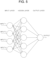
- the FC layer for monitoring the blind spots includes a neural network capable of outputting a result value of whether the monitored vehicle is located on one of the blind spots by a multilayer perceptron to which said pieces of cue information on the monitored vehicle are inputted.
- a testing method of a CNN for monitoring one or more blind spots of a monitoring vehicle, including steps of: (a) on condition that a learning device, (i) has instructed a detector on the monitoring vehicle to output class information for training and location information for training on a monitored vehicle included in a training image corresponding to at least one video image taken from the monitoring vehicle, (ii) has instructed a cue information extracting layer to perform one or more operations by using the class information for training and the location information for training on the monitored vehicle, to thereby output one or more pieces of cue information for training on the monitored vehicle, (iii) has instructed an FC layer for monitoring the blind spots to perform one or more neural network operations by using said pieces of cue information for training or their processed values , to thereby output a result for training of determining whether the monitored vehicle is located on one of the blind spots, and (iv) has instructed a first loss layer to generate one or more loss values for the blind spots by referring to the
- the detector is a vehicle detector based on an R-CNN (Region-based Convolutional Neural Network) including: one or more convolutional layers which generate a feature map for testing from the test image, an RPN (Region Proposal Network) which generates an ROI (Region Of Interest) for testing of the monitored vehicle from the feature map for testing, a pooling layer which generates a feature vector for testing by pooling an area, in the feature map for testing, corresponding to the ROI for testing, at least one FC layer for the vehicle detection which performs at least one fully connected operation on the feature vector for testing, to thereby generate one or more FC output values, a classification layer which outputs the class information for testing on the monitored vehicle by referring to the FC output values, and a regression layer which outputs the location information for testing on the monitored vehicle by referring to the FC output values.
- R-CNN Registered-based Convolutional Neural Network
- the testing device instructs the CNN to receive a concatenated value for testing acquired by using said pieces of cue information for testing on the monitored vehicle generated by the cue information extracting layer and the feature vector for testing generated by the pooling layer of the detector, as an input to the FC layer for monitoring the blind spots.
- the FC layer for monitoring the blind spots includes a neural network capable of outputting a result value for testing of whether the monitored vehicle is located on one of the blind spots by a multilayer perceptron to which said pieces of cue information for testing or their processed values on the monitored vehicle are inputted.
- said pieces of cue information for testing on the monitored vehicle include at least part of (i) the class information for testing on the monitored vehicle, (ii) the location information for testing on the monitored vehicle, (iii) size information for testing on the monitored vehicle corresponding to an ROI size, (iv) aspect ratio information for testing on the monitored vehicle, and (v) distance information for testing between a center of the monitored vehicle and one of outer sides of the blind spots.
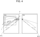
- the cue information extracting layer determines a smaller value among either of (i) a distance of one outer boundary of the blind spot BS-L from the center of the monitored vehicle and (ii) a distance of the other outer boundary of the blind spot BS-R from the center thereof as the distance information for testing between the center of the monitored vehicle and said one of the outer sides of the blind spots, and further outputs relative location information for testing in addition to the distance information for testing in order to determine whether the center of the monitored vehicle is located inside or outside of said one of the outer sides of the blind spots.
- the monitoring vehicle for the testing device is not identical to the monitoring vehicle for the learning device.
- a learning device of a CNN for monitoring one or more blind spots of a monitoring vehicle, including: a communication part for receiving a training image corresponding to at least one video image taken from the monitoring vehicle; and a processor for (I) instructing a detector on the monitoring vehicle to output class information and location information on a monitored vehicle included in the training image, (II) instructing a cue information extracting layer to perform one or more operations by using the class information and the location information on the monitored vehicle, to thereby output one or more pieces of cue information on the monitored vehicle, and instructing an FC layer for monitoring the blind spots to perform one or more neural network operations by using said pieces of cue information or their processed values on the monitored vehicle, to thereby output a result of determining whether the monitored vehicle is located on one of the blind spots of the monitoring vehicle, and (III) instructing a first loss layer to generate one or more loss values for the blind spots by referring to the result and its corresponding first GT (G)
- the detector is a vehicle detector based on an R-CNN (Region-based Convolutional Neural Network) including: one or more convolutional layers which generate a feature map from the training image, an RPN (Region Proposal Network) which generates an ROI (Region Of Interest) of the monitored vehicle from the feature map, a pooling layer which generates a feature vector by pooling an area, in the feature map, corresponding to the ROI, at least one FC layer for the vehicle detection which performs at least one fully connected operation on the feature vector, to thereby generate one or more FC output values, a classification layer which outputs the class information on the monitored vehicle by referring to the FC output values, and a regression layer which outputs the location information on the monitored vehicle by referring to the FC output values.
- R-CNN Registered-based Convolutional Neural Network
- the loss values for the vehicle detection include one or more class loss values and one or more location loss values of the monitored vehicle, wherein the processor learns one or more parameters of the FC layer for the vehicle detection and one or more parameters of the convolutional layers by backpropagating the class loss values and the location loss values.
- the processor instructs the CNN to receive a concatenated value acquired by using said pieces of cue information on the monitored vehicle generated by the cue information extracting layer and the feature vector generated by the pooling layer of the detector, as an input to the FC layer for monitoring the blind spots.
- the FC layer for monitoring the blind spots includes a neural network capable of outputting a result value of whether the monitored vehicle is located on one of the blind spots by a multilayer perceptron to which said pieces of cue information on the monitored vehicle are inputted.
- said pieces of cue information on the monitored vehicle include at least part of (i) the class information on the monitored vehicle, (ii) the location information on the monitored vehicle, (iii) size information on the monitored vehicle corresponding to an ROI (Region Of Interest) size, (iv) aspect ratio information on the monitored vehicle, and (v) distance information between a center of the monitored vehicle and one of outer sides of the blind spots.
- the cue information extracting layer determines a smaller value among either of (i) a distance of one outer boundary of the blind spot BS-L from the center of the monitored vehicle and (ii) a distance of the other outer boundary of the blind spot BS-R from the center thereof as the distance information between the center of the monitored vehicle and said one of the outer sides of the blind spots, and further outputs relative location information in addition to the distance information in order to determine whether the center of the monitored vehicle is located inside or outside of said one of the outer sides of the blind spots.
- a testing device of a CNN for monitoring one or more blind spots of a monitoring vehicle, including: a communication part for, on condition that a learning device, (i) has instructed a detector on the monitoring vehicle to output class information for training and location information for training on a monitored vehicle included in a training image corresponding to at least one video image taken from the monitoring vehicle, (ii) has instructed a cue information extracting layer to perform one or more operations by using the class information for training and the location information for training on the monitored vehicle, to thereby output one or more pieces of cue information for training on the monitored vehicle, (iii) has instructed an FC layer for monitoring the blind spots to perform one or more neural network operations by using said pieces of cue information for training or their processed values, to thereby output a result for training of determining whether the monitored vehicle is located on one of the blind spots, and (iv) has instructed a first loss layer to generate one or more loss values for the blind spots by referring
- the detector is a vehicle detector based on an R-CNN (Region-based Convolutional Neural Network) including: one or more convolutional layers which generate a feature map for testing from the test image, an RPN (Region Proposal Network) which generates an ROI (Region Of Interest) for testing of the monitored vehicle from the feature map for testing, a pooling layer which generates a feature vector for testing by pooling an area, in the feature map for testing, corresponding to the ROI for testing, at least one FC layer for the vehicle detection which performs at least one fully connected operation on the feature vector for testing, to thereby generate one or more FC output values, a classification layer which outputs the class information for testing on the monitored vehicle by referring to the FC output values, and a regression layer which outputs the location information for testing on the monitored vehicle by referring to the FC output values.
- R-CNN Registered-based Convolutional Neural Network
- said pieces of cue information for testing on the monitored vehicle include at least part of (i) the class information for testing on the monitored vehicle, (ii) the location information for testing on the monitored vehicle, (iii) size information for testing on the monitored vehicle corresponding to an ROI size, (iv) aspect ratio information for testing on the monitored vehicle, and (v) distance information for testing between a center of the monitored vehicle and one of outer sides of the blind spots.
- the cue information extracting layer determines a smaller value among either of (i) a distance of one outer boundary of the blind spot BS-L from the center of the monitored vehicle and (ii) a distance of the other outer boundary of the blind spot BS-R from the center thereof as the distance information for testing between the center of the monitored vehicle and said one of the outer sides of the blind spots, and further outputs relative location information for testing in addition to the distance information for testing in order to determine whether the center of the monitored vehicle is located inside or outside of said one of the outer sides of the blind spots.
- the monitoring vehicle for the testing device is not identical to the monitoring vehicle for the learning device.
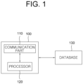
- Fig. 1 is a drawing schematically illustrating a learning device 100 for monitoring blind spots of a monitoring vehicle in accordance with one example embodiment of the present invention and, by referring to Fig. 1 , the learning device 100 may include a communication part 110 and a processor 120.
- the communication part 110 may receive training data corresponding to at least one output signal from a detector on the monitoring vehicle. That is, the communication part 110 may receive the output signal from the detector in following detailed description as an input signal, i.e., the training data.
- the training data as information on monitored vehicles in an image corresponding to an input video from the detector, may include class information on objects such as the monitored vehicles and location information on areas where the monitored vehicles are located in the image. Additionally, the training data may be stored in a database 130 where GT, i.e., ground truth, of the class information and the location information on each of the monitored vehicles corresponding to the training data may be stored.
- GT i.e., ground truth
- the detector capable of detecting the monitored vehicle in an image acquired by a vision sensor may be configured with a hypothesis generation stage of detecting an ROI (Region Of Interest), i.e., an area where the monitored vehicle is presumed to be located in the image, and a hypothesis verification stage of determining whether the detected ROI actually includes the monitored vehicle.
- the hypothesis generation stage may be implemented with a motion-based scheme using optical flows, an appearance-based scheme using shadow underneath vehicles, corners, vertical and horizontal edges, symmetry, color, vehicle's lights, stereo cameras, multiple features, or the like
- the hypothesis verification stage may be implemented with a correlation-based scheme using template matching, a learning-based scheme using features and classifiers, or the like.
- the learning-based scheme may adopt a deep learning based algorithm such as a CNN, or a shallow learning based algorithm such as a decision tree, an SVM (Support Vector Machine), an AdaBoost, k-nearest neighbors, etc.
- said pieces of cue information on the monitored vehicle may include at least part of (i) the class information on the monitored vehicle, (ii) the location information on the monitored vehicle, (iii) size information on the monitored vehicle corresponding to an ROI size, (iv) aspect ratio information on the monitored vehicle, and (v) distance information between a center of the monitored vehicle and one of outer sides of the blind spots.
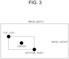
- the location information on the monitored vehicle may include information on a location corresponding to an area where the monitored vehicle is located in the image.
- coordinates of the top-left and the bottom-right corners of a bounding box in the image may be included, as information on a location of the bounding box corresponding to the monitored vehicle.
- Coordinates of a center of the bounding box which may be calculated by using the coordinates of the top-left and the bottom-right corners of the bounding box, may further be included.
- the learning device 100 may instruct the FC layer 122 for monitoring the blind spots to perform the neural network operations by using said pieces of the cue information on the monitored vehicle, to thereby output the result of determining whether the monitored vehicle is located on said one of the blind spots of the monitoring vehicle.
- the learning device 100 may instruct the loss layer 123 to generate the loss values by referring to the result from the FC layer 122 for monitoring the blind spots and its corresponding GT, to thereby learn the parameters of the FC layer 122 by backpropagating the loss values.
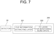
- the communication part 210 may receive class information for testing and location information for testing on a monitored vehicle from a detector 20 which detects the monitored vehicle in a test image taken from the monitoring vehicle.
- the FC layer for monitoring the blind spots has learned one or more parameters of the learning device using the learning method explained by referring to Figs. 1 to 5 , and the learning method may be briefly explained as follows.
- the learning device (i) if the training data corresponding to at least one output signal from the detector 20 on the monitoring vehicle has been inputted, has instructed the cue information extracting layer to perform the operations by using class information for training and location information for training on the monitored vehicle included in the training data, to thereby output one or more pieces of cue information for training on the monitored vehicle, (ii) has instructed the FC layer for monitoring the blind spots to perform the neural network operations by using said pieces of cue information for training on the monitored vehicle, to thereby output a result for training of determining whether the monitored vehicle is located on said one of the blind spots of the monitoring vehicle, and (iii) has instructed the loss layer to generate one or more loss values by referring to the result for training and its corresponding GT, to thereby learn the parameters of the FC layer for monitoring the blind spots by backpropagating the loss
- testing device 200 in accordance with one example embodiment of the present invention may be a computing device and may include any device having a processor capable of computation in accordance with the present invention.
- Fig. 6 represents one testing device 200 but the scope of the present invention is not limited thereto. That is, the testing device 200 may be configured as several devices to perform its functions.
- the testing device 200 may instruct the cue information extracting layer 221 to perform the operations by using the class information for testing and the location information for testing on the monitored vehicle, to thereby output said pieces of cue information for testing on the monitored vehicle.
- the distance information L for testing may include relative location information for testing, e.g., information on plus sign or negative sign, to determine whether the center of the monitored vehicle is located inside or outside of said one of outer sides of the blind spots.
- the testing device 200 may instruct the FC layer 222 for monitoring the blind spots to perform the neural network operations by using said pieces of the cue information for testing or their processed values on the monitored vehicle, to thereby output a result for testing of determining whether the monitored vehicle is located on said one of the blind spots of the monitoring vehicle.
- the processed values of said pieces of cue information for testing may represent a concatenated value acquired by using said pieces of cue information for testing on the monitored vehicle generated by the cue information extracting layer 221 and the feature vector for testing generated by the pooling layer 23 of the detector 20.
- a feature concatenation layer capable of concatenating said pieces of cue information for testing and the feature vector for testing may be located before the FC layer 222 for monitoring the blind spots.
- the FC layer 222 may include the neural network capable of outputting a result value of whether the monitored vehicle is located on said one of the blind spots by the multilayer perceptron to which said pieces of cue information for testing or their processed values on the monitored vehicle are inputted.
- the cue information extracting layer 221 and the FC layer 222 for monitoring the blind spots may be included in one computing device or in different computing devices, and may also be implemented as an algorithm performing the operations previously mentioned, in any computing devices.
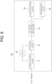
- Fig. 9 is a drawing schematically illustrating a learning device 300 for monitoring blind spots of a monitoring vehicle in accordance with another example embodiment of the present invention, and the learning device 300 may include a communication part 310 and a processor 320 by referring to Fig. 9 .
- the communication part 310 may receive a training image corresponding to at least one video image taken from the monitoring vehicle.
- the training image may be stored in a database 330 where at least one GT of class information and location information on a monitored vehicle corresponding to the training image may be stored.
- the processor 320 may perform a first process of instructing a detector 30 on the monitoring vehicle to output the class information and the location information on the monitored vehicle, a second process of instructing a cue information extracting layer to perform one or more operations by using the class information and the location information on the monitored vehicle, to thereby output one or more pieces of cue information on the monitored vehicle, and instructing an FC layer for monitoring the blind spots to perform one or more neural network operations by using said pieces of cue information or their processed values on the monitored vehicle, to thereby output a result of determining whether the monitored vehicle is located on one of the blind spots, and a third process of instructing a first loss layer to generate one or more loss values for the blind spots by referring to the result and its corresponding first GT, to thereby learn one or more parameters of the FC layer for monitoring the blind spots by backpropagating the loss values for the blind spots, and instructing a second loss layer to generate one or more loss values for vehicle detection by referring to the class information and the location information on the monitored vehicle and their corresponding second GT,
- the learning device 300 in accordance with another example embodiment of the present invention may be a computing device and may include any device having a processor capable of computation in accordance with the present invention.
- Fig. 9 represents one learning device 300 but the scope of the present invention is not limited thereto. That is, the learning device 300 may be configured as several devices to perform its functions.
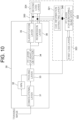
- a learning method for monitoring the blind spot of the monitoring vehicle by using the learning device configured as aforementioned in accordance with another example embodiment of the present invention may be explained as below, by referring to Fig. 10 .
- the detector 30 may output the class information and the location information on the monitored vehicle included in the training image.
- the detector 30 capable of detecting the monitored vehicle in an image acquired by a vision sensor may be configured with a hypothesis generation stage of detecting an ROI, i.e., an area where the monitored vehicle is presumed to be located in the image, and a hypothesis verification stage of determining whether the detected ROI actually includes the monitored vehicle.
- the hypothesis generation stage may be implemented with a motion-based scheme using optical flows, an appearance-based scheme using shadow underneath vehicles, corners, vertical and horizontal edges, symmetry, color, vehicle's lights, stereo cameras, multiple features, or the like
- the hypothesis verification stage may be implemented with a correlation-based scheme using template matching, a learning-based scheme using features and classifiers, or the like.
- the learning-based scheme may adopt a deep learning based algorithm, such as a CNN, or a shallow learning based algorithm, such as a decision tree, an SVM (Support Vector Machine), an AdaBoost, k-nearest neighbors, etc.
- a deep learning based algorithm such as a CNN
- a shallow learning based algorithm such as a decision tree, an SVM (Support Vector Machine), an AdaBoost, k-nearest neighbors, etc.
- the location information on the monitored vehicle may include information on a location corresponding to an area where the monitored vehicle is located in the image. For example, coordinates of the top-left and the bottom-right corners of a bounding box in the image may be included, as information on a location of the bounding box corresponding to the monitored vehicle. Coordinates of a center of the bounding box, which may be calculated by using the coordinates of the top-left and the bottom-right corners of the bounding box, may be further included.
- the distance information L may include relative location information, e.g., information on plus sign or negative sign, to determine whether the center of the monitored vehicle is located inside or outside of said one of outer sides of the blind spots.
- the learning device 300 may instruct the FC layer 322 for monitoring the blind spots to perform the neural network operations by using said pieces of the cue information or their processed values on the monitored vehicle, to thereby output the result of determining whether the monitored vehicle is located on said one of the blind spots of the monitoring vehicle.
- the processed values of said pieces of cue information may represent a concatenated value acquired by using said pieces of cue information on the monitored vehicle generated by the cue information extracting layer 321 and the feature vector generated by the pooling layer 33 of the detector 30.
- a feature concatenation layer 340 which generates the concatenated value including said pieces of cue information and the feature vector, may be located before the FC layer 322 for monitoring the blind spots.
- the FC layer 322 may include a neural network capable of outputting a result value of whether the monitored vehicle is located on said one of the blind spots by a multilayer perceptron to which said pieces of cue information or their processed values on the monitored vehicle are inputted.
- the cue information extracting layer 221 and the FC layer 222 for monitoring the blind spots may be included in one computing device or in different computing devices, and may also be implemented as an algorithm performing the operations previously mentioned, in any computing devices. Additionally, the first loss layer 323 and the second loss layer 324 may be included in one computing device or in different computing devices respectively and may be implemented as an algorithm performing the operations previously mentioned, in any computing devices.
- Fig. 11 is a drawing schematically illustrating a testing device 400 for monitoring blind spots of a monitoring vehicle, which may or may not be the same as the monitoring vehicle mentioned previously, in accordance with another example embodiment of the present invention, and the testing device 400 may include a communication part 410 and a processor 420 by referring to Fig. 11 .
- the detector 40 capable of detecting the monitored vehicle in an image acquired by a vision sensor may be configured with a hypothesis generation stage of detecting an ROI, i.e., an area where the monitored vehicle is presumed to be located in the image and a hypothesis verification stage of determining whether the detected ROI actually includes the monitored vehicle.
- the hypothesis generation stage may be implemented with a motion-based scheme using optical flows, an appearance-based scheme using shadow underneath vehicles, corners, vertical and horizontal edges, symmetry, color, vehicle's lights, stereo cameras, multiple features, or the like
- the hypothesis verification stage may be implemented with a correlation-based scheme using template matching, a learning-based scheme using features and classifiers, or the like.
- the learning-based scheme may adopt a deep learning based algorithm, such as a CNN, or a shallow learning based algorithm, such as a decision tree, an SVM (Support Vector Machine), an AdaBoost, k-nearest neighbors, etc.
- a deep learning based algorithm such as a CNN
- a shallow learning based algorithm such as a decision tree, an SVM (Support Vector Machine), an AdaBoost, k-nearest neighbors, etc.
- the detector 40 may be a vehicle detector based on the R-CNN, including the convolutional layer which generates a feature map for testing from the test image, the RPN which generates an ROI for testing of the monitored vehicle from the feature map for testing, the pooling layer which generates a feature vector for testing by pooling an area, in the feature map for testing, corresponding to the ROI for testing, the FC layer for the vehicle detection which performs the fully connected operations by using the feature vector for testing, to thereby generate one or more FC output values, the classification layer which outputs the class information for testing on the monitored vehicle by referring to the FC output values, and the regression layer which outputs the location information for testing on the monitored vehicle by referring to the FC output values.
- the convolutional layer which generates a feature map for testing from the test image
- the RPN which generates an ROI for testing of the monitored vehicle from the feature map for testing
- the pooling layer which generates a feature vector for testing by pooling an area, in the feature map for testing, corresponding to the ROI for testing
- each of the convolutional layer and the FC layer for the vehicle detection is presented as one layer, but the scope of the present invention is not limited thereto and each of them may be comprised of multiple layers.
- the feature map for testing may be outputted in form of one or more feature maps corresponding to a depth of a channel, from the convolutional layer 41.
- the processor 420 may perform a first process of instructing the cue information extracting layer to perform the operations by using the class information for testing and the location information for testing on the monitored vehicle, to thereby output one or more pieces of cue information for testing on the monitored vehicle, and a second process of instructing the FC layer for monitoring the blind spots to perform the neural network operations by using said pieces of cue information for testing or their processed values on the monitored vehicle, to thereby output a result for testing of whether the monitored vehicle is located on one of the blind spots of the monitoring vehicle.
- the detector 40 and the FC layer for monitoring the blind spots have learned the parameters of the learning device using the learning method explained by referring to Figs. 9 and 10 , and the learning method may be briefly explained as follows. If the detector 40 has outputted class information for training and location information for training on the monitored vehicle in a training image corresponding to a video image taken from the monitoring vehicle, the learning device (i) has instructed the cue information extracting layer to perform the operations by using the class information for training and the location information for training on the monitored vehicle, to thereby output one or more pieces of cue information for training on the monitored vehicle, (ii) has instructed the FC layer for monitoring the blind spots to perform the neural network operations by using said pieces of cue information for training or their processed values, to thereby output a result for training of whether the monitored vehicle is located on said one of the blind spots, and (iii) has instructed the first loss layer to generate one or more loss values for the blind spots by referring to the result for training and its corresponding first GT, to thereby learn the parameters of the FC layer for monitoring
- testing device 400 in accordance with another example embodiment of the present invention may be a computing device and may include any device having a processor capable of computation in accordance with the present invention.
- Fig. 11 represents one testing device 400 but the scope of the present invention is not limited thereto. That is, the testing device 400 may be configured as several devices to perform its functions.
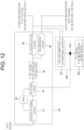
- a testing method for monitoring the blind spots using the testing device for monitoring the blind spots configured as aforementioned in accordance with another example embodiment of the present invention may be explained as below, by referring to Fig. 12 .
- the learning device (i) has instructed the cue information extracting layer 421 to perform the operations by using the class information for training and location information for training on the monitored vehicle, to thereby output said pieces of cue information for training on the monitored vehicle, (ii) has instructed the FC layer 422 for monitoring the blind spots to perform the neural network operations by using said pieces of cue information for training or their processed values, to thereby output the result for training of whether the monitored vehicle is located on said one of the blind spots, and (iii) has instructed the first loss layer to generate the loss values for the blind spots by referring to the result for training and its corresponding first GT, to thereby learn the parameters of the FC layer 422 for monitoring the blind spots by backpropagating the loss values for the blind spots, and has instructed the second loss layer to generate the loss values for the vehicle detection by referring to the class information for training and the location
- the detector 40 capable of detecting the monitored vehicle in an image acquired by the vision sensor may be configured with the hypothesis generation stage of detecting the ROI, i.e., the area where the monitored vehicle is presumed to be located in the image, and the hypothesis verification stage of determining whether the detected ROI actually includes the monitored vehicle.
- the hypothesis generation stage may be implemented with a motion-based scheme using optical flows, an appearance-based scheme using shadow underneath vehicle, corners, vertical and horizontal edges, symmetry, color, vehicle's lights, stereo cameras, multiple features, or the like
- the hypothesis verification stage may be implemented with a correlation-based scheme using template matching, a learning-based scheme using features and classifiers, or the like.
- the learning-based scheme may adopt a deep learning based algorithm, such as a CNN, or a shallow learning based algorithm, such as a decision tree, an SVM (Support Vector Machine), an AdaBoost, k-nearest neighbors, etc.
- a deep learning based algorithm such as a CNN
- a shallow learning based algorithm such as a decision tree, an SVM (Support Vector Machine), an AdaBoost, k-nearest neighbors, etc.
- the testing device 400 may instruct the cue information extracting layer 421 to perform the operations by using the class information for testing and the location information for testing on the monitored vehicle, to thereby output said pieces of cue information for testing on the monitored vehicle.
- the class information for testing on the monitored vehicle may include class information for classifying the monitored vehicle as a car, a motorcycle, etc.
- the location information for testing on the monitored vehicle may include information on a location corresponding to an area where the monitored vehicle is located in the test image. For example, coordinates of the top-left and the bottom-right corners of a bounding box in the test image may be included, as information on a location of the bounding box corresponding to the monitored vehicle. Coordinates of a center of the bounding box, which may be calculated by using the coordinates of the top-left and the bottom-right corners of the bounding box, may be further included.
- the distance information L for testing may include relative location information for testing, e.g., information on plus sign or negative sign, to determine whether the center of the monitored vehicle is located inside or outside of said one of outer sides of the blind spots.
- the testing device 400 may instruct the FC layer 422 for monitoring the blind spots to perform the neural network operations by using said pieces of the cue information for testing or their processed values on the monitored vehicle, to thereby output the result for testing of determining whether the monitored vehicle is located on said one of the blind spots of the monitoring vehicle.
- the processed values of said pieces of cue information for testing may represent a concatenated value acquired by using said pieces of cue information for testing on the monitored vehicle generated by the cue information extracting layer 421 and the feature vector for testing generated by the pooling layer 43 of the detector 40.
- a feature concatenation layer 440 which generates the concatenated value including said pieces of cue information for testing and the feature vector for testing, may be located before the FC layer 422 for monitoring the blind spots.
- the FC layer 422 for monitoring the blind spots may include the neural network capable of outputting a result value of whether the monitored vehicle is located on said one of the blind spots by the multilayer perceptron to which said pieces of cue information for testing or their processed values on the monitored vehicle are inputted.
- the cue information extracting layer 421 and the FC layer 422 for monitoring the blind spots may be included in one computing device or in different computing devices, and also may be implemented as an algorithm performing the operations previously mentioned, in any computing devices.
- the present invention has an effect of providing a blind spot monitoring system regardless of the type of a detector which detects a vehicle.
- the present invention has another effect of determining whether the vehicle is located on blind spots by using an output signal from the detector, regardless of the type of the detector.
- the present invention has still another effect of minimizing cost of maintaining the blind spot monitoring system since the detector in the blind spot monitoring system is replaceable as needed without designing a logic.
- the present invention has still yet another effect of no need to design the logic corresponding to each detector for determining whether the vehicle is located on the blind spot, thereby minimizing time required to develop the blind spot monitoring system, as the blind spot monitoring system is adaptable to all detectors.
- Program commands include not only a machine language code made by a compiler but also a high level language code that can be executed by a computer using an interpreter, etc.
- the hardware device can work as more than a software module to perform the process in accordance with the present invention and they can do the same in the opposite case.
Landscapes
- Engineering & Computer Science (AREA)
- Theoretical Computer Science (AREA)
- Physics & Mathematics (AREA)
- General Physics & Mathematics (AREA)
- Evolutionary Computation (AREA)
- Artificial Intelligence (AREA)
- Health & Medical Sciences (AREA)
- General Health & Medical Sciences (AREA)
- Multimedia (AREA)
- Software Systems (AREA)
- Computing Systems (AREA)
- Life Sciences & Earth Sciences (AREA)
- Computer Vision & Pattern Recognition (AREA)
- Data Mining & Analysis (AREA)
- Molecular Biology (AREA)
- Biomedical Technology (AREA)
- Mathematical Physics (AREA)
- General Engineering & Computer Science (AREA)
- Computational Linguistics (AREA)
- Biophysics (AREA)
- Databases & Information Systems (AREA)
- Medical Informatics (AREA)
- Biodiversity & Conservation Biology (AREA)
- Automation & Control Theory (AREA)
- Transportation (AREA)
- Mechanical Engineering (AREA)
- Bioinformatics & Cheminformatics (AREA)
- Bioinformatics & Computational Biology (AREA)
- Evolutionary Biology (AREA)
- Image Analysis (AREA)
- Traffic Control Systems (AREA)
- Information Retrieval, Db Structures And Fs Structures Therefor (AREA)
Claims (13)
- Lernverfahren eines neuronalen Faltungsnetzwerkes, CNN, zum Überwachen eines oder mehrerer toter Winkel eines Überwachungsfahrzeugs, umfassend die folgenden Schritte:(a) dass eine Lernvorrichtung (100), wenn ein Trainingsbild, das mindestens einem von dem Überwachungsfahrzeug genommenen Videobild entspricht, eingegeben wird, einen Detektor (30) an dem Überwachungsfahrzeug anweist, Klasseninformationen und Standortinformationen zu einem überwachten Fahrzeug, das in dem Trainingsbild beinhaltet ist, auszugeben, wobei die Klasseninformationen und die Standortinformationen Ergebnisse von Detektieren des überwachten Fahrzeugs in dem Trainingsbild durch den Detektor sind, wobei die Klasseninformationen eine Klasse eines Objektes in Bezug auf das überwachte Fahrzeug sind und wobei das Standortbild ein Standort ist, der einem Bereich entspricht, in dem sich das überwachte Fahrzeug in dem Trainingsbild befindet, einschließlich einer oder mehrerer Koordinaten eines Begrenzungsrahmens in dem Trainingsbild;(b) dass die Lernvorrichtung (100) eine Schlüsselinformationen extrahierende Schicht (121; 321) dazu anweist, einen oder mehrere Vorgänge unter Verwendung der Klasseninformationen und der Standortinformationen zu dem überwachten Fahrzeug durchzuführen, um dadurch eine oder mehrere einzelne Schlüsselinformationen zu dem überwachten Fahrzeug auszugeben, wobei die einzelnen Schlüsselinformationen zu dem überwachten Fahrzeug mindestens einen Teil (i) der Klasseninformationen zu dem überwachten Fahrzeug, (ii) der Standortinformationen zu dem überwachten Fahrzeug, einschließlich zusätzlicher Koordinaten des Begrenzungsrahmens, die der einen oder den mehreren Koordinaten des Begrenzungsrahmens entsprechen, (iii) von Größeninformationen zu dem überwachten Fahrzeug, die der Größe einer Region von Interesse, ROI, entsprechen, (iv) von Aspektverhältnisinformationen zu dem überwachten Fahrzeug und (v) von Abstandsinformationen zwischen einer Mitte des überwachten Fahrzeugs und einer von Außenseiten der toten Winkel beinhalten, und dass die Lernvorrichtung eine vollständig verbundene Schicht, FC-Schicht, zum Überwachen der toten Winkel (122; 322) dazu anweist, einen oder mehrere Vorgänge des neuralen Netzwerkes unter Verwendung der einzelnen Schlüsselinformationen oder ihrer verarbeiteten Werte zu dem überwachten Fahrzeug durchzuführen, um dadurch ein Ergebnis von Bestimmen, ob sich das überwachte Fahrzeug in einem der toten Winkel des Überwachungsfahrzeugs befindet, auszugeben; und(c) dass die Lernvorrichtung (100) eine erste Verlustschicht (123; 323) dazu anweist, einen oder mehrere Verlustwerte für die toten Winkel unter Bezugnahme auf das Ergebnis und seine entsprechende erste Ground Truth, GT, zu generieren, um dadurch einen oder mehrere Parameter der FC-Schicht zum Überwachen der toten Winkel (122; 322) durch Rückpropagieren der Verlustwerte für die toten Winkel zu lernen, und eine zweite Verlustschicht (324) dazu anweist, einen oder mehrere Verlustwerte zur Fahrzeugdetektion unter Bezugnahme auf die Klasseninformationen und die Standortinformationen zu dem überwachten Fahrzeug und ihre entsprechende zweite GT zu generieren, um dadurch einen oder mehrere Parameter des Detektors (30) durch Rückpropagieren der Verlustwerte für die Fahrzeugdetektion zu lernen.
- Lernverfahren nach Anspruch 1, wobei der Detektor (30) ein Fahrzeugdetektor ist, der auf einem regionenbasierten neuronalen Faltungsnetzwerk, R-CNN, basiert, beinhaltend:eine oder mehrere Faltungsschichten, die eine Merkmalskarte anhand des Trainingsbildes generieren,ein Regionenvorschlagsnetzwerk, RPN, das eine Region von Interesse, ROI, des überwachten Fahrzeugs anhand der Merkmalskarte generiert,eine Bündelungsschicht (33), die einen Merkmalsvektor durch Bündeln eines Bereiches in der Merkmalskarte generiert, welcher der ROI entspricht,mindestens eine vollständig verbundene Schicht, FC-Schicht, für die Fahrzeugdetektion (34), die mindestens einen vollständig verbundenen Vorgang an dem Merkmalsvektor durchführt, um dadurch einen oder mehrere FC-Ausgabewerte zu generieren,eine Klassifizierungsschicht (35), welche die Klasseninformationen zu dem überwachten Fahrzeug unter Bezugnahme auf die FC-Ausgabewerte ausgibt, undeine Regressionsschicht (36), welche die Standortinformationen zu dem überwachten Fahrzeug unter Bezugnahme auf die FC-Ausgabewerte ausgibt.
- Lernverfahren nach Anspruch 2, wobei die Verlustwerte für die Fahrzeugdetektion einen oder mehrere Klassenverlustwerte und einen oder mehrere Standortverlustwerte des überwachten Fahrzeugs beinhalten und
wobei die Lernvorrichtung einen oder mehrere Parameter der FC-Schicht für die Fahrzeugdetektion (34) und einen oder mehrere Parameter der Faltungsschichten (31) durch Rückpropagieren der Klassenverlustwerte und der Standortverlustwerte lernt. - Lernverfahren nach Anspruch 2, wobei die Lernvorrichtung das CNN dazu anweist, einen verketteten Wert zu empfangen, der unter Verwendung der einzelnen Schlüsselinformationen zu dem überwachten Fahrzeug, die durch die Schlüsselinformationen extrahierende Schicht (321) generiert werden, und des Merkmalsvektors, der durch die Bündelungsschicht (33) des Detektors generiert wird, als Eingabe in die FC-Schicht zum Überwachen der toten Winkel (322) erfasst wird.
- Lernverfahren nach Anspruch 1, wobei die FC-Schicht zum Überwachen der toten Winkel (322) ein neuronales Netzwerk beinhaltet, das in der Lage ist, einen Ergebniswert davon, ob sich das überwachte Fahrzeug in einem der toten Winkel befindet, durch einen mehrschichtigen Perzeptron, in den die einzelnen Schlüsselinformationen zu dem überwachten Fahrzeug eingegeben werden, auszugeben.
- Lernverfahren nach Anspruch 1, wobei die Schlüsselinformationen extrahierende Schicht (321) einen kleineren Wert unter einem von (i) einem Abstand einer Außengrenze des toten Winkels, BS-L, von der Mitte des überwachten Fahrzeugs und (ii) einem Abstand der anderen Außengrenze des toten Winkels, BS-R, von der Mitte davon als die Abstandsinformationen zwischen der Mitte des überwachten Fahrzeugs und der einen der Außenseiten der toten Winkel bestimmt und ferner relative Standortinformationen zusätzlich zu den Abstandsinformationen ausgibt, um zu bestimmen, ob sich die Mitte des überwachten Fahrzeugs innerhalb oder außerhalb der einen der Außenseiten der toten Winkel befindet.
- Prüfverfahren eines neuronalen Faltungsnetzwerkes, CNN, zum Überwachen eines oder mehrerer toter Winkel eines Überwachungsfahrzeugs, die mit dem Verfahren nach Anspruch 1 erlangt werden, umfassend die folgenden Schritte:(a) dass eine Prüfvorrichtung einen Detektor an dem Überwachungsfahrzeug dazu anweist, zu prüfende Klasseninformationen und zu prüfende Standortinformationen zu einem überwachten Fahrzeug, das in einem von dem Überwachungsfahrzeug genommenen Prüfbild beinhaltet ist, auszugeben; und(b) dass die Prüfvorrichtung die Schlüsselinformationen extrahierende Schicht (421) dazu anweist, die Vorgänge unter Verwendung der zu prüfenden Klasseninformationen und der zu prüfenden Standortinformationen zu dem überwachten Fahrzeug durchzuführen, um dadurch eine oder mehrere einzelne zu prüfende Schlüsselinformationen zu dem überwachten Fahrzeug auszugeben, wobei die einzelnen Schlüsselinformationen zu dem überwachten Fahrzeug mindestens einen Teil (i) der Klasseninformationen zu dem überwachten Fahrzeug, (ii) der Standortinformationen zu dem überwachten Fahrzeug, (iii) von Größeninformationen zu dem überwachten Fahrzeug, die der Größe von n Regionen von Interesse, ROI, entsprechen, (iv) von Aspektverhältnisinformationen zu dem überwachten Fahrzeug und (v) von Abstandsinformationen zwischen einer Mitte des überwachten Fahrzeugs und einer von Außenseiten der toten Winkel beinhalten, und dass die Prüfvorrichtung die FC-Schicht zum Überwachen der toten Winkel (422) dazu anweist, die Vorgänge des neuronalen Netzwerkes unter Verwendung der einzelnen zu prüfenden Schlüsselinformationen oder ihrer verarbeiteten Werte zu dem überwachten Fahrzeug durchzuführen, um dadurch ein zu prüfendes Ergebnis von Bestimmen, ob sich das überwachte Fahrzeug in einem der toten Winkel des Überwachungsfahrzeugs befindet, auszugeben.
- Lernvorrichtung (100) eines neuronalen Faltungsnetzwerkes, CNN, zum Überwachen eines oder mehrerer toter Winkel eines Überwachungsfahrzeugs, umfassend:ein Kommunikationsteil (110) zum Empfangen eines Trainingsbildes, das mindestens einem von dem Überwachungsfahrzeug genommenen Videobild entspricht; undeinen Prozessor (120), der zu Folgendem konfiguriert ist:(I) Anweisen eines Detektors (30) an dem Überwachungsfahrzeug dazu, Klasseninformationen und Standortinformationen zu einem überwachten Fahrzeug, das in dem Trainingsbild beinhaltet ist, auszugeben, wobei die Klasseninformationen und die Standortinformationen Ergebnisse von Detektieren des überwachen Fahrzeugs in dem Trainingsbild durch den Detektor sind, wobei die Klasseninformationen eine Klasse eines Objektes in Bezug auf das überwachte Fahrzeug sind und wobei das Standortbild ein Standort ist, der einem Bereich entspricht, in dem sich das überwachte Fahrzeug in dem Trainingsbild befindet, einschließlich einer oder mehrerer Koordinaten eines Begrenzungsrahmens in dem Trainingsbild,(II) Anweisen einer Schlüsselinformationen extrahierenden Schicht (321) dazu, einen oder mehrere Vorgänge unter Verwendung der Klasseninformationen und der Standortinformationen zu dem überwachten Fahrzeug durchzuführen, um dadurch eine oder mehrere einzelne Schlüsselinformationen zu dem überwachen Fahrzeug auszugeben, wobei die einzelnen Schlüsselinformationen zu dem überwachten Fahrzeug mindestens einen Teil (i) der Klasseninformationen zu dem überwachten Fahrzeug, (ii) der Standortinformationen zu dem überwachten Fahrzeug, einschließlich zusätzlicher Koordinaten des Begrenzungsrahmens, die der einen oder den mehreren Koordinaten des Begrenzungsrahmens entsprechen, (iii) von Größeninformationen zu dem überwachten Fahrzeug, die der Größe von n Regionen von Interesse, ROI, entsprechen, (iv) von Aspektverhältnisinformationen zu dem überwachten Fahrzeug und (v) von Abstandsinformationen zwischen einer Mitte des überwachten Fahrzeugs und einer von Außenseiten der toten Winkel beinhalten, wobei der Prozessor ferner dazu konfiguriert ist, eine vollständig verbundene Schicht, FC-Schicht, zum Überwachen der toten Winkel (322) dazu anzuweisen, einen oder mehrere Vorgänge des neuronalen Netzwerkes unter Verwendung der einzelnen Schlüsselinformationen oder ihrer verarbeiteten Werte zu dem überwachten Fahrzeug durchzuführen, um dadurch ein Ergebnis von Bestimmen, ob sich das überwachte Fahrzeug in einem der toten Winkel des Überwachungsfahrzeugs befindet, auszugeben, und(III) Anweisen einer ersten Verlustschicht (322) dazu, einen oder mehrere Verlustwerte für die toten Winkel unter Bezugnahme auf das Ergebnis und seiner entsprechende erste Ground Truth, GT, zu generieren, um dadurch einen oder mehrere Parameter der FC-Schicht zum Überwachen der toten Winkel (322) durch Rückpropagieren der Verlustwerte für die toten Winkel zu lernen, und Anweisen einer zweiten Verlustschicht (324) dazu, einen oder mehrere Verlustwerte zur Fahrzeugdetektion unter Bezugnahme auf die Klasseninformationen und die Standortinformationen zu dem überwachten Fahrzeug und ihre entsprechende zweite GT zu generieren, um dadurch einen oder mehrere Parameter des Detektors durch Rückpropagieren der Verlustwerte für die Fahrzeugdetektion zu lernen.
- Lernvorrichtung nach Anspruch 8, wobei der Detektor ein Fahrzeugdetektor ist, der auf einem regionenbasierten neuronalen Faltungsnetzwerk, R-CNN, basiert, beinhaltend:eine oder mehrere Faltungsschichten (31), die eine Merkmalskarte anhand des Trainingsbildes generieren,ein Regionenvorschlagsnetzwerk, RPN, das eine Region von Interesse, ROI, des überwachten Fahrzeugs anhand der Merkmalskarte generiert,eine Bündelungsschicht (33), die einen Merkmalsvektor durch Bündeln eines Bereiches in der Merkmalskarte generiert, welcher der ROI entspricht,mindestens eine vollständig verbundene Schicht, FC-Schicht, für die Fahrzeugdetektion (34), die mindestens einen vollständig verbundenen Vorgang an dem Merkmalsvektor ausführt, um dadurch einen oder mehrere FC-Ausgabewerte zu generieren,eine Klassifizierungsschicht (35), welche die Klasseninformationen zu dem überwachten Fahrzeug unter Bezugnahme auf die FC-Ausgabewerte ausgibt, undeine Regressionsschicht (36), welche die Standortinformationen zu dem überwachten Fahrzeug unter Bezugnahme auf die FC-Ausgabewerte ausgibt.
- Lernvorrichtung nach Anspruch 9, wobei die Verlustwerte für die Fahrzeugdetektion einen oder mehrere Klassenverlustwerte und einen oder mehrere Standortverlustwerte des überwachten Fahrzeugs beinhalten,wobei der Prozessor einen oder mehrere Parameter der FC-Schicht für die Fahrzeugdetektion (34) und einen oder mehrere Parameter der Faltungsschichten (31) durch Rückpropagieren der Klassenverlustwerte und der Standortverlustwerte lernt undwobei der Prozessor das CNN dazu anweist, einen verketteten Wert zu empfangen, der unter Verwendung der einzelnen Schlüsselinformationen zu dem überwachten Fahrzeug, die durch die Schlüsselinformationen extrahierende Schicht (321) generiert werden, und des Merkmalsvektors, der durch die Bündelungsschicht (33) des Detektors generiert wird, als Eingabe in die FC-Schicht zum Überwachen der toten Winkel (322) erfasst wird.
- Lernvorrichtung nach Anspruch 8, wobei die FC-Schicht zum Überwachen der toten Winkel (322) ein neuronales Netzwerk beinhaltet, das in der Lage ist, einen Ergebniswert davon, ob sich das überwachte Fahrzeug in einem der toten Winkel befindet, durch einen mehrschichtigen Perzeptron, in den die einzelnen Schlüsselinformationen zu dem überwachten Fahrzeug eingegeben werden, auszugeben.
- Lernvorrichtung nach Anspruch 8, wobei die Schlüsselinformationen extrahierende Schicht einen kleineren Wert unter einem von (i) einem Abstand einer Außengrenze des toten Winkels, BS-L, von der Mitte des überwachten Fahrzeugs und (ii) einem Abstand der anderen Außengrenze des toten Winkels, BS-R, von der Mitte davon als die Abstandsinformationen zwischen der Mitte des überwachten Fahrzeugs und der einen der Außenseiten der toten Winkel bestimmt und ferner relative Standortinformationen zusätzlich zu den Abstandsinformationen ausgibt, um zu bestimmen, ob sich die Mitte des überwachten Fahrzeugs innerhalb oder außerhalb der einen der Außenseiten der toten Winkel befindet.
- Prüfvorrichtung eines neuronalen Faltungsnetzwerkes, CNN, zum Überwachen eines oder mehrerer toter Winkel eines Überwachungsfahrzeugs, die mit der Lernvorrichtung nach Anspruch 8 erlangt werden, umfassend:ein Kommunikationsteil zum Erfassen von zu prüfenden Klasseninformationen und zu prüfenden Standortinformationen zu dem überwachten Fahrzeug von dem Detektor, der das überwachte Fahrzeug in einem von dem Überwachungsfahrzeug genommenen Prüfbild detektiert; undeinen Prozessor, der zu Folgendem konfiguriert ist:(I) Anweisen der Schlüsselinformationen extrahierenden Schicht dazu, die Vorgänge unter Verwendung der zu prüfenden Klasseninformationen und der zu prüfenden Standortinformationen zu dem überwachten Fahrzeug durchzuführen, um dadurch eine oder mehrere einzelne zu prüfende Schlüsselinformationen zu dem überwachen Fahrzeug auszugeben, wobei die einzelnen Schlüsselinformationen zu dem überwachten Fahrzeug mindestens einen Teil (i) der Klasseninformationen zu dem überwachten Fahrzeug, (ii) der Standortinformationen zu dem überwachten Fahrzeug, (iii) von Größeninformationen zu dem überwachten Fahrzeug, die der Größe von n Regionen von Interesse, ROI, entsprechen, (iv) von Aspektverhältnisinformationen zu dem überwachten Fahrzeug und (v) von Abstandsinformationen zwischen einer Mitte des überwachten Fahrzeugs und einer von Außenseiten der toten Winkel beinhalten, und(II) Anweisen der FC-Schicht zum Überwachen der toten Winkel dazu, die Vorgänge des neuronalen Netzwerkes unter Verwendung der einzelnen zu prüfenden Schlüsselinformationen oder ihrer verarbeiteten Werte zu dem überwachten Fahrzeug durchzuführen, um dadurch ein zu prüfendes Ergebnis von Bestimmen, ob sich das überwachte Fahrzeug in einem der toten Winkel des Überwachungsfahrzeugs befindet, auszugeben.
Applications Claiming Priority (1)
| Application Number | Priority Date | Filing Date | Title |
|---|---|---|---|
| US16/152,699 US10474930B1 (en) | 2018-10-05 | 2018-10-05 | Learning method and testing method for monitoring blind spot of vehicle, and learning device and testing device using the same |
Publications (3)
| Publication Number | Publication Date |
|---|---|
| EP3633558A1 EP3633558A1 (de) | 2020-04-08 |
| EP3633558C0 EP3633558C0 (de) | 2025-07-02 |
| EP3633558B1 true EP3633558B1 (de) | 2025-07-02 |
Family
ID=67874282
Family Applications (1)
| Application Number | Title | Priority Date | Filing Date |
|---|---|---|---|
| EP19195517.8A Active EP3633558B1 (de) | 2018-10-05 | 2019-09-05 | Lernverfahren und prüfverfahren zum überwachen des toten winkels eines fahrzeugs und lernvorrichtung und prüfvorrichtung damit |
Country Status (5)
| Country | Link |
|---|---|
| US (1) | US10474930B1 (de) |
| EP (1) | EP3633558B1 (de) |
| JP (1) | JP6814334B2 (de) |
| KR (1) | KR102349953B1 (de) |
| CN (1) | CN111008553B (de) |
Families Citing this family (6)
| Publication number | Priority date | Publication date | Assignee | Title |
|---|---|---|---|---|
| US10853698B2 (en) * | 2016-11-09 | 2020-12-01 | Konica Minolta Laboratory U.S.A., Inc. | System and method of using multi-frame image features for object detection |
| US10726303B1 (en) * | 2019-01-30 | 2020-07-28 | StradVision, Inc. | Learning method and learning device for switching modes of autonomous vehicle based on on-device standalone prediction to thereby achieve safety of autonomous driving, and testing method and testing device using the same |
| US10817777B2 (en) * | 2019-01-31 | 2020-10-27 | StradVision, Inc. | Learning method and learning device for integrating object detection information acquired through V2V communication from other autonomous vehicle with object detection information generated by present autonomous vehicle, and testing method and testing device using the same |
| CN111652128B (zh) * | 2020-06-02 | 2023-09-01 | 浙江大华技术股份有限公司 | 一种高空电力作业安全监测方法、系统和存储装置 |
| CN113239912B (zh) * | 2021-07-13 | 2021-09-17 | 天津所托瑞安汽车科技有限公司 | Bsd图像有效区域的确定方法、设备和存储介质 |
| KR102496765B1 (ko) | 2022-10-11 | 2023-02-07 | 유희경 | 자동차용 블라인드 |
Family Cites Families (31)
| Publication number | Priority date | Publication date | Assignee | Title |
|---|---|---|---|---|
| JPH10181603A (ja) * | 1996-12-25 | 1998-07-07 | Toshiba Corp | 乗車列車選択支援情報作成装置 |
| ES2158827B1 (es) * | 2000-02-18 | 2002-03-16 | Fico Mirrors Sa | Dispositivo de deteccion de presencia de objetos. |
| JP4552305B2 (ja) * | 2000-10-02 | 2010-09-29 | 日産自動車株式会社 | 画像表示装置および表示方法 |
| ES2177469B1 (es) * | 2001-05-16 | 2003-12-16 | Fico Mirrors Sa | Dispositivo de deteccion de presencia de objetos en un angulo muerto de un vehiculo automovil. |
| US6859148B2 (en) * | 2002-10-30 | 2005-02-22 | Ford Global Technologies, Llc | Blind spot warning system for an automotive vehicle |
| GB0605069D0 (en) * | 2006-03-14 | 2006-04-26 | Airmax Group Plc | Method and system for driver style monitoring and analysing |
| US8050863B2 (en) * | 2006-03-16 | 2011-11-01 | Gray & Company, Inc. | Navigation and control system for autonomous vehicles |
| JP5620147B2 (ja) * | 2010-05-24 | 2014-11-05 | 株式会社豊田中央研究所 | 可動物予測装置及びプログラム |
| US10099614B2 (en) * | 2011-11-28 | 2018-10-16 | Magna Electronics Inc. | Vision system for vehicle |
| US9069080B2 (en) * | 2013-05-24 | 2015-06-30 | Advanced Scientific Concepts, Inc. | Automotive auxiliary ladar sensor |
| JP2016006626A (ja) * | 2014-05-28 | 2016-01-14 | 株式会社デンソーアイティーラボラトリ | 検知装置、検知プログラム、検知方法、車両、パラメータ算出装置、パラメータ算出プログラムおよびパラメータ算出方法 |
| KR101692628B1 (ko) * | 2014-12-24 | 2017-01-04 | 한동대학교 산학협력단 | 관심영역을 이용하여 차량의 후방 좌우 옆 차선 영역을 감지하는 방법 및 이를 이용한 차량용 영상 모니터링 시스템 |
| US10395764B2 (en) * | 2015-01-06 | 2019-08-27 | Aic Innovations Group, Inc. | Method and apparatus for recognition of patient activity |
| US9840003B2 (en) * | 2015-06-24 | 2017-12-12 | Brain Corporation | Apparatus and methods for safe navigation of robotic devices |
| US11144834B2 (en) * | 2015-10-09 | 2021-10-12 | Fair Isaac Corporation | Method for real-time enhancement of a predictive algorithm by a novel measurement of concept drift using algorithmically-generated features |
| US20170124409A1 (en) * | 2015-11-04 | 2017-05-04 | Nec Laboratories America, Inc. | Cascaded neural network with scale dependent pooling for object detection |
| US10002313B2 (en) * | 2015-12-15 | 2018-06-19 | Sighthound, Inc. | Deeply learned convolutional neural networks (CNNS) for object localization and classification |
| US9805274B2 (en) * | 2016-02-03 | 2017-10-31 | Honda Motor Co., Ltd. | Partially occluded object detection using context and depth ordering |
| JP2017162438A (ja) * | 2016-03-11 | 2017-09-14 | パナソニック インテレクチュアル プロパティ コーポレーション オブ アメリカPanasonic Intellectual Property Corporation of America | 危険予測方法 |
| US10055652B2 (en) * | 2016-03-21 | 2018-08-21 | Ford Global Technologies, Llc | Pedestrian detection and motion prediction with rear-facing camera |
| US10115025B2 (en) * | 2016-06-13 | 2018-10-30 | Ford Global Technologies, Llc | Detecting visibility of a vehicle to driver of other vehicles |
| US20170355263A1 (en) * | 2016-06-13 | 2017-12-14 | Ford Global Technologies, Llc | Blind Spot Detection Systems And Methods |
| CN106407931B (zh) * | 2016-09-19 | 2019-11-22 | 杭州电子科技大学 | 一种深度卷积神经网络运动车辆检测方法 |
| CN106599939A (zh) * | 2016-12-30 | 2017-04-26 | 深圳市唯特视科技有限公司 | 一种基于区域卷积神经网络的实时目标检测方法 |
| JP6719399B2 (ja) * | 2017-02-10 | 2020-07-08 | ヤフー株式会社 | 解析装置、解析方法、およびプログラム |
| JP6823495B2 (ja) * | 2017-02-27 | 2021-02-03 | 株式会社日立製作所 | 情報処理装置および画像認識装置 |
| US11308391B2 (en) * | 2017-03-06 | 2022-04-19 | Baidu Usa Llc | Offline combination of convolutional/deconvolutional and batch-norm layers of convolutional neural network models for autonomous driving vehicles |
| US9934440B1 (en) * | 2017-10-04 | 2018-04-03 | StradVision, Inc. | Method for monitoring blind spot of monitoring vehicle and blind spot monitor using the same |
| US9947228B1 (en) * | 2017-10-05 | 2018-04-17 | StradVision, Inc. | Method for monitoring blind spot of vehicle and blind spot monitor using the same |
| US10083375B1 (en) * | 2017-10-13 | 2018-09-25 | StradVision, Inc. | Method and device for performing activation and convolution operation at the same time and learning method and learning device for the same |
| US10836379B2 (en) * | 2018-03-23 | 2020-11-17 | Sf Motors, Inc. | Multi-network-based path generation for vehicle parking |
-
2018
- 2018-10-05 US US16/152,699 patent/US10474930B1/en active Active
-
2019
- 2019-08-27 KR KR1020190105496A patent/KR102349953B1/ko active Active
- 2019-09-05 EP EP19195517.8A patent/EP3633558B1/de active Active
- 2019-10-02 JP JP2019182005A patent/JP6814334B2/ja active Active
- 2019-10-08 CN CN201910949146.3A patent/CN111008553B/zh active Active
Also Published As
| Publication number | Publication date |
|---|---|
| EP3633558C0 (de) | 2025-07-02 |
| KR20200039548A (ko) | 2020-04-16 |
| JP6814334B2 (ja) | 2021-01-20 |
| US10474930B1 (en) | 2019-11-12 |
| EP3633558A1 (de) | 2020-04-08 |
| JP2020061140A (ja) | 2020-04-16 |
| KR102349953B1 (ko) | 2022-01-12 |
| CN111008553A (zh) | 2020-04-14 |
| CN111008553B (zh) | 2023-11-28 |
Similar Documents
| Publication | Publication Date | Title |
|---|---|---|
| EP3633558B1 (de) | Lernverfahren und prüfverfahren zum überwachen des toten winkels eines fahrzeugs und lernvorrichtung und prüfvorrichtung damit | |
| US10643085B1 (en) | Method and device for estimating height and weight of passengers using body part length and face information based on human's status recognition | |
| US9934440B1 (en) | Method for monitoring blind spot of monitoring vehicle and blind spot monitor using the same | |
| US10635917B1 (en) | Method and device for detecting vehicle occupancy using passenger's keypoint detected through image analysis for humans' status recognition | |
| US9947228B1 (en) | Method for monitoring blind spot of vehicle and blind spot monitor using the same | |
| US10878288B2 (en) | Database construction system for machine-learning | |
| JP6888950B2 (ja) | 画像処理装置、外界認識装置 | |
| JP7135665B2 (ja) | 車両制御システム、車両の制御方法及びコンピュータプログラム | |
| EP3637309B1 (de) | Lernverfahren und prüfverfahren zur überwachung des toten winkels eines fahrzeugs sowie lernvorrichtung und prüfvorrichtung damit | |
| EP3690716A1 (de) | Verfahren und vorrichtung zum zusammenführen von objektdetektionsinformationen, die von jedem der objektdetektoren erfasst werden, die jeder kamera in der nähe entsprechen, zum zwecke des kollaborativen fahrens unter verwendung von v2x-fähigen anwendungen, sensorfusion über mehrere fahrzeuge | |
| AU2021301647B2 (en) | Obstacle detector and obstacle detection method | |
| KR20210042579A (ko) | 주행 중인 차량 내 승차인원 검지를 위한 승차위치 확인 및 합산 방법 | |
| US11106214B2 (en) | Artificial neural network-based projection information recognition apparatus and method thereof | |
| KR102239734B1 (ko) | 어라운드 뷰 모니터링 시스템을 이용한 자율 주행 차량을 위한 이동 경로 생성 장치 및 방법 | |
| Liu | Development of a vision-based object detection and recognition system for intelligent vehicle | |
| JP7379268B2 (ja) | 画像処理装置 | |
| US12515605B2 (en) | Vehicle cabin-based target detection and tracking | |
| KR102039814B1 (ko) | 측후방 차량 검출 방법 및 그 장치 | |
| US20240001933A1 (en) | Occupant temperature estimating device, occupant state detection device, occupant temperature estimating method, and occupant temperature estimating system | |
| KR101292115B1 (ko) | 차량용 영상 시스템 |
Legal Events
| Date | Code | Title | Description |
|---|---|---|---|
| PUAI | Public reference made under article 153(3) epc to a published international application that has entered the european phase |
Free format text: ORIGINAL CODE: 0009012 |
|
| STAA | Information on the status of an ep patent application or granted ep patent |
Free format text: STATUS: REQUEST FOR EXAMINATION WAS MADE |
|
| 17P | Request for examination filed |
Effective date: 20190905 |
|
| AK | Designated contracting states |
Kind code of ref document: A1 Designated state(s): AL AT BE BG CH CY CZ DE DK EE ES FI FR GB GR HR HU IE IS IT LI LT LU LV MC MK MT NL NO PL PT RO RS SE SI SK SM TR |
|
| AX | Request for extension of the european patent |
Extension state: BA ME |
|
| RBV | Designated contracting states (corrected) |
Designated state(s): AL AT BE BG CH CY CZ DE DK EE ES FI FR GB GR HR HU IE IS IT LI LT LU LV MC MK MT NL NO PL PT RO RS SE SI SK SM TR |
|
| STAA | Information on the status of an ep patent application or granted ep patent |
Free format text: STATUS: EXAMINATION IS IN PROGRESS |
|
| 17Q | First examination report despatched |
Effective date: 20211129 |
|
| REG | Reference to a national code |
Ref country code: DE Free format text: PREVIOUS MAIN CLASS: G06N0003040000 Ref country code: DE Ref legal event code: R079 Ref document number: 602019071864 Country of ref document: DE Free format text: PREVIOUS MAIN CLASS: G06N0003040000 Ipc: G06N0003084000 |
|
| GRAP | Despatch of communication of intention to grant a patent |
Free format text: ORIGINAL CODE: EPIDOSNIGR1 |
|
| STAA | Information on the status of an ep patent application or granted ep patent |
Free format text: STATUS: GRANT OF PATENT IS INTENDED |
|
| RIC1 | Information provided on ipc code assigned before grant |
Ipc: G06V 10/82 20220101ALI20250317BHEP Ipc: G06V 10/44 20220101ALI20250317BHEP Ipc: G06V 20/58 20220101ALI20250317BHEP Ipc: G06V 10/764 20220101ALI20250317BHEP Ipc: G06V 10/25 20220101ALI20250317BHEP Ipc: B60W 40/00 20060101ALI20250317BHEP Ipc: G06N 5/00 20060101ALI20250317BHEP Ipc: G06N 3/045 20230101ALI20250317BHEP Ipc: G08G 1/16 20060101ALI20250317BHEP Ipc: G06N 3/084 20230101AFI20250317BHEP |
|
| INTG | Intention to grant announced |
Effective date: 20250326 |
|
| GRAS | Grant fee paid |
Free format text: ORIGINAL CODE: EPIDOSNIGR3 |
|
| GRAA | (expected) grant |
Free format text: ORIGINAL CODE: 0009210 |
|
| STAA | Information on the status of an ep patent application or granted ep patent |
Free format text: STATUS: THE PATENT HAS BEEN GRANTED |
|
| AK | Designated contracting states |
Kind code of ref document: B1 Designated state(s): AL AT BE BG CH CY CZ DE DK EE ES FI FR GB GR HR HU IE IS IT LI LT LU LV MC MK MT NL NO PL PT RO RS SE SI SK SM TR |
|
| REG | Reference to a national code |
Ref country code: GB Ref legal event code: FG4D |
|
| REG | Reference to a national code |
Ref country code: CH Ref legal event code: EP |
|
| REG | Reference to a national code |
Ref country code: DE Ref legal event code: R096 Ref document number: 602019071864 Country of ref document: DE |
|
| REG | Reference to a national code |
Ref country code: IE Ref legal event code: FG4D |
|
| U01 | Request for unitary effect filed |
Effective date: 20250721 |
|
| U07 | Unitary effect registered |
Designated state(s): AT BE BG DE DK EE FI FR IT LT LU LV MT NL PT RO SE SI Effective date: 20250728 |
|
| U20 | Renewal fee for the european patent with unitary effect paid |
Year of fee payment: 7 Effective date: 20250828 |
|
| PG25 | Lapsed in a contracting state [announced via postgrant information from national office to epo] |
Ref country code: IS Free format text: LAPSE BECAUSE OF FAILURE TO SUBMIT A TRANSLATION OF THE DESCRIPTION OR TO PAY THE FEE WITHIN THE PRESCRIBED TIME-LIMIT Effective date: 20251102 |
|
| PG25 | Lapsed in a contracting state [announced via postgrant information from national office to epo] |
Ref country code: NO Free format text: LAPSE BECAUSE OF FAILURE TO SUBMIT A TRANSLATION OF THE DESCRIPTION OR TO PAY THE FEE WITHIN THE PRESCRIBED TIME-LIMIT Effective date: 20251002 |
|
| PG25 | Lapsed in a contracting state [announced via postgrant information from national office to epo] |
Ref country code: HR Free format text: LAPSE BECAUSE OF FAILURE TO SUBMIT A TRANSLATION OF THE DESCRIPTION OR TO PAY THE FEE WITHIN THE PRESCRIBED TIME-LIMIT Effective date: 20250702 |
|
| PG25 | Lapsed in a contracting state [announced via postgrant information from national office to epo] |
Ref country code: GR Free format text: LAPSE BECAUSE OF FAILURE TO SUBMIT A TRANSLATION OF THE DESCRIPTION OR TO PAY THE FEE WITHIN THE PRESCRIBED TIME-LIMIT Effective date: 20251003 |
|
| PG25 | Lapsed in a contracting state [announced via postgrant information from national office to epo] |
Ref country code: CZ Free format text: LAPSE BECAUSE OF FAILURE TO SUBMIT A TRANSLATION OF THE DESCRIPTION OR TO PAY THE FEE WITHIN THE PRESCRIBED TIME-LIMIT Effective date: 20250702 |
|
| PG25 | Lapsed in a contracting state [announced via postgrant information from national office to epo] |
Ref country code: PL Free format text: LAPSE BECAUSE OF FAILURE TO SUBMIT A TRANSLATION OF THE DESCRIPTION OR TO PAY THE FEE WITHIN THE PRESCRIBED TIME-LIMIT Effective date: 20250702 |
|
| PG25 | Lapsed in a contracting state [announced via postgrant information from national office to epo] |
Ref country code: RS Free format text: LAPSE BECAUSE OF FAILURE TO SUBMIT A TRANSLATION OF THE DESCRIPTION OR TO PAY THE FEE WITHIN THE PRESCRIBED TIME-LIMIT Effective date: 20251002 |
|
| PG25 | Lapsed in a contracting state [announced via postgrant information from national office to epo] |
Ref country code: ES Free format text: LAPSE BECAUSE OF FAILURE TO SUBMIT A TRANSLATION OF THE DESCRIPTION OR TO PAY THE FEE WITHIN THE PRESCRIBED TIME-LIMIT Effective date: 20250702 |