EP3633396A1 - Method of gripping an electrical transmission line for remote monitoring - Google Patents
Method of gripping an electrical transmission line for remote monitoring Download PDFInfo
- Publication number
- EP3633396A1 EP3633396A1 EP19753734.3A EP19753734A EP3633396A1 EP 3633396 A1 EP3633396 A1 EP 3633396A1 EP 19753734 A EP19753734 A EP 19753734A EP 3633396 A1 EP3633396 A1 EP 3633396A1
- Authority
- EP
- European Patent Office
- Prior art keywords
- flying
- execution unit
- lifting
- lifting facility
- magnetic head
- Prior art date
- Legal status (The legal status is an assumption and is not a legal conclusion. Google has not performed a legal analysis and makes no representation as to the accuracy of the status listed.)
- Withdrawn
Links
- 238000012544 monitoring process Methods 0.000 title claims abstract description 12
- 230000005540 biological transmission Effects 0.000 title claims abstract description 9
- 238000000034 method Methods 0.000 title claims abstract description 7
- 230000033001 locomotion Effects 0.000 claims abstract description 8
- 239000004020 conductor Substances 0.000 claims abstract 4
- 230000008439 repair process Effects 0.000 abstract description 3
- 230000009471 action Effects 0.000 description 4
- 230000008859 change Effects 0.000 description 2
- 230000002452 interceptive effect Effects 0.000 description 1
- 230000007774 longterm Effects 0.000 description 1
- 230000008569 process Effects 0.000 description 1
- 230000005855 radiation Effects 0.000 description 1
- 230000002285 radioactive effect Effects 0.000 description 1
- 230000000284 resting effect Effects 0.000 description 1
- 238000005096 rolling process Methods 0.000 description 1
Images

Classifications
-
- G—PHYSICS
- G01—MEASURING; TESTING
- G01R—MEASURING ELECTRIC VARIABLES; MEASURING MAGNETIC VARIABLES
- G01R31/00—Arrangements for testing electric properties; Arrangements for locating electric faults; Arrangements for electrical testing characterised by what is being tested not provided for elsewhere
- G01R31/08—Locating faults in cables, transmission lines, or networks
- G01R31/081—Locating faults in cables, transmission lines, or networks according to type of conductors
- G01R31/085—Locating faults in cables, transmission lines, or networks according to type of conductors in power transmission or distribution lines, e.g. overhead
-
- B—PERFORMING OPERATIONS; TRANSPORTING
- B64—AIRCRAFT; AVIATION; COSMONAUTICS
- B64U—UNMANNED AERIAL VEHICLES [UAV]; EQUIPMENT THEREFOR
- B64U10/00—Type of UAV
- B64U10/10—Rotorcrafts
- B64U10/13—Flying platforms
-
- B—PERFORMING OPERATIONS; TRANSPORTING
- B64—AIRCRAFT; AVIATION; COSMONAUTICS
- B64U—UNMANNED AERIAL VEHICLES [UAV]; EQUIPMENT THEREFOR
- B64U2101/00—UAVs specially adapted for particular uses or applications
- B64U2101/25—UAVs specially adapted for particular uses or applications for manufacturing or servicing
- B64U2101/26—UAVs specially adapted for particular uses or applications for manufacturing or servicing for manufacturing, inspections or repairs
-
- B—PERFORMING OPERATIONS; TRANSPORTING
- B64—AIRCRAFT; AVIATION; COSMONAUTICS
- B64U—UNMANNED AERIAL VEHICLES [UAV]; EQUIPMENT THEREFOR
- B64U30/00—Means for producing lift; Empennages; Arrangements thereof
- B64U30/20—Rotors; Rotor supports
Definitions
- the invention relates to aircraft engineering and, in particular, to helicopter-type unmanned aircrafts included in robotic and remote controlled complexes designed for performing various kinds of operation in difficult-to-access or health-dangerous conditions, for example, for monitoring state of or conducting repair work on power transmission lines, in places with high background of radioactive emissions, etc.
- a flying-lifting facility more precisely, the motors of the flying-lifting facility are used only for moving in space with change of movement height, direction and speed.
- the movement in space may only be performed from point A to point B (conveying of load) [1], or with execution of any actions during the flight associated with change of flight altitude, speed and direction, for example, for video surveillance and radiation survey of a territory [2].
- the movement control may be either software, interactive, or manual (with push-buttons) and performed from a control panel.
- the flying-lifting facility performs required actions associated with specific task.
- the flying-lifting facility and the execution unit are connected to each other and are integral, and the execution unit comprises all operating members required for performing the task, including power drives for these members.
- An example of such devices may be a device for diagnostic of overhead power transmission lines (OPTL) [3].
- the flying-lifting facility carries the execution unit to a worksite (on the lightning-protective wire of the OPTL) and settles it on the wire.
- execution unit performs its task related to monitoring process of state of the wire by moving from one tower of the OPLT to another. After that, the flying-lifting device takes off and transfers the execution unit over the tower to monitor a next wire, etc.
- the operating member performing the monitor and diagnostic operation in the execution unit of the device for diagnostics of the overhead power transmission line may be, for example, a magnetic head of a magnetic flaw detector which, when settled on the wire, has to open and then to close, for performing the monitoring, by embracing the wire. Then, moving along the wire to the next tower, it has to monitor state of the wire. At the end of the monitoring, the head has to open, so that the flying-lifting facility is able to remove the execution unit from the wire and transfer it to other side of the tower.
- the magnetic head In order the magnetic head be opened and closed, it is typically equipped with a special electric drive.
- the presence of the electric drive for opening-closing the magnetic head not only complicates a design of the device as a whole, but also increases probability of failure during its operation.
- the flying-lifting facility In case of failure of electric drive with the closed magnetic head, the flying-lifting facility would not be able to remove the execution unit from the wire. In such a case, it would be necessary to carry out rather labor intensive and long-term operations including necessary disabling the OPTL to open or repair the opening drive at the height of the magnetic head to remove the entire device from the wire.
- Object of the present invention is to simplify the design, increase reliability and safety of operation of robotic and remote-controlled complexes including helicopter-type flying-lifting facilities.
- the above object is achieved by that in order to actuate the operating members of the execution units, the propelling force of the motors or the gravitational force of the flying-lifting facility which occur at takeoff or landing, respectively, are used.
- the apparatus consists of a flying-lifting facility with motors 1 mounted on a frame 2 provided with a sleeve 3.
- the sleeve 3 is movably seated on a guide 4 mounted on an execution unit 5.
- Axis of the sleeve coincides with a vertical line passing through the center of mass of the execution unit.
- Adjustable upper and lower stop members are installed at the top and at the base of the guide 4, respectively.
- the execution unit 5 is provided with an operating member 8 - a magnetic head of a magnetic flaw detector, the head made as a cylinder (yoke) consisting of two half-cylinders interconnected by an axle 9.
- the half-cylinders of the magnetic head are connected by means of rods 10 and bell-crank levers 11 to the frame 2 of the flying-lifting facility.
- execution unit 5 is provided with supports 12 and wheeled transportation facility 13 for moving it along a wire 14.
- the execution unit 5 stands “on earth” ( FIG. 1 ) by resting on the supports 12.
- the sleeve 3 together with the frame 2 of the flying-lifting facility under the action of gravitational force are in the lower position at the adjustable stop member 7.
- the yoke of the magnetic head 8 (operating member) is in the closed position.
- the opened magnetic head 8 While landing on the wire 14 ( FIG. 4 ), the opened magnetic head 8 is moved downward, the wire enters the head until the wire abuts against the head upper part with a narrow opening (less than the diameter of the wire).
- the wheels of the transportation facility 13 rest on the wire 14, the execution unit 5 stops to move down and the flying-lifting facility continues to move down under the action of gravitational force, the magnetic head is being closed (rolling forces of the half-cylinders), and the sleeve 3 reaches the lower stop member 7.
- the execution unit 5 is ready to perform monitoring of the wire 14. Upon completion of the monitoring performed by moving the magnetic head 8 along the entire length of the wire 14 by wheeled transportation facility 13, the motors of the flying-lifting facility are powered on.
- the flying-lifting facility starts to rise (the sleeve 3 slides along the guide 4), and rods 10 and levers 11 open the magnetic head 8.
- the sleeve 3 abuts against the upper adjustable stop member 6 and lifting of the execution unit 5 is started for repositioning it into a new worksite.
- the apparatus may be easily removed from the lightning-protection wire by lifting it upwards by the frame 2 of the flying-lifting facility.
- the lifting force of the motors of the flying-lifting facility at takeoff is used, and when landing in order to close the execution member, the gravitational force the facility is used, which influences the operating member by means of movement of the flying-lifting facility and execution unit relative to each other.
Landscapes
- Engineering & Computer Science (AREA)
- Physics & Mathematics (AREA)
- General Physics & Mathematics (AREA)
- Aviation & Aerospace Engineering (AREA)
- Mechanical Engineering (AREA)
- Remote Sensing (AREA)
- Investigating Or Analyzing Materials By The Use Of Magnetic Means (AREA)
- Electric Cable Installation (AREA)
- Manipulator (AREA)
Abstract
Description
- The invention relates to aircraft engineering and, in particular, to helicopter-type unmanned aircrafts included in robotic and remote controlled complexes designed for performing various kinds of operation in difficult-to-access or health-dangerous conditions, for example, for monitoring state of or conducting repair work on power transmission lines, in places with high background of radioactive emissions, etc.
- In all such cases, a flying-lifting facility, more precisely, the motors of the flying-lifting facility are used only for moving in space with change of movement height, direction and speed. At the same time, the movement in space may only be performed from point A to point B (conveying of load) [1], or with execution of any actions during the flight associated with change of flight altitude, speed and direction, for example, for video surveillance and radiation survey of a territory [2]. The movement control may be either software, interactive, or manual (with push-buttons) and performed from a control panel.
- In some cases, during operation, it is necessary to land on different objects where the execution device carried by the flying-lifting facility performs required actions associated with specific task. Meanwhile, the flying-lifting facility and the execution unit are connected to each other and are integral, and the execution unit comprises all operating members required for performing the task, including power drives for these members. An example of such devices may be a device for diagnostic of overhead power transmission lines (OPTL) [3]. In this device (taken as a prototype), the flying-lifting facility carries the execution unit to a worksite (on the lightning-protective wire of the OPTL) and settles it on the wire. Then execution unit performs its task related to monitoring process of state of the wire by moving from one tower of the OPLT to another. After that, the flying-lifting device takes off and transfers the execution unit over the tower to monitor a next wire, etc.
- The operating member performing the monitor and diagnostic operation in the execution unit of the device for diagnostics of the overhead power transmission line may be, for example, a magnetic head of a magnetic flaw detector which, when settled on the wire, has to open and then to close, for performing the monitoring, by embracing the wire. Then, moving along the wire to the next tower, it has to monitor state of the wire. At the end of the monitoring, the head has to open, so that the flying-lifting facility is able to remove the execution unit from the wire and transfer it to other side of the tower.
- In order the magnetic head be opened and closed, it is typically equipped with a special electric drive. The presence of the electric drive for opening-closing the magnetic head not only complicates a design of the device as a whole, but also increases probability of failure during its operation. In case of failure of electric drive with the closed magnetic head, the flying-lifting facility would not be able to remove the execution unit from the wire. In such a case, it would be necessary to carry out rather labor intensive and long-term operations including necessary disabling the OPTL to open or repair the opening drive at the height of the magnetic head to remove the entire device from the wire.
- Object of the present invention is to simplify the design, increase reliability and safety of operation of robotic and remote-controlled complexes including helicopter-type flying-lifting facilities.
- The above object is achieved by that in order to actuate the operating members of the execution units, the propelling force of the motors or the gravitational force of the flying-lifting facility which occur at takeoff or landing, respectively, are used.
- The essence of the method is explained by an apparatus for remote monitoring a lightning-protection wire of a power transmission line represented in the
Figures 1-4 , where: -
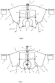
Figure 1 shows a longitudinal section of the apparatus; -
Figure 2 shows the apparatus for remote performing operations in initial state "on earth" -
Figure 3 shows the apparatus for remote performing operations "in flight"; -
Figure 4 shows the apparatus for remote performing operations "on wire" - The apparatus consists of a flying-lifting facility with
motors 1 mounted on aframe 2 provided with asleeve 3. Thesleeve 3 is movably seated on aguide 4 mounted on anexecution unit 5. Axis of the sleeve coincides with a vertical line passing through the center of mass of the execution unit. Adjustable upper and lower stop members are installed at the top and at the base of theguide 4, respectively. Theexecution unit 5 is provided with an operating member 8 - a magnetic head of a magnetic flaw detector, the head made as a cylinder (yoke) consisting of two half-cylinders interconnected by anaxle 9. - The half-cylinders of the magnetic head are connected by means of
rods 10 and bell-crank levers 11 to theframe 2 of the flying-lifting facility. - In addition, the
execution unit 5 is provided withsupports 12 andwheeled transportation facility 13 for moving it along awire 14. - In the initial position "on earth" (
FIG. 1 ), theexecution unit 5 stands "on earth" (FIG. 1 ) by resting on thesupports 12. Thesleeve 3 together with theframe 2 of the flying-lifting facility under the action of gravitational force are in the lower position at theadjustable stop member 7. The yoke of the magnetic head 8 (operating member) is in the closed position. - When the
motors 1 of the flying-lifting facility are powered on, theframe 2 together with thesleeve 3 begins to rise upward along theguide 4 to the adjustableupper stop member 6. When theframe 2 is moved upward, therods 10 and thelevers 11 open the magnetic head 8. When thesleeve 3 abuts against the adjustableupper stop member 6, a process of lifting and carrying theexecution unit 5 to the lightning-protection wire 14 begins (FIG. 3 ). - While landing on the wire 14 (
FIG. 4 ), the opened magnetic head 8 is moved downward, the wire enters the head until the wire abuts against the head upper part with a narrow opening (less than the diameter of the wire). At the same time, the wheels of thetransportation facility 13 rest on thewire 14, theexecution unit 5 stops to move down and the flying-lifting facility continues to move down under the action of gravitational force, the magnetic head is being closed (rolling forces of the half-cylinders), and thesleeve 3 reaches thelower stop member 7. Theexecution unit 5 is ready to perform monitoring of thewire 14. Upon completion of the monitoring performed by moving the magnetic head 8 along the entire length of thewire 14 bywheeled transportation facility 13, the motors of the flying-lifting facility are powered on. At this time, the flying-lifting facility starts to rise (thesleeve 3 slides along the guide 4), and rods 10 and levers 11 open the magnetic head 8. Thesleeve 3 abuts against the upperadjustable stop member 6 and lifting of theexecution unit 5 is started for repositioning it into a new worksite. - In case any failure occurs, for example, even if power supplying of the motor of the flying-lifting facility fails, the apparatus may be easily removed from the lightning-protection wire by lifting it upwards by the
frame 2 of the flying-lifting facility. - According to the present method and apparatus for performing thereof, in order to open the operating member of the apparatus for remote performing operations, the lifting force of the motors of the flying-lifting facility at takeoff is used, and when landing in order to close the execution member, the gravitational force the facility is used, which influences the operating member by means of movement of the flying-lifting facility and execution unit relative to each other.
- The advantages of the present method and the apparatus for performing thereof are:
- the simplified design;
- the improved reliability of operation;
- the increased safety of operation.
-
- patcit 1: Specification of invention to the Patent
RU 2390468 - patcit 2: Specification of invention to the Patent
RU 2223803 - patcit 3: Specification of invention to the Patent
RU25580021
Claims (2)
- Method for grasping a power transmission line conductor by an operating member of an execution unit of an apparatus for remote monitoring equipped with a flying-lifting facility for being carried to a worksite, characterized by
using, on takeoff, a lifting force of the flying-lifting facility to open the operating member - a magnetic head, and
using, on landing on the conductor, a gravitational force of the flying-lifting facility to close the magnetic head,
wherein the forces influence the opening-closing motion due to movements of the flying-lifting facility relative to the execution unit. - Apparatus for remote monitoring power transmission lines, the apparatus including a flying-lifting facility, an execution unit comprising a facility for moving along a wire and an operating member - a magnetic head of a magnetic flaw detector, characterized in that
the flying-lifting facility is provided with a system of rods and levers connected with the magnetic head, and a sleeve slidably seated on a guide of the execution unit, wherein the guide is provided in its upper part and at its base with adjustable stop members - travel limiters of the flying-lifting facility relative to the execution unit, and the axis of the guide coincides with a vertical line passing through the centre of mass of the execution unit.
Applications Claiming Priority (2)
| Application Number | Priority Date | Filing Date | Title |
|---|---|---|---|
| RU2018106097A RU2683417C1 (en) | 2018-02-19 | 2018-02-19 | Method of capturing power line wires with working body of executive unit of device for remote control equipped for delivery thereof to place of work by aircraft lifting means, and device therefor |
| PCT/RU2019/050015 WO2019160453A1 (en) | 2018-02-19 | 2019-02-09 | Method of gripping an electrical transmission line for remote monitoring |
Publications (2)
| Publication Number | Publication Date |
|---|---|
| EP3633396A1 true EP3633396A1 (en) | 2020-04-08 |
| EP3633396A4 EP3633396A4 (en) | 2021-03-17 |
Family
ID=66089658
Family Applications (1)
| Application Number | Title | Priority Date | Filing Date |
|---|---|---|---|
| EP19753734.3A Withdrawn EP3633396A4 (en) | 2018-02-19 | 2019-02-09 | Method of gripping an electrical transmission line for remote monitoring |
Country Status (6)
| Country | Link |
|---|---|
| US (1) | US20210123965A1 (en) |
| EP (1) | EP3633396A4 (en) |
| CN (1) | CN110799847A (en) |
| CA (1) | CA3068217A1 (en) |
| RU (1) | RU2683417C1 (en) |
| WO (1) | WO2019160453A1 (en) |
Cited By (2)
| Publication number | Priority date | Publication date | Assignee | Title |
|---|---|---|---|---|
| US11368002B2 (en) | 2016-11-22 | 2022-06-21 | Hydro-Quebec | Unmanned aerial vehicle for monitoring an electrical line |
| US12097956B2 (en) | 2021-04-30 | 2024-09-24 | Hydro-Quebec | Drone with tool positioning system |
Families Citing this family (3)
| Publication number | Priority date | Publication date | Assignee | Title |
|---|---|---|---|---|
| RU197328U1 (en) * | 2019-09-05 | 2020-04-21 | Открытое Акционерное Общество "Межрегиональная Распределительная Сетевая Компания Урала" (Оао "Мрск Урала") | Device for remote magnetic scanning of a metal rope |
| RU2731846C1 (en) * | 2020-02-21 | 2020-09-08 | Сергей Григорьевич Кузовников | Device for diagnostics of overhead transmission lines |
| WO2023132758A1 (en) * | 2022-01-10 | 2023-07-13 | Общество с ограниченной ответственностью "Лаборатория будущего" | Method for greasing an earth wire or conductor of an overhead power line |
Family Cites Families (17)
| Publication number | Priority date | Publication date | Assignee | Title |
|---|---|---|---|---|
| RU2223803C1 (en) | 2002-10-25 | 2004-02-20 | Кирюшин Игорь Герольдович | Method of injured person detection and useful loads delivery during search-and-rescue activity |
| GB0311138D0 (en) * | 2003-05-15 | 2003-06-18 | Univ Wales Bangor | Improvements in or relating to diagnostics |
| RU2390468C2 (en) | 2007-12-25 | 2010-05-27 | Юрий Георгиевич Данилин | Method of emergent delivery of payload to isolated object |
| RU2421746C1 (en) * | 2010-02-10 | 2011-06-20 | Ооо Научно-Производственное Предприятие "Энергоконсалт" | Diagnostic method of high-voltage power line |
| JP5237472B2 (en) * | 2010-02-10 | 2013-07-17 | エレクトリック パワー リサーチ インスティテュート,インク. | Line inspection robot and system |
| CN102412530B (en) * | 2011-12-23 | 2014-04-09 | 北京国网富达科技发展有限责任公司 | Line navigation amphibious power circuit comprehensive maintenance robot and circuit maintenance method thereof |
| WO2015026302A1 (en) * | 2013-08-23 | 2015-02-26 | Defence Technology Institute (Public Organization) | Vertical take off and landing unmanned aerial vehicle with twin yaw control system |
| RU2558002C1 (en) * | 2014-02-03 | 2015-07-27 | Общество с ограниченной ответственностью "Лаборатория будущего" | Device for diagnostics of overhead power transmission lines and its component |
| US9932110B2 (en) * | 2014-07-22 | 2018-04-03 | Jonathan McNally | Method for installing an object using an unmanned aerial vehicle |
| CN104384118B (en) * | 2014-09-16 | 2016-08-24 | 国家电网公司 | Band electrical clean-up foreign body mechanical arm hands |
| WO2016103264A1 (en) * | 2014-12-24 | 2016-06-30 | Noam Cohen | A method and apparatus for extending range of small unmanned aerial vehicles - multicopters |
| US9878787B2 (en) * | 2015-07-15 | 2018-01-30 | Elwha Llc | System and method for operating unmanned aircraft |
| KR20170078434A (en) * | 2015-12-29 | 2017-07-07 | 주식회사 페라리스파워 | Unmanned aerial vehicle device charge by electric wire and charging method thereof |
| CN106992469B (en) * | 2017-05-31 | 2018-08-14 | 长沙理工大学 | A kind of hot line maintenance robot and its upper and lower line control method |
| KR101815091B1 (en) * | 2017-06-13 | 2018-01-04 | 강종수 | An unmanned aerial vehicle for inspecting of high-voltage line and a method for controlling the same |
| CN107380415B (en) * | 2017-06-21 | 2019-06-18 | 浙江大学宁波理工学院 | A kind of aircraft of electric power line inspection |
| CN107458617A (en) * | 2017-08-31 | 2017-12-12 | 四川省冶地工程勘察设计有限公司 | A kind of unmanned plane surveying and mapping data harvester |
-
2018
- 2018-02-19 RU RU2018106097A patent/RU2683417C1/en active
-
2019
- 2019-02-09 CA CA3068217A patent/CA3068217A1/en not_active Abandoned
- 2019-02-09 WO PCT/RU2019/050015 patent/WO2019160453A1/en unknown
- 2019-02-09 EP EP19753734.3A patent/EP3633396A4/en not_active Withdrawn
- 2019-02-09 US US16/625,481 patent/US20210123965A1/en not_active Abandoned
- 2019-02-09 CN CN201980003224.9A patent/CN110799847A/en active Pending
Cited By (2)
| Publication number | Priority date | Publication date | Assignee | Title |
|---|---|---|---|---|
| US11368002B2 (en) | 2016-11-22 | 2022-06-21 | Hydro-Quebec | Unmanned aerial vehicle for monitoring an electrical line |
| US12097956B2 (en) | 2021-04-30 | 2024-09-24 | Hydro-Quebec | Drone with tool positioning system |
Also Published As
| Publication number | Publication date |
|---|---|
| CN110799847A (en) | 2020-02-14 |
| CA3068217A1 (en) | 2019-08-22 |
| EP3633396A4 (en) | 2021-03-17 |
| RU2683417C1 (en) | 2019-03-28 |
| WO2019160453A1 (en) | 2019-08-22 |
| US20210123965A1 (en) | 2021-04-29 |
Similar Documents
| Publication | Publication Date | Title |
|---|---|---|
| EP3633396A1 (en) | Method of gripping an electrical transmission line for remote monitoring | |
| EP3104184A1 (en) | Method and apparatus for locating faults in overhead power transmission lines | |
| CN113182936B (en) | Structure repair apparatus and method using unmanned aerial vehicle | |
| CN104386250B (en) | Multi-rotor-wing patrolling aircraft and power transmission line patrolling system | |
| CN204355272U (en) | A kind of many rotors patrol and examine aircraft and power transmission line polling system | |
| KR102178393B1 (en) | Transmission line monitoring apparatus using unmanned aerial vehicles | |
| EP3253705B1 (en) | Transport system with an unmanned aerial vehicle and a gripping device for picking up piece goods from above, and method for picking up piece goods using this transport system | |
| DE102015115184A1 (en) | Apparatus and method for treating containers and packages with aircraft for monitoring | |
| RU2717136C1 (en) | Device for diagnostics of overhead transmission lines | |
| EP3377701B1 (en) | Method and device for securing motion of a motor vehicle on an inclined ramp | |
| DE102009015648B4 (en) | Arrangement for carrying out maintenance work on aircraft | |
| CN111879554A (en) | Sampling device and method for monitoring loose rock-soil mass based on unmanned aerial vehicle | |
| CN103869811B (en) | The remote control of a kind of quadrotor and the monitoring method of servosignal | |
| CN218298368U (en) | Unmanned aerial vehicle inspection device | |
| RU2731846C1 (en) | Device for diagnostics of overhead transmission lines | |
| DE102016201159A1 (en) | Automated inspection of infrastructure elements | |
| Marredo et al. | A Novel Unmanned Aerial System for Power Line Inspection and Maintenance Operations | |
| EP3071372A1 (en) | Operating device and operating method | |
| CN107834427A (en) | A kind of power transmission line crusing robot control system and its method based on unmanned plane | |
| CN106711572A (en) | Airborne SAR antenna tower type operation orbit | |
| DE102020214021A1 (en) | Method for operating a crane system and crane system | |
| Espinosa Peralta et al. | ROSE: Robot for Automatic Spacer Installation in Overhead Power Lines | |
| CN113335543B (en) | On-line monitoring power station equipment based on unmanned aerial vehicle in flight | |
| EP3887098B1 (en) | Robot arrangement having buoyancy body for filling with a gas lighter than air | |
| Scaff et al. | Automatic elevator for assisting maintenance of distribution power line-Control system |
Legal Events
| Date | Code | Title | Description |
|---|---|---|---|
| STAA | Information on the status of an ep patent application or granted ep patent |
Free format text: STATUS: THE INTERNATIONAL PUBLICATION HAS BEEN MADE |
|
| PUAI | Public reference made under article 153(3) epc to a published international application that has entered the european phase |
Free format text: ORIGINAL CODE: 0009012 |
|
| STAA | Information on the status of an ep patent application or granted ep patent |
Free format text: STATUS: REQUEST FOR EXAMINATION WAS MADE |
|
| 17P | Request for examination filed |
Effective date: 20191231 |
|
| AK | Designated contracting states |
Kind code of ref document: A1 Designated state(s): AL AT BE BG CH CY CZ DE DK EE ES FI FR GB GR HR HU IE IS IT LI LT LU LV MC MK MT NL NO PL PT RO RS SE SI SK SM TR |
|
| AX | Request for extension of the european patent |
Extension state: BA ME |
|
| A4 | Supplementary search report drawn up and despatched |
Effective date: 20210215 |
|
| RIC1 | Information provided on ipc code assigned before grant |
Ipc: B64C 39/02 20060101ALI20210209BHEP Ipc: G01R 31/08 20200101AFI20210209BHEP |
|
| DAV | Request for validation of the european patent (deleted) | ||
| DAX | Request for extension of the european patent (deleted) | ||
| STAA | Information on the status of an ep patent application or granted ep patent |
Free format text: STATUS: THE APPLICATION IS DEEMED TO BE WITHDRAWN |
|
| 18D | Application deemed to be withdrawn |
Effective date: 20210901 |