EP3633221A1 - Clutch and vehicle power transmission structure - Google Patents
Clutch and vehicle power transmission structure Download PDFInfo
- Publication number
- EP3633221A1 EP3633221A1 EP17924293.8A EP17924293A EP3633221A1 EP 3633221 A1 EP3633221 A1 EP 3633221A1 EP 17924293 A EP17924293 A EP 17924293A EP 3633221 A1 EP3633221 A1 EP 3633221A1
- Authority
- EP
- European Patent Office
- Prior art keywords
- engagement element
- clutch
- torque
- input shaft
- output shaft
- Prior art date
- Legal status (The legal status is an assumption and is not a legal conclusion. Google has not performed a legal analysis and makes no representation as to the accuracy of the status listed.)
- Granted
Links
Images





Classifications
-
- F—MECHANICAL ENGINEERING; LIGHTING; HEATING; WEAPONS; BLASTING
- F16—ENGINEERING ELEMENTS AND UNITS; GENERAL MEASURES FOR PRODUCING AND MAINTAINING EFFECTIVE FUNCTIONING OF MACHINES OR INSTALLATIONS; THERMAL INSULATION IN GENERAL
- F16D—COUPLINGS FOR TRANSMITTING ROTATION; CLUTCHES; BRAKES
- F16D21/00—Systems comprising a plurality of actuated clutches
- F16D21/08—Serially-arranged clutches interconnecting two shafts only when all the clutches are engaged
-
- F—MECHANICAL ENGINEERING; LIGHTING; HEATING; WEAPONS; BLASTING
- F16—ENGINEERING ELEMENTS AND UNITS; GENERAL MEASURES FOR PRODUCING AND MAINTAINING EFFECTIVE FUNCTIONING OF MACHINES OR INSTALLATIONS; THERMAL INSULATION IN GENERAL
- F16D—COUPLINGS FOR TRANSMITTING ROTATION; CLUTCHES; BRAKES
- F16D41/00—Freewheels or freewheel clutches
- F16D41/12—Freewheels or freewheel clutches with hinged pawl co-operating with teeth, cogs, or the like
- F16D41/125—Freewheels or freewheel clutches with hinged pawl co-operating with teeth, cogs, or the like the pawl movement having an axial component
-
- B—PERFORMING OPERATIONS; TRANSPORTING
- B60—VEHICLES IN GENERAL
- B60K—ARRANGEMENT OR MOUNTING OF PROPULSION UNITS OR OF TRANSMISSIONS IN VEHICLES; ARRANGEMENT OR MOUNTING OF PLURAL DIVERSE PRIME-MOVERS IN VEHICLES; AUXILIARY DRIVES FOR VEHICLES; INSTRUMENTATION OR DASHBOARDS FOR VEHICLES; ARRANGEMENTS IN CONNECTION WITH COOLING, AIR INTAKE, GAS EXHAUST OR FUEL SUPPLY OF PROPULSION UNITS IN VEHICLES
- B60K6/00—Arrangement or mounting of plural diverse prime-movers for mutual or common propulsion, e.g. hybrid propulsion systems comprising electric motors and internal combustion engines
- B60K6/20—Arrangement or mounting of plural diverse prime-movers for mutual or common propulsion, e.g. hybrid propulsion systems comprising electric motors and internal combustion engines the prime-movers consisting of electric motors and internal combustion engines, e.g. HEVs
- B60K6/22—Arrangement or mounting of plural diverse prime-movers for mutual or common propulsion, e.g. hybrid propulsion systems comprising electric motors and internal combustion engines the prime-movers consisting of electric motors and internal combustion engines, e.g. HEVs characterised by apparatus, components or means specially adapted for HEVs
- B60K6/38—Arrangement or mounting of plural diverse prime-movers for mutual or common propulsion, e.g. hybrid propulsion systems comprising electric motors and internal combustion engines the prime-movers consisting of electric motors and internal combustion engines, e.g. HEVs characterised by apparatus, components or means specially adapted for HEVs characterised by the driveline clutches
- B60K6/387—Actuated clutches, i.e. clutches engaged or disengaged by electric, hydraulic or mechanical actuating means
-
- F—MECHANICAL ENGINEERING; LIGHTING; HEATING; WEAPONS; BLASTING
- F16—ENGINEERING ELEMENTS AND UNITS; GENERAL MEASURES FOR PRODUCING AND MAINTAINING EFFECTIVE FUNCTIONING OF MACHINES OR INSTALLATIONS; THERMAL INSULATION IN GENERAL
- F16D—COUPLINGS FOR TRANSMITTING ROTATION; CLUTCHES; BRAKES
- F16D11/00—Clutches in which the members have interengaging parts
- F16D11/14—Clutches in which the members have interengaging parts with clutching members movable only axially
-
- F—MECHANICAL ENGINEERING; LIGHTING; HEATING; WEAPONS; BLASTING
- F16—ENGINEERING ELEMENTS AND UNITS; GENERAL MEASURES FOR PRODUCING AND MAINTAINING EFFECTIVE FUNCTIONING OF MACHINES OR INSTALLATIONS; THERMAL INSULATION IN GENERAL
- F16D—COUPLINGS FOR TRANSMITTING ROTATION; CLUTCHES; BRAKES
- F16D13/00—Friction clutches
- F16D13/22—Friction clutches with axially-movable clutching members
- F16D13/38—Friction clutches with axially-movable clutching members with flat clutching surfaces, e.g. discs
- F16D13/52—Clutches with multiple lamellae ; Clutches in which three or more axially moveable members are fixed alternately to the shafts to be coupled and are pressed from one side towards an axially-located member
-
- F—MECHANICAL ENGINEERING; LIGHTING; HEATING; WEAPONS; BLASTING
- F16—ENGINEERING ELEMENTS AND UNITS; GENERAL MEASURES FOR PRODUCING AND MAINTAINING EFFECTIVE FUNCTIONING OF MACHINES OR INSTALLATIONS; THERMAL INSULATION IN GENERAL
- F16D—COUPLINGS FOR TRANSMITTING ROTATION; CLUTCHES; BRAKES
- F16D41/00—Freewheels or freewheel clutches
- F16D41/12—Freewheels or freewheel clutches with hinged pawl co-operating with teeth, cogs, or the like
- F16D41/14—Freewheels or freewheel clutches with hinged pawl co-operating with teeth, cogs, or the like the effective stroke of the pawl being adjustable
-
- F—MECHANICAL ENGINEERING; LIGHTING; HEATING; WEAPONS; BLASTING
- F16—ENGINEERING ELEMENTS AND UNITS; GENERAL MEASURES FOR PRODUCING AND MAINTAINING EFFECTIVE FUNCTIONING OF MACHINES OR INSTALLATIONS; THERMAL INSULATION IN GENERAL
- F16D—COUPLINGS FOR TRANSMITTING ROTATION; CLUTCHES; BRAKES
- F16D41/00—Freewheels or freewheel clutches
- F16D41/12—Freewheels or freewheel clutches with hinged pawl co-operating with teeth, cogs, or the like
- F16D41/16—Freewheels or freewheel clutches with hinged pawl co-operating with teeth, cogs, or the like the action being reversible
-
- F—MECHANICAL ENGINEERING; LIGHTING; HEATING; WEAPONS; BLASTING
- F16—ENGINEERING ELEMENTS AND UNITS; GENERAL MEASURES FOR PRODUCING AND MAINTAINING EFFECTIVE FUNCTIONING OF MACHINES OR INSTALLATIONS; THERMAL INSULATION IN GENERAL
- F16D—COUPLINGS FOR TRANSMITTING ROTATION; CLUTCHES; BRAKES
- F16D43/00—Automatic clutches
- F16D43/02—Automatic clutches actuated entirely mechanically
- F16D43/20—Automatic clutches actuated entirely mechanically controlled by torque, e.g. overload-release clutches, slip-clutches with means by which torque varies the clutching pressure
-
- F—MECHANICAL ENGINEERING; LIGHTING; HEATING; WEAPONS; BLASTING
- F16—ENGINEERING ELEMENTS AND UNITS; GENERAL MEASURES FOR PRODUCING AND MAINTAINING EFFECTIVE FUNCTIONING OF MACHINES OR INSTALLATIONS; THERMAL INSULATION IN GENERAL
- F16D—COUPLINGS FOR TRANSMITTING ROTATION; CLUTCHES; BRAKES
- F16D47/00—Systems of clutches, or clutches and couplings, comprising devices of types grouped under at least two of the following sets of groups: F16D1/00 - F16D9/00, F16D11/00 - F16D23/00, F16D25/00 - F16D29/00, F16D31/00 - F16D39/00, F16D41/00 - F16D45/00
-
- B—PERFORMING OPERATIONS; TRANSPORTING
- B60—VEHICLES IN GENERAL
- B60Y—INDEXING SCHEME RELATING TO ASPECTS CROSS-CUTTING VEHICLE TECHNOLOGY
- B60Y2200/00—Type of vehicle
- B60Y2200/90—Vehicles comprising electric prime movers
- B60Y2200/92—Hybrid vehicles
-
- B—PERFORMING OPERATIONS; TRANSPORTING
- B60—VEHICLES IN GENERAL
- B60Y—INDEXING SCHEME RELATING TO ASPECTS CROSS-CUTTING VEHICLE TECHNOLOGY
- B60Y2400/00—Special features of vehicle units
- B60Y2400/42—Clutches or brakes
- B60Y2400/421—Dog type clutches or brakes
-
- B—PERFORMING OPERATIONS; TRANSPORTING
- B60—VEHICLES IN GENERAL
- B60Y—INDEXING SCHEME RELATING TO ASPECTS CROSS-CUTTING VEHICLE TECHNOLOGY
- B60Y2400/00—Special features of vehicle units
- B60Y2400/42—Clutches or brakes
- B60Y2400/424—Friction clutches
- B60Y2400/4244—Friction clutches of wet type, e.g. using multiple lamellae
-
- F—MECHANICAL ENGINEERING; LIGHTING; HEATING; WEAPONS; BLASTING
- F16—ENGINEERING ELEMENTS AND UNITS; GENERAL MEASURES FOR PRODUCING AND MAINTAINING EFFECTIVE FUNCTIONING OF MACHINES OR INSTALLATIONS; THERMAL INSULATION IN GENERAL
- F16D—COUPLINGS FOR TRANSMITTING ROTATION; CLUTCHES; BRAKES
- F16D23/00—Details of mechanically-actuated clutches not specific for one distinct type
- F16D23/12—Mechanical clutch-actuating mechanisms arranged outside the clutch as such
- F16D2023/123—Clutch actuation by cams, ramps or ball-screw mechanisms
-
- F—MECHANICAL ENGINEERING; LIGHTING; HEATING; WEAPONS; BLASTING
- F16—ENGINEERING ELEMENTS AND UNITS; GENERAL MEASURES FOR PRODUCING AND MAINTAINING EFFECTIVE FUNCTIONING OF MACHINES OR INSTALLATIONS; THERMAL INSULATION IN GENERAL
- F16D—COUPLINGS FOR TRANSMITTING ROTATION; CLUTCHES; BRAKES
- F16D23/00—Details of mechanically-actuated clutches not specific for one distinct type
- F16D23/12—Mechanical clutch-actuating mechanisms arranged outside the clutch as such
-
- F—MECHANICAL ENGINEERING; LIGHTING; HEATING; WEAPONS; BLASTING
- F16—ENGINEERING ELEMENTS AND UNITS; GENERAL MEASURES FOR PRODUCING AND MAINTAINING EFFECTIVE FUNCTIONING OF MACHINES OR INSTALLATIONS; THERMAL INSULATION IN GENERAL
- F16D—COUPLINGS FOR TRANSMITTING ROTATION; CLUTCHES; BRAKES
- F16D28/00—Electrically-actuated clutches
-
- Y—GENERAL TAGGING OF NEW TECHNOLOGICAL DEVELOPMENTS; GENERAL TAGGING OF CROSS-SECTIONAL TECHNOLOGIES SPANNING OVER SEVERAL SECTIONS OF THE IPC; TECHNICAL SUBJECTS COVERED BY FORMER USPC CROSS-REFERENCE ART COLLECTIONS [XRACs] AND DIGESTS
- Y02—TECHNOLOGIES OR APPLICATIONS FOR MITIGATION OR ADAPTATION AGAINST CLIMATE CHANGE
- Y02T—CLIMATE CHANGE MITIGATION TECHNOLOGIES RELATED TO TRANSPORTATION
- Y02T10/00—Road transport of goods or passengers
- Y02T10/60—Other road transportation technologies with climate change mitigation effect
- Y02T10/62—Hybrid vehicles
Definitions
- the present invention relates to a clutch for transmitting or interrupting torque between an input shaft and an output shaft.
- the present invention also relates to a vehicle motive power transmission structure.
- a friction clutch for transmitting torque by using a friction force is known.
- a vehicle motive power transmission structure disclosed in Patent Literature 1 is such that a friction clutch is disposed between an input shaft and an output shaft in a situation where engine torque is inputted to the input shaft and electric motor torque is inputted to the output shaft.
- Patent Literature 1 Japanese Unexamined Patent Application Publication No. 2016-37252
- the above-mentioned conventional technology synchronizes the input shaft and the output shaft by applying a pressure load to a friction material of the friction clutch.
- the pressure load needs to be continuously applied in order to transmit torque with the input shaft coupled to the output shaft. This causes a problem where the continuous application of the pressure load results in an energy loss.
- a dog clutch achieves engagement by mechanical meshing.
- the dog clutch causes a problem where the input shaft and the output shaft cannot be synchronized.
- meshing is difficult to achieve when the input shaft and the output shaft significantly differ in relative speed and phase. This results in the generation of shock or an inability to transmit torque.
- An object of the present invention is to provide a clutch and a vehicle motive power transmission structure that are able to not only transmit torque smoothly even when the input shaft and the output shaft significantly differ in relative speed and phase, but also reduce the energy loss during torque transmission.
- a clutch according to the present invention selectively transmits or interrupts torque between an input shaft and an output shaft.
- the clutch includes a dog clutch and a friction clutch.
- the dog clutch transmits forward or reverse torque from the input shaft to the output shaft.
- the friction clutch is disposed in parallel with the dog clutch and adapted to transmit torque from the input shaft to the output shaft.
- a vehicle motive power transmission structure includes the clutch according to the present invention, and is configured such that engine torque is inputted to the input shaft while electric motor torque is inputted to the output shaft.
- the dog clutch transmits forward or reverse torque from the input shaft to the output shaft.
- the friction clutch which transmits torque from the input shaft to the output shaft, is disposed in parallel with the dog clutch. Therefore, even when the input shaft and the output shaft significantly differ in relative speed and phase, the friction clutch can be engaged to transmit torque smoothly.
- the friction clutch engages the input shaft with the output shaft and thus reduces the difference in relative speed and phase between the input and output shafts, the dog clutch can be easily engaged.
- no pressure load needs to be applied to the friction clutch.
- the dog clutch is configured such that a first member having a predetermined first surface is to be coupled to the output shaft.
- a second member having a second surface is to be coupled to the input shaft. The second surface axially opposes the first surface.
- a first engagement element disposed between the first surface and the second surface not only interrupts the transmission of reverse torque from the second member to the first member, but also engages the first member with the second member to transmit forward torque from the second member to the first member.
- a second engagement element disposed between the first surface and the second surface not only interrupts the transmission of forward torque from the second member to the first member, but also engages the first member with the second member to transmit reverse torque from the second member to the first member.
- the first engagement element and the second engagement element are respectively pressed by springs in an axial direction in which the first engagement element and the second engagement element become engaged. Therefore, when the difference in relative speed and phase between the input shaft and the output shaft is small, the first engagement element or the second engagement element engages with the first member and the second member. Consequently, in addition to the advantageous effects provided by Claim 1, it is possible to smoothly engage the dog clutch. Further, as the mechanism of the dog clutch can be simplified, it is possible to avoid an excessive axial dimension.
- a drive device deforms the spring in such a manner that the first engagement element and the second engagement element are unable to engage with each other. Therefore, it is possible to idle the second member with respect to the first member.
- the drive device simply needs to overcome the elastic force of the spring that presses the first engagement element or the second engagement element. This makes it possible to reduce the energy required of the drive device.
- the dog clutch includes a restriction member.
- the restriction member disables the first engagement member from engaging and enables the second engagement member to become engaged.
- the restriction member enables the first engagement element to become engaged. Consequently, in addition to the advantageous effects provided by Claim 2, it is possible to transmit forward torque from the second member to the first member through the first engagement element when the rotation speed of the second member is higher than that of the first member after the first engagement element is engaged.
- a transmission mechanism transmits the output of an actuator to the spring and the friction clutch.
- the actuator operates the friction clutch and the dog clutch. This eliminates the necessity of using actuators dedicated to the friction clutch and the dog clutch. Consequently, in addition to the advantageous effects provided by Claim 2 or 3, it is possible to downsize the clutch by an amount equivalent to the volume of unused dedicated actuators.
- the drive device first enables the second engagement element to become engaged, and then cancels the transmission of the output of the actuator to the friction clutch. This makes it possible to prevent the friction clutch from being engaged for an excessive period of time. Consequently, in addition to the advantageous effects provided by Claim 4, it is possible to reduce the energy required for friction clutch engagement.
- the transmission mechanism disables the drive device from operating the first engagement element and the second engagement element in a state where the friction clutch is disengaged. Consequently, in addition to the advantageous effects provided by Claim 4 or 5, it is possible to maintain a state where the first engagement element or the second engagement element is engaged with the first member and the second member without requiring the application of the pressure load to the friction clutch.
- a vehicle motive power transmission structure including the clutch defined in one of Claims 1 to 6.
- the torque of an engine is inputted to the input shaft, and the torque of an electric motor is inputted to the output shaft.
- the clutch is disposed between the input shaft and the output shaft. Consequently, even when the engine or the electric motor is started or stopped, it is possible to smoothly switch from one torque transmission path to another.
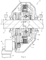
- Fig. 1 is an axial cross-sectional view illustrating the clutch 10 according to an embodiment of the present invention.
- the clutch 10 is a device that selectively transmits or interrupts torque between an input shaft 11 and an output shaft 12.
- the output shaft 12 is placed on the axis O of the input shaft 11 and pivotally disposed with respect to the input shaft 11.
- the torque of an engine 14 is inputted to the input shaft 11 through a transmission (not depicted), and the torque of an electric motor 15 is inputted to the output shaft 12.
- the clutch 10 includes a friction clutch 20 and a dog clutch 40.
- the friction clutch 20 and the dog clutch 40 are housed in a case 13 filled with a lubricating oil.
- the friction clutch 20 includes a clutch hub 21, a clutch drum 22, and a clutch plate 23.
- the clutch hub 21 is to be coupled to the input shaft 11.
- the clutch drum 22 is to be coupled to the output shaft 12.
- the clutch plate 23 is disposed between the clutch drum 22 and the clutch hub 21.
- the clutch hub 21 is coupled to the outer circumference of a second member 60 of the dog clutch 40.
- the clutch plate 23 is disposed on a radial overlap between the clutch hub 21 and the clutch drum 22, and axially movably supported by the clutch hub 21 and the clutch drum 22.
- a pressure member 24 adjusts the force that is exerted by the clutch plate 23 to fasten the clutch hub 21 to the clutch drum 22.
- An actuator 26 drives the pressure member 24 in order to move it in the direction of the axis O in which the clutch plate 23 is pressed, and thus increase the torque transmitted by the clutch plate 23.
- the friction clutch 20 is a wet multi-plate clutch (disc clutch) having a disc-shaped engagement surface.
- the actuator 26 includes an electric motor 27 and a reducer 28.
- the reducer 28 reduces the speed of the output from the electric motor 27.
- the reducer 28 is fastened to the case 13, and the electric motor 27 is fastened to the case 13 through a bracket (not depicted) .
- Rotary motion of the electric motor 27 is converted to linear motion by a ball cam 30.
- the ball cam 30 steplessly and accurately adjusts the fastening force of the clutch plate 23.
- the ball cam 30 includes a first plate 31, a second plate 32, and a ball 33.
- the first plate 31 is disposed on a driving side.
- the second plate 32 and the ball 33 are disposed on a reaction force side.
- the first plate 31 and the second plate 32 are rotatably supported by the outer circumference of the input shaft 11.
- the axial motion of the second plate 32 with respect to the input shaft 11 is restricted, and the first plate 31 faces the pressure member 24 through a thrust bearing.
- the tip of the first plate 31 meshes with a gear 34 that is connected to the output shaft of the reducer 28.
- a plurality of grooves having a predetermined phase difference are formed on cam surfaces that the first plate 31 and the second plate 32 mutually oppose, and are disposed on the same circumference centered around the axis O.
- the ball 33 is rotatably sandwiched between the cam surfaces.
- the dog clutch 40 includes a first member 50, the second member 60, a first engagement element 70, a second engagement element 80, springs 73, 83, and a transmission mechanism 100.
- the first member 50 is to be coupled to the output shaft 12.
- the second member 60 is to be coupled to the input shaft 11.
- the first engagement element 70 and the second engagement element 80 engage the first member 50 and the second member 60.
- the springs 73, 83 respectively press the first engagement element 70 and the second engagement element 80 in the direction of engaging the first member 50 and the second member 60.
- the transmission mechanism 100 disables the first engagement element 70 and the second engagement element 80 from engaging against the elastic force of the springs 73, 83.
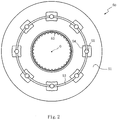
- Fig. 2 is a front view of the first member 50.
- the first member 50 has a first surface 51, and is substantially shaped like a ring.
- the first surface 51 is a flat surface orthogonal to the axis O.
- the first member 50 is to be coupled to the output shaft 12 by a spline 52 that is extended in the direction of the axis O.
- the first member 50 is configured such that a ring-shaped groove 53 is formed on the first surface 51.
- the first surface 51 is such that a plurality of concaves 54 (eight concaves in the present embodiment) are formed on the groove 53.
- the first member 50 is such that through-holes 55 are formed in the groove 53 within the concaves 54.
- the through-holes 55 penetrate the first member 50 in the direction of thickness (in the direction of the axis O).
- the concaves 54 are regions that the first engagement element 70 and the second engagement element 80 enter.
- the first engagement element 70 and the second engagement element 80 are swingably supported by the second member 60.
- the concaves 54 each have a substantially rectangular opening as viewed from front, and are formed at substantially equal intervals on the circumference of the groove 53.
- the radial width of the concaves 54 is slightly greater than the width of a main body 71 of the first engagement element 70 and the width of a main body 81 of the second engagement element 80 (these main bodies 71, 81 will be described later) . This permits the main bodies 71, 81 to enter the concaves 54.
- the groove 53 is a region for accommodating a ring member 56 (see Fig. 1 ) in such a manner as to permit the ring member 56 to move in the circumferential direction and in the direction of the axis O.
- the groove 53 is shaped like a rectangular cross-section in a cross-section containing the axis O.
- the through-holes 55 are regions into which pins 57 (see Fig. 1 ) slidably fit.
- the pins 57 transmit the force of the transmission mechanism 100 to the ring member 56.
- the ring member 56 restricts the swing of the first engagement element 70 and second engagement element 80.
- Fig. 3 (a) is a rear view of the second member 60.
- the second member 60 has a second surface 61, and is substantially shaped like a ring.
- the second surface 61 is a flat surface orthogonal to the axis O.
- the second surface 61 opposes the first surface 51 of the first member 50 in the direction of the axis O.
- the second member 60 is to be coupled to the input shaft 11 by a spline 62 that is extended in the direction of the axis O.
- the second member 60 is configured such that a ring-shaped wall 63 is formed around the second surface 61 so as to surround the second surface 61.
- a restriction member 90 (described later) is disposed on the second surface 61 inside the wall 63.
- the second surface 61 is configured such that a plurality of first concaves 64 and second concaves 65 (a total of eight concaves in the present embodiment) are formed at positions corresponding to those of the concaves 54 formed on the first surface 51 (see Fig. 2 ).
- the first engagement element 70 and the spring 73 are accommodated in the first concaves 64, and the second engagement element 80 and the spring 83 are accommodated in the second concaves 65.
- the first concaves 64 and the second concaves 65 are alternately disposed in the circumferential direction of the second surface 61.
- Fig. 3(b) is a rear view of the first engagement element 70.
- Fig. 3(c) is a side view of the first engagement element 70.
- the first engagement element 70 and the second engagement element 80 have the same configuration except that they differ in the orientation in which they are circumferentially disposed on the second member 60. Therefore, various sections of the first engagement element 70 will be described without describing those of the second engagement element 80.
- the first engagement element 70 is a substantially T-shaped plate as viewed from front, and includes a main body 71 and an arm 72.
- the main body 71 is substantially shaped like a rectangle as viewed from front.
- the arm 72 is substantially shaped like a stick, and protruded bilaterally from both edges of the end of the main body 71.
- the direction of torque transmitted by the first engagement element 70 is different from the direction of torque transmitted by the second engagement element 80.
- the first concaves 64 each include a main body accommodation section 64a and an arm accommodation section 64b.
- the main body accommodation section 64a is a shallow dent for accommodating the main body 71 of the first engagement element 70.
- the arm accommodation section 64b is a shallow dent for accommodating the arm 72.
- the arm accommodation section 64b is connected to the main body accommodation section 64a.
- the first concaves 64 are disposed such that the arm accommodation sections 64b are oriented in the inward and outward radial directions while the main body accommodation sections 64a are arranged in the circumferential direction.
- the first concaves 64 are configured such that a spring accommodation section 64c, which is a deeper dent than the main body accommodation section 64a, is connected to the main body accommodation section 64a disposed opposite the arm accommodation section 64b.
- the spring 73 (see Fig. 1 ) is accommodated in the spring accommodation section 64c.
- the second concaves 65 each include a main body accommodation section 65a and an arm accommodation section 65b.
- the main body accommodation section 65a is a shallow dent for accommodating the main body 81 of the second engagement element 80.
- the arm accommodation section 65b is a shallow dent for accommodating an arm 82.
- the arm accommodation section 65b is connected to the main body accommodation section 65a.
- the second concaves 65 are disposed such that the arm accommodation sections 65b are oriented in the inward and outward radial directions while the main body accommodation sections 65a are arranged in the circumferential direction.
- the second concaves 65 are configured such that a spring accommodation section 65c, which is a deeper dent than the main body accommodation section 65a, is connected to the main body accommodation section 65a disposed opposite the arm accommodation section 65b.
- the spring 83 (see Fig. 1 ) is accommodated in the spring accommodation section 65c.
- the springs 73, 83 are torsion coil springs.
- the present invention is not limited to such a configuration of the springs 73, 83.
- compression coil springs may obviously be used instead of torsion coil springs.
- the main body accommodation section 65a and arm accommodation section 65b of the second concaves 65 are disposed at positions opposing those of the main body accommodation section 64a and arm accommodation section 64b of the first concaves 64. Further, the main body accommodation section 65a and arm accommodation section 65b of the second concaves 65 are set to be greater in circumferential length than the main body accommodation section 64a and arm accommodation section 64b of the first concaves 64.
- the second concaves 60 are configured so that a circumferentially extended, substantially arc-shaped groove 66 is formed on a radially inward portion of the second surface 61.
- the groove 66 is a region where a coil spring 96 (described later) is disposed.
- the coil spring 96 presses the restriction member 90 (described later) in one circumferential direction.
- Fig. 4(a) is a rear view of the second member 60 that is obtained by assembling the first engagement element 70, the second engagement element 80, and the restriction member 90.
- Fig. 4(b) is a rear view of the second member 60 that is obtained by assembling the first engagement element 70, the second engagement element 80, and the restriction member 90 and by sliding the restriction member 90.
- Figs. 4(a) and 4(b) omit the spring accommodation sections 64c, 65c of the first concaves 64 and second concaves 65.
- the second member 60 is configured such that the first engagement element 70 and the second engagement element 80 are respectively disposed in the first concaves 64 and second concaves 65 formed on the second surface 61.
- the springs 73, 83 accommodated in the first concaves 64 and the second concaves 65 respectively swing the first engagement element 70 and the second engagement element 80 around the arms 72, 82.
- main body accommodation section 65a and arm accommodation section 65b of the second concaves 65 are set to be greater in circumferential length than the main body accommodation section 64a and arm accommodation section 64b of the first concaves 64, the main body 81 and arm 82 of the second engagement element 80 are able to move circumferentially within the main body accommodation section 65a and the arm accommodation section 65b.
- the restriction member 90 is a plate for restricting the swing of the first engagement element 70, and disposed between the second surface 61 of the second member 60 and the first surface 51 of the first member 50.
- the restriction member 90 includes a ring-shaped section 91, a plurality of first convexes 92 (four first convexes in the present embodiment), and a plurality of second convexes 94.
- the ring-shaped section 91 is shaped like a ring.
- the first convexes 92 protrude radially outward from the outer circumference of the ring-shaped section 91.
- the second convexes 94 protrude radially outward from the ring-shaped section 91 between the first convexes 92.
- the first convexes 92 each include a locking section 93 that covers the main body 71 of the first engagement element 70 accommodated in the first concaves 64 to restrict the swing of the first engagement element 70.
- the locking section 93 is formed in a stepwise manner so as to be positioned slightly away in the axial direction from the ring-shaped section 91 and the first convexes 92 (positioned forward as viewed in Fig. 4(a) ) by folding a radially outer portion of the first convexes 92 positioned in the same plane as the ring-shaped section 91.
- the second convexes 94 each include a contact section 95.
- the contact section 95 comes into contact with an arm 82 side end of the second engagement element 80 accommodated in the second concaves 65.
- the contact section 95 is formed on a circumferential edge of the second convexes 94.
- the restriction member 90 is configured such that the radial lengths (outside diameters) of the first convexes 92 and second convexes 94 are set to be smaller than the inside diameter of the ring member 56 (see Fig. 1 ). This setup is performed to avoid interference between the restriction member 90 and the ring member 56.
- the second member 60 is configured such that the coil spring 96 (see Fig. 6(a) ) is disposed in the groove 66 (see Fig. 3(a) ), which is formed on the radially inward portion of the second surface 61.
- a protrusion 97 (see Fig. 6(a) ) is disposed on the ring-shaped section 91.
- the protrusion 97 protrudes axially from an axial end face.
- the restriction member 90 stops at a position where the pressed second engagement element 80 comes into contact with a circumferential end of the second concaves 65. In this state, the main body 71 of the first engagement element 70 is covered with the locking section 93.
- Fig. 5 is a cross-sectional view of the clutch 10.
- the first engagement element 70 and the spring 73 are accommodated in the first concaves 64 (see Fig. 3(a) ) of the second member 60
- the second engagement element 80 and the spring 83 are accommodated in the second concaves 65 (see Fig. 3 (a) )
- the ring member 56 is accommodated in the groove 53 (see Fig. 2 ) of the first member 50.
- the first member 50 and the second member 60 are assembled in such a manner that the second surface 61 of the second member 60 faces the first surface 51 of the first member 50.
- the transmission mechanism 100 transmits the output of the actuator 26 to the dog clutch 40.
- the actuator 26 and the transmission mechanism 100 form a drive device.
- the transmission mechanism 100 includes the ball cam 30, the pressure member 24, a pin 101, and a spring 103.
- the pin 101 transmits the force of the pressure member 24 to an operating member 102.
- the spring 103 presses the operating member 102 toward the first member 50.
- the pin 101 penetrates the second member 60 and the clutch hub 21 in the direction of the axis O.
- the spring 103 depresses the pins 57 toward the second member 60 through the operating member 102.
- the elastic force exerted in the direction of the axis O by the spring 103 is greater than the elastic force exerted in the direction of the axis O by the springs 73, 83. Therefore, in a state where the ring member 56 pressed by the pins 57 has entered the concaves 54, the first engagement element 70 and the second engagement element 80 are unable to enter the concaves 54.
- the pressure member 24 is able to couple the input shaft 11 and the output shaft 12 by fastening the clutch plate 23. Further, the pressure member 24 moves the operating member 102 through the pin 101 while depressing the spring 103. This counteracts the elastic force of the spring 103 that acts on the ring member 56. Therefore, the springs 73, 83 cause the first engagement element 70 and the second engagement element 80 to enter the concaves 54.
- the lengths in the direction of the axis O of parts, such as the pin 101 and the operating member 102, are set such that the second engagement element 80 is able to enter the concaves 54 (the second engagement element 80 is able to become engaged) before the clutch plate 23 is fastened to couple the input shaft 11 and the output shaft 12 and synchronize the first member 50 and the second member 60.
- Fig. 6(a) is a schematic diagram illustrating the dog clutch 40 in a state where the swing of the first engagement element 70 and second engagement element 80 is restricted.
- Figs. 6(b) and 6(c) are schematic diagrams illustrating the dog clutch 40 in a state where the swing of the first engagement element 70 and second engagement element 80 is permitted.
- Fig. 7(a) is a schematic diagram illustrating the dog clutch 40 with the second engagement element 80 engaged in the concaves 54.
- Figs. 7(b) and 7(c) are schematic diagrams illustrating the dog clutch 40 in a state where the second member 60 relatively rotates in forward direction (in the direction of the arrows) with respect to the first member 50 while the swing of the first engagement element 70 and second engagement element 80 is permitted.
- Figs. 6 and 7 depict some portions of the first member 50 and second member 60 in a simplified manner. The lengths of the arrows in Figs. 6 and 7 indicate whether the forward rotation speeds of the first member 50 and second member 60 are high or low.
- the restriction member 90 pressed circumferentially by the coil spring 96 positions the locking section 93 between the first engagement element 70 and the first member 50 and brings the contact section 95 into contact with the second engagement element 80.
- the second engagement element 80 is then pressed circumferentially by the contact section 95 so that the arm 82 is fastened to the end of the arm accommodation section 65b.
- the first engagement element 70 and the second engagement element 80 are unable to enter the concaves 54 and become engaged. This interrupts the transmission of torque between the first member 50 and the second member 60.
- the second engagement element 80 swings. However, when the forward rotation speed of the second member 60 is higher than that of the first member 50, the second engagement element 80 is unable to become engaged in the concaves 54. This interrupts the transmission of torque between the first member 50 and the second member 60.
- the dog clutch 40 is a two-way clutch that causes the first engagement element 70 to transmit forward torque and causes the second engagement element 80 to transmit reverse torque.
- the actuator 26 is operated to move the pressure member 24 as depicted in Fig. 5 while the torque of the electric motor 15 is inputted to the output shaft 12.
- the pressure member 24 moves the operating member 102 through the pin 101 while depressing the spring 103. This counteracts the elastic force of the spring 103 that acts on the ring member 56. Therefore, the spring 83 causes the second engagement element 80 to enter the concaves 54.
- the friction clutch 20 becomes engaged. While allowing the clutch plate 23 to slide, the friction clutch 20 smoothly transmits the torque of the electric motor 15 to the input shaft 11 from the output shaft 12 to which the torque of the electric motor 15 is inputted.
- the friction clutch 20 is in a sliding state, the rotation speed of the first member 50 coupled to the output shaft 12 is higher than that of the second member 60 coupled to the input shaft 11. Therefore, the second engagement element 80 becomes engaged in the concaves 54.
- the second engagement element 80 pressed by the first member 50 presses the restriction member 90. As the locking section 93 positioned between the first engagement element 70 and the first member 50 moves out, the spring 73 causes the first engagement element 70 to enter the concaves 54. In this instance, no significant shock is created.
- the torque of the engine 14 is transmitted to the input shaft 11.
- the rotation speed of the second member 60 to be coupled to the input shaft 11 is higher than that of the first member 50
- the torque is transmitted from the second member 60 to the first member 50 through the first engagement element 70.
- the actuator 26 is operated to return the pressure member 24 to its previous position.
- the electric motor 15 may be stopped to allow the vehicle to run by using the engine 14. In such a case, electric power can be generated by the stopped electric motor 15.
- the elastic force of the spring 103 is unable to disengage the first engagement element 70. Therefore, even when the pressure member 24 returns to its previous position to disengage the friction clutch 20, the first engagement element 70 remains engaged.
- the role of the friction clutch 20 is to engage the first engagement element 70 by synchronizing the first member 50 and the second member 60. Therefore, after the first engagement element 70 is engaged, the friction clutch 20 may be disengaged. This makes it possible to reduce the time required for the actuator 26 to apply a load to the clutch plate 23. As a result, the energy consumed by the actuator 26 can be reduced.
- the transmission mechanism 100 disables the first engagement element 70 and the second engagement element 80 from becoming engaged by causing the spring 103 to apply, to the first engagement element 70 and the second engagement element 80, an elastic force exerted in a direction opposite the direction in which the pressure member 24 moves to fasten the friction clutch 20. Therefore, while the friction clutch 20 is engaged, the first member 50 and the second member 60 are permitted to engage with the first engagement element 70 or the second engagement element 80. Further, while the first engagement element 70 or the second engagement element 80 is engaged with the first member 50 and the second member 60, the actuator 26 is unable to operate the first engagement element 70 and the second engagement element 80 in a state where the friction clutch 20 is disengaged.
- the first engagement element 70 and the second engagement element 80 become engaged, the first engagement element 70 and the second engagement element 80 are able to remain engaged without requiring the application of a pressure load to the friction clutch 20. This reduces the energy required for the engagement of the friction clutch 20.
- the clutch 10 is configured such that the actuator 26 operates the friction clutch 20 and the dog clutch 40 through the transmission mechanism 100. Therefore, a dedicated actuator is not required for each of the friction clutch 20 and the dog clutch 40. Consequently, it is possible to reduce the size and weight of the clutch 10 by an amount equivalent to the size and weight of an unused dedicated actuator.
- first and second engagement elements 70, 80 are merely illustrative and not restrictive, and may be set as appropriate.
- the foregoing embodiment has been described on the assumption that a disc clutch is adopted as the friction clutch 20.
- the present invention is not limited to such a configuration.
- a different type of clutch may obviously be adopted as the friction clutch 20.
- a drum clutch or a cone clutch may be used as the friction clutch 20.
- a wet multi-plate clutch is adopted as the friction clutch 20 has been described
- the present invention is not limited to such a configuration.
- a dry clutch, a single-plate clutch, or a multi-disc clutch may obviously be adopted as the friction clutch 20.
- the friction clutch 20 described above functions when the electric motor 27 and the ball cam 30 are operated.
- the present invention is not limited to such a configuration.
- a hydraulically-operated clutch, a pneumatically-operated clutch, or a solenoid or other electromagnetic clutch may obviously be adopted as the friction clutch 20.
- the foregoing embodiment has been described on the assumption that the restriction member 90 for restricting the swing of the first engagement element 70 is disposed in the dog clutch 40.
- the present invention is not limited to such a configuration.
- the restriction member 90 may obviously be omitted from the dog clutch 40. In a case where the restriction member 90 is omitted, the circumferential length of the second concaves 65 is decreased to prevent the second engagement element 80 from sliding within the second concaves 65.
- the foregoing embodiment has been described on the assumption that the first engagement element 70 and the second engagement element 80 are pressed in the direction of the axis O through the ring member 56.
- the present invention is not limited to such a configuration.
- the first engagement element 70 and the second engagement element 80 may obviously be pressed in the direction of the axis O through the pins 57 by omitting the ring member 56, changing the tip shape of the pins 57, and changing the shapes of the first and second engagement elements 70, 80.
- first engagement element 70 and the second engagement element 80 have the same shape.
- present invention is not limited to such a configuration.
- the first engagement element 70 and the second engagement element 80 may obviously differ from each other in length, width, and thickness.
Landscapes
- Engineering & Computer Science (AREA)
- General Engineering & Computer Science (AREA)
- Mechanical Engineering (AREA)
- Chemical & Material Sciences (AREA)
- Combustion & Propulsion (AREA)
- Transportation (AREA)
- Mechanical Operated Clutches (AREA)
Abstract
Description
- The present invention relates to a clutch for transmitting or interrupting torque between an input shaft and an output shaft. The present invention also relates to a vehicle motive power transmission structure.
- A friction clutch for transmitting torque by using a friction force is known. A vehicle motive power transmission structure disclosed in Patent Literature 1 is such that a friction clutch is disposed between an input shaft and an output shaft in a situation where engine torque is inputted to the input shaft and electric motor torque is inputted to the output shaft.
- Patent Literature 1: Japanese Unexamined Patent Application Publication No.
2016-37252 - The above-mentioned conventional technology synchronizes the input shaft and the output shaft by applying a pressure load to a friction material of the friction clutch. However, the pressure load needs to be continuously applied in order to transmit torque with the input shaft coupled to the output shaft. This causes a problem where the continuous application of the pressure load results in an energy loss.
- Meanwhile, a dog clutch achieves engagement by mechanical meshing. However, the dog clutch causes a problem where the input shaft and the output shaft cannot be synchronized. Further, although no pressure load needs to be applied after synchronization, meshing is difficult to achieve when the input shaft and the output shaft significantly differ in relative speed and phase. This results in the generation of shock or an inability to transmit torque.
- The present invention has been made to solve the above problems. An object of the present invention is to provide a clutch and a vehicle motive power transmission structure that are able to not only transmit torque smoothly even when the input shaft and the output shaft significantly differ in relative speed and phase, but also reduce the energy loss during torque transmission.
- In accomplishing the above object, a clutch according to the present invention selectively transmits or interrupts torque between an input shaft and an output shaft. The clutch includes a dog clutch and a friction clutch. The dog clutch transmits forward or reverse torque from the input shaft to the output shaft. The friction clutch is disposed in parallel with the dog clutch and adapted to transmit torque from the input shaft to the output shaft.
- A vehicle motive power transmission structure according to the present invention includes the clutch according to the present invention, and is configured such that engine torque is inputted to the input shaft while electric motor torque is inputted to the output shaft.
- According to the clutch defined in Claim 1 of the present invention, the dog clutch transmits forward or reverse torque from the input shaft to the output shaft. The friction clutch, which transmits torque from the input shaft to the output shaft, is disposed in parallel with the dog clutch. Therefore, even when the input shaft and the output shaft significantly differ in relative speed and phase, the friction clutch can be engaged to transmit torque smoothly. When the friction clutch engages the input shaft with the output shaft and thus reduces the difference in relative speed and phase between the input and output shafts, the dog clutch can be easily engaged. When the friction clutch is disengaged after the dog clutch is engaged, no pressure load needs to be applied to the friction clutch. Consequently, it is possible to not only transmit torque smoothly even when the input shaft and the output shaft significantly differ in relative speed and phase, but also reduce the energy loss during torque transmission. Further, as the friction clutch and the dog clutch are disposed in parallel, it is possible to avoid an excessive axial dimension of the clutch.
- According to the clutch defined in Claim 2 of the present invention, the dog clutch is configured such that a first member having a predetermined first surface is to be coupled to the output shaft. A second member having a second surface is to be coupled to the input shaft. The second surface axially opposes the first surface. A first engagement element disposed between the first surface and the second surface not only interrupts the transmission of reverse torque from the second member to the first member, but also engages the first member with the second member to transmit forward torque from the second member to the first member. A second engagement element disposed between the first surface and the second surface not only interrupts the transmission of forward torque from the second member to the first member, but also engages the first member with the second member to transmit reverse torque from the second member to the first member.
- The first engagement element and the second engagement element are respectively pressed by springs in an axial direction in which the first engagement element and the second engagement element become engaged. Therefore, when the difference in relative speed and phase between the input shaft and the output shaft is small, the first engagement element or the second engagement element engages with the first member and the second member. Consequently, in addition to the advantageous effects provided by Claim 1, it is possible to smoothly engage the dog clutch. Further, as the mechanism of the dog clutch can be simplified, it is possible to avoid an excessive axial dimension.
- A drive device deforms the spring in such a manner that the first engagement element and the second engagement element are unable to engage with each other. Therefore, it is possible to idle the second member with respect to the first member. When disabling the first engagement element and the second engagement element from engaging with each other, the drive device simply needs to overcome the elastic force of the spring that presses the first engagement element or the second engagement element. This makes it possible to reduce the energy required of the drive device.
- According to the clutch defined in Claim 3 of the present invention, the dog clutch includes a restriction member. When the forward rotation speed of the second member is higher than that of the first member, the restriction member disables the first engagement member from engaging and enables the second engagement member to become engaged. When the forward rotation speed of the first member is higher than that of the second member while the second engagement element is engaged, the restriction member enables the first engagement element to become engaged. Consequently, in addition to the advantageous effects provided by Claim 2, it is possible to transmit forward torque from the second member to the first member through the first engagement element when the rotation speed of the second member is higher than that of the first member after the first engagement element is engaged.
- According to the clutch defined in Claim 4 of the present invention, a transmission mechanism transmits the output of an actuator to the spring and the friction clutch. The actuator operates the friction clutch and the dog clutch. This eliminates the necessity of using actuators dedicated to the friction clutch and the dog clutch. Consequently, in addition to the advantageous effects provided by Claim 2 or 3, it is possible to downsize the clutch by an amount equivalent to the volume of unused dedicated actuators.
- According to the clutch defined in Claim 5 of the present invention, the drive device first enables the second engagement element to become engaged, and then cancels the transmission of the output of the actuator to the friction clutch. This makes it possible to prevent the friction clutch from being engaged for an excessive period of time. Consequently, in addition to the advantageous effects provided by Claim 4, it is possible to reduce the energy required for friction clutch engagement.
- According to the clutch defined in Claim 6 of the present invention, while the first engagement element or the second engagement element is engaged with the first member and the second member, the transmission mechanism disables the drive device from operating the first engagement element and the second engagement element in a state where the friction clutch is disengaged. Consequently, in addition to the advantageous effects provided by Claim 4 or 5, it is possible to maintain a state where the first engagement element or the second engagement element is engaged with the first member and the second member without requiring the application of the pressure load to the friction clutch.
- According to Claim 7 of the present invention, there is provided a vehicle motive power transmission structure including the clutch defined in one of Claims 1 to 6. The torque of an engine is inputted to the input shaft, and the torque of an electric motor is inputted to the output shaft. The clutch is disposed between the input shaft and the output shaft. Consequently, even when the engine or the electric motor is started or stopped, it is possible to smoothly switch from one torque transmission path to another.
-
-
Fig. 1 is a cross-sectional view illustrating a clutch according to an embodiment of the present invention. -
Fig. 2 is a front view illustrating a first member. -
Fig. 3(a) is a rear view illustrating a second member.Fig. 3(b) is a rear view illustrating a first engagement element.Fig. 3(c) is a side view illustrating the first engagement element. -
Fig. 4 (a) is a rear view illustrating the second member that is obtained by assembling the first engagement element, a second engagement element, and a restriction member.Fig. 4(b) is a rear view illustrating the second member that is obtained by assembling the first engagement element, the second engagement element, and the restriction member and by sliding the restriction member. -
Fig. 5 is a cross-sectional view illustrating the clutch. -
Fig. 6 (a) is a schematic diagram illustrating a dog clutch in a state where the swing of the first and second engagement elements is restricted.Figs. 6(b) and 6(c) are schematic diagrams illustrating the dog clutch in a state where the swing of the first and second engagement elements is permitted. -
Fig. 7 (a) is a schematic diagram illustrating the dog clutch with the second engagement element engaged in a concave.Figs. 7(b) and 7(c) are schematic diagrams illustrating the dog clutch in a state where the second member relatively rotates in forward direction with respect to the first member while the swing of the first and second engagement elements is permitted. - Preferred embodiments of the present invention will now be described with reference to the accompanying drawings. First of all, a schematic configuration of a clutch 10 will be described with reference to
Fig. 1. Fig. 1 is an axial cross-sectional view illustrating the clutch 10 according to an embodiment of the present invention. - As illustrated in
Fig. 1 , the clutch 10 is a device that selectively transmits or interrupts torque between aninput shaft 11 and anoutput shaft 12. Theoutput shaft 12 is placed on the axis O of theinput shaft 11 and pivotally disposed with respect to theinput shaft 11. In the present embodiment, the torque of anengine 14 is inputted to theinput shaft 11 through a transmission (not depicted), and the torque of anelectric motor 15 is inputted to theoutput shaft 12. The clutch 10 includes afriction clutch 20 and adog clutch 40. Thefriction clutch 20 and thedog clutch 40 are housed in acase 13 filled with a lubricating oil. - The
friction clutch 20 includes aclutch hub 21, aclutch drum 22, and aclutch plate 23. Theclutch hub 21 is to be coupled to theinput shaft 11. Theclutch drum 22 is to be coupled to theoutput shaft 12. Theclutch plate 23 is disposed between theclutch drum 22 and theclutch hub 21. In the present embodiment, theclutch hub 21 is coupled to the outer circumference of asecond member 60 of thedog clutch 40. Theclutch plate 23 is disposed on a radial overlap between theclutch hub 21 and theclutch drum 22, and axially movably supported by theclutch hub 21 and theclutch drum 22. - A
pressure member 24 adjusts the force that is exerted by theclutch plate 23 to fasten theclutch hub 21 to theclutch drum 22. Aspring 25 disposed between theclutch hub 21 and theclutch drum 22 presses thepressure member 24 in the direction of releasing the transmission of torque. An actuator 26 drives thepressure member 24 in order to move it in the direction of the axis O in which theclutch plate 23 is pressed, and thus increase the torque transmitted by theclutch plate 23. In the present embodiment, thefriction clutch 20 is a wet multi-plate clutch (disc clutch) having a disc-shaped engagement surface. - The
actuator 26 includes anelectric motor 27 and areducer 28. Thereducer 28 reduces the speed of the output from theelectric motor 27. Thereducer 28 is fastened to thecase 13, and theelectric motor 27 is fastened to thecase 13 through a bracket (not depicted) . Rotary motion of theelectric motor 27 is converted to linear motion by aball cam 30. - The
ball cam 30 steplessly and accurately adjusts the fastening force of theclutch plate 23. Theball cam 30 includes afirst plate 31, asecond plate 32, and aball 33. Thefirst plate 31 is disposed on a driving side. Thesecond plate 32 and theball 33 are disposed on a reaction force side. Thefirst plate 31 and thesecond plate 32 are rotatably supported by the outer circumference of theinput shaft 11. The axial motion of thesecond plate 32 with respect to theinput shaft 11 is restricted, and thefirst plate 31 faces thepressure member 24 through a thrust bearing. The tip of thefirst plate 31 meshes with agear 34 that is connected to the output shaft of thereducer 28. A plurality of grooves having a predetermined phase difference are formed on cam surfaces that thefirst plate 31 and thesecond plate 32 mutually oppose, and are disposed on the same circumference centered around the axis O. Theball 33 is rotatably sandwiched between the cam surfaces. - In a case where the
friction clutch 20 is to be fastened, rotating thefirst plate 31 with respect to thesecond plate 32 through thegear 34 of thereducer 28 moves thefirst plate 31 toward thepressure member 24 while receiving a pressing force of theball 33. When thefirst plate 31 presses thepressure member 24 toward the axis O, thepressure member 24 presses theclutch plate 23. Meanwhile, in a case where thefriction clutch 20 is to be unfastened, rotating thegear 34 of thereducer 28 in an opposite direction moves thefirst plate 31 away from thepressure member 24. Thespring 25 then presses thepressure member 24 toward thefirst plate 31 by the amount of movement of thefirst plate 31. Therefore, thepressure member 24 decreases the force of pressing theclutch plate 23. - The
dog clutch 40 includes afirst member 50, thesecond member 60, afirst engagement element 70, asecond engagement element 80, springs 73, 83, and atransmission mechanism 100. Thefirst member 50 is to be coupled to theoutput shaft 12. Thesecond member 60 is to be coupled to theinput shaft 11. Thefirst engagement element 70 and thesecond engagement element 80 engage thefirst member 50 and thesecond member 60. Thesprings first engagement element 70 and thesecond engagement element 80 in the direction of engaging thefirst member 50 and thesecond member 60. Thetransmission mechanism 100 disables thefirst engagement element 70 and thesecond engagement element 80 from engaging against the elastic force of thesprings - The
first member 50 will now be described with reference toFig. 2. Fig. 2 is a front view of thefirst member 50. Thefirst member 50 has afirst surface 51, and is substantially shaped like a ring. Thefirst surface 51 is a flat surface orthogonal to the axis O. Thefirst member 50 is to be coupled to theoutput shaft 12 by aspline 52 that is extended in the direction of the axis O. - The
first member 50 is configured such that a ring-shapedgroove 53 is formed on thefirst surface 51. Thefirst surface 51 is such that a plurality of concaves 54 (eight concaves in the present embodiment) are formed on thegroove 53. Thefirst member 50 is such that through-holes 55 are formed in thegroove 53 within theconcaves 54. The through-holes 55 penetrate thefirst member 50 in the direction of thickness (in the direction of the axis O). - The
concaves 54 are regions that thefirst engagement element 70 and thesecond engagement element 80 enter. Thefirst engagement element 70 and thesecond engagement element 80 are swingably supported by thesecond member 60. Theconcaves 54 each have a substantially rectangular opening as viewed from front, and are formed at substantially equal intervals on the circumference of thegroove 53. The radial width of theconcaves 54 is slightly greater than the width of amain body 71 of thefirst engagement element 70 and the width of amain body 81 of the second engagement element 80 (thesemain bodies main bodies concaves 54. - The
groove 53 is a region for accommodating a ring member 56 (seeFig. 1 ) in such a manner as to permit thering member 56 to move in the circumferential direction and in the direction of the axis O. Thegroove 53 is shaped like a rectangular cross-section in a cross-section containing the axis O. The through-holes 55 are regions into which pins 57 (seeFig. 1 ) slidably fit. Thepins 57 transmit the force of thetransmission mechanism 100 to thering member 56. Thering member 56 restricts the swing of thefirst engagement element 70 andsecond engagement element 80. - The
second member 60 will now be described with reference toFig. 3 (a) . Fig. 3 (a) is a rear view of thesecond member 60. Thesecond member 60 has asecond surface 61, and is substantially shaped like a ring. Thesecond surface 61 is a flat surface orthogonal to the axis O. Thesecond surface 61 opposes thefirst surface 51 of thefirst member 50 in the direction of the axis O. Thesecond member 60 is to be coupled to theinput shaft 11 by aspline 62 that is extended in the direction of the axis O. - The
second member 60 is configured such that a ring-shapedwall 63 is formed around thesecond surface 61 so as to surround thesecond surface 61. A restriction member 90 (described later) is disposed on thesecond surface 61 inside thewall 63. Thesecond surface 61 is configured such that a plurality offirst concaves 64 and second concaves 65 (a total of eight concaves in the present embodiment) are formed at positions corresponding to those of theconcaves 54 formed on the first surface 51 (seeFig. 2 ). Thefirst engagement element 70 and thespring 73 are accommodated in thefirst concaves 64, and thesecond engagement element 80 and thespring 83 are accommodated in thesecond concaves 65. Thefirst concaves 64 and thesecond concaves 65 are alternately disposed in the circumferential direction of thesecond surface 61. - The
first engagement element 70 and thesecond engagement element 80 will now be described with reference toFigs. 3(b) and 3(c) . Fig. 3(b) is a rear view of thefirst engagement element 70.Fig. 3(c) is a side view of thefirst engagement element 70. Thefirst engagement element 70 and thesecond engagement element 80 have the same configuration except that they differ in the orientation in which they are circumferentially disposed on thesecond member 60. Therefore, various sections of thefirst engagement element 70 will be described without describing those of thesecond engagement element 80. - The
first engagement element 70 is a substantially T-shaped plate as viewed from front, and includes amain body 71 and anarm 72. Themain body 71 is substantially shaped like a rectangle as viewed from front. Thearm 72 is substantially shaped like a stick, and protruded bilaterally from both edges of the end of themain body 71. The direction of torque transmitted by thefirst engagement element 70 is different from the direction of torque transmitted by thesecond engagement element 80. - Returning to
Fig. 3(a) , the following description is given. Thefirst concaves 64 each include a mainbody accommodation section 64a and anarm accommodation section 64b. The mainbody accommodation section 64a is a shallow dent for accommodating themain body 71 of thefirst engagement element 70. Thearm accommodation section 64b is a shallow dent for accommodating thearm 72. Thearm accommodation section 64b is connected to the mainbody accommodation section 64a. Thefirst concaves 64 are disposed such that thearm accommodation sections 64b are oriented in the inward and outward radial directions while the mainbody accommodation sections 64a are arranged in the circumferential direction. Thefirst concaves 64 are configured such that aspring accommodation section 64c, which is a deeper dent than the mainbody accommodation section 64a, is connected to the mainbody accommodation section 64a disposed opposite thearm accommodation section 64b. The spring 73 (seeFig. 1 ) is accommodated in thespring accommodation section 64c. - The
second concaves 65 each include a mainbody accommodation section 65a and anarm accommodation section 65b. The mainbody accommodation section 65a is a shallow dent for accommodating themain body 81 of thesecond engagement element 80. Thearm accommodation section 65b is a shallow dent for accommodating anarm 82. Thearm accommodation section 65b is connected to the mainbody accommodation section 65a. Thesecond concaves 65 are disposed such that thearm accommodation sections 65b are oriented in the inward and outward radial directions while the mainbody accommodation sections 65a are arranged in the circumferential direction. Thesecond concaves 65 are configured such that aspring accommodation section 65c, which is a deeper dent than the mainbody accommodation section 65a, is connected to the mainbody accommodation section 65a disposed opposite thearm accommodation section 65b. The spring 83 (seeFig. 1 ) is accommodated in thespring accommodation section 65c. In the present embodiment, thesprings springs - The main
body accommodation section 65a andarm accommodation section 65b of thesecond concaves 65 are disposed at positions opposing those of the mainbody accommodation section 64a andarm accommodation section 64b of thefirst concaves 64. Further, the mainbody accommodation section 65a andarm accommodation section 65b of thesecond concaves 65 are set to be greater in circumferential length than the mainbody accommodation section 64a andarm accommodation section 64b of thefirst concaves 64. - The
second concaves 60 are configured so that a circumferentially extended, substantially arc-shapedgroove 66 is formed on a radially inward portion of thesecond surface 61. Thegroove 66 is a region where a coil spring 96 (described later) is disposed. Thecoil spring 96 presses the restriction member 90 (described later) in one circumferential direction. - The
restriction member 90 will now be described with reference toFigs. 4. Fig. 4(a) is a rear view of thesecond member 60 that is obtained by assembling thefirst engagement element 70, thesecond engagement element 80, and therestriction member 90.Fig. 4(b) is a rear view of thesecond member 60 that is obtained by assembling thefirst engagement element 70, thesecond engagement element 80, and therestriction member 90 and by sliding therestriction member 90. For ease of understanding,Figs. 4(a) and 4(b) omit thespring accommodation sections second concaves 65. - As illustrated in
Fig. 4(a) , thesecond member 60 is configured such that thefirst engagement element 70 and thesecond engagement element 80 are respectively disposed in the first concaves 64 andsecond concaves 65 formed on thesecond surface 61. Thesprings 73, 83 (seeFig. 1 ) accommodated in the first concaves 64 and thesecond concaves 65 respectively swing thefirst engagement element 70 and thesecond engagement element 80 around thearms body accommodation section 65a andarm accommodation section 65b of thesecond concaves 65 are set to be greater in circumferential length than the mainbody accommodation section 64a andarm accommodation section 64b of thefirst concaves 64, themain body 81 andarm 82 of thesecond engagement element 80 are able to move circumferentially within the mainbody accommodation section 65a and thearm accommodation section 65b. - The
restriction member 90 is a plate for restricting the swing of thefirst engagement element 70, and disposed between thesecond surface 61 of thesecond member 60 and thefirst surface 51 of thefirst member 50. Therestriction member 90 includes a ring-shapedsection 91, a plurality of first convexes 92 (four first convexes in the present embodiment), and a plurality ofsecond convexes 94. The ring-shapedsection 91 is shaped like a ring. Thefirst convexes 92 protrude radially outward from the outer circumference of the ring-shapedsection 91. Thesecond convexes 94 protrude radially outward from the ring-shapedsection 91 between thefirst convexes 92. - The
first convexes 92 each include alocking section 93 that covers themain body 71 of thefirst engagement element 70 accommodated in thefirst concaves 64 to restrict the swing of thefirst engagement element 70. The lockingsection 93 is formed in a stepwise manner so as to be positioned slightly away in the axial direction from the ring-shapedsection 91 and the first convexes 92 (positioned forward as viewed inFig. 4(a) ) by folding a radially outer portion of thefirst convexes 92 positioned in the same plane as the ring-shapedsection 91. Thesecond convexes 94 each include acontact section 95. Thecontact section 95 comes into contact with anarm 82 side end of thesecond engagement element 80 accommodated in thesecond concaves 65. Thecontact section 95 is formed on a circumferential edge of thesecond convexes 94. - The
restriction member 90 is configured such that the radial lengths (outside diameters) of the first convexes 92 andsecond convexes 94 are set to be smaller than the inside diameter of the ring member 56 (seeFig. 1 ). This setup is performed to avoid interference between therestriction member 90 and thering member 56. - The
second member 60 is configured such that the coil spring 96 (seeFig. 6(a) ) is disposed in the groove 66 (seeFig. 3(a) ), which is formed on the radially inward portion of thesecond surface 61. A protrusion 97 (seeFig. 6(a) ) is disposed on the ring-shapedsection 91. Theprotrusion 97 protrudes axially from an axial end face. When thecoil spring 96 presses theprotrusion 97 in one circumferential direction (clockwise as viewed inFig. 4 (a) ), thecontact section 95 of thesecond convexes 94 comes into contact with a circumferential end face of thearm 82 of thesecond engagement element 80. This causes thesecond engagement element 80 to be pressed in the circumferential direction. Therestriction member 90 stops at a position where the pressedsecond engagement element 80 comes into contact with a circumferential end of thesecond concaves 65. In this state, themain body 71 of thefirst engagement element 70 is covered with thelocking section 93. - When a load is applied to the
second engagement element 80 in the opposite circumferential direction (counterclockwise as viewed inFig. 4 (b) ) as depicted inFig. 4 (b) , thesecond engagement element 80 presses thecontact section 95 brought into contact with thesecond engagement element 80. In a case where the applied load is greater than the force of the coil spring 96 (seeFig. 6(a) ), thesecond engagement element 80 slides within thesecond concaves 65 so that therestriction member 90 rotates in the opposite circumferential direction (counterclockwise as viewed inFig. 4(b) ). This shifts the position of thelocking section 93 in the opposite circumferential direction (counterclockwise as viewed inFig. 4 (b) ) . As a result, thefirst engagement element 70 is released from the lockingsection 93. - The
dog clutch 40 will now be further described with reference toFigs. 1 and5. Fig. 5 is a cross-sectional view of the clutch 10. As depicted inFig. 1 , thefirst engagement element 70 and thespring 73 are accommodated in the first concaves 64 (seeFig. 3(a) ) of thesecond member 60, and thesecond engagement element 80 and thespring 83 are accommodated in the second concaves 65 (seeFig. 3 (a) ) . Meanwhile, thering member 56 is accommodated in the groove 53 (seeFig. 2 ) of thefirst member 50. Thefirst member 50 and thesecond member 60 are assembled in such a manner that thesecond surface 61 of thesecond member 60 faces thefirst surface 51 of thefirst member 50. - The
transmission mechanism 100 transmits the output of theactuator 26 to thedog clutch 40. Theactuator 26 and thetransmission mechanism 100 form a drive device. Thetransmission mechanism 100 includes theball cam 30, thepressure member 24, apin 101, and aspring 103. Thepin 101 transmits the force of thepressure member 24 to an operatingmember 102. Thespring 103 presses the operatingmember 102 toward thefirst member 50. Thepin 101 penetrates thesecond member 60 and theclutch hub 21 in the direction of the axis O. Thespring 103 depresses thepins 57 toward thesecond member 60 through the operatingmember 102. The elastic force exerted in the direction of the axis O by thespring 103 is greater than the elastic force exerted in the direction of the axis O by thesprings ring member 56 pressed by thepins 57 has entered theconcaves 54, thefirst engagement element 70 and thesecond engagement element 80 are unable to enter theconcaves 54. - Meanwhile, when the
actuator 26 is operated to move thefirst plate 31 of theball cam 30 toward thepressure member 24 as depicted inFig. 5 , thepressure member 24 is able to couple theinput shaft 11 and theoutput shaft 12 by fastening theclutch plate 23. Further, thepressure member 24 moves the operatingmember 102 through thepin 101 while depressing thespring 103. This counteracts the elastic force of thespring 103 that acts on thering member 56. Therefore, thesprings first engagement element 70 and thesecond engagement element 80 to enter theconcaves 54. - The lengths in the direction of the axis O of parts, such as the
pin 101 and the operatingmember 102, are set such that thesecond engagement element 80 is able to enter the concaves 54 (thesecond engagement element 80 is able to become engaged) before theclutch plate 23 is fastened to couple theinput shaft 11 and theoutput shaft 12 and synchronize thefirst member 50 and thesecond member 60. - An operation of the
dog clutch 40 will now be described with reference toFigs. 6 and7 .Fig. 6(a) is a schematic diagram illustrating thedog clutch 40 in a state where the swing of thefirst engagement element 70 andsecond engagement element 80 is restricted.Figs. 6(b) and 6(c) are schematic diagrams illustrating thedog clutch 40 in a state where the swing of thefirst engagement element 70 andsecond engagement element 80 is permitted. -
Fig. 7(a) is a schematic diagram illustrating thedog clutch 40 with thesecond engagement element 80 engaged in theconcaves 54.Figs. 7(b) and 7(c) are schematic diagrams illustrating thedog clutch 40 in a state where thesecond member 60 relatively rotates in forward direction (in the direction of the arrows) with respect to thefirst member 50 while the swing of thefirst engagement element 70 andsecond engagement element 80 is permitted. For ease of understanding,Figs. 6 and7 depict some portions of thefirst member 50 andsecond member 60 in a simplified manner. The lengths of the arrows inFigs. 6 and7 indicate whether the forward rotation speeds of thefirst member 50 andsecond member 60 are high or low. - As illustrated in
Fig. 6(a) , therestriction member 90 pressed circumferentially by thecoil spring 96 positions thelocking section 93 between thefirst engagement element 70 and thefirst member 50 and brings thecontact section 95 into contact with thesecond engagement element 80. Thesecond engagement element 80 is then pressed circumferentially by thecontact section 95 so that thearm 82 is fastened to the end of thearm accommodation section 65b. In a state where thering member 56 has entered theconcaves 54 of thefirst member 50, thefirst engagement element 70 and thesecond engagement element 80 are unable to enter theconcaves 54 and become engaged. This interrupts the transmission of torque between thefirst member 50 and thesecond member 60. - In a state where the
ring member 56 has exited theconcaves 54 of thefirst member 50 as depicted inFigs. 6(b) and 6(c) , thesecond engagement element 80 swings. However, when the forward rotation speed of thesecond member 60 is higher than that of thefirst member 50, thesecond engagement element 80 is unable to become engaged in theconcaves 54. This interrupts the transmission of torque between thefirst member 50 and thesecond member 60. - As depicted in
Fig. 7(a) , when thesecond engagement element 80 entering in theconcaves 54 is pressed in the circumferential direction in a case where the forward rotation speed of thefirst member 50 is higher than that of thesecond member 60, thecontact section 95 presses therestriction member 90 in the circumferential direction while depressing thecoil spring 96. When thelocking section 93 releases thefirst engagement element 70, thefirst engagement element 70 enters theconcaves 54 and becomes engaged as depicted inFig. 7(c) . When thesecond member 60 drives in forward direction, thefirst member 50 is driven through thefirst engagement element 70 so that torque is transmitted from thesecond member 60 to thefirst member 50. - When the
ring member 56 enters theconcaves 54, the first andsecond engagement elements concaves 54 are able to exit theconcaves 54 to interrupt the transmission of motive power between thefirst member 50 and thesecond member 60. Thedog clutch 40 is a two-way clutch that causes thefirst engagement element 70 to transmit forward torque and causes thesecond engagement element 80 to transmit reverse torque. - An exemplary operation performed by the clutch 10 in a vehicle motive power transmission structure for inputting the torque of the
engine 14 to theinput shaft 11 of the clutch 10 and inputting the torque of theelectric motor 15 to theoutput shaft 12 will now be described with reference toFigs. 1 and5 . - When a vehicle starts running and runs at low or medium speed, the
engine 14 stops to disengage thefriction clutch 20 anddog clutch 40 of the clutch 10 as depicted inFig. 1 . This allows the vehicle to start and run by using theelectric motor 15. - During an ordinary run, the
actuator 26 is operated to move thepressure member 24 as depicted inFig. 5 while the torque of theelectric motor 15 is inputted to theoutput shaft 12. Thepressure member 24 moves the operatingmember 102 through thepin 101 while depressing thespring 103. This counteracts the elastic force of thespring 103 that acts on thering member 56. Therefore, thespring 83 causes thesecond engagement element 80 to enter theconcaves 54. - When the
pressure member 24 moves, thefriction clutch 20 becomes engaged. While allowing theclutch plate 23 to slide, the friction clutch 20 smoothly transmits the torque of theelectric motor 15 to theinput shaft 11 from theoutput shaft 12 to which the torque of theelectric motor 15 is inputted. When thefriction clutch 20 is in a sliding state, the rotation speed of thefirst member 50 coupled to theoutput shaft 12 is higher than that of thesecond member 60 coupled to theinput shaft 11. Therefore, thesecond engagement element 80 becomes engaged in theconcaves 54. Thesecond engagement element 80 pressed by thefirst member 50 presses therestriction member 90. As thelocking section 93 positioned between thefirst engagement element 70 and thefirst member 50 moves out, thespring 73 causes thefirst engagement element 70 to enter theconcaves 54. In this instance, no significant shock is created. - Next, the torque of the
engine 14 is transmitted to theinput shaft 11. When the rotation speed of thesecond member 60 to be coupled to theinput shaft 11 is higher than that of thefirst member 50, the torque is transmitted from thesecond member 60 to thefirst member 50 through thefirst engagement element 70. Subsequently, in order to disengage thefriction clutch 20, theactuator 26 is operated to return thepressure member 24 to its previous position. This allows the vehicle to run by using theengine 14 and theelectric motor 15. In this instance, theelectric motor 15 may be stopped to allow the vehicle to run by using theengine 14. In such a case, electric power can be generated by the stoppedelectric motor 15. - While the
second member 60 drives to let thefirst engagement element 70 transmit torque, the elastic force of thespring 103 is unable to disengage thefirst engagement element 70. Therefore, even when thepressure member 24 returns to its previous position to disengage thefriction clutch 20, thefirst engagement element 70 remains engaged. The role of thefriction clutch 20 is to engage thefirst engagement element 70 by synchronizing thefirst member 50 and thesecond member 60. Therefore, after thefirst engagement element 70 is engaged, the friction clutch 20 may be disengaged. This makes it possible to reduce the time required for theactuator 26 to apply a load to theclutch plate 23. As a result, the energy consumed by theactuator 26 can be reduced. - The
transmission mechanism 100 disables thefirst engagement element 70 and thesecond engagement element 80 from becoming engaged by causing thespring 103 to apply, to thefirst engagement element 70 and thesecond engagement element 80, an elastic force exerted in a direction opposite the direction in which thepressure member 24 moves to fasten thefriction clutch 20. Therefore, while thefriction clutch 20 is engaged, thefirst member 50 and thesecond member 60 are permitted to engage with thefirst engagement element 70 or thesecond engagement element 80. Further, while thefirst engagement element 70 or thesecond engagement element 80 is engaged with thefirst member 50 and thesecond member 60, theactuator 26 is unable to operate thefirst engagement element 70 and thesecond engagement element 80 in a state where thefriction clutch 20 is disengaged. Therefore, when thefirst engagement element 70 and thesecond engagement element 80 become engaged, thefirst engagement element 70 and thesecond engagement element 80 are able to remain engaged without requiring the application of a pressure load to thefriction clutch 20. This reduces the energy required for the engagement of thefriction clutch 20. - When deceleration or braking is to be performed during an ordinary run, the
engine 14 and theelectric motor 15 are brought to a stop. A forward torque is transmitted from thefirst member 50, which is to be coupled to theoutput shaft 12, to thesecond member 60, which is to be coupled to theinput shaft 11, through thesecond engagement element 80. When the rotation speed of thefirst member 50 is substantially equal to that of thesecond member 60, the elastic force of thespring 103 defeats the force with which the first andsecond engagement elements concaves 54 and the elastic force of thesprings member 102, thepins 57, and thering member 56 toward thesecond member 60, and causes the first andsecond engagement elements concaves 54. This makes it possible to prevent the torque of theoutput shaft 12 from being decreased by simultaneous rotation of theinput shaft 11. Consequently, electric power loss can be reduced when electric power is generated by theoutput shaft 12 of theelectric motor 15. - The clutch 10 is configured such that the
actuator 26 operates thefriction clutch 20 and thedog clutch 40 through thetransmission mechanism 100. Therefore, a dedicated actuator is not required for each of thefriction clutch 20 and thedog clutch 40. Consequently, it is possible to reduce the size and weight of the clutch 10 by an amount equivalent to the size and weight of an unused dedicated actuator. - While the present invention has been described in terms of an embodiment, it should be understood that the present invention is not limited to the above-described embodiment. Persons skilled in the art will easily appreciate that various modifications may be made without departing from the scope and spirit of the present invention. For example, the number and shape of the first and
second engagement elements - The foregoing embodiment has been described on the assumption that a disc clutch is adopted as the
friction clutch 20. However, the present invention is not limited to such a configuration. A different type of clutch may obviously be adopted as thefriction clutch 20. For example, a drum clutch or a cone clutch may be used as thefriction clutch 20. Further, although a case where a wet multi-plate clutch is adopted as thefriction clutch 20 has been described, the present invention is not limited to such a configuration. For example, a dry clutch, a single-plate clutch, or a multi-disc clutch may obviously be adopted as thefriction clutch 20. Furthermore, the friction clutch 20 described above functions when theelectric motor 27 and theball cam 30 are operated. However, the present invention is not limited to such a configuration. For example, a hydraulically-operated clutch, a pneumatically-operated clutch, or a solenoid or other electromagnetic clutch may obviously be adopted as thefriction clutch 20. - The foregoing embodiment has been described on the assumption that the
restriction member 90 for restricting the swing of thefirst engagement element 70 is disposed in thedog clutch 40. However, the present invention is not limited to such a configuration. Therestriction member 90 may obviously be omitted from thedog clutch 40. In a case where therestriction member 90 is omitted, the circumferential length of thesecond concaves 65 is decreased to prevent thesecond engagement element 80 from sliding within thesecond concaves 65. - The foregoing embodiment has been described on the assumption that the
first engagement element 70 and thesecond engagement element 80 are pressed in the direction of the axis O through thering member 56. However, the present invention is not limited to such a configuration. Thefirst engagement element 70 and thesecond engagement element 80 may obviously be pressed in the direction of the axis O through thepins 57 by omitting thering member 56, changing the tip shape of thepins 57, and changing the shapes of the first andsecond engagement elements - The foregoing embodiment has been described on the assumption that the
first engagement element 70 and thesecond engagement element 80 have the same shape. However, the present invention is not limited to such a configuration. Thefirst engagement element 70 and thesecond engagement element 80 may obviously differ from each other in length, width, and thickness. -
- 10:
- clutch
- 11:
- input shaft
- 12:
- output shaft
- 14:
- engine
- 15:
- electric motor
- 20:
- friction clutch
- 24:
- pressure member (part of a transmission mechanism)
- 26:
- actuator (part of a drive device)
- 30:
- ball cam (part of a transmission mechanism)
- 40:
- dog clutch
- 50:
- first member
- 51:
- first surface
- 60:
- second member
- 61:
- second surface
- 70:
- first engagement element
- 73:
- spring
- 80:
- second engagement element
- 83:
- spring
- 90:
- restriction member
- 100:
- transmission mechanism (part of a drive device)
- O:
- axis
Claims (7)
- A clutch for selectively transmitting or interrupting torque between an input shaft and an output shaft, the clutch comprising:a dog clutch that transmits forward or reverse torque from the input shaft to the output shaft; anda friction clutch that is disposed in parallel with the dog clutch and adapted to transmit torque from the input shaft to the output shaft.
- The clutch according to claim 1,
wherein the dog clutch includes
a first member that is to be coupled to the output shaft and has a first surface,
a second member that is to be coupled to the input shaft and has a second surface, the second surface opposing the first surface in an axial direction,
a first engagement element that is disposed between the first surface and the second surface and adapted to not only interrupt the transmission of reverse torque from the second member to the first member, but also engage the first member with the second member to transmit forward torque from the second member to the first member,
a second engagement element that is disposed between the first surface and the second surface, and adapted to not only interrupt the transmission of forward torque from the second member to the first member, but also engage the first member with the second member to transmit reverse torque from the second member to the first member,
springs that respectively press the first engagement element and the second engagement element in the axial direction in which the first engagement element and the second engagement element become engaged, and
a drive device that elastically deforms the springs so as to disable the first engagement element and the second engagement element from becoming engaged. - The clutch according to claim 2,
wherein the dog clutch includes a restriction member that, when the second member has a higher forward rotation speed than the first member, disables the first engagement element from becoming engaged and enables the second engagement element to become engaged, and when the first member has a higher forward rotation speed than the second member in a state where the second engagement element is engaged, enables the first engagement element to become engaged. - The clutch according to claim 2 or 3, wherein the drive device includes an actuator and a transmission mechanism, the transmission mechanism being adapted to transmit the output of the actuator to the springs and the friction clutch.
- The clutch according to claim 4, wherein the drive device enables the second engagement element to become engaged, and then cancels the transmission of the output of the actuator to the friction clutch.
- The clutch according to claim 4 or 5, wherein, while the first engagement element or the second engagement element is engaged with the first member and the second member, the transmission mechanism disables the drive device from operating the first engagement element and the second engagement element in a state where the friction clutch is disengaged.
- A vehicle motive power transmission structure comprising:the clutch according to any one of claims 1 to 6,wherein engine torque is inputted to the input shaft; andwherein electric motor torque is inputted to the output shaft.
Applications Claiming Priority (1)
| Application Number | Priority Date | Filing Date | Title |
|---|---|---|---|
| PCT/JP2017/032063 WO2019049231A1 (en) | 2017-09-06 | 2017-09-06 | Clutch and vehicle power transmission structure |
Publications (3)
| Publication Number | Publication Date |
|---|---|
| EP3633221A1 true EP3633221A1 (en) | 2020-04-08 |
| EP3633221A4 EP3633221A4 (en) | 2021-01-06 |
| EP3633221B1 EP3633221B1 (en) | 2022-04-27 |
Family
ID=65633760
Family Applications (1)
| Application Number | Title | Priority Date | Filing Date |
|---|---|---|---|
| EP17924293.8A Active EP3633221B1 (en) | 2017-09-06 | 2017-09-06 | Clutch and vehicle power transmission structure |
Country Status (5)
| Country | Link |
|---|---|
| US (1) | US11598381B2 (en) |
| EP (1) | EP3633221B1 (en) |
| JP (1) | JP6961000B2 (en) |
| CN (1) | CN110945260B (en) |
| WO (1) | WO2019049231A1 (en) |
Cited By (3)
| Publication number | Priority date | Publication date | Assignee | Title |
|---|---|---|---|---|
| WO2022053375A1 (en) * | 2020-09-12 | 2022-03-17 | Diehl Metall Stiftung & Co. Kg | Clutch, arrangement with a clutch of this type, and vehicle with a clutch of this type |
| US11493128B2 (en) | 2019-12-13 | 2022-11-08 | Nsk Ltd. | Motive power transmission route switching device and two-speed transmission |
| CN116157606A (en) * | 2020-07-22 | 2023-05-23 | 日本精工株式会社 | Power transmission path switching device and two-stage transmission |
Families Citing this family (7)
| Publication number | Priority date | Publication date | Assignee | Title |
|---|---|---|---|---|
| JP6905481B2 (en) * | 2018-02-19 | 2021-07-21 | Nskワーナー株式会社 | Clutch device |
| AU2019232841B2 (en) | 2018-09-21 | 2024-10-31 | Automatic Technology (Australia) Pty Ltd | A clutch assembly |
| US12240328B2 (en) * | 2019-05-24 | 2025-03-04 | Exedy Globalparts Corporation | P2 module architecture |
| KR102914638B1 (en) * | 2020-07-10 | 2026-01-19 | 현대자동차주식회사 | Clutch device for transmission |
| CN114396434A (en) * | 2021-12-14 | 2022-04-26 | 华能核能技术研究院有限公司 | Electromagnetic coupling of control rod driving mechanism of pebble bed type high-temperature gas cooled reactor |
| CN118511016A (en) * | 2022-01-13 | 2024-08-16 | 日本精工株式会社 | Power transmission path switching device and two-stage transmission |
| EP4428385A1 (en) * | 2023-03-10 | 2024-09-11 | maxon international ag | Low friction overrunning clutch |
Family Cites Families (27)
| Publication number | Priority date | Publication date | Assignee | Title |
|---|---|---|---|---|
| JPH0545855Y2 (en) | 1987-03-14 | 1993-11-29 | ||
| JPH0445884A (en) * | 1990-06-11 | 1992-02-14 | Abb Gadelius Kk | Seawater desalting equipment |
| US5918715A (en) * | 1997-06-09 | 1999-07-06 | Means Industries, Inc. | Overrunning planar clutch assembly |
| JP4240170B2 (en) * | 1999-04-28 | 2009-03-18 | Ntn株式会社 | Compound clutch device |
| JP3681943B2 (en) | 2000-01-12 | 2005-08-10 | 株式会社フジユニバンス | One-way clutch |
| JP3713177B2 (en) | 2000-01-12 | 2005-11-02 | 株式会社フジユニバンス | One-way clutch |
| JP2002039224A (en) * | 2000-07-31 | 2002-02-06 | Honda Motor Co Ltd | One-way clutch |
| JP2004144163A (en) | 2002-10-23 | 2004-05-20 | Ntn Corp | Power transmission device |
| WO2006110945A1 (en) * | 2005-04-18 | 2006-10-26 | Nt Consulting International Pty Limited | Clutch device |
| JP2007315558A (en) | 2006-05-29 | 2007-12-06 | Nsk Warner Kk | Mechanical joint type multiplate wet clutch |
| CN100431757C (en) | 2006-05-31 | 2008-11-12 | 重庆大学 | Electric Chuck Device |
| DE102009009145B4 (en) * | 2008-03-03 | 2018-10-04 | Schaeffler Technologies AG & Co. KG | coupling system |
| DE102009028518A1 (en) | 2009-08-13 | 2011-02-17 | Zf Friedrichshafen Ag | Claw coupling with claw flanks inclined in the axial direction |
| DE102009047766A1 (en) * | 2009-12-10 | 2011-06-16 | Zf Friedrichshafen Ag | Through coupling and method for its control |
| US8409053B2 (en) * | 2010-12-23 | 2013-04-02 | GM Global Technology Operations LLC | Transmission with selectable one-way clutch and dual-piston clutch |
| US8296020B2 (en) * | 2011-02-04 | 2012-10-23 | GM Global Technology Operations LLC | Use of selectable one-way clutch in hybrid powertrain |
| WO2013157375A1 (en) * | 2012-04-20 | 2013-10-24 | Ntn株式会社 | Clutch unit |
| WO2015001642A1 (en) | 2013-07-04 | 2015-01-08 | 株式会社ユニバンス | Clutch device and power transmission device |
| JP6135419B2 (en) | 2013-09-13 | 2017-05-31 | トヨタ自動車株式会社 | Power transmission device for hybrid vehicle |
| JP2015131513A (en) * | 2014-01-09 | 2015-07-23 | トヨタ自動車株式会社 | Vehicle control device |
| JP6176122B2 (en) * | 2014-01-14 | 2017-08-09 | トヨタ自動車株式会社 | Vehicle control device |
| JP6135603B2 (en) * | 2014-06-02 | 2017-05-31 | トヨタ自動車株式会社 | Vehicle control device |
| JP6369210B2 (en) | 2014-08-08 | 2018-08-08 | 日産自動車株式会社 | Control device for hybrid vehicle |
| US10281006B2 (en) * | 2015-02-26 | 2019-05-07 | Aisin Aw Co., Ltd. | Planetary gear mechanism |
| JP6337838B2 (en) | 2015-06-01 | 2018-06-06 | トヨタ自動車株式会社 | Selectable one-way clutch |
| JP6583306B2 (en) * | 2017-02-21 | 2019-10-02 | トヨタ自動車株式会社 | Brake control device |
| JP7024659B2 (en) * | 2018-08-09 | 2022-02-24 | トヨタ自動車株式会社 | Four-wheel drive vehicle |
-
2017
- 2017-09-06 EP EP17924293.8A patent/EP3633221B1/en active Active
- 2017-09-06 US US16/638,324 patent/US11598381B2/en active Active
- 2017-09-06 JP JP2019540176A patent/JP6961000B2/en active Active
- 2017-09-06 WO PCT/JP2017/032063 patent/WO2019049231A1/en not_active Ceased
- 2017-09-06 CN CN201780093408.XA patent/CN110945260B/en active Active
Cited By (5)
| Publication number | Priority date | Publication date | Assignee | Title |
|---|---|---|---|---|
| US11493128B2 (en) | 2019-12-13 | 2022-11-08 | Nsk Ltd. | Motive power transmission route switching device and two-speed transmission |
| CN116157606A (en) * | 2020-07-22 | 2023-05-23 | 日本精工株式会社 | Power transmission path switching device and two-stage transmission |
| EP4187117A4 (en) * | 2020-07-22 | 2024-10-16 | NSK Ltd. | Power transmission path switching device and two-speed transmission |
| WO2022053375A1 (en) * | 2020-09-12 | 2022-03-17 | Diehl Metall Stiftung & Co. Kg | Clutch, arrangement with a clutch of this type, and vehicle with a clutch of this type |
| CN116057296A (en) * | 2020-09-12 | 2023-05-02 | 代傲金属合作两合公司 | Clutch, arrangement system with such clutch and vehicle with such clutch |
Also Published As
| Publication number | Publication date |
|---|---|
| US11598381B2 (en) | 2023-03-07 |
| JP6961000B2 (en) | 2021-11-05 |
| EP3633221B1 (en) | 2022-04-27 |
| JPWO2019049231A1 (en) | 2020-08-20 |
| WO2019049231A1 (en) | 2019-03-14 |
| CN110945260B (en) | 2021-05-14 |
| EP3633221A4 (en) | 2021-01-06 |
| CN110945260A (en) | 2020-03-31 |
| US20200224733A1 (en) | 2020-07-16 |
Similar Documents
| Publication | Publication Date | Title |
|---|---|---|
| US11598381B2 (en) | Clutch and vehicle motive power transmission structure | |
| US4645049A (en) | Clutch system having means for converting transmitted torque into frictional force | |
| US4131185A (en) | Friction clutch synchronizer with resilient gear coupling | |
| EP2857707A1 (en) | Friction engagement device | |
| JP2011089632A (en) | Driving device for vehicle using electric motor | |
| US11661981B2 (en) | Power transmission device | |
| JP2000283253A (en) | V pulley control mechanism of belt type continuously variable transmission | |
| JP2017044236A (en) | Automatic clutch device | |
| US11732760B2 (en) | Power transmission device | |
| US11603892B2 (en) | Power transmission device | |
| JP4528299B2 (en) | Clutch device having a lock mechanism | |
| US8348038B2 (en) | Disk friction clutch apparatus using self-energizing effect | |
| JPS629028A (en) | Vehicle clutch device | |
| JP4662899B2 (en) | Multi-plate clutch | |
| JP2021076220A (en) | Speed change gear | |
| JP6929213B2 (en) | Load generator | |
| US20250297651A1 (en) | Clutch device | |
| JP6994827B2 (en) | Transmission device for rotation drive | |
| JP2017106482A (en) | Friction fastening element and automatic transmission provided with the same | |
| JPH0348024A (en) | Facing assembly of clutch disc | |
| KR20060030324A (en) | Clutch of car |
Legal Events
| Date | Code | Title | Description |
|---|---|---|---|
| STAA | Information on the status of an ep patent application or granted ep patent |
Free format text: STATUS: THE INTERNATIONAL PUBLICATION HAS BEEN MADE |
|
| PUAI | Public reference made under article 153(3) epc to a published international application that has entered the european phase |
Free format text: ORIGINAL CODE: 0009012 |
|
| STAA | Information on the status of an ep patent application or granted ep patent |
Free format text: STATUS: REQUEST FOR EXAMINATION WAS MADE |
|
| 17P | Request for examination filed |
Effective date: 20191230 |
|
| AK | Designated contracting states |
Kind code of ref document: A1 Designated state(s): AL AT BE BG CH CY CZ DE DK EE ES FI FR GB GR HR HU IE IS IT LI LT LU LV MC MK MT NL NO PL PT RO RS SE SI SK SM TR |
|
| AX | Request for extension of the european patent |
Extension state: BA ME |
|
| DAV | Request for validation of the european patent (deleted) | ||
| DAX | Request for extension of the european patent (deleted) | ||
| A4 | Supplementary search report drawn up and despatched |
Effective date: 20201203 |
|
| RIC1 | Information provided on ipc code assigned before grant |
Ipc: F16D 47/00 20060101AFI20201127BHEP Ipc: F16D 41/16 20060101ALI20201127BHEP Ipc: F16D 13/52 20060101ALI20201127BHEP Ipc: F16D 43/20 20060101ALI20201127BHEP Ipc: F16D 41/12 20060101ALI20201127BHEP Ipc: F16D 41/14 20060101ALI20201127BHEP |
|
| GRAP | Despatch of communication of intention to grant a patent |
Free format text: ORIGINAL CODE: EPIDOSNIGR1 |
|
| STAA | Information on the status of an ep patent application or granted ep patent |
Free format text: STATUS: GRANT OF PATENT IS INTENDED |
|
| INTG | Intention to grant announced |
Effective date: 20211125 |
|
| GRAS | Grant fee paid |
Free format text: ORIGINAL CODE: EPIDOSNIGR3 |
|
| GRAA | (expected) grant |
Free format text: ORIGINAL CODE: 0009210 |
|
| STAA | Information on the status of an ep patent application or granted ep patent |
Free format text: STATUS: THE PATENT HAS BEEN GRANTED |
|
| AK | Designated contracting states |
Kind code of ref document: B1 Designated state(s): AL AT BE BG CH CY CZ DE DK EE ES FI FR GB GR HR HU IE IS IT LI LT LU LV MC MK MT NL NO PL PT RO RS SE SI SK SM TR |
|
| REG | Reference to a national code |
Ref country code: GB Ref legal event code: FG4D |
|
| REG | Reference to a national code |
Ref country code: CH Ref legal event code: EP |
|
| REG | Reference to a national code |
Ref country code: AT Ref legal event code: REF Ref document number: 1487142 Country of ref document: AT Kind code of ref document: T Effective date: 20220515 |
|
| REG | Reference to a national code |
Ref country code: DE Ref legal event code: R096 Ref document number: 602017056746 Country of ref document: DE |
|
| REG | Reference to a national code |
Ref country code: IE Ref legal event code: FG4D |
|
| REG | Reference to a national code |
Ref country code: LT Ref legal event code: MG9D |
|
| REG | Reference to a national code |
Ref country code: NL Ref legal event code: MP Effective date: 20220427 |
|
| REG | Reference to a national code |
Ref country code: AT Ref legal event code: MK05 Ref document number: 1487142 Country of ref document: AT Kind code of ref document: T Effective date: 20220427 |
|
| PG25 | Lapsed in a contracting state [announced via postgrant information from national office to epo] |
Ref country code: NL Free format text: LAPSE BECAUSE OF FAILURE TO SUBMIT A TRANSLATION OF THE DESCRIPTION OR TO PAY THE FEE WITHIN THE PRESCRIBED TIME-LIMIT Effective date: 20220427 |
|
| PG25 | Lapsed in a contracting state [announced via postgrant information from national office to epo] |
Ref country code: SE Free format text: LAPSE BECAUSE OF FAILURE TO SUBMIT A TRANSLATION OF THE DESCRIPTION OR TO PAY THE FEE WITHIN THE PRESCRIBED TIME-LIMIT Effective date: 20220427 Ref country code: PT Free format text: LAPSE BECAUSE OF FAILURE TO SUBMIT A TRANSLATION OF THE DESCRIPTION OR TO PAY THE FEE WITHIN THE PRESCRIBED TIME-LIMIT Effective date: 20220829 Ref country code: NO Free format text: LAPSE BECAUSE OF FAILURE TO SUBMIT A TRANSLATION OF THE DESCRIPTION OR TO PAY THE FEE WITHIN THE PRESCRIBED TIME-LIMIT Effective date: 20220727 Ref country code: LT Free format text: LAPSE BECAUSE OF FAILURE TO SUBMIT A TRANSLATION OF THE DESCRIPTION OR TO PAY THE FEE WITHIN THE PRESCRIBED TIME-LIMIT Effective date: 20220427 Ref country code: HR Free format text: LAPSE BECAUSE OF FAILURE TO SUBMIT A TRANSLATION OF THE DESCRIPTION OR TO PAY THE FEE WITHIN THE PRESCRIBED TIME-LIMIT Effective date: 20220427 Ref country code: GR Free format text: LAPSE BECAUSE OF FAILURE TO SUBMIT A TRANSLATION OF THE DESCRIPTION OR TO PAY THE FEE WITHIN THE PRESCRIBED TIME-LIMIT Effective date: 20220728 Ref country code: FI Free format text: LAPSE BECAUSE OF FAILURE TO SUBMIT A TRANSLATION OF THE DESCRIPTION OR TO PAY THE FEE WITHIN THE PRESCRIBED TIME-LIMIT Effective date: 20220427 Ref country code: ES Free format text: LAPSE BECAUSE OF FAILURE TO SUBMIT A TRANSLATION OF THE DESCRIPTION OR TO PAY THE FEE WITHIN THE PRESCRIBED TIME-LIMIT Effective date: 20220427 Ref country code: BG Free format text: LAPSE BECAUSE OF FAILURE TO SUBMIT A TRANSLATION OF THE DESCRIPTION OR TO PAY THE FEE WITHIN THE PRESCRIBED TIME-LIMIT Effective date: 20220727 Ref country code: AT Free format text: LAPSE BECAUSE OF FAILURE TO SUBMIT A TRANSLATION OF THE DESCRIPTION OR TO PAY THE FEE WITHIN THE PRESCRIBED TIME-LIMIT Effective date: 20220427 |
|
| PG25 | Lapsed in a contracting state [announced via postgrant information from national office to epo] |
Ref country code: RS Free format text: LAPSE BECAUSE OF FAILURE TO SUBMIT A TRANSLATION OF THE DESCRIPTION OR TO PAY THE FEE WITHIN THE PRESCRIBED TIME-LIMIT Effective date: 20220427 Ref country code: PL Free format text: LAPSE BECAUSE OF FAILURE TO SUBMIT A TRANSLATION OF THE DESCRIPTION OR TO PAY THE FEE WITHIN THE PRESCRIBED TIME-LIMIT Effective date: 20220427 Ref country code: LV Free format text: LAPSE BECAUSE OF FAILURE TO SUBMIT A TRANSLATION OF THE DESCRIPTION OR TO PAY THE FEE WITHIN THE PRESCRIBED TIME-LIMIT Effective date: 20220427 Ref country code: IS Free format text: LAPSE BECAUSE OF FAILURE TO SUBMIT A TRANSLATION OF THE DESCRIPTION OR TO PAY THE FEE WITHIN THE PRESCRIBED TIME-LIMIT Effective date: 20220827 |
|
| REG | Reference to a national code |
Ref country code: DE Ref legal event code: R097 Ref document number: 602017056746 Country of ref document: DE |
|
| PG25 | Lapsed in a contracting state [announced via postgrant information from national office to epo] |
Ref country code: SM Free format text: LAPSE BECAUSE OF FAILURE TO SUBMIT A TRANSLATION OF THE DESCRIPTION OR TO PAY THE FEE WITHIN THE PRESCRIBED TIME-LIMIT Effective date: 20220427 Ref country code: SK Free format text: LAPSE BECAUSE OF FAILURE TO SUBMIT A TRANSLATION OF THE DESCRIPTION OR TO PAY THE FEE WITHIN THE PRESCRIBED TIME-LIMIT Effective date: 20220427 Ref country code: RO Free format text: LAPSE BECAUSE OF FAILURE TO SUBMIT A TRANSLATION OF THE DESCRIPTION OR TO PAY THE FEE WITHIN THE PRESCRIBED TIME-LIMIT Effective date: 20220427 Ref country code: EE Free format text: LAPSE BECAUSE OF FAILURE TO SUBMIT A TRANSLATION OF THE DESCRIPTION OR TO PAY THE FEE WITHIN THE PRESCRIBED TIME-LIMIT Effective date: 20220427 Ref country code: DK Free format text: LAPSE BECAUSE OF FAILURE TO SUBMIT A TRANSLATION OF THE DESCRIPTION OR TO PAY THE FEE WITHIN THE PRESCRIBED TIME-LIMIT Effective date: 20220427 Ref country code: CZ Free format text: LAPSE BECAUSE OF FAILURE TO SUBMIT A TRANSLATION OF THE DESCRIPTION OR TO PAY THE FEE WITHIN THE PRESCRIBED TIME-LIMIT Effective date: 20220427 |
|
| PLBE | No opposition filed within time limit |
Free format text: ORIGINAL CODE: 0009261 |
|
| STAA | Information on the status of an ep patent application or granted ep patent |
Free format text: STATUS: NO OPPOSITION FILED WITHIN TIME LIMIT |
|
| PG25 | Lapsed in a contracting state [announced via postgrant information from national office to epo] |
Ref country code: AL Free format text: LAPSE BECAUSE OF FAILURE TO SUBMIT A TRANSLATION OF THE DESCRIPTION OR TO PAY THE FEE WITHIN THE PRESCRIBED TIME-LIMIT Effective date: 20220427 |
|
| 26N | No opposition filed |
Effective date: 20230130 |
|
| PG25 | Lapsed in a contracting state [announced via postgrant information from national office to epo] |
Ref country code: MC Free format text: LAPSE BECAUSE OF FAILURE TO SUBMIT A TRANSLATION OF THE DESCRIPTION OR TO PAY THE FEE WITHIN THE PRESCRIBED TIME-LIMIT Effective date: 20220427 |
|
| REG | Reference to a national code |
Ref country code: CH Ref legal event code: PL |
|
| GBPC | Gb: european patent ceased through non-payment of renewal fee |
Effective date: 20220906 |
|
| REG | Reference to a national code |
Ref country code: BE Ref legal event code: MM Effective date: 20220930 |
|
| PG25 | Lapsed in a contracting state [announced via postgrant information from national office to epo] |
Ref country code: SI Free format text: LAPSE BECAUSE OF FAILURE TO SUBMIT A TRANSLATION OF THE DESCRIPTION OR TO PAY THE FEE WITHIN THE PRESCRIBED TIME-LIMIT Effective date: 20220427 |
|
| PG25 | Lapsed in a contracting state [announced via postgrant information from national office to epo] |
Ref country code: LU Free format text: LAPSE BECAUSE OF NON-PAYMENT OF DUE FEES Effective date: 20220906 |
|
| PG25 | Lapsed in a contracting state [announced via postgrant information from national office to epo] |
Ref country code: LI Free format text: LAPSE BECAUSE OF NON-PAYMENT OF DUE FEES Effective date: 20220930 Ref country code: IE Free format text: LAPSE BECAUSE OF NON-PAYMENT OF DUE FEES Effective date: 20220906 Ref country code: CH Free format text: LAPSE BECAUSE OF NON-PAYMENT OF DUE FEES Effective date: 20220930 |
|
| PG25 | Lapsed in a contracting state [announced via postgrant information from national office to epo] |
Ref country code: BE Free format text: LAPSE BECAUSE OF NON-PAYMENT OF DUE FEES Effective date: 20220930 |
|
| PG25 | Lapsed in a contracting state [announced via postgrant information from national office to epo] |
Ref country code: GB Free format text: LAPSE BECAUSE OF NON-PAYMENT OF DUE FEES Effective date: 20220906 |
|
| PG25 | Lapsed in a contracting state [announced via postgrant information from national office to epo] |
Ref country code: IT Free format text: LAPSE BECAUSE OF FAILURE TO SUBMIT A TRANSLATION OF THE DESCRIPTION OR TO PAY THE FEE WITHIN THE PRESCRIBED TIME-LIMIT Effective date: 20220427 |
|
| PG25 | Lapsed in a contracting state [announced via postgrant information from national office to epo] |
Ref country code: HU Free format text: LAPSE BECAUSE OF FAILURE TO SUBMIT A TRANSLATION OF THE DESCRIPTION OR TO PAY THE FEE WITHIN THE PRESCRIBED TIME-LIMIT; INVALID AB INITIO Effective date: 20170906 |
|
| PG25 | Lapsed in a contracting state [announced via postgrant information from national office to epo] |
Ref country code: CY Free format text: LAPSE BECAUSE OF FAILURE TO SUBMIT A TRANSLATION OF THE DESCRIPTION OR TO PAY THE FEE WITHIN THE PRESCRIBED TIME-LIMIT Effective date: 20220427 |
|
| PG25 | Lapsed in a contracting state [announced via postgrant information from national office to epo] |
Ref country code: MK Free format text: LAPSE BECAUSE OF FAILURE TO SUBMIT A TRANSLATION OF THE DESCRIPTION OR TO PAY THE FEE WITHIN THE PRESCRIBED TIME-LIMIT Effective date: 20220427 |
|
| PG25 | Lapsed in a contracting state [announced via postgrant information from national office to epo] |
Ref country code: TR Free format text: LAPSE BECAUSE OF FAILURE TO SUBMIT A TRANSLATION OF THE DESCRIPTION OR TO PAY THE FEE WITHIN THE PRESCRIBED TIME-LIMIT Effective date: 20220427 |
|
| PG25 | Lapsed in a contracting state [announced via postgrant information from national office to epo] |
Ref country code: MT Free format text: LAPSE BECAUSE OF FAILURE TO SUBMIT A TRANSLATION OF THE DESCRIPTION OR TO PAY THE FEE WITHIN THE PRESCRIBED TIME-LIMIT Effective date: 20220427 |
|
| PG25 | Lapsed in a contracting state [announced via postgrant information from national office to epo] |
Ref country code: BG Free format text: LAPSE BECAUSE OF FAILURE TO SUBMIT A TRANSLATION OF THE DESCRIPTION OR TO PAY THE FEE WITHIN THE PRESCRIBED TIME-LIMIT Effective date: 20220427 |
|
| PG25 | Lapsed in a contracting state [announced via postgrant information from national office to epo] |
Ref country code: BG Free format text: LAPSE BECAUSE OF FAILURE TO SUBMIT A TRANSLATION OF THE DESCRIPTION OR TO PAY THE FEE WITHIN THE PRESCRIBED TIME-LIMIT Effective date: 20220427 |
|
| PGFP | Annual fee paid to national office [announced via postgrant information from national office to epo] |
Ref country code: DE Payment date: 20250924 Year of fee payment: 9 |
|
| PGFP | Annual fee paid to national office [announced via postgrant information from national office to epo] |
Ref country code: FR Payment date: 20250916 Year of fee payment: 9 |