WO2019049231A1 - Clutch and vehicle power transmission structure - Google Patents
Clutch and vehicle power transmission structure Download PDFInfo
- Publication number
- WO2019049231A1 WO2019049231A1 PCT/JP2017/032063 JP2017032063W WO2019049231A1 WO 2019049231 A1 WO2019049231 A1 WO 2019049231A1 JP 2017032063 W JP2017032063 W JP 2017032063W WO 2019049231 A1 WO2019049231 A1 WO 2019049231A1
- Authority
- WO
- WIPO (PCT)
- Prior art keywords
- clutch
- engaging element
- torque
- input shaft
- output shaft
- Prior art date
Links
- 230000005540 biological transmission Effects 0.000 title claims abstract description 37
- 230000007246 mechanism Effects 0.000 claims description 17
- 230000001105 regulatory effect Effects 0.000 claims description 14
- 230000000694 effects Effects 0.000 description 5
- 230000033001 locomotion Effects 0.000 description 5
- 230000033228 biological regulation Effects 0.000 description 4
- 230000009467 reduction Effects 0.000 description 4
- 230000008878 coupling Effects 0.000 description 3
- 238000010168 coupling process Methods 0.000 description 3
- 238000005859 coupling reaction Methods 0.000 description 3
- 230000007423 decrease Effects 0.000 description 2
- 238000010586 diagram Methods 0.000 description 2
- 230000035939 shock Effects 0.000 description 2
- 230000001360 synchronised effect Effects 0.000 description 2
- 238000006243 chemical reaction Methods 0.000 description 1
- 239000003638 chemical reducing agent Substances 0.000 description 1
- 230000006835 compression Effects 0.000 description 1
- 238000007906 compression Methods 0.000 description 1
- 238000005265 energy consumption Methods 0.000 description 1
- 239000002783 friction material Substances 0.000 description 1
- 239000010687 lubricating oil Substances 0.000 description 1
- 230000004048 modification Effects 0.000 description 1
- 238000012986 modification Methods 0.000 description 1
- 238000010248 power generation Methods 0.000 description 1
Images


Classifications
-
- F—MECHANICAL ENGINEERING; LIGHTING; HEATING; WEAPONS; BLASTING
- F16—ENGINEERING ELEMENTS AND UNITS; GENERAL MEASURES FOR PRODUCING AND MAINTAINING EFFECTIVE FUNCTIONING OF MACHINES OR INSTALLATIONS; THERMAL INSULATION IN GENERAL
- F16D—COUPLINGS FOR TRANSMITTING ROTATION; CLUTCHES; BRAKES
- F16D21/00—Systems comprising a plurality of actuated clutches
- F16D21/08—Serially-arranged clutches interconnecting two shafts only when all the clutches are engaged
-
- F—MECHANICAL ENGINEERING; LIGHTING; HEATING; WEAPONS; BLASTING
- F16—ENGINEERING ELEMENTS AND UNITS; GENERAL MEASURES FOR PRODUCING AND MAINTAINING EFFECTIVE FUNCTIONING OF MACHINES OR INSTALLATIONS; THERMAL INSULATION IN GENERAL
- F16D—COUPLINGS FOR TRANSMITTING ROTATION; CLUTCHES; BRAKES
- F16D41/00—Freewheels or freewheel clutches
- F16D41/12—Freewheels or freewheel clutches with hinged pawl co-operating with teeth, cogs, or the like
- F16D41/125—Freewheels or freewheel clutches with hinged pawl co-operating with teeth, cogs, or the like the pawl movement having an axial component
-
- B—PERFORMING OPERATIONS; TRANSPORTING
- B60—VEHICLES IN GENERAL
- B60K—ARRANGEMENT OR MOUNTING OF PROPULSION UNITS OR OF TRANSMISSIONS IN VEHICLES; ARRANGEMENT OR MOUNTING OF PLURAL DIVERSE PRIME-MOVERS IN VEHICLES; AUXILIARY DRIVES FOR VEHICLES; INSTRUMENTATION OR DASHBOARDS FOR VEHICLES; ARRANGEMENTS IN CONNECTION WITH COOLING, AIR INTAKE, GAS EXHAUST OR FUEL SUPPLY OF PROPULSION UNITS IN VEHICLES
- B60K6/00—Arrangement or mounting of plural diverse prime-movers for mutual or common propulsion, e.g. hybrid propulsion systems comprising electric motors and internal combustion engines ; Control systems therefor, i.e. systems controlling two or more prime movers, or controlling one of these prime movers and any of the transmission, drive or drive units Informative references: mechanical gearings with secondary electric drive F16H3/72; arrangements for handling mechanical energy structurally associated with the dynamo-electric machine H02K7/00; machines comprising structurally interrelated motor and generator parts H02K51/00; dynamo-electric machines not otherwise provided for in H02K see H02K99/00
- B60K6/20—Arrangement or mounting of plural diverse prime-movers for mutual or common propulsion, e.g. hybrid propulsion systems comprising electric motors and internal combustion engines ; Control systems therefor, i.e. systems controlling two or more prime movers, or controlling one of these prime movers and any of the transmission, drive or drive units Informative references: mechanical gearings with secondary electric drive F16H3/72; arrangements for handling mechanical energy structurally associated with the dynamo-electric machine H02K7/00; machines comprising structurally interrelated motor and generator parts H02K51/00; dynamo-electric machines not otherwise provided for in H02K see H02K99/00 the prime-movers consisting of electric motors and internal combustion engines, e.g. HEVs
- B60K6/22—Arrangement or mounting of plural diverse prime-movers for mutual or common propulsion, e.g. hybrid propulsion systems comprising electric motors and internal combustion engines ; Control systems therefor, i.e. systems controlling two or more prime movers, or controlling one of these prime movers and any of the transmission, drive or drive units Informative references: mechanical gearings with secondary electric drive F16H3/72; arrangements for handling mechanical energy structurally associated with the dynamo-electric machine H02K7/00; machines comprising structurally interrelated motor and generator parts H02K51/00; dynamo-electric machines not otherwise provided for in H02K see H02K99/00 the prime-movers consisting of electric motors and internal combustion engines, e.g. HEVs characterised by apparatus, components or means specially adapted for HEVs
- B60K6/38—Arrangement or mounting of plural diverse prime-movers for mutual or common propulsion, e.g. hybrid propulsion systems comprising electric motors and internal combustion engines ; Control systems therefor, i.e. systems controlling two or more prime movers, or controlling one of these prime movers and any of the transmission, drive or drive units Informative references: mechanical gearings with secondary electric drive F16H3/72; arrangements for handling mechanical energy structurally associated with the dynamo-electric machine H02K7/00; machines comprising structurally interrelated motor and generator parts H02K51/00; dynamo-electric machines not otherwise provided for in H02K see H02K99/00 the prime-movers consisting of electric motors and internal combustion engines, e.g. HEVs characterised by apparatus, components or means specially adapted for HEVs characterised by the driveline clutches
- B60K6/387—Actuated clutches, i.e. clutches engaged or disengaged by electric, hydraulic or mechanical actuating means
-
- F—MECHANICAL ENGINEERING; LIGHTING; HEATING; WEAPONS; BLASTING
- F16—ENGINEERING ELEMENTS AND UNITS; GENERAL MEASURES FOR PRODUCING AND MAINTAINING EFFECTIVE FUNCTIONING OF MACHINES OR INSTALLATIONS; THERMAL INSULATION IN GENERAL
- F16D—COUPLINGS FOR TRANSMITTING ROTATION; CLUTCHES; BRAKES
- F16D11/00—Clutches in which the members have interengaging parts
- F16D11/14—Clutches in which the members have interengaging parts with clutching members movable only axially
-
- F—MECHANICAL ENGINEERING; LIGHTING; HEATING; WEAPONS; BLASTING
- F16—ENGINEERING ELEMENTS AND UNITS; GENERAL MEASURES FOR PRODUCING AND MAINTAINING EFFECTIVE FUNCTIONING OF MACHINES OR INSTALLATIONS; THERMAL INSULATION IN GENERAL
- F16D—COUPLINGS FOR TRANSMITTING ROTATION; CLUTCHES; BRAKES
- F16D13/00—Friction clutches
- F16D13/22—Friction clutches with axially-movable clutching members
- F16D13/38—Friction clutches with axially-movable clutching members with flat clutching surfaces, e.g. discs
- F16D13/52—Clutches with multiple lamellae ; Clutches in which three or more axially moveable members are fixed alternately to the shafts to be coupled and are pressed from one side towards an axially-located member
-
- F—MECHANICAL ENGINEERING; LIGHTING; HEATING; WEAPONS; BLASTING
- F16—ENGINEERING ELEMENTS AND UNITS; GENERAL MEASURES FOR PRODUCING AND MAINTAINING EFFECTIVE FUNCTIONING OF MACHINES OR INSTALLATIONS; THERMAL INSULATION IN GENERAL
- F16D—COUPLINGS FOR TRANSMITTING ROTATION; CLUTCHES; BRAKES
- F16D41/00—Freewheels or freewheel clutches
- F16D41/12—Freewheels or freewheel clutches with hinged pawl co-operating with teeth, cogs, or the like
- F16D41/14—Freewheels or freewheel clutches with hinged pawl co-operating with teeth, cogs, or the like the effective stroke of the pawl being adjustable
-
- F—MECHANICAL ENGINEERING; LIGHTING; HEATING; WEAPONS; BLASTING
- F16—ENGINEERING ELEMENTS AND UNITS; GENERAL MEASURES FOR PRODUCING AND MAINTAINING EFFECTIVE FUNCTIONING OF MACHINES OR INSTALLATIONS; THERMAL INSULATION IN GENERAL
- F16D—COUPLINGS FOR TRANSMITTING ROTATION; CLUTCHES; BRAKES
- F16D41/00—Freewheels or freewheel clutches
- F16D41/12—Freewheels or freewheel clutches with hinged pawl co-operating with teeth, cogs, or the like
- F16D41/16—Freewheels or freewheel clutches with hinged pawl co-operating with teeth, cogs, or the like the action being reversible
-
- F—MECHANICAL ENGINEERING; LIGHTING; HEATING; WEAPONS; BLASTING
- F16—ENGINEERING ELEMENTS AND UNITS; GENERAL MEASURES FOR PRODUCING AND MAINTAINING EFFECTIVE FUNCTIONING OF MACHINES OR INSTALLATIONS; THERMAL INSULATION IN GENERAL
- F16D—COUPLINGS FOR TRANSMITTING ROTATION; CLUTCHES; BRAKES
- F16D43/00—Automatic clutches
- F16D43/02—Automatic clutches actuated entirely mechanically
- F16D43/20—Automatic clutches actuated entirely mechanically controlled by torque, e.g. overload-release clutches, slip-clutches with means by which torque varies the clutching pressure
-
- F—MECHANICAL ENGINEERING; LIGHTING; HEATING; WEAPONS; BLASTING
- F16—ENGINEERING ELEMENTS AND UNITS; GENERAL MEASURES FOR PRODUCING AND MAINTAINING EFFECTIVE FUNCTIONING OF MACHINES OR INSTALLATIONS; THERMAL INSULATION IN GENERAL
- F16D—COUPLINGS FOR TRANSMITTING ROTATION; CLUTCHES; BRAKES
- F16D47/00—Systems of clutches, or clutches and couplings, comprising devices of types grouped under at least two of the preceding guide headings
-
- B—PERFORMING OPERATIONS; TRANSPORTING
- B60—VEHICLES IN GENERAL
- B60Y—INDEXING SCHEME RELATING TO ASPECTS CROSS-CUTTING VEHICLE TECHNOLOGY
- B60Y2200/00—Type of vehicle
- B60Y2200/90—Vehicles comprising electric prime movers
- B60Y2200/92—Hybrid vehicles
-
- B—PERFORMING OPERATIONS; TRANSPORTING
- B60—VEHICLES IN GENERAL
- B60Y—INDEXING SCHEME RELATING TO ASPECTS CROSS-CUTTING VEHICLE TECHNOLOGY
- B60Y2400/00—Special features of vehicle units
- B60Y2400/42—Clutches or brakes
- B60Y2400/421—Dog type clutches or brakes
-
- B—PERFORMING OPERATIONS; TRANSPORTING
- B60—VEHICLES IN GENERAL
- B60Y—INDEXING SCHEME RELATING TO ASPECTS CROSS-CUTTING VEHICLE TECHNOLOGY
- B60Y2400/00—Special features of vehicle units
- B60Y2400/42—Clutches or brakes
- B60Y2400/424—Friction clutches
- B60Y2400/4244—Friction clutches of wet type, e.g. using multiple lamellae
-
- F—MECHANICAL ENGINEERING; LIGHTING; HEATING; WEAPONS; BLASTING
- F16—ENGINEERING ELEMENTS AND UNITS; GENERAL MEASURES FOR PRODUCING AND MAINTAINING EFFECTIVE FUNCTIONING OF MACHINES OR INSTALLATIONS; THERMAL INSULATION IN GENERAL
- F16D—COUPLINGS FOR TRANSMITTING ROTATION; CLUTCHES; BRAKES
- F16D23/00—Details of mechanically-actuated clutches not specific for one distinct type
- F16D23/12—Mechanical clutch-actuating mechanisms arranged outside the clutch as such
- F16D2023/123—Clutch actuation by cams, ramps or ball-screw mechanisms
-
- F—MECHANICAL ENGINEERING; LIGHTING; HEATING; WEAPONS; BLASTING
- F16—ENGINEERING ELEMENTS AND UNITS; GENERAL MEASURES FOR PRODUCING AND MAINTAINING EFFECTIVE FUNCTIONING OF MACHINES OR INSTALLATIONS; THERMAL INSULATION IN GENERAL
- F16D—COUPLINGS FOR TRANSMITTING ROTATION; CLUTCHES; BRAKES
- F16D23/00—Details of mechanically-actuated clutches not specific for one distinct type
- F16D23/12—Mechanical clutch-actuating mechanisms arranged outside the clutch as such
-
- Y—GENERAL TAGGING OF NEW TECHNOLOGICAL DEVELOPMENTS; GENERAL TAGGING OF CROSS-SECTIONAL TECHNOLOGIES SPANNING OVER SEVERAL SECTIONS OF THE IPC; TECHNICAL SUBJECTS COVERED BY FORMER USPC CROSS-REFERENCE ART COLLECTIONS [XRACs] AND DIGESTS
- Y02—TECHNOLOGIES OR APPLICATIONS FOR MITIGATION OR ADAPTATION AGAINST CLIMATE CHANGE
- Y02T—CLIMATE CHANGE MITIGATION TECHNOLOGIES RELATED TO TRANSPORTATION
- Y02T10/00—Road transport of goods or passengers
- Y02T10/60—Other road transportation technologies with climate change mitigation effect
- Y02T10/62—Hybrid vehicles
Definitions
- the present invention relates to a clutch and a power transmission structure of a vehicle that transmits or cuts off torque between an input shaft and an output shaft.
- Patent Document 1 discloses a power transmission structure of a vehicle in which a friction clutch is disposed between an input shaft to which an engine torque is input and an output shaft to which a motor torque is input.
- the pressing load is applied to the friction material of the friction clutch to synchronize the input shaft and the output shaft, but the input shaft and the output shaft are coupled to transmit the torque to transmit the torque. Since it must be done, there is a problem that energy loss occurs to continue applying the pressing load.
- the meshing clutch which engages by mechanical meshing, has a problem that the input shaft and the output shaft can not be synchronized, and no pressing load is required after synchronization, but the relative speed between the input shaft and the output shaft When the phase difference is large, meshing is difficult, and there is a problem that a shock occurs or torque can not be transmitted.
- the present invention has been made to solve the above-mentioned problems, and can smoothly transmit torque even when the relative velocity or phase difference between the input shaft and the output shaft is large, as well as the energy loss when transmitting the torque. It is an object of the present invention to provide a clutch and a power transmission structure of a vehicle that can reduce
- the clutch of the present invention switches between transmission and disconnection of torque between the input shaft and the output shaft, and transmits torque in the forward and reverse directions from the input shaft to the output shaft.
- a friction clutch that transmits torque from the input shaft to the output shaft and is provided in parallel with the meshing clutch.
- the power transmission structure of a vehicle according to the present invention comprises the clutch according to the present invention, wherein the torque of the engine is input to the input shaft and the torque of the motor is input to the output shaft.
- the meshing clutch transmits torque in the forward and reverse directions from the input shaft to the output shaft.
- a friction clutch for transmitting torque from the input shaft to the output shaft is provided in parallel with the meshing clutch, so that the torque is smoothly transmitted by connecting the friction clutch even when the relative speed or phase difference between the input shaft and the output shaft is large. it can.
- the meshing clutch can be easily engaged. If the friction clutch is disconnected after engaging the meshing clutch, the pressing load of the friction clutch is not required. Therefore, torque can be smoothly transmitted even when the relative velocity or phase difference between the input shaft and the output shaft is large, and energy loss when transmitting torque can be reduced. Further, since the friction clutch and the meshing clutch are provided in parallel, the axial dimension of the clutch can be prevented from being excessive.
- a first member having a predetermined first surface is coupled to the output shaft.
- a second member having a second surface axially opposed to the first surface is coupled to the input shaft.
- a first engagement element interposed between the first surface and the second surface blocks transmission of torque in the reverse direction from the second member to the first member, and engages the first member and the second member. Then, the torque in the forward rotation direction is transmitted from the second member to the first member.
- a second engagement element interposed between the first surface and the second surface blocks transmission of torque in the normal rotation direction from the second member to the first member, and engages the first member and the second member. The torque in the reverse direction is transmitted from the second member to the first member.
- the first engagement element and the second engagement element are respectively biased by the spring in the axial direction in which the first engagement element and the second engagement element are engaged. Therefore, the first engaging element or the second engaging element engages with the first member and the second member when the relative speed or phase difference between the input shaft and the output shaft decreases. Therefore, in addition to the effect of claim 1, the meshing clutch can be engaged smoothly. Furthermore, since the mechanism of the meshing clutch can be simplified, the axial dimension can be prevented from becoming excessive.
- the drive device elastically deforms the spring to make the first engaging element and the second engaging element incapable of engaging with each other, so that the second member can idle relative to the first member.
- the driving device only needs to overcome the elastic force of the spring that biases the first engaging element or the second engaging element. You can reduce energy.
- the meshing clutch makes the second engaging element incapable of engaging the first engaging element when the rotational speed of the second member in the forward direction is higher than that of the first element.
- a restricting member is provided to be engageable. The restricting member enables engagement of the first engagement element when the rotation speed of the first member in the forward rotation direction is higher than the rotation speed of the second member in a state in which the second engagement element is engaged. Therefore, in addition to the effect of claim 2, when the number of rotations of the second member becomes higher than the number of rotations of the first member after the first engaging element is engaged, the first member The torque in the forward direction can be transmitted to the member.
- the output of the actuator is transmitted to the spring and the friction clutch by the transmission mechanism. Since the actuator operates the friction clutch and the meshing clutch, an actuator dedicated to each clutch can be eliminated. Therefore, in addition to the effect of claim 2 or 3, the clutch can be miniaturized by the amount of omission of the actuator.
- the drive device releases the transmission of the output of the actuator to the friction clutch after the second engagement element is made engageable.
- the time for engaging the friction clutch can be prevented from becoming excessive, in addition to the effect of claim 4, energy required for engaging the friction clutch can be suppressed.
- the transmission mechanism in the state in which the first engaging element or the second engaging element is engaged with the first member and the second member, the transmission mechanism is driven by the driving device with the friction clutch disconnected. (1) Disable the operation of the first engaging element and the second engaging element. Therefore, in addition to the effect of claim 4 or 5, it is possible to maintain the engaged state of the first engaging element or the second engaging element and the first member and the second member while making the pressing load of the friction clutch unnecessary.
- the clutch according to any one of the first to sixth aspects is provided, the torque of the engine is input to the input shaft, and the torque of the motor is input to the output shaft. Since the clutch is disposed between the input shaft and the output shaft, switching of the torque transmission path can be smoothly performed even if the engine or motor is started or stopped.
- (A) is a schematic view of the meshing clutch in a state in which the swinging of the first engaging element and the second engaging element is restricted, and (b) and (c) are the swinging of the first engaging element and the second engaging element Is a schematic view of the meshing clutch in a state where it is permitted.
- (A) is a schematic view of the meshing clutch in which the second engaging element is engaged with the recess, and (b) and (c) are the first states in which the first engaging element and the second engaging element are allowed to swing. It is a schematic diagram of a meshing clutch when the 2nd member rotates relative to the member in the normal rotation direction.
- FIG. 1 is an axial sectional view of a clutch 10 according to an embodiment of the present invention.
- the clutch 10 switches between transmission and disconnection of torque between the output shaft 12 and the input shaft 11 which are rotatably arranged on the axis O of the input shaft 11 with respect to the input shaft 11. It is an apparatus.
- the torque of the engine 14 is input to the input shaft 11 via a transmission (not shown), and the torque of the motor 15 (electric motor) is input to the output shaft 12.
- the clutch 10 includes a friction clutch 20 and a meshing clutch 40, which are accommodated in a case 13 in which a lubricating oil is accommodated.
- the friction clutch 20 includes a clutch hub 21 coupled to the input shaft 11, a clutch drum 22 coupled to the output shaft 12, and a clutch plate 23 disposed between the clutch drum 22 and the clutch hub 21.
- the clutch hub 21 is coupled to the outer periphery of the second member 60 of the meshing clutch 40.
- the clutch plate 23 is disposed at a radially overlapping portion of the clutch hub 21 and the clutch drum 22, and is supported by the clutch hub 21 and the clutch drum 22 so as to be movable in the axial direction.
- the pressing member 24 adjusts the fastening force between the clutch hub 21 and the clutch drum 22 by the clutch plate 23.
- the pressing member 24 is biased by a spring 25 disposed between the clutch hub 21 and the clutch drum 22 in a direction to release the transmission of torque.
- the pressing member 24 moves in the direction of the axis O pressing the clutch plate 23 by the drive of the actuator 26 to increase the torque transmitted by the clutch plate 23.
- the friction clutch 20 is a wet multi-plate clutch (disc clutch) whose engagement surface is a disc shape.
- the actuator 26 includes a motor 27 and a speed reducer 28 that decelerates the output of the motor 27.
- the reduction gear 28 is fixed to the case 13, and the motor 27 is fixed to the case 13 via a bracket (not shown).
- the rotational motion of the motor 27 is converted to linear motion by the ball cam 30.
- the ball cam 30 adjusts the fastening force of the clutch plate 23 steplessly and accurately.
- the ball cam 30 is provided with a first plate 31 on the drive side, a second plate 32 on the reaction side, and a ball 33.
- the first plate 31 and the second plate 32 are rotatably supported on the outer periphery of the input shaft 11.
- the second plate 32 is restricted from axial movement with respect to the input shaft 11, and the first plate 31 faces the pressing member 24 via a thrust bearing.
- the tip of the first plate 31 is engaged with a gear 34 connected to the output shaft of the reduction gear 28.
- a plurality of grooves provided with a predetermined phase difference on the same circumference centering on the axis O are formed on the cam surface where the first plate 31 and the second plate 32 face each other. Is rotatably held.
- the first plate 31 When fastening the friction clutch 20, when the first plate 31 is rotated with respect to the second plate 32 through the gear 34 of the reduction gear 28, the first plate 31 receives the pressure of the ball 33 and the pressing member 24 Move in the direction. When the pressing member 24 is pushed in the direction of the axis O by the first plate 31, the pressing member 24 pushes the clutch plate 23. On the other hand, when the engagement of the friction clutch 20 is released, the first plate 31 moves in the direction away from the pressing member 24 by rotating the gear 34 of the reduction gear 28 in the reverse direction. Since the spring 25 pushes the pressing member 24 toward the first plate 31 by the amount of movement of the first plate 31, the pressing member 24 weakens the pressing force of the clutch plate 23.
- the meshing clutch 40 includes a first member 50 coupled to the output shaft 12, a second member 60 coupled to the input shaft 11, and a first engagement member 70 configured to engage the first member 50 and the second member 60. And springs 73 and 83 for biasing the first engaging element 70 and the second engaging element 80 in the direction in which the first and second members 80 and 60 engage, and The transmission mechanism 100 which makes the 1st engaging element 70 and the 2nd engaging element 80 incompetent, resisting elastic force.
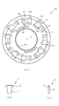
- the first member 50 will be described with reference to FIG. FIG. 2 is a front view of the first member 50.
- FIG. The first member 50 is a substantially annular member provided with the first surface 51.
- the first surface 51 is a flat surface orthogonal to the axis O.
- the first member 50 is coupled to the output shaft 12 by splines 52 extending in the direction of the axis O.
- the first member 50 has an annular groove 53 formed in the first surface 51.
- the first surface 51 has a plurality of (eight in the present embodiment) recesses 54 formed on the groove 53.
- a through hole 55 that penetrates the first member 50 in the thickness direction (the direction of the axis O) is formed on the groove 53 in the recess 54.
- the recess 54 is a portion into which the first engaging element 70 and the second engaging element 80 supported swingably by the second member 60 enter.
- the recesses 54 have openings that are substantially rectangular in a front view, and are formed on the circumference of the groove 53 at substantially equal intervals.
- the radial width of the recess 54 is slightly larger than the widths of the main body 71 of the first engagement element 70 and the main body 81 (both will be described later) of the second engagement element 80.
- the main body portions 71 and 81 can enter the recess 54.
- the groove 53 is a portion that accommodates the ring member 56 (see FIG. 1) movably in the circumferential direction and the axis O direction.
- the groove 53 has a rectangular cross-sectional shape in a cross section including the axis O.
- the through holes 55 are portions where the pins 57 (see FIG. 1) are slidably fitted.
- the pin 57 transmits the force of the transmission mechanism 100 to the ring member 56.
- the ring member 56 regulates the swinging of the first engaging element 70 and the second engaging element 80.
- FIG. 3A is a rear view of the second member 60.
- the second member 60 is a substantially annular member provided with the second surface 61.
- the second surface 61 is a flat surface orthogonal to the axis O.
- the second surface 61 faces the first surface 51 of the first member 50 in the direction of the axis O.
- the second member 60 is coupled to the input shaft 11 by a spline 62 extending in the direction of the axis O.
- the second member 60 is formed with an annular wall portion 63 surrounding the second surface 61 around the second surface 61.
- a restricting member 90 (described later) is disposed on the second surface 61 inside the wall 63.
- a plurality of (in the present embodiment, a total of eight) first recesses 64 and second recesses 65 are formed at positions corresponding to the recesses 54 formed in the first surface 51 (see FIG. 2). Be done.
- the first engaging element 70 and the spring 73 are accommodated in the first recess 64, and the second engaging element 80 and the spring 83 are accommodated in the second recess 65.
- the first recess 64 and the second recess 65 are alternately provided in the circumferential direction of the second surface 61.
- FIG. 3 (b) is a rear view of the first engaging element 70
- FIG. 3 (c) is a side view of the first engaging element 70.
- the first engaging element 70 and the second engaging element 80 are configured the same except that the circumferential direction of the second member 60 is different. Therefore, each part of the 1st engaging element 70 is demonstrated, and description of each part of the 2nd engaging element 80 is abbreviate
- the first engaging element 70 is a plate-like body having a substantially T-shape in a front view, and protrudes from both sides of an end of the main body 71 and the main body 71 formed in a substantially rectangular shape in a front view.
- a substantially rod-like arm portion 72 is provided. The first engaging element 70 and the second engaging element 80 transmit torques in different directions.
- the first concave portion 64 includes a main body accommodating portion 64 a which is a shallow recess in which the main body portion 71 of the first engagement element 70 is accommodated, and an arm accommodating portion 64 b which is a shallow recess in which the arm portion 72 is accommodated.
- the arm accommodating portion 64b is connected to the main body accommodating portion 64a.
- the first concave portion 64 is disposed with the arm accommodating portion 64b facing inward and outward in the radial direction in a state where the main body accommodating portion 64a is arranged in the circumferential direction.
- a spring accommodating portion 64c which is a depression deeper than the main body accommodating portion 64a is connected to the main body accommodating portion 64a on the opposite side to the arm accommodating portion 64b.
- the spring 73 (see FIG. 1) is accommodated in the spring accommodating portion 64c.
- the second recess 65 is provided with a main body accommodating portion 65a which is a shallow recess in which the main body portion 81 of the second engaging element 80 is accommodated, and an arm accommodating portion 65b which is a shallow recess in which the arm portion 82 is accommodated.
- the arm accommodating portion 65b is connected to the main body accommodating portion 65a.
- the second recess 65 is disposed with the arm receiving portion 65b facing inward and outward in the radial direction in a state where the main body receiving portions 65a are arranged in the circumferential direction.
- a spring accommodating portion 65c which is a recess deeper than the main body accommodating portion 65a is connected to the main body accommodating portion 65a on the opposite side to the arm accommodating portion 65b.
- the spring 83 (see FIG. 1) is accommodated in the spring accommodating portion 65c.
- the springs 73 and 83 are torsion coil springs, but the present invention is not limited to this. It is of course possible to use a compression coil spring or the like instead of the torsion coil spring.
- the main body housing portion 65 a and the arm housing portion 65 b of the second recess 65 are disposed at positions facing the main body housing portion 64 a and the arm housing portion 64 b of the first concave portion 64. Further, the length of the main body housing portion 65a and the arm housing portion 65b of the second concave portion 65 in the circumferential direction is set larger than that of the main body housing portion 64a and the arm housing portion 64b of the first concave portion 64.
- a substantially arc-shaped groove 66 extending in the circumferential direction is formed on the radially inner side of the second surface 61.
- the groove portion 66 is a portion where a coil spring 96 (described later) for biasing the regulating member 90 (described later) to one side in the circumferential direction is disposed.
- FIG. 4A is a rear view of the second member 60 in which the first engaging element 70, the second engaging element 80, and the regulating member 90 are assembled
- FIG. 4B is a first engaging element 70 with the second engaging element.
- It is a rear view of the 2nd member 60 which regulation member 90 slid in the 2nd member 60 with which union 80 and regulation member 90 were attached.
- 4A and 4B illustration of the spring accommodating portions 64c and 65c of the first recess 64 and the second recess 65 is omitted for easy understanding.
- the first engaging element 70 and the second engaging element 80 are disposed in the first recess 64 and the second recess 65 formed on the second surface 61, respectively. .
- the first engagement piece 70 and the second engagement piece 80 are respectively pivoted around the arm portions 72 and 82 by springs 73 and 83 (see FIG. 1) accommodated in the first recess 64 and the second recess 65.
- the main housing portion 65a and the arm housing portion 65b of the second concave portion 65 are set to have a circumferential length greater than that of the main body housing portion 64a and the arm housing portion 64b of the first concave portion 64.
- the main body portion 81 and the arm portion 82 can move in the circumferential direction in the main body storage portion 65a and the arm storage portion 65b.
- the regulating member 90 is a plate-like body for regulating the swing of the first engaging element 70, and is disposed between the second surface 61 of the second member 60 and the first surface 51 of the first member 50.
- the restriction member 90 includes an annular portion 91 formed in an annular shape, a plurality of (four in the present embodiment) first convex portions 92 projecting outward in the radial direction from the outer periphery of the annular portion 91, and A plurality of (four in the present embodiment) second convex portions 94 are provided to protrude radially outward from the annular portion 91 between the first convex portions 92.
- the first convex portion 92 is provided with a locking portion 93 which covers the main body portion 71 of the first engaging element 70 accommodated in the first concave portion 64 and restricts the swinging of the first engaging element 70.
- the locking portion 93 bends the outside in the radial direction of the first convex portion 92 located in the same plane as the annular portion 91 to slightly slightly move in the axial direction than the annular portion 91 and the first convex portion 92 (FIG. a) It is formed in a step-like shape so as to be positioned on the front side of the drawing sheet).
- the second convex portion 94 includes an abutting portion 95 with which an end portion on the arm portion 82 side of the second engaging element 80 accommodated in the second concave portion 65 abuts.
- the abutting portion 95 is formed at an end edge of the second convex portion 94 in the circumferential direction.
- the length (outer diameter) of the first protrusion 92 and the second protrusion 94 in the radial direction is set to be smaller than the inner diameter of the ring member 56 (see FIG. 1). This is to prevent interference between the regulating member 90 and the ring member 56.
- a coil spring 96 (see FIG. 6A) is disposed in a groove 66 (see FIG. 3A) formed inward in the radial direction of the second surface 61.
- the annular portion 91 is provided with a projection 97 (see FIG. 6A) that protrudes in the axial direction from the end surface in the axial direction.
- the contact portion 95 of the second projection 94 is the arm of the second engaging element 80.
- the second engaging element 80 is pressed in the circumferential direction by coming into contact with the circumferential end surface of the portion 82.
- the restriction member 90 is stopped.
- the locking portion 93 is placed on the main body portion 71 of the first engaging element 70.
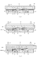
- FIG. 5 is a cross-sectional view of the clutch 10.
- the first engaging element 70 and the spring 73 are accommodated in the first recess 64 (see FIG. 3A) of the second member 60, and in the second recess 65 (see FIG. 3A).
- the second engaging element 80 and the spring 83 are accommodated.
- the ring member 56 is accommodated in the groove 53 (see FIG. 2) of the first member 50.
- the first member 50 and the second member 60 are assembled such that the second surface 61 of the second member 60 faces the first surface 51 of the first member 50.
- the transmission mechanism 100 is a mechanism that transmits the output of the actuator 26 to the meshing clutch 40.
- the actuator 26 and the transmission mechanism 100 constitute a driving device.
- the transmission mechanism 100 includes a ball cam 30 and a pressing member 24, a pin 101 for transmitting the force of the pressing member 24 to the operating member 102, and a spring 103 for biasing the operating member 102 toward the first member 50.
- the pin 101 penetrates the second member 60 and the clutch hub 21 in the direction of the axis O.
- the spring 103 pushes the pin 57 toward the second member 60 via the operation member 102.
- the elastic force in the direction of the axis O of the spring 103 is larger than the elastic force in the direction of the axis O of the springs 73 and 83. Therefore, in a state where the ring member 56 pressed by the pin 57 enters the recess 54, the first engaging element 70 and the second engaging element 80 can not enter into the recess 54.
- the second engaging element 80 can enter into the recess 54 before the clutch plate 23 is engaged and the input shaft 11 and the output shaft 12 are connected and the first member 50 and the second member 60 are synchronized.
- the length of the pin 101, the operation member 102 and the like in the direction of the axis O is set so that the second engaging element 80 can be engaged.
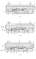
- FIG. 6 (a) is a schematic view of the meshing clutch 40 in a state in which the swinging of the first engagement piece 70 and the second engagement piece 80 is restricted
- FIGS. 6 (b) and 6 (c) are first engagements.
- It is a schematic diagram of the meshing clutch 40 in the state in which rocking
- FIG. 7 (a) is a schematic view of the meshing clutch 40 in which the second engagement piece 80 is engaged with the recess 54
- FIGS. 7 (b) and 7 (c) are a first engagement piece 70 and a second engagement piece.
- FIG. 7 is a schematic view of the meshing clutch 40 when the second member 60 rotates relative to the first member 50 in the forward rotation direction (arrow direction) in a state in which swinging of the coupling 80 is permitted. 6 and 7, parts of the first member 50 and the second member 60 are illustrated in a simplified manner for easy understanding. The lengths of the arrows shown in FIGS. 6 and 7 indicate the level of the rotational speed of the first member 50 and the second member 60 in the forward rotation direction.
- the locking portion 93 is interposed between the first engaging element 70 and the first member 50 by the regulating member 90 biased in the circumferential direction by the coil spring 96,
- the contact portion 95 abuts on the engagement element 80.
- the second engaging element 80 is pressed in the circumferential direction by the contact portion 95, and the arm portion 82 is fixed to the end of the arm storage portion 65b.
- the second engaging element 80 swings. However, when the number of rotations of the second member 60 in the forward direction is higher than the number of rotations of the first member 50, the second engaging element 80 can not engage with the recess 54. Therefore, the torque transmission between the first member 50 and the second member 60 is interrupted.
- the meshing clutch 40 is a two-way clutch in which the first engaging element 70 transmits torque in the forward direction and the second engaging element 80 transmits torque in the reverse direction.
- the actuator 26 is operated to move the pressing member 24.
- the pressing member 24 moves the operation member 102 via the pin 101 while pressing the spring 103.
- the elastic force of the spring 103 acting on the ring member 56 disappears, the second engaging element 80 is advanced into the recess 54 by the spring 83.
- the movement of the pressing member 24 engages the friction clutch 20.
- the friction clutch 20 smoothly transmits torque from the output shaft 12 to which the torque of the motor 15 is input to the input shaft 11 while sliding the clutch plate 23.
- the rotational speed of the first member 50 coupled to the output shaft 12 is higher than the rotational speed of the second member 60 coupled to the input shaft 11.
- the second engagement element 80 engages with the recess 54.
- the second engaging element 80 pushed by the first member 50 pushes the regulating member 90. Since the locking portion 93 interposed between the first engagement piece 70 and the first member 50 is eliminated, the first engagement piece 70 enters the recess 54 by the spring 73. There is almost no shock at this time.
- the second engaging member 70 is used to perform the second Torque is transmitted from the member 60 to the first member 50.
- the actuator 26 is operated to return the pressing member 24 to its original position.
- the vehicle can travel using the engine 14 and the motor 15.
- the motor 15 may be stopped to travel using the engine 14. In that case, power can be generated by the stopped motor 15.
- the elastic force of the spring 103 can not release the engagement of the first engaging element 70, so the pressing member 24 is returned to the original position. Even when the friction clutch 20 is disengaged, the engagement state of the first engaging element 70 is maintained.
- the role of the friction clutch 20 is to synchronize the first member 50 and the second member 60 to engage the first engaging element 70, so that after the first engaging element 70 is engaged, the friction clutch 20 is turned off. It is good. Therefore, the time for applying a load to the clutch plate 23 by the actuator 26 can be shortened. Therefore, the energy consumption of the actuator 26 can be reduced.
- the transmission mechanism 100 applies an elastic force opposite to the moving direction of the pressing member 24 when the spring 103 fastens the friction clutch 20 to the first engaging element 70 and the second engaging element 80, thereby causing the first engagement.
- the coupling 70 and the second engagement element 80 can not be engaged. Therefore, in the state where the friction clutch 20 is connected, the engagement of the first engaging element 70 or the second engaging element 80 with the first member 50 and the second member 60 is permitted. Further, in a state in which the first engagement element 70 or the second engagement element 80 is engaged with the first member 50 and the second member 60, the first engagement element 70 and the second The operation of the engagement element 80 is disabled.
- the engagement state of the first engagement piece 70 and the second engagement piece 80 can be maintained while making the pressing load of the friction clutch 20 unnecessary. As a result, the energy required for the engagement of the friction clutch 20 can be suppressed.
- the engine 14 and the motor 15 are stopped at the time of deceleration or braking in normal traveling.
- the torque in the forward rotation direction is transmitted from the first member 50 coupled to the output shaft 12 to the second member 60 coupled to the input shaft 11 via the second engaging element 80.
- the elastic force of the spring 103 causes the first engaging element 70 and the second engaging element 80 to bite into the recess 54.
- Overcoming the elastic force 73, 83, the operation member 102, the pin 57 and the ring member 56 are pushed toward the second member 60, and the first engagement piece 70 and the second engagement piece 80 are withdrawn from the recess 54.
- a decrease in torque of the output shaft 12 due to the corotation of the input shaft 11 can be prevented, and therefore, it is possible to suppress a loss during power generation by the output shaft 12 of the motor 15.
- the actuator 26 operates the friction clutch 20 and the meshing clutch 40 via the transmission mechanism 100, it is not necessary to provide each of the friction clutch 20 and the meshing clutch 40 with a dedicated actuator. Therefore, the size and weight of the clutch 10 can be reduced by the amount of omission of one of the actuators.
- the present invention has been described above based on the embodiment, the present invention is not limited to the above embodiment, and various improvements and modifications can be made without departing from the scope of the present invention. It can be easily guessed.
- the number and the shape of the first engaging element 70 and the second engaging element 80 are examples, and can be set as appropriate.
- the friction clutch 20 is a disc clutch
- the present invention is not necessarily limited to this, and it is of course possible to adopt other clutches.
- a drum clutch, a conical clutch etc. are mentioned, for example.
- the friction clutch 20 is a wet multi-plate clutch
- the present invention is not necessarily limited thereto, and it is of course possible to adopt a dry clutch, a single plate clutch, a multiple plate clutch, or the like.
- the motor 27 (electric motor) and the friction clutch 20 that operates by operating the ball cam 30 have been described, the present invention is not necessarily limited thereto, and friction clutches such as hydraulic operation, pneumatic operation, electromagnetic operation such as solenoid, etc. It is of course possible to adopt
- the present invention is not necessarily limited thereto, and it is natural to omit the regulating member 90. It is possible.
- the restriction member 90 is omitted, the circumferential length of the second recess 65 is shortened so that the second engaging element 80 can not slide in the second recess 65.
- the said embodiment demonstrated the case where the 1st engaging element 70 and the 2nd engaging element 80 were the same shape, it is not necessarily restricted to this. As a matter of course, it is possible to configure the first engaging element 70 and the second engaging element 80 to have different lengths, widths, and thicknesses.
Abstract
Provided is a clutch with which torque can be transmitted smoothly even when the relative speed and phase difference between an input shaft and an output shaft is large, and energy loss during torque transmission can be reduced. The clutch (10) comprises a dog clutch (40) for transmitting forward-direction and reverse-direction torque from an input shaft (11) to an output shaft (12), and a friction clutch (20) for transmitting torque from the input shaft (11) to the output shaft (12) and provided in parallel with the dog clutch (40), and switching between transmitting/interrupting torque between the input shaft (11) and the output shaft (12) is carried out.
Description
本発明は、入力軸と出力軸との間にトルクを伝達または遮断するクラッチ及び車両の動力伝達構造に関するものである。
TECHNICAL FIELD The present invention relates to a clutch and a power transmission structure of a vehicle that transmits or cuts off torque between an input shaft and an output shaft.
摩擦力によってトルクを伝達する摩擦クラッチが知られている。特許文献1には、エンジンのトルクが入力される入力軸とモータのトルクが入力される出力軸との間に摩擦クラッチを配置した車両の動力伝達構造が開示されている。
A friction clutch that transmits torque by friction is known. Patent Document 1 discloses a power transmission structure of a vehicle in which a friction clutch is disposed between an input shaft to which an engine torque is input and an output shaft to which a motor torque is input.
しかしながら上記従来の技術では、摩擦クラッチの摩擦材に押付荷重を与えて入力軸と出力軸とを同期させるが、入力軸と出力軸とを連結してトルクを伝達するために押付荷重を与え続けなければならないので、押付荷重を与え続けるためのエネルギー損失が生じるという問題点がある。
However, in the above prior art, the pressing load is applied to the friction material of the friction clutch to synchronize the input shaft and the output shaft, but the input shaft and the output shaft are coupled to transmit the torque to transmit the torque. Since it must be done, there is a problem that energy loss occurs to continue applying the pressing load.
一方、機械的かみあいによって係合を行う噛み合いクラッチは、入力軸と出力軸とを同期させることができないという問題点や、同期後に押付荷重は要らないが、入力軸と出力軸との相対速度や位相差が大きいときは、かみあいが難しく、ショックが発生したりトルクを伝達できなかったりするという問題点がある。
On the other hand, the meshing clutch, which engages by mechanical meshing, has a problem that the input shaft and the output shaft can not be synchronized, and no pressing load is required after synchronization, but the relative speed between the input shaft and the output shaft When the phase difference is large, meshing is difficult, and there is a problem that a shock occurs or torque can not be transmitted.
本発明は上述した問題点を解決するためになされたものであり、入力軸と出力軸との相対速度や位相差が大きいときも滑らかにトルクを伝達できると共に、トルクを伝達するときのエネルギー損失を少なくできるクラッチ及び車両の動力伝達構造を提供することを目的としている。
The present invention has been made to solve the above-mentioned problems, and can smoothly transmit torque even when the relative velocity or phase difference between the input shaft and the output shaft is large, as well as the energy loss when transmitting the torque. It is an object of the present invention to provide a clutch and a power transmission structure of a vehicle that can reduce
この目的を達成するために本発明のクラッチは、入力軸と出力軸との間のトルクの伝達と遮断とを切り換えるものであり、入力軸から出力軸へ正転方向および逆転方向のトルクを伝達する噛み合いクラッチと、入力軸から出力軸へトルクを伝達すると共に噛み合いクラッチと並列に設けられる摩擦クラッチと、を備えている。
In order to achieve this object, the clutch of the present invention switches between transmission and disconnection of torque between the input shaft and the output shaft, and transmits torque in the forward and reverse directions from the input shaft to the output shaft. And a friction clutch that transmits torque from the input shaft to the output shaft and is provided in parallel with the meshing clutch.
本発明の車両の動力伝達構造は、本発明のクラッチを備え、入力軸にエンジンのトルクが入力され、出力軸にモータのトルクが入力される。
The power transmission structure of a vehicle according to the present invention comprises the clutch according to the present invention, wherein the torque of the engine is input to the input shaft and the torque of the motor is input to the output shaft.
請求項1記載のクラッチによれば、噛み合いクラッチは、入力軸から出力軸へ正転方向および逆転方向のトルクを伝達する。入力軸から出力軸へトルクを伝達する摩擦クラッチは、噛み合いクラッチと並列に設けられるので、入力軸と出力軸との相対速度や位相差が大きいときも、摩擦クラッチをつないで滑らかにトルクを伝達できる。摩擦クラッチによって入力軸と出力軸とが係合して入力軸と出力軸との相対速度や位相差が小さくなると、噛み合いクラッチを容易につなぐことができる。噛み合いクラッチをつないだ後に摩擦クラッチを切れば、摩擦クラッチの押付荷重は要らなくなる。よって、入力軸と出力軸との相対速度や位相差が大きいときも滑らかにトルクを伝達できると共に、トルクを伝達するときのエネルギー損失を少なくできる。また、摩擦クラッチと噛み合いクラッチとが並列に設けられるので、クラッチの軸方向の寸法が過大にならないようにできる。
According to the clutch of the present invention, the meshing clutch transmits torque in the forward and reverse directions from the input shaft to the output shaft. A friction clutch for transmitting torque from the input shaft to the output shaft is provided in parallel with the meshing clutch, so that the torque is smoothly transmitted by connecting the friction clutch even when the relative speed or phase difference between the input shaft and the output shaft is large. it can. When the input shaft and the output shaft are engaged by the friction clutch and the relative speed or phase difference between the input shaft and the output shaft is reduced, the meshing clutch can be easily engaged. If the friction clutch is disconnected after engaging the meshing clutch, the pressing load of the friction clutch is not required. Therefore, torque can be smoothly transmitted even when the relative velocity or phase difference between the input shaft and the output shaft is large, and energy loss when transmitting torque can be reduced. Further, since the friction clutch and the meshing clutch are provided in parallel, the axial dimension of the clutch can be prevented from being excessive.
請求項2記載のクラッチによれば、噛み合いクラッチは、所定の第1面を有する第1部材が出力軸に結合する。第1面と軸線方向に対向する第2面を有する第2部材が入力軸に結合する。第1面と第2面との間に介在する第1係合子は、第2部材から第1部材への逆転方向のトルクの伝達を遮断すると共に、第1部材と第2部材とを係合して第2部材から第1部材へ正転方向のトルクを伝達する。第1面と第2面との間に介在する第2係合子は、第2部材から第1部材への正転方向のトルクの伝達を遮断すると共に、第1部材と第2部材とを係合して第2部材から第1部材へ逆転方向のトルクを伝達する。
According to the clutch of the second aspect, in the meshing clutch, a first member having a predetermined first surface is coupled to the output shaft. A second member having a second surface axially opposed to the first surface is coupled to the input shaft. A first engagement element interposed between the first surface and the second surface blocks transmission of torque in the reverse direction from the second member to the first member, and engages the first member and the second member. Then, the torque in the forward rotation direction is transmitted from the second member to the first member. A second engagement element interposed between the first surface and the second surface blocks transmission of torque in the normal rotation direction from the second member to the first member, and engages the first member and the second member. The torque in the reverse direction is transmitted from the second member to the first member.
第1係合子および第2係合子は、ばねにより、第1係合子および第2係合子が係合する軸線方向へそれぞれ付勢される。よって、第1係合子または第2係合子は、入力軸と出力軸との相対速度や位相差が小さくなると第1部材および第2部材に係合する。よって、請求項1の効果に加え、噛み合いクラッチを滑らかに係合できる。さらに、噛み合いクラッチの機構を簡略にできるので、軸方向の寸法が過大にならないようにできる。
The first engagement element and the second engagement element are respectively biased by the spring in the axial direction in which the first engagement element and the second engagement element are engaged. Therefore, the first engaging element or the second engaging element engages with the first member and the second member when the relative speed or phase difference between the input shaft and the output shaft decreases. Therefore, in addition to the effect of claim 1, the meshing clutch can be engaged smoothly. Furthermore, since the mechanism of the meshing clutch can be simplified, the axial dimension can be prevented from becoming excessive.
駆動装置は、ばねを弾性変形させて第1係合子および第2係合子を係合不能にするので、第1部材に対して第2部材を空転させることができる。第1係合子および第2係合子を係合不能にするときは、駆動装置は第1係合子または第2係合子を付勢するばねの弾性力に打ち勝つだけで良いので、それに要する駆動装置のエネルギーを少なくできる。
The drive device elastically deforms the spring to make the first engaging element and the second engaging element incapable of engaging with each other, so that the second member can idle relative to the first member. When the first engaging element and the second engaging element can not be engaged, the driving device only needs to overcome the elastic force of the spring that biases the first engaging element or the second engaging element. You can reduce energy.
請求項3記載のクラッチによれば、噛み合いクラッチは、正転方向における第2部材の回転数が第1部材の回転数より高いときに第1係合子を係合不能にしつつ第2係合子を係合可能にする規制部材を備えている。規制部材は、第2係合子が係合した状態で正転方向における第1部材の回転数が第2部材の回転数より高いときに第1係合子を係合可能にする。従って、請求項2の効果に加え、第1係合子が係合した後、第2部材の回転数が第1部材の回転数より高くなると、第1係合子を介して第2部材から第1部材へ正転方向のトルクを伝達できる。
According to the clutch of the third aspect, the meshing clutch makes the second engaging element incapable of engaging the first engaging element when the rotational speed of the second member in the forward direction is higher than that of the first element. A restricting member is provided to be engageable. The restricting member enables engagement of the first engagement element when the rotation speed of the first member in the forward rotation direction is higher than the rotation speed of the second member in a state in which the second engagement element is engaged. Therefore, in addition to the effect of claim 2, when the number of rotations of the second member becomes higher than the number of rotations of the first member after the first engaging element is engaged, the first member The torque in the forward direction can be transmitted to the member.
請求項4記載のクラッチによれば、アクチュエータの出力が、伝達機構により、ばね及び摩擦クラッチへ伝達される。アクチュエータが摩擦クラッチ及び噛み合いクラッチを操作するので、各クラッチ専用のアクチュエータを不要にできる。よって、請求項2又は3の効果に加え、アクチュエータを省略した分だけクラッチを小型化できる。
According to the clutch of claim 4, the output of the actuator is transmitted to the spring and the friction clutch by the transmission mechanism. Since the actuator operates the friction clutch and the meshing clutch, an actuator dedicated to each clutch can be eliminated. Therefore, in addition to the effect of claim 2 or 3, the clutch can be miniaturized by the amount of omission of the actuator.
請求項5記載のクラッチによれば、駆動装置は、第2係合子を係合可能にした後、摩擦クラッチへのアクチュエータの出力の伝達を解除する。その結果、摩擦クラッチを係合する時間が過大にならないようにできるので、請求項4の効果に加え、摩擦クラッチの係合に要するエネルギーを抑制できる。
According to the clutch of the fifth aspect, the drive device releases the transmission of the output of the actuator to the friction clutch after the second engagement element is made engageable. As a result, since the time for engaging the friction clutch can be prevented from becoming excessive, in addition to the effect of claim 4, energy required for engaging the friction clutch can be suppressed.
請求項6記載のクラッチによれば、伝達機構は、第1係合子または第2係合子と第1部材および第2部材とが係合した状態では、摩擦クラッチを切った状態で駆動装置による第1係合子および第2係合子の操作を不能にする。よって、請求項4又は5の効果に加え、摩擦クラッチの押付荷重を不要にしつつ、第1係合子または第2係合子と第1部材および第2部材とが係合した状態を維持できる。
According to the clutch of the sixth aspect, in the state in which the first engaging element or the second engaging element is engaged with the first member and the second member, the transmission mechanism is driven by the driving device with the friction clutch disconnected. (1) Disable the operation of the first engaging element and the second engaging element. Therefore, in addition to the effect of claim 4 or 5, it is possible to maintain the engaged state of the first engaging element or the second engaging element and the first member and the second member while making the pressing load of the friction clutch unnecessary.
請求項7記載の車両の動力伝達構造によれば、請求項1から6のいずれかに記載のクラッチを備え、入力軸にエンジンのトルクが入力され、出力軸にモータのトルクが入力される。入力軸と出力軸との間にクラッチが配置されているので、エンジンやモータを始動したり停止したりしても、トルクの伝達経路の切り換えを滑らかに行うことができる。
According to the power transmission structure of the vehicle of the seventh aspect, the clutch according to any one of the first to sixth aspects is provided, the torque of the engine is input to the input shaft, and the torque of the motor is input to the output shaft. Since the clutch is disposed between the input shaft and the output shaft, switching of the torque transmission path can be smoothly performed even if the engine or motor is started or stopped.
以下、本発明の好ましい実施の形態について添付図面を参照して説明する。まず図1を参照してクラッチ10の概略構成について説明する。図1は本発明の一実施の形態におけるクラッチ10の軸方向断面図である。
Hereinafter, preferred embodiments of the present invention will be described with reference to the attached drawings. The schematic configuration of the clutch 10 will be described first with reference to FIG. FIG. 1 is an axial sectional view of a clutch 10 according to an embodiment of the present invention.
図1に示すようにクラッチ10は、入力軸11の軸線O上に入力軸11に対して回動自在に配置される出力軸12と入力軸11との間のトルクの伝達と遮断とを切り換える装置である。本実施の形態では、変速機(図示せず)を介してエンジン14のトルクが入力軸11に入力され、出力軸12にモータ15(電動機)のトルクが入力される。クラッチ10は、摩擦クラッチ20及び噛み合いクラッチ40を備え、潤滑油が収容されたケース13にそれらが収容されている。
As shown in FIG. 1, the clutch 10 switches between transmission and disconnection of torque between the output shaft 12 and the input shaft 11 which are rotatably arranged on the axis O of the input shaft 11 with respect to the input shaft 11. It is an apparatus. In the present embodiment, the torque of the engine 14 is input to the input shaft 11 via a transmission (not shown), and the torque of the motor 15 (electric motor) is input to the output shaft 12. The clutch 10 includes a friction clutch 20 and a meshing clutch 40, which are accommodated in a case 13 in which a lubricating oil is accommodated.
摩擦クラッチ20は、入力軸11に結合するクラッチハブ21と、出力軸12に結合するクラッチドラム22と、クラッチドラム22とクラッチハブ21との間に配置されたクラッチ板23と、を備えている。本実施の形態では、クラッチハブ21は、噛み合いクラッチ40の第2部材60の外周に結合している。クラッチ板23は、クラッチハブ21及びクラッチドラム22の径方向に重複する部分に配置されており、軸方向に移動可能にクラッチハブ21及びクラッチドラム22に支持されている。
The friction clutch 20 includes a clutch hub 21 coupled to the input shaft 11, a clutch drum 22 coupled to the output shaft 12, and a clutch plate 23 disposed between the clutch drum 22 and the clutch hub 21. . In the present embodiment, the clutch hub 21 is coupled to the outer periphery of the second member 60 of the meshing clutch 40. The clutch plate 23 is disposed at a radially overlapping portion of the clutch hub 21 and the clutch drum 22, and is supported by the clutch hub 21 and the clutch drum 22 so as to be movable in the axial direction.
押付部材24は、クラッチ板23によるクラッチハブ21とクラッチドラム22との締結力を調整する。押付部材24は、クラッチハブ21とクラッチドラム22との間に配置されたばね25により、トルクの伝達を開放する方向へ付勢されている。押付部材24は、アクチュエータ26の駆動により、クラッチ板23を押圧する軸線O方向へ移動してクラッチ板23が伝達するトルクを大きくする。本実施の形態では、摩擦クラッチ20は、係合面が円板形状の湿式多板クラッチ(ディスククラッチ)である。
The pressing member 24 adjusts the fastening force between the clutch hub 21 and the clutch drum 22 by the clutch plate 23. The pressing member 24 is biased by a spring 25 disposed between the clutch hub 21 and the clutch drum 22 in a direction to release the transmission of torque. The pressing member 24 moves in the direction of the axis O pressing the clutch plate 23 by the drive of the actuator 26 to increase the torque transmitted by the clutch plate 23. In the present embodiment, the friction clutch 20 is a wet multi-plate clutch (disc clutch) whose engagement surface is a disc shape.
アクチュエータ26は、モータ27と、モータ27の出力を減速する減速機28とを備えている。減速機28はケース13に固定され、モータ27はブラケット(図示せず)を介してケース13に固定されている。モータ27の回転運動は、ボールカム30により直線運動に変換される。
The actuator 26 includes a motor 27 and a speed reducer 28 that decelerates the output of the motor 27. The reduction gear 28 is fixed to the case 13, and the motor 27 is fixed to the case 13 via a bracket (not shown). The rotational motion of the motor 27 is converted to linear motion by the ball cam 30.
ボールカム30は、クラッチ板23の締結力を無段階に精度良く調整する。ボールカム30は、駆動側の第1プレート31、反力側の第2プレート32及びボール33を備えている。第1プレート31及び第2プレート32は、入力軸11の外周に回転自在に支持されている。第2プレート32は、入力軸11に対する軸方向の移動が規制されており、第1プレート31は、スラスト軸受を介して押付部材24に対面している。第1プレート31の先端は、減速機28の出力軸に接続されたギヤ34と噛み合わされている。第1プレート31及び第2プレート32が互いに対向するカム面には、軸線Oを中心とする同一円周上に所定の位相差を設けた複数の溝が形成されており、カム面にボール33が回転自在に挟持されている。
The ball cam 30 adjusts the fastening force of the clutch plate 23 steplessly and accurately. The ball cam 30 is provided with a first plate 31 on the drive side, a second plate 32 on the reaction side, and a ball 33. The first plate 31 and the second plate 32 are rotatably supported on the outer periphery of the input shaft 11. The second plate 32 is restricted from axial movement with respect to the input shaft 11, and the first plate 31 faces the pressing member 24 via a thrust bearing. The tip of the first plate 31 is engaged with a gear 34 connected to the output shaft of the reduction gear 28. A plurality of grooves provided with a predetermined phase difference on the same circumference centering on the axis O are formed on the cam surface where the first plate 31 and the second plate 32 face each other. Is rotatably held.
摩擦クラッチ20を締結する場合は、減速機28のギヤ34を介して第2プレート32に対して第1プレート31を回転させると、第1プレート31はボール33の押圧を受けながら押付部材24の方向へ移動する。第1プレート31によって押付部材24が軸線O方向へ押されると、押付部材24はクラッチ板23を押す。一方、摩擦クラッチ20の締結を解除する場合は、減速機28のギヤ34を逆方向に回転させることで、押付部材24から離れる方向へ第1プレート31が移動する。第1プレート31が移動した分だけ押付部材24をばね25が第1プレート31側へ押すので、押付部材24はクラッチ板23を押す力を弱める。
When fastening the friction clutch 20, when the first plate 31 is rotated with respect to the second plate 32 through the gear 34 of the reduction gear 28, the first plate 31 receives the pressure of the ball 33 and the pressing member 24 Move in the direction. When the pressing member 24 is pushed in the direction of the axis O by the first plate 31, the pressing member 24 pushes the clutch plate 23. On the other hand, when the engagement of the friction clutch 20 is released, the first plate 31 moves in the direction away from the pressing member 24 by rotating the gear 34 of the reduction gear 28 in the reverse direction. Since the spring 25 pushes the pressing member 24 toward the first plate 31 by the amount of movement of the first plate 31, the pressing member 24 weakens the pressing force of the clutch plate 23.
噛み合いクラッチ40は、出力軸12に結合される第1部材50と、入力軸11に結合される第2部材60と、第1部材50と第2部材60とを係合する第1係合子70及び第2係合子80と、第1部材50及び第2部材60が係合する方向へそれぞれ第1係合子70及び第2係合子80を付勢するばね73,83と、ばね73,83の弾性力に抗して第1係合子70及び第2係合子80を係合不能にする伝達機構100と、を備えている。
The meshing clutch 40 includes a first member 50 coupled to the output shaft 12, a second member 60 coupled to the input shaft 11, and a first engagement member 70 configured to engage the first member 50 and the second member 60. And springs 73 and 83 for biasing the first engaging element 70 and the second engaging element 80 in the direction in which the first and second members 80 and 60 engage, and The transmission mechanism 100 which makes the 1st engaging element 70 and the 2nd engaging element 80 incompetent, resisting elastic force.
図2を参照して第1部材50について説明する。図2は第1部材50の正面図である。第1部材50は第1面51を備える略円環状の部材である。第1面51は、軸線Oと直交する平坦面である。第1部材50は、軸線O方向に延びるスプライン52により出力軸12に結合される。
The first member 50 will be described with reference to FIG. FIG. 2 is a front view of the first member 50. FIG. The first member 50 is a substantially annular member provided with the first surface 51. The first surface 51 is a flat surface orthogonal to the axis O. The first member 50 is coupled to the output shaft 12 by splines 52 extending in the direction of the axis O.
第1部材50は、第1面51に円環状の溝53が形成されている。第1面51は、溝53上に複数(本実施の形態では8個)の凹部54が形成されている。第1部材50は、第1部材50を厚さ方向(軸線O方向)に貫通する貫通孔55が、凹部54内の溝53上に成形されている。
The first member 50 has an annular groove 53 formed in the first surface 51. The first surface 51 has a plurality of (eight in the present embodiment) recesses 54 formed on the groove 53. In the first member 50, a through hole 55 that penetrates the first member 50 in the thickness direction (the direction of the axis O) is formed on the groove 53 in the recess 54.
凹部54は、第2部材60に揺動可能に支持される第1係合子70及び第2係合子80が進入する部位である。凹部54は、正面視が略矩形の開口を有し、溝53の円周上にそれぞれ略均等な間隔で形成されている。凹部54の径方向の幅は、第1係合子70の本体部71及び第2係合子80の本体部81(いずれも後述する)の幅よりわずかに大きい。これにより、本体部71,81は凹部54に進入できる。
The recess 54 is a portion into which the first engaging element 70 and the second engaging element 80 supported swingably by the second member 60 enter. The recesses 54 have openings that are substantially rectangular in a front view, and are formed on the circumference of the groove 53 at substantially equal intervals. The radial width of the recess 54 is slightly larger than the widths of the main body 71 of the first engagement element 70 and the main body 81 (both will be described later) of the second engagement element 80. Thus, the main body portions 71 and 81 can enter the recess 54.
溝53はリング部材56(図1参照)を周方向および軸線O方向に移動可能に収容する部位である。溝53は軸線Oを含む断面において矩形の断面形状を有している。貫通孔55は、ピン57(図1参照)がそれぞれ摺動可能に嵌る部位である。ピン57は、リング部材56に伝達機構100の力を伝達する。リング部材56は第1係合子70及び第2係合子80の揺動を規制する。
The groove 53 is a portion that accommodates the ring member 56 (see FIG. 1) movably in the circumferential direction and the axis O direction. The groove 53 has a rectangular cross-sectional shape in a cross section including the axis O. The through holes 55 are portions where the pins 57 (see FIG. 1) are slidably fitted. The pin 57 transmits the force of the transmission mechanism 100 to the ring member 56. The ring member 56 regulates the swinging of the first engaging element 70 and the second engaging element 80.
図3(a)を参照して第2部材60について説明する。図3(a)は第2部材60の背面図である。第2部材60は第2面61を備える略円環状の部材である。第2面61は、軸線Oと直交する平坦面である。第2面61は、第1部材50の第1面51と軸線O方向に対向する。第2部材60は、軸線O方向に延びるスプライン62により入力軸11に結合される。
The second member 60 will be described with reference to FIG. FIG. 3A is a rear view of the second member 60. FIG. The second member 60 is a substantially annular member provided with the second surface 61. The second surface 61 is a flat surface orthogonal to the axis O. The second surface 61 faces the first surface 51 of the first member 50 in the direction of the axis O. The second member 60 is coupled to the input shaft 11 by a spline 62 extending in the direction of the axis O.
第2部材60は、第2面61の周囲に、第2面61を取り囲む円環状の壁部63が形成されている。壁部63の内側の第2面61に規制部材90(後述する)が配置される。第2面61は、第1面51(図2参照)に形成された凹部54に対応する位置に、複数(本実施の形態では合計8個)の第1凹部64及び第2凹部65が形成される。第1凹部64には第1係合子70及びばね73が収容され、第2凹部65には第2係合子80及びばね83が収容される。第1凹部64及び第2凹部65は、第2面61の円周方向に交互に設けられている。
The second member 60 is formed with an annular wall portion 63 surrounding the second surface 61 around the second surface 61. A restricting member 90 (described later) is disposed on the second surface 61 inside the wall 63. In the second surface 61, a plurality of (in the present embodiment, a total of eight) first recesses 64 and second recesses 65 are formed at positions corresponding to the recesses 54 formed in the first surface 51 (see FIG. 2). Be done. The first engaging element 70 and the spring 73 are accommodated in the first recess 64, and the second engaging element 80 and the spring 83 are accommodated in the second recess 65. The first recess 64 and the second recess 65 are alternately provided in the circumferential direction of the second surface 61.
図3(b)及び図3(c)を参照して第1係合子70及び第2係合子80について説明する。図3(b)は第1係合子70の背面図であり、図3(c)は第1係合子70の側面図である。なお、第1係合子70及び第2係合子80は、第2部材60に配置される周方向の向きが異なる以外は同一に構成されている。よって、第1係合子70の各部を説明して、第2係合子80の各部の説明は省略する。
The first engaging element 70 and the second engaging element 80 will be described with reference to FIGS. 3 (b) and 3 (c). FIG. 3 (b) is a rear view of the first engaging element 70, and FIG. 3 (c) is a side view of the first engaging element 70. The first engaging element 70 and the second engaging element 80 are configured the same except that the circumferential direction of the second member 60 is different. Therefore, each part of the 1st engaging element 70 is demonstrated, and description of each part of the 2nd engaging element 80 is abbreviate | omitted.
第1係合子70は、正面視が略T字状の板状体であり、正面視して略矩形状に形成される本体部71と、本体部71の端部の両側縁から両側に突設される略棒状の腕部72とを備えている。第1係合子70及び第2係合子80は、互いに異なる方向のトルクを伝達する。
The first engaging element 70 is a plate-like body having a substantially T-shape in a front view, and protrudes from both sides of an end of the main body 71 and the main body 71 formed in a substantially rectangular shape in a front view. A substantially rod-like arm portion 72 is provided. The first engaging element 70 and the second engaging element 80 transmit torques in different directions.
図3(a)に戻って説明する。第1凹部64は、第1係合子70の本体部71が収容される浅い窪みである本体収容部64aと、腕部72が収容される浅い窪みである腕収容部64bとを備えている。腕収容部64bは本体収容部64aに連接されている。第1凹部64は、本体収容部64aを円周方向に並べた状態で、腕収容部64bを径方向の内外に向けて配置されている。第1凹部64は、本体収容部64aよりも深い窪みであるばね収容部64cが、腕収容部64bと反対側の本体収容部64aに連接されている。ばね収容部64cにばね73(図1参照)が収容される。
Referring back to FIG. The first concave portion 64 includes a main body accommodating portion 64 a which is a shallow recess in which the main body portion 71 of the first engagement element 70 is accommodated, and an arm accommodating portion 64 b which is a shallow recess in which the arm portion 72 is accommodated. The arm accommodating portion 64b is connected to the main body accommodating portion 64a. The first concave portion 64 is disposed with the arm accommodating portion 64b facing inward and outward in the radial direction in a state where the main body accommodating portion 64a is arranged in the circumferential direction. In the first recess 64, a spring accommodating portion 64c which is a depression deeper than the main body accommodating portion 64a is connected to the main body accommodating portion 64a on the opposite side to the arm accommodating portion 64b. The spring 73 (see FIG. 1) is accommodated in the spring accommodating portion 64c.
第2凹部65は、第2係合子80の本体部81が収容される浅い窪みである本体収容部65aと、腕部82が収容される浅い窪みである腕収容部65bとを備えている。腕収容部65bは本体収容部65aに連接されている。第2凹部65は、本体収容部65aを円周方向に並べた状態で、腕収容部65bを径方向の内外に向けて配置されている。第2凹部65は、本体収容部65aよりも深い窪みであるばね収容部65cが、腕収容部65bと反対側の本体収容部65aに連接されている。ばね収容部65cにばね83(図1参照)が収容される。本実施の形態では、ばね73,83はねじりコイルばねであるが、これに限られるものではない。ねじりコイルばねに代えて、圧縮コイルばね等を用いることは当然可能である。
The second recess 65 is provided with a main body accommodating portion 65a which is a shallow recess in which the main body portion 81 of the second engaging element 80 is accommodated, and an arm accommodating portion 65b which is a shallow recess in which the arm portion 82 is accommodated. The arm accommodating portion 65b is connected to the main body accommodating portion 65a. The second recess 65 is disposed with the arm receiving portion 65b facing inward and outward in the radial direction in a state where the main body receiving portions 65a are arranged in the circumferential direction. In the second recess 65, a spring accommodating portion 65c which is a recess deeper than the main body accommodating portion 65a is connected to the main body accommodating portion 65a on the opposite side to the arm accommodating portion 65b. The spring 83 (see FIG. 1) is accommodated in the spring accommodating portion 65c. In the present embodiment, the springs 73 and 83 are torsion coil springs, but the present invention is not limited to this. It is of course possible to use a compression coil spring or the like instead of the torsion coil spring.
第2凹部65の本体収容部65a及び腕収容部65bは、第1凹部64の本体収容部64a及び腕収容部64bと向き合う位置に配置される。また、第2凹部65の本体収容部65a及び腕収容部65bは、第1凹部64の本体収容部64a及び腕収容部64bよりも周方向の長さが大きく設定されている。
The main body housing portion 65 a and the arm housing portion 65 b of the second recess 65 are disposed at positions facing the main body housing portion 64 a and the arm housing portion 64 b of the first concave portion 64. Further, the length of the main body housing portion 65a and the arm housing portion 65b of the second concave portion 65 in the circumferential direction is set larger than that of the main body housing portion 64a and the arm housing portion 64b of the first concave portion 64.
第2部材60は、円周方向に延びる略円弧状の溝部66が第2面61の径方向内側寄りに形成されている。溝部66は、規制部材90(後述する)を周方向の一方に付勢するコイルばね96(後述する)が配置される部位である。
In the second member 60, a substantially arc-shaped groove 66 extending in the circumferential direction is formed on the radially inner side of the second surface 61. The groove portion 66 is a portion where a coil spring 96 (described later) for biasing the regulating member 90 (described later) to one side in the circumferential direction is disposed.
図4を参照して規制部材90について説明する。図4(a)は第1係合子70、第2係合子80及び規制部材90が組み付けられた第2部材60の背面図であり、図4(b)は第1係合子70、第2係合子80及び規制部材90が組み付けられた第2部材60において、規制部材90がスライドした第2部材60の背面図である。なお、図4(a)及び図4(b)では理解を容易にするため、第1凹部64及び第2凹部65のばね収容部64c,65cの図示を省略する。
The regulating member 90 will be described with reference to FIG. FIG. 4A is a rear view of the second member 60 in which the first engaging element 70, the second engaging element 80, and the regulating member 90 are assembled, and FIG. 4B is a first engaging element 70 with the second engaging element. It is a rear view of the 2nd member 60 which regulation member 90 slid in the 2nd member 60 with which union 80 and regulation member 90 were attached. 4A and 4B, illustration of the spring accommodating portions 64c and 65c of the first recess 64 and the second recess 65 is omitted for easy understanding.
図4(a)に示すように第2部材60は、第2面61に形成された第1凹部64及び第2凹部65に、それぞれ第1係合子70及び第2係合子80が配置される。第1係合子70及び第2係合子80は、第1凹部64及び第2凹部65に収容されたばね73,83(図1参照)により、腕部72,82を中心にそれぞれ揺動する。第2凹部65の本体収容部65a及び腕収容部65bは、第1凹部64の本体収容部64a及び腕収容部64bよりも周方向の長さが大きく設定されているので、第2係合子80の本体部81及び腕部82は、本体収容部65a及び腕収容部65b内を周方向に移動できる。
As shown in FIG. 4A, in the second member 60, the first engaging element 70 and the second engaging element 80 are disposed in the first recess 64 and the second recess 65 formed on the second surface 61, respectively. . The first engagement piece 70 and the second engagement piece 80 are respectively pivoted around the arm portions 72 and 82 by springs 73 and 83 (see FIG. 1) accommodated in the first recess 64 and the second recess 65. The main housing portion 65a and the arm housing portion 65b of the second concave portion 65 are set to have a circumferential length greater than that of the main body housing portion 64a and the arm housing portion 64b of the first concave portion 64. The main body portion 81 and the arm portion 82 can move in the circumferential direction in the main body storage portion 65a and the arm storage portion 65b.
規制部材90は、第1係合子70の揺動を規制するための板状体であり、第2部材60の第2面61と第1部材50の第1面51との間に配置される。規制部材90は、円環状に形成された円環部91と、円環部91の外周から径方向の外側に突出する複数(本実施の形態では4つ)の第1凸部92と、第1凸部92間の円環部91から径方向の外側に突出する複数(本実施の形態では4つ)の第2凸部94とを備えている。
The regulating member 90 is a plate-like body for regulating the swing of the first engaging element 70, and is disposed between the second surface 61 of the second member 60 and the first surface 51 of the first member 50. . The restriction member 90 includes an annular portion 91 formed in an annular shape, a plurality of (four in the present embodiment) first convex portions 92 projecting outward in the radial direction from the outer periphery of the annular portion 91, and A plurality of (four in the present embodiment) second convex portions 94 are provided to protrude radially outward from the annular portion 91 between the first convex portions 92.
第1凸部92は、第1凹部64に収容された第1係合子70の本体部71に被さって第1係合子70の揺動を規制する係止部93を備えている。係止部93は、円環部91と同一面内に位置する第1凸部92の径方向の外側を折り曲げて、円環部91及び第1凸部92よりわずかに軸線方向(図4(a)紙面手前側)に位置するように段差状に形成されている。第2凸部94は、第2凹部65に収容された第2係合子80の腕部82側の端部が当接される当接部95を備えている。当接部95は第2凸部94の周方向の端縁に形成されている。
The first convex portion 92 is provided with a locking portion 93 which covers the main body portion 71 of the first engaging element 70 accommodated in the first concave portion 64 and restricts the swinging of the first engaging element 70. The locking portion 93 bends the outside in the radial direction of the first convex portion 92 located in the same plane as the annular portion 91 to slightly slightly move in the axial direction than the annular portion 91 and the first convex portion 92 (FIG. a) It is formed in a step-like shape so as to be positioned on the front side of the drawing sheet). The second convex portion 94 includes an abutting portion 95 with which an end portion on the arm portion 82 side of the second engaging element 80 accommodated in the second concave portion 65 abuts. The abutting portion 95 is formed at an end edge of the second convex portion 94 in the circumferential direction.
なお、規制部材90は、第1凸部92及び第2凸部94の径方向の長さ(外径)が、リング部材56(図1参照)の内径より小さく設定される。規制部材90とリング部材56とが干渉することを防ぐためである。
The length (outer diameter) of the first protrusion 92 and the second protrusion 94 in the radial direction is set to be smaller than the inner diameter of the ring member 56 (see FIG. 1). This is to prevent interference between the regulating member 90 and the ring member 56.
第2部材60には、第2面61の径方向の内側寄りに形成された溝部66(図3(a)参照)にコイルばね96(図6(a)参照)が配置される。円環部91には、軸方向の端面から軸方向に突出する突起部97(図6(a)参照)が設けられている。突起部97が、コイルばね96によって周方向の一方側(図4(a)時計回り)に向けて押圧されることにより、第2凸部94の当接部95が第2係合子80の腕部82の周方向端面に当接され、第2係合子80が周方向に押圧される。押圧された第2係合子80が第2凹部65の周方向端部に突き当たる位置で、規制部材90は停止する。このとき、第1係合子70の本体部71に係止部93が被さった状態となる。
In the second member 60, a coil spring 96 (see FIG. 6A) is disposed in a groove 66 (see FIG. 3A) formed inward in the radial direction of the second surface 61. As shown in FIG. The annular portion 91 is provided with a projection 97 (see FIG. 6A) that protrudes in the axial direction from the end surface in the axial direction. When the projection 97 is pressed by the coil spring 96 toward one side in the circumferential direction (clockwise in FIG. 4A), the contact portion 95 of the second projection 94 is the arm of the second engaging element 80. The second engaging element 80 is pressed in the circumferential direction by coming into contact with the circumferential end surface of the portion 82. At a position where the pressed second engagement element 80 abuts on the circumferential end of the second recess 65, the restriction member 90 is stopped. At this time, the locking portion 93 is placed on the main body portion 71 of the first engaging element 70.
図4(b)に示すように、周方向の他方側(図4(b)反時計回り)に向けて第2係合子80に荷重を付与すると、第2係合子80に当接する当接部95が第2係合子80に押圧される。その荷重がコイルばね96(図6(a)参照)の付勢力より大きい場合には、第2凹部65内を第2係合子80がスライドして、規制部材90が周方向の他方側(図4(b)反時計回り)に回転する。係止部93の位置が周方向の他方側(図4(b)反時計回り)にずれるので、第1係合子70は係止部93から開放される。
As shown in FIG. 4 (b), when a load is applied to the second engaging element 80 toward the other side in the circumferential direction (counterclockwise in FIG. 4 (b)), the contact portion that contacts the second engaging element 80. 95 is pressed by the second engaging element 80. When the load is larger than the biasing force of the coil spring 96 (see FIG. 6A), the second engaging element 80 slides in the second recess 65, and the regulating member 90 is on the other side in the circumferential direction (see FIG. 4 (b) turn counterclockwise). Since the position of the locking portion 93 is shifted to the other side in the circumferential direction (counterclockwise in FIG. 4 (b)), the first engagement element 70 is released from the locking portion 93.
図1及び図5を参照して噛み合いクラッチ40についてさらに説明する。図5はクラッチ10の断面図である。図1に示すように、第2部材60の第1凹部64(図3(a)参照)に第1係合子70及びばね73が収容され、第2凹部65(図3(a)参照)に第2係合子80及びばね83が収容される。一方、第1部材50の溝53(図2参照)にリング部材56が収容される。第2部材60の第2面61が第1部材50の第1面51と対面するように、第1部材50及び第2部材60が組み付けられる。
The meshing clutch 40 will be further described with reference to FIGS. 1 and 5. FIG. 5 is a cross-sectional view of the clutch 10. As shown in FIG. 1, the first engaging element 70 and the spring 73 are accommodated in the first recess 64 (see FIG. 3A) of the second member 60, and in the second recess 65 (see FIG. 3A). The second engaging element 80 and the spring 83 are accommodated. On the other hand, the ring member 56 is accommodated in the groove 53 (see FIG. 2) of the first member 50. The first member 50 and the second member 60 are assembled such that the second surface 61 of the second member 60 faces the first surface 51 of the first member 50.
伝達機構100は、アクチュエータ26の出力を噛み合いクラッチ40へ伝達する機構である。アクチュエータ26及び伝達機構100は駆動装置を構成する。伝達機構100は、ボールカム30及び押付部材24と、押付部材24の力を操作部材102に伝達するピン101と、操作部材102を第1部材50側へ付勢するばね103とを備えている。ピン101は、第2部材60及びクラッチハブ21を軸線O方向に貫通する。ばね103は操作部材102を介してピン57を第2部材60側へ押し込む。ばね103の軸線O方向の弾性力は、ばね73,83の軸線O方向の弾性力よりも大きいので、ピン57に押されたリング部材56が凹部54内へ進入した状態では、第1係合子70及び第2係合子80は凹部54内へ進入できない。
The transmission mechanism 100 is a mechanism that transmits the output of the actuator 26 to the meshing clutch 40. The actuator 26 and the transmission mechanism 100 constitute a driving device. The transmission mechanism 100 includes a ball cam 30 and a pressing member 24, a pin 101 for transmitting the force of the pressing member 24 to the operating member 102, and a spring 103 for biasing the operating member 102 toward the first member 50. The pin 101 penetrates the second member 60 and the clutch hub 21 in the direction of the axis O. The spring 103 pushes the pin 57 toward the second member 60 via the operation member 102. The elastic force in the direction of the axis O of the spring 103 is larger than the elastic force in the direction of the axis O of the springs 73 and 83. Therefore, in a state where the ring member 56 pressed by the pin 57 enters the recess 54, the first engaging element 70 and the second engaging element 80 can not enter into the recess 54.
これに対し、図5に示すようにアクチュエータ26を作動してボールカム30の第1プレート31を押付部材24側へ移動させると、押付部材24は、クラッチ板23を締結して入力軸11と出力軸12とを連結できる。また、押付部材24は、ばね103を押し込みながらピン101を介して操作部材102を移動させる。これにより、リング部材56に作用するばね103の弾性力がなくなるので、第1係合子70及び第2係合子80は、ばね73,83によって凹部54内へ進入できるようになる。
On the other hand, as shown in FIG. 5, when the actuator 26 is operated to move the first plate 31 of the ball cam 30 to the pressing member 24 side, the pressing member 24 fastens the clutch plate 23 to output the input shaft 11 and the output. The shaft 12 can be connected. Further, the pressing member 24 moves the operation member 102 via the pin 101 while pushing the spring 103. As a result, since the elastic force of the spring 103 acting on the ring member 56 is eliminated, the first engaging element 70 and the second engaging element 80 can enter into the recess 54 by the springs 73 and 83.
なお、クラッチ板23を締結し、入力軸11と出力軸12とを連結して第1部材50と第2部材60とが同期する前に、第2係合子80が凹部54内へ進入できるように(第2係合子80が係合可能となるように)、ピン101や操作部材102等は軸線O方向の長さが設定されている。
The second engaging element 80 can enter into the recess 54 before the clutch plate 23 is engaged and the input shaft 11 and the output shaft 12 are connected and the first member 50 and the second member 60 are synchronized. The length of the pin 101, the operation member 102 and the like in the direction of the axis O is set so that the second engaging element 80 can be engaged.
次に図6及び図7を参照して、噛み合いクラッチ40の動作について説明する。図6(a)は第1係合子70及び第2係合子80の揺動が規制された状態の噛み合いクラッチ40の模式図であり、図6(b)及び図6(c)は第1係合子70及び第2係合子80の揺動が許容された状態の噛み合いクラッチ40の模式図である。
Next, the operation of the meshing clutch 40 will be described with reference to FIGS. 6 and 7. FIG. 6 (a) is a schematic view of the meshing clutch 40 in a state in which the swinging of the first engagement piece 70 and the second engagement piece 80 is restricted, and FIGS. 6 (b) and 6 (c) are first engagements. It is a schematic diagram of the meshing clutch 40 in the state in which rocking | fluctuation of the coupling 70 and the 2nd engaging element 80 was permitted.
また、図7(a)は第2係合子80が凹部54に係合した噛み合いクラッチ40の模式図であり、図7(b)及び図7(c)は第1係合子70及び第2係合子80の揺動が許容された状態で第1部材50に対して第2部材60が正転方向(矢印方向)へ相対回転するときの噛み合いクラッチ40の模式図である。なお、図6及び図7では、理解を容易にするために第1部材50及び第2部材60の一部を簡略化して図示する。図6及び図7に示す矢印の長さは、正転方向における第1部材50及び第2部材60の回転数の高低を表している。
7 (a) is a schematic view of the meshing clutch 40 in which the second engagement piece 80 is engaged with the recess 54, and FIGS. 7 (b) and 7 (c) are a first engagement piece 70 and a second engagement piece. FIG. 7 is a schematic view of the meshing clutch 40 when the second member 60 rotates relative to the first member 50 in the forward rotation direction (arrow direction) in a state in which swinging of the coupling 80 is permitted. 6 and 7, parts of the first member 50 and the second member 60 are illustrated in a simplified manner for easy understanding. The lengths of the arrows shown in FIGS. 6 and 7 indicate the level of the rotational speed of the first member 50 and the second member 60 in the forward rotation direction.
図6(a)に示すように、コイルばね96によって周方向へ付勢された規制部材90により、第1係合子70と第1部材50との間に係止部93が介在し、第2係合子80に当接部95が当接する。第2係合子80は当接部95により周方向へ押圧されて、腕収容部65bの端部に腕部82が固定される。リング部材56が第1部材50の凹部54に進入した状態では、第1係合子70及び第2係合子80は凹部54へ進入して係合できないので、第1部材50と第2部材60との間のトルク伝達は遮断される。
As shown in FIG. 6A, the locking portion 93 is interposed between the first engaging element 70 and the first member 50 by the regulating member 90 biased in the circumferential direction by the coil spring 96, The contact portion 95 abuts on the engagement element 80. The second engaging element 80 is pressed in the circumferential direction by the contact portion 95, and the arm portion 82 is fixed to the end of the arm storage portion 65b. When the ring member 56 enters the recess 54 of the first member 50, the first engaging element 70 and the second engaging element 80 can not enter the recess 54 and can not be engaged, and thus the first member 50 and the second member 60 The torque transfer between them is interrupted.
図6(b)及び図6(c)に示すように、リング部材56が第1部材50の凹部54から退出した状態では、第2係合子80は揺動する。しかし、正転方向における第2部材60の回転数が第1部材50の回転数より高いときは、第2係合子80は凹部54に係合できない。よって、第1部材50と第2部材60との間のトルク伝達は遮断される。
As shown in FIGS. 6B and 6C, in a state in which the ring member 56 is withdrawn from the recess 54 of the first member 50, the second engaging element 80 swings. However, when the number of rotations of the second member 60 in the forward direction is higher than the number of rotations of the first member 50, the second engaging element 80 can not engage with the recess 54. Therefore, the torque transmission between the first member 50 and the second member 60 is interrupted.
図7(a)に示すように、正転方向における第1部材50の回転数が第2部材60の回転数より高いときは、凹部54に進入した第2係合子80が周方向に押されると、コイルばね96を押し込みながら、当接部95によって規制部材90が周方向に押される。係止部93が第1係合子70を開放すると、図7(c)に示すように第1係合子70が凹部54へ進入して係合する。第2部材60が正転方向に駆動すると、第1係合子70を介して第1部材50が被動し、第2部材60から第1部材50へトルクが伝達される。
As shown in FIG. 7A, when the number of rotations of the first member 50 in the forward direction is higher than the number of rotations of the second member 60, the second engaging element 80 entering the recess 54 is pushed in the circumferential direction The regulating member 90 is pushed in the circumferential direction by the contact portion 95 while pushing the coil spring 96. When the locking portion 93 releases the first engaging element 70, the first engaging element 70 enters the recess 54 and engages as shown in FIG. 7C. When the second member 60 is driven in the normal direction, the first member 50 is moved via the first engaging element 70, and torque is transmitted from the second member 60 to the first member 50.
なお、リング部材56を凹部54内に進入させることにより、凹部54に進入した第1係合子70及び第2係合子80を凹部54から退出させ、第1部材50と第2部材60との間の動力伝達を遮断できる。噛み合いクラッチ40は、正転方向のトルクを第1係合子70が伝達し、逆転方向のトルクを第2係合子80が伝達する二方向クラッチである。
When the ring member 56 is advanced into the recess 54, the first engaging element 70 and the second engaging element 80 entering the recess 54 are withdrawn from the recess 54, and between the first member 50 and the second member 60. Power transmission can be shut off. The meshing clutch 40 is a two-way clutch in which the first engaging element 70 transmits torque in the forward direction and the second engaging element 80 transmits torque in the reverse direction.
次に図1及び図5を参照して、クラッチ10の入力軸11にエンジン14のトルクが入力され、出力軸12にモータ15のトルクが入力される車両の動力伝達構造におけるクラッチ10の動作の一例を説明する。
1 and 5, the torque of engine 14 is input to input shaft 11 of clutch 10, and the torque of motor 15 is input to output shaft 12 of the operation of clutch 10 in the power transmission structure of the vehicle. An example will be described.
車両の発進時および低中速走行ではエンジン14を停止し、図1に示すようにクラッチ10の摩擦クラッチ20及び噛み合いクラッチ40を切る。これにより、車両はモータ15を使って発進し走行する。
When starting the vehicle and traveling at low and medium speeds, the engine 14 is stopped, and as shown in FIG. 1, the friction clutch 20 and the meshing clutch 40 of the clutch 10 are disengaged. Thus, the vehicle starts using the motor 15 and travels.
通常走行のときは、モータ15のトルクを出力軸12に入力した状態で、図5に示すようにアクチュエータ26を作動して押付部材24を移動させる。押付部材24は、ばね103を押し込みながらピン101を介して操作部材102を移動させる。その結果、リング部材56に作用するばね103の弾性力がなくなるので、第2係合子80は、ばね83によって凹部54内へ進入する。
During normal travel, with the torque of the motor 15 being input to the output shaft 12, as shown in FIG. 5, the actuator 26 is operated to move the pressing member 24. The pressing member 24 moves the operation member 102 via the pin 101 while pressing the spring 103. As a result, since the elastic force of the spring 103 acting on the ring member 56 disappears, the second engaging element 80 is advanced into the recess 54 by the spring 83.
押付部材24が移動することによって摩擦クラッチ20が係合する。摩擦クラッチ20はクラッチ板23を滑らせながら、モータ15のトルクが入力される出力軸12から入力軸11へ滑らかにトルクを伝達する。摩擦クラッチ20が滑り状態にあるときは、出力軸12に結合した第1部材50の回転数は、入力軸11に結合した第2部材60の回転数より高い。よって、第2係合子80は凹部54に係合する。第1部材50に押された第2係合子80は、規制部材90を押す。第1係合子70と第1部材50との間に介在する係止部93がなくなるので、第1係合子70は、ばね73によって凹部54内へ進入する。このときにショックはほとんど生じない。
The movement of the pressing member 24 engages the friction clutch 20. The friction clutch 20 smoothly transmits torque from the output shaft 12 to which the torque of the motor 15 is input to the input shaft 11 while sliding the clutch plate 23. When the friction clutch 20 is in a sliding state, the rotational speed of the first member 50 coupled to the output shaft 12 is higher than the rotational speed of the second member 60 coupled to the input shaft 11. Thus, the second engagement element 80 engages with the recess 54. The second engaging element 80 pushed by the first member 50 pushes the regulating member 90. Since the locking portion 93 interposed between the first engagement piece 70 and the first member 50 is eliminated, the first engagement piece 70 enters the recess 54 by the spring 73. There is almost no shock at this time.
次に、エンジン14のトルクが入力軸11へ伝達され、入力軸11に結合する第2部材60の回転数が第1部材50の回転数より高くなると、第1係合子70を介して第2部材60から第1部材50へトルクが伝達される。次いで、摩擦クラッチ20を切るために、アクチュエータ26を作動して押付部材24を元の位置へ戻す。これにより、車両はエンジン14及びモータ15を使って走行できる。なお、モータ15を停止して、エンジン14を使って走行しても良い。その場合には、停止したモータ15により発電できる。
Next, when the torque of the engine 14 is transmitted to the input shaft 11 and the rotation speed of the second member 60 coupled to the input shaft 11 becomes higher than the rotation speed of the first member 50, the second engaging member 70 is used to perform the second Torque is transmitted from the member 60 to the first member 50. Then, in order to disengage the friction clutch 20, the actuator 26 is operated to return the pressing member 24 to its original position. Thus, the vehicle can travel using the engine 14 and the motor 15. Alternatively, the motor 15 may be stopped to travel using the engine 14. In that case, power can be generated by the stopped motor 15.
第2部材60が駆動して第1係合子70がトルクを伝達する間は、ばね103の弾性力では第1係合子70の係合を解除できないので、押付部材24を元の位置へ戻して摩擦クラッチ20を切っても第1係合子70の係合状態が維持される。摩擦クラッチ20の役割は、第1部材50と第2部材60とを同期して第1係合子70を係合させることなので、第1係合子70が係合した後は、摩擦クラッチ20を切っても良い。従って、アクチュエータ26によってクラッチ板23に荷重を付与する時間を短くできる。よって、アクチュエータ26の消費エネルギーを少なくできる。
While the second member 60 is driven and the first engaging element 70 transmits torque, the elastic force of the spring 103 can not release the engagement of the first engaging element 70, so the pressing member 24 is returned to the original position. Even when the friction clutch 20 is disengaged, the engagement state of the first engaging element 70 is maintained. The role of the friction clutch 20 is to synchronize the first member 50 and the second member 60 to engage the first engaging element 70, so that after the first engaging element 70 is engaged, the friction clutch 20 is turned off. It is good. Therefore, the time for applying a load to the clutch plate 23 by the actuator 26 can be shortened. Therefore, the energy consumption of the actuator 26 can be reduced.
伝達機構100は、ばね103が、摩擦クラッチ20を締結するときの押付部材24の移動方向とは逆向きの弾性力を第1係合子70及び第2係合子80に付与して、第1係合子70及び第2係合子80を係合不能にする。従って、摩擦クラッチ20をつないだ状態では、第1係合子70又は第2係合子80と第1部材50及び第2部材60との係合を許容する。また、第1係合子70又は第2係合子80と第1部材50及び第2部材60とが係合した状態では、摩擦クラッチ20を切った状態でアクチュエータ26による第1係合子70及び第2係合子80の操作を不能にする。よって、第1係合子70や第2係合子80が係合したときは、摩擦クラッチ20の押付荷重を不要にしつつ、第1係合子70や第2係合子80の係合状態を維持できる。その結果、摩擦クラッチ20の係合に要するエネルギーを抑制できる。
The transmission mechanism 100 applies an elastic force opposite to the moving direction of the pressing member 24 when the spring 103 fastens the friction clutch 20 to the first engaging element 70 and the second engaging element 80, thereby causing the first engagement. The coupling 70 and the second engagement element 80 can not be engaged. Therefore, in the state where the friction clutch 20 is connected, the engagement of the first engaging element 70 or the second engaging element 80 with the first member 50 and the second member 60 is permitted. Further, in a state in which the first engagement element 70 or the second engagement element 80 is engaged with the first member 50 and the second member 60, the first engagement element 70 and the second The operation of the engagement element 80 is disabled. Therefore, when the first engagement piece 70 and the second engagement piece 80 are engaged, the engagement state of the first engagement piece 70 and the second engagement piece 80 can be maintained while making the pressing load of the friction clutch 20 unnecessary. As a result, the energy required for the engagement of the friction clutch 20 can be suppressed.
通常走行において減速や制動のときは、エンジン14及びモータ15を停止する。出力軸12に結合する第1部材50から、第2係合子80を介して、入力軸11に結合する第2部材60へ正転方向のトルクが伝わる。第1部材50の回転数と第2部材60の回転数とが略等しくなると、ばね103の弾性力が、第1係合子70及び第2係合子80が凹部54に噛み込む力、並びに、ばね73,83の弾性力に打ち勝ち、操作部材102、ピン57及びリング部材56が第2部材60側へ押され、第1係合子70及び第2係合子80が凹部54から退出する。これにより、入力軸11の連れ回りによる出力軸12のトルクの低下を防止できるので、モータ15の出力軸12による発電時の損失を抑制できる。
The engine 14 and the motor 15 are stopped at the time of deceleration or braking in normal traveling. The torque in the forward rotation direction is transmitted from the first member 50 coupled to the output shaft 12 to the second member 60 coupled to the input shaft 11 via the second engaging element 80. When the number of rotations of the first member 50 and the number of rotations of the second member 60 become substantially equal, the elastic force of the spring 103 causes the first engaging element 70 and the second engaging element 80 to bite into the recess 54. Overcoming the elastic force 73, 83, the operation member 102, the pin 57 and the ring member 56 are pushed toward the second member 60, and the first engagement piece 70 and the second engagement piece 80 are withdrawn from the recess 54. As a result, a decrease in torque of the output shaft 12 due to the corotation of the input shaft 11 can be prevented, and therefore, it is possible to suppress a loss during power generation by the output shaft 12 of the motor 15.
クラッチ10は、アクチュエータ26が伝達機構100を介して摩擦クラッチ20及び噛み合いクラッチ40を操作するので、摩擦クラッチ20及び噛み合いクラッチ40の各々に専用のアクチュエータを設けなくても良い。従って、片方のアクチュエータを省略した分だけクラッチ10を小型化・軽量化できる。
In the clutch 10, since the actuator 26 operates the friction clutch 20 and the meshing clutch 40 via the transmission mechanism 100, it is not necessary to provide each of the friction clutch 20 and the meshing clutch 40 with a dedicated actuator. Therefore, the size and weight of the clutch 10 can be reduced by the amount of omission of one of the actuators.
以上、実施の形態に基づき本発明を説明したが、本発明は上記実施の形態に何ら限定されるものではなく、本発明の趣旨を逸脱しない範囲内で種々の改良変形が可能であることは容易に推察できるものである。例えば、第1係合子70及び第2係合子80の数や形状は例示であり、適宜設定できる。
Although the present invention has been described above based on the embodiment, the present invention is not limited to the above embodiment, and various improvements and modifications can be made without departing from the scope of the present invention. It can be easily guessed. For example, the number and the shape of the first engaging element 70 and the second engaging element 80 are examples, and can be set as appropriate.
上記実施の形態では、摩擦クラッチ20がディスククラッチの場合について説明したが、必ずしもこれに限られるものではなく、他のクラッチを採用することは当然可能である。他のクラッチとしては、例えばドラムクラッチ、円すいクラッチ等が挙げられる。また、摩擦クラッチ20が湿式多板クラッチの場合について説明したが、必ずしもこれに限られるものではなく、乾式クラッチ、単板クラッチ、複板クラッチ等を採用することは当然可能である。また、モータ27(電動機)及びボールカム30を作動して機能を発揮する摩擦クラッチ20について説明したが、必ずしもこれに限られるものではなく、油圧作動、空気圧作動、ソレノイド等の電磁作動などの摩擦クラッチを採用することは当然可能である。
In the above embodiment, although the case where the friction clutch 20 is a disc clutch has been described, the present invention is not necessarily limited to this, and it is of course possible to adopt other clutches. As another clutch, a drum clutch, a conical clutch etc. are mentioned, for example. Although the case where the friction clutch 20 is a wet multi-plate clutch has been described, the present invention is not necessarily limited thereto, and it is of course possible to adopt a dry clutch, a single plate clutch, a multiple plate clutch, or the like. In addition, although the motor 27 (electric motor) and the friction clutch 20 that operates by operating the ball cam 30 have been described, the present invention is not necessarily limited thereto, and friction clutches such as hydraulic operation, pneumatic operation, electromagnetic operation such as solenoid, etc. It is of course possible to adopt
上記実施の形態では、第1係合子70の揺動を規制する規制部材90が配置された噛み合いクラッチ40について説明したが、必ずしもこれに限られるものではなく、規制部材90を省略することは当然可能である。規制部材90を省略する場合には、第2係合子80が第2凹部65内をスライドできないように、第2凹部65の周方向の長さを短くする。
In the above embodiment, although the meshing clutch 40 in which the regulating member 90 for regulating the swinging of the first engaging element 70 is disposed has been described, the present invention is not necessarily limited thereto, and it is natural to omit the regulating member 90. It is possible. When the restriction member 90 is omitted, the circumferential length of the second recess 65 is shortened so that the second engaging element 80 can not slide in the second recess 65.
上記実施の形態では、リング部材56を介して第1係合子70及び第2係合子80を軸線O方向に押圧する場合について説明したが、必ずしもこれに限られるものではない。リング部材56を省略し、ピン57の先端形状や第1係合子70及び第2係合子80の形状を変更することで、ピン57を介して第1係合子70及び第2係合子80を軸線O方向に押圧することは当然可能である。
Although the case where the 1st engaging element 70 and the 2nd engaging element 80 were pressed in the direction of the axis O via the ring member 56 was demonstrated in the said embodiment, it is not necessarily restricted to this. By omitting the ring member 56 and changing the shape of the tip of the pin 57 and the shapes of the first engaging element 70 and the second engaging element 80, the first engaging element 70 and the second engaging element 80 can be axially aligned via the pin 57. Naturally, it is possible to press in the O direction.
上記実施の形態では、第1係合子70及び第2係合子80が同一形状の場合について説明したが、必ずしもこれに限られるものではない。第1係合子70及び第2係合子80の長さ、幅、厚さが互いに異なるように構成することは当然可能である。
Although the said embodiment demonstrated the case where the 1st engaging element 70 and the 2nd engaging element 80 were the same shape, it is not necessarily restricted to this. As a matter of course, it is possible to configure the first engaging element 70 and the second engaging element 80 to have different lengths, widths, and thicknesses.
10 クラッチ
11 入力軸
12 出力軸
14 エンジン
15 モータ
20 摩擦クラッチ
24 押付部材(伝達機構の一部)
26 アクチュエータ(駆動装置の一部)
30 ボールカム(伝達機構の一部)
40 噛み合いクラッチ
50 第1部材
51 第1面
60 第2部材
61 第2面
70 第1係合子
73 ばね
80 第2係合子
83 ばね
90 規制部材
100 伝達機構(駆動装置の一部)
O 軸線Reference Signs List 10 clutch 11 input shaft 12 output shaft 14 engine 15 motor 20 friction clutch 24 pressing member (part of transmission mechanism)
26 Actuator (part of drive unit)
30 Ball cam (part of transmission mechanism)
40 meshingclutch 50 first member 51 first surface 60 second member 61 second surface 70 first engagement member 73 spring 80 second engagement member 83 spring 90 restriction member 100 transmission mechanism (part of drive unit)
O axis
11 入力軸
12 出力軸
14 エンジン
15 モータ
20 摩擦クラッチ
24 押付部材(伝達機構の一部)
26 アクチュエータ(駆動装置の一部)
30 ボールカム(伝達機構の一部)
40 噛み合いクラッチ
50 第1部材
51 第1面
60 第2部材
61 第2面
70 第1係合子
73 ばね
80 第2係合子
83 ばね
90 規制部材
100 伝達機構(駆動装置の一部)
O 軸線
26 Actuator (part of drive unit)
30 Ball cam (part of transmission mechanism)
40 meshing
O axis
Claims (7)
- 入力軸と出力軸との間のトルクの伝達と遮断とを切り換えるクラッチであって、
前記入力軸から前記出力軸へ正転方向および逆転方向のトルクを伝達する噛み合いクラッチと、
前記入力軸から前記出力軸へトルクを伝達すると共に前記噛み合いクラッチと並列に設けられる摩擦クラッチと、を備えるクラッチ。 A clutch that switches between transmission and disconnection of torque between an input shaft and an output shaft,
A meshing clutch for transmitting torque in the forward and reverse directions from the input shaft to the output shaft;
A clutch comprising: a friction clutch that transmits torque from the input shaft to the output shaft and is provided in parallel with the meshing clutch. - 前記噛み合いクラッチは、前記出力軸に結合し所定の第1面を有する第1部材と、
前記入力軸に結合し前記第1面と軸線方向に対向する第2面を有する第2部材と、
前記第1面と前記第2面との間に介在し前記第2部材から前記第1部材への逆転方向のトルクの伝達を遮断すると共に、前記第1部材と前記第2部材とを係合して前記第2部材から前記第1部材へ正転方向のトルクを伝達する第1係合子と、
前記第1面と前記第2面との間に介在し前記第2部材から前記第1部材への正転方向のトルクの伝達を遮断すると共に、前記第1部材と前記第2部材とを係合して前記第2部材から前記第1部材へ逆転方向のトルクを伝達する第2係合子と、
前記第1係合子および前記第2係合子が係合する前記軸線方向へ前記第1係合子および前記第2係合子をそれぞれ付勢するばねと、
前記ばねを弾性変形させて前記第1係合子および前記第2係合子を係合不能にする駆動装置と、を備える請求項1記載のクラッチ。 The meshing clutch is a first member coupled to the output shaft and having a predetermined first surface;
A second member coupled to the input shaft and having a second surface axially opposed to the first surface;
The second member is interposed between the first surface and the second surface to block transmission of torque from the second member to the first member in the reverse direction, and to engage the first member and the second member. A first engaging element for transmitting torque in the forward rotation direction from the second member to the first member;
The second member is interposed between the first surface and the second surface to block the transmission of torque from the second member to the first member in the normal direction, and to engage the first member and the second member. A second engaging element for transmitting torque in the reverse direction from the second member to the first member;
A spring for biasing the first engaging element and the second engaging element in the axial direction in which the first engaging element and the second engaging element are engaged;
The drive device which elastically deforms the said spring and makes the said 1st engaging element and the said 2nd engaging element unengageable. - 前記噛み合いクラッチは、正転方向における前記第2部材の回転数が前記第1部材の回転数より高いときに前記第1係合子を係合不能にしつつ前記第2係合子を係合可能にし、前記第2係合子が係合した状態で正転方向における前記第1部材の回転数が前記第2部材の回転数より高いときに前記第1係合子を係合可能にする規制部材を備える請求項2記載のクラッチ。 The meshing clutch enables engagement of the second engagement element while disabling engagement of the first engagement element when the rotation speed of the second member in the forward rotation direction is higher than the rotation speed of the first member. There is provided a regulating member which makes the first engaging element engageable when the rotational speed of the first member in the normal direction is higher than the rotational speed of the second member in a state in which the second engaging element is engaged. The clutch of Claim 2.
- 前記駆動装置は、アクチュエータと、
前記アクチュエータの出力を前記ばね及び前記摩擦クラッチへ伝達する伝達機構と、を備える請求項2又は3に記載のクラッチ。 The drive device includes an actuator;
The clutch according to claim 2 or 3, further comprising: a transmission mechanism that transmits an output of the actuator to the spring and the friction clutch. - 前記駆動装置は、前記第2係合子を係合可能にした後、前記摩擦クラッチへの前記アクチュエータの出力の伝達を解除する請求項4記載のクラッチ。 The clutch according to claim 4, wherein the drive device cancels the transmission of the output of the actuator to the friction clutch after making the second engagement element engageable.
- 前記伝達機構は、前記第1係合子または前記第2係合子と前記第1部材および前記第2部材とが係合した状態では、前記摩擦クラッチを切った状態で、前記駆動装置による前記第1係合子および前記第2係合子の操作を不能にする請求項4又は5に記載のクラッチ。 The transmission mechanism is configured such that, in a state where the first clutch or the second connector and the first member and the second member are engaged, the first mechanism by the drive device with the friction clutch disconnected. The clutch according to claim 4 or 5, wherein operation of the engaging element and the second engaging element is disabled.
- 請求項1から6のいずれかに記載のクラッチを備え、
前記入力軸にエンジンのトルクが入力され、前記出力軸にモータのトルクが入力される車両の動力伝達構造。 A clutch according to any one of claims 1 to 6 is provided,
A power transmission structure of a vehicle, wherein an engine torque is input to the input shaft and a motor torque is input to the output shaft.
Priority Applications (5)
| Application Number | Priority Date | Filing Date | Title |
|---|---|---|---|
| PCT/JP2017/032063 WO2019049231A1 (en) | 2017-09-06 | 2017-09-06 | Clutch and vehicle power transmission structure |
| JP2019540176A JP6961000B2 (en) | 2017-09-06 | 2017-09-06 | Clutch and vehicle power transmission structure |
| US16/638,324 US11598381B2 (en) | 2017-09-06 | 2017-09-06 | Clutch and vehicle motive power transmission structure |
| CN201780093408.XA CN110945260B (en) | 2017-09-06 | 2017-09-06 | Clutch and power transmission structure for vehicle |
| EP17924293.8A EP3633221B1 (en) | 2017-09-06 | 2017-09-06 | Clutch and vehicle power transmission structure |
Applications Claiming Priority (1)
| Application Number | Priority Date | Filing Date | Title |
|---|---|---|---|
| PCT/JP2017/032063 WO2019049231A1 (en) | 2017-09-06 | 2017-09-06 | Clutch and vehicle power transmission structure |
Publications (1)
| Publication Number | Publication Date |
|---|---|
| WO2019049231A1 true WO2019049231A1 (en) | 2019-03-14 |
Family
ID=65633760
Family Applications (1)
| Application Number | Title | Priority Date | Filing Date |
|---|---|---|---|
| PCT/JP2017/032063 WO2019049231A1 (en) | 2017-09-06 | 2017-09-06 | Clutch and vehicle power transmission structure |
Country Status (5)
| Country | Link |
|---|---|
| US (1) | US11598381B2 (en) |
| EP (1) | EP3633221B1 (en) |
| JP (1) | JP6961000B2 (en) |
| CN (1) | CN110945260B (en) |
| WO (1) | WO2019049231A1 (en) |
Cited By (2)
| Publication number | Priority date | Publication date | Assignee | Title |
|---|---|---|---|---|
| WO2021117867A1 (en) * | 2019-12-13 | 2021-06-17 | 日本精工株式会社 | Motive power transmission route switching device and two-speed transmission |
| US11261923B2 (en) * | 2018-02-19 | 2022-03-01 | Nsk-Warner K.K. | Clutch apparatus |
Families Citing this family (5)
| Publication number | Priority date | Publication date | Assignee | Title |
|---|---|---|---|---|
| AU2019232841A1 (en) * | 2018-09-21 | 2020-04-09 | Automatic Technology (Australia) Pty Ltd | A clutch assembly |
| WO2020243040A1 (en) * | 2019-05-24 | 2020-12-03 | Exedy Globalparts Corporation | P2 module architecture |
| KR20220007314A (en) * | 2020-07-10 | 2022-01-18 | 현대자동차주식회사 | Clutch device for transmission |
| DE102020005586A1 (en) * | 2020-09-12 | 2022-03-17 | Diehl Metall Stiftung & Co. Kg | Clutch, arrangement with such a clutch and vehicle with such a clutch |
| CN114396434A (en) * | 2021-12-14 | 2022-04-26 | 华能核能技术研究院有限公司 | Electromagnetic coupling of control rod driving mechanism of pebble bed type high-temperature gas cooled reactor |
Citations (7)
| Publication number | Priority date | Publication date | Assignee | Title |
|---|---|---|---|---|
| JPH0445884A (en) * | 1990-06-11 | 1992-02-14 | Abb Gadelius Kk | Seawater desalting equipment |
| JPH0545855Y2 (en) * | 1987-03-14 | 1993-11-29 | ||
| JP2000310260A (en) * | 1999-04-28 | 2000-11-07 | Nissan Motor Co Ltd | Compound clutch device |
| JP2004144163A (en) * | 2002-10-23 | 2004-05-20 | Ntn Corp | Power transmission device |
| JP2007315558A (en) * | 2006-05-29 | 2007-12-06 | Nsk Warner Kk | Mechanical joint type multiplate wet clutch |
| WO2015001642A1 (en) * | 2013-07-04 | 2015-01-08 | 株式会社ユニバンス | Clutch device and power transmission device |
| JP2016037252A (en) | 2014-08-08 | 2016-03-22 | 日産自動車株式会社 | Control system of hybrid vehicle |
Family Cites Families (20)
| Publication number | Priority date | Publication date | Assignee | Title |
|---|---|---|---|---|
| US5918715A (en) | 1997-06-09 | 1999-07-06 | Means Industries, Inc. | Overrunning planar clutch assembly |
| JP3681943B2 (en) | 2000-01-12 | 2005-08-10 | 株式会社フジユニバンス | One-way clutch |
| JP3713177B2 (en) | 2000-01-12 | 2005-11-02 | 株式会社フジユニバンス | One-way clutch |
| JP2002039224A (en) | 2000-07-31 | 2002-02-06 | Honda Motor Co Ltd | One-way clutch |
| WO2006110945A1 (en) | 2005-04-18 | 2006-10-26 | Nt Consulting International Pty Limited | Clutch device |
| CN100431757C (en) * | 2006-05-31 | 2008-11-12 | 重庆大学 | Electric chuck unit |
| DE102009009145B4 (en) * | 2008-03-03 | 2018-10-04 | Schaeffler Technologies AG & Co. KG | coupling system |
| DE102009028518A1 (en) | 2009-08-13 | 2011-02-17 | Zf Friedrichshafen Ag | Claw coupling with claw flanks inclined in the axial direction |
| DE102009047766A1 (en) * | 2009-12-10 | 2011-06-16 | Zf Friedrichshafen Ag | Through coupling and method for its control |
| US8409053B2 (en) * | 2010-12-23 | 2013-04-02 | GM Global Technology Operations LLC | Transmission with selectable one-way clutch and dual-piston clutch |
| US8296020B2 (en) * | 2011-02-04 | 2012-10-23 | GM Global Technology Operations LLC | Use of selectable one-way clutch in hybrid powertrain |
| US9541147B2 (en) | 2012-04-20 | 2017-01-10 | Ntn Corporation | Clutch unit |
| JP6135419B2 (en) * | 2013-09-13 | 2017-05-31 | トヨタ自動車株式会社 | Power transmission device for hybrid vehicle |
| JP2015131513A (en) * | 2014-01-09 | 2015-07-23 | トヨタ自動車株式会社 | Vehicle control apparatus |
| JP6176122B2 (en) * | 2014-01-14 | 2017-08-09 | トヨタ自動車株式会社 | Vehicle control device |
| JP6135603B2 (en) * | 2014-06-02 | 2017-05-31 | トヨタ自動車株式会社 | Vehicle control device |
| CN107208747B (en) * | 2015-02-26 | 2019-06-21 | 爱信艾达株式会社 | Planetary gear mechanism |
| JP6337838B2 (en) * | 2015-06-01 | 2018-06-06 | トヨタ自動車株式会社 | Selectable one-way clutch |
| JP6583306B2 (en) * | 2017-02-21 | 2019-10-02 | トヨタ自動車株式会社 | Brake control device |
| JP7024659B2 (en) * | 2018-08-09 | 2022-02-24 | トヨタ自動車株式会社 | Four-wheel drive vehicle |
-
2017
- 2017-09-06 JP JP2019540176A patent/JP6961000B2/en active Active
- 2017-09-06 US US16/638,324 patent/US11598381B2/en active Active
- 2017-09-06 CN CN201780093408.XA patent/CN110945260B/en active Active
- 2017-09-06 WO PCT/JP2017/032063 patent/WO2019049231A1/en unknown
- 2017-09-06 EP EP17924293.8A patent/EP3633221B1/en active Active
Patent Citations (7)
| Publication number | Priority date | Publication date | Assignee | Title |
|---|---|---|---|---|
| JPH0545855Y2 (en) * | 1987-03-14 | 1993-11-29 | ||
| JPH0445884A (en) * | 1990-06-11 | 1992-02-14 | Abb Gadelius Kk | Seawater desalting equipment |
| JP2000310260A (en) * | 1999-04-28 | 2000-11-07 | Nissan Motor Co Ltd | Compound clutch device |
| JP2004144163A (en) * | 2002-10-23 | 2004-05-20 | Ntn Corp | Power transmission device |
| JP2007315558A (en) * | 2006-05-29 | 2007-12-06 | Nsk Warner Kk | Mechanical joint type multiplate wet clutch |
| WO2015001642A1 (en) * | 2013-07-04 | 2015-01-08 | 株式会社ユニバンス | Clutch device and power transmission device |
| JP2016037252A (en) | 2014-08-08 | 2016-03-22 | 日産自動車株式会社 | Control system of hybrid vehicle |
Non-Patent Citations (1)
| Title |
|---|
| See also references of EP3633221A4 |
Cited By (5)
| Publication number | Priority date | Publication date | Assignee | Title |
|---|---|---|---|---|
| US11261923B2 (en) * | 2018-02-19 | 2022-03-01 | Nsk-Warner K.K. | Clutch apparatus |
| WO2021117867A1 (en) * | 2019-12-13 | 2021-06-17 | 日本精工株式会社 | Motive power transmission route switching device and two-speed transmission |
| JP6996667B2 (en) | 2019-12-13 | 2022-01-17 | 日本精工株式会社 | Power transmission path switching device and two-speed transmission |
| US11493128B2 (en) | 2019-12-13 | 2022-11-08 | Nsk Ltd. | Motive power transmission route switching device and two-speed transmission |
| EP4075005A4 (en) * | 2019-12-13 | 2024-01-17 | Nsk Ltd | Motive power transmission route switching device and two-speed transmission |
Also Published As
| Publication number | Publication date |
|---|---|
| US11598381B2 (en) | 2023-03-07 |
| CN110945260B (en) | 2021-05-14 |
| CN110945260A (en) | 2020-03-31 |
| EP3633221A1 (en) | 2020-04-08 |
| JPWO2019049231A1 (en) | 2020-08-20 |
| EP3633221A4 (en) | 2021-01-06 |
| EP3633221B1 (en) | 2022-04-27 |
| JP6961000B2 (en) | 2021-11-05 |
| US20200224733A1 (en) | 2020-07-16 |
Similar Documents
| Publication | Publication Date | Title |
|---|---|---|
| WO2019049231A1 (en) | Clutch and vehicle power transmission structure | |
| EP2447103B1 (en) | Driving force distribution device | |
| WO2011037023A1 (en) | Drive device for vehicle, using electric motor | |
| WO2016088860A1 (en) | Power transmission device | |
| EP3099952B1 (en) | Composite friction and dog clutch | |
| US10557506B2 (en) | Dog clutch | |
| JP6996667B2 (en) | Power transmission path switching device and two-speed transmission | |
| JP2011075035A5 (en) | ||
| WO2014112163A1 (en) | Multi-disk transmission | |
| JP2007071382A (en) | Driving force transmission device | |
| JP2002340023A (en) | Power transmission device | |
| WO2019044951A1 (en) | Power transmission device | |
| JP7141239B2 (en) | one way clutch | |
| US8151958B2 (en) | Power transmitting device | |
| WO2009093529A1 (en) | Clutch device for motorcycle | |
| JP2006112524A (en) | Reverse input intercepting clutch | |
| US11365767B2 (en) | Clutch and automobile having the same | |
| JP2018162814A (en) | Two-way clutch | |
| JP2011033071A (en) | Electric motor drive device for vehicle | |
| WO2013069569A1 (en) | Multiple free disc-type clutch | |
| US20180266520A1 (en) | Shifting apparatus | |
| JP7416643B2 (en) | Multi-disc clutch device | |
| JP4848978B2 (en) | Belt type continuously variable transmission | |
| JP2006349109A (en) | Rotation transmitting device | |
| JP2020106137A (en) | clutch |
Legal Events
| Date | Code | Title | Description |
|---|---|---|---|
| 121 | Ep: the epo has been informed by wipo that ep was designated in this application |
Ref document number: 17924293 Country of ref document: EP Kind code of ref document: A1 |
|
| ENP | Entry into the national phase |
Ref document number: 2019540176 Country of ref document: JP Kind code of ref document: A |
|
| ENP | Entry into the national phase |
Ref document number: 2017924293 Country of ref document: EP Effective date: 20191230 |
|
| NENP | Non-entry into the national phase |
Ref country code: DE |