EP3632394B1 - Knuckle rehabilitation exercise aid - Google Patents
Knuckle rehabilitation exercise aid Download PDFInfo
- Publication number
- EP3632394B1 EP3632394B1 EP18827647.1A EP18827647A EP3632394B1 EP 3632394 B1 EP3632394 B1 EP 3632394B1 EP 18827647 A EP18827647 A EP 18827647A EP 3632394 B1 EP3632394 B1 EP 3632394B1
- Authority
- EP
- European Patent Office
- Prior art keywords
- bracket
- finger
- rubber part
- patient
- small
- Prior art date
- Legal status (The legal status is an assumption and is not a legal conclusion. Google has not performed a legal analysis and makes no representation as to the accuracy of the status listed.)
- Active
Links
Images


Classifications
-
- A—HUMAN NECESSITIES
- A61—MEDICAL OR VETERINARY SCIENCE; HYGIENE
- A61H—PHYSICAL THERAPY APPARATUS, e.g. DEVICES FOR LOCATING OR STIMULATING REFLEX POINTS IN THE BODY; ARTIFICIAL RESPIRATION; MASSAGE; BATHING DEVICES FOR SPECIAL THERAPEUTIC OR HYGIENIC PURPOSES OR SPECIFIC PARTS OF THE BODY
- A61H1/00—Apparatus for passive exercising; Vibrating apparatus; Chiropractic devices, e.g. body impacting devices, external devices for briefly extending or aligning unbroken bones
- A61H1/02—Stretching or bending or torsioning apparatus for exercising
- A61H1/0274—Stretching or bending or torsioning apparatus for exercising for the upper limbs
- A61H1/0285—Hand
- A61H1/0288—Fingers
-
- A—HUMAN NECESSITIES
- A61—MEDICAL OR VETERINARY SCIENCE; HYGIENE
- A61H—PHYSICAL THERAPY APPARATUS, e.g. DEVICES FOR LOCATING OR STIMULATING REFLEX POINTS IN THE BODY; ARTIFICIAL RESPIRATION; MASSAGE; BATHING DEVICES FOR SPECIAL THERAPEUTIC OR HYGIENIC PURPOSES OR SPECIFIC PARTS OF THE BODY
- A61H1/00—Apparatus for passive exercising; Vibrating apparatus; Chiropractic devices, e.g. body impacting devices, external devices for briefly extending or aligning unbroken bones
- A61H1/02—Stretching or bending or torsioning apparatus for exercising
- A61H1/0237—Stretching or bending or torsioning apparatus for exercising for the lower limbs
- A61H1/024—Knee
-
- A—HUMAN NECESSITIES
- A61—MEDICAL OR VETERINARY SCIENCE; HYGIENE
- A61H—PHYSICAL THERAPY APPARATUS, e.g. DEVICES FOR LOCATING OR STIMULATING REFLEX POINTS IN THE BODY; ARTIFICIAL RESPIRATION; MASSAGE; BATHING DEVICES FOR SPECIAL THERAPEUTIC OR HYGIENIC PURPOSES OR SPECIFIC PARTS OF THE BODY
- A61H1/00—Apparatus for passive exercising; Vibrating apparatus; Chiropractic devices, e.g. body impacting devices, external devices for briefly extending or aligning unbroken bones
- A61H1/02—Stretching or bending or torsioning apparatus for exercising
- A61H1/0274—Stretching or bending or torsioning apparatus for exercising for the upper limbs
- A61H1/0277—Elbow
-
- A—HUMAN NECESSITIES
- A61—MEDICAL OR VETERINARY SCIENCE; HYGIENE
- A61H—PHYSICAL THERAPY APPARATUS, e.g. DEVICES FOR LOCATING OR STIMULATING REFLEX POINTS IN THE BODY; ARTIFICIAL RESPIRATION; MASSAGE; BATHING DEVICES FOR SPECIAL THERAPEUTIC OR HYGIENIC PURPOSES OR SPECIFIC PARTS OF THE BODY
- A61H2201/00—Characteristics of apparatus not provided for in the preceding codes
- A61H2201/01—Constructive details
- A61H2201/0107—Constructive details modular
-
- A—HUMAN NECESSITIES
- A61—MEDICAL OR VETERINARY SCIENCE; HYGIENE
- A61H—PHYSICAL THERAPY APPARATUS, e.g. DEVICES FOR LOCATING OR STIMULATING REFLEX POINTS IN THE BODY; ARTIFICIAL RESPIRATION; MASSAGE; BATHING DEVICES FOR SPECIAL THERAPEUTIC OR HYGIENIC PURPOSES OR SPECIFIC PARTS OF THE BODY
- A61H2201/00—Characteristics of apparatus not provided for in the preceding codes
- A61H2201/01—Constructive details
- A61H2201/0157—Constructive details portable
-
- A—HUMAN NECESSITIES
- A61—MEDICAL OR VETERINARY SCIENCE; HYGIENE
- A61H—PHYSICAL THERAPY APPARATUS, e.g. DEVICES FOR LOCATING OR STIMULATING REFLEX POINTS IN THE BODY; ARTIFICIAL RESPIRATION; MASSAGE; BATHING DEVICES FOR SPECIAL THERAPEUTIC OR HYGIENIC PURPOSES OR SPECIFIC PARTS OF THE BODY
- A61H2201/00—Characteristics of apparatus not provided for in the preceding codes
- A61H2201/12—Driving means
- A61H2201/1238—Driving means with hydraulic or pneumatic drive
-
- A—HUMAN NECESSITIES
- A61—MEDICAL OR VETERINARY SCIENCE; HYGIENE
- A61H—PHYSICAL THERAPY APPARATUS, e.g. DEVICES FOR LOCATING OR STIMULATING REFLEX POINTS IN THE BODY; ARTIFICIAL RESPIRATION; MASSAGE; BATHING DEVICES FOR SPECIAL THERAPEUTIC OR HYGIENIC PURPOSES OR SPECIFIC PARTS OF THE BODY
- A61H2201/00—Characteristics of apparatus not provided for in the preceding codes
- A61H2201/14—Special force transmission means, i.e. between the driving means and the interface with the user
- A61H2201/1409—Hydraulic or pneumatic means
-
- A—HUMAN NECESSITIES
- A61—MEDICAL OR VETERINARY SCIENCE; HYGIENE
- A61H—PHYSICAL THERAPY APPARATUS, e.g. DEVICES FOR LOCATING OR STIMULATING REFLEX POINTS IN THE BODY; ARTIFICIAL RESPIRATION; MASSAGE; BATHING DEVICES FOR SPECIAL THERAPEUTIC OR HYGIENIC PURPOSES OR SPECIFIC PARTS OF THE BODY
- A61H2201/00—Characteristics of apparatus not provided for in the preceding codes
- A61H2201/16—Physical interface with patient
- A61H2201/1602—Physical interface with patient kind of interface, e.g. head rest, knee support or lumbar support
- A61H2201/1635—Hand or arm, e.g. handle
- A61H2201/1638—Holding means therefor
-
- A—HUMAN NECESSITIES
- A61—MEDICAL OR VETERINARY SCIENCE; HYGIENE
- A61H—PHYSICAL THERAPY APPARATUS, e.g. DEVICES FOR LOCATING OR STIMULATING REFLEX POINTS IN THE BODY; ARTIFICIAL RESPIRATION; MASSAGE; BATHING DEVICES FOR SPECIAL THERAPEUTIC OR HYGIENIC PURPOSES OR SPECIFIC PARTS OF THE BODY
- A61H2201/00—Characteristics of apparatus not provided for in the preceding codes
- A61H2201/16—Physical interface with patient
- A61H2201/1602—Physical interface with patient kind of interface, e.g. head rest, knee support or lumbar support
- A61H2201/165—Wearable interfaces
-
- A—HUMAN NECESSITIES
- A61—MEDICAL OR VETERINARY SCIENCE; HYGIENE
- A61H—PHYSICAL THERAPY APPARATUS, e.g. DEVICES FOR LOCATING OR STIMULATING REFLEX POINTS IN THE BODY; ARTIFICIAL RESPIRATION; MASSAGE; BATHING DEVICES FOR SPECIAL THERAPEUTIC OR HYGIENIC PURPOSES OR SPECIFIC PARTS OF THE BODY
- A61H2205/00—Devices for specific parts of the body
- A61H2205/06—Arms
-
- A—HUMAN NECESSITIES
- A61—MEDICAL OR VETERINARY SCIENCE; HYGIENE
- A61H—PHYSICAL THERAPY APPARATUS, e.g. DEVICES FOR LOCATING OR STIMULATING REFLEX POINTS IN THE BODY; ARTIFICIAL RESPIRATION; MASSAGE; BATHING DEVICES FOR SPECIAL THERAPEUTIC OR HYGIENIC PURPOSES OR SPECIFIC PARTS OF THE BODY
- A61H2205/00—Devices for specific parts of the body
- A61H2205/06—Arms
- A61H2205/065—Hands
- A61H2205/067—Fingers
-
- A—HUMAN NECESSITIES
- A61—MEDICAL OR VETERINARY SCIENCE; HYGIENE
- A61H—PHYSICAL THERAPY APPARATUS, e.g. DEVICES FOR LOCATING OR STIMULATING REFLEX POINTS IN THE BODY; ARTIFICIAL RESPIRATION; MASSAGE; BATHING DEVICES FOR SPECIAL THERAPEUTIC OR HYGIENIC PURPOSES OR SPECIFIC PARTS OF THE BODY
- A61H2205/00—Devices for specific parts of the body
- A61H2205/10—Leg
-
- A—HUMAN NECESSITIES
- A61—MEDICAL OR VETERINARY SCIENCE; HYGIENE
- A61H—PHYSICAL THERAPY APPARATUS, e.g. DEVICES FOR LOCATING OR STIMULATING REFLEX POINTS IN THE BODY; ARTIFICIAL RESPIRATION; MASSAGE; BATHING DEVICES FOR SPECIAL THERAPEUTIC OR HYGIENIC PURPOSES OR SPECIFIC PARTS OF THE BODY
- A61H2205/00—Devices for specific parts of the body
- A61H2205/10—Leg
- A61H2205/102—Knee
Definitions
- the present invention relates to the technical field of joint exercise aid, and in particular to a part for a finger joint rehabilitation exercise aid.
- CN 205 698 416 U discloses a finger joint rehabilitation device comprising a rubber part, a finger sheath, brackets and multiple corrugated tubes for each finger precisely positioned with reference to the joints of the fingers on a wearing member.
- EP 2 332 508 A1 and WO 2016/056058 A1 disclose finger joint rehabilitation devices with multiple corrugated tubes for each finger.
- WO 2016/140115 A1 discloses a finger joint rehabilitation device with one corrugated tube for each finger wherein each corrugated tube is fixed on the corresponding finger with two holding portions and a lid portion for inserting the fingertip. The corrugated tube is directly fixed on each finger.
- US 2013/338556 A1 relates to orthoses used to and not to devices that use power sources to bend and straighten and drive the patient's fingers to perform exercise.
- WO 2015/191585 A1 discloses actuators which can be used as power sources for a device according to claim 1 but it does not disclose a finger joint rehabilitation device.
- WO 2015/102723 A2 discloses a mechanically programmed actuator which is provided inside a sleeve with multiple apertures.
- the inventor of the present invention finally obtained the present invention after a long period of research and practice.
- the present invention provides a part for a finger joint rehabilitation exercise aid according to claim 1.
- a front end of the finger sheath has an opening from which the patient's finger can reach out, improving the patient's finger touch.
- a ring hole is provided in the rubber part between the small bracket and the middle bracket and/or between the middle bracket and the large bracket for improving the flexibility of the rubber part.
- a curved surface (116) on the reverse side of the rubber part has a greater curvature than a curved surface (117), facilitating fitting to the patient's finger.
- the finger sheath is provided with a flat face segment for supporting the finger.
- the small bracket, the middle bracket and the large bracket are all made of a lightweight material.
- the material of the rubber part is rubber.
- the beneficial effect of the present invention is as follows:
- the rubber part is sheathed on the patient's finger
- the power source is fixed by means of the small bracket, the middle bracket and the large bracket fixed on the rubber part
- the rubber part is forced by the power source to bend and straighten and drives the patient's fingers to perform exercise at the same time, thus helping patients perform rehabilitation training.
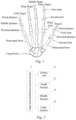
- Fig. 1 is the skeletal structure of a right hand viewed from a palm side.
- the skeletal structure of a right hand is shown in Fig. 1 , in which metacarpal bones of a thumb, an index finger, a middle finger, a ring finger and a little finger are connected to a carpal bone.
- the metacarpal bone of the thumb is connected to phalanges composed of a "proximal phalanx" and a "distal phalanx".
- the distal phalanx of a fingertip is connected to the proximal phalanx through a "first joint”
- the proximal phalanx is connected to the metacarpal bone of the thumb through a "second joint".
- metacarpal bones of the index finger, middle finger, ring finger and little finger are respectively connected to phalanges composed of a "proximal phalanx", a “middle phalanx” and a "distal phalanx".
- the distal phalanx of the fingertip is connected to the middle phalanx through a "first joint”
- the middle phalanx is connected to the proximal phalanx through a "second joint”.
- the proximal phalanx is connected to the metacarpal bone through a "third joint".
- the part of a finger where a distal phalanx is used as a bone is referred to as a "distal part”
- the part of a finger where a middle phalanx is used as a bone is referred to as a "middle part”.
- the part of a finger where a proximal phalanx is used as a bone is referred to as a "proximal part”.
- the part where a "metacarpal bone” is used as a bone is referred to as a "metacarpal part”.
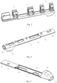
- Fig. 2 is a frame diagram of a finger joint rehabilitation exercise aid part, which comprises a rubber part 11, a small bracket 12, a middle bracket 13 and a large bracket 14.
- the small bracket 12, the middle bracket 13 and the large bracket 14 are all fixed on the rubber part 11, and a power source corrugated tube 3 is fixed by means of a small bracket 12, the middle bracket 13 and the large bracket 14.
- the finger joint rehabilitation exercise aid part can be worn on each finger, but the fingers are different in length and bone structure such that the rubber part structure and the number of small brackets to be worn on each finger will be different. Since the distal phalanx of each finger is short, the power source, such as a corrugated tube, is fixed with a small bracket 12, the distal phalanx of the finger is forced to exercise under the action of the power source, and the fixed position of the small bracket 12 on the rubber part corresponds to the distal phalanx of the finger.
- the power source such as a corrugated tube
- the index finger, the middle finger, the ring finger and the little finger all have a middle phalanx, and since the middle phalanx is slightly shorter than the proximal phalanx, the power source is also fixed with a small bracket 12 to prevent the power source from being detached from the rubber part and thus not being able to drive the finger by means of the rubber part, and at this moment the fixed position of the small bracket 12 on the rubber part is in the middle of the middle phalanx of the finger.
- a middle bracket 13 is provided on the rubber part to be worn on the thumb at the position of the proximal phalanx close to first joint so as to fix the power source, and in addition, middle brackets 13 are provided on the rubber parts to be worn on the index finger, the middle finger, the ring finger and the little finger at the position of the corresponding middle phalanx close to the second joint so as to fix the power source.
- the large brackets 14 are provided on the rubber part to be worn on the five fingers at positions respectively corresponding to the end of the proximal phalanx and the metacarpal bone so as to fix the power source.
- one small bracket 12, one middle bracket 13 and one large bracket 14 are provided on the rubber part to be worn on the thumb, and two small brackets 12, one middle bracket 13 and one large bracket 14 are provided on the other four fingers, such that the rubber part to be worn on the thumb is different in structure from the rubber parts to be worn on the other four fingers.
- Fig.3 is a structural diagram of a finger joint rehabilitation exercise aid part, which can be worn on the index finger, the middle finger, the ring finger and the little finger, which comprises a rubber part 11, a small bracket 12, a middle bracket 13 and a large bracket 14.
- the small bracket 12, the middle bracket 13 and the large bracket 14 are all fixed on the rubber part 11.
- the rubber part 11 can be sheathed on a patient's finger, and the material thereof is rubber, especially medical silicone, and has strong flexibility to adapt to different deformation of the patient's finger.
- Figs. 4 and 5 are respectively the front side and the reverse side of the rubber part 11.
- the front side of the rubber part 11 is provided with multiple raised cylinders 111 for fixing the small bracket 12, the middle bracket 13 and the large bracket 14 to the rubber part 11, with the number of the raised cylinders 111 being the same as the total number of the small bracket 12, the middle bracket 13 and the large bracket 14.
- a front end of the rubber part 11 has a finger sheath 112, which is open at a front end thereof, that is, the rubber part 11 has an open end 113, and the patient's finger reaches into the finger sheath 12 and out from the open end 113, so that the patient's finger is exposed, which can improve the patient's finger touch and is advantageous for the rehabilitation of the patient's fingers.
- the finger sheath 112 is provided, at a position where it is in contact with the finger pulp, with a flat face segment 1121 for supporting the finger, and the finger is kept straight when it is forced to straighten under the drive of the power source.
- a ring opening 114 is provided between the small bracket 12 and the middle bracket 13 and/or between the middle bracket 13 and the large bracket 14 on the rubber part 11, which improves the flexibility of the rubber part at the periphery of the ring opening 114, and when the patient's finger bends and spreads, the rubber part 11 with the ring opening 114 tightly fits with the patient's finger, which is more helpful for the patient to perform follow action with the aid of the finger joint rehabilitation exercise aid part, facilitating rehabilitation of the patient.
- the rubber part 11 is further provided with a hole 115 for fixing the rubber part 11 to other aid structures through the hole 115.
- the curvature of a curved surface 116 of the back side of the rubber part 11 cooperating with the finger is greater than that of a curved surface 117, which facilitates closely fitting to the patient's finger, such that when the rubber part 11 is driven by the power source to bend and stretch, the patient's finger can accurately and synchronously move therewith without lag, and the curvature of the curved surface 117 is smaller for fixedly connection with other aid parts.
- Figs. 6, 7 and 8 are respectively structural diagrams of the small bracket 12, the middle bracket 13 and the large bracket 14.
- the small bracket 12 has a fixing hole 121 such that a power source, such as a corrugated tube, that forces the rubber part 11 to bend and straighten is placed into the fixing hole 121 and is fixed, and a fixing hole 122 that cooperates with the cylinder 111 such that when the cylinder 111 extends into the hole 122, the small bracket is fixed onto the rubber part 11.
- a power source such as a corrugated tube
- the structure of the middle bracket 13 is the same as that of the small bracket 12, except that when the middle bracket 13 and the small bracket 12 are fixed on the rubber part 11, the length of the middle bracket 13 in the lengthwise direction of the finger is greater than the length of the small bracket 12, the middle bracket 13 is further provided with a fixing hole 131 such that a power source, such as a corrugated tube, that forces the rubber part 11 to bend and straighten, is placed into the large hole 131 and is fixed, and a fixing hole 132 that cooperates with the cylinder 111 such that the middle bracket is fixed on the rubber part 11.
- a power source such as a corrugated tube
- the large bracket 14 is different in structure from the small bracket 12 and the middle bracket 13, the large bracket 14 has a greater length and is provided with two holes 141 that cooperate with the cylinder 111 to facilitate fixing the large bracket 14 onto the rubber part 11.
- the large bracket is further provided with a fixing hole 142 such that a power source, such as a corrugated tube, that forces the rubber part 11 to bend and straighten is placed into the large hole 142 and is fixed, and a hole 143 through which the large bracket 14, the rubber part 11 and other aid parts are fixed together.
- the materials thereof are all lightweight materials, such as plastic.
- the finger joint rehabilitation exercise aid parts on the index finger, the middle finger, the ring finger and the little finger have the same structure, but the four fingers are different in length, so that the length of the rubber parts will be different, and the distance between the corresponding cylinders 111 will be adjusted.
- the finger joint rehabilitation exercise aid part is driven by the power source to bend and stretch and at the same time drives the patient's fingers to perform bending and stretching exercise, thereby helping the patient perform rehabilitation training.
- the difference between the finger joint rehabilitation exercise aid part to be worn on the thumb and the finger joint rehabilitation exercise aid parts to be worn on other fingers lies in that one small bracket is fixed on the rubber part to be worn on the thumb, and two small brackets are fixed on the rubber part to be worn on other fingers, so the rubber parts to be worn on the thumb have different technical features from the rubber parts to be worn on other fingers.
- Fig. 9 is a finger joint rehabilitation exercise aid part to be worn on the thumb, which comprises a rubber part 21, a small bracket 22, a middle bracket 23 and a large bracket 24, wherein the small bracket 22, the middle bracket 23 and the large bracket 24 are fixed on the rubber part 21, and the power source corrugated tube 3 is fixed with the small bracket 22, the middle bracket 23 and the large bracket 24.
- Fig. 10 is a rubber part 21 to be worn on the thumb.
- the thumb has only three joints, including the distal phalanx, the proximal phalanx and the metacarpal bone. Since the distal phalanx is relatively short, a small bracket 22 is provided on the rubber part 21 to fix the power source (corrugated tube); since the proximal phalanx and the metacarpal bone are relatively long, the middle bracket 23 is provided on the rubber part at a position corresponding to the proximal phalanx close to the first joint of the thumb so as to fix the power source (corrugated tube), and the large bracket 24 is provided on the rubber part 21 at a position corresponding to the end of the proximal phalanx and the metacarpal bone so as to fix the power source (corrugated tube); and the rubber part 21 to be worn on the thumb is provided with four raised cylinders 211 (the same as the cylinder 111) respectively used for fixing the small bracket 22, the middle bracket 23 and the large bracket 24.
- the small bracket with a smaller length is provided on the rubber part at the position corresponding to the shorter distal phalanx
- the middle bracket 23 and the large bracket 24 are respectively provided on the rubber part at the position corresponding to the longer proximal phalanx and the metacarpal bone, so that the rubber part fit more closely to the power source, which is more advantageous for controlling the deformation of the rubber part to allow the rubber part to fit on the finger, so that the power source (corrugated tube) controls the bending and stretching of the finger.
- the rubber part 21 is provided with a ring hole 214 (the same as the ring hole 114) is provided between the small bracket 22 and the middle bracket 23 and/or between the middle bracket 23 and the large bracket 24, the rubber part 11 to be worn on other fingers is provided with three ring holes, and providing the ring holes is advantageous for improving the fitting of the rubber part to the patient's finger.
- the rubber part 21 is also provided with a finger sheath 212, with a front end thereof having an opening 213, so that the patient's finger reaches into the finger sheath 212, and the fingertip is exposed out of the opening 213, the finger being exposed to the outside improving the patient's finger touch, which is advantageous for the rehabilitation of the patient.
- the rubber part 21 is provided with a hole 215, such that the rubber part 21 is fixed, through the hole 215, together with other aid parts.
- the small bracket, the middle bracket and the large bracket to be worn on the thumb have the same structure and size as those to be worn on other fingers.
- the finger joint rehabilitation exercise aid part to be worn on the thumb is driven by the power source to bend and stretch and at the same time, drives the patient's fingers to perform bending and stretching exercise, thereby helping the patient perform rehabilitation training.
- the apparatus that controls the air pressure in the corrugated tube is any apparatus that can perform suction, compression and exhaust, such as an electric air pump, a manual air pump, a foot-operated air pump, etc.
Landscapes
- Health & Medical Sciences (AREA)
- Epidemiology (AREA)
- Pain & Pain Management (AREA)
- Physical Education & Sports Medicine (AREA)
- Rehabilitation Therapy (AREA)
- Life Sciences & Earth Sciences (AREA)
- Animal Behavior & Ethology (AREA)
- General Health & Medical Sciences (AREA)
- Public Health (AREA)
- Veterinary Medicine (AREA)
- Rehabilitation Tools (AREA)
Description
- The present invention relates to the technical field of joint exercise aid, and in particular to a part for a finger joint rehabilitation exercise aid.
- It has been clinically confirmed that during early rehabilitation and spontaneous recovery after surgery on a patient's limb or for a patient suffering from injury of cranial nerves, implementation of continuous passive exercise can compensate for patient's lack of active exercise, increase the mobility of the limb, and reduce corresponding complications at the same time. In addition, at present, patients suffer from contracture of fingers due to finger paralysis caused by central nervous injury such as cerebral infarction, in which case, if the patient's fingers can be assisted in exercise, the recovery speed of patient's fingers can be increased.
CN 205 698 416 U discloses a finger joint rehabilitation device comprising a rubber part, a finger sheath, brackets and multiple corrugated tubes for each finger precisely positioned with reference to the joints of the fingers on a wearing member.EP 2 332 508 A1 andWO 2016/056058 A1 disclose finger joint rehabilitation devices with multiple corrugated tubes for each finger.WO 2016/140115 A1 discloses a finger joint rehabilitation device with one corrugated tube for each finger wherein each corrugated tube is fixed on the corresponding finger with two holding portions and a lid portion for inserting the fingertip. The corrugated tube is directly fixed on each finger.US 2013/338556 A1 relates to orthoses used to and not to devices that use power sources to bend and straighten and drive the patient's fingers to perform exercise.WO 2015/191585 A1 discloses actuators which can be used as power sources for a device according toclaim 1 but it does not disclose a finger joint rehabilitation device.WO 2015/102723 A2 discloses a mechanically programmed actuator which is provided inside a sleeve with multiple apertures. - In view of the above teachings, the inventor of the present invention finally obtained the present invention after a long period of research and practice.
- The present invention provides a part for a finger joint rehabilitation exercise aid according to
claim 1. - Preferably, a front end of the finger sheath has an opening from which the patient's finger can reach out, improving the patient's finger touch.
- Preferably, when the small bracket, the middle bracket and the large bracket are fixed on the rubber part, a ring hole is provided in the rubber part between the small bracket and the middle bracket and/or between the middle bracket and the large bracket for improving the flexibility of the rubber part.
- Preferably, a curved surface (116) on the reverse side of the rubber part has a greater curvature than a curved surface (117), facilitating fitting to the patient's finger.
- Preferably, the finger sheath is provided with a flat face segment for supporting the finger.
- Preferably, the small bracket, the middle bracket and the large bracket are all made of a lightweight material.
- Preferably, the material of the rubber part is rubber.
- Compared with the prior art, the beneficial effect of the present invention is as follows: According to the finger joint rehabilitation exercise aid part, the rubber part is sheathed on the patient's finger, the power source is fixed by means of the small bracket, the middle bracket and the large bracket fixed on the rubber part, and the rubber part is forced by the power source to bend and straighten and drives the patient's fingers to perform exercise at the same time, thus helping patients perform rehabilitation training.
- To illustrate the technical solutions in various embodiments of the present invention more clearly, the accompanying drawings to be used in the description of the embodiments will be briefly introduced below.
-
Fig. 1 is a diagram for illustrating the skeletal structure of a human hand; -
Fig. 2 is a frame diagram of a finger joint rehabilitation exercise aid part; -
Fig. 3 is a structural diagram of a finger joint rehabilitation exercise aid part to be worn on an index finger, a middle finger, a ring finger and a little finger; -
Fig. 4 is a front view of a rubber part to be worn on an index finger, a middle finger, a ring finger and a little finger; -
Fig. 5 is a reverse view of a rubber part to be worn on an index finger, a middle finger, a ring finger and a little finger; -
Fig. 6 is a structural diagram of a small bracket; -
Fig. 7 is a structural diagram of a middle bracket; -
Fig. 8 is a structural diagram of a large bracket; -
Fig. 9 is a structural diagram of a finger joint rehabilitation exercise aid part to be worn on a thumb; and -
Fig. 10 is a structural diagram of a rubber part to be worn on a thumb. - The above and other technical features and advantages of the present invention will be illustrated in more detail below with reference to the drawings.
- Before illustration for a joint exercise aid device involved in this embodiment, the skeletal structure of a human hand will be illustrated.
-
Fig. 1 is the skeletal structure of a right hand viewed from a palm side. The skeletal structure of a right hand is shown inFig. 1 , in which metacarpal bones of a thumb, an index finger, a middle finger, a ring finger and a little finger are connected to a carpal bone. The metacarpal bone of the thumb is connected to phalanges composed of a "proximal phalanx" and a "distal phalanx". Regarding the thumb, the distal phalanx of a fingertip is connected to the proximal phalanx through a "first joint", and the proximal phalanx is connected to the metacarpal bone of the thumb through a "second joint". - In addition, metacarpal bones of the index finger, middle finger, ring finger and little finger are respectively connected to phalanges composed of a "proximal phalanx", a "middle phalanx" and a "distal phalanx". Regarding the index finger, the middle finger, the ring finger and the little finger, the distal phalanx of the fingertip is connected to the middle phalanx through a "first joint", and the middle phalanx is connected to the proximal phalanx through a "second joint". Moreover, the proximal phalanx is connected to the metacarpal bone through a "third joint". Furthermore, in the following illustration, the part of a finger where a distal phalanx is used as a bone is referred to as a "distal part", and the part of a finger where a middle phalanx is used as a bone is referred to as a "middle part". In addition, the part of a finger where a proximal phalanx is used as a bone is referred to as a "proximal part". Also, the part where a "metacarpal bone" is used as a bone is referred to as a "metacarpal part".
-
Fig. 2 is a frame diagram of a finger joint rehabilitation exercise aid part, which comprises arubber part 11, asmall bracket 12, amiddle bracket 13 and alarge bracket 14. Thesmall bracket 12, themiddle bracket 13 and thelarge bracket 14 are all fixed on therubber part 11, and a power source corrugated tube 3 is fixed by means of asmall bracket 12, themiddle bracket 13 and thelarge bracket 14. - The finger joint rehabilitation exercise aid part can be worn on each finger, but the fingers are different in length and bone structure such that the rubber part structure and the number of small brackets to be worn on each finger will be different. Since the distal phalanx of each finger is short, the power source, such as a corrugated tube, is fixed with a
small bracket 12, the distal phalanx of the finger is forced to exercise under the action of the power source, and the fixed position of thesmall bracket 12 on the rubber part corresponds to the distal phalanx of the finger. The index finger, the middle finger, the ring finger and the little finger all have a middle phalanx, and since the middle phalanx is slightly shorter than the proximal phalanx, the power source is also fixed with asmall bracket 12 to prevent the power source from being detached from the rubber part and thus not being able to drive the finger by means of the rubber part, and at this moment the fixed position of thesmall bracket 12 on the rubber part is in the middle of the middle phalanx of the finger. The five fingers of one hand all have a proximal phalanx, since the proximal phalanx is longer than the middle phalanx, in order to bring the power source more fit to the finger, amiddle bracket 13 is provided on the rubber part to be worn on the thumb at the position of the proximal phalanx close to first joint so as to fix the power source, and in addition,middle brackets 13 are provided on the rubber parts to be worn on the index finger, the middle finger, the ring finger and the little finger at the position of the corresponding middle phalanx close to the second joint so as to fix the power source. Thelarge brackets 14 are provided on the rubber part to be worn on the five fingers at positions respectively corresponding to the end of the proximal phalanx and the metacarpal bone so as to fix the power source. As such, onesmall bracket 12, onemiddle bracket 13 and onelarge bracket 14 are provided on the rubber part to be worn on the thumb, and twosmall brackets 12, onemiddle bracket 13 and onelarge bracket 14 are provided on the other four fingers, such that the rubber part to be worn on the thumb is different in structure from the rubber parts to be worn on the other four fingers. -
Fig.3 is a structural diagram of a finger joint rehabilitation exercise aid part, which can be worn on the index finger, the middle finger, the ring finger and the little finger, which comprises arubber part 11, asmall bracket 12, amiddle bracket 13 and alarge bracket 14. Thesmall bracket 12, themiddle bracket 13 and thelarge bracket 14 are all fixed on therubber part 11. - The
rubber part 11 can be sheathed on a patient's finger, and the material thereof is rubber, especially medical silicone, and has strong flexibility to adapt to different deformation of the patient's finger.Figs. 4 and 5 are respectively the front side and the reverse side of therubber part 11. The front side of therubber part 11 is provided with multiple raisedcylinders 111 for fixing thesmall bracket 12, themiddle bracket 13 and thelarge bracket 14 to therubber part 11, with the number of the raisedcylinders 111 being the same as the total number of thesmall bracket 12, themiddle bracket 13 and thelarge bracket 14. A front end of therubber part 11 has afinger sheath 112, which is open at a front end thereof, that is, therubber part 11 has anopen end 113, and the patient's finger reaches into thefinger sheath 12 and out from theopen end 113, so that the patient's finger is exposed, which can improve the patient's finger touch and is advantageous for the rehabilitation of the patient's fingers. Thefinger sheath 112 is provided, at a position where it is in contact with the finger pulp, with aflat face segment 1121 for supporting the finger, and the finger is kept straight when it is forced to straighten under the drive of the power source. Aring opening 114 is provided between thesmall bracket 12 and themiddle bracket 13 and/or between themiddle bracket 13 and thelarge bracket 14 on therubber part 11, which improves the flexibility of the rubber part at the periphery of thering opening 114, and when the patient's finger bends and spreads, therubber part 11 with thering opening 114 tightly fits with the patient's finger, which is more helpful for the patient to perform follow action with the aid of the finger joint rehabilitation exercise aid part, facilitating rehabilitation of the patient. Therubber part 11 is further provided with ahole 115 for fixing therubber part 11 to other aid structures through thehole 115. The curvature of acurved surface 116 of the back side of therubber part 11 cooperating with the finger is greater than that of acurved surface 117, which facilitates closely fitting to the patient's finger, such that when therubber part 11 is driven by the power source to bend and stretch, the patient's finger can accurately and synchronously move therewith without lag, and the curvature of thecurved surface 117 is smaller for fixedly connection with other aid parts. -
Figs. 6, 7 and8 are respectively structural diagrams of thesmall bracket 12, themiddle bracket 13 and thelarge bracket 14. InFig. 6 , thesmall bracket 12 has a fixinghole 121 such that a power source, such as a corrugated tube, that forces therubber part 11 to bend and straighten is placed into the fixinghole 121 and is fixed, and a fixinghole 122 that cooperates with thecylinder 111 such that when thecylinder 111 extends into thehole 122, the small bracket is fixed onto therubber part 11. - The structure of the
middle bracket 13 is the same as that of thesmall bracket 12, except that when themiddle bracket 13 and thesmall bracket 12 are fixed on therubber part 11, the length of themiddle bracket 13 in the lengthwise direction of the finger is greater than the length of thesmall bracket 12, themiddle bracket 13 is further provided with a fixinghole 131 such that a power source, such as a corrugated tube, that forces therubber part 11 to bend and straighten, is placed into thelarge hole 131 and is fixed, and a fixinghole 132 that cooperates with thecylinder 111 such that the middle bracket is fixed on therubber part 11. - The
large bracket 14 is different in structure from thesmall bracket 12 and themiddle bracket 13, thelarge bracket 14 has a greater length and is provided with twoholes 141 that cooperate with thecylinder 111 to facilitate fixing thelarge bracket 14 onto therubber part 11. The large bracket is further provided with a fixinghole 142 such that a power source, such as a corrugated tube, that forces therubber part 11 to bend and straighten is placed into thelarge hole 142 and is fixed, and ahole 143 through which thelarge bracket 14, therubber part 11 and other aid parts are fixed together. - Since the
small bracket 12, themiddle bracket 13 and thelarge bracket 14 need to be worn for a long time, the materials thereof are all lightweight materials, such as plastic. - The finger joint rehabilitation exercise aid parts on the index finger, the middle finger, the ring finger and the little finger have the same structure, but the four fingers are different in length, so that the length of the rubber parts will be different, and the distance between the corresponding
cylinders 111 will be adjusted. - The finger joint rehabilitation exercise aid part is driven by the power source to bend and stretch and at the same time drives the patient's fingers to perform bending and stretching exercise, thereby helping the patient perform rehabilitation training.
- The difference between the finger joint rehabilitation exercise aid part to be worn on the thumb and the finger joint rehabilitation exercise aid parts to be worn on other fingers lies in that one small bracket is fixed on the rubber part to be worn on the thumb, and two small brackets are fixed on the rubber part to be worn on other fingers, so the rubber parts to be worn on the thumb have different technical features from the rubber parts to be worn on other fingers.
-
Fig. 9 is a finger joint rehabilitation exercise aid part to be worn on the thumb, which comprises arubber part 21, asmall bracket 22, a middle bracket 23 and alarge bracket 24, wherein thesmall bracket 22, the middle bracket 23 and thelarge bracket 24 are fixed on therubber part 21, and the power source corrugated tube 3 is fixed with thesmall bracket 22, the middle bracket 23 and thelarge bracket 24. -
Fig. 10 is arubber part 21 to be worn on the thumb. The thumb has only three joints, including the distal phalanx, the proximal phalanx and the metacarpal bone. Since the distal phalanx is relatively short, asmall bracket 22 is provided on therubber part 21 to fix the power source (corrugated tube); since the proximal phalanx and the metacarpal bone are relatively long, the middle bracket 23 is provided on the rubber part at a position corresponding to the proximal phalanx close to the first joint of the thumb so as to fix the power source (corrugated tube), and thelarge bracket 24 is provided on therubber part 21 at a position corresponding to the end of the proximal phalanx and the metacarpal bone so as to fix the power source (corrugated tube); and therubber part 21 to be worn on the thumb is provided with four raised cylinders 211 (the same as the cylinder 111) respectively used for fixing thesmall bracket 22, the middle bracket 23 and thelarge bracket 24. As such, the small bracket with a smaller length is provided on the rubber part at the position corresponding to the shorter distal phalanx, and the middle bracket 23 and thelarge bracket 24 are respectively provided on the rubber part at the position corresponding to the longer proximal phalanx and the metacarpal bone, so that the rubber part fit more closely to the power source, which is more advantageous for controlling the deformation of the rubber part to allow the rubber part to fit on the finger, so that the power source (corrugated tube) controls the bending and stretching of the finger. Therubber part 21 is provided with a ring hole 214 (the same as the ring hole 114) is provided between thesmall bracket 22 and the middle bracket 23 and/or between the middle bracket 23 and thelarge bracket 24, therubber part 11 to be worn on other fingers is provided with three ring holes, and providing the ring holes is advantageous for improving the fitting of the rubber part to the patient's finger. Therubber part 21 is also provided with afinger sheath 212, with a front end thereof having anopening 213, so that the patient's finger reaches into thefinger sheath 212, and the fingertip is exposed out of theopening 213, the finger being exposed to the outside improving the patient's finger touch, which is advantageous for the rehabilitation of the patient. Also, therubber part 21 is provided with ahole 215, such that therubber part 21 is fixed, through thehole 215, together with other aid parts. The small bracket, the middle bracket and the large bracket to be worn on the thumb have the same structure and size as those to be worn on other fingers. - As such, the finger joint rehabilitation exercise aid part to be worn on the thumb is driven by the power source to bend and stretch and at the same time, drives the patient's fingers to perform bending and stretching exercise, thereby helping the patient perform rehabilitation training.
- The apparatus that controls the air pressure in the corrugated tube is any apparatus that can perform suction, compression and exhaust, such as an electric air pump, a manual air pump, a foot-operated air pump, etc.
- The above are only the preferred embodiments of the present invention, and are merely illustrative but not restrictive for the present invention. It will be understood by those skilled in the art that many changes, modifications and equivalents can be made within the scope of the claims.
Claims (5)
- A part for a finger joint rehabilitation exercise aid, wherein the rehabilitation exercise aid comprises a single power source corrugated tube for each finger, and wherein the part comprises a rubber part (11) which is configured to be worn by the patient such that, is use, the power source corrugated tube forces the rubber part to bend and straighten and drives the patient's finger to perform exercise, the part further comprises:at least one small bracket (12), one middle bracket (13) and one large bracket (14), wherein the small bracket (12), the middle bracket (13) and the large bracket (14) are fixed on the rubber part (11), with the positions of the small bracket (12), the middle bracket (13) and the large bracket (14) fixed on the rubber part (11) respectively corresponding to a distal phalanx/middle phalanx, a proximal phalanx and a metacarpal bone;the small bracket (12), the middle bracket (13) and the large bracket (14) are each provided with a fixing hole (121,131,142) for fixing the power source corrugated tube;the rubber part (11) is further provided with a hole (115) for fixing the rubber part (11) to another aid structure through the hole (115);a front end of the rubber part (11) is provided with a finger sheath (212) into which a patient's finger can reach;the reverse side of the rubber part (11) is provided with a curved surface (116), so as to facilitate fitting to the patient's finger;the rubber part (11) is provided with at least four raised cylinders (111), and the small bracket (12), the middle bracket (13) and the large bracket (14) are all provided with holes that cooperate with the cylinders.
- The finger joint rehabilitation exercise aid part according to claim 1, characterized in that a front end of the finger sheath has an opening (213) from which the patient's finger can reach out, improving the patient's finger touch.
- The finger joint rehabilitation exercise aid part according to claim 2, characterized in that when the small bracket (12), the middle bracket (13) and the large bracket (14) are fixed on the rubber part (11), a ring hole (114) is provided in the rubber part (11) between the small bracket (12) and the middle bracket (13) and/or between the middle bracket (13) and the large bracket (14) for improving the flexibility of the rubber part (11).
- The finger joint rehabilitation exercise aid part according to claim 3, characterized in that the finger sheath is provided with a flat face segment (1121) for supporting the finger.
- The finger joint rehabilitation exercise aid part according to any one of claims 1-4, characterized in that the small bracket (12), the middle bracket (13) and the large bracket (14) are all made of a lightweight material.
Applications Claiming Priority (2)
| Application Number | Priority Date | Filing Date | Title |
|---|---|---|---|
| CN201710552259.0A CN107184365B (en) | 2017-07-07 | 2017-07-07 | A kind of finger joint recovery movement auxiliary member |
| PCT/CN2018/094199 WO2019007314A1 (en) | 2017-07-07 | 2018-07-03 | Knuckle rehabilitation exercise aid |
Publications (3)
| Publication Number | Publication Date |
|---|---|
| EP3632394A1 EP3632394A1 (en) | 2020-04-08 |
| EP3632394A4 EP3632394A4 (en) | 2020-06-17 |
| EP3632394B1 true EP3632394B1 (en) | 2023-08-23 |
Family
ID=59883564
Family Applications (1)
| Application Number | Title | Priority Date | Filing Date |
|---|---|---|---|
| EP18827647.1A Active EP3632394B1 (en) | 2017-07-07 | 2018-07-03 | Knuckle rehabilitation exercise aid |
Country Status (6)
| Country | Link |
|---|---|
| US (1) | US10780011B2 (en) |
| EP (1) | EP3632394B1 (en) |
| JP (1) | JP6779395B2 (en) |
| CN (1) | CN107184365B (en) |
| ES (1) | ES2959868T3 (en) |
| WO (1) | WO2019007314A1 (en) |
Families Citing this family (17)
| Publication number | Priority date | Publication date | Assignee | Title |
|---|---|---|---|---|
| US10611020B2 (en) | 2013-12-19 | 2020-04-07 | Roam Robotics Inc. | Pneumatic exomuscle system and method |
| JP7541825B2 (en) | 2017-02-03 | 2024-08-29 | ローム ロボティクス インコーポレイテッド | System and method for user intent recognition |
| CN107184365B (en) | 2017-07-07 | 2019-04-05 | 北京恒通信佳科技发展有限公司 | A kind of finger joint recovery movement auxiliary member |
| CN108371610B (en) * | 2018-03-27 | 2019-11-12 | 华中科技大学 | Modular soft rehabilitation glove and system for assisting finger extension |
| CN108354779B (en) * | 2018-03-27 | 2019-11-12 | 华中科技大学 | A software driver for assisting human hand's four-finger stretching |
| CN108371609B (en) * | 2018-03-27 | 2020-02-14 | 华中科技大学 | Soft driver for assisting extension and abduction of thumb of human hand |
| CA3161113A1 (en) * | 2019-12-13 | 2021-06-17 | Kyle Allen LAMSON | Powered device to benefit a wearer during skiing |
| CN111317975B (en) * | 2020-02-28 | 2021-05-07 | 南开大学 | a finger rehabilitation facility |
| WO2021242974A1 (en) | 2020-05-27 | 2021-12-02 | Roam Robotics Inc. | Fit and suspension systems and methods for a mobile robot |
| CN115720514A (en) | 2020-05-27 | 2023-02-28 | 漫游机械人技术公司 | User interface and feedback system and method for mobile robot |
| US12115663B2 (en) | 2021-08-17 | 2024-10-15 | Roam Robotics Inc. | Maritime applications for a mobile robot |
| EP4387815A4 (en) | 2021-08-17 | 2025-05-07 | Roam Robotics Inc. | ACTUATOR FEATURES TO IMPROVE THE FUNCTION OF A MOBILE ROBOT |
| US12466060B2 (en) | 2021-08-17 | 2025-11-11 | Roam Robotics Inc. | Mobile power source for a mobile robot |
| WO2023023563A1 (en) | 2021-08-17 | 2023-02-23 | Roam Robotics Inc. | Cable management systems and methods for a wearable mobile robot |
| CN114869691B (en) * | 2022-05-16 | 2025-12-12 | 江苏益通生物科技有限公司 | A rehabilitation aid for finger nerve injury with safety protection features |
| KR102633393B1 (en) * | 2023-01-25 | 2024-02-05 | 박효준 | Assist device for active finger movement |
| CN117205039A (en) * | 2023-03-10 | 2023-12-12 | 广东今甲机器人有限公司 | Structure to prevent recovery gloves from deflecting |
Family Cites Families (25)
| Publication number | Priority date | Publication date | Assignee | Title |
|---|---|---|---|---|
| US4274399A (en) * | 1980-01-29 | 1981-06-23 | Jobst Institute, Inc. | Therapeutic appliance for flexing joints |
| US4671258A (en) * | 1984-01-12 | 1987-06-09 | Barthlome Donald E | Therapeutic multiple joint exerciser |
| US6565563B1 (en) * | 1996-09-23 | 2003-05-20 | John M. Agee | Method and apparatus for increasing the range of motion of one or more contracted joints through external forces independently transmitted to the skeleton |
| US20100280424A1 (en) * | 2008-03-27 | 2010-11-04 | Panasonic Corporation | Muscle force assisting device |
| JP5472680B2 (en) * | 2009-04-09 | 2014-04-16 | 国立大学法人 筑波大学 | Wearable motion assist device |
| JP4716456B2 (en) * | 2009-10-05 | 2011-07-06 | 圭治郎 山本 | Joint motion support device |
| US9120220B2 (en) * | 2012-02-29 | 2015-09-01 | GM Global Technology Operations LLC | Control of a glove-based grasp assist device |
| US9764190B2 (en) * | 2012-06-13 | 2017-09-19 | Saebo, Inc. | Dynamic hand splints |
| US9492930B2 (en) * | 2013-10-18 | 2016-11-15 | President And Fellows Of Harvard College | Mechanically programmed soft actuators with conforming sleeves |
| US10184500B2 (en) * | 2013-10-29 | 2019-01-22 | President And Fellows Of Harvard College | Multi-segment reinforced actuators and applications |
| US10012229B2 (en) * | 2013-12-19 | 2018-07-03 | Other Lab Llc | Diaphragm compressor system and method |
| US10611020B2 (en) * | 2013-12-19 | 2020-04-07 | Roam Robotics Inc. | Pneumatic exomuscle system and method |
| CN107002721A (en) * | 2014-06-09 | 2017-08-01 | 软机器人公司 | Soft robotic actuators using asymmetric surfaces |
| GB2541623A (en) * | 2014-06-12 | 2017-02-22 | Nat Univ Singapore | Actuator device, method and system for limb rehabilitation |
| CN204121369U (en) * | 2014-08-06 | 2015-01-28 | 张晓雲 | Maintenance and rehabilitation device for the function of the metacarpophalangeal joints of the hand |
| WO2016056058A1 (en) * | 2014-10-07 | 2016-04-14 | 圭治郎 山本 | Joint movement assist device |
| JP2016159049A (en) * | 2015-03-04 | 2016-09-05 | 学校法人幾徳学園 | Finger joint rehabilitation device |
| US9968506B2 (en) * | 2015-07-25 | 2018-05-15 | Luis Cruz | Therapeutic system and method for flexing and extending metacarpal and phalangeal joints |
| US20190015233A1 (en) * | 2016-01-05 | 2019-01-17 | President And Fellows Of Harvard College | Fabric-Based Soft Actuators |
| CA3015906A1 (en) * | 2016-02-25 | 2017-08-31 | Cornell University | Waveguides for use in sensors or displays |
| CN205698416U (en) * | 2016-04-01 | 2016-11-23 | 北京所乐思国际商务有限公司 | A kind of joint motions auxiliary device of independent subjoint |
| CN109152691B (en) * | 2016-05-19 | 2021-03-05 | 山本圭治郎 | Joint movement assistance system |
| CN106880470B (en) * | 2017-03-07 | 2023-05-09 | 浙江大学 | Multi-degree-of-freedom deformation structure and wearing type action auxiliary device comprising same |
| US11129766B2 (en) * | 2017-04-14 | 2021-09-28 | The Chinese University Of Hong Kong | Flexibly driven robotic hands |
| CN107184365B (en) * | 2017-07-07 | 2019-04-05 | 北京恒通信佳科技发展有限公司 | A kind of finger joint recovery movement auxiliary member |
-
2017
- 2017-07-07 CN CN201710552259.0A patent/CN107184365B/en active Active
-
2018
- 2018-07-03 JP JP2019568347A patent/JP6779395B2/en active Active
- 2018-07-03 ES ES18827647T patent/ES2959868T3/en active Active
- 2018-07-03 EP EP18827647.1A patent/EP3632394B1/en active Active
- 2018-07-03 US US16/626,579 patent/US10780011B2/en active Active
- 2018-07-03 WO PCT/CN2018/094199 patent/WO2019007314A1/en not_active Ceased
Also Published As
| Publication number | Publication date |
|---|---|
| US10780011B2 (en) | 2020-09-22 |
| WO2019007314A1 (en) | 2019-01-10 |
| ES2959868T3 (en) | 2024-02-28 |
| EP3632394A1 (en) | 2020-04-08 |
| JP2020526246A (en) | 2020-08-31 |
| CN107184365A (en) | 2017-09-22 |
| US20200129364A1 (en) | 2020-04-30 |
| CN107184365B (en) | 2019-04-05 |
| JP6779395B2 (en) | 2020-11-04 |
| EP3632394A4 (en) | 2020-06-17 |
Similar Documents
| Publication | Publication Date | Title |
|---|---|---|
| US10780011B2 (en) | Finger joint rehabilitation exercise aid part | |
| EP3632396B1 (en) | Knuckle rehabilitation device | |
| JP2020526246A5 (en) | ||
| CN108621129B (en) | Flexible driving type mechanical arm | |
| CN110711110B (en) | Push-down under-actuated finger rehabilitation training device | |
| CN102811690B (en) | hand rehabilitation device | |
| CN106983634A (en) | A kind of exoskeleton finger functional rehabilitation device based on multistage continuous structure | |
| US10993869B2 (en) | Finger motion aid and rehabilitation hand having same | |
| CN215021628U (en) | Pneumatic rehabilitation glove | |
| JP6279143B2 (en) | Joint motion assist device and method for mounting the joint motion assist device | |
| CN109893400B (en) | Finger bending and stretching movement mechanism for exoskeleton hand rehabilitation robot | |
| Jiralerspong et al. | A novel soft robotic glove for daily life assistance | |
| CN107693175A (en) | A kind of artificial limb manipulator and its arm | |
| CN106264982A (en) | Instrument is corrected in hand rehabilitation training | |
| CN110393896B (en) | A soft robotic glove for hand function rehabilitation training and control method | |
| CN113576832B (en) | Line drive modularization software rehabilitation gloves | |
| CN203777261U (en) | Hand metacarpal finger rehabilitation exercise device | |
| CN104771288A (en) | Hand metacarpal finger rehabilitation practice method and device thereof | |
| CN209933408U (en) | Finger bending and stretching movement mechanism for exoskeleton hand rehabilitation robot | |
| KR20120130974A (en) | Gripper apparatus for wearable robot | |
| CN215021682U (en) | Recovered gloves based on speech control | |
| CN110665192B (en) | Recovered type ectoskeleton gloves robot | |
| CN221331786U (en) | A detachable pneumatic soft rehabilitation robot | |
| CN115813718B (en) | A soft rehabilitation glove | |
| CN110916978B (en) | Hand fracture rehabilitation robot |
Legal Events
| Date | Code | Title | Description |
|---|---|---|---|
| STAA | Information on the status of an ep patent application or granted ep patent |
Free format text: STATUS: THE INTERNATIONAL PUBLICATION HAS BEEN MADE |
|
| PUAI | Public reference made under article 153(3) epc to a published international application that has entered the european phase |
Free format text: ORIGINAL CODE: 0009012 |
|
| STAA | Information on the status of an ep patent application or granted ep patent |
Free format text: STATUS: REQUEST FOR EXAMINATION WAS MADE |
|
| 17P | Request for examination filed |
Effective date: 20191230 |
|
| AK | Designated contracting states |
Kind code of ref document: A1 Designated state(s): AL AT BE BG CH CY CZ DE DK EE ES FI FR GB GR HR HU IE IS IT LI LT LU LV MC MK MT NL NO PL PT RO RS SE SI SK SM TR |
|
| AX | Request for extension of the european patent |
Extension state: BA ME |
|
| RIN1 | Information on inventor provided before grant (corrected) |
Inventor name: YANG, KEQIANG Inventor name: YAMAMOTO, KEIJIRON Inventor name: MAO, ZHENWEI |
|
| A4 | Supplementary search report drawn up and despatched |
Effective date: 20200514 |
|
| RIC1 | Information provided on ipc code assigned before grant |
Ipc: A61H 1/02 20060101AFI20200508BHEP Ipc: A61H 1/00 20060101ALI20200508BHEP |
|
| RIN1 | Information on inventor provided before grant (corrected) |
Inventor name: MAO, ZHENWEI Inventor name: YAMAMOTO, KEIJIRON Inventor name: YANG, KEQIANG |
|
| DAV | Request for validation of the european patent (deleted) | ||
| DAX | Request for extension of the european patent (deleted) | ||
| STAA | Information on the status of an ep patent application or granted ep patent |
Free format text: STATUS: EXAMINATION IS IN PROGRESS |
|
| 17Q | First examination report despatched |
Effective date: 20201118 |
|
| GRAP | Despatch of communication of intention to grant a patent |
Free format text: ORIGINAL CODE: EPIDOSNIGR1 |
|
| STAA | Information on the status of an ep patent application or granted ep patent |
Free format text: STATUS: GRANT OF PATENT IS INTENDED |
|
| RIC1 | Information provided on ipc code assigned before grant |
Ipc: A61H 1/02 20060101AFI20230213BHEP |
|
| INTG | Intention to grant announced |
Effective date: 20230314 |
|
| GRAS | Grant fee paid |
Free format text: ORIGINAL CODE: EPIDOSNIGR3 |
|
| GRAA | (expected) grant |
Free format text: ORIGINAL CODE: 0009210 |
|
| STAA | Information on the status of an ep patent application or granted ep patent |
Free format text: STATUS: THE PATENT HAS BEEN GRANTED |
|
| AK | Designated contracting states |
Kind code of ref document: B1 Designated state(s): AL AT BE BG CH CY CZ DE DK EE ES FI FR GB GR HR HU IE IS IT LI LT LU LV MC MK MT NL NO PL PT RO RS SE SI SK SM TR |
|
| REG | Reference to a national code |
Ref country code: GB Ref legal event code: FG4D |
|
| REG | Reference to a national code |
Ref country code: CH Ref legal event code: EP |
|
| REG | Reference to a national code |
Ref country code: IE Ref legal event code: FG4D |
|
| REG | Reference to a national code |
Ref country code: DE Ref legal event code: R096 Ref document number: 602018056072 Country of ref document: DE |
|
| REG | Reference to a national code |
Ref country code: LT Ref legal event code: MG9D |
|
| REG | Reference to a national code |
Ref country code: NL Ref legal event code: MP Effective date: 20230823 |
|
| REG | Reference to a national code |
Ref country code: AT Ref legal event code: MK05 Ref document number: 1601728 Country of ref document: AT Kind code of ref document: T Effective date: 20230823 |
|
| PG25 | Lapsed in a contracting state [announced via postgrant information from national office to epo] |
Ref country code: GR Free format text: LAPSE BECAUSE OF FAILURE TO SUBMIT A TRANSLATION OF THE DESCRIPTION OR TO PAY THE FEE WITHIN THE PRESCRIBED TIME-LIMIT Effective date: 20231124 |
|
| PG25 | Lapsed in a contracting state [announced via postgrant information from national office to epo] |
Ref country code: IS Free format text: LAPSE BECAUSE OF FAILURE TO SUBMIT A TRANSLATION OF THE DESCRIPTION OR TO PAY THE FEE WITHIN THE PRESCRIBED TIME-LIMIT Effective date: 20231223 |
|
| PG25 | Lapsed in a contracting state [announced via postgrant information from national office to epo] |
Ref country code: SE Free format text: LAPSE BECAUSE OF FAILURE TO SUBMIT A TRANSLATION OF THE DESCRIPTION OR TO PAY THE FEE WITHIN THE PRESCRIBED TIME-LIMIT Effective date: 20230823 Ref country code: RS Free format text: LAPSE BECAUSE OF FAILURE TO SUBMIT A TRANSLATION OF THE DESCRIPTION OR TO PAY THE FEE WITHIN THE PRESCRIBED TIME-LIMIT Effective date: 20230823 Ref country code: PT Free format text: LAPSE BECAUSE OF FAILURE TO SUBMIT A TRANSLATION OF THE DESCRIPTION OR TO PAY THE FEE WITHIN THE PRESCRIBED TIME-LIMIT Effective date: 20231226 Ref country code: NO Free format text: LAPSE BECAUSE OF FAILURE TO SUBMIT A TRANSLATION OF THE DESCRIPTION OR TO PAY THE FEE WITHIN THE PRESCRIBED TIME-LIMIT Effective date: 20231123 Ref country code: NL Free format text: LAPSE BECAUSE OF FAILURE TO SUBMIT A TRANSLATION OF THE DESCRIPTION OR TO PAY THE FEE WITHIN THE PRESCRIBED TIME-LIMIT Effective date: 20230823 Ref country code: LV Free format text: LAPSE BECAUSE OF FAILURE TO SUBMIT A TRANSLATION OF THE DESCRIPTION OR TO PAY THE FEE WITHIN THE PRESCRIBED TIME-LIMIT Effective date: 20230823 Ref country code: LT Free format text: LAPSE BECAUSE OF FAILURE TO SUBMIT A TRANSLATION OF THE DESCRIPTION OR TO PAY THE FEE WITHIN THE PRESCRIBED TIME-LIMIT Effective date: 20230823 Ref country code: IS Free format text: LAPSE BECAUSE OF FAILURE TO SUBMIT A TRANSLATION OF THE DESCRIPTION OR TO PAY THE FEE WITHIN THE PRESCRIBED TIME-LIMIT Effective date: 20231223 Ref country code: HR Free format text: LAPSE BECAUSE OF FAILURE TO SUBMIT A TRANSLATION OF THE DESCRIPTION OR TO PAY THE FEE WITHIN THE PRESCRIBED TIME-LIMIT Effective date: 20230823 Ref country code: GR Free format text: LAPSE BECAUSE OF FAILURE TO SUBMIT A TRANSLATION OF THE DESCRIPTION OR TO PAY THE FEE WITHIN THE PRESCRIBED TIME-LIMIT Effective date: 20231124 Ref country code: FI Free format text: LAPSE BECAUSE OF FAILURE TO SUBMIT A TRANSLATION OF THE DESCRIPTION OR TO PAY THE FEE WITHIN THE PRESCRIBED TIME-LIMIT Effective date: 20230823 Ref country code: AT Free format text: LAPSE BECAUSE OF FAILURE TO SUBMIT A TRANSLATION OF THE DESCRIPTION OR TO PAY THE FEE WITHIN THE PRESCRIBED TIME-LIMIT Effective date: 20230823 |
|
| REG | Reference to a national code |
Ref country code: ES Ref legal event code: FG2A Ref document number: 2959868 Country of ref document: ES Kind code of ref document: T3 Effective date: 20240228 |
|
| PG25 | Lapsed in a contracting state [announced via postgrant information from national office to epo] |
Ref country code: PL Free format text: LAPSE BECAUSE OF FAILURE TO SUBMIT A TRANSLATION OF THE DESCRIPTION OR TO PAY THE FEE WITHIN THE PRESCRIBED TIME-LIMIT Effective date: 20230823 |
|
| PG25 | Lapsed in a contracting state [announced via postgrant information from national office to epo] |
Ref country code: SM Free format text: LAPSE BECAUSE OF FAILURE TO SUBMIT A TRANSLATION OF THE DESCRIPTION OR TO PAY THE FEE WITHIN THE PRESCRIBED TIME-LIMIT Effective date: 20230823 Ref country code: RO Free format text: LAPSE BECAUSE OF FAILURE TO SUBMIT A TRANSLATION OF THE DESCRIPTION OR TO PAY THE FEE WITHIN THE PRESCRIBED TIME-LIMIT Effective date: 20230823 Ref country code: EE Free format text: LAPSE BECAUSE OF FAILURE TO SUBMIT A TRANSLATION OF THE DESCRIPTION OR TO PAY THE FEE WITHIN THE PRESCRIBED TIME-LIMIT Effective date: 20230823 Ref country code: DK Free format text: LAPSE BECAUSE OF FAILURE TO SUBMIT A TRANSLATION OF THE DESCRIPTION OR TO PAY THE FEE WITHIN THE PRESCRIBED TIME-LIMIT Effective date: 20230823 Ref country code: CZ Free format text: LAPSE BECAUSE OF FAILURE TO SUBMIT A TRANSLATION OF THE DESCRIPTION OR TO PAY THE FEE WITHIN THE PRESCRIBED TIME-LIMIT Effective date: 20230823 Ref country code: SK Free format text: LAPSE BECAUSE OF FAILURE TO SUBMIT A TRANSLATION OF THE DESCRIPTION OR TO PAY THE FEE WITHIN THE PRESCRIBED TIME-LIMIT Effective date: 20230823 |
|
| REG | Reference to a national code |
Ref country code: DE Ref legal event code: R097 Ref document number: 602018056072 Country of ref document: DE |
|
| PLBE | No opposition filed within time limit |
Free format text: ORIGINAL CODE: 0009261 |
|
| STAA | Information on the status of an ep patent application or granted ep patent |
Free format text: STATUS: NO OPPOSITION FILED WITHIN TIME LIMIT |
|
| 26N | No opposition filed |
Effective date: 20240524 |
|
| PG25 | Lapsed in a contracting state [announced via postgrant information from national office to epo] |
Ref country code: SI Free format text: LAPSE BECAUSE OF FAILURE TO SUBMIT A TRANSLATION OF THE DESCRIPTION OR TO PAY THE FEE WITHIN THE PRESCRIBED TIME-LIMIT Effective date: 20230823 |
|
| PG25 | Lapsed in a contracting state [announced via postgrant information from national office to epo] |
Ref country code: BG Free format text: LAPSE BECAUSE OF FAILURE TO SUBMIT A TRANSLATION OF THE DESCRIPTION OR TO PAY THE FEE WITHIN THE PRESCRIBED TIME-LIMIT Effective date: 20230823 |
|
| PG25 | Lapsed in a contracting state [announced via postgrant information from national office to epo] |
Ref country code: BG Free format text: LAPSE BECAUSE OF FAILURE TO SUBMIT A TRANSLATION OF THE DESCRIPTION OR TO PAY THE FEE WITHIN THE PRESCRIBED TIME-LIMIT Effective date: 20230823 |
|
| PG25 | Lapsed in a contracting state [announced via postgrant information from national office to epo] |
Ref country code: MC Free format text: LAPSE BECAUSE OF FAILURE TO SUBMIT A TRANSLATION OF THE DESCRIPTION OR TO PAY THE FEE WITHIN THE PRESCRIBED TIME-LIMIT Effective date: 20230823 |
|
| REG | Reference to a national code |
Ref country code: CH Ref legal event code: PL |
|
| PG25 | Lapsed in a contracting state [announced via postgrant information from national office to epo] |
Ref country code: LU Free format text: LAPSE BECAUSE OF NON-PAYMENT OF DUE FEES Effective date: 20240703 |
|
| PG25 | Lapsed in a contracting state [announced via postgrant information from national office to epo] |
Ref country code: LU Free format text: LAPSE BECAUSE OF NON-PAYMENT OF DUE FEES Effective date: 20240703 |
|
| PG25 | Lapsed in a contracting state [announced via postgrant information from national office to epo] |
Ref country code: CH Free format text: LAPSE BECAUSE OF NON-PAYMENT OF DUE FEES Effective date: 20240731 Ref country code: BE Free format text: LAPSE BECAUSE OF NON-PAYMENT OF DUE FEES Effective date: 20240731 |
|
| REG | Reference to a national code |
Ref country code: BE Ref legal event code: MM Effective date: 20240731 |
|
| PG25 | Lapsed in a contracting state [announced via postgrant information from national office to epo] |
Ref country code: IE Free format text: LAPSE BECAUSE OF NON-PAYMENT OF DUE FEES Effective date: 20240703 |
|
| PG25 | Lapsed in a contracting state [announced via postgrant information from national office to epo] |
Ref country code: CY Free format text: LAPSE BECAUSE OF FAILURE TO SUBMIT A TRANSLATION OF THE DESCRIPTION OR TO PAY THE FEE WITHIN THE PRESCRIBED TIME-LIMIT; INVALID AB INITIO Effective date: 20180703 |
|
| PGFP | Annual fee paid to national office [announced via postgrant information from national office to epo] |
Ref country code: DE Payment date: 20251118 Year of fee payment: 8 |
|
| PGFP | Annual fee paid to national office [announced via postgrant information from national office to epo] |
Ref country code: GB Payment date: 20251117 Year of fee payment: 8 |
|
| PGFP | Annual fee paid to national office [announced via postgrant information from national office to epo] |
Ref country code: IT Payment date: 20251121 Year of fee payment: 8 |
|
| PGFP | Annual fee paid to national office [announced via postgrant information from national office to epo] |
Ref country code: FR Payment date: 20251117 Year of fee payment: 8 |
|
| PGFP | Annual fee paid to national office [announced via postgrant information from national office to epo] |
Ref country code: ES Payment date: 20251121 Year of fee payment: 8 |
|
| PG25 | Lapsed in a contracting state [announced via postgrant information from national office to epo] |
Ref country code: HU Free format text: LAPSE BECAUSE OF FAILURE TO SUBMIT A TRANSLATION OF THE DESCRIPTION OR TO PAY THE FEE WITHIN THE PRESCRIBED TIME-LIMIT; INVALID AB INITIO Effective date: 20180703 |
|
| PG25 | Lapsed in a contracting state [announced via postgrant information from national office to epo] |
Ref country code: TR Free format text: LAPSE BECAUSE OF FAILURE TO SUBMIT A TRANSLATION OF THE DESCRIPTION OR TO PAY THE FEE WITHIN THE PRESCRIBED TIME-LIMIT Effective date: 20230823 |