EP3632341B1 - Device for fixating a suture anchor with a suture or a headed anchor in hard tissue - Google Patents
Device for fixating a suture anchor with a suture or a headed anchor in hard tissue Download PDFInfo
- Publication number
- EP3632341B1 EP3632341B1 EP19210701.9A EP19210701A EP3632341B1 EP 3632341 B1 EP3632341 B1 EP 3632341B1 EP 19210701 A EP19210701 A EP 19210701A EP 3632341 B1 EP3632341 B1 EP 3632341B1
- Authority
- EP
- European Patent Office
- Prior art keywords
- anchor
- suture
- tool
- foot
- hard tissue
- Prior art date
- Legal status (The legal status is an assumption and is not a legal conclusion. Google has not performed a legal analysis and makes no representation as to the accuracy of the status listed.)
- Active
Links
- 229920001169 thermoplastic Polymers 0.000 claims description 114
- 239000004416 thermosoftening plastic Substances 0.000 claims description 111
- 239000000463 material Substances 0.000 claims description 89
- 238000004873 anchoring Methods 0.000 claims description 41
- 238000011065 in-situ storage Methods 0.000 claims description 13
- 230000009471 action Effects 0.000 claims description 2
- 238000000926 separation method Methods 0.000 claims 1
- 210000002683 foot Anatomy 0.000 description 104
- 210000001519 tissue Anatomy 0.000 description 91
- 210000000988 bone and bone Anatomy 0.000 description 86
- 238000000034 method Methods 0.000 description 46
- 230000001054 cortical effect Effects 0.000 description 27
- 230000008439 repair process Effects 0.000 description 25
- 210000004872 soft tissue Anatomy 0.000 description 15
- 230000008569 process Effects 0.000 description 9
- 238000004080 punching Methods 0.000 description 9
- QORWJWZARLRLPR-UHFFFAOYSA-H tricalcium bis(phosphate) Chemical compound [Ca+2].[Ca+2].[Ca+2].[O-]P([O-])([O-])=O.[O-]P([O-])([O-])=O QORWJWZARLRLPR-UHFFFAOYSA-H 0.000 description 9
- 210000003041 ligament Anatomy 0.000 description 8
- 229920000642 polymer Polymers 0.000 description 7
- 210000002435 tendon Anatomy 0.000 description 7
- 239000001506 calcium phosphate Substances 0.000 description 6
- 210000004439 collateral ligament Anatomy 0.000 description 6
- 239000000945 filler Substances 0.000 description 6
- 229920000747 poly(lactic acid) Polymers 0.000 description 6
- 230000002739 subcortical effect Effects 0.000 description 6
- 235000011010 calcium phosphates Nutrition 0.000 description 5
- 229920006237 degradable polymer Polymers 0.000 description 5
- 229910052588 hydroxylapatite Inorganic materials 0.000 description 5
- XYJRXVWERLGGKC-UHFFFAOYSA-D pentacalcium;hydroxide;triphosphate Chemical compound [OH-].[Ca+2].[Ca+2].[Ca+2].[Ca+2].[Ca+2].[O-]P([O-])([O-])=O.[O-]P([O-])([O-])=O.[O-]P([O-])([O-])=O XYJRXVWERLGGKC-UHFFFAOYSA-D 0.000 description 5
- -1 polyethylene Polymers 0.000 description 5
- 238000001356 surgical procedure Methods 0.000 description 5
- 239000012815 thermoplastic material Substances 0.000 description 5
- 241001465754 Metazoa Species 0.000 description 4
- 239000004696 Poly ether ether ketone Substances 0.000 description 4
- RTAQQCXQSZGOHL-UHFFFAOYSA-N Titanium Chemical compound [Ti] RTAQQCXQSZGOHL-UHFFFAOYSA-N 0.000 description 4
- JUPQTSLXMOCDHR-UHFFFAOYSA-N benzene-1,4-diol;bis(4-fluorophenyl)methanone Chemical compound OC1=CC=C(O)C=C1.C1=CC(F)=CC=C1C(=O)C1=CC=C(F)C=C1 JUPQTSLXMOCDHR-UHFFFAOYSA-N 0.000 description 4
- 229910000389 calcium phosphate Inorganic materials 0.000 description 4
- 229960001714 calcium phosphate Drugs 0.000 description 4
- 150000001875 compounds Chemical class 0.000 description 4
- 230000000694 effects Effects 0.000 description 4
- 229910052751 metal Inorganic materials 0.000 description 4
- 239000002184 metal Substances 0.000 description 4
- 229920002530 polyetherether ketone Polymers 0.000 description 4
- 229920006324 polyoxymethylene Polymers 0.000 description 4
- 238000007711 solidification Methods 0.000 description 4
- JVTAAEKCZFNVCJ-REOHCLBHSA-N L-lactic acid Chemical compound C[C@H](O)C(O)=O JVTAAEKCZFNVCJ-REOHCLBHSA-N 0.000 description 3
- 230000004308 accommodation Effects 0.000 description 3
- 239000000316 bone substitute Substances 0.000 description 3
- 239000002131 composite material Substances 0.000 description 3
- 230000006378 damage Effects 0.000 description 3
- 230000001419 dependent effect Effects 0.000 description 3
- 238000006073 displacement reaction Methods 0.000 description 3
- 210000001624 hip Anatomy 0.000 description 3
- 238000004519 manufacturing process Methods 0.000 description 3
- 238000010883 osseointegration Methods 0.000 description 3
- 229920001432 poly(L-lactide) Polymers 0.000 description 3
- 229920002492 poly(sulfone) Polymers 0.000 description 3
- 229920001610 polycaprolactone Polymers 0.000 description 3
- 239000004632 polycaprolactone Substances 0.000 description 3
- 239000004626 polylactic acid Substances 0.000 description 3
- 230000000717 retained effect Effects 0.000 description 3
- 230000006641 stabilisation Effects 0.000 description 3
- 238000011105 stabilization Methods 0.000 description 3
- 239000010936 titanium Substances 0.000 description 3
- 229910052719 titanium Inorganic materials 0.000 description 3
- 235000019731 tricalcium phosphate Nutrition 0.000 description 3
- VTYYLEPIZMXCLO-UHFFFAOYSA-L Calcium carbonate Chemical compound [Ca+2].[O-]C([O-])=O VTYYLEPIZMXCLO-UHFFFAOYSA-L 0.000 description 2
- AEMRFAOFKBGASW-UHFFFAOYSA-N Glycolic acid Chemical compound OCC(O)=O AEMRFAOFKBGASW-UHFFFAOYSA-N 0.000 description 2
- 229920000106 Liquid crystal polymer Polymers 0.000 description 2
- 229920002292 Nylon 6 Polymers 0.000 description 2
- 229920002302 Nylon 6,6 Polymers 0.000 description 2
- 229920001244 Poly(D,L-lactide) Polymers 0.000 description 2
- 239000004698 Polyethylene Substances 0.000 description 2
- 229920000954 Polyglycolide Polymers 0.000 description 2
- 229910001069 Ti alloy Inorganic materials 0.000 description 2
- 230000003190 augmentative effect Effects 0.000 description 2
- 230000004323 axial length Effects 0.000 description 2
- 239000011173 biocomposite Substances 0.000 description 2
- 239000005312 bioglass Substances 0.000 description 2
- 239000012620 biological material Substances 0.000 description 2
- 230000005540 biological transmission Effects 0.000 description 2
- 230000002051 biphasic effect Effects 0.000 description 2
- 239000000919 ceramic Substances 0.000 description 2
- 238000000576 coating method Methods 0.000 description 2
- 229920001577 copolymer Polymers 0.000 description 2
- 230000002708 enhancing effect Effects 0.000 description 2
- 239000011521 glass Substances 0.000 description 2
- 150000004676 glycans Chemical class 0.000 description 2
- 239000007943 implant Substances 0.000 description 2
- 210000003127 knee Anatomy 0.000 description 2
- JVTAAEKCZFNVCJ-UHFFFAOYSA-N lactic acid Chemical compound CC(O)C(O)=O JVTAAEKCZFNVCJ-UHFFFAOYSA-N 0.000 description 2
- 238000002324 minimally invasive surgery Methods 0.000 description 2
- 239000005014 poly(hydroxyalkanoate) Substances 0.000 description 2
- 229920003229 poly(methyl methacrylate) Polymers 0.000 description 2
- 229920000515 polycarbonate Polymers 0.000 description 2
- 239000004417 polycarbonate Substances 0.000 description 2
- 229920000728 polyester Polymers 0.000 description 2
- 229920000903 polyhydroxyalkanoate Polymers 0.000 description 2
- 239000004926 polymethyl methacrylate Substances 0.000 description 2
- 229920000098 polyolefin Polymers 0.000 description 2
- 229920001282 polysaccharide Polymers 0.000 description 2
- 239000005017 polysaccharide Substances 0.000 description 2
- 239000004814 polyurethane Substances 0.000 description 2
- 239000011148 porous material Substances 0.000 description 2
- 239000001488 sodium phosphate Substances 0.000 description 2
- 235000011008 sodium phosphates Nutrition 0.000 description 2
- RYFMWSXOAZQYPI-UHFFFAOYSA-K trisodium phosphate Chemical class [Na+].[Na+].[Na+].[O-]P([O-])([O-])=O RYFMWSXOAZQYPI-UHFFFAOYSA-K 0.000 description 2
- NSMXQKNUPPXBRG-SECBINFHSA-N (R)-lisofylline Chemical compound O=C1N(CCCC[C@H](O)C)C(=O)N(C)C2=C1N(C)C=N2 NSMXQKNUPPXBRG-SECBINFHSA-N 0.000 description 1
- 241000282472 Canis lupus familiaris Species 0.000 description 1
- 229920004943 Delrin® Polymers 0.000 description 1
- 206010061159 Foot deformity Diseases 0.000 description 1
- 208000001963 Hallux Valgus Diseases 0.000 description 1
- 206010061218 Inflammation Diseases 0.000 description 1
- 206010023204 Joint dislocation Diseases 0.000 description 1
- 101800001509 Large capsid protein Proteins 0.000 description 1
- 239000004977 Liquid-crystal polymers (LCPs) Substances 0.000 description 1
- 229920000571 Nylon 11 Polymers 0.000 description 1
- 229920000299 Nylon 12 Polymers 0.000 description 1
- 229930040373 Paraformaldehyde Natural products 0.000 description 1
- 229930182556 Polyacetal Natural products 0.000 description 1
- 239000004952 Polyamide Substances 0.000 description 1
- 229920002732 Polyanhydride Polymers 0.000 description 1
- 239000004697 Polyetherimide Substances 0.000 description 1
- 239000004642 Polyimide Substances 0.000 description 1
- FAPWRFPIFSIZLT-UHFFFAOYSA-M Sodium chloride Chemical compound [Na+].[Cl-] FAPWRFPIFSIZLT-UHFFFAOYSA-M 0.000 description 1
- 208000028484 Urethral disease Diseases 0.000 description 1
- 206010046543 Urinary incontinence Diseases 0.000 description 1
- 210000001361 achilles tendon Anatomy 0.000 description 1
- 230000002378 acidificating effect Effects 0.000 description 1
- 210000000142 acromioclavicular joint Anatomy 0.000 description 1
- 230000001154 acute effect Effects 0.000 description 1
- 238000004026 adhesive bonding Methods 0.000 description 1
- 230000002411 adverse Effects 0.000 description 1
- PNEYBMLMFCGWSK-UHFFFAOYSA-N aluminium oxide Inorganic materials [O-2].[O-2].[O-2].[Al+3].[Al+3] PNEYBMLMFCGWSK-UHFFFAOYSA-N 0.000 description 1
- 210000003423 ankle Anatomy 0.000 description 1
- 239000003242 anti bacterial agent Substances 0.000 description 1
- 229940088710 antibiotic agent Drugs 0.000 description 1
- 230000003416 augmentation Effects 0.000 description 1
- 230000000975 bioactive effect Effects 0.000 description 1
- 239000000872 buffer Substances 0.000 description 1
- 229910000019 calcium carbonate Inorganic materials 0.000 description 1
- 239000004068 calcium phosphate ceramic Substances 0.000 description 1
- 229910010293 ceramic material Inorganic materials 0.000 description 1
- 239000011248 coating agent Substances 0.000 description 1
- 230000008878 coupling Effects 0.000 description 1
- 238000010168 coupling process Methods 0.000 description 1
- 238000005859 coupling reaction Methods 0.000 description 1
- 238000005520 cutting process Methods 0.000 description 1
- 238000000354 decomposition reaction Methods 0.000 description 1
- 230000003111 delayed effect Effects 0.000 description 1
- 230000008021 deposition Effects 0.000 description 1
- OEBRKCOSUFCWJD-UHFFFAOYSA-N dichlorvos Chemical compound COP(=O)(OC)OC=C(Cl)Cl OEBRKCOSUFCWJD-UHFFFAOYSA-N 0.000 description 1
- 210000001513 elbow Anatomy 0.000 description 1
- 238000005516 engineering process Methods 0.000 description 1
- 230000005284 excitation Effects 0.000 description 1
- 238000002474 experimental method Methods 0.000 description 1
- 239000000835 fiber Substances 0.000 description 1
- 238000011049 filling Methods 0.000 description 1
- 239000003102 growth factor Substances 0.000 description 1
- 230000035876 healing Effects 0.000 description 1
- 239000000017 hydrogel Substances 0.000 description 1
- 238000002513 implantation Methods 0.000 description 1
- 230000006872 improvement Effects 0.000 description 1
- 230000004054 inflammatory process Effects 0.000 description 1
- 239000003112 inhibitor Substances 0.000 description 1
- 208000014674 injury Diseases 0.000 description 1
- 210000001503 joint Anatomy 0.000 description 1
- 230000003902 lesion Effects 0.000 description 1
- 239000007788 liquid Substances 0.000 description 1
- 238000011068 loading method Methods 0.000 description 1
- 230000008018 melting Effects 0.000 description 1
- 238000002844 melting Methods 0.000 description 1
- 210000000811 metacarpophalangeal joint Anatomy 0.000 description 1
- 210000001872 metatarsal bone Anatomy 0.000 description 1
- 210000000452 mid-foot Anatomy 0.000 description 1
- 239000000203 mixture Substances 0.000 description 1
- 210000000426 patellar ligament Anatomy 0.000 description 1
- 210000004197 pelvis Anatomy 0.000 description 1
- 230000000149 penetrating effect Effects 0.000 description 1
- 230000035515 penetration Effects 0.000 description 1
- 230000000737 periodic effect Effects 0.000 description 1
- 229920001643 poly(ether ketone) Polymers 0.000 description 1
- 229920001606 poly(lactic acid-co-glycolic acid) Polymers 0.000 description 1
- 229920002463 poly(p-dioxanone) polymer Polymers 0.000 description 1
- 229920000058 polyacrylate Polymers 0.000 description 1
- 229920002647 polyamide Polymers 0.000 description 1
- 229920001692 polycarbonate urethane Polymers 0.000 description 1
- 239000000622 polydioxanone Substances 0.000 description 1
- 229920000570 polyether Polymers 0.000 description 1
- 229920001601 polyetherimide Polymers 0.000 description 1
- 229920000573 polyethylene Polymers 0.000 description 1
- 229920001721 polyimide Polymers 0.000 description 1
- 239000002861 polymer material Substances 0.000 description 1
- 229920001184 polypeptide Polymers 0.000 description 1
- 239000004810 polytetrafluoroethylene Substances 0.000 description 1
- 229920001343 polytetrafluoroethylene Polymers 0.000 description 1
- 229920002635 polyurethane Polymers 0.000 description 1
- 238000001556 precipitation Methods 0.000 description 1
- 108090000765 processed proteins & peptides Proteins 0.000 description 1
- 102000004196 processed proteins & peptides Human genes 0.000 description 1
- JTIGKVIOEQASGT-UHFFFAOYSA-N proquazone Chemical compound N=1C(=O)N(C(C)C)C2=CC(C)=CC=C2C=1C1=CC=CC=C1 JTIGKVIOEQASGT-UHFFFAOYSA-N 0.000 description 1
- 230000008929 regeneration Effects 0.000 description 1
- 238000011069 regeneration method Methods 0.000 description 1
- 210000000513 rotator cuff Anatomy 0.000 description 1
- 210000002832 shoulder Anatomy 0.000 description 1
- 229910000162 sodium phosphate Inorganic materials 0.000 description 1
- 230000004936 stimulating effect Effects 0.000 description 1
- 239000000725 suspension Substances 0.000 description 1
- 230000001225 therapeutic effect Effects 0.000 description 1
- 230000008733 trauma Effects 0.000 description 1
- 229910000391 tricalcium phosphate Inorganic materials 0.000 description 1
- 229940078499 tricalcium phosphate Drugs 0.000 description 1
- 201000003532 urethral intrinsic sphincter deficiency Diseases 0.000 description 1
- 239000011800 void material Substances 0.000 description 1
- XLYOFNOQVPJJNP-UHFFFAOYSA-N water Substances O XLYOFNOQVPJJNP-UHFFFAOYSA-N 0.000 description 1
- 238000003466 welding Methods 0.000 description 1
- 210000000707 wrist Anatomy 0.000 description 1
Images


Classifications
-
- A—HUMAN NECESSITIES
- A61—MEDICAL OR VETERINARY SCIENCE; HYGIENE
- A61B—DIAGNOSIS; SURGERY; IDENTIFICATION
- A61B17/00—Surgical instruments, devices or methods, e.g. tourniquets
- A61B17/04—Surgical instruments, devices or methods, e.g. tourniquets for suturing wounds; Holders or packages for needles or suture materials
- A61B17/0401—Suture anchors, buttons or pledgets, i.e. means for attaching sutures to bone, cartilage or soft tissue; Instruments for applying or removing suture anchors
-
- A—HUMAN NECESSITIES
- A61—MEDICAL OR VETERINARY SCIENCE; HYGIENE
- A61F—FILTERS IMPLANTABLE INTO BLOOD VESSELS; PROSTHESES; DEVICES PROVIDING PATENCY TO, OR PREVENTING COLLAPSING OF, TUBULAR STRUCTURES OF THE BODY, e.g. STENTS; ORTHOPAEDIC, NURSING OR CONTRACEPTIVE DEVICES; FOMENTATION; TREATMENT OR PROTECTION OF EYES OR EARS; BANDAGES, DRESSINGS OR ABSORBENT PADS; FIRST-AID KITS
- A61F2/00—Filters implantable into blood vessels; Prostheses, i.e. artificial substitutes or replacements for parts of the body; Appliances for connecting them with the body; Devices providing patency to, or preventing collapsing of, tubular structures of the body, e.g. stents
- A61F2/02—Prostheses implantable into the body
- A61F2/08—Muscles; Tendons; Ligaments
- A61F2/0811—Fixation devices for tendons or ligaments
-
- A—HUMAN NECESSITIES
- A61—MEDICAL OR VETERINARY SCIENCE; HYGIENE
- A61B—DIAGNOSIS; SURGERY; IDENTIFICATION
- A61B17/00—Surgical instruments, devices or methods, e.g. tourniquets
- A61B2017/00367—Details of actuation of instruments, e.g. relations between pushing buttons, or the like, and activation of the tool, working tip, or the like
-
- A—HUMAN NECESSITIES
- A61—MEDICAL OR VETERINARY SCIENCE; HYGIENE
- A61B—DIAGNOSIS; SURGERY; IDENTIFICATION
- A61B17/00—Surgical instruments, devices or methods, e.g. tourniquets
- A61B2017/00831—Material properties
- A61B2017/00955—Material properties thermoplastic
-
- A—HUMAN NECESSITIES
- A61—MEDICAL OR VETERINARY SCIENCE; HYGIENE
- A61B—DIAGNOSIS; SURGERY; IDENTIFICATION
- A61B17/00—Surgical instruments, devices or methods, e.g. tourniquets
- A61B17/04—Surgical instruments, devices or methods, e.g. tourniquets for suturing wounds; Holders or packages for needles or suture materials
- A61B17/0401—Suture anchors, buttons or pledgets, i.e. means for attaching sutures to bone, cartilage or soft tissue; Instruments for applying or removing suture anchors
- A61B2017/0409—Instruments for applying suture anchors
-
- A—HUMAN NECESSITIES
- A61—MEDICAL OR VETERINARY SCIENCE; HYGIENE
- A61B—DIAGNOSIS; SURGERY; IDENTIFICATION
- A61B17/00—Surgical instruments, devices or methods, e.g. tourniquets
- A61B17/04—Surgical instruments, devices or methods, e.g. tourniquets for suturing wounds; Holders or packages for needles or suture materials
- A61B17/0401—Suture anchors, buttons or pledgets, i.e. means for attaching sutures to bone, cartilage or soft tissue; Instruments for applying or removing suture anchors
- A61B2017/0414—Suture anchors, buttons or pledgets, i.e. means for attaching sutures to bone, cartilage or soft tissue; Instruments for applying or removing suture anchors having a suture-receiving opening, e.g. lateral opening
-
- A—HUMAN NECESSITIES
- A61—MEDICAL OR VETERINARY SCIENCE; HYGIENE
- A61B—DIAGNOSIS; SURGERY; IDENTIFICATION
- A61B17/00—Surgical instruments, devices or methods, e.g. tourniquets
- A61B17/04—Surgical instruments, devices or methods, e.g. tourniquets for suturing wounds; Holders or packages for needles or suture materials
- A61B17/0401—Suture anchors, buttons or pledgets, i.e. means for attaching sutures to bone, cartilage or soft tissue; Instruments for applying or removing suture anchors
- A61B2017/042—Suture anchors, buttons or pledgets, i.e. means for attaching sutures to bone, cartilage or soft tissue; Instruments for applying or removing suture anchors plastically deformed during insertion
-
- A—HUMAN NECESSITIES
- A61—MEDICAL OR VETERINARY SCIENCE; HYGIENE
- A61B—DIAGNOSIS; SURGERY; IDENTIFICATION
- A61B17/00—Surgical instruments, devices or methods, e.g. tourniquets
- A61B17/04—Surgical instruments, devices or methods, e.g. tourniquets for suturing wounds; Holders or packages for needles or suture materials
- A61B17/0401—Suture anchors, buttons or pledgets, i.e. means for attaching sutures to bone, cartilage or soft tissue; Instruments for applying or removing suture anchors
- A61B2017/0446—Means for attaching and blocking the suture in the suture anchor
- A61B2017/0458—Longitudinal through hole, e.g. suture blocked by a distal suture knot
-
- A—HUMAN NECESSITIES
- A61—MEDICAL OR VETERINARY SCIENCE; HYGIENE
- A61B—DIAGNOSIS; SURGERY; IDENTIFICATION
- A61B17/00—Surgical instruments, devices or methods, e.g. tourniquets
- A61B17/04—Surgical instruments, devices or methods, e.g. tourniquets for suturing wounds; Holders or packages for needles or suture materials
- A61B17/0401—Suture anchors, buttons or pledgets, i.e. means for attaching sutures to bone, cartilage or soft tissue; Instruments for applying or removing suture anchors
- A61B2017/0464—Suture anchors, buttons or pledgets, i.e. means for attaching sutures to bone, cartilage or soft tissue; Instruments for applying or removing suture anchors for soft tissue
-
- A—HUMAN NECESSITIES
- A61—MEDICAL OR VETERINARY SCIENCE; HYGIENE
- A61F—FILTERS IMPLANTABLE INTO BLOOD VESSELS; PROSTHESES; DEVICES PROVIDING PATENCY TO, OR PREVENTING COLLAPSING OF, TUBULAR STRUCTURES OF THE BODY, e.g. STENTS; ORTHOPAEDIC, NURSING OR CONTRACEPTIVE DEVICES; FOMENTATION; TREATMENT OR PROTECTION OF EYES OR EARS; BANDAGES, DRESSINGS OR ABSORBENT PADS; FIRST-AID KITS
- A61F2/00—Filters implantable into blood vessels; Prostheses, i.e. artificial substitutes or replacements for parts of the body; Appliances for connecting them with the body; Devices providing patency to, or preventing collapsing of, tubular structures of the body, e.g. stents
- A61F2/02—Prostheses implantable into the body
- A61F2/08—Muscles; Tendons; Ligaments
- A61F2/0811—Fixation devices for tendons or ligaments
- A61F2002/0817—Structure of the anchor
- A61F2002/0841—Longitudinal channel for insertion tool running through the whole tendon anchor, e.g. for accommodating bone drill, guidewire
-
- F—MECHANICAL ENGINEERING; LIGHTING; HEATING; WEAPONS; BLASTING
- F04—POSITIVE - DISPLACEMENT MACHINES FOR LIQUIDS; PUMPS FOR LIQUIDS OR ELASTIC FLUIDS
- F04C—ROTARY-PISTON, OR OSCILLATING-PISTON, POSITIVE-DISPLACEMENT MACHINES FOR LIQUIDS; ROTARY-PISTON, OR OSCILLATING-PISTON, POSITIVE-DISPLACEMENT PUMPS
- F04C2270/00—Control; Monitoring or safety arrangements
- F04C2270/04—Force
- F04C2270/042—Force radial
- F04C2270/0421—Controlled or regulated
Definitions
- the invention is in the field of medical technology and concerns a device for fixating a suture anchor with a suture or a headed anchor in hard tissue, in particular for attaching, with the aid of the suture or the headed anchor, soft tissue to the hard tissue, wherein the hard tissue is in particular bone tissue of a human or animal patient, but may also be e.g. augmented bone tissue or a bone substitute.
- the publication WO 2009/109057 discloses devices and methods for attaching a suture to hard tissue with the aid of a suture anchor, wherein the suture anchor comprises a material having thermoplastic properties and is anchored in a hard tissue opening with the aid of vibratory energy used for in situ liquefaction of the material having thermoplastic properties.
- the liquefied material penetrates into pores or other suitable structures of the hard tissue in the hard tissue opening, where on re-solidification it constitutes a positive fit connection between the hard tissue and the suture anchor.
- the devices as disclosed in the named publication comprise a vibration source in a housing, a vibration tool, a guide tube, the anchor, the suture and possibly a pushing bush.
- the proximal end of the vibration tool is coupled to the vibration source, the proximal end of the guide tube is supported on the housing, the anchor is arranged at the distal end of the vibration tool.
- the anchor comprises the material having thermoplastic properties in the form of a thermoplastic sleeve, the anchor or the vibration tool reaching through the sleeve and the sleeve being clamped between a foot piece of the anchor and the vibration tool, the guide tube or the pushing bush.
- a suture loop is held in the foot piece of the anchor, two suture end sections extending through further parts of the anchor and through portions of the vibrating tool and the guide tube from where they exit to possibly be kept straightened or tensioned by being attached to the guide tube or the housing or a suture management system.
- an opening is provided in the hard tissue and the distal end of the device or the suture anchor respectively is introduced into the opening, such that at least part of the thermoplastic sleeve is located in the opening, wherein a cross section of the opening is slightly larger than the cross section of the thermoplastic sleeve such that the material having thermoplastic properties is located near the hard tissue of the wall of the opening, but such that, on introducing the anchor into the opening, there is no friction between the sleeve and the wall of the opening.
- the vibration source is then activated and the material having thermoplastic properties of the thermoplastic sleeve being clamped between a vibrating element (vibration tool or anchor foot being coupled to the vibration tool) and a counter element (anchor foot not being coupled to the vibration tool, guide tube or pushing bush) is liquefied starting from its proximal and/or distal face and flows into the hard tissue, whereby the thermoplastic sleeve gets shorter.
- a vibrating element vibration tool or anchor foot being coupled to the vibration tool
- a counter element anchor foot not being coupled to the vibration tool, guide tube or pushing bush
- thermoplastic sleeve For maintaining the clamping force on the thermoplastic sleeve while the latter is getting shorter, device elements are moved relative to each other in an axial direction which is preferably effected by a pre-tensioned spring arranged together with at least the thermoplastic sleeve and the elements between which the thermoplastic sleeve is clamped in a closed load frame.
- This measure allows automatic anchoring of the suture anchor, the surgeon only having to position the device with the distal end of the guide tube on the surface of the hard tissue and to activate the vibration source.
- special measures are needed for allowing checking and tuning of the device before the anchoring process, without liquefaction of the material of the thermoplastic sleeve.
- the publication US 2009/131947 also discloses a method for attaching a suture to hard tissue with the aid of a suture anchor comprising a thermoplastic material which is liquefied in situ with the aid of vibratory energy.
- the disclosed method is based on the same principle as the method which is briefly described above, wherein the suture is threaded through a distal end portion of the anchor, wherein a proximal end portion of the anchor comprises the thermoplastic material, and wherein a proximal face of the anchor is held against a distal face of a vibrating tool by pulling suture end portions in a proximal direction.
- suture anchors comprising a liquefiable thermoplastic material are known from US 2009/131947 A1 .
- the object of the present disclosure to create a further method and a further device for fixating a suture anchor with a suture or a headed anchor in hard tissue of a human or animal patient, wherein the suture fixated to the hard tissue with the aid of the suture anchor, or the headed anchor are to be in particular suitable for attaching soft tissue to the hard tissue, wherein the hard tissue is in particular bone tissue but may also be e.g. augmented bone tissue or a bone substitute, and wherein one of the method steps comprises in situ liquefaction of a material having thermoplastic properties and bringing the liquefied material into contact with the hard tissue.
- the suture anchor or the headed anchor is fixated in a hard tissue opening by penetration of the liquefied material into hard tissue walls of the opening (trabecular structure of the tissue or preferably undercut cavities specially provided for the anchorage) or it is fixated beyond a hard tissue opening by the liquefied material expanding beyond the opening, i.e. on a non-accessible side of a hard tissue layer, possibly combined with penetrating the hard tissue surface on this non-accessible side of a hard tissue layer.
- On re-solidification the material which penetrated into the hard tissue constitutes a positive fit connection between this hard tissue and the anchor; on re-solidification the material expanded beyond the hard tissue opening constitutes a body which cannot pass the opening.
- the improvement achieved by the invention as compared with state of the art devices serving the same purpose concern in particular the strength of the fixation in the hard tissue of the suture or the suture anchor or of the headed anchor.
- Device according to the invention are to be suitable in particular for minimally invasive surgery but are to be applicable in open surgery also.
- the suture anchor or the headed anchor comprises a distal end equipped for being forced into hard tissue substantially without providing an opening therein.
- the anchor is forced into the hard tissue in an initial forcing step and is then fixated in or beyond the opening with the aid of a material having thermoplastic properties and being liquefied in situ to be brought into contact with the hard tissue, in particular to penetrate the hard tissue of the wall of the opening (anchoring step).
- a vibration tool used in the anchoring procedure i.e. for the in situ liquefaction of the material having thermoplastic properties is also used for the forcing of the anchor into the hard tissue, wherein such forcing is preferably enhanced by vibration.
- the anchor comprises an anchor foot and a thermoplastic sleeve sitting on the anchor foot and comprising the material having thermoplastic properties.
- the vibration tool and/or the anchor foot extends through the thermoplastic sleeve, the distal end of the vibration tool being attached to the anchor foot.
- the vibration tool and its connection to the anchor foot are designed for being able to transmit to the anchor foot the forces necessary for the forcing step (pushing force) and for the anchoring step (pulling force) and vibration preferably for both steps.
- the tool is therefore attached to the anchor foot in a way suitable for transmission of compressive and tensile forces and of mechanical vibration and in a way to be easily separated from the anchor foot after completion of the two-step process (forcing step and anchoring step).
- the vibration tool is coupled to a vibration source, in particular to a source of ultrasonic vibration (e.g. piezoelectric vibration generator possibly comprising a booster to which the tool is coupled) and the assembly of tool and anchor foot (or anchor) is suitable for transmission of the vibration from the proximal tool end to the anchor foot or anchor, preferably such that a proximal anchor face vibrates with a maximal longitudinal amplitude.
- a source of ultrasonic vibration e.g. piezoelectric vibration generator possibly comprising a booster to which the tool is coupled
- the material to be liquefied in the anchoring step is arranged in the vicinity of this vibrating anchor face. It is possible also to activate the tool to vibrate in a radial or in a rotational direction.
- thermoplastic properties having an initial modulus of elasticity of at least 0.5 GPa and a melting temperature of up to about 350°C in combination with vibration frequencies preferably in the range of between 2 and 200 kHz (preferably 15 to 40 kHz, or even more preferably between 20 and 30 kHz or for liquefaction in direct contact with the vibrating tool between 25 and 35 kHz).
- vibration frequencies preferably in the range of between 2 and 200 kHz (preferably 15 to 40 kHz, or even more preferably between 20 and 30 kHz or for liquefaction in direct contact with the vibrating tool between 25 and 35 kHz).
- the modulus of elasticity of at least 0.5 GPa is in particular necessary if the material having thermoplastic properties is to transmit the vibration without loss of mechanical stiffness.
- the material having thermoplastic properties may have a somewhat smaller modulus of elasticity.
- vibrational power i.e. with vibration (base vibration) of substantially constant frequency and amplitude
- the frequency is in the above named frequency range and is a resonant frequency of the vibrating system
- the amplitude is in the range of 10 to 50 ⁇ m, preferably 20-40 ⁇ m.
- vibrational modes as known from e.g. vibration assisted bone cutting are preferable.
- Such vibration modes usually comprise pulses of higher amplitude and possibly sharper profiles (e.g. rectangular profile or Dirac impulse) and are e.g. provided by modulating the amplitude of the base vibration to e.g.
- pulses of higher amplitude and preferably by also sharpening the input wave form as compared with the base vibration and by matching the system's resonance frequency can comprise one or several wave cycles of the base vibration each, and can be periodic with a modulation frequency preferably in the range of 0.5-5 kHz or they can be generated stochastically (in amplitude and modulation frequency) but in any case in phase with the system's resonance frequency.
- a means for producing stochastically occurring pulses is e.g. described in the publication US 7172420 (St. Imier ).
- the higher amplitude of the pulses is preferably greater than the base vibration amplitude by a factor of between 2 and 10.
- such pulses can be achieved by overlaying the base vibration or replacing it with a pulse excitation generated by a mechanical impulse generator (e.g. comprising a rotationally driven unbalanced mass or hammer).
- a mechanical impulse generator e.g. comprising a rotationally driven unbalanced mass or hammer
- the higher amplitude of the pulses is preferably again greater than the base vibration amplitude by a factor of between 2 and 10 and the pulse frequency which may be regular in the region of 20 to 200 Hz and in particular lower than the lowest resonance frequency of the vibrating system (e.g. undesired flexural vibration of the sonotrode).
- the low pulse frequencies are particularly important if material liquefaction during the forcing step is possible but is to be prevented as best as possible.
- the vibration source to which the vibration tool is coupled during the two steps is to be equipped for selectively producing the two vibration modes and with switching means for switching the vibration source from one vibration mode into the other one.
- thermoplastic polymers e.g.: resorbable or degradable polymers such as polymers based on lactic and/or glycolic acid (PLA, PLLA, PGA, PLGA etc.) or polyhydroxy alkanoates (PHA), polycaprolactone (PCL), polysaccharides, polydioxanes (PD) polyanhydrides, polypeptides or corresponding copolymers or composite materials containing the named polymers as a component; or non-resorbable or non-degradable polymers such as polyolefines (e.g.
- polyethylene polyacrylates, polymetacrylates, polycarbonates, polyamides, polyester, polyurethanes, polysulfones, polyarylketones, polyimides, polyphenylsulfides or liquid crystal polymers LCPs, polyacetales, halogenated polymers, in particular halogenated polyolefines, polyphenylensulfides, polysulfones, polyethers or equivalent copolymers or composite materials containing the named polymers as a component.
- degradable materials are Polylactides like LR706 PLDLLA 70/30, R208 PLDLA 50/50, L210S, and PLLA 100% L, all of Bohringer.
- a list of suitable degradable polymer materials can also be found in: Erich Wintermantel und Suk-Woo Haa, "Medizinaltechnik mit biokompatiblen réelle und Maschinen", 3. Auflage, Springer, Berlin 2002 (in the following referred to as "Wintermantel"), page 200 ; for information on PGA and PLA see pages 202 ff, on PCL see page 207, on PHB/PHV copolymers page 206; on polydioxanone PDS page 209. Discussion of a further bioresorbable material can for example be found in CA Bailey et al., J Hand Surg [Br] 2006 Apr;31(2):208-12 .
- non-degradable materials are Polyetherketone (PEEK Optima, Grades 450 and 150, Invibio Ltd), Polyetherimide, Polyamide 12, Polyamide 11, Polyamide 6, Polyamide 66, Polycarbonate, Polymethylmethacrylate, Polyoxymethylene, or polycarbonate-urethane (e.g. Bionate by DSM, in particular types 65D and 75D).
- PEEK Optima Grades 450 and 150, Invibio Ltd
- Polyetherimide Polyamide 12, Polyamide 11, Polyamide 6, Polyamide 66
- Polycarbonate Polymethylmethacrylate
- Polyoxymethylene or polycarbonate-urethane
- An overview table of polymers and applications is listed in Wintermantel, page 150; specific examples can be found in Wintermantel page 161 ff. (PE, Hostalen Gur 812, absolute AG), pages 164 ff. (PET) 169ff. (PA, namely PA 6 and PA 66), 171 ff. (PTFE), 173 ff.
- PMMA polymethyl methacrylate
- PUR see table
- 186 ff. PEEK
- 189 ff. PSU
- 191 ff POM - Polyacetal, tradenames Delrin, Tenac, has also been used in endoprostheses by Protec).
- the material having thermoplastic properties may further contain foreign phases or compounds serving further functions.
- the thermoplastic material may be strengthened by admixed fibers or whiskers (e.g. of calcium phosphate ceramics or glasses) and such represent a composite material.
- the material having thermoplastic properties may further contain components which expand or dissolve (create pores) in situ (e.g. polyesters, polysaccharides, hydrogels, sodium phosphates), compounds which render the implant opaque and therewith visible for X-ray, or compounds to be released in situ and having a therapeutic effect, e.g. promotion of healing and regeneration (e.g. growth factors, antibiotics, inflammation inhibitors or buffers such as sodium phosphate or calcium carbonate against adverse effects of acidic decomposition). If the thermoplastic material is resorbable, release of such compounds is delayed.
- Fillers used may include degradable, osseostimulative fillers to be used in degradable polymers, including: ⁇ -Tricalciumphosphate (TCP), Hydroxyapatite (HA, ⁇ 90% crystallinity); or mixtures of TCP, HA, DHCP, Bioglasses (see Wintermantel).
- Osseointegration stimulating fillers that are only partially or hardly degradable, for non degradable polymers include: Bioglasses, Hydroxyapatite (>90% cristallinity), HAPEX ® , see SM Rea et al., J Mater Sci Mater Med. 2004 Sept;15(9):997-1005 ; for hydroxyapatite see also L.
- Particulate filler types include: coarse type: 5-20 ⁇ m (contents, preferentially 10-25% by volume), sub-micron (nanofillers as from precipitation, preferentially plate like aspect ratio > 10, 10-50 nm, contents 0.5 to 5% by volume).
- coarse type 5-20 ⁇ m (contents, preferentially 10-25% by volume)
- sub-micron nano-micron (nanofillers as from precipitation, preferentially plate like aspect ratio > 10, 10-50 nm, contents 0.5 to 5% by volume).
- Anchor portions other than the thermoplastic sleeve may consist of any suitable material (e.g. polymer, metal, ceramic, glass) which material may be bio-resorbable or not bio-resorbable and liquefiable or not liquefiable.
- suitable material e.g. polymer, metal, ceramic, glass
- Non-bioresorbable or non-biodegradable such materials may comprise surfaces equipped for furthering osseointegration (e.g. per se known surface structures or coatings) where in contact with the bone tissue, in particular if the material of the thermoplastic sleeve is bio-resorbable or bio-degradable and therefore the anchoring function needs to be gradually taken over by osseointegration.
- Good results have e.g.
- anchor feet of polylactic acid (PLA) filled with Hydroxyapatite or calciumphosphates in particular of PLLA filled with 60% tricalciumphosphate or PDLLA 70%/30% (70%L and 30%D/L) filled with 30% biphasic calciumphosphate, combined with thermoplastic sleeves of PLDLLA 70%/30% (70%L and 30% D/L), as available from Bschreibinger as LR706.
- PDLLA 70%/30% filled with 30% of biphasic calciumphosphate and similar materials prove to be suitable also for the thermoplastic sleeve and therefore suitable for manufacturing bio-resorbable, one-piece anchors being made of one material only.
- the distal end of the anchor foot or the anchor, which distal end is to be equipped for being forced into the hard tissue, needs to comprise a material having a corresponding mechanical strength which is dependent on the mechanical resistance expected of the hard tissue into which the anchor is to be forced. If such resistance is relatively high (forcing through cortical bone or hard and dense cancellous bone) the distal end of the anchor comprises e.g. a metal such as e.g. titanium or a titanium alloy, a ceramic material such as e.g. sintered calcium phosphate (e.g. hydroxyapatite) or engineering ceramics (e.g. zirkonia, alumina) or PEEK or a comparable high temperature resistant polymer, while other anchor portions are made e.g.
- a metal such as e.g. titanium or a titanium alloy
- a ceramic material such as e.g. sintered calcium phosphate (e.g. hydroxyapatite) or engineering ceramics (e.g. zirkonia, alumina
- the distal end of the anchor may comprise a hard and possibly abrasive coating e.g. made by plasma sprayed deposition of calcium phosphate or titanium powder on PEEK or polylactide or biocomposites.
- the distal end of the anchor foot may consist of a lesser material and may even consist of the same material having thermoplastic properties as the thermoplastic sleeve. In the latter case this material may even be partly liquefied during the forcing step at surfaces of the distal anchor end.
- Such liquefaction can be kept within acceptable limits if (a) vibration used for enhancing the forcing is of a relatively low frequency ( ⁇ 10Khz), which even at high amplitudes can only cause very slow liquefaction, and if (b) the anchoring step is carried out immediately after the forcing step, i.e. before possibly liquefied material at the distal anchor end can lock the anchor foot relative to the hard tissue. If the mechanical strength of the hard tissue into which the anchor is to be forced is poor, the condition (b) is of little importance.
- the assembly of vibration tool and anchor foot or anchor preferably has a length between the proximal end and the proximal anchor face corresponding to a multiple of half of the vibration wavelength in the tool material (for a tool and an anchor foot made of titanium and a vibration frequency of 20 kHz, this length is preferably n times 126 mm, n being an integer).
- the suture anchor or headed anchor for easy manufacturing not only the suture anchor or headed anchor, but also the axial channel through the thermoplastic sleeve and the distal end of the vibration tool will have a circular cross section.
- the cross section of the anchor foot is preferably the same as the cross section of the thermoplastic sleeve or slightly larger than the latter.
- Devices according to the invention are applicable for all surgical procedures in a human or animal patient, in which surgical procedures a suture needs to be attached to hard tissue, in particular to bone tissue, wherein the fixation of the anchor is preferably achieved underneath the cortical bone layer (so called sub-cortical fixation in cancellous bone situated underneath the cortical bone layer, or on the inner side of the cortical bone layer, or in a cavity or soft tissue adjoining the cortical bone layer on its inner side).
- the device and the method disclosed are applicable for attaching a suture to a replacement material (bone substitute material) having features comparable to the features of hard tissue, or to part hard tissue part replacement material or possibly even to a further implant (e.g. endoprosthesis).
- Figs. 1 to 10 illustrate fixation of a suture anchor or a headed anchor in hard tissue (preferably bone tissue) i.e. in a forcing step and an anchoring step, as well as anchors and devices suitable for such fixation.
- hard tissue preferably bone tissue
- the anchor is anchored in the hard tissue by in situ liquefaction of a material having thermoplastic properties with the aid of vibrational energy and by making the liquefied material to penetrate into the hard tissue (trabecular tissue structure or specially provided, preferably undercut cavities) or into a cavity on a non-accessible side of the hard tissue.
- the anchor In the forcing step, which is preceding the anchoring step, the anchor is forced into the hard tissue thereby providing an opening in the hard tissue (or at least part thereof) in which or beyond which the anchor is to be anchored, wherein for such forcing substantially the same tools are used as in the anchoring step.
- the anchor is forced into the hard tissue preferably assisted by vibration energy provided through the same vibration tool as used for the anchoring step.
- the anchor or an anchor foot being part of the anchor respectively is made of a material having a suitable mechanical stability, e.g. of a metal such as titanium or a titanium alloy, and its distal face has a suitable shape, it is e.g. tapering, pointed or otherwise sharp.
- the anchor foot is e.g. shaped like a bone awl.
- the distal face of the anchor foot may also be equipped as a punching tool (see Fig. 10 ) for vibration assisted punching as disclosed in the publication WO 2008/131884 (Stryker Trauma GmbH ).
- anchor feet may be able to be forced into cancellous bone only, which means that a bone in which the anchor is to be fixated is to be decorticated or an opening is to be provided through the cortical bone layer before positioning the anchor and forcing it into the bone. It is possible also to provide a pilot bore in the bone tissue for safe positioning of the anchor, wherein the pilot bore is then enlarged regarding cross section and/or depth by the anchor being forced into the pilot bore. It is possible also to first position a K-wire and then force the anchor into the hard tissue using the K-wire as guide. For this purpose, the anchor and at least a distal end of the vibration tool needs an axial channel for accommodation of the K-wire.
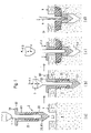
- Figure 1 illustrates an exemplary embodiment of the invention with four consecutive phases (a) to (d) of a first exemplary embodiment of the method disclosed.
- the suture anchor 2 is to be fixated in cancellous bone tissue 8 being situated underneath a cortical bone layer 7, wherein e.g. a blind opening 5.1 reaching through the cortical bone layer 8 only is provided beforehand.
- a similar fixation can be achieved also if no cortical layer is present, wherein the fixation location will have a predefined depth and is situated e.g. underneath a denser layer of cancellous bone in cancellous bone of a lesser density.
- the suture anchor 2 is arranged on the distal end of a vibration tool 1, and it comprises an anchor foot 22 (distal anchor part) and a thermoplastic sleeve 23 (proximal anchor part), wherein the thermoplastic sleeve 23 comprises the material to be liquefied (material having thermoplastic properties) or is preferably made thereof, and wherein a loop of the suture 4 is held in a system 25 of passages and/or grooves (e.g. constituted, as illustrated, by a simple eyelet 85) provided in the anchor foot 22.
- a system 25 of passages and/or grooves e.g. constituted, as illustrated, by a simple eyelet 85
- the vibration tool 1 and the anchor foot 22 comprise an axial channel for accommodation of the K-wire, wherein this channel extends e.g. along the axis of the anchor foot and the eyelet 85 has an eccentric position.
- the suture end portions extend preferably through the thermoplastic sleeve 23 or through the vibration tool 1, which for such purpose may comprise an axial channel at least through its distal end portion. If the suture 4 is to be locked relative to the anchor together with the anchor being fixated, the suture end portions extend preferably on the outside of the thermoplastic sleeve 23, wherein, for preventing damage of the suture during the process of forcing the anchor foot 22 into the hard tissue, axial suture grooves (not shown) may be provided on the thermoplastic sleeve (see also Fig. 4 ). As illustrated in Fig.
- the vibration tool 1 may reach through the whole length of the thermoplastic sleeve 23.
- the anchor foot 22 may reach into or through the thermoplastic sleeve 23 and possibly comprise the means for holding the suture (e.g. an eyelet) in such proximal region.
- Phase (a) of Fig. 1 shows the suture anchor 2 mounted on the distal end of tool 1, the anchor foot 22 being connected to the distal tool end and the thermoplastic sleeve 23 sitting against the proximal face of the anchor foot 22 (or being attached thereto, see Fig. 4 ) and surrounding the distal tool end (or a proximal anchor foot part) loosely.
- connection between the anchor foot 22 and the distal tool end is such that it can transmit a force directed into the hard tissue (pushing force or compressive force) as well as a force directed away from the hard tissue (pulling force or tensile force) to the anchor foot 22, such that vibration is transmitted from the tool to the anchor foot, and such that the tool 1 can be easily disconnected from the anchor foot 22 after completion of the fixation process.
- Suitable connections are e.g. a bayonet coupling, cooperating inner and outer threads or possibly a predetermined breaking point suitable for being broken by rotation of the tool relative to the anchor. Such connections without axial play are able to fully transmit the vibration.
- connection with axial play, in particular bayonet connections with axial play, are possible also but will transmit only half of the vibration wave (hammering effect in the forcing step). If the connection is designed for being able to transmit a rotational force from the tool 1 into the anchor foot 22, the forcing process may be enhanced not only by vibration but also by rotation of the anchor foot 22.
- the device for carrying out the method according to Fig. 1 further comprises a support element 80 with a tube-shaped part 81 fitting into the opening 5.1 and allowing the distal tool end to reach through it.
- the cross section of the tube-shaped part 81 is the same or preferably somewhat smaller than the cross section of the anchor foot 22 such that it is capable of being introduced with no or hardly any force into the hard tissue opening produced by forcing the anchor foot into the hard tissue.
- the support element 80 preferably further comprises a flange-shaped part 82 allowing the support element to sit on the hard tissue surface with the tube-shaped part 81 extending into the opening 5.1.
- the support element may be part of a guide tool (not shown) for guiding the vibration tool and being attached to the vibration source (not shown) to which the proximal end of the vibration tool is coupled or to a housing thereof.
- a guide tool for guiding the vibration tool and being attached to the vibration source (not shown) to which the proximal end of the vibration tool is coupled or to a housing thereof.
- the tube-shaped part 81 of the support element 80 has an axial length which corresponds approximately with the thickness of the cortical bone layer 7 (or the predefined depth).
- the tube-shaped part 81 may be longer or shorter or may be substantially absent (see Fig. 2 ).
- the support element 80 may not comprise a flange-shaped part 82 or the latter may be constituted by a ring whose axial position on the tube-shaped part 81 can be adapted by the surgeon.
- Phase (b) shows the suture anchor after having been forced into the cancellous bone 8 by applying the pushing force F.1 and preferably vibration V to the vibration tool 1, wherein the used vibration may be, as discussed further above, a vibration mode comprising amplitude modulation or pulses.
- the used vibration may be, as discussed further above, a vibration mode comprising amplitude modulation or pulses.
- liquefaction of the material of the thermoplastic sleeve is prevented by using such a vibration mode, but can also be prevented by taking care that the thermoplastic sleeve 23 is not clamped between the support element 80 and the anchor foot 22.
- the anchor foot 22 has reached a sufficient depth in the cancellous bone when the flange-shaped part 82 of the support element 80 is able to be brought into contact with the hard tissue surface 6.
- Phase (c) shows the anchor after the anchoring step which is effected by vibrating the tool 1 (vibration V, if applicable of a different vibration mode than used in the forcing step, base vibration) and applying the pulling force F.2 to it and by counteracting the pulling force F.2 by holding the support element 80 (or a corresponding guide tool, the support element being a part thereof) against the hard tissue surface (force F.3), i.e. applying a compressing force to the thermoplastic sleeve 23 or clamping it between anchor foot 22 and support element 80 respectively.
- thermoplastic sleeve 23 Due to the thermoplastic sleeve 23 being such clamped between the anchor foot 22 and the support element 80 and due to the vibration, the material of the thermoplastic sleeve is at least partly liquefied starting from its proximal and/or distal face, depending e.g. on energy directors being provided to act on these end faces of the thermoplastic sleeve 23, and the liquefied material penetrates the hard tissue surrounding the thermoplastic sleeve 23.
- the support element 80 With the thermoplastic sleeve getting shorter through liquefaction and displacement of the sleeve material, the support element 80 remains held against the hard tissue surface and the anchor foot 22 is moved in the hard tissue in a direction against the hard tissue surface, leaving void the bottom 5.2 of the opening 5 which was established or at least enlarged in the forcing step.
- Phase (d) shows the suture anchor 2 finally fixated, the tool 1 disconnected from the anchor foot 22 and tool 1 and support element 80 being removed from the fixation site.
- Anchorage with the aid of the in situ liquefaction of the material having thermoplastic properties is very little dependent on the quality of the hard tissue, which in an embodiment according to Fig. 1 may even be completely absent (soft tissue or body cavity below the cortical bone layer).
- the liquefied material may or may not penetrate the inner surface of the cortical bone layer and be held in the hard tissue opening 5.1 mainly by the fact of constituting after re-solidification a body which cannot pass through the opening any more.
- the fixation according to the invention is suitable not only for a subcortical fixation in cancellous bone of a reduced mechanical stability but also in absence of cancellous bone e.g. in the medullary cavity of long bones or on a non-accessible side of or beyond a bone plate (fixation by supra-cortical button).
- the suture fixated by the supra-cortical button may be a suture bundle which is used to directly replace a tendon or ligament.
- a pre-tensioned resilient element e.g. pre-tensioned spring
- the resilient element and its pre-tensioning being dimensioned for supplying the clamping force for clamping the thermoplastic sleeve 23 between the anchor foot 22 and the support element 80 and to drive the relative axial movement between the anchor foot 22 and the support element 80 when the thermoplastic sleeve 23 gets shorter.
- Figure 2 illustrates a further exemplary embodiment of the method disclosed, wherein the device (vibration tool 1, anchor foot 22, thermoplastic sleeve 23 and support element 80) is shown after completion of the forcing and anchoring steps but before removal of the tool 1 and the support element 80.
- the method illustrated in Fig. 2 differs from the method illustrated in Fig. 1 only in that it does not result with the proximal face of the thermoplastic sleeve 23 positioned at a predetermined depth below the hard tissue surface (e.g. approximately at the inner surface of the cortical bone layer, but in an anchor fixation in which the proximal face of the thermoplastic sleeve is finally about flush with the bone surface 6.
- Such anchorage is achieved by using a support element 80 with substantially no tube-shaped part and preferably by controlling the anchoring step such that the material of the thermoplastic sleeve 23 is mainly liquefied starting from the distal end thereof.
- the suture which is not shown in Fig. 2 extends preferably through the thermoplastic sleeve 23 and the support element 80 and is therewith safeguarded against damage through friction on the bone of the mouth of the bone opening by the thermoplastic sleeve 23.
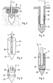
- FIGs 3 to 6 show further exemplified embodiments of anchors or devices comprising anchor 2, tool 1 and possibly support element 80, which devices are suitable for the methods as illustrated in Figs. 1 or 2 , wherein the features of these anchors and devices and of the anchor and device shown in Figs. 1 and 2 can also be used in combinations different from the shown combinations.
- the device according to Fig. 3 is equipped for liquefaction of the material of the thermoplastic sleeve 23 starting from the proximal sleeve face as preferred in the method according to Fig. 1 .
- This is effected by the distal face of the support element 80 tapering to a relatively sharp inner edge 83, the sharp edge serving as energy director and the taper enhancing the displacement of the liquefied material radially outwards and into the bone wall of the bone opening.
- Liquefaction at the distal face of the thermoplastic sleeve may be prevented by not providing energy directors there (contact area between anchor foot 22 and thermoplastic sleeve 23 as large and as even as possible) and/or by fastening the thermoplastic sleeve 23 to the anchor foot 22.
- thermoplastic sleeve 23 sitting in a corresponding bush of the anchor foot 22 and being retained therein e.g. by a force fit or friction fit.
- the same effect may also be achieved by e.g. gluing, welding or screwing the two anchor parts together or by manufacturing the anchor foot 22 and the thermoplastic sleeve 23 as one piece (see also Fig. 4 ), e.g. from the same material which, in the region of the distal anchor foot end, may be strengthened for the forcing step by a suitable filler or a metal insert.
- Fig. 3 further shows the vibration tool equipped with a stop 1.1 for limiting the depth to which the anchor foot can be forced into the bone tissue.
- This stop 1.1. is e.g. constituted by a step separating a distal tool portion with a cross section adapted to the axial channel of the thermoplastic sleeve 23 from a proximal tool portion with a larger cross section not able to be introduced into the thermoplastic sleeve.
- the vibration mode for the forcing step can be chosen accordingly, as discussed further above.
- the anchor according to Fig 3 may comprise an axial channel for accommodation of a K-wire, wherein the anchor needs to be designed such that on threading the anchor along the K-wire the wire does not interfere with the suture being threaded through the anchor foot or extending therefrom.
- Fig. 4 shows a one-piece anchor 2 with portions constituting anchor foot 22 and thermoplastic sleeve 23.
- a loop of the suture 4 is retained in an eyelet 85 (or other suitable system of passages and/or grooves) provided in the anchor foot portion 22.
- eyelet 85 or other suitable system of passages and/or grooves
- axial suture grooves 86 may be provided in the thermoplastic sleeve portion 23.
- the anchor according to Fig. 4 may be made of one only material e.g. of a suitably filled polylactide material, wherein the anchor foot portion 22 may be filled to a higher degree than the thermoplastic sleeve portion 23.
- the anchor foot portion is made of a different material suitable for the forcing step (for examples see further above) than the material having thermoplastic properties of the thermoplastic sleeve portion.
- the arrangement of the suture 4 may make it possible for the suture to remain slideable relative to the anchor during the forcing and possibly after the anchoring step or for locking the suture relative to the anchor during the anchoring step.
- Fig. 5 shows an anchor foot 22 which, for retaining the suture 4, comprises an eyelet 85 and a pair of axial suture grooves 86 extending from the eyelet to the proximal face of the anchor foot (system of passages and/or grooves) from where the suture 4 may extend inside the thermoplastic sleeve (not shown) or along its outer surface where suture grooves may be provided (as shown in Fig. 4 ) or not.
- the anchor foot 22 For attachment to a distal tool end, the anchor foot 22 according to Fig. 5 comprises a threaded post adapted to a corresponding inner thread provided on the distal tool face (not shown).
- Fig. 6 shows an anchor 2 equipped for retaining a suture knot 4.1 in a recess provided at an entrance to the eyelet 85, the suture 4 extending from the suture knot 4.1 through the eyelet 85, in a suture groove 86 to the proximal face of the anchor foot 22 and then along a slot 87 (or groove) extending from the distal to the proximal face of the thermoplastic sleeve 23.
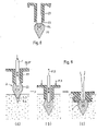
- Figure 7 illustrates a further exemplary embodiment of the method disclosed with four consecutive phases (a) to (d) of a fixation of a headed anchor 2, wherein the headed anchor is e.g. suitable for being used for fixating a soft tissue 90 (e.g. ligament or tendon) or a corresponding prosthetic element to hard tissue (e.g. bone).
- the soft tissue 90 is illustrated to be fixated to bone tissue which e.g. does not have a cortical layer (decorticated bone tissue, i.e. substantially cancellous bone tissue 8 only) or has a cortical layer through which the headed anchor can be forced, the distal anchor end e.g. being shaped like a bone awl.
- the anchor 2 again comprises an anchor foot 22 equipped for the forcing step as described further above in connection with Figs. 1 to 6 and a thermoplastic sleeve 23, wherein the thermoplastic sleeve 23 carries a flange-shaped proximal portion constituting the anchor head 91 and further constituting an equivalent to the flange-shaped part of the support element according to Fig. 1 in the anchoring step.
- the anchor head 91 is preferably made of the same material as the thermoplastic sleeve 23 but may also be made of a different material.
- the anchor head 91 may, in a per se known manner, comprise distal protrusions 92 which are pressed into the soft tissue 90 during the fixation process.
- phase (b) the anchor 2 is shown when forced into the hard tissue to a sufficient depth which is achieved when the anchor head 91 is able to press the soft tissue 90 against the bone surface 6 and the soft tissue 90 is compressed such that the distal protrusions 92 of the anchor head 91 are pressed into the soft tissue or even through it and possibly into the bone surface 6.
- Phase (d) shows the headed anchor 2 finally anchored in the cancellous bone tissue 8 and the soft tissue 90 therewith safely attached to the bone tissue.
- the anchor 2 according to Fig. 7 comprises means for retaining a suture as illustrated in the previous Figs. and in Fig. 8 , it can of course also be used for fixating a suture relative to bone tissue instead of for fixating a soft tissue relative to bone tissue.
- thermoplastic sleeve 23 it is necessary, in the embodiment as illustrated in Fig. 2 it is preferred that the liquefaction process starts at the distal end of the thermoplastic sleeve and therefore it is advantageous to equip the contact area between the distal face of the thermoplastic sleeve 23 and the proximal face of the anchor foot 22 with energy directors.
- Figure 8 shows a preferred embodiment of such energy directors which have the form of the proximal face of the anchor foot 22 tapering inwards to form a relatively sharp edge 83 adapted to the cross section of the axial channel through the thermoplastic sleeve 23, wherein the relatively sharp edge 83 constitutes the energy directors and the taper enhances displacement of the liquefied material radially outward and therewith into the bone tissue surrounding the anchor (re-enforcement or augmentation of the tissue which finally surrounds the anchor foot). Furthermore, Fig.
- phase (c) which shows a similar anchor in an anchored configuration, the named design of the proximal anchor foot face further helps to stabilize the anchor foot against loads which act at an angle to the anchor axis and which, especially in hard tissue of little mechanical resistance, may otherwise be able to tilt or laterally dislocate the anchor foot.
- Figure 9 illustrates a further exemplary embodiment of the method disclosed, wherein the anchor may be of a similar kind as the anchor according to Fig. 8 (suture only shown in phase (c)) and may comprise a head or none, or may be a headed anchor.
- the anchor foot is forced into the bone tissue in the forcing step and remains in the same position during the anchoring step, the material of the thermoplastic sleeve preferably being liquefied starting from the distal end of the thermoplastic sleeve and, depending on the anchor design, the support element 80 or the anchor head 91 being moved towards the stationary anchor foot 22 and the force F.3 used for such movement being counteracted preferably by the tensile force F.2 applied to the vibration tool 1 and/or possibly by the bone tissue in contact with the distal face of the anchor foot.
- Fig. 9 shows the method in three consecutive phases (a) to (c).
- Phase (a) shows the device for carrying the method positioned in a pilot bore 5.4 being provided in the bone tissue.
- the anchor 2 comprises an anchor foot 22 suitable for being forced into hard tissue and a thermoplastic sleeve 23, wherein the thermoplastic sleeve 23 may comprise a flange-shaped proximal portion (anchor head 91) or the device further comprises a support element 80.
- the anchor foot 22 is fastened to the distal end of the vibration tool 1 and the thermoplastic sleeve 23 sits loosely on the proximal face of the anchor foot 22.
- Phase (b) shows the anchor after the forcing step in which the anchor is forced into the pilot bore 5.4 with the aid of a pushing force F.1 acting through the vibration tool 1 on the anchor foot 22, whereby the pilot bore 5.4 is enlarged regarding cross section and/or depth.
- the anchor head 91 or the support element 80 is moved towards the anchor foot 22 with the aid of force F.3 which is applied to the anchor head or the support element and which is counteracted by the pulling force F.2 acting on vibration tool 1 and/or by the bone tissue in the area of the distal face of the anchor foot, wherein these forces are dimensioned such that the anchor foot remains substantially stationary relative to the bone tissue.
- Phase (c) shows the fixated anchor after completion of the forcing step and the anchoring step and after removal of the vibration tool 1.
- Figure 10 shows an anchor 2 suitable for the method disclosed, the anchor comprising an anchor foot 22 which is equipped for being forced into hard tissue by punching through the hard tissue, the punching process preferably being assisted with vibrational energy coupled into the anchor foot 22 as above described.
- the anchor foot as shown in Fig. 10 is suitable for all embodiments of the method described above. It is particularly suited for being forced through a cortical bone layer 7 into tissue underneath the cortical bone layer which can be compacted to accommodate the punched-out piece of the cortical bone layer (e.g. cancellous bone tissue 8) or into a cavity or soft tissue underneath the cortical bone layer 7.
- Fig. 10 shows a method embodiment similar to the method illustrated in Fig.
- the anchor foot 22 can be used in combination with any system of passages and/or grooves for retaining a suture and/or in a headed anchor as described above.
- the anchor foot 22 according to Fig. 10 comprises a distal end in the form of a hollow cylinder (circular or non-circular) having a thin wall and a sharpened distal face, is mounted for the punching (forcing step) and for the anchoring step on the distal end of the vibration tool 1, wherein the thermoplastic sleeve 23 sits between the anchor foot 22 and a counter element 80.
- the anchor foot 22 is positioned e.g. on the cortical bone layer 7 in the location in which a sub-cortical fixation of the anchor foot 22 is to be achieved (phase (a)).
- the anchor foot 22 With the aid of the tool 1 and vibration transmitted through the tool 1 into the anchor foot 22, the anchor foot 22 is forced into the bone tissue punching out a piece thereof and displacing it further into the cancellous bone tissue 8 situated underneath the cortical bone layer 7 and at the same time compacting the cancellous bone tissue 8 (phase (b)).
- the anchor foot 22 has reached a sufficient depth in the bone tissue, when the liquefaction location (e.g. the interface between the distal face of the counter element 80 and the proximal face of the thermoplastic sleeve 23) has passed the cortical bone layer 7.
- the force acting on the tool 1 is reversed (from pushing to pulling action) and while the thermoplastic sleeve 23 is at least partly liquefied the anchor foot 22 is pulled against the cortical bone layer, the liquefied sleeve material anchoring the anchor foot 22 on the inside of the cortical bone layer 7 (re-solidified material 40) or forming a body 44 which cannot pass the opening punched through the cortical bone layer.
- suture anchors suitable for soft tissue attachment to hard tissue.
- the sutures may be safeguarded against damage by heat dissipating from the material having thermoplastic properties when liquefied, by being soaked with liquid (water or saline solution) preferably before being threaded through the suture anchor or a part thereof or before being positioned in the hard tissue opening and necessarily before liquefaction of the material having thermoplastic properties.
Landscapes
- Health & Medical Sciences (AREA)
- Life Sciences & Earth Sciences (AREA)
- Surgery (AREA)
- Animal Behavior & Ethology (AREA)
- General Health & Medical Sciences (AREA)
- Engineering & Computer Science (AREA)
- Biomedical Technology (AREA)
- Heart & Thoracic Surgery (AREA)
- Veterinary Medicine (AREA)
- Public Health (AREA)
- Rheumatology (AREA)
- Medical Informatics (AREA)
- Molecular Biology (AREA)
- Nuclear Medicine, Radiotherapy & Molecular Imaging (AREA)
- Orthopedic Medicine & Surgery (AREA)
- Rehabilitation Therapy (AREA)
- Cardiology (AREA)
- Oral & Maxillofacial Surgery (AREA)
- Transplantation (AREA)
- Vascular Medicine (AREA)
- Surgical Instruments (AREA)
Applications Claiming Priority (3)
| Application Number | Priority Date | Filing Date | Title |
|---|---|---|---|
| US201161437227P | 2011-01-28 | 2011-01-28 | |
| PCT/CH2012/000017 WO2012100358A1 (en) | 2011-01-28 | 2012-01-26 | Device and method for fixating a suture anchor with a suture or a headed anchor in hard tissue |
| EP12705223.1A EP2667789B1 (en) | 2011-01-28 | 2012-01-26 | Device for fixating a suture anchor with a suture or a headed anchor in hard tissue |
Related Parent Applications (2)
| Application Number | Title | Priority Date | Filing Date |
|---|---|---|---|
| EP12705223.1A Division-Into EP2667789B1 (en) | 2011-01-28 | 2012-01-26 | Device for fixating a suture anchor with a suture or a headed anchor in hard tissue |
| EP12705223.1A Division EP2667789B1 (en) | 2011-01-28 | 2012-01-26 | Device for fixating a suture anchor with a suture or a headed anchor in hard tissue |
Publications (2)
| Publication Number | Publication Date |
|---|---|
| EP3632341A1 EP3632341A1 (en) | 2020-04-08 |
| EP3632341B1 true EP3632341B1 (en) | 2022-11-09 |
Family
ID=46584464
Family Applications (2)
| Application Number | Title | Priority Date | Filing Date |
|---|---|---|---|
| EP12705223.1A Active EP2667789B1 (en) | 2011-01-28 | 2012-01-26 | Device for fixating a suture anchor with a suture or a headed anchor in hard tissue |
| EP19210701.9A Active EP3632341B1 (en) | 2011-01-28 | 2012-01-26 | Device for fixating a suture anchor with a suture or a headed anchor in hard tissue |
Family Applications Before (1)
| Application Number | Title | Priority Date | Filing Date |
|---|---|---|---|
| EP12705223.1A Active EP2667789B1 (en) | 2011-01-28 | 2012-01-26 | Device for fixating a suture anchor with a suture or a headed anchor in hard tissue |
Country Status (10)
| Country | Link |
|---|---|
| US (2) | US8834542B2 (ru) |
| EP (2) | EP2667789B1 (ru) |
| JP (1) | JP6120776B2 (ru) |
| KR (2) | KR101998429B1 (ru) |
| CN (1) | CN103338711B (ru) |
| BR (1) | BR112013019027B1 (ru) |
| CA (1) | CA2821360C (ru) |
| IL (1) | IL227074A (ru) |
| RU (1) | RU2602326C2 (ru) |
| WO (1) | WO2012100358A1 (ru) |
Families Citing this family (23)
| Publication number | Priority date | Publication date | Assignee | Title |
|---|---|---|---|---|
| US7094251B2 (en) | 2002-08-27 | 2006-08-22 | Marctec, Llc. | Apparatus and method for securing a suture |
| US9089323B2 (en) | 2005-02-22 | 2015-07-28 | P Tech, Llc | Device and method for securing body tissue |
| US11253296B2 (en) | 2006-02-07 | 2022-02-22 | P Tech, Llc | Methods and devices for intracorporeal bonding of implants with thermal energy |
| US7967820B2 (en) * | 2006-02-07 | 2011-06-28 | P Tech, Llc. | Methods and devices for trauma welding |
| US11278331B2 (en) | 2006-02-07 | 2022-03-22 | P Tech Llc | Method and devices for intracorporeal bonding of implants with thermal energy |
| US8496657B2 (en) * | 2006-02-07 | 2013-07-30 | P Tech, Llc. | Methods for utilizing vibratory energy to weld, stake and/or remove implants |
| US11246638B2 (en) | 2006-05-03 | 2022-02-15 | P Tech, Llc | Methods and devices for utilizing bondable materials |
| WO2010099222A1 (en) | 2009-02-24 | 2010-09-02 | P Tech, Llc | Methods and devices for utilizing bondable materials |
| KR101691251B1 (ko) * | 2009-11-09 | 2016-12-29 | 스피네벨딩 아게 | 의료 장치, 기구 및 수술 방법 |
| CN103052360B (zh) * | 2010-09-08 | 2017-08-29 | 斯恩蒂斯有限公司 | 具有镁芯的固定装置 |
| JP6108297B2 (ja) * | 2012-02-02 | 2017-04-05 | 国立大学法人福井大学 | 解剖体等の縫合方法、この方法に用いられる縫合糸、穿刺針及び穿刺針器 |
| RU2495640C1 (ru) * | 2012-07-23 | 2013-10-20 | Государственное автономное учреждение здравоохранения "Республиканская клиническая больница Министерства здравоохранения Республики Татарстан" | Способ сухожильного эндопротезирования глубокого сгибателя пальца кисти |
| US9901333B2 (en) | 2013-03-13 | 2018-02-27 | DePuy Synthes Products, Inc. | Soft tissue fixation system |
| US9913637B2 (en) | 2013-03-13 | 2018-03-13 | DePuy Synthes Products, Inc. | Soft tissue fixation system |
| EP2967544B1 (en) * | 2013-03-13 | 2019-04-24 | DePuy Synthes Products, Inc. | Soft tissue fixation system |
| US9763674B2 (en) * | 2013-12-26 | 2017-09-19 | Ethicon Llc | Ultrasonic bone cutting instrument |
| BR112017020595B1 (pt) * | 2015-06-11 | 2022-05-03 | Woodwelding Ag | Métodos de ancoragem e aparelho para ancorar um conector |
| US10646345B2 (en) | 2017-06-02 | 2020-05-12 | Howmedica Osteonics Corp. | Implant with hole having porous structure for soft tissue fixation |
| US11224465B2 (en) * | 2018-12-04 | 2022-01-18 | Spinewelding Ag | Surgical methods for the treatment of spinal stenosis |
| US20200325924A1 (en) * | 2019-04-12 | 2020-10-15 | Black & Decker Inc. | Cast-in place anchor with multi-use jaws and removable nose-piece |
| CN109893189A (zh) * | 2019-04-16 | 2019-06-18 | 江苏尚美医疗器械有限公司 | 一种用于相对硬组织固定缝线的线锚钉固定装置 |
| KR102322486B1 (ko) * | 2020-01-28 | 2021-11-05 | 주식회사 바이원 | 올인원 봉합 앵커. |
| CN117206402B (zh) * | 2023-11-07 | 2024-01-05 | 烟台立源力机械零部件有限公司 | 一种金属器械加工用连续冲压装置 |
Family Cites Families (87)
| Publication number | Priority date | Publication date | Assignee | Title |
|---|---|---|---|---|
| SU1159567A1 (ru) * | 1984-01-02 | 1985-06-07 | Новокузнецкий Государственный Ордена Трудового Красного Знамени Институт Усовершенствования Врачей | Ножка эндопротеза |
| US5632748A (en) * | 1993-06-14 | 1997-05-27 | Linvatec Corporation | Endosteal anchoring device for urging a ligament against a bone surface |
| US5522844A (en) | 1993-06-22 | 1996-06-04 | Johnson; Lanny L. | Suture anchor, suture anchor installation device and method for attaching a suture to a bone |
| US5454811A (en) * | 1993-11-08 | 1995-10-03 | Smith & Nephew Dyonics, Inc. | Cam lock orthopedic fixation screw and method |
| US5464427A (en) | 1994-10-04 | 1995-11-07 | Synthes (U.S.A.) | Expanding suture anchor |
| US6569188B2 (en) | 1996-08-05 | 2003-05-27 | Arthrex, Inc. | Hex drive bioabsorbable tissue anchor |
| US6319270B1 (en) | 1996-08-05 | 2001-11-20 | Arthrex, Inc. | Headed bioabsorbable tissue anchor |
| US6117162A (en) | 1996-08-05 | 2000-09-12 | Arthrex, Inc. | Corkscrew suture anchor |
| US5733307A (en) | 1996-09-17 | 1998-03-31 | Amei Technologies, Inc. | Bone anchor having a suture trough |
| US5709708A (en) | 1997-01-31 | 1998-01-20 | Thal; Raymond | Captured-loop knotless suture anchor assembly |
| US6024758A (en) | 1998-02-23 | 2000-02-15 | Thal; Raymond | Two-part captured-loop knotless suture anchor assembly |
| US5941901A (en) * | 1998-04-16 | 1999-08-24 | Axya Medical, Inc. | Bondable expansion plug for soft tissue fixation |
| US5993458A (en) | 1998-06-25 | 1999-11-30 | Ethicon, Inc. | Method of ultrasonically embedding bone anchors |
| US7226469B2 (en) | 1999-02-02 | 2007-06-05 | Arthrex, Inc. | Insert molded suture anchor |
| US20060161159A1 (en) | 1999-02-02 | 2006-07-20 | Dreyfuss Peter J | PEEK ribbed suture anchor |
| EP1031321B1 (en) | 1999-02-02 | 2008-01-09 | Arthrex Inc | Bioabsorbable tissue tack with oval-shaped head |
| US9521999B2 (en) | 2005-09-13 | 2016-12-20 | Arthrex, Inc. | Fully-threaded bioabsorbable suture anchor |
| US8343186B2 (en) | 2004-04-06 | 2013-01-01 | Arthrex, Inc. | Fully threaded suture anchor with transverse anchor pin |
| US7211088B2 (en) | 1999-02-02 | 2007-05-01 | Arthrex, Inc. | Bioabsorbable tissue tack with oval-shaped head and method of tissue fixation using the same |
| US8821541B2 (en) | 1999-02-02 | 2014-09-02 | Arthrex, Inc. | Suture anchor with insert-molded rigid member |
| US6409730B1 (en) * | 2000-05-31 | 2002-06-25 | Synthes (Usa) | Humeral spiral blade |
| WO2001097677A2 (en) | 2000-06-22 | 2001-12-27 | Arthrex, Inc. | Graft fixation using a screw or plug against suture or tissue |
| US7329272B2 (en) | 2000-06-22 | 2008-02-12 | Arthrex, Inc. | Graft fixation using a plug against suture |
| US7144414B2 (en) | 2000-06-27 | 2006-12-05 | Smith & Nephew, Inc. | Surgical procedures and instruments |
| US6620185B1 (en) | 2000-06-27 | 2003-09-16 | Smith & Nephew, Inc. | Surgical procedures and instruments |
| CA2439533C (en) | 2001-03-02 | 2009-11-03 | Woodwelding Ag | Implants, device and method for joining tissue parts |
| US6508830B2 (en) | 2001-04-30 | 2003-01-21 | Musculoskeletal Transplant Foundation | Suture anchor |
| EP1262152A1 (fr) | 2001-05-25 | 2002-12-04 | Ecole d'ingénieurs | Instruments de façonnage par ultrasons |
| US6641597B2 (en) | 2001-05-25 | 2003-11-04 | Arthrex, Inc. | Interference fit knotless suture anchor fixation |
| US7008226B2 (en) | 2002-08-23 | 2006-03-07 | Woodwelding Ag | Implant, in particular a dental implant |
| US7442202B2 (en) | 2002-08-26 | 2008-10-28 | Arthrex, Inc. | Suture anchor attached to tissue-fixation disk without top knot |
| US7713285B1 (en) | 2003-07-02 | 2010-05-11 | Biomet Sports Medicine, Llc | Method and apparatus for suture anchors with a vertical eyelet |
| US7678134B2 (en) | 2003-10-10 | 2010-03-16 | Arthrex, Inc. | Knotless anchor for tissue repair |
| US7846183B2 (en) | 2004-02-06 | 2010-12-07 | Spinal Elements, Inc. | Vertebral facet joint prosthesis and method of fixation |
| CA2556963A1 (en) | 2004-02-20 | 2005-09-01 | Woodwelding Ag | Implant that can be implanted in osseous tissue, method for producing said implant and corresponding implant |
| US7604643B2 (en) | 2004-04-06 | 2009-10-20 | Synthes Usa, Llc | Adjustable tool for cannulated fasteners |
| US8579940B2 (en) | 2004-04-06 | 2013-11-12 | Arthrex, Inc. | Suture anchor with apertures at tip |
| US9504583B2 (en) | 2004-06-10 | 2016-11-29 | Spinal Elements, Inc. | Implant and method for facet immobilization |
| US8361113B2 (en) | 2006-02-03 | 2013-01-29 | Biomet Sports Medicine, Llc | Method and apparatus for coupling soft tissue to a bone |
| US8298262B2 (en) | 2006-02-03 | 2012-10-30 | Biomet Sports Medicine, Llc | Method for tissue fixation |
| US20090192546A1 (en) | 2005-03-30 | 2009-07-30 | Reinhold Schmieding | Fenestrated suture anchor and method for knotless fixation of tissue |
| US20080208253A1 (en) | 2006-05-18 | 2008-08-28 | Dreyfuss Peter J | Self-punching swivel anchor and method for knotless fixation of tissue |
| US20090187216A1 (en) | 2006-05-18 | 2009-07-23 | Arthrex, Inc. | Fenestrated swivel anchor for knotless fixation of tissue |
| US7695495B2 (en) | 2005-12-13 | 2010-04-13 | Arthrex, Inc. | Peek threaded suture anchor |
| US8202295B2 (en) | 2006-07-20 | 2012-06-19 | Kaplan Lee D | Surgical instruments |
| EP2517663B1 (en) | 2006-08-22 | 2017-06-14 | Mitsubishi Electric Corporation | Implant material and implant-material fabrication method |
| US20080097491A1 (en) | 2006-08-28 | 2008-04-24 | Fred Gobel | Tissue to tissue anchoring device and method of using the same |
| WO2008034277A2 (en) | 2006-09-20 | 2008-03-27 | Woodwelding Ag | Implant, implantation device, implantation method |
| ES2364681T3 (es) | 2006-09-20 | 2011-09-12 | Woodwelding Ag | Dispositivo para implante en tejido humano o animal. |
| US20100179573A1 (en) | 2006-10-31 | 2010-07-15 | Core Essence Orthopaedics, Llc | Medical device and procedure for attaching tissue to bone |
| JP5272255B2 (ja) | 2006-10-31 | 2013-08-28 | オーソノーブル インコーポレイテッド | 組織を骨に取り付けるための医療器具および処置 |
| US8083769B2 (en) | 2006-11-01 | 2011-12-27 | Depuy Mitek, Inc. | Wired sutures |
| US20080109038A1 (en) | 2006-11-08 | 2008-05-08 | Musculoskeletal Transplant Foundation | Threaded suture anchor and inserter device |
| WO2008128367A1 (en) | 2007-04-20 | 2008-10-30 | Woodwelding Ag | Method for fastening an implant to bone tissue and corresponding implant system |
| EP1987784B1 (en) | 2007-04-30 | 2011-12-14 | Stryker Trauma GmbH | Device for preparing a non-rotational-symmetric recess in a bone |
| US8343189B2 (en) | 2007-09-25 | 2013-01-01 | Zyga Technology, Inc. | Method and apparatus for facet joint stabilization |
| EP2205185B1 (en) * | 2007-10-30 | 2014-06-18 | Woodwelding AG | Device for producing an anchorage in human or animal tissue |
| US20090171394A1 (en) | 2007-12-18 | 2009-07-02 | Abdou M S | Devices And Methods For The Treatment Of Facet Joint Disease |
| PL2249710T3 (pl) * | 2008-03-03 | 2016-12-30 | Urządzenie do kotwienia nitki w tkance | |
| US8439936B2 (en) | 2008-03-06 | 2013-05-14 | Zone 2 Surgical, Inc. | Device and method for tendon, ligament or soft tissue repair |
| CN102083379B (zh) | 2008-05-01 | 2015-07-08 | 伍德韦尔丁公司 | 在组织中建立锚固的装置和方法 |
| US8777990B2 (en) | 2008-09-08 | 2014-07-15 | Howmedica Osteonics Corp. | Knotless suture anchor for soft tissue repair and method of use |
| JP5567023B2 (ja) * | 2008-10-23 | 2014-08-06 | ダブリュ・ダブリュ・テクノロジー・アクチェンゲゼルシャフト | 対象物を硬組織に固定するための増強装置 |
| EP2221014B1 (en) | 2009-02-23 | 2015-05-20 | Inion Oy | Implant, implantation tool and kit |
| EP2416735B1 (en) | 2009-04-06 | 2013-07-17 | Smith & Nephew, Inc. | Tissue graft anchor |
| EP2238914B1 (en) | 2009-04-10 | 2015-05-20 | Arthrex, Inc. | Twist-in suture anchor |
| WO2010132310A1 (en) * | 2009-05-12 | 2010-11-18 | Foundry Newco Xi, Inc. | Methods and devices to treat diseased or injured musculoskeletal tissue |
| US9179905B2 (en) | 2009-07-17 | 2015-11-10 | Pivot Medical, Inc. | Method and apparatus for re-attaching the labrum to the acetabulum, including the provision and use of a novel suture anchor system |
| US8834553B2 (en) | 2009-09-11 | 2014-09-16 | Gi Dynamics, Inc. | Anchors with biodegradable constraints |
| EP2498686B1 (en) | 2009-11-10 | 2024-01-10 | Smith & Nephew, Inc. | Tissue repair devices |
| JP2013525083A (ja) | 2010-05-06 | 2013-06-20 | ジンテス ゲゼルシャフト ミット ベシュレンクテル ハフツング | 軟組織欠陥装置及び関連する方法 |
| WO2012006161A2 (en) | 2010-06-29 | 2012-01-12 | Synthes Usa, Llc | Insertion instrument for anchor assembly |
| US8460340B2 (en) | 2010-08-30 | 2013-06-11 | Depuy Mitek, Llc | Knotless suture anchor |
| CN103052360B (zh) * | 2010-09-08 | 2017-08-29 | 斯恩蒂斯有限公司 | 具有镁芯的固定装置 |
| FR2965168A1 (fr) | 2010-09-23 | 2012-03-30 | Tornier Inc | Composant d'implant de suture et dispositif d'implant de suture comprenant un tel composant |
| US9775596B2 (en) | 2010-09-17 | 2017-10-03 | DePuy Synthes Products, Inc. | Device for anchoring a suture |
| WO2012096786A1 (en) | 2011-01-14 | 2012-07-19 | Synthes Usa, Llc | Elongated fixation element |
| EP2486856B1 (en) | 2011-02-09 | 2014-07-09 | Arthrex, Inc. | Bone anchor for scapholunate construct |
| US8591545B2 (en) | 2011-03-25 | 2013-11-26 | Smith & Nephew, Inc. | Flat suture anchor |
| CA2840186A1 (en) | 2011-06-23 | 2012-12-27 | DePuy Synthes Products, LLC | Suture anchor system and method |
| US8916004B2 (en) | 2011-06-29 | 2014-12-23 | Medtronic, Inc. | Thermal nitriding process for components of implantable medical devices |
| CA2839629A1 (en) | 2011-06-29 | 2013-01-03 | Pivot Medical, Inc. | Method and apparatus for re-attaching the labrum to the acetabulum, including the provision and use of a novel suture anchor system |
| US20130035721A1 (en) | 2011-08-04 | 2013-02-07 | John Eric Brunelle | Surgical anchor |
| US9107653B2 (en) | 2011-09-22 | 2015-08-18 | Arthrex, Inc. | Tensionable knotless anchors with splice and methods of tissue repair |
| US8535350B2 (en) | 2011-09-28 | 2013-09-17 | Depuy Mitek, Llc | Knotless suture anchor |
| US9119678B2 (en) | 2011-11-01 | 2015-09-01 | Synergy Disc Replacement Inc. | Facet fixation systems |
| US9615856B2 (en) | 2011-11-01 | 2017-04-11 | Imds Llc | Sacroiliac fusion cage |
-
2012
- 2012-01-26 JP JP2013550720A patent/JP6120776B2/ja not_active Expired - Fee Related
- 2012-01-26 CA CA2821360A patent/CA2821360C/en not_active Expired - Fee Related
- 2012-01-26 WO PCT/CH2012/000017 patent/WO2012100358A1/en active Application Filing
- 2012-01-26 EP EP12705223.1A patent/EP2667789B1/en active Active
- 2012-01-26 RU RU2013138870/14A patent/RU2602326C2/ru active
- 2012-01-26 US US13/358,798 patent/US8834542B2/en active Active
- 2012-01-26 KR KR1020137021482A patent/KR101998429B1/ko active IP Right Grant
- 2012-01-26 EP EP19210701.9A patent/EP3632341B1/en active Active
- 2012-01-26 KR KR1020197018347A patent/KR20190079691A/ko not_active IP Right Cessation
- 2012-01-26 BR BR112013019027-2A patent/BR112013019027B1/pt not_active IP Right Cessation
- 2012-01-26 CN CN201280006485.4A patent/CN103338711B/zh not_active Expired - Fee Related
-
2013
- 2013-06-20 IL IL227074A patent/IL227074A/en active IP Right Grant
-
2014
- 2014-08-25 US US14/467,411 patent/US9808235B2/en active Active
Also Published As
| Publication number | Publication date |
|---|---|
| EP2667789B1 (en) | 2020-01-01 |
| CN103338711B (zh) | 2017-04-05 |
| CA2821360A1 (en) | 2012-08-02 |
| US20120197316A1 (en) | 2012-08-02 |
| WO2012100358A1 (en) | 2012-08-02 |
| US20140364908A1 (en) | 2014-12-11 |
| BR112013019027A2 (pt) | 2016-10-04 |
| JP6120776B2 (ja) | 2017-04-26 |
| US9808235B2 (en) | 2017-11-07 |
| KR20190079691A (ko) | 2019-07-05 |
| JP2014510554A (ja) | 2014-05-01 |
| KR20140006882A (ko) | 2014-01-16 |
| BR112013019027B1 (pt) | 2021-11-23 |
| CN103338711A (zh) | 2013-10-02 |
| CA2821360C (en) | 2019-10-22 |
| KR101998429B1 (ko) | 2019-07-09 |
| RU2013138870A (ru) | 2015-03-10 |
| US8834542B2 (en) | 2014-09-16 |
| RU2602326C2 (ru) | 2016-11-20 |
| EP3632341A1 (en) | 2020-04-08 |
| IL227074A (en) | 2016-09-29 |
| EP2667789A1 (en) | 2013-12-04 |
Similar Documents
| Publication | Publication Date | Title |
|---|---|---|
| US10987096B2 (en) | Device and method for fixating a suture anchor with a suture or a headed anchor in hard tissue | |
| US9808235B2 (en) | Device and method for fixating a suture anchor with a suture or a headed anchor in hard tissue | |
| EP2667790B1 (en) | Sytstem for fixating a suture anchor with a suture in hard tissue |
Legal Events
| Date | Code | Title | Description |
|---|---|---|---|
| PUAI | Public reference made under article 153(3) epc to a published international application that has entered the european phase |
Free format text: ORIGINAL CODE: 0009012 |
|
| STAA | Information on the status of an ep patent application or granted ep patent |
Free format text: STATUS: THE APPLICATION HAS BEEN PUBLISHED |
|
| AC | Divisional application: reference to earlier application |
Ref document number: 2667789 Country of ref document: EP Kind code of ref document: P |
|
| AK | Designated contracting states |
Kind code of ref document: A1 Designated state(s): AL AT BE BG CH CY CZ DE DK EE ES FI FR GB GR HR HU IE IS IT LI LT LU LV MC MK MT NL NO PL PT RO RS SE SI SK SM TR |
|
| STAA | Information on the status of an ep patent application or granted ep patent |
Free format text: STATUS: REQUEST FOR EXAMINATION WAS MADE |
|
| 17P | Request for examination filed |
Effective date: 20200929 |
|
| RBV | Designated contracting states (corrected) |
Designated state(s): AL AT BE BG CH CY CZ DE DK EE ES FI FR GB GR HR HU IE IS IT LI LT LU LV MC MK MT NL NO PL PT RO RS SE SI SK SM TR |
|
| GRAP | Despatch of communication of intention to grant a patent |
Free format text: ORIGINAL CODE: EPIDOSNIGR1 |
|
| STAA | Information on the status of an ep patent application or granted ep patent |
Free format text: STATUS: GRANT OF PATENT IS INTENDED |
|
| RIC1 | Information provided on ipc code assigned before grant |
Ipc: A61B 17/00 20060101ALN20220516BHEP Ipc: A61B 17/04 20060101AFI20220516BHEP |
|
| INTG | Intention to grant announced |
Effective date: 20220602 |
|
| GRAS | Grant fee paid |
Free format text: ORIGINAL CODE: EPIDOSNIGR3 |
|
| GRAA | (expected) grant |
Free format text: ORIGINAL CODE: 0009210 |
|
| STAA | Information on the status of an ep patent application or granted ep patent |
Free format text: STATUS: THE PATENT HAS BEEN GRANTED |
|
| AC | Divisional application: reference to earlier application |
Ref document number: 2667789 Country of ref document: EP Kind code of ref document: P |
|
| AK | Designated contracting states |
Kind code of ref document: B1 Designated state(s): AL AT BE BG CH CY CZ DE DK EE ES FI FR GB GR HR HU IE IS IT LI LT LU LV MC MK MT NL NO PL PT RO RS SE SI SK SM TR |
|
| REG | Reference to a national code |
Ref country code: GB Ref legal event code: FG4D |
|
| REG | Reference to a national code |
Ref country code: CH Ref legal event code: EP Ref country code: AT Ref legal event code: REF Ref document number: 1529841 Country of ref document: AT Kind code of ref document: T Effective date: 20221115 |
|
| REG | Reference to a national code |
Ref country code: DE Ref legal event code: R096 Ref document number: 602012079001 Country of ref document: DE |
|
| REG | Reference to a national code |
Ref country code: IE Ref legal event code: FG4D |
|
| REG | Reference to a national code |
Ref country code: LT Ref legal event code: MG9D |
|
| REG | Reference to a national code |
Ref country code: NL Ref legal event code: MP Effective date: 20221109 |
|
| REG | Reference to a national code |
Ref country code: AT Ref legal event code: MK05 Ref document number: 1529841 Country of ref document: AT Kind code of ref document: T Effective date: 20221109 |
|
| PG25 | Lapsed in a contracting state [announced via postgrant information from national office to epo] |
Ref country code: SE Free format text: LAPSE BECAUSE OF FAILURE TO SUBMIT A TRANSLATION OF THE DESCRIPTION OR TO PAY THE FEE WITHIN THE PRESCRIBED TIME-LIMIT Effective date: 20221109 Ref country code: PT Free format text: LAPSE BECAUSE OF FAILURE TO SUBMIT A TRANSLATION OF THE DESCRIPTION OR TO PAY THE FEE WITHIN THE PRESCRIBED TIME-LIMIT Effective date: 20230309 Ref country code: NO Free format text: LAPSE BECAUSE OF FAILURE TO SUBMIT A TRANSLATION OF THE DESCRIPTION OR TO PAY THE FEE WITHIN THE PRESCRIBED TIME-LIMIT Effective date: 20230209 Ref country code: LT Free format text: LAPSE BECAUSE OF FAILURE TO SUBMIT A TRANSLATION OF THE DESCRIPTION OR TO PAY THE FEE WITHIN THE PRESCRIBED TIME-LIMIT Effective date: 20221109 Ref country code: FI Free format text: LAPSE BECAUSE OF FAILURE TO SUBMIT A TRANSLATION OF THE DESCRIPTION OR TO PAY THE FEE WITHIN THE PRESCRIBED TIME-LIMIT Effective date: 20221109 Ref country code: ES Free format text: LAPSE BECAUSE OF FAILURE TO SUBMIT A TRANSLATION OF THE DESCRIPTION OR TO PAY THE FEE WITHIN THE PRESCRIBED TIME-LIMIT Effective date: 20221109 Ref country code: AT Free format text: LAPSE BECAUSE OF FAILURE TO SUBMIT A TRANSLATION OF THE DESCRIPTION OR TO PAY THE FEE WITHIN THE PRESCRIBED TIME-LIMIT Effective date: 20221109 |
|
| PGFP | Annual fee paid to national office [announced via postgrant information from national office to epo] |
Ref country code: FR Payment date: 20230116 Year of fee payment: 12 |
|
| PG25 | Lapsed in a contracting state [announced via postgrant information from national office to epo] |
Ref country code: RS Free format text: LAPSE BECAUSE OF FAILURE TO SUBMIT A TRANSLATION OF THE DESCRIPTION OR TO PAY THE FEE WITHIN THE PRESCRIBED TIME-LIMIT Effective date: 20221109 Ref country code: PL Free format text: LAPSE BECAUSE OF FAILURE TO SUBMIT A TRANSLATION OF THE DESCRIPTION OR TO PAY THE FEE WITHIN THE PRESCRIBED TIME-LIMIT Effective date: 20221109 Ref country code: LV Free format text: LAPSE BECAUSE OF FAILURE TO SUBMIT A TRANSLATION OF THE DESCRIPTION OR TO PAY THE FEE WITHIN THE PRESCRIBED TIME-LIMIT Effective date: 20221109 Ref country code: IS Free format text: LAPSE BECAUSE OF FAILURE TO SUBMIT A TRANSLATION OF THE DESCRIPTION OR TO PAY THE FEE WITHIN THE PRESCRIBED TIME-LIMIT Effective date: 20230309 Ref country code: HR Free format text: LAPSE BECAUSE OF FAILURE TO SUBMIT A TRANSLATION OF THE DESCRIPTION OR TO PAY THE FEE WITHIN THE PRESCRIBED TIME-LIMIT Effective date: 20221109 Ref country code: GR Free format text: LAPSE BECAUSE OF FAILURE TO SUBMIT A TRANSLATION OF THE DESCRIPTION OR TO PAY THE FEE WITHIN THE PRESCRIBED TIME-LIMIT Effective date: 20230210 |
|
| PG25 | Lapsed in a contracting state [announced via postgrant information from national office to epo] |
Ref country code: NL Free format text: LAPSE BECAUSE OF FAILURE TO SUBMIT A TRANSLATION OF THE DESCRIPTION OR TO PAY THE FEE WITHIN THE PRESCRIBED TIME-LIMIT Effective date: 20221109 |
|
| PG25 | Lapsed in a contracting state [announced via postgrant information from national office to epo] |
Ref country code: SM Free format text: LAPSE BECAUSE OF FAILURE TO SUBMIT A TRANSLATION OF THE DESCRIPTION OR TO PAY THE FEE WITHIN THE PRESCRIBED TIME-LIMIT Effective date: 20221109 Ref country code: RO Free format text: LAPSE BECAUSE OF FAILURE TO SUBMIT A TRANSLATION OF THE DESCRIPTION OR TO PAY THE FEE WITHIN THE PRESCRIBED TIME-LIMIT Effective date: 20221109 Ref country code: EE Free format text: LAPSE BECAUSE OF FAILURE TO SUBMIT A TRANSLATION OF THE DESCRIPTION OR TO PAY THE FEE WITHIN THE PRESCRIBED TIME-LIMIT Effective date: 20221109 Ref country code: DK Free format text: LAPSE BECAUSE OF FAILURE TO SUBMIT A TRANSLATION OF THE DESCRIPTION OR TO PAY THE FEE WITHIN THE PRESCRIBED TIME-LIMIT Effective date: 20221109 Ref country code: CZ Free format text: LAPSE BECAUSE OF FAILURE TO SUBMIT A TRANSLATION OF THE DESCRIPTION OR TO PAY THE FEE WITHIN THE PRESCRIBED TIME-LIMIT Effective date: 20221109 |
|
| REG | Reference to a national code |
Ref country code: DE Ref legal event code: R097 Ref document number: 602012079001 Country of ref document: DE |
|
| PG25 | Lapsed in a contracting state [announced via postgrant information from national office to epo] |
Ref country code: SK Free format text: LAPSE BECAUSE OF FAILURE TO SUBMIT A TRANSLATION OF THE DESCRIPTION OR TO PAY THE FEE WITHIN THE PRESCRIBED TIME-LIMIT Effective date: 20221109 Ref country code: AL Free format text: LAPSE BECAUSE OF FAILURE TO SUBMIT A TRANSLATION OF THE DESCRIPTION OR TO PAY THE FEE WITHIN THE PRESCRIBED TIME-LIMIT Effective date: 20221109 |
|
| PLBE | No opposition filed within time limit |
Free format text: ORIGINAL CODE: 0009261 |
|
| STAA | Information on the status of an ep patent application or granted ep patent |
Free format text: STATUS: NO OPPOSITION FILED WITHIN TIME LIMIT |
|
| PG25 | Lapsed in a contracting state [announced via postgrant information from national office to epo] |
Ref country code: LU Free format text: LAPSE BECAUSE OF NON-PAYMENT OF DUE FEES Effective date: 20230126 |
|
| REG | Reference to a national code |
Ref country code: BE Ref legal event code: MM Effective date: 20230131 |
|
| 26N | No opposition filed |
Effective date: 20230810 |
|
| PG25 | Lapsed in a contracting state [announced via postgrant information from national office to epo] |
Ref country code: SI Free format text: LAPSE BECAUSE OF FAILURE TO SUBMIT A TRANSLATION OF THE DESCRIPTION OR TO PAY THE FEE WITHIN THE PRESCRIBED TIME-LIMIT Effective date: 20221109 Ref country code: BE Free format text: LAPSE BECAUSE OF NON-PAYMENT OF DUE FEES Effective date: 20230131 |
|
| PG25 | Lapsed in a contracting state [announced via postgrant information from national office to epo] |
Ref country code: IE Free format text: LAPSE BECAUSE OF NON-PAYMENT OF DUE FEES Effective date: 20230126 |
|
| PGFP | Annual fee paid to national office [announced via postgrant information from national office to epo] |
Ref country code: DE Payment date: 20240129 Year of fee payment: 13 Ref country code: CH Payment date: 20240202 Year of fee payment: 13 Ref country code: GB Payment date: 20240123 Year of fee payment: 13 |