EP3632290A1 - A holder mountable to a washing rack and a washing rack comprising a holder - Google Patents
A holder mountable to a washing rack and a washing rack comprising a holder Download PDFInfo
- Publication number
- EP3632290A1 EP3632290A1 EP19201047.8A EP19201047A EP3632290A1 EP 3632290 A1 EP3632290 A1 EP 3632290A1 EP 19201047 A EP19201047 A EP 19201047A EP 3632290 A1 EP3632290 A1 EP 3632290A1
- Authority
- EP
- European Patent Office
- Prior art keywords
- holder
- frame wire
- base
- washing rack
- channel
- Prior art date
- Legal status (The legal status is an assumption and is not a legal conclusion. Google has not performed a legal analysis and makes no representation as to the accuracy of the status listed.)
- Granted
Links
Images

Classifications
-
- A—HUMAN NECESSITIES
- A47—FURNITURE; DOMESTIC ARTICLES OR APPLIANCES; COFFEE MILLS; SPICE MILLS; SUCTION CLEANERS IN GENERAL
- A47L—DOMESTIC WASHING OR CLEANING; SUCTION CLEANERS IN GENERAL
- A47L15/00—Washing or rinsing machines for crockery or tableware
- A47L15/42—Details
- A47L15/50—Racks ; Baskets
- A47L15/503—Racks ; Baskets with foldable parts
-
- A—HUMAN NECESSITIES
- A47—FURNITURE; DOMESTIC ARTICLES OR APPLIANCES; COFFEE MILLS; SPICE MILLS; SUCTION CLEANERS IN GENERAL
- A47L—DOMESTIC WASHING OR CLEANING; SUCTION CLEANERS IN GENERAL
- A47L15/00—Washing or rinsing machines for crockery or tableware
- A47L15/42—Details
- A47L15/50—Racks ; Baskets
- A47L15/505—Inserts, e.g. for holding baby bottles, stemware or cups
Definitions
- the present invention relates to a holder which is suitable for being mounted to a washing rack provided at washing machines and enables large dishes placed at the washing rack, such as trays or the like, to be supported, and to a washing rack comprising the holder.
- dishwashers are widely used to clean dirty dishes since they save time, water, and amount of cleaning material consumed (e.g. detergent).
- these dishwashers allowing a large quantity and a wide variety of dish to be washed simultaneously comprise a main body, a washing compartment located in the main body, a door for controlling access into the washing compartment, and washing racks in the form of a grid for allowing water at the washing compartment to reach onto the dishes, in which dishes to be cleaned are placed, and which are located at the washing compartment for cleaning process.
- washing racks there are generally provided a lot of washing racks positioned one above the other, wherein dishes as pots, plates, glasses, cups or the like are placed at these racks.
- the washing racks comprise various supporting protrusions for supporting the dishes that are placed thereon.
- the protrusions support dishes such as plates, glasses or the like, they are insufficient to support large dishes having relatively large surface area such as trays, pans etc. Therefore, large dishes that are placed at the washing racks, such as trays, pans or the like may be toppled or placed to occupy more space than necessary.
- a washing rack comprising a wire support unit which has protrusions thereon for supporting dishes and is fixed at the base thereof such that the wire support unit can be brought into a vertical and a horizontal position by rotating around an axis.
- the support unit when the support unit is brought into the horizontal position, it lies on the base and the protrusions thereof remain incapable of supporting dishes having a large surface area, such as trays or the like; and the support unit being made of wire increases the costs.
- the holder according to the present invention is suitable for use in a dishwasher which comprises at least one washing rack on which dishes to be cleaned are placed, wherein the washing rack has at least one base, and at least one frame forming a chamber structure by extending upwards from the base and comprising at least one upper frame wire and at least one lower frame wire located between the upper frame wire and the base, the holder comprising at least a first body; at least a first tab which is located at an end of the first body and allows the first body to be mounted to the lower frame wire such that the first body is able to rotate around an axis formed by the lower frame wire and to move between a first position in which it is vertical with respect to the base and a second position in which it approaches the base so as to have an angle of less than 90° in between; at least one channel provided at the first body; and at least one joint which has at least a second body, at least one pin located at an end of the second body and positioned in the channel to move back and forth along the channel, and at least a second tab located at the
- the washing rack according to the present invention on which dishes to be cleaned are placed, comprises at least one base; at least one frame forming a chamber structure by extending upwards from the base and comprising at least one upper frame wire and at least one lower frame wire located between the upper frame wire and the base; and at least one holder which has at least a first body preferably in the form of a rod; at least a first tab which is located at an end of the first body and allows the first body to be mounted to the lower frame wire such that the first body is able to rotate around an axis formed by the lower frame wire and to move between a first position in which it is vertical with respect to the base and a second position in which it approaches the base so as to have an angle of less than 90° in between; at least one channel provided at the first body; and at least one joint, wherein the joint comprises:
- An object of the present invention is to provide a holder which is suitable for being mounted to a washing rack provided at washing machines and enables large dishes placed at the washing rack, such as tray or the like, to be supported, and a washing rack comprising the holder.
- Another object of the present invention is to provide a holder which is foldable such that, when not in use, it does not obstruct the dishes placed on the washing rack, and a washing rack comprising the holder.
- a further object of the present invention is to provide a holder which can be easily demounted from the washing rack by the user, and a washing rack comprising the holder.
- Yet another object of the present invention is to provide an easy-to-use, practical and reliable holder which is low in manufacturing costs, and a washing rack comprising the holder.
- Washing rack (1) Base (1a) Frame (1b) Upper frame wire (1c) Lower frame wire (1d) Holder (2) First body (3) First tab (4) Pin (5) Second body (6) Joint (7) Second tab (8) Dishes (9)
- washing racks In dishwashers there are generally provided a lot of washing racks positioned one above the other, wherein dishes as pots, plates, glasses, cups or the like are placed at these racks.
- the washing racks comprise various supporting protrusions for supporting the dishes that are placed thereon.
- the protrusions support dishes as plates, glasses or the like, they are insufficient to support large dishes having relatively large surface area such as trays, pans etc. Therefore, large dishes placed at the washing racks, such as trays, pans or the like may be toppled or placed to occupy more space than necessary.
- a holder and a washing rack comprising the holder, wherein the holder is suitable for being mounted to the washing rack, enables large dishes placed on the washing rack, such as trays or the like, to be supported, and is foldable and demountable from the washing rack.
- the holder (2) is suitable for use in a dishwasher which comprises at least one washing rack (1) on which dishes to be cleaned (9) are placed, wherein the washing rack (1) has at least one base (1a), and at least one frame (1b) forming a chamber structure by extending upwards from the base (1a) and comprising at least one upper frame wire (1c) and at least one lower frame wire (1d) located between the upper frame wire (1b) and the base (1a), the holder (2) comprising at least a first body (3) preferably in the form of a rod; at least a first tab (4) which is located at an end of the first body (3) and allows the first body (3) to be mounted to the lower frame wire (1d) such that the first body (3) is able to rotate around an axis formed by the lower frame wire (1d) and to move between a first position in which it is vertical with respect to the base (1a) and a second position in which it approaches the base (1a) so as to have an angle of less than
- the first body (3) and the joint (7) comprised by the holder (2) are engaged by placing the pin (5) at the channel, which is located at the first body (3), such that the pin (5) is able move back and forth in the channel.
- the first tab (4) is fastened to the lower frame wire (1d) and the second tab (8) is fastened to the upper frame wire (1c) to mount the holder (2) to the washing rack (1).
- the first body (3) which is mounted to the lower frame wire (1d) to be able to move circularly around an axis formed by the lower frame wire (1d) is therefore able to move between a first position in which it is vertical with respect to the base (1a) and approaches the frame (1b) and a second position in which it approaches the base (1a) so as to have an angle of less than 90° in between.
- the joint (7) is mounted to the frame (1b) so as to move circularly around an axis formed by the lower frame wire (1d).
- the joint (7) moves circularly around an axis formed by the upper frame wire (1c), and at the same time, the pin (5) moves forward inside the channel towards a first point of the channel that is relatively away from the base (1a).
- the holder (2) is located at closest position to the frame (1b) such that it does not occupy space inside the washing rack (1). If it is desired to place a dish (9) to the washing rack (1) which has a large surface area, such as a tray or the like, the first body (3) is moved to approach the base (1a).
- the pin (5) moves inside the channel towards a second point of the channel that is relatively closer to the base, and the second body (6) rotates around the axis formed by the upper frame wire (1c), taking a relatively horizontal position with respect to the base (1a).
- the holder (2) is fixed in its position.
- the first body (3) forms a protrusion by which dishes (9) to be placed at the washing rack (1), such as tray or the like, are supported, and the dishes (9) lean against the first body (3) to be placed inside the washing rack (1).
- the washing rack (1) on which dishes (9) to be cleaned are placed, comprises at least one base (1a); at least one frame (1b) forming a chamber structure by extending upwards from the base (1a) and comprising at least one upper frame wire (1c) and at least one lower frame wire (1d) located between the upper frame wire (1c) and the base (1a); and at least one holder which has at least a first body (3) preferably in the form of a rod; at least a first tab (4) which is located at an end of the first body (3) and allows the first body (3) to be mounted to the lower frame wire (1d) such that the first body (3) is able to rotate around an axis formed by the lower frame wire (1d) and to move between a first position in which it is vertical with respect to the base (1a) and a second position in which it approaches the base (1a) so as to have an angle of less than 90° in between; at least one channel provided at the first body (3); and at least one joint (7), wherein the joint (7) comprises:
- the washing rack (1) comprises at least two holders (2) which are positioned in an opposed manner so that the dishes (9) as trays or the like can be positioned by leaning against the first bodies (3) which extend in an opposed manner.
- length of the second body (6) (length between the second tab (8) and the pin (5)) is smaller than length of the first body (3) (length between the first tab (4) and the other end of the first body (3) that is located opposite the first tab (4)). Therefore, when the first body (3) is in the second position, the second body (6) can be positioned parallel to the base (1a).
- the holder (2) comprises at least one fixing member which is located at the channel and allows the pin (5) to be fixed at the first point and the second point of the channel.
- the fixing member is preferably a protrusion located at the first body (3) and acts as a lock for the joint (7) to keep the first body (3) fixed in the vertical position.
- the first body (3) comprises at least one extension in the form of a clamp which enables dishes (9) placed at the washing rack (1) to be fixed, and is provided at the other end of the first body (3) opposite the end where the first tab (4) is provided.
- the holder (2) it is enabled that dishes (9) having a relatively large surface area, such as trays, pans or the like, are placed inside the washing rack (1) such that they occupy less space and are not toppled. Since the holder (2) is movable, it can be fixed at a position at the washing rack (1) so as not to occupy space, when not in use. Thanks to the first tab (4) and the second tab (8) comprised by the holder (2), the holder (2) can be mounted to the washing rack (1) by the user so that it can be easily removed from the washing rack (1) if desired.
Landscapes
- Washing And Drying Of Tableware (AREA)
Abstract
Description
- The present invention relates to a holder which is suitable for being mounted to a washing rack provided at washing machines and enables large dishes placed at the washing rack, such as trays or the like, to be supported, and to a washing rack comprising the holder.
- Currently, dishwashers are widely used to clean dirty dishes since they save time, water, and amount of cleaning material consumed (e.g. detergent). Conventionally, these dishwashers allowing a large quantity and a wide variety of dish to be washed simultaneously comprise a main body, a washing compartment located in the main body, a door for controlling access into the washing compartment, and washing racks in the form of a grid for allowing water at the washing compartment to reach onto the dishes, in which dishes to be cleaned are placed, and which are located at the washing compartment for cleaning process. In dishwashers there are generally provided a lot of washing racks positioned one above the other, wherein dishes as pots, plates, glasses, cups or the like are placed at these racks. The washing racks comprise various supporting protrusions for supporting the dishes that are placed thereon. However, while the protrusions support dishes such as plates, glasses or the like, they are insufficient to support large dishes having relatively large surface area such as trays, pans etc. Therefore, large dishes that are placed at the washing racks, such as trays, pans or the like may be toppled or placed to occupy more space than necessary.
- Various applications regarding washing racks developed for supporting different sizes of dishes are covered in the known state of art, wherein one of these applications is disclosed in
EP3045099A2 . According to the application disclosed in said embodiment, there is provided a washing rack comprising a wire support unit which has protrusions thereon for supporting dishes and is fixed at the base thereof such that the wire support unit can be brought into a vertical and a horizontal position by rotating around an axis. However, when the support unit is brought into the horizontal position, it lies on the base and the protrusions thereof remain incapable of supporting dishes having a large surface area, such as trays or the like; and the support unit being made of wire increases the costs. - The holder according to the present invention is suitable for use in a dishwasher which comprises at least one washing rack on which dishes to be cleaned are placed, wherein the washing rack has at least one base, and at least one frame forming a chamber structure by extending upwards from the base and comprising at least one upper frame wire and at least one lower frame wire located between the upper frame wire and the base, the holder comprising at least a first body; at least a first tab which is located at an end of the first body and allows the first body to be mounted to the lower frame wire such that the first body is able to rotate around an axis formed by the lower frame wire and to move between a first position in which it is vertical with respect to the base and a second position in which it approaches the base so as to have an angle of less than 90° in between; at least one channel provided at the first body; and at least one joint which has at least a second body, at least one pin located at an end of the second body and positioned in the channel to move back and forth along the channel, and at least a second tab located at the other end of the second body and allowing the second body to be mounted to the upper frame wire such that the second body is able to move circularly around the axis formed by the upper frame wire.
- The washing rack according to the present invention, on which dishes to be cleaned are placed, comprises at least one base; at least one frame forming a chamber structure by extending upwards from the base and comprising at least one upper frame wire and at least one lower frame wire located between the upper frame wire and the base; and at least one holder which has at least a first body preferably in the form of a rod; at least a first tab which is located at an end of the first body and allows the first body to be mounted to the lower frame wire such that the first body is able to rotate around an axis formed by the lower frame wire and to move between a first position in which it is vertical with respect to the base and a second position in which it approaches the base so as to have an angle of less than 90° in between; at least one channel provided at the first body; and at least one joint, wherein the joint comprises:
- at least a second body;
- at least one pin located at an end of the second body and positioned in the channel to move back and forth along the channel; and
- at least a second tab located at the other end of the second body and allowing the second body to be mounted to the upper frame wire such that the second body is able to move circularly around the axis formed by the upper frame wire.
- An object of the present invention is to provide a holder which is suitable for being mounted to a washing rack provided at washing machines and enables large dishes placed at the washing rack, such as tray or the like, to be supported, and a washing rack comprising the holder.
- Another object of the present invention is to provide a holder which is foldable such that, when not in use, it does not obstruct the dishes placed on the washing rack, and a washing rack comprising the holder.
- A further object of the present invention is to provide a holder which can be easily demounted from the washing rack by the user, and a washing rack comprising the holder.
- Yet another object of the present invention is to provide an easy-to-use, practical and reliable holder which is low in manufacturing costs, and a washing rack comprising the holder.
- Exemplary embodiments of the holder and the washing rack comprising the holder according to the present invention are illustrated in the attached drawings, in which:
-
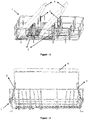
Figure 1 is a perspective view of an exemplary use of the holder and the washing rack comprising the holder according to the present invention. -
Figure 2 is a front view of an exemplary use of the holder and the washing rack comprising the holder according to the present invention. -
Figure 3 is another perspective view of an exemplary use of the holder and the washing rack comprising the holder according to the present invention. -
Figure 4 is a side view of an exemplary use of the holder and the washing rack comprising the holder according to the present invention. -
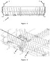
Figure 5 is another side view of another exemplary use of the holder and the washing rack comprising the holder according to the present invention. -
Figure 6 is a zoomed view of an exemplary use of the holder and the washing rack comprising the holder according to the present invention. -
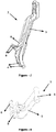
Figure 7 is a perspective view of the holder according to the present invention. -
Figure 8 is a perspective view of the joint comprised by the holder according to the present invention. - All the parts illustrated in figures are individually assigned a reference numeral and the corresponding terms of these numbers are listed below:
Washing rack (1) Base (1a) Frame (1b) Upper frame wire (1c) Lower frame wire (1d) Holder (2) First body (3) First tab (4) Pin (5) Second body (6) Joint (7) Second tab (8) Dishes (9) - In dishwashers there are generally provided a lot of washing racks positioned one above the other, wherein dishes as pots, plates, glasses, cups or the like are placed at these racks. The washing racks comprise various supporting protrusions for supporting the dishes that are placed thereon. However, while the protrusions support dishes as plates, glasses or the like, they are insufficient to support large dishes having relatively large surface area such as trays, pans etc. Therefore, large dishes placed at the washing racks, such as trays, pans or the like may be toppled or placed to occupy more space than necessary. Therefore, with the present invention, there is provided a holder and a washing rack comprising the holder, wherein the holder is suitable for being mounted to the washing rack, enables large dishes placed on the washing rack, such as trays or the like, to be supported, and is foldable and demountable from the washing rack.
- The holder (2) according to the present invention, exemplary views of which are illustrated in
Figures 1-8 , is suitable for use in a dishwasher which comprises at least one washing rack (1) on which dishes to be cleaned (9) are placed, wherein the washing rack (1) has at least one base (1a), and at least one frame (1b) forming a chamber structure by extending upwards from the base (1a) and comprising at least one upper frame wire (1c) and at least one lower frame wire (1d) located between the upper frame wire (1b) and the base (1a), the holder (2) comprising at least a first body (3) preferably in the form of a rod; at least a first tab (4) which is located at an end of the first body (3) and allows the first body (3) to be mounted to the lower frame wire (1d) such that the first body (3) is able to rotate around an axis formed by the lower frame wire (1d) and to move between a first position in which it is vertical with respect to the base (1a) and a second position in which it approaches the base (1a) so as to have an angle of less than 90° in between; at least one channel (not shown in the figures) provided at the first body (3); and at least one joint (7) which has at least a second body (6), at least one pin (5) located at an end of the second body (6) and positioned in the channel to move back and forth along the channel, and at least a second tab (8) located at the other end of the second body (6) and allowing the second body (6) to be mounted to the upper frame wire (1c) such that the second body (6) is able to move circularly around the axis formed by the upper frame wire (1c). - In an exemplary embodiment of the invention, the first body (3) and the joint (7) comprised by the holder (2) are engaged by placing the pin (5) at the channel, which is located at the first body (3), such that the pin (5) is able move back and forth in the channel. The first tab (4) is fastened to the lower frame wire (1d) and the second tab (8) is fastened to the upper frame wire (1c) to mount the holder (2) to the washing rack (1). By means of the first tab (8); the first body (3) which is mounted to the lower frame wire (1d) to be able to move circularly around an axis formed by the lower frame wire (1d) is therefore able to move between a first position in which it is vertical with respect to the base (1a) and approaches the frame (1b) and a second position in which it approaches the base (1a) so as to have an angle of less than 90° in between. By mounting the second tab (8) to the lower frame wire (1d), it is enabled that the joint (7) is mounted to the frame (1b) so as to move circularly around an axis formed by the lower frame wire (1d). In said embodiment, when the first body (3) is brought into the first position, the joint (7) moves circularly around an axis formed by the upper frame wire (1c), and at the same time, the pin (5) moves forward inside the channel towards a first point of the channel that is relatively away from the base (1a). When the first body (3) is in the first position, the holder (2) is located at closest position to the frame (1b) such that it does not occupy space inside the washing rack (1). If it is desired to place a dish (9) to the washing rack (1) which has a large surface area, such as a tray or the like, the first body (3) is moved to approach the base (1a). When the first body (3) approaches towards the base (1a), the pin (5) moves inside the channel towards a second point of the channel that is relatively closer to the base, and the second body (6) rotates around the axis formed by the upper frame wire (1c), taking a relatively horizontal position with respect to the base (1a). When the pin (5) reaches to the second point of the channel, the holder (2) is fixed in its position. When the holder (2) is in said position, the first body (3) forms a protrusion by which dishes (9) to be placed at the washing rack (1), such as tray or the like, are supported, and the dishes (9) lean against the first body (3) to be placed inside the washing rack (1).
- The washing rack (1) according to the present invention, on which dishes (9) to be cleaned are placed, comprises at least one base (1a); at least one frame (1b) forming a chamber structure by extending upwards from the base (1a) and comprising at least one upper frame wire (1c) and at least one lower frame wire (1d) located between the upper frame wire (1c) and the base (1a); and at least one holder which has at least a first body (3) preferably in the form of a rod; at least a first tab (4) which is located at an end of the first body (3) and allows the first body (3) to be mounted to the lower frame wire (1d) such that the first body (3) is able to rotate around an axis formed by the lower frame wire (1d) and to move between a first position in which it is vertical with respect to the base (1a) and a second position in which it approaches the base (1a) so as to have an angle of less than 90° in between; at least one channel provided at the first body (3); and at least one joint (7), wherein the joint (7) comprises:
- at least a second body (6);
- at least one pin (5) located at an end of the second body (6) and positioned in the channel to move back and forth along the channel; and
- at least a second tab (8) located at the other end of the second body (6) and allowing the second body (6) to be mounted to the upper frame wire (1c) such that the second body (6) is able to move circularly around the axis formed by the upper frame wire (1c).
- In a preferred embodiment of the invention, the washing rack (1) comprises at least two holders (2) which are positioned in an opposed manner so that the dishes (9) as trays or the like can be positioned by leaning against the first bodies (3) which extend in an opposed manner.
- In a preferred embodiment of the invention, length of the second body (6) (length between the second tab (8) and the pin (5)) is smaller than length of the first body (3) (length between the first tab (4) and the other end of the first body (3) that is located opposite the first tab (4)). Therefore, when the first body (3) is in the second position, the second body (6) can be positioned parallel to the base (1a).
- In a preferred embodiment of the invention, the holder (2) comprises at least one fixing member which is located at the channel and allows the pin (5) to be fixed at the first point and the second point of the channel. The fixing member is preferably a protrusion located at the first body (3) and acts as a lock for the joint (7) to keep the first body (3) fixed in the vertical position.
- In a preferred embodiment of the invention, the first body (3) comprises at least one extension in the form of a clamp which enables dishes (9) placed at the washing rack (1) to be fixed, and is provided at the other end of the first body (3) opposite the end where the first tab (4) is provided.
- Thanks to the holder (2) according to the present invention, it is enabled that dishes (9) having a relatively large surface area, such as trays, pans or the like, are placed inside the washing rack (1) such that they occupy less space and are not toppled. Since the holder (2) is movable, it can be fixed at a position at the washing rack (1) so as not to occupy space, when not in use. Thanks to the first tab (4) and the second tab (8) comprised by the holder (2), the holder (2) can be mounted to the washing rack (1) by the user so that it can be easily removed from the washing rack (1) if desired.
Claims (9)
- A holder (2) suitable for use in a dishwasher which comprises at least one washing rack (1) on which dishes to be cleaned (9) are placed, wherein the washing rack (1) has at least one base (1a), and at least one frame (1b) forming a chamber structure by extending upwards from the base (1a) and comprising at least one upper frame wire (1c) and at least one lower frame wire (1d) located between the upper frame wire (1b) and the base (1a), characterized by comprising at least a first body (3); at least a first tab (4) which is located at an end of the first body (3) and allows the first body (3) to be mounted to the lower frame wire (1d) such that the first body (3) is able to rotate around an axis formed by the lower frame wire (1d) and to move between a first position in which it is vertical with respect to the base (1a) and a second position in which it approaches the base (1a) so as to have an angle of less than 90° in between; at least one channel provided at the first body (3); and at least one joint (7) which has at least a second body (6), at least one pin (5) located at an end of the second body (6) and positioned in the channel to move back and forth along the channel, and at least a second tab (8) located at the other end of the second body (6) and allowing the second body (6) to be mounted to the upper frame wire (1c) such that the second body (6) is able to move circularly around the axis formed by the upper frame wire (1c).
- A holder (2) according to Claim 1, characterized in that length of the second body (6) is smaller than length of the first body (3).
- A holder (2) according to any of the Claims 1 or 2, characterized by comprising at least one fixing member which is located at the channel and allows the pin (5) to be fixed at the first point and the second point of the channel.
- A holder (2) according to any of the preceding claims, characterized in that the first body (3) comprises at least one extension in the form of a clamp which enables dishes (9) placed at the washing rack (1) to be fixed, and is provided at the other end of the first body (3) opposite the end where the first tab (4) is provided.
- A washing rack (1) on which dishes (9) to be cleaned are placed and which comprises at least one base (1a); at least one frame (1b) forming a chamber structure by extending upwards from the base (1a) and comprising at least one upper frame wire (1c) and at least one lower frame wire (1d) located between the upper frame wire (1c) and the base (1a); characterized by comprising at least one holder which has at least a first body (3); at least a first tab (4) which is located at an end of the first body (3) and allows the first body (3) to be mounted to the lower frame wire (1d) such that the first body (3) is able to rotate around an axis formed by the lower frame wire (1d) and to move between a first position in which it is vertical with respect to the base (1a) and a second position in which it approaches the base (1a) so as to have an angle of less than 90° in between; at least one channel provided at the first body (3); and at least one joint (7), wherein the joint (7) comprises:- at least a second body (6);- at least one pin (5) located at an end of the second body (6) and positioned in the channel to move back and forth along the channel; and- at least a second tab (8) located at the other end of the second body (6) and allowing the second body (6) to be mounted to the upper frame wire (1c) such that the second body (6) is able to move circularly around the axis formed by the upper frame wire (1c).
- A washing rack (1) according to Claim 5, characterized in that length of the second body (6) is smaller than length of the first body (3).
- A washing rack (1) according to any of the Claims 5 or 6, characterized by comprising at least one fixing member which is located at the channel and allows the pin (5) to be fixed at the first point and the second point of the channel.
- A washing rack (1) according to any of the Claims 5 to 7, characterized by comprising at least two holders (2) which are positioned in an opposed manner.
- A washing rack (1) according to any of the Claims 5 to 8, characterized in that the first body (3) comprises at least one extension in the form of a clamp which enables dishes (9) placed at the washing rack (1) to be fixed, and is provided at the other end of the first body (3) opposite the end where the first tab (4) is provided.
Applications Claiming Priority (1)
| Application Number | Priority Date | Filing Date | Title |
|---|---|---|---|
| TR201814440 | 2018-10-03 |
Publications (2)
| Publication Number | Publication Date |
|---|---|
| EP3632290A1 true EP3632290A1 (en) | 2020-04-08 |
| EP3632290B1 EP3632290B1 (en) | 2022-05-11 |
Family
ID=68210708
Family Applications (1)
| Application Number | Title | Priority Date | Filing Date |
|---|---|---|---|
| EP19201047.8A Active EP3632290B1 (en) | 2018-10-03 | 2019-10-02 | A washing rack comprising a holder |
Country Status (1)
| Country | Link |
|---|---|
| EP (1) | EP3632290B1 (en) |
Citations (7)
| Publication number | Priority date | Publication date | Assignee | Title |
|---|---|---|---|---|
| US5158185A (en) * | 1991-09-27 | 1992-10-27 | Maytag Corporation | Dividers for dishwasher racking system |
| US20050109378A1 (en) * | 2003-11-20 | 2005-05-26 | Landsiedel Jay C. | Dishwasher and adjustable rack |
| WO2012110319A2 (en) * | 2011-02-17 | 2012-08-23 | BSH Bosch und Siemens Hausgeräte GmbH | Appliance with a support rack having a plurality of support elements |
| ITTO20110740A1 (en) * | 2011-08-05 | 2013-02-06 | Indesit Co Spa | BASKET FOR DISHWASHER MACHINE INCLUDING A FOLDABLE SUPPORT, PREFERABLY FOR THE POSITIONING OF PENTOLAME. |
| EP2815690A1 (en) * | 2013-06-19 | 2014-12-24 | BSH Bosch und Siemens Hausgeräte GmbH | Glass holder for a dish basket of a dishwasher, dish basket for a dishwasher and dishwasher |
| EP3045099A2 (en) | 2011-08-05 | 2016-07-20 | Indesit Company S.p.A. | Dishwasher rack comprising folding/tilting supports |
| CN107440664A (en) * | 2016-05-30 | 2017-12-08 | 青岛海尔洗碗机有限公司 | A kind of dish-washing machine and the support frame for being used for supporter in the dish-washing machine |
-
2019
- 2019-10-02 EP EP19201047.8A patent/EP3632290B1/en active Active
Patent Citations (7)
| Publication number | Priority date | Publication date | Assignee | Title |
|---|---|---|---|---|
| US5158185A (en) * | 1991-09-27 | 1992-10-27 | Maytag Corporation | Dividers for dishwasher racking system |
| US20050109378A1 (en) * | 2003-11-20 | 2005-05-26 | Landsiedel Jay C. | Dishwasher and adjustable rack |
| WO2012110319A2 (en) * | 2011-02-17 | 2012-08-23 | BSH Bosch und Siemens Hausgeräte GmbH | Appliance with a support rack having a plurality of support elements |
| ITTO20110740A1 (en) * | 2011-08-05 | 2013-02-06 | Indesit Co Spa | BASKET FOR DISHWASHER MACHINE INCLUDING A FOLDABLE SUPPORT, PREFERABLY FOR THE POSITIONING OF PENTOLAME. |
| EP3045099A2 (en) | 2011-08-05 | 2016-07-20 | Indesit Company S.p.A. | Dishwasher rack comprising folding/tilting supports |
| EP2815690A1 (en) * | 2013-06-19 | 2014-12-24 | BSH Bosch und Siemens Hausgeräte GmbH | Glass holder for a dish basket of a dishwasher, dish basket for a dishwasher and dishwasher |
| CN107440664A (en) * | 2016-05-30 | 2017-12-08 | 青岛海尔洗碗机有限公司 | A kind of dish-washing machine and the support frame for being used for supporter in the dish-washing machine |
Also Published As
| Publication number | Publication date |
|---|---|
| EP3632290B1 (en) | 2022-05-11 |
Similar Documents
| Publication | Publication Date | Title |
|---|---|---|
| US3269548A (en) | Rack construction for dishwashing machine | |
| US5480035A (en) | Dishwasher rack with adjustable shelf | |
| US8714371B2 (en) | Dishwasher basket with a cup support | |
| US20190069756A1 (en) | Specialty dishwasher for glasses and lower rack for same | |
| WO2013045543A1 (en) | A rack suitable for usage in a dishwasher and the dishwasher wherein the rack is used | |
| US9629515B2 (en) | Multi-sided, rotable tines for a dishwasher rack | |
| CN113747821A (en) | Dish washing machine | |
| US20130057132A1 (en) | Basket Assembly For Dishwasher | |
| US7909181B2 (en) | Article holders | |
| US20140021149A1 (en) | Stemware holder | |
| EP3357399A1 (en) | Dish rack retaining clip | |
| KR101397037B1 (en) | Basket for a dishwasher and Dishwasher using the same | |
| CN114828724B (en) | Rinse container | |
| US20140117823A1 (en) | Dishwasher | |
| EP3632290A1 (en) | A holder mountable to a washing rack and a washing rack comprising a holder | |
| EP1286616B1 (en) | Dishwasher basket with foldable crockery holder racks | |
| US10426315B2 (en) | Dishwasher | |
| WO2013098292A1 (en) | A rack suitable for using in a dishwasher and the dishwasher wherein the rack is used | |
| WO2016192792A1 (en) | Foldable stemware holder and dishwasher having the same | |
| KR20090024004A (en) | dish washer | |
| CN113712484B (en) | Baking tray support component and dish washing machine | |
| CN118922117A (en) | Basket device | |
| EP3593697B1 (en) | Cutlery basket for dishwashers | |
| JP2007244404A (en) | Dishwasher rack equipment | |
| JP2018019943A (en) | Dishwasher |
Legal Events
| Date | Code | Title | Description |
|---|---|---|---|
| PUAI | Public reference made under article 153(3) epc to a published international application that has entered the european phase |
Free format text: ORIGINAL CODE: 0009012 |
|
| STAA | Information on the status of an ep patent application or granted ep patent |
Free format text: STATUS: THE APPLICATION HAS BEEN PUBLISHED |
|
| AK | Designated contracting states |
Kind code of ref document: A1 Designated state(s): AL AT BE BG CH CY CZ DE DK EE ES FI FR GB GR HR HU IE IS IT LI LT LU LV MC MK MT NL NO PL PT RO RS SE SI SK SM TR |
|
| AX | Request for extension of the european patent |
Extension state: BA ME |
|
| STAA | Information on the status of an ep patent application or granted ep patent |
Free format text: STATUS: REQUEST FOR EXAMINATION WAS MADE |
|
| 17P | Request for examination filed |
Effective date: 20201006 |
|
| RBV | Designated contracting states (corrected) |
Designated state(s): AL AT BE BG CH CY CZ DE DK EE ES FI FR GB GR HR HU IE IS IT LI LT LU LV MC MK MT NL NO PL PT RO RS SE SI SK SM TR |
|
| GRAP | Despatch of communication of intention to grant a patent |
Free format text: ORIGINAL CODE: EPIDOSNIGR1 |
|
| STAA | Information on the status of an ep patent application or granted ep patent |
Free format text: STATUS: GRANT OF PATENT IS INTENDED |
|
| INTG | Intention to grant announced |
Effective date: 20211203 |
|
| GRAS | Grant fee paid |
Free format text: ORIGINAL CODE: EPIDOSNIGR3 |
|
| GRAA | (expected) grant |
Free format text: ORIGINAL CODE: 0009210 |
|
| STAA | Information on the status of an ep patent application or granted ep patent |
Free format text: STATUS: THE PATENT HAS BEEN GRANTED |
|
| AK | Designated contracting states |
Kind code of ref document: B1 Designated state(s): AL AT BE BG CH CY CZ DE DK EE ES FI FR GB GR HR HU IE IS IT LI LT LU LV MC MK MT NL NO PL PT RO RS SE SI SK SM TR |
|
| REG | Reference to a national code |
Ref country code: GB Ref legal event code: FG4D |
|
| REG | Reference to a national code |
Ref country code: CH Ref legal event code: EP |
|
| REG | Reference to a national code |
Ref country code: AT Ref legal event code: REF Ref document number: 1490696 Country of ref document: AT Kind code of ref document: T Effective date: 20220515 |
|
| REG | Reference to a national code |
Ref country code: DE Ref legal event code: R096 Ref document number: 602019014794 Country of ref document: DE |
|
| REG | Reference to a national code |
Ref country code: IE Ref legal event code: FG4D |
|
| REG | Reference to a national code |
Ref country code: LT Ref legal event code: MG9D |
|
| REG | Reference to a national code |
Ref country code: NL Ref legal event code: MP Effective date: 20220511 |
|
| REG | Reference to a national code |
Ref country code: DE Ref legal event code: R084 Ref document number: 602019014794 Country of ref document: DE |
|
| REG | Reference to a national code |
Ref country code: AT Ref legal event code: MK05 Ref document number: 1490696 Country of ref document: AT Kind code of ref document: T Effective date: 20220511 |
|
| PG25 | Lapsed in a contracting state [announced via postgrant information from national office to epo] |
Ref country code: SE Free format text: LAPSE BECAUSE OF FAILURE TO SUBMIT A TRANSLATION OF THE DESCRIPTION OR TO PAY THE FEE WITHIN THE PRESCRIBED TIME-LIMIT Effective date: 20220511 Ref country code: PT Free format text: LAPSE BECAUSE OF FAILURE TO SUBMIT A TRANSLATION OF THE DESCRIPTION OR TO PAY THE FEE WITHIN THE PRESCRIBED TIME-LIMIT Effective date: 20220912 Ref country code: NO Free format text: LAPSE BECAUSE OF FAILURE TO SUBMIT A TRANSLATION OF THE DESCRIPTION OR TO PAY THE FEE WITHIN THE PRESCRIBED TIME-LIMIT Effective date: 20220811 Ref country code: NL Free format text: LAPSE BECAUSE OF FAILURE TO SUBMIT A TRANSLATION OF THE DESCRIPTION OR TO PAY THE FEE WITHIN THE PRESCRIBED TIME-LIMIT Effective date: 20220511 Ref country code: LT Free format text: LAPSE BECAUSE OF FAILURE TO SUBMIT A TRANSLATION OF THE DESCRIPTION OR TO PAY THE FEE WITHIN THE PRESCRIBED TIME-LIMIT Effective date: 20220511 Ref country code: HR Free format text: LAPSE BECAUSE OF FAILURE TO SUBMIT A TRANSLATION OF THE DESCRIPTION OR TO PAY THE FEE WITHIN THE PRESCRIBED TIME-LIMIT Effective date: 20220511 Ref country code: GR Free format text: LAPSE BECAUSE OF FAILURE TO SUBMIT A TRANSLATION OF THE DESCRIPTION OR TO PAY THE FEE WITHIN THE PRESCRIBED TIME-LIMIT Effective date: 20220812 Ref country code: FI Free format text: LAPSE BECAUSE OF FAILURE TO SUBMIT A TRANSLATION OF THE DESCRIPTION OR TO PAY THE FEE WITHIN THE PRESCRIBED TIME-LIMIT Effective date: 20220511 Ref country code: ES Free format text: LAPSE BECAUSE OF FAILURE TO SUBMIT A TRANSLATION OF THE DESCRIPTION OR TO PAY THE FEE WITHIN THE PRESCRIBED TIME-LIMIT Effective date: 20220511 Ref country code: BG Free format text: LAPSE BECAUSE OF FAILURE TO SUBMIT A TRANSLATION OF THE DESCRIPTION OR TO PAY THE FEE WITHIN THE PRESCRIBED TIME-LIMIT Effective date: 20220811 Ref country code: AT Free format text: LAPSE BECAUSE OF FAILURE TO SUBMIT A TRANSLATION OF THE DESCRIPTION OR TO PAY THE FEE WITHIN THE PRESCRIBED TIME-LIMIT Effective date: 20220511 |
|
| PG25 | Lapsed in a contracting state [announced via postgrant information from national office to epo] |
Ref country code: RS Free format text: LAPSE BECAUSE OF FAILURE TO SUBMIT A TRANSLATION OF THE DESCRIPTION OR TO PAY THE FEE WITHIN THE PRESCRIBED TIME-LIMIT Effective date: 20220511 Ref country code: PL Free format text: LAPSE BECAUSE OF FAILURE TO SUBMIT A TRANSLATION OF THE DESCRIPTION OR TO PAY THE FEE WITHIN THE PRESCRIBED TIME-LIMIT Effective date: 20220511 Ref country code: LV Free format text: LAPSE BECAUSE OF FAILURE TO SUBMIT A TRANSLATION OF THE DESCRIPTION OR TO PAY THE FEE WITHIN THE PRESCRIBED TIME-LIMIT Effective date: 20220511 Ref country code: IS Free format text: LAPSE BECAUSE OF FAILURE TO SUBMIT A TRANSLATION OF THE DESCRIPTION OR TO PAY THE FEE WITHIN THE PRESCRIBED TIME-LIMIT Effective date: 20220911 |
|
| PG25 | Lapsed in a contracting state [announced via postgrant information from national office to epo] |
Ref country code: SM Free format text: LAPSE BECAUSE OF FAILURE TO SUBMIT A TRANSLATION OF THE DESCRIPTION OR TO PAY THE FEE WITHIN THE PRESCRIBED TIME-LIMIT Effective date: 20220511 Ref country code: SK Free format text: LAPSE BECAUSE OF FAILURE TO SUBMIT A TRANSLATION OF THE DESCRIPTION OR TO PAY THE FEE WITHIN THE PRESCRIBED TIME-LIMIT Effective date: 20220511 Ref country code: RO Free format text: LAPSE BECAUSE OF FAILURE TO SUBMIT A TRANSLATION OF THE DESCRIPTION OR TO PAY THE FEE WITHIN THE PRESCRIBED TIME-LIMIT Effective date: 20220511 Ref country code: EE Free format text: LAPSE BECAUSE OF FAILURE TO SUBMIT A TRANSLATION OF THE DESCRIPTION OR TO PAY THE FEE WITHIN THE PRESCRIBED TIME-LIMIT Effective date: 20220511 Ref country code: DK Free format text: LAPSE BECAUSE OF FAILURE TO SUBMIT A TRANSLATION OF THE DESCRIPTION OR TO PAY THE FEE WITHIN THE PRESCRIBED TIME-LIMIT Effective date: 20220511 Ref country code: CZ Free format text: LAPSE BECAUSE OF FAILURE TO SUBMIT A TRANSLATION OF THE DESCRIPTION OR TO PAY THE FEE WITHIN THE PRESCRIBED TIME-LIMIT Effective date: 20220511 |
|
| REG | Reference to a national code |
Ref country code: DE Ref legal event code: R097 Ref document number: 602019014794 Country of ref document: DE |
|
| PLBE | No opposition filed within time limit |
Free format text: ORIGINAL CODE: 0009261 |
|
| STAA | Information on the status of an ep patent application or granted ep patent |
Free format text: STATUS: NO OPPOSITION FILED WITHIN TIME LIMIT |
|
| PG25 | Lapsed in a contracting state [announced via postgrant information from national office to epo] |
Ref country code: AL Free format text: LAPSE BECAUSE OF FAILURE TO SUBMIT A TRANSLATION OF THE DESCRIPTION OR TO PAY THE FEE WITHIN THE PRESCRIBED TIME-LIMIT Effective date: 20220511 |
|
| 26N | No opposition filed |
Effective date: 20230214 |
|
| PG25 | Lapsed in a contracting state [announced via postgrant information from national office to epo] |
Ref country code: SI Free format text: LAPSE BECAUSE OF FAILURE TO SUBMIT A TRANSLATION OF THE DESCRIPTION OR TO PAY THE FEE WITHIN THE PRESCRIBED TIME-LIMIT Effective date: 20220511 Ref country code: MC Free format text: LAPSE BECAUSE OF FAILURE TO SUBMIT A TRANSLATION OF THE DESCRIPTION OR TO PAY THE FEE WITHIN THE PRESCRIBED TIME-LIMIT Effective date: 20220511 |
|
| REG | Reference to a national code |
Ref country code: CH Ref legal event code: PL |
|
| REG | Reference to a national code |
Ref country code: BE Ref legal event code: MM Effective date: 20221031 |
|
| PG25 | Lapsed in a contracting state [announced via postgrant information from national office to epo] |
Ref country code: LU Free format text: LAPSE BECAUSE OF NON-PAYMENT OF DUE FEES Effective date: 20221002 |
|
| PG25 | Lapsed in a contracting state [announced via postgrant information from national office to epo] |
Ref country code: LI Free format text: LAPSE BECAUSE OF NON-PAYMENT OF DUE FEES Effective date: 20221031 Ref country code: CH Free format text: LAPSE BECAUSE OF NON-PAYMENT OF DUE FEES Effective date: 20221031 |
|
| PG25 | Lapsed in a contracting state [announced via postgrant information from national office to epo] |
Ref country code: BE Free format text: LAPSE BECAUSE OF NON-PAYMENT OF DUE FEES Effective date: 20221031 |
|
| PG25 | Lapsed in a contracting state [announced via postgrant information from national office to epo] |
Ref country code: IE Free format text: LAPSE BECAUSE OF NON-PAYMENT OF DUE FEES Effective date: 20221002 |
|
| PG25 | Lapsed in a contracting state [announced via postgrant information from national office to epo] |
Ref country code: IT Free format text: LAPSE BECAUSE OF FAILURE TO SUBMIT A TRANSLATION OF THE DESCRIPTION OR TO PAY THE FEE WITHIN THE PRESCRIBED TIME-LIMIT Effective date: 20220511 |
|
| PG25 | Lapsed in a contracting state [announced via postgrant information from national office to epo] |
Ref country code: HU Free format text: LAPSE BECAUSE OF FAILURE TO SUBMIT A TRANSLATION OF THE DESCRIPTION OR TO PAY THE FEE WITHIN THE PRESCRIBED TIME-LIMIT; INVALID AB INITIO Effective date: 20191002 |
|
| PG25 | Lapsed in a contracting state [announced via postgrant information from national office to epo] |
Ref country code: CY Free format text: LAPSE BECAUSE OF FAILURE TO SUBMIT A TRANSLATION OF THE DESCRIPTION OR TO PAY THE FEE WITHIN THE PRESCRIBED TIME-LIMIT Effective date: 20220511 |
|
| PG25 | Lapsed in a contracting state [announced via postgrant information from national office to epo] |
Ref country code: MK Free format text: LAPSE BECAUSE OF FAILURE TO SUBMIT A TRANSLATION OF THE DESCRIPTION OR TO PAY THE FEE WITHIN THE PRESCRIBED TIME-LIMIT Effective date: 20220511 |
|
| PG25 | Lapsed in a contracting state [announced via postgrant information from national office to epo] |
Ref country code: MT Free format text: LAPSE BECAUSE OF FAILURE TO SUBMIT A TRANSLATION OF THE DESCRIPTION OR TO PAY THE FEE WITHIN THE PRESCRIBED TIME-LIMIT Effective date: 20220511 |
|
| PG25 | Lapsed in a contracting state [announced via postgrant information from national office to epo] |
Ref country code: BG Free format text: LAPSE BECAUSE OF FAILURE TO SUBMIT A TRANSLATION OF THE DESCRIPTION OR TO PAY THE FEE WITHIN THE PRESCRIBED TIME-LIMIT Effective date: 20220511 |
|
| PG25 | Lapsed in a contracting state [announced via postgrant information from national office to epo] |
Ref country code: BG Free format text: LAPSE BECAUSE OF FAILURE TO SUBMIT A TRANSLATION OF THE DESCRIPTION OR TO PAY THE FEE WITHIN THE PRESCRIBED TIME-LIMIT Effective date: 20220511 |
|
| PGFP | Annual fee paid to national office [announced via postgrant information from national office to epo] |
Ref country code: DE Payment date: 20241021 Year of fee payment: 6 |
|
| PGFP | Annual fee paid to national office [announced via postgrant information from national office to epo] |
Ref country code: GB Payment date: 20241025 Year of fee payment: 6 |
|
| PGFP | Annual fee paid to national office [announced via postgrant information from national office to epo] |
Ref country code: FR Payment date: 20241030 Year of fee payment: 6 |
|
| PGFP | Annual fee paid to national office [announced via postgrant information from national office to epo] |
Ref country code: TR Payment date: 20251001 Year of fee payment: 7 |