EP3631905B1 - Contact pin - Google Patents
Contact pin Download PDFInfo
- Publication number
- EP3631905B1 EP3631905B1 EP18727239.8A EP18727239A EP3631905B1 EP 3631905 B1 EP3631905 B1 EP 3631905B1 EP 18727239 A EP18727239 A EP 18727239A EP 3631905 B1 EP3631905 B1 EP 3631905B1
- Authority
- EP
- European Patent Office
- Prior art keywords
- retaining elements
- pair
- contact pin
- base body
- distance
- Prior art date
- Legal status (The legal status is an assumption and is not a legal conclusion. Google has not performed a legal analysis and makes no representation as to the accuracy of the status listed.)
- Active
Links
Images


Classifications
-
- H—ELECTRICITY
- H01—ELECTRIC ELEMENTS
- H01R—ELECTRICALLY-CONDUCTIVE CONNECTIONS; STRUCTURAL ASSOCIATIONS OF A PLURALITY OF MUTUALLY-INSULATED ELECTRICAL CONNECTING ELEMENTS; COUPLING DEVICES; CURRENT COLLECTORS
- H01R13/00—Details of coupling devices of the kinds covered by groups H01R12/70 or H01R24/00 - H01R33/00
- H01R13/02—Contact members
- H01R13/04—Pins or blades for co-operation with sockets
-
- H—ELECTRICITY
- H01—ELECTRIC ELEMENTS
- H01R—ELECTRICALLY-CONDUCTIVE CONNECTIONS; STRUCTURAL ASSOCIATIONS OF A PLURALITY OF MUTUALLY-INSULATED ELECTRICAL CONNECTING ELEMENTS; COUPLING DEVICES; CURRENT COLLECTORS
- H01R13/00—Details of coupling devices of the kinds covered by groups H01R12/70 or H01R24/00 - H01R33/00
- H01R13/40—Securing contact members in or to a base or case; Insulating of contact members
- H01R13/405—Securing in non-demountable manner, e.g. moulding, riveting
- H01R13/41—Securing in non-demountable manner, e.g. moulding, riveting by frictional grip in grommet, panel or base
Definitions
- the present invention generally relates to a contact pin for a plug connector according to Claim 1.
- the plug connector normally has an insulated pin housing with a circumferential flange and a chamber, wherein a plurality of contact pins which are plugged into a pin strip are arranged inside the pin housing.
- the contact pins have a base body and retaining elements moulded thereon which, for example, take the form of pairs of lugs which project beyond the circumference of the contact pin and which have a rising contour opposite to the mounting direction of the contact pin.
- the precipitous rear side of the retaining element is interlocked with the surrounding material of the pin strip, whereby a retention force is mobilised. If the retention force is exceeded during the plug-in process, the base material of the pin housing which surrounds the retaining element is placed locally, ruptured or broken up.
- Arranging the retaining elements, which are successive in the longitudinal direction, offset by 90° in the circumferential direction of the base body of the contact pin is further known, such that when the retention force is exceeded, both retaining elements touch undamaged base material, the very high assembly forces proving to be disadvantageous.
- the problem of the present invention is thus to provide a contact pin for an electrical plug connector which overcomes the abovementioned disadvantages, enables the highest possible retention forces and furthermore does not require assembly forces which are excessively high during assembly. Furthermore, the contact pin should be able to be produced cost-effectively and efficiently.
- US 2005/074 999 A1 teaches a connector with a housing formed with press-in holes, and terminals to be pressed into the press-in holes.
- Each terminal includes a tab connectable with a mating terminal, a base extending from the tab, and two press-in portions arranged side-by-side along the longitudinal direction on the base.
- Each press-in portion has press-in pieces projecting from the base in opposite outward directions and pressed into the housing.
- An inventive contact pin for a plug connector comprises a base body with a longitudinal axis x and a surface O.
- a first end of the contact pin is adapted to be plugged into an opening of a pin strip of the plug connector, the contact pin having at least four retaining elements which are moulded on the base body.
- Two retaining elements are each arranged successively spaced apart along the longitudinal axis x.
- two further retaining elements are each arranged oppositely at the same point of the longitudinal axis x in the circumferential direction.
- the retaining elements arranged successively are arranged offset from one another in the circumferential direction at an angle W1. According to the invention, it is envisaged that the angle W1 is smaller than 90°.
- each retaining element in the case of an undesired, touches at least partially undamaged base material of the pin strip and thus all retaining elements provide an approximately equal contribution to the retention force.
- the retention force thus becomes approximately constant along a large part of the withdrawal path.
- the angle W1 is smaller than 60°, preferably smaller than 45°, particularly preferably smaller than 30°.
- the retaining elements are formed by accumulations of material which protrude from the base body and which can be produced by various means. It is conceivable that these accumulations of material are provided by local deforming of the contact pin or by applying additional material by means of welding, soldering or adhesion.
- the contact pin has at least eight retaining elements, four of the retaining elements each being arranged relative to the longitudinal axis x on the same cross-section Q, those four retaining elements which are at a shorter distance relative to the first end than the remaining four retaining elements forming a first group and the remaining retaining elements a second group.
- a first pair and a second pair of the four retaining elements of the first group preferably each have a first distance a from one another, the first distance a being the same size in the case of the first pair and the second pair. Furthermore, a third pair and a fourth pair of the four retaining elements of the second group each have a second distance a' from one another, the second distance a' being the same size in the case of the third pair and the fourth pair.
- the first distance a is greater than the second distance a', the first pair and the third pair as well as the second pair and the fourth pair being arranged such that, in the event that the positions of all the retaining elements are projected onto the y-z plane, the projections of the third pair are located centrally between the projections of the first pair, and the projections of the fourth pair are located centrally between the projections of the second pair.
- each retaining element touches new base material without pre-damaging or with only a limited amount of pre-damage by preceding retaining elements, whereby the desired uniformly high deployment of the retention force is achieved.
- This effect can advantageously be amplified by at least two retaining elements, which are not arranged on the same cross-section Q relative to the longitudinal axis x, protruding to varying degrees from the base body, preferably the one of the two retaining elements which is moulded on the base body further away from the first end than the other retaining element protruding further from the base body.
- the retaining elements are moulded on the base body by a forging method, stamping method or embossing method.
- the retaining elements are formed, with respect to their number and their dimensions, such that the retention force of the contact pin from the pin housing reaches a value greater than or equal to 25 N, preferably greater than or equal to 40 N, particularly preferably greater than or equal to 60 N.
- a further subject-matter of the invention forms a plug connector for producing a mechanical and electrical connection to a mating plug, the plug connector having a pin housing with a pin strip for receiving at least one contact pin according to the invention.
- Figure 1 shows a contact pin 100 already disclosed in the prior art for a plug connection.
- the contact pin 100 consists of a mechanically resistant and electrically conductive material.
- a first end 101 of the contact pin 100 is provided to be plugged into an opening of a pin strip of a pin housing of a male plug connector.
- the contact pin 100 has a plurality of retaining elements 122 moulded on a base body 110 so that a pin strip which is assembled in this way is mechanically resilient when producing a plug connection between a male plug connector and a female mating plug.
- these retaining elements 122 are in this case arranged successively in the direction of a longitudinal axis x of the contact pin 100, which is known from the prior art and is not according to the invention because this configuration has the known disadvantages with regard to the amount of a retention force which can be mobilised to a maximum extent.
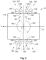
- Figure 2 schematically shows a cross-section Q and an inventive arrangement of the retaining elements 122 on the base body 110 of the contact pin 100.
- This cross-section Q which can have any shape in lieu of the depicted rectangular shape, for example round or square, is perpendicular to the longitudinal axis x shown in Figure 1 , which defines a first axis of a spatial, Cartesian coordinate system.
- the retaining elements 120 can be moulded on the base body 110 in a wedge-shaped or wing-shaped manner by a forging method, stamping method or embossing method such that they increasingly protrude from the base body 110 at an increasing distance from the first end (not depicted in detail).
- Figure 2 further shows a second axis y and a third axis z.
- the y-z plane which is spanned by these two axes is the plane in which the cross-section of the contact pin 100 can be specified at each point of the longitudinal axis x by corresponding y-z coordinates.
- An origin U of the coordinate system is specified in Figure 2 as the intersection of the two coordinate axes, the longitudinal axis x consequently runs perpendicular to the plane of projection, also through this point.
- the cross-section Q is delimited by a surface O of the base body 110.
- the contact pin 100 depicted in the figures has a first end which is adapted to be plugged into an opening of the pin strip of the plug connector.
- the contact pin 100 has at least four, in the depicted exemplary embodiment eight, retaining elements 120 moulded on the base body 110.
- Two retaining elements 120 are each arranged successively spaced apart along the longitudinal axis x, and two retaining elements 120 are each arranged oppositely at the same point of the longitudinal axis x in the circumferential direction.
- the retaining elements 120 arranged successively are arranged offset from one another in the circumferential direction at an angle W1 in such a way that the angle W1 is smaller than 30°.
- a position of each retaining element 120 on the base body 110 is given in the coordinate system in Figure 2 by a coordinate triple (xH, yH, zH) based on a centroid of volume 122 of each retaining element 120.
- the shape of the retaining elements 120 in the illustration is purely schematic and only serves to show the arrangement thereof along the surface of the base body 110.
- Two retaining elements 120 which are amalgamated in a first pair 123 and which have a distance a from one another, can be seen in the right part.
- a second pair 124 which is not identifiable as such in Figure 3 and which is arranged symmetrical with respect to the first pair relative to the longitudinal axis x, is located on the opposite side of the contact pin 100 which is not depicted. This can be easily understood taking into account the left part of Figure 3 and with reference to Figure 2 .
- a fourth pair 127 which is not identifiable as such in Figure 3 but which can also be easily understood taking into account the left part of Figure 3 and Figure 2 , is located on the opposite side of the contact pin 100 which is not depicted, in a symmetrical arrangement relative to the longitudinal axis x.
- the first distance a is greater than the second distance a', the first pair 123 and the third pair 126 as well as the second pair 124 and the fourth pair 127 being arranged such that, in the event that the positions of all the retaining elements 120 are projected onto the y-z plane, as shown in Figure 2 , the projections of the third pair 126 are located centrally between the projections of the first pair 123, and the projections of the fourth pair 127 are located centrally between the projections of the second pair 124.
- Figure 2 also shows that when the positions of all the retaining elements 120 are projected onto the y-z plane, the following applies: There are no two retaining elements 120 which have positions in the y-z plane which are located on a common connecting line with the origin U, provided that the origin is not located between the positions of the retaining elements 120 on the connecting line.
- At least two angular ranges W2 based on the origin as the vertex exist in the y-z plane, in which no retaining elements 120 are arranged, W2 respectively being greater than 120° in the depicted exemplary embodiment.
- the inventive arrangement of the retaining elements 120 on the base body ensures that each retaining element 120 touches at least partially undamaged base material of the pin strip, whereby all retaining elements provide an approximately equal contribution to the retention force.
Landscapes
- Manufacturing Of Electrical Connectors (AREA)
- Details Of Connecting Devices For Male And Female Coupling (AREA)
- Coupling Device And Connection With Printed Circuit (AREA)
- Connector Housings Or Holding Contact Members (AREA)
Description
- The present invention generally relates to a contact pin for a plug connector according to Claim 1.
- The plug connector normally has an insulated pin housing with a circumferential flange and a chamber, wherein a plurality of contact pins which are plugged into a pin strip are arranged inside the pin housing. In order to guarantee a secure fit of the contact pins in the pin housing, the contact pins have a base body and retaining elements moulded thereon which, for example, take the form of pairs of lugs which project beyond the circumference of the contact pin and which have a rising contour opposite to the mounting direction of the contact pin. Upon insertion/ assembly of the contact pin into the pin strip, said contact pin is successively expanded by the wedge shape of the retaining element, which facilitates the production of the plug connection and delimits the assembly forces. In the event of a straining of the contact pin, for example when producing a plug connection between a male plug connector and a female mating plug connector, the precipitous rear side of the retaining element is interlocked with the surrounding material of the pin strip, whereby a retention force is mobilised. If the retention force is exceeded during the plug-in process, the base material of the pin housing which surrounds the retaining element is placed locally, ruptured or broken up.
- In order to increase the maximum retention force, arranging at least two retaining elements in the direction of the longitudinal axis of the contact pin successively is known. It is disadvantageous that the retaining element, which is successive in the longitudinal direction, touches the already pre-damaged base material, whereby this successive retaining element can only provide a reduced contribution to the retention force.
- Arranging the retaining elements, which are successive in the longitudinal direction, offset by 90° in the circumferential direction of the base body of the contact pin is further known, such that when the retention force is exceeded, both retaining elements touch undamaged base material, the very high assembly forces proving to be disadvantageous.
- The problem of the present invention is thus to provide a contact pin for an electrical plug connector which overcomes the abovementioned disadvantages, enables the highest possible retention forces and furthermore does not require assembly forces which are excessively high during assembly. Furthermore, the contact pin should be able to be produced cost-effectively and efficiently.
-
US 2005/074 999 A1 teaches a connector with a housing formed with press-in holes, and terminals to be pressed into the press-in holes. Each terminal includes a tab connectable with a mating terminal, a base extending from the tab, and two press-in portions arranged side-by-side along the longitudinal direction on the base. Each press-in portion has press-in pieces projecting from the base in opposite outward directions and pressed into the housing. - These problems are solved by a contact pin with the features of Claim 1 and by a plug connector with the features of Claim 10. Preferred developments are specified in the dependent claims.
- An inventive contact pin for a plug connector comprises a base body with a longitudinal axis x and a surface O. A first end of the contact pin is adapted to be plugged into an opening of a pin strip of the plug connector, the contact pin having at least four retaining elements which are moulded on the base body. Two retaining elements are each arranged successively spaced apart along the longitudinal axis x. Moreover, two further retaining elements are each arranged oppositely at the same point of the longitudinal axis x in the circumferential direction. In this case, the retaining elements arranged successively are arranged offset from one another in the circumferential direction at an angle W1. According to the invention, it is envisaged that the angle W1 is smaller than 90°.
- Such an arrangement of the retaining elements on the base body ensures that each retaining element, in the case of an undesired, touches at least partially undamaged base material of the pin strip and thus all retaining elements provide an approximately equal contribution to the retention force. The retention force thus becomes approximately constant along a large part of the withdrawal path.
- At the same time, by means of the arrangement of the angle W1 and by means of its relatively small extension along the circumference of the contact pin, a delimitation of the assembly force which is to be applied for the assembly of the pin strip and a good guidance of the contact pin during the plug-in process are ensured. In this case, it is advantageous that the angle W1 is smaller than 60°, preferably smaller than 45°, particularly preferably smaller than 30°.
- In principle, it is possible according to the invention that the retaining elements are formed by accumulations of material which protrude from the base body and which can be produced by various means. It is conceivable that these accumulations of material are provided by local deforming of the contact pin or by applying additional material by means of welding, soldering or adhesion.
- In a particularly preferable configuration, the contact pin has at least eight retaining elements, four of the retaining elements each being arranged relative to the longitudinal axis x on the same cross-section Q, those four retaining elements which are at a shorter distance relative to the first end than the remaining four retaining elements forming a first group and the remaining retaining elements a second group.
- A first pair and a second pair of the four retaining elements of the first group preferably each have a first distance a from one another, the first distance a being the same size in the case of the first pair and the second pair. Furthermore, a third pair and a fourth pair of the four retaining elements of the second group each have a second distance a' from one another, the second distance a' being the same size in the case of the third pair and the fourth pair.
- In a preferred configuration, the first distance a is greater than the second distance a', the first pair and the third pair as well as the second pair and the fourth pair being arranged such that, in the event that the positions of all the retaining elements are projected onto the y-z plane, the projections of the third pair are located centrally between the projections of the first pair, and the projections of the fourth pair are located centrally between the projections of the second pair. In this manner, it is possible that, upon insertion of the contact pin into the opening of the pin strip, this is successively expanded in adjacent regions, which leads to the required assembly force being delimited. At the same time, each retaining element touches new base material without pre-damaging or with only a limited amount of pre-damage by preceding retaining elements, whereby the desired uniformly high deployment of the retention force is achieved.
- This effect can advantageously be amplified by at least two retaining elements, which are not arranged on the same cross-section Q relative to the longitudinal axis x, protruding to varying degrees from the base body, preferably the one of the two retaining elements which is moulded on the base body further away from the first end than the other retaining element protruding further from the base body.
- In a preferred embodiment, the retaining elements are moulded on the base body by a forging method, stamping method or embossing method.
- Advantageously, the retaining elements are moulded on the base body in a wedge-shaped or wing-shaped manner such that they increasingly protrude from the base body at an increasing distance from the first end.
- According to the invention, the retaining elements are formed, with respect to their number and their dimensions, such that the retention force of the contact pin from the pin housing reaches a value greater than or equal to 25 N, preferably greater than or equal to 40 N, particularly preferably greater than or equal to 60 N.
- A further subject-matter of the invention forms a plug connector for producing a mechanical and electrical connection to a mating plug, the plug connector having a pin housing with a pin strip for receiving at least one contact pin according to the invention.
- Further features, possible applications and advantages of the invention can be gathered from the following description of the exemplary embodiments of the invention, which are depicted in the figures. It should be noted here that the features depicted are merely descriptive in character and can also be used in combination with features of other further developments described above, and they are not intended to limit the invention in any way.
- The invention is explained in more detail hereafter with reference to the appended figures, wherein the same reference numbers are used for the same features. In the drawings:
- Figure 1
- shows a view of a contact pin from the prior art;
- Figure 2
- shows a schematic depiction of a cross-section of a contact pin according to the invention with projections of the retaining elements;
- Figure 3
- shows schematic depiction of a contact pin according to the invention in two views rotated by 90° relative to one another; and
- Figure 4
- shows the schematic depiction of a contact pin according to the invention in two views rotated by 90° relative to one another according to
Figure 3 , operating areas of the retaining elements being further indicated inFigure 4 . -
Figure 1 shows acontact pin 100 already disclosed in the prior art for a plug connection. Thecontact pin 100 consists of a mechanically resistant and electrically conductive material. Afirst end 101 of thecontact pin 100 is provided to be plugged into an opening of a pin strip of a pin housing of a male plug connector. - The
contact pin 100 has a plurality ofretaining elements 122 moulded on abase body 110 so that a pin strip which is assembled in this way is mechanically resilient when producing a plug connection between a male plug connector and a female mating plug. As can be inferred fromFigure 1 , theseretaining elements 122 are in this case arranged successively in the direction of a longitudinal axis x of thecontact pin 100, which is known from the prior art and is not according to the invention because this configuration has the known disadvantages with regard to the amount of a retention force which can be mobilised to a maximum extent. -
Figure 2 schematically shows a cross-section Q and an inventive arrangement of theretaining elements 122 on thebase body 110 of thecontact pin 100. This cross-section Q, which can have any shape in lieu of the depicted rectangular shape, for example round or square, is perpendicular to the longitudinal axis x shown inFigure 1 , which defines a first axis of a spatial, Cartesian coordinate system. In principle, theretaining elements 120 can be moulded on thebase body 110 in a wedge-shaped or wing-shaped manner by a forging method, stamping method or embossing method such that they increasingly protrude from thebase body 110 at an increasing distance from the first end (not depicted in detail). -
Figure 2 further shows a second axis y and a third axis z. The y-z plane which is spanned by these two axes is the plane in which the cross-section of thecontact pin 100 can be specified at each point of the longitudinal axis x by corresponding y-z coordinates. An origin U of the coordinate system is specified inFigure 2 as the intersection of the two coordinate axes, the longitudinal axis x consequently runs perpendicular to the plane of projection, also through this point. The cross-section Q is delimited by a surface O of thebase body 110. - The
contact pin 100 depicted in the figures has a first end which is adapted to be plugged into an opening of the pin strip of the plug connector. In principle, it is envisaged that thecontact pin 100 has at least four, in the depicted exemplary embodiment eight, retainingelements 120 moulded on thebase body 110. Tworetaining elements 120 are each arranged successively spaced apart along the longitudinal axis x, and tworetaining elements 120 are each arranged oppositely at the same point of the longitudinal axis x in the circumferential direction. The retainingelements 120 arranged successively are arranged offset from one another in the circumferential direction at an angle W1 in such a way that the angle W1 is smaller than 30°. - It is an advantage if the angle W1 between the successively arranged retaining
elements 120 is so small that a delimitation of the assembly force which is to be applied for the assembly of the pin strip with acontact pin 100 is ensured. - In principle, such an arrangement and configuration of the retaining
elements 120 guarantees the prevention of thecontact pin 100 being pushed out of the pin strip in the assembled state. This can be seen inFigure 3 , for example, and is later discussed in detail. - A position of each retaining
element 120 on thebase body 110 is given in the coordinate system inFigure 2 by a coordinate triple (xH, yH, zH) based on a centroid ofvolume 122 of each retainingelement 120. The shape of the retainingelements 120 in the illustration is purely schematic and only serves to show the arrangement thereof along the surface of thebase body 110. - When viewing
Figure 2 , the positions of all the retainingelements 120 are projected onto the y-z plane as a common plane, in order to be able to describe their arrangement in a clear manner. The arrangement of the retainingelements 120 on the surface O is described hereinafter. - Four retaining
elements 120 each have positions which differ in terms of value xH and are arranged on the same cross-section Q relative to the longitudinal axis x; this can be understood, for example, with reference toFigure 3 , which in the left part shows a lateral view and in the right part a plan view of theinventive contact pin 100 rotated by 90° relative thereto. - Two retaining
elements 120, which are amalgamated in afirst pair 123 and which have a distance a from one another, can be seen in the right part. Asecond pair 124, which is not identifiable as such inFigure 3 and which is arranged symmetrical with respect to the first pair relative to the longitudinal axis x, is located on the opposite side of thecontact pin 100 which is not depicted. This can be easily understood taking into account the left part ofFigure 3 and with reference toFigure 2 . - Furthermore, two retaining
elements 120 which are amalgamated in athird pair 126 and which are at a distance a' from one another can be seen in the right part ofFigure 3 . Afourth pair 127, which is not identifiable as such inFigure 3 but which can also be easily understood taking into account the left part ofFigure 3 andFigure 2 , is located on the opposite side of thecontact pin 100 which is not depicted, in a symmetrical arrangement relative to the longitudinal axis x. - As is inferred from
Figure 3 and alsoFigure 2 , the first distance a is greater than the second distance a', thefirst pair 123 and thethird pair 126 as well as thesecond pair 124 and thefourth pair 127 being arranged such that, in the event that the positions of all the retainingelements 120 are projected onto the y-z plane, as shown inFigure 2 , the projections of thethird pair 126 are located centrally between the projections of thefirst pair 123, and the projections of thefourth pair 127 are located centrally between the projections of thesecond pair 124. -
Figure 2 also shows that when the positions of all the retainingelements 120 are projected onto the y-z plane, the following applies:
There are no two retainingelements 120 which have positions in the y-z plane which are located on a common connecting line with the origin U, provided that the origin is not located between the positions of the retainingelements 120 on the connecting line. - Furthermore, at least two angular ranges W2 based on the origin as the vertex exist in the y-z plane, in which no retaining
elements 120 are arranged, W2 respectively being greater than 120° in the depicted exemplary embodiment. - By means of the arrangement of the angular ranges W2, in which no retaining
elements 120 or their projections are located, and by means of the relatively large extension of these angular ranges along the surface of thecontact pin 100, a delimitation of the assembly force to be applied for assembling the pin strip with acontact pin 100 is ensured. - Furthermore, as indicated in the right part in
Figure 4 , the inventive arrangement of the retainingelements 120 on the base body ensures that each retainingelement 120 touches at least partially undamaged base material of the pin strip, whereby all retaining elements provide an approximately equal contribution to the retention force. - In
Figure 4 , in this context, the lines of action, along which retainingelements 120 that are each arranged successively provide their contribution to the total retention force, are depicted as a region B1 and a region B2. The retention force thus becomes approximately constant along a large part of the withdrawal path. - Although the invention was explained in greater detail by the preferred exemplary embodiments, other combinations of the features mentioned can be provided by the person skilled in the art without departing from the scope of protection of the invention. The description of the figures is only for understanding the invention.
Claims (9)
- A contact pin (100) for a plug connector, comprising a base body (110) with a longitudinal axis (x) and a surface (O),wherein a first end of the contact pin (100) is adapted to be plugged into an opening of a pin strip of a plug housing of the plug connector,wherein the contact pin (100) has at least four retaining elements (120) moulded on the base body (110), wherein two retaining elements (120) are each arranged successively spaced apart along the longitudinal axis (x), wherein two retaining elements (120) are further each arranged oppositely at the same point of the longitudinal axis (x) in the circumferential direction, andwherein the retaining elements (120) arranged successively are arranged in the circumferential direction at an angle (W1) offset from one another,characterised in thatthe angle (W1) is smaller than 30°,wherein the retaining elements (120) are formed, with respect to their number and their dimensions, such that a retention force of the contact pin (100) from the pin housing reaches a value greater than or equal to 25 N.
- The contact pin (100) according to Claim 1, characterised in that the retaining elements (120) are formed by accumulations of material which protrude from the base body (110).
- The contact pin (100) according to any one of the preceding claims, characterised in that the contact pin (100) has at least eight retaining elements (120), wherein four of the retaining elements (120) are each arranged relative to the longitudinal axis (x) on the same cross-section (Q), wherein those four retaining elements (120) which are at a shorter distance relative to the first end than the remaining four retaining elements (120) form a first group (125) and the remaining retaining elements (120) a second group (128).
- The contact pin (100) according to Claim 3, characterised in that a first pair (123) and a second pair (124) of the four retaining elements (120) of the first group (125) each have a first distance (a) from one another, wherein the first distance (a) is the same size in the case of the first pair (123) and the second pair (124), and that a third pair (126) and a fourth pair (127) of the four retaining elements (120) of the second group (128) each have a second distance (a') from one another, wherein the second distance (a') is the same size in the case of the third pair (126) and the fourth pair (127).
- The contact pin (100) according to Claim 4, characterised in that the first distance (a) is greater than the second distance (a'), wherein the first pair (123) and the third pair (126) as well as the second pair (124) and the fourth pair (127) are arranged such that, in the event that the positions of all the retaining elements (120) are projected onto a gravity axis of a cross-section of the contact pin, the projections of the third pair (126) are located centrally between the projections of the first pair (123), and the projections of the fourth pair (127) are located centrally between the projections of the second pair (124).
- The contact pin (100) according to any one of the preceding claims, characterised in that at least two retaining elements (120', 120"), which are not located at the same point of the longitudinal axis (x), protrude to varying degrees from the base body (110), wherein preferably the one of the two retaining elements (120') which is moulded on the base body (110) further away from the first end than the other retaining element (120") protrudes further from the base body (110).
- The contact pin (100) according to any one of the preceding claims, characterised in that the retaining elements (120) are moulded on the base body (110) by a forging method, stamping method or embossing method.
- The contact pin (100) according to any one of the preceding claims, characterised in that the retaining elements (120) are moulded on the base body (110) in a wedge-shaped or wing-shaped manner such that they increasingly protrude from the base body (110) at an increasing distance from the first end.
- A plug connector for producing a mechanical and electrical connection to a mating plug, wherein the plug connector has a pin housing with a pin strip comprising at least one contact pin (100) according to any one of the preceding claims.
Applications Claiming Priority (2)
| Application Number | Priority Date | Filing Date | Title |
|---|---|---|---|
| DE102017111293.6A DE102017111293A1 (en) | 2017-05-23 | 2017-05-23 | pin |
| PCT/EP2018/063251 WO2018215385A1 (en) | 2017-05-23 | 2018-05-21 | Contact pin |
Publications (2)
| Publication Number | Publication Date |
|---|---|
| EP3631905A1 EP3631905A1 (en) | 2020-04-08 |
| EP3631905B1 true EP3631905B1 (en) | 2025-06-25 |
Family
ID=62245280
Family Applications (1)
| Application Number | Title | Priority Date | Filing Date |
|---|---|---|---|
| EP18727239.8A Active EP3631905B1 (en) | 2017-05-23 | 2018-05-21 | Contact pin |
Country Status (6)
| Country | Link |
|---|---|
| US (1) | US11069996B2 (en) |
| EP (1) | EP3631905B1 (en) |
| JP (1) | JP2020521304A (en) |
| CN (1) | CN110651397B (en) |
| DE (1) | DE102017111293A1 (en) |
| WO (1) | WO2018215385A1 (en) |
Families Citing this family (2)
| Publication number | Priority date | Publication date | Assignee | Title |
|---|---|---|---|---|
| CN213520383U (en) * | 2020-07-20 | 2021-06-22 | 泰科电子(上海)有限公司 | Conductive terminal |
| DE102021003933A1 (en) * | 2020-09-24 | 2022-03-24 | Ingun Prüfmittelbau Gmbh | contact unit and contact pin |
Citations (1)
| Publication number | Priority date | Publication date | Assignee | Title |
|---|---|---|---|---|
| DE1540251A1 (en) * | 1964-01-06 | 1969-11-27 | Oxley Robert Frederick | Connection pin for printed circuits |
Family Cites Families (32)
| Publication number | Priority date | Publication date | Assignee | Title |
|---|---|---|---|---|
| US3998518A (en) * | 1972-04-04 | 1976-12-21 | Bunker Ramo Corporation | Electrical connector having improved releasable contact construction |
| US4057315A (en) * | 1976-08-02 | 1977-11-08 | E. I. Du Pont De Nemours And Company | Circuit board pin |
| US5035656A (en) * | 1990-05-15 | 1991-07-30 | E. I. Du Pont De Nemours And Company | Connector, circuit board contact element and retention portion |
| US5064389A (en) * | 1991-06-19 | 1991-11-12 | Amp Incorporated | Electrical slave connector |
| US5147227A (en) | 1991-10-17 | 1992-09-15 | Amp Incorporated | Terminal retention device |
| US5252088A (en) * | 1992-10-05 | 1993-10-12 | General Motors Corporation | Sealed pass through electrical connector |
| DE9314676U1 (en) * | 1993-09-28 | 1994-02-24 | Siemens AG, 80333 München | Contact pin for plug connections |
| US5460549A (en) * | 1994-09-02 | 1995-10-24 | Itt Industries, Inc. | Connector with sealed contacts |
| US5885113A (en) * | 1995-05-11 | 1999-03-23 | Itt Manufacturing Enterprises, Inc. | Connector with retained contacts |
| DE29700452U1 (en) * | 1997-01-13 | 1997-02-27 | Framatome Connectors Daut + Rietz GmbH, 90411 Nürnberg | Contact pin with opposite anchoring wings and connector element |
| US5897401A (en) * | 1997-07-01 | 1999-04-27 | Solid State Stamping, Inc. | Serrated starred pin |
| US6042429A (en) * | 1997-08-18 | 2000-03-28 | Autosplice Systems Inc. | Continuous press-fit knurl pin |
| US5980271A (en) * | 1998-04-15 | 1999-11-09 | Hon Hai Precision Ind. Co., Ltd. | Header connector of a future bus and related compliant pins |
| JP3503877B2 (en) * | 1999-02-19 | 2004-03-08 | 矢崎総業株式会社 | Terminal structure for board using square wire |
| DE10257759A1 (en) * | 2002-12-10 | 2004-06-24 | Erni Elektroapparate Gmbh | Electrical connector with a housing and a high current contact |
| US6896559B2 (en) * | 2003-03-14 | 2005-05-24 | Tyco Electronics Corporation | Pin retention apparatus, methods and articles of manufacture |
| JP4069817B2 (en) * | 2003-07-10 | 2008-04-02 | 住友電装株式会社 | connector |
| JP4707970B2 (en) * | 2004-05-28 | 2011-06-22 | 矢崎総業株式会社 | Connector terminals and connectors |
| DE102004032572B4 (en) * | 2004-07-05 | 2010-03-04 | Tyco Electronics Amp Gmbh | Connecting arrangement with contact pin |
| JP2009043676A (en) * | 2007-08-10 | 2009-02-26 | Tyco Electronics Amp Kk | Press-fitting terminal, terminal press-fitting structure, and electrical connector |
| JP5115149B2 (en) * | 2007-11-02 | 2013-01-09 | 住友電装株式会社 | connector |
| EP2255411B1 (en) * | 2008-02-21 | 2015-07-01 | Melni LLC | Electrical connector |
| JP5053338B2 (en) * | 2009-07-23 | 2012-10-17 | 京セラコネクタプロダクツ株式会社 | Contacts and connectors |
| JP5299708B2 (en) * | 2010-02-15 | 2013-09-25 | 住友電装株式会社 | PCB terminal |
| DE102010064071B3 (en) * | 2010-12-23 | 2012-05-24 | Tyco Electronics Amp Gmbh | Clamping ring, cable gland and method for mounting a cable gland |
| TWM427707U (en) * | 2011-06-21 | 2012-04-21 | Ks Terminals Inc | Electrical connector terminal and electrical connector terminal with waterproof connector |
| EP2579396B1 (en) * | 2011-10-04 | 2016-12-21 | Tyco Electronics Nederland B.V. | Shielded enclosure assembly for at least one in particular standardized connector on a cable |
| JP2015082340A (en) * | 2013-10-21 | 2015-04-27 | 矢崎総業株式会社 | Charge connector |
| US9537278B2 (en) * | 2015-02-09 | 2017-01-03 | Yazaki Corporation | Terminal group and connector |
| JP6550890B2 (en) * | 2015-04-22 | 2019-07-31 | 住友電装株式会社 | Press-fit terminal |
| US9595782B2 (en) * | 2015-08-05 | 2017-03-14 | Te Connectivity Corporation | Pin with angled retention member |
| JP7005507B2 (en) * | 2016-02-26 | 2022-01-21 | ローゼンベルガー ホーフフレクベンツテクニーク ゲーエムベーハー ウント ツェーオー カーゲー | Electrical plug connector |
-
2017
- 2017-05-23 DE DE102017111293.6A patent/DE102017111293A1/en active Pending
-
2018
- 2018-05-21 JP JP2020514347A patent/JP2020521304A/en active Pending
- 2018-05-21 CN CN201880033652.1A patent/CN110651397B/en active Active
- 2018-05-21 EP EP18727239.8A patent/EP3631905B1/en active Active
- 2018-05-21 WO PCT/EP2018/063251 patent/WO2018215385A1/en not_active Ceased
-
2019
- 2019-11-15 US US16/685,482 patent/US11069996B2/en active Active
Patent Citations (1)
| Publication number | Priority date | Publication date | Assignee | Title |
|---|---|---|---|---|
| DE1540251A1 (en) * | 1964-01-06 | 1969-11-27 | Oxley Robert Frederick | Connection pin for printed circuits |
Also Published As
| Publication number | Publication date |
|---|---|
| DE102017111293A1 (en) | 2018-11-29 |
| EP3631905A1 (en) | 2020-04-08 |
| US11069996B2 (en) | 2021-07-20 |
| US20200083628A1 (en) | 2020-03-12 |
| WO2018215385A1 (en) | 2018-11-29 |
| CN110651397A (en) | 2020-01-03 |
| CN110651397B (en) | 2021-08-10 |
| JP2020521304A (en) | 2020-07-16 |
Similar Documents
| Publication | Publication Date | Title |
|---|---|---|
| US3550067A (en) | Electrical receptacle and terminal | |
| EP3134943B1 (en) | Terminal fitting | |
| RU2623730C2 (en) | Socket contact | |
| JP6084133B2 (en) | connector | |
| EP0854542B1 (en) | Contact pin having anchoring wings in opposite directions, and connector element | |
| CN102106043A (en) | Socket contact | |
| US20090311898A1 (en) | Hermaphroditic electrical contact | |
| EP1950841B1 (en) | A connector and assembling method therefor | |
| EP3550671A1 (en) | Relay terminal and relay connector | |
| US11069996B2 (en) | Contact pin for plug connector having retaining elements | |
| JP6301717B2 (en) | Contact connection structure | |
| EP2706618B1 (en) | Connector | |
| JP3812937B2 (en) | connector | |
| CN110391551A (en) | Electric connector | |
| KR20220098219A (en) | Plug with guide plate | |
| JP2016219097A (en) | Contact point connection structure | |
| EP3783744B1 (en) | Electric connection arrangement | |
| JP2015210948A (en) | Contact connection structure | |
| EP2575215B1 (en) | Terminal fitting | |
| JP6258660B2 (en) | Female terminal and connection structure | |
| JP6796619B2 (en) | Connection structure of electric wire and terminal | |
| JP6301723B2 (en) | Contact connection structure | |
| CN209150406U (en) | Electric connector | |
| JP6401490B2 (en) | Contact connection structure | |
| JP2015210863A (en) | Contact connection structure |
Legal Events
| Date | Code | Title | Description |
|---|---|---|---|
| STAA | Information on the status of an ep patent application or granted ep patent |
Free format text: STATUS: UNKNOWN |
|
| STAA | Information on the status of an ep patent application or granted ep patent |
Free format text: STATUS: THE INTERNATIONAL PUBLICATION HAS BEEN MADE |
|
| PUAI | Public reference made under article 153(3) epc to a published international application that has entered the european phase |
Free format text: ORIGINAL CODE: 0009012 |
|
| STAA | Information on the status of an ep patent application or granted ep patent |
Free format text: STATUS: REQUEST FOR EXAMINATION WAS MADE |
|
| 17P | Request for examination filed |
Effective date: 20191217 |
|
| AK | Designated contracting states |
Kind code of ref document: A1 Designated state(s): AL AT BE BG CH CY CZ DE DK EE ES FI FR GB GR HR HU IE IS IT LI LT LU LV MC MK MT NL NO PL PT RO RS SE SI SK SM TR |
|
| AX | Request for extension of the european patent |
Extension state: BA ME |
|
| DAV | Request for validation of the european patent (deleted) | ||
| DAX | Request for extension of the european patent (deleted) | ||
| STAA | Information on the status of an ep patent application or granted ep patent |
Free format text: STATUS: EXAMINATION IS IN PROGRESS |
|
| 17Q | First examination report despatched |
Effective date: 20210722 |
|
| GRAP | Despatch of communication of intention to grant a patent |
Free format text: ORIGINAL CODE: EPIDOSNIGR1 |
|
| STAA | Information on the status of an ep patent application or granted ep patent |
Free format text: STATUS: GRANT OF PATENT IS INTENDED |
|
| INTG | Intention to grant announced |
Effective date: 20250116 |
|
| GRAS | Grant fee paid |
Free format text: ORIGINAL CODE: EPIDOSNIGR3 |
|
| GRAA | (expected) grant |
Free format text: ORIGINAL CODE: 0009210 |
|
| STAA | Information on the status of an ep patent application or granted ep patent |
Free format text: STATUS: THE PATENT HAS BEEN GRANTED |
|
| AK | Designated contracting states |
Kind code of ref document: B1 Designated state(s): AL AT BE BG CH CY CZ DE DK EE ES FI FR GB GR HR HU IE IS IT LI LT LU LV MC MK MT NL NO PL PT RO RS SE SI SK SM TR |
|
| REG | Reference to a national code |
Ref country code: GB Ref legal event code: FG4D |
|
| REG | Reference to a national code |
Ref country code: CH Ref legal event code: EP |
|
| REG | Reference to a national code |
Ref country code: CH Ref legal event code: EP |
|
| REG | Reference to a national code |
Ref country code: IE Ref legal event code: FG4D |
|
| REG | Reference to a national code |
Ref country code: DE Ref legal event code: R096 Ref document number: 602018082893 Country of ref document: DE |
|
| PG25 | Lapsed in a contracting state [announced via postgrant information from national office to epo] |
Ref country code: FI Free format text: LAPSE BECAUSE OF FAILURE TO SUBMIT A TRANSLATION OF THE DESCRIPTION OR TO PAY THE FEE WITHIN THE PRESCRIBED TIME-LIMIT Effective date: 20250625 |
|
| REG | Reference to a national code |
Ref country code: LT Ref legal event code: MG9D |
|
| PG25 | Lapsed in a contracting state [announced via postgrant information from national office to epo] |
Ref country code: NO Free format text: LAPSE BECAUSE OF FAILURE TO SUBMIT A TRANSLATION OF THE DESCRIPTION OR TO PAY THE FEE WITHIN THE PRESCRIBED TIME-LIMIT Effective date: 20250925 Ref country code: GR Free format text: LAPSE BECAUSE OF FAILURE TO SUBMIT A TRANSLATION OF THE DESCRIPTION OR TO PAY THE FEE WITHIN THE PRESCRIBED TIME-LIMIT Effective date: 20250926 |
|
| PG25 | Lapsed in a contracting state [announced via postgrant information from national office to epo] |
Ref country code: BG Free format text: LAPSE BECAUSE OF FAILURE TO SUBMIT A TRANSLATION OF THE DESCRIPTION OR TO PAY THE FEE WITHIN THE PRESCRIBED TIME-LIMIT Effective date: 20250625 |
|
| PG25 | Lapsed in a contracting state [announced via postgrant information from national office to epo] |
Ref country code: HR Free format text: LAPSE BECAUSE OF FAILURE TO SUBMIT A TRANSLATION OF THE DESCRIPTION OR TO PAY THE FEE WITHIN THE PRESCRIBED TIME-LIMIT Effective date: 20250625 |
|
| PG25 | Lapsed in a contracting state [announced via postgrant information from national office to epo] |
Ref country code: RS Free format text: LAPSE BECAUSE OF FAILURE TO SUBMIT A TRANSLATION OF THE DESCRIPTION OR TO PAY THE FEE WITHIN THE PRESCRIBED TIME-LIMIT Effective date: 20250925 |
|
| PG25 | Lapsed in a contracting state [announced via postgrant information from national office to epo] |
Ref country code: LV Free format text: LAPSE BECAUSE OF FAILURE TO SUBMIT A TRANSLATION OF THE DESCRIPTION OR TO PAY THE FEE WITHIN THE PRESCRIBED TIME-LIMIT Effective date: 20250625 |
|
| REG | Reference to a national code |
Ref country code: NL Ref legal event code: MP Effective date: 20250625 |
|
| PG25 | Lapsed in a contracting state [announced via postgrant information from national office to epo] |
Ref country code: NL Free format text: LAPSE BECAUSE OF FAILURE TO SUBMIT A TRANSLATION OF THE DESCRIPTION OR TO PAY THE FEE WITHIN THE PRESCRIBED TIME-LIMIT Effective date: 20250625 |
|
| PG25 | Lapsed in a contracting state [announced via postgrant information from national office to epo] |
Ref country code: PT Free format text: LAPSE BECAUSE OF FAILURE TO SUBMIT A TRANSLATION OF THE DESCRIPTION OR TO PAY THE FEE WITHIN THE PRESCRIBED TIME-LIMIT Effective date: 20251027 |
|
| REG | Reference to a national code |
Ref country code: AT Ref legal event code: MK05 Ref document number: 1807584 Country of ref document: AT Kind code of ref document: T Effective date: 20250625 |
|
| PG25 | Lapsed in a contracting state [announced via postgrant information from national office to epo] |
Ref country code: IS Free format text: LAPSE BECAUSE OF FAILURE TO SUBMIT A TRANSLATION OF THE DESCRIPTION OR TO PAY THE FEE WITHIN THE PRESCRIBED TIME-LIMIT Effective date: 20251025 |
|
| PG25 | Lapsed in a contracting state [announced via postgrant information from national office to epo] |
Ref country code: AT Free format text: LAPSE BECAUSE OF FAILURE TO SUBMIT A TRANSLATION OF THE DESCRIPTION OR TO PAY THE FEE WITHIN THE PRESCRIBED TIME-LIMIT Effective date: 20250625 Ref country code: SM Free format text: LAPSE BECAUSE OF FAILURE TO SUBMIT A TRANSLATION OF THE DESCRIPTION OR TO PAY THE FEE WITHIN THE PRESCRIBED TIME-LIMIT Effective date: 20250625 |
|
| PG25 | Lapsed in a contracting state [announced via postgrant information from national office to epo] |
Ref country code: CZ Free format text: LAPSE BECAUSE OF FAILURE TO SUBMIT A TRANSLATION OF THE DESCRIPTION OR TO PAY THE FEE WITHIN THE PRESCRIBED TIME-LIMIT Effective date: 20250625 |
|
| PG25 | Lapsed in a contracting state [announced via postgrant information from national office to epo] |
Ref country code: PL Free format text: LAPSE BECAUSE OF FAILURE TO SUBMIT A TRANSLATION OF THE DESCRIPTION OR TO PAY THE FEE WITHIN THE PRESCRIBED TIME-LIMIT Effective date: 20250625 |
|
| PG25 | Lapsed in a contracting state [announced via postgrant information from national office to epo] |
Ref country code: EE Free format text: LAPSE BECAUSE OF FAILURE TO SUBMIT A TRANSLATION OF THE DESCRIPTION OR TO PAY THE FEE WITHIN THE PRESCRIBED TIME-LIMIT Effective date: 20250625 |
|
| PG25 | Lapsed in a contracting state [announced via postgrant information from national office to epo] |
Ref country code: SK Free format text: LAPSE BECAUSE OF FAILURE TO SUBMIT A TRANSLATION OF THE DESCRIPTION OR TO PAY THE FEE WITHIN THE PRESCRIBED TIME-LIMIT Effective date: 20250625 |
|
| PG25 | Lapsed in a contracting state [announced via postgrant information from national office to epo] |
Ref country code: ES Free format text: LAPSE BECAUSE OF FAILURE TO SUBMIT A TRANSLATION OF THE DESCRIPTION OR TO PAY THE FEE WITHIN THE PRESCRIBED TIME-LIMIT Effective date: 20250625 |
|
| REG | Reference to a national code |
Ref country code: DE Ref legal event code: R097 Ref document number: 602018082893 Country of ref document: DE |
|
| PG25 | Lapsed in a contracting state [announced via postgrant information from national office to epo] |
Ref country code: DK Free format text: LAPSE BECAUSE OF FAILURE TO SUBMIT A TRANSLATION OF THE DESCRIPTION OR TO PAY THE FEE WITHIN THE PRESCRIBED TIME-LIMIT Effective date: 20250625 |
|
| PGFP | Annual fee paid to national office [announced via postgrant information from national office to epo] |
Ref country code: FR Payment date: 20260309 Year of fee payment: 9 |
|
| PLBE | No opposition filed within time limit |
Free format text: ORIGINAL CODE: 0009261 |
|
| STAA | Information on the status of an ep patent application or granted ep patent |
Free format text: STATUS: NO OPPOSITION FILED WITHIN TIME LIMIT |
|
| REG | Reference to a national code |
Ref country code: CH Ref legal event code: L10 Free format text: ST27 STATUS EVENT CODE: U-0-0-L10-L00 (AS PROVIDED BY THE NATIONAL OFFICE) Effective date: 20260507 |
|
| 26N | No opposition filed |
Effective date: 20260326 |
|
| PG25 | Lapsed in a contracting state [announced via postgrant information from national office to epo] |
Ref country code: LT Free format text: LAPSE BECAUSE OF FAILURE TO SUBMIT A TRANSLATION OF THE DESCRIPTION OR TO PAY THE FEE WITHIN THE PRESCRIBED TIME-LIMIT Effective date: 20250625 |
|
| PGFP | Annual fee paid to national office [announced via postgrant information from national office to epo] |
Ref country code: IT Payment date: 20260422 Year of fee payment: 9 |
|
| PGFP | Annual fee paid to national office [announced via postgrant information from national office to epo] |
Ref country code: DE Payment date: 20260324 Year of fee payment: 9 |
|
| PG25 | Lapsed in a contracting state [announced via postgrant information from national office to epo] |
Ref country code: SE Free format text: LAPSE BECAUSE OF FAILURE TO SUBMIT A TRANSLATION OF THE DESCRIPTION OR TO PAY THE FEE WITHIN THE PRESCRIBED TIME-LIMIT Effective date: 20250625 |