EP3631877B1 - Module d'accumulation d'énergie et procédé pour l'assemblage de ceux-ci - Google Patents
Module d'accumulation d'énergie et procédé pour l'assemblage de ceux-ci Download PDFInfo
- Publication number
- EP3631877B1 EP3631877B1 EP18734079.9A EP18734079A EP3631877B1 EP 3631877 B1 EP3631877 B1 EP 3631877B1 EP 18734079 A EP18734079 A EP 18734079A EP 3631877 B1 EP3631877 B1 EP 3631877B1
- Authority
- EP
- European Patent Office
- Prior art keywords
- energy store
- multiplicity
- lithium
- electrochemical cell
- pouch cells
- Prior art date
- Legal status (The legal status is an assumption and is not a legal conclusion. Google has not performed a legal analysis and makes no representation as to the accuracy of the status listed.)
- Active
Links
- 238000000034 method Methods 0.000 title claims description 31
- 238000004146 energy storage Methods 0.000 title description 65
- HBBGRARXTFLTSG-UHFFFAOYSA-N Lithium ion Chemical compound [Li+] HBBGRARXTFLTSG-UHFFFAOYSA-N 0.000 claims description 54
- 230000000712 assembly Effects 0.000 claims description 54
- 238000000429 assembly Methods 0.000 claims description 54
- 229910001416 lithium ion Inorganic materials 0.000 claims description 54
- 238000003466 welding Methods 0.000 claims description 39
- 239000006260 foam Substances 0.000 claims description 9
- 229910052782 aluminium Inorganic materials 0.000 claims description 8
- XAGFODPZIPBFFR-UHFFFAOYSA-N aluminium Chemical compound [Al] XAGFODPZIPBFFR-UHFFFAOYSA-N 0.000 claims description 8
- 229910052751 metal Inorganic materials 0.000 claims description 7
- 239000002184 metal Substances 0.000 claims description 7
- 229910001092 metal group alloy Inorganic materials 0.000 claims description 7
- 229920003023 plastic Polymers 0.000 claims description 5
- 239000004033 plastic Substances 0.000 claims description 5
- 229910000838 Al alloy Inorganic materials 0.000 claims description 4
- 239000003522 acrylic cement Substances 0.000 claims description 3
- 239000012790 adhesive layer Substances 0.000 claims description 3
- 239000002390 adhesive tape Substances 0.000 claims description 3
- 229920006332 epoxy adhesive Polymers 0.000 claims description 3
- 238000005452 bending Methods 0.000 claims description 2
- 239000004411 aluminium Substances 0.000 claims 1
- 238000004519 manufacturing process Methods 0.000 description 20
- 239000000853 adhesive Substances 0.000 description 9
- 230000001070 adhesive effect Effects 0.000 description 9
- 238000013461 design Methods 0.000 description 8
- 238000011161 development Methods 0.000 description 8
- 230000018109 developmental process Effects 0.000 description 8
- 239000000463 material Substances 0.000 description 8
- RYGMFSIKBFXOCR-UHFFFAOYSA-N Copper Chemical compound [Cu] RYGMFSIKBFXOCR-UHFFFAOYSA-N 0.000 description 5
- 229910052802 copper Inorganic materials 0.000 description 5
- 239000010949 copper Substances 0.000 description 5
- 239000007858 starting material Substances 0.000 description 5
- XECAHXYUAAWDEL-UHFFFAOYSA-N acrylonitrile butadiene styrene Chemical compound C=CC=C.C=CC#N.C=CC1=CC=CC=C1 XECAHXYUAAWDEL-UHFFFAOYSA-N 0.000 description 4
- 229920000122 acrylonitrile butadiene styrene Polymers 0.000 description 4
- 239000004676 acrylonitrile butadiene styrene Substances 0.000 description 4
- -1 polyethylene terephthalate Polymers 0.000 description 4
- 238000002485 combustion reaction Methods 0.000 description 3
- 238000009434 installation Methods 0.000 description 3
- 230000001681 protective effect Effects 0.000 description 3
- 229930040373 Paraformaldehyde Natural products 0.000 description 2
- 239000004952 Polyamide Substances 0.000 description 2
- 230000015572 biosynthetic process Effects 0.000 description 2
- 239000000969 carrier Substances 0.000 description 2
- 229920001577 copolymer Polymers 0.000 description 2
- 230000000694 effects Effects 0.000 description 2
- 238000005516 engineering process Methods 0.000 description 2
- 229920002647 polyamide Polymers 0.000 description 2
- 229920000515 polycarbonate Polymers 0.000 description 2
- 239000004417 polycarbonate Substances 0.000 description 2
- 229920000139 polyethylene terephthalate Polymers 0.000 description 2
- 239000005020 polyethylene terephthalate Substances 0.000 description 2
- 229920006324 polyoxymethylene Polymers 0.000 description 2
- 229920000915 polyvinyl chloride Polymers 0.000 description 2
- 239000004800 polyvinyl chloride Substances 0.000 description 2
- 238000007639 printing Methods 0.000 description 2
- 239000002253 acid Substances 0.000 description 1
- 230000006978 adaptation Effects 0.000 description 1
- 239000003795 chemical substances by application Substances 0.000 description 1
- 230000006835 compression Effects 0.000 description 1
- 238000007906 compression Methods 0.000 description 1
- 239000004020 conductor Substances 0.000 description 1
- 238000013016 damping Methods 0.000 description 1
- 230000001419 dependent effect Effects 0.000 description 1
- 230000005611 electricity Effects 0.000 description 1
- 238000009413 insulation Methods 0.000 description 1
- 238000005304 joining Methods 0.000 description 1
- 238000011031 large-scale manufacturing process Methods 0.000 description 1
- 238000012423 maintenance Methods 0.000 description 1
- 239000012811 non-conductive material Substances 0.000 description 1
- 238000012545 processing Methods 0.000 description 1
- 230000035939 shock Effects 0.000 description 1
- 238000003860 storage Methods 0.000 description 1
- 238000009423 ventilation Methods 0.000 description 1
Images


Classifications
-
- H—ELECTRICITY
- H01—ELECTRIC ELEMENTS
- H01M—PROCESSES OR MEANS, e.g. BATTERIES, FOR THE DIRECT CONVERSION OF CHEMICAL ENERGY INTO ELECTRICAL ENERGY
- H01M50/00—Constructional details or processes of manufacture of the non-active parts of electrochemical cells other than fuel cells, e.g. hybrid cells
- H01M50/50—Current conducting connections for cells or batteries
- H01M50/502—Interconnectors for connecting terminals of adjacent batteries; Interconnectors for connecting cells outside a battery casing
- H01M50/521—Interconnectors for connecting terminals of adjacent batteries; Interconnectors for connecting cells outside a battery casing characterised by the material
- H01M50/522—Inorganic material
-
- H—ELECTRICITY
- H01—ELECTRIC ELEMENTS
- H01M—PROCESSES OR MEANS, e.g. BATTERIES, FOR THE DIRECT CONVERSION OF CHEMICAL ENERGY INTO ELECTRICAL ENERGY
- H01M50/00—Constructional details or processes of manufacture of the non-active parts of electrochemical cells other than fuel cells, e.g. hybrid cells
- H01M50/50—Current conducting connections for cells or batteries
- H01M50/543—Terminals
- H01M50/552—Terminals characterised by their shape
- H01M50/553—Terminals adapted for prismatic, pouch or rectangular cells
-
- H—ELECTRICITY
- H01—ELECTRIC ELEMENTS
- H01M—PROCESSES OR MEANS, e.g. BATTERIES, FOR THE DIRECT CONVERSION OF CHEMICAL ENERGY INTO ELECTRICAL ENERGY
- H01M10/00—Secondary cells; Manufacture thereof
- H01M10/42—Methods or arrangements for servicing or maintenance of secondary cells or secondary half-cells
- H01M10/48—Accumulators combined with arrangements for measuring, testing or indicating the condition of cells, e.g. the level or density of the electrolyte
- H01M10/486—Accumulators combined with arrangements for measuring, testing or indicating the condition of cells, e.g. the level or density of the electrolyte for measuring temperature
-
- H—ELECTRICITY
- H01—ELECTRIC ELEMENTS
- H01M—PROCESSES OR MEANS, e.g. BATTERIES, FOR THE DIRECT CONVERSION OF CHEMICAL ENERGY INTO ELECTRICAL ENERGY
- H01M50/00—Constructional details or processes of manufacture of the non-active parts of electrochemical cells other than fuel cells, e.g. hybrid cells
- H01M50/20—Mountings; Secondary casings or frames; Racks, modules or packs; Suspension devices; Shock absorbers; Transport or carrying devices; Holders
- H01M50/204—Racks, modules or packs for multiple batteries or multiple cells
- H01M50/207—Racks, modules or packs for multiple batteries or multiple cells characterised by their shape
- H01M50/211—Racks, modules or packs for multiple batteries or multiple cells characterised by their shape adapted for pouch cells
-
- H—ELECTRICITY
- H01—ELECTRIC ELEMENTS
- H01M—PROCESSES OR MEANS, e.g. BATTERIES, FOR THE DIRECT CONVERSION OF CHEMICAL ENERGY INTO ELECTRICAL ENERGY
- H01M50/00—Constructional details or processes of manufacture of the non-active parts of electrochemical cells other than fuel cells, e.g. hybrid cells
- H01M50/20—Mountings; Secondary casings or frames; Racks, modules or packs; Suspension devices; Shock absorbers; Transport or carrying devices; Holders
- H01M50/218—Mountings; Secondary casings or frames; Racks, modules or packs; Suspension devices; Shock absorbers; Transport or carrying devices; Holders characterised by the material
- H01M50/22—Mountings; Secondary casings or frames; Racks, modules or packs; Suspension devices; Shock absorbers; Transport or carrying devices; Holders characterised by the material of the casings or racks
- H01M50/227—Organic material
-
- H—ELECTRICITY
- H01—ELECTRIC ELEMENTS
- H01M—PROCESSES OR MEANS, e.g. BATTERIES, FOR THE DIRECT CONVERSION OF CHEMICAL ENERGY INTO ELECTRICAL ENERGY
- H01M50/00—Constructional details or processes of manufacture of the non-active parts of electrochemical cells other than fuel cells, e.g. hybrid cells
- H01M50/20—Mountings; Secondary casings or frames; Racks, modules or packs; Suspension devices; Shock absorbers; Transport or carrying devices; Holders
- H01M50/249—Mountings; Secondary casings or frames; Racks, modules or packs; Suspension devices; Shock absorbers; Transport or carrying devices; Holders specially adapted for aircraft or vehicles, e.g. cars or trains
-
- H—ELECTRICITY
- H01—ELECTRIC ELEMENTS
- H01M—PROCESSES OR MEANS, e.g. BATTERIES, FOR THE DIRECT CONVERSION OF CHEMICAL ENERGY INTO ELECTRICAL ENERGY
- H01M50/00—Constructional details or processes of manufacture of the non-active parts of electrochemical cells other than fuel cells, e.g. hybrid cells
- H01M50/20—Mountings; Secondary casings or frames; Racks, modules or packs; Suspension devices; Shock absorbers; Transport or carrying devices; Holders
- H01M50/262—Mountings; Secondary casings or frames; Racks, modules or packs; Suspension devices; Shock absorbers; Transport or carrying devices; Holders with fastening means, e.g. locks
-
- H—ELECTRICITY
- H01—ELECTRIC ELEMENTS
- H01M—PROCESSES OR MEANS, e.g. BATTERIES, FOR THE DIRECT CONVERSION OF CHEMICAL ENERGY INTO ELECTRICAL ENERGY
- H01M50/00—Constructional details or processes of manufacture of the non-active parts of electrochemical cells other than fuel cells, e.g. hybrid cells
- H01M50/20—Mountings; Secondary casings or frames; Racks, modules or packs; Suspension devices; Shock absorbers; Transport or carrying devices; Holders
- H01M50/271—Lids or covers for the racks or secondary casings
-
- H—ELECTRICITY
- H01—ELECTRIC ELEMENTS
- H01M—PROCESSES OR MEANS, e.g. BATTERIES, FOR THE DIRECT CONVERSION OF CHEMICAL ENERGY INTO ELECTRICAL ENERGY
- H01M50/00—Constructional details or processes of manufacture of the non-active parts of electrochemical cells other than fuel cells, e.g. hybrid cells
- H01M50/20—Mountings; Secondary casings or frames; Racks, modules or packs; Suspension devices; Shock absorbers; Transport or carrying devices; Holders
- H01M50/284—Mountings; Secondary casings or frames; Racks, modules or packs; Suspension devices; Shock absorbers; Transport or carrying devices; Holders with incorporated circuit boards, e.g. printed circuit boards [PCB]
-
- H—ELECTRICITY
- H01—ELECTRIC ELEMENTS
- H01M—PROCESSES OR MEANS, e.g. BATTERIES, FOR THE DIRECT CONVERSION OF CHEMICAL ENERGY INTO ELECTRICAL ENERGY
- H01M50/00—Constructional details or processes of manufacture of the non-active parts of electrochemical cells other than fuel cells, e.g. hybrid cells
- H01M50/20—Mountings; Secondary casings or frames; Racks, modules or packs; Suspension devices; Shock absorbers; Transport or carrying devices; Holders
- H01M50/289—Mountings; Secondary casings or frames; Racks, modules or packs; Suspension devices; Shock absorbers; Transport or carrying devices; Holders characterised by spacing elements or positioning means within frames, racks or packs
- H01M50/291—Mountings; Secondary casings or frames; Racks, modules or packs; Suspension devices; Shock absorbers; Transport or carrying devices; Holders characterised by spacing elements or positioning means within frames, racks or packs characterised by their shape
-
- H—ELECTRICITY
- H01—ELECTRIC ELEMENTS
- H01M—PROCESSES OR MEANS, e.g. BATTERIES, FOR THE DIRECT CONVERSION OF CHEMICAL ENERGY INTO ELECTRICAL ENERGY
- H01M50/00—Constructional details or processes of manufacture of the non-active parts of electrochemical cells other than fuel cells, e.g. hybrid cells
- H01M50/50—Current conducting connections for cells or batteries
- H01M50/502—Interconnectors for connecting terminals of adjacent batteries; Interconnectors for connecting cells outside a battery casing
- H01M50/507—Interconnectors for connecting terminals of adjacent batteries; Interconnectors for connecting cells outside a battery casing comprising an arrangement of two or more busbars within a container structure, e.g. busbar modules
-
- H—ELECTRICITY
- H01—ELECTRIC ELEMENTS
- H01M—PROCESSES OR MEANS, e.g. BATTERIES, FOR THE DIRECT CONVERSION OF CHEMICAL ENERGY INTO ELECTRICAL ENERGY
- H01M50/00—Constructional details or processes of manufacture of the non-active parts of electrochemical cells other than fuel cells, e.g. hybrid cells
- H01M50/50—Current conducting connections for cells or batteries
- H01M50/502—Interconnectors for connecting terminals of adjacent batteries; Interconnectors for connecting cells outside a battery casing
- H01M50/514—Methods for interconnecting adjacent batteries or cells
- H01M50/516—Methods for interconnecting adjacent batteries or cells by welding, soldering or brazing
-
- H—ELECTRICITY
- H01—ELECTRIC ELEMENTS
- H01M—PROCESSES OR MEANS, e.g. BATTERIES, FOR THE DIRECT CONVERSION OF CHEMICAL ENERGY INTO ELECTRICAL ENERGY
- H01M50/00—Constructional details or processes of manufacture of the non-active parts of electrochemical cells other than fuel cells, e.g. hybrid cells
- H01M50/50—Current conducting connections for cells or batteries
- H01M50/543—Terminals
- H01M50/564—Terminals characterised by their manufacturing process
- H01M50/566—Terminals characterised by their manufacturing process by welding, soldering or brazing
-
- H—ELECTRICITY
- H01—ELECTRIC ELEMENTS
- H01M—PROCESSES OR MEANS, e.g. BATTERIES, FOR THE DIRECT CONVERSION OF CHEMICAL ENERGY INTO ELECTRICAL ENERGY
- H01M2220/00—Batteries for particular applications
- H01M2220/20—Batteries in motive systems, e.g. vehicle, ship, plane
-
- Y—GENERAL TAGGING OF NEW TECHNOLOGICAL DEVELOPMENTS; GENERAL TAGGING OF CROSS-SECTIONAL TECHNOLOGIES SPANNING OVER SEVERAL SECTIONS OF THE IPC; TECHNICAL SUBJECTS COVERED BY FORMER USPC CROSS-REFERENCE ART COLLECTIONS [XRACs] AND DIGESTS
- Y02—TECHNOLOGIES OR APPLICATIONS FOR MITIGATION OR ADAPTATION AGAINST CLIMATE CHANGE
- Y02E—REDUCTION OF GREENHOUSE GAS [GHG] EMISSIONS, RELATED TO ENERGY GENERATION, TRANSMISSION OR DISTRIBUTION
- Y02E60/00—Enabling technologies; Technologies with a potential or indirect contribution to GHG emissions mitigation
- Y02E60/10—Energy storage using batteries
Definitions
- the present invention relates to an energy storage module according to claim 1.
- the invention also relates to a method for assembling an energy storage module according to claim 10.
- Such energy storage modules are used in many areas of technology.
- the present invention relates in particular to the area of energy storage modules for vehicles, whereby a vehicle can be an aircraft or watercraft, a track-guided vehicle, an off-road vehicle, or preferably a road vehicle.
- Road vehicles include, in particular, passenger cars, trucks, buses or mobile homes.
- Different types of battery modules are installed in vehicles, including traction batteries (especially in electric vehicles) and starter batteries (car batteries). More precisely, at least one electrochemical cell assembly, as well as a starter battery, should be determined in particular in such a way that it provides at least a portion of the energy, preferably all of the energy, which is required to start a vehicle and/or to supply systems internal to the vehicle (lighting, pumps, ignition ) necessary is.
- Lithium-ion batteries are usually used as starter batteries, but they are heavy, particularly due to their low energy densities. Lithium-ion batteries, on the other hand, have a high energy density. In addition, lithium-ion batteries, for example, have a longer service life, lower self-discharge, improved quick-charging capability and shorter maintenance intervals than conventional lead-acid batteries.
- WO 2009/057894 A1 and EP 3 002 804 A1 disclose energy storage modules with a variety of cell assemblies.
- the invention is therefore based on the object of designing an energy storage module for series production, in particular large-scale production, more efficiently, especially with regard to automated production processes in automotive technology applications.
- a battery storage module should be adaptable to different energy or performance requirements by simply adding or omitting cell assemblies.
- an improved and more process-reliable assembly method for such energy storage modules should be specified.
- an electrochemical cell assembly which has at least two lithium-ion pouch cells, a surface element for aligning the at least two lithium-ion pouch cells and a cell carrier.
- the at least two lithium ion pouch cells are arranged in the cell carrier and are electrically connected to one another.
- the at least two lithium ion pouch cells have a first and a second connection lug.
- the surface element is, preferably in the middle, in the cell carrier arranged and further sandwiched by the at least two lithium ion pouch cells and is at least partially in contact with them.
- electrochemical cell assembly and the short form “cell assembly” are used synonymously.
- lithium ion pouch cell and the short form “pouch cell” are also used synonymously.
- the first and second connection lugs of the at least two lithium ion pouch cells are flat and extend at least substantially vertically from two opposite sides of the at least two lithium ion pouch cells. This additionally supports the compact design of the cell assemblies and provides an extremely advantageous contacting option.
- Substantially perpendicular from one side of the cell pack means in this context that the angle between the side of the cell pack and the respective connection lug is within a range of 70 degrees to 110 degrees, preferably within a range of 80 degrees to 100 degrees, and particularly preferably within a range of 85 degrees to 95 degrees. In particular, it is of course extremely preferred in this context if the angle is 90°.
- the first and second connection lugs of the at least two lithium ion pouch cells are bendable. This allows In a later step, a particularly simple and quick way to electrically connect cell assemblies to one another can be implemented. Furthermore, this offers the further advantage in particular that a relatively large contact area is provided, so that safe and large-area contacting is possible.
- the at least two lithium ion pouch cells can be connected in series or in parallel, so that with regard to later use of the cell assemblies in an energy storage module, there is the advantage of flexible adaptation of the cell assemblies to the application conditions of the energy storage module.
- the surface element is connected to the at least two lithium ion pouch cells at least in some areas via an adhesive layer.
- an adhesive layer Taking into account the sandwich-like arrangement of the lithium ion pouch cells around the surface element in the cell carrier, the area-by-area bonding further improves the planar alignment of the elements in the cell assembly and compliance with manufacturing tolerances.
- an acrylic adhesive, an epoxy adhesive and/or a double-sided adhesive tape is used to bond the surface element to the at least two lithium ion pouch cells.
- the use of other adhesives that meet the bonding requirements is not ruled out.
- the surface element has a temperature sensor. This makes it possible to reliably check the temperature profile of the cell assemblies during operation, so that measures can be taken in the event of irregularities and/or anomalies in the temperature profile.
- the surface element is made of a metal or a metal alloy.
- the use of a metal or a metal alloy to form the surface element advantageously ensures that the planar arrangement of the elements in the cell assembly can be guaranteed even in the event of temperature fluctuations.
- heat conduction can be used can be achieved via the surface element, so that the surface element acts as a heat-conducting element.
- an energy storage module which has a plurality of electrochemical cell assemblies, an energy storage control device for controlling the operation of the energy storage, at least two flexible busbar connectors, a shunt and at least one contacting device for electrically contacting the plurality of has electrochemical cell assemblies.
- the energy storage control device has a printed circuit board.
- the large number of electrochemical cell assemblies are arranged in a stack in such a way that they form a cell pack. Furthermore, the large number of electrochemical cell assemblies are at least partially electrically connected to one another.
- the shunt has a first surface and a second surface, wherein the first surface of the shunt is at least partially in contact with the at least two flexible busbar connectors and the second surface is at least partially in contact with the circuit board of the energy storage control device.
- the energy storage module is preferably a starter battery for a vehicle, with the electrochemical cell assemblies having lithium-ion pouch cells, whereby the advantages of lithium-ion accumulators mentioned above are realized in comparison to lead accumulators.
- the proposal according to the invention to arrange the large number of electrochemical cell assemblies in a stack in such a way that they form a cell pack makes an extremely compact structure of the energy storage module possible.
- the number of similar components is increased, which significantly reduces the production costs of the energy storage module.
- the shunt which has a first surface and a second surface, the first surface of the shunt being in contact at least in some areas with the at least two flexible busbar connectors and the second surface being in contact at least in some areas with the circuit board of the energy storage control device.
- Contacting the shunt on two surfaces allows the shunt to be arranged between the energy storage control device and the at least two busbar connectors, such that the shunt is in direct contact with these elements of the energy storage module. This prevents a complicated connection of the shunt to the elements via adapters and/or plug contacts, which require a lot of installation space.
- the first and second surfaces of the shunt are connected to the at least two flexible busbar connectors and the circuit board of the energy storage control device by means of a weld, preferably by means of a laser beam weld and/or an ultrasonic weld.
- a weld preferably by means of a laser beam weld and/or an ultrasonic weld.
- a first flexible busbar connector of the at least two flexible busbar connectors is electrically connected to a connection terminal of the energy storage module and a second flexible busbar connector of the at least two flexible busbar connectors is connected to the cell pack.
- the at least one contacting device is essentially comb-shaped and has a plurality of prongs. Furthermore, each of the first and second connecting lugs is received between two adjacent prongs of the at least one contacting device.
- the proposal according to the invention thus provides a particularly quick and efficient assembly of an energy storage module, in particular in that the comb-shaped contacting device can be pushed onto the connecting lugs of the electrochemical cells. It is therefore with It is possible to assemble the energy storage module in just a few steps or to prepare it for a subsequent assembly step.
- the prongs work together with the connecting lugs as a kind of centering device and thus further facilitate assembly.
- further centering devices in particular on the contacting device, are provided.
- lithium ion pouch cells when used, they can be formed directly into a cell pack. This means that, for example, it is no longer necessary to connect several lithium-ion pouch cells through a previous assembly step. In particular, this also makes the application of the energy storage module more universal overall, since the individual cells or their connecting lugs can be aligned differently to one another. This means that it is not necessary to determine in advance whether individual cells should be connected in series or in parallel.
- lead time is understood to be the period of time that elapses in the production of a product between the start of the first work process and the completion of the last work process.
- the at least one contacting device has at least one busbar and at least one carrier, wherein the at least one busbar and the at least one carrier are comb-shaped and have the plurality of prongs.
- the contacting device therefore also has a modular structure, which further increases the modularity of the overall system since different busbars can be installed. This creates more options for assembly (the number of variants increases) and at the same time fewer restrictions (preliminary specifications).
- the stability of the contacting device is increased by the at least one carrier, which can also have further centering or installation aids.
- the proposal according to the invention to construct the contacting device from at least one busbar and at least one carrier also aims to separate the functions.
- the at least one busbar fulfills the function of electrical contacting
- the at least one carrier fulfills the function of a holder or a fastening and/or a centering or a positioning.
- the contacting device makes it possible in particular to design or design the contacting device in such a way that only the at least one busbar is made of electrically conductive material, whereas the contacting device can be made of an electrically non-conductive material. It is therefore possible to separate current-carrying areas from areas that do not carry electricity.
- Possible materials for the at least one carrier are, for example, acrylonitrile-butadiene-styrene, polycarbonate, polyamide, polyvinyl chloride, polyethylene terephthalate, polyoxymethylene or a copolymer thereof.
- the at least one busbar can be accommodated or accommodated in the at least one carrier and/or can be fastened or fastened to it.
- the assembly is thus further simplified, particularly if the at least one carrier has defined areas into which the at least one busbar can be received. Such areas can be realized, for example, by an outer contour of the carrier and/or by webs. In particular, this also ensures that the busbar is connected to the at least one carrier in a specific and intended manner.
- joining agents in particular adhesives, preferably those in the form of adhesive strips, are suitable for fastening.
- the cell pack has two end plates, which are arranged at both ends of the stacked plurality of electrochemical cell assemblies are provided. This creates a front or rear end of the cell pack, which protects the cell pack from external loads acting on the end faces of the cell pack.
- the end plates are preferably made of plastic, in particular acrylonitrile-butadiene-styrene, polycarbonate, polyamide, polyvinyl chloride, polyethylene terephthalate, polyoxymethylene or a copolymer thereof.
- the end plates have bores which are arranged and aligned in alignment with bores of the plurality of electrochemical cell assemblies, the cell pack further having a plurality of rods which pass through the bores of the plurality of electrochemical cell assemblies and through the bores of the End plates can be guided or guided in order to connect them, that is, the large number of rods are inserted through the holes.
- a large number of electrochemical cell assemblies according to the invention can be manufactured at a first work station and at a subsequent second work station, the large number of electrochemical cell assemblies can be connected together with the end plates to form a cell pack, which can then be passed on to a third work station.
- each cell carrier and in each end plate which are particularly preferably provided on the two sides of the cell pack from which the connecting lugs of the electrochemical cells do not extend; This means that two holes are provided or arranged on a top and a bottom of the cell pack.
- the described arrangement of the cell pack with a large number of rods is also advantageous because the rods, together with the bores, fulfill a centering function.
- the rods preferably have threads at their end regions so that fasteners can be screwed on.
- a foam plate is provided between outer, i.e. a front and a rear, cell assemblies of the stacked plurality of electrochemical cell assemblies and the end plates.
- the proposal according to the invention can ensure that a contact pressure, which acts on the cell package or the electrochemical cell assemblies through the end plates, is evenly distributed.
- the foam plates have a damping effect, whereby the cell package and in particular the electrochemical cell assemblies can be protected from vibrations and/or shocks.
- the foam plate is preferably attached using an adhesive, with the foam plates particularly preferably being glued to the end plates.
- the energy storage module further has a module housing and a cover.
- Screws, bolts or rivets are particularly suitable as fastening means for the module housing and the cover.
- the cover and/or the module housing are preferably connected to the end plates of the cell stack, which have holes or threaded holes for this purpose.
- a variety of devices are provided on the cover, for example connections for sensors used in the energy storage module, ventilation devices and terminals for contacting an electrical consumer.
- the terminals for contacting an electrical consumer are electrically connected to the connection area or the connection areas of the at least one busbar.
- Method for assembling an energy storage module solved has the following steps: providing a plurality of electrochemical cell assemblies, each of the plurality of electrochemical cell assemblies having at least two lithium ion pouch cells, a cell carrier and a surface element for aligning the at least two lithium ion pouch cells and wherein each of the at least two lithium ion pouch cells has a first and has a second flat connecting lug; stacking a plurality of electrochemical cell assemblies to form a cell pack, the first and second connection tabs being arranged on opposite first and second sides of the cell pack; Pushing at least one contacting device onto flat connecting lugs; Bending the connection lugs such that the plurality of electrochemical cell assemblies can be or is electrically connected to the at least one contacting device; Welding the connection lugs to the at least one contacting device using a multi-part welding tool.
- the proposal according to the invention to weld the connecting lugs to the at least one contacting device is particularly advantageous because welding can create a large contact or connection area between the connecting lugs and the contacting device within a short period of time. Due to the short processing time, welding can be used particularly well in automated manufacturing processes and is extremely reliable at the same time. In addition, further connecting components, such as screws, can be dispensed with and the structure is further simplified. The electrical resistance of a welded connection is also significantly lower than that of a connection provided, for example, by screws.
- the multi-part welding tool (used in the method) has a receiving device, an insulating plate and a pressure plate. Thanks to this three-part structure of the multi-part welding tool The prefabricated cell package is fixed in a secure position during the welding process of the connecting lugs to the at least one contacting device. This additionally supports the highly precise and mechanically safe formation of an electrically conductive connection.
- the receiving device has a base plate with position elements spaced apart from one another, the position elements being arranged on the base plate in such a way that the cell pack can be received or accommodated in the receiving device with the first or second side facing the base plate.
- the arrangement of the cell pack with the first or second side in the receiving device also allows easy accessibility to the areas to be connected of the first and second connecting lugs and the at least one contacting device to be guaranteed throughout.
- the first and second sides of the cell pack describe the opposite sides of the cell pack on which the first and second connection lugs and the at least one contacting device are arranged.
- the insulating plate is positioned at least in areas on the second or first side of the cell pack, the insulating plate having recesses which are aligned with areas of the connecting lugs to be connected and the at least one contacting device.
- the use of an aligned insulating plate with recesses on the second or first side of the cell stack makes it possible to protect areas of the elements arranged on the second or first side of the cell stack that cannot be welded. The elements are protected, for example, from heat input or other influences caused by the welding process.
- the insulating plate is made of a plastic.
- the pressure plate is arranged and aligned on the insulating plate in alignment with the latter, the pressure plate further having recesses and being connected to the receiving device via a screw connection.
- the printing plate is made of a metal or a metal alloy, preferably aluminum or an aluminum alloy. This ensures that, on the one hand, the pressure plate does not deform undesirably when the cell package is clamped in the multi-part welding tool, and on the other hand, it resists influences that occur during the welding process.
- the at least one contacting device has at least one busbar and at least one carrier, wherein the at least one busbar and the at least one carrier are comb-shaped and have the plurality of prongs.
- the cell pack has two end plates, which are provided at both ends of the stacked plurality of electrochemical cell assemblies.
- the welding of the connecting lugs to the at least one contacting device is carried out using a laser beam welding process.
- This has the advantage that the heat input into the contact area to be connected is very concentrated and local limited.
- the welding depth can be advantageously controlled, so that in combination with the aforementioned advantage, a mechanically extremely stable and high-quality connection is achieved in the contact area.
- the cell assembly, the contacting device and the energy storage module are described below in such a way that relative terms refer to the installed state of the energy storage module.
- “in an upper area” means an upper area seen in the installed state and “in a lower area” means a lower area seen in the installed state.
- FIG. 1 shows a schematic representation of a vehicle 1.
- An energy storage module 400 can be arranged in particular in a front area of the vehicle 1 in the direction of travel.
- the energy storage module 400 has a variety of electrochemical cell assemblies 10 for storing electrical energy.
- the vehicle 1 can be an aircraft or watercraft, a track-guided vehicle, an off-road vehicle, or preferably a road vehicle, whereby a road vehicle can be understood to mean a passenger car, a truck, a bus or a mobile home.
- the vehicle 1 is driven by a drive unit.
- the drive unit can be an internal combustion engine, an electric motor or a combination thereof.
- a vehicle 1 that has both an electric motor and an internal combustion engine is referred to as a hybrid vehicle.
- the energy storage module 400 can be provided as a starter battery.
- FIG. 2 shows an example of the electrochemical cell assembly 10 with two lithium ion pouch cells 11.
- the two lithium ion pouch cells 11 are arranged in a cell carrier 15, the two lithium ion pouch cells 11 are arranged on two opposite sides of the cell carrier 15.
- the two lithium ion pouch cells 11 each also have a first flat connection lug 12i and a second flat connection lug 12ii.
- the first and second flat connecting lugs 12i, 12ii extend from two opposite sides of the two lithium ion pouch cells 11. In particular, the two sides are the left and right sides of the electrochemical cell assembly 10.
- a surface element 13 is also arranged in the cell carrier 15 of the electrochemical 10.
- the surface element 13 is received in a web of the cell carrier 15 in a central area, in particular in the middle.
- the surface element 13 and the cell carrier 15 have corresponding recesses or bulges for secure positioning of the surface element 13 in the cell carrier 15.
- the cell carrier 15 can be made of a plastic, for example acrylonitrile-butadiene-styrene, but other materials can also be used.
- the surface element 13 can also be made of a metal or a metal alloy, such as an aluminum alloy, but the use of other materials is also possible here.
- the surface element 13 is sandwiched between the two lithium ion pouch cells 11 in the cell carrier 15. This means that the two lithium ion pouch cells 11 are arranged on a first and second end face of the surface element 13 and are in contact with them. A planar alignment of the two lithium ion pouch cells 11 in the cell carrier 15 or in the cell assembly 10 is thus advantageously guaranteed.
- planar means that the elements, in particular the elements adjacent to one another, are aligned flat or flat with one another.
- the two lithium ion pouch cells 11 can be connected to the surface element 13 in areas or throughout using an adhesive, for example an acrylic adhesive, an epoxy adhesive or a double-sided adhesive tape. This prevents the two lithium ion pouch cells 11 from being displaced from the planar alignment in subsequent manufacturing steps.
- a temperature sensor 14 can also be attached to an upper side of the surface element 13.
- the surface element 13 can have an additional bulge on its upper side, which can be arranged in a further recess in the cell carrier 15.
- the temperature sensor 14 is used to measure temperatures and to determine temperature curves and temperature fluctuations in the cell assembly 10 during operation.
- the temperature sensor 14 can be connected to devices of a higher-level energy storage module 400.
- electrochemical cell assembly 10 is only shown in relation to two lithium ion pouch cells 11, embodiments of the electrochemical cell assembly 10 with three or more lithium ion pouch cells 11 are conceivable.
- one or more additional surface elements 13 may have to be arranged and aligned in the cell carrier 15.
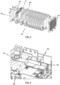
- FIG. 3 shows a cell pack 100 with a plurality of electrochemical cell assemblies 10 for use in the energy storage module 400 according to the invention.
- the electrochemical cell assemblies 10 are arranged in such a way that the first flat connecting lugs 12i and the second flat connecting lugs 12ii of the lithium ion pouch cells 11 are separated from two opposite sides of the cell pack 100 extend. In particular, the two sides are the left and right sides of the cell pack 100.
- Rods 140 are provided on an upper and a lower side, which are received or passed through holes in the cell carriers 15 of the plurality of electrochemical cell assemblies 10.
- End plates 130 are provided on a front and a rear side of the cell pack 100, which form a termination of the cell pack 100.
- the end plates 130 have associated bores through which the rods 140 can be received or passed through.
- Foam plates 150 are arranged between the end plates 130 and a first or last one of the plurality of electrochemical cell assemblies 10 according to the invention.
- the end plates 130 each have a recess, the shape and size of which is designed to accommodate the foam plate 150 at least in some areas.
- an adhesive device such as adhesive strips.
- the cell pack 100 can be assembled by applying a force to the outwardly facing end faces of the two end plates 130.
- the force to be applied is preferably between 100 Newton (N) and 400 Newton (N), but can also be selected differently from these values depending on the design of the cell package. In this way, a necessary minimum compression of the cell pack 100 can be ensured, which, for example, ensures that heat is dissipated from the cell pack 100 or that the cell pack 100 is sufficiently rigid.
- FIG. 4 shows electrical elements of the energy storage module 400 according to the invention, such as an energy storage control device 300, at least two flexible busbar connectors 310 and 320, and a shunt 330.
- the energy storage control device 300 is used to control the operation of the energy storage module 400 and has a circuit board.
- the at least two flexible busbar connectors 310 and 320 have a first flexible busbar connector 310, which is electrically conductively connected to a connection terminal of the energy storage module 400, and a second flexible busbar connector 320, which is electrically conductively connected to the cell pack 100.
- the shunt 330 further includes a first and a second surface, wherein the first or a second surface is connected to the circuit board of the energy storage controller 300 and the second or first surface is connected to the first and second flexible busbar connectors 310 and 320. This allows one very space-saving and easy-to-manufacture electrically conductive connection between the cell pack 100, the energy storage control device 300 and a connection terminal of the energy storage module 400 can be realized.
- connection of the shunt 330 to the first and second flexible busbar connectors 310 and 320, as well as the connection of the shunt 330 to the Circuit board of the energy storage control device 300 is realized via a welded connection.
- a laser beam welding process and/or an ultrasonic welding process is advantageously used for this.
- the connection of the shunt 330 to the flexible busbar connectors 310 and 320 and the circuit board of the energy storage control device 300 can take place in certain areas or over the entire area.
- FIG. 5a shows an exploded view of a contacting device 200 according to the invention.
- the contacting device 200 has a carrier 210 and four busbars 220, 220 ', 220" and 220".
- busbars 220 Of course, in this context it is conceivable that a different number of busbars 220 is provided.
- the carrier 210 has a plurality of tines 211 which have chamfered end regions 212. It can also be seen that the carrier 210 has centering devices in the form of knobs or pins, which can be accommodated at least in associated bores in the two middle busbars 220' 220".
- the carrier 210 has three areas, which are separated by webs, and thus provides three areas for fixedly receiving the bus bars 220, 220 ', 220 "and 220".
- a front bus bar 220 is accommodated in a front area
- the two middle ones Busbars 220' and 220" are accommodated in a middle area
- a rear busbar 220" is accommodated in a rear area.
- Relative information such as "front” and “rear”, also refers here to an installed state of the cell pack or the energy module.
- the front area and the rear area of the carrier 210 have areas in order to be able to accommodate a connection area 223 of the front and rear busbars 220 and 220′′′.
- each of the areas of the carrier 210 can have an adhesive strip 240 in order to connect the bus bars 220, 220 ', 220 "and 220" to the carrier 210, that is, to be able to attach them to it.
- Busbars 220 shown each have a plurality of prongs 221.
- the busbars 220 are made of different materials.
- the front busbar 220 is made of aluminum
- the adjacent middle busbar 220' is made of copper
- the other middle busbar 220" is made of aluminum
- the rear busbar 220" is made of copper.
- a bimetal plate 250 is preferably provided.
- the two materials aluminum and copper can only be welded directly with great effort, which is why the bimetal plate 250 is used, which has a first side made of aluminum and a second side made of copper.
- the side of the bimetallic plate 250 made of aluminum is welded to the busbar 220".
- the side of the bimetal plate 250, which is made of copper is welded to the bus bar 220 '.
- Threaded plates 230 are provided between the busbars 220 and the carrier 210.
- the area of the carrier 210 which receives the connection areas 223 of the busbars 220 and 220′′′, is also designed to be able to accommodate the threaded plate 230.
- FIG. 5b shows the contacting device 200 according to FIG. 3a in an assembled state.
- the busbars 220, 220', 220", 220" are accommodated in the carrier 210.
- the prongs 211 of the carrier 210 are longer than the prongs 221 of the busbars 220, 220', 220" and 220"'. This offers the advantage that only the prongs 211 of the carrier 210 have to have chamfered end regions 212. Accordingly, the busbars 220, 220', 220" and 220' or their prongs 221 are easier to manufacture.
- the webs of the carrier 210 between the front and middle and between the middle and rear areas also serve to electrically isolate the busbars 220 and 220' or the busbars 220" and 220" from one another.
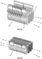
- FIGS. 6a, 6b and 6c show the energy storage module 10 in different manufacturing steps (states).
- FIG. 6a This is how it shows FIG. 6a the cell pack 100 and two contacting devices 200 before pushing on the contacting devices 200.
- FIG. 6b shows the cell pack 100 and the contacting devices 200 in a pushed-on or plugged-in state. It can be seen that the two contacting devices 200 are not or do not have to be designed identically. In particular, it can be seen that only one of the contacting devices 200 has the connection areas 223 of the busbar 220 and 220′′′. Accordingly, the carrier 210 is designed either with or without areas for receiving the connection areas 223.
- the first and second flat connecting lugs 12i and 12ii of the lithium ion pouch cells 11 also have a protective film 113, which is in an intermediate step between FIG. 6b and FIG. 6c Will get removed.
- the protective film 113 serves in particular to protect the surface of the connecting lugs 12i and 12ii.
- connection lugs 12i and 12ii of the lithium ion pouch cells 11 being bent in such a way that they enable electrical contact between the busbars 220, 220 ', 220 "and 220' and the electrochemical cell assemblies 10 .
- contact surfaces between the connecting lugs 12i and 12ii and the busbars 220, 220 ', 220 "and 220" are relatively large due to the flat design of the connecting lugs 12i, 12ii.
- the cell pack 100 and there in particular the end plates 130 also have, as in the FIG. 6a to FIG. 6c can be seen, centering devices. These can be seen in particular on the end plates 130 in the form of projections extending to the sides.
- the contacting devices 200 in particular the carrier 210, also have centering devices, which in FIG. 6a are shown, for example, in the form of struts extending parallel to the tines of the carrier.
- the carrier 210 in an upper area there is a kind of rail, which can be fastened in the upper areas of the cell carriers 15 of the multitude of electrochemical cell assemblies 10 according to the invention. This is in particular a locking device.
- the carrier 210 can be accommodated in a lower region of the cell carrier 15 of the multitude of electrochemical cell assemblies 10 according to the invention.
- This lower area can at the same time form a stop so that the contacting devices 200 can only be pushed onto the connecting lugs 12i and 12ii up to a certain position.
- the large number of electrochemical cell assemblies 10 according to the invention are provided.
- the large number of electrochemical cell assemblies 10 according to the invention are then arranged in stacks to form a cell pack 100.
- the cell pack is designed according to the structure FIG. 3 educated.
- the first and second connection lugs 12i and 12ii are arranged on opposite first and second sides of the cell pack 100.
- the at least one contacting device 200 is pushed onto the flat connecting lugs 12i and 12ii.
- the connection lugs 12i and 12ii are then bent over in such a way that the plurality of electrochemical cell assemblies 10 according to the invention can be or are electrically connected to the at least one contacting device 200.
- the connecting lugs 12i and 12ii are then welded to the at least one contacting device 200 using a multi-part welding tool 500.
- FIG. 7 shows the multi-part welding tool 500 used for assembling the energy storage module 400 according to the invention.
- the multi-part welding tool 500 consists of three main elements, a receiving device 510, an insulating plate 520, and a pressure plate 530.
- the recording device 510 has a base plate 512 with a first surface and a second surface, with position elements 513 being arranged on one of the first or second surfaces.
- the position elements 513 preferably have a substantially cuboid shape, but can also have other geometric shapes.
- the position elements 513 are further arranged at a distance from one another on the base plate 512 of the receiving device 510, so that a space is formed which enables the cell pack 100 to be received in a lateral position.
- a lateral position is a position in which the opposing first and second sides of the cell pack 100, which have the first and second connecting lugs 12i and 12ii, are arranged in a horizontal plane.
- the position elements 513 and the base plate 512 can have first recesses 514 into which fastening elements, such as screws, can be received.
- the positioning elements 513 on the base plate 512 can be aligned according to the structure of the cell pack 100.
- the position elements 513 can have second recesses 515 for receiving fastening elements 540, such as screws, which are required to clamp the cell pack 100 in the multi-part welding tool 500.
- the insulating plate 520 is positioned on the side of the cell pack 100 which is opposite the side of the cell pack 100 received by the cavity.
- the insulating plate 520 is arranged at least partially or completely on the side of the cell pack 100 which is opposite the side of the cell pack 100 received by the cavity.
- the insulating plate 520 also has recesses 521, which are aligned with the areas to be connected of the first and second flat connecting lugs 12i and 12ii and the at least one contacting device 200. This ensures that the welding process only causes the electrical damage conductive connection relevant areas of the connecting lugs 12i and 12ii and the contacting device 200 are connected to one another. In addition, areas and/or elements of the cell pack 100 or the energy storage module 400 are protected from undesirable influences that occur during the welding process.
- the insulating plate 520 can preferably be made of a plastic, such as acrylonitrile-butadiene-styrene, but other materials can also be used.
- the pressure plate 530 is placed on the insulating plate 520.
- the pressure plate also has recesses 531, which are arranged and aligned with the recesses 521 of the insulating plate 520. This ensures accessibility to the areas of the cell pack 100 to be welded.
- the pressure plate 530 also has bulges 532 on its lateral edge regions, which are provided with recesses 533.
- the recesses 533 of the bulges 532 are aligned vertically spaced with the recesses 515 of the positioning elements 513, so that the cell pack 100 is connected to the multi-part via fastening elements 540, which are accommodated in the recesses 515 and 533 of the positioning elements 513 and the bulges 532 of the pressure plate 530 Welding tool 500 is clamped.
- Positioning and bracing of the cell pack 100 in the multi-part welding tool 500 that counteracts unwanted movements can thus be achieved in a simple manner.
- only the required areas of the cell pack 100 or the energy storage module 400 are influenced by the welding process.
- the pressure plate 530 may preferably be made of a metal or a metal alloy, such as aluminum or an aluminum alloy, but manufacturing the pressure plate 530 from other materials is also possible.
- a laser beam welding process is preferably used to weld the first and second connecting lugs 12i and 12ii to the at least one contacting device 200 chosen, which advantageously supports compliance with the high requirements for the manufacturing process of the energy storage module 400 through suitable welding parameters.
Landscapes
- Chemical & Material Sciences (AREA)
- Chemical Kinetics & Catalysis (AREA)
- Electrochemistry (AREA)
- General Chemical & Material Sciences (AREA)
- Engineering & Computer Science (AREA)
- Manufacturing & Machinery (AREA)
- Inorganic Chemistry (AREA)
- Aviation & Aerospace Engineering (AREA)
- Battery Mounting, Suspending (AREA)
- Connection Of Batteries Or Terminals (AREA)
Claims (15)
- Module accumulateur d'énergie (400), lequel possède ce qui suit :- une pluralité de sous-ensembles de cellules électrochimiques (10), chaque sous-ensemble de cellules électrochimiques (10) possédant ce qui suit :- au moins deux cellules Pouch au lithium-ion (11) ;- un élément plat (13) servant à l'orientation des au moins deux cellules Pouch au lithium-ion (11) ; et- un porte-cellules (15),les au moins deux cellules Pouch au lithium-ion (11) étant disposées dans le porte-cellules (15) se trouvant en une liaison électrique entre elles, les au moins deux cellules Pouch au lithium-ion (11) possédant en outre une première et une deuxième languette de raccordement (12i, 12ii), la première et la deuxième languette de raccordement (12i, 12ii) des au moins deux cellules Pouch au lithium-ion (11) étant de configuration plane et s'étendant au moins sensiblement perpendiculairement depuis deux côtés opposés des au moins deux cellules Pouch au lithium-ion (11), et l'élément plat (13) étant disposé dans le porte-cellules (15), de préférence au centre, et l'élément plat (13) étant en outre entouré par les au moins deux cellules Pouch au lithium-ion (11) à la manière d'un sandwich et se trouvant en contact avec celles-ci au moins par certaines zones ;- un dispositif de commande d'accumulateur d'énergie (300) destiné à commander le fonctionnement de l'accumulateur d'énergie, le dispositif de commande d'accumulateur d'énergie (300) possédant un circuit imprimé ;- au moins deux connecteurs de barre-bus flexibles (310, 320) ;- un shunt (330) ; et- au moins un arrangement de mise en contact (200) servant à la mise en contact de la pluralité de sous-ensembles de cellules électrochimiques (10),la pluralité de sous-ensembles de cellules électrochimiques (10) étant disposés sous forme de pile de telle sorte qu'ils forment un paquet de cellules (100) et se trouvant au moins partiellement en liaison électrique entre eux, le shunt (330) possédant une première surface et une deuxième surface, la première surface du shunt (330) se trouvant en contact au moins par certaines zones avec les au moins deux connecteurs de barre-bus flexibles (310, 320) et la deuxième surface au moins par certaines zones avec le circuit imprimé du dispositif de commande d'accumulateur d'énergie (300), et l'au moins un arrangement de mise en contact (200) étant configuré sensiblement en forme de peigne et possédant une pluralité de dents (211, 221), et chacune de la première et de la deuxième languette de raccordement (12i, 12ii) étant respectivement accueillie entre deux dents (211, 221) voisines de l'au moins un arrangement de mise en contact (220).
- Module accumulateur d'énergie (400) selon la revendication 1,
la première et la deuxième surface du shunt (330) étant reliées au moyen d'un cordon de soudure aux au moins deux connecteurs de barre-bus flexibles (310, 320) et au circuit imprimé du dispositif de commande d'accumulateur d'énergie (300), de préférence au moyen d'un cordon de soudure par rayon laser et/ou d'un cordon de soudure par ultrasons. - Module accumulateur d'énergie (400) selon la revendication 1 ou 2,l'au moins un arrangement de mise en contact (200) possédant en outre au moins une barre-bus (220) et au moins un élément porteur (210), et l'au moins une barre-bus (220) et l'au moins un élément porteur (210) étant réalisés en forme de peigne et possédant la pluralité de dents (211, 221),l'au moins une barre-bus (220) et l'au moins un élément porteur (210) pouvant de préférence être ou étant accueillis et/ou pouvant de préférence être ou étant fixée à lui.
- Module accumulateur d'énergie (400) selon l'une des revendications 1 à 3, le paquet de cellules (100) possédant deux plaques d'extrémité (130), lesquelles sont présentes aux deux extrémités de la pluralité de sous-ensembles de cellules électrochimiques (10) disposés en forme de pile.
- Module accumulateur d'énergie (400) selon la revendication 4,
les plaques d'extrémité (130) possédant des perçages qui sont disposés et orientés à fleur avec des perçages de la pluralité de sous-ensembles de cellules électrochimiques (10), et le paquet de cellules (100) possédant en outre une pluralité de barres (140), lesquelles peuvent être ou sont guidées à travers les perçages de la pluralité de sous-ensembles de cellules électrochimiques (10) et des plaques d'extrémité (130) afin de relier celles-ci, et/ou une plaque en mousse (150) étant respectivement présente entre les sous-ensembles de cellules (10) extérieures de la pluralité de sous-ensembles de cellules électrochimiques (10) disposés en forme de pile et les plaques d'extrémité (130). - Module accumulateur d'énergie (400) selon l'une des revendications 1 à 5,un premier connecteur de barre-bus flexible (310) des au moins deux connecteurs de barre-bus flexibles (310, 320) étant relié électriquement à une borne de raccordement du module accumulateur d'énergie (400) et un deuxième connecteur de barre-bus flexible (320) des au moins deux connecteurs de barre-bus flexibles (310, 320) étant relié électriquement au paquet de cellules (100), et/oule module accumulateur d'énergie (400) possédant en outre un boîtier de module et un couvercle.
- Module accumulateur d'énergie (400) selon l'une des revendications 1 à 6, la première et la deuxième languette de raccordement (12i, 12ii) des au moins deux cellules Pouch au lithium-ion (11) étant pliables, et/ou les au moins deux cellules Pouch au lithium-ion (11) étant branchées en série ou branchées en parallèle.
- Module accumulateur d'énergie (400) selon l'une des revendications 1 à 7, l'élément plat (13) se trouvant en liaison au moins par certaines zones avec les au moins deux cellules Pouch au lithium-ion (11) par le biais d'une couche adhésive,
la couche adhésive possédant de préférence un adhésif acrylique, un adhésif à base d'époxy et/ou un ruban adhésif double face. - Module accumulateur d'énergie (400) selon l'une des revendications 1 à 8, l'élément plat (13) possédant une sonde de température (14), et/ou l'élément plat (13) étant fabriqué en un métal ou un alliage de métal.
- Procédé pour assembler un module accumulateur d'énergie (400) selon l'une des revendications 1 à 9,
le procédé comprenant les étapes suivantes :- fourniture d'une pluralité de sous-ensembles de cellules électrochimiques (10), chacun de la pluralité de sous-ensembles de cellules électrochimiques (10) possédant au moins deux cellules Pouch au lithium-ion (11), un porte-cellules (15) et un élément plat (13) servant à l'orientation des au moins deux cellules Pouch au lithium-ion (11) et chacune des au moins deux cellules Pouch au lithium-ion (11) possédant une première et une deuxième languette de raccordement (12i, 12ii) plates, lesquelles s'étendent au moins sensiblement perpendiculairement depuis deux côtés opposés des au moins deux cellules Pouch au lithium-ion (11) ;- disposition en forme de pile de la pluralité de sous-ensembles de cellules électrochimiques (10) en un paquet de cellules (100) ;- enfilement d'au moins un arrangement de mise en contact (200) sur les languettes de raccordement (12i, 12ii) de configuration plane, l'au moins un arrangement de mise en contact (200) étant configuré sensiblement en forme de peigne et possédant une pluralité de dents (211, 221), et chacune de la première et de la deuxième languette de raccordement (12i, 12ii) étant respectivement accueillie entre deux dents (211, 221) voisines de l'au moins un arrangement de mise en contact (220) ;- pliage des languettes de raccordement (12i, 12ii) de telle sorte que la pluralité de sous-ensembles de cellules électrochimiques (10) peuvent être ou sont reliés électriquement à l'au moins un arrangement de mise en contact (200) ;- soudage des languettes de raccordement (12i, 12ii) à l'au moins un arrangement de mise en contact (200) en utilisant un outil de soudage (500) en plusieurs parties ;- disposition d'un dispositif de commande d'accumulateur d'énergie (300) destiné à commander le fonctionnement de l'accumulateur d'énergie et comprenant un circuit imprimé, d'au moins deux connecteurs de barre-bus flexibles (310, 320), d'un shunt (330) et d'au moins un arrangement de mise en contact (200) en vue de la mise en contact électrique de la pluralité de sous-ensembles de cellules électrochimiques (10), le shunt (330) possédant une première surface et une deuxième surface, la première surface du shunt (330) se trouvant en contact au moins par certaines zones avec les au moins deux connecteurs de barre-bus flexibles (310, 320) et la deuxième surface au moins par certaines zones avec le circuit imprimé du dispositif de commande d'accumulateur d'énergie (300). - Procédé selon la revendication 10,
l'outil de soudage (500) en plusieurs parties possédant un arrangement d'accueil (510), une plaque isolante (520) et une plaque de pressage (530). - Procédé selon la revendication 11,l'arrangement d'accueil (510) possédant une plaque de base (512) pourvue d'éléments de positionnement (513) espacés les uns des autres, les éléments de positionnement (513) étant disposés sur la plaque de base (512) de telle sorte que le paquet de cellules (100) peut être ou est accueilli dans l'arrangement d'accueil (510) avec le premier ou le deuxième côté faisant face à la plaque de base (512), et/oula plaque isolante (520) étant positionnée au moins par certaines zones sur le deuxième ou le premier côté du paquet de cellules (100), et la plaque isolante (520) possédant des cavités (521), lesquelles sont orientées à fleur avec les zones à raccorder des languettes de raccordement (12i, 12ii) et l'au moins un arrangement de mise en contact (200), et/ou la plaque isolante (520) étant fabriquée en une matière plastique, et/ou la plaque de pressage (530) étant disposée et orientée sur la plaque isolante (520) à fleur avec celle-ci et la plaque de pressage (530) possédant en outre des cavités (531) et étant reliée à l'arrangement de serrage (510) par le biais d'une liaison vissée, et/ou la plaque de pressage (530) étant fabriquée en métal ou un alliage de métal, de préférence en aluminium ou un alliage d'aluminium.
- Procédé selon l'une des revendications 10 à 12,
l'au moins un arrangement de mise en contact (200) possédant au moins une barre-bus (220) et au moins un élément porteur (210), l'au moins une barre-bus (220) et l'au moins un élément porteur (210) étant réalisés en forme de peigne et possédant la pluralité de dents (211, 221). - Procédé selon l'une des revendications 10 à 13,
le paquet de cellules (100) possédant deux plaques d'extrémité (130), lesquelles sont présentes aux deux extrémités de la pluralité de sous-ensembles de cellules électrochimiques (10) disposés en forme de pile. - Procédé selon l'une des revendications 10 à 14,
le soudage des languettes de raccordement (12i, 12ii) à l'au moins un arrangement de mise en contact (200) étant effectué au moyen d'un procédé de soudage par rayon laser.
Applications Claiming Priority (2)
| Application Number | Priority Date | Filing Date | Title |
|---|---|---|---|
| US201762513597P | 2017-06-01 | 2017-06-01 | |
| PCT/EP2018/064509 WO2018220197A2 (fr) | 2017-06-01 | 2018-06-01 | Ensemble de cellules électrochimiques, module d'accumulation d'énergie et procédé pour l'assemblage de ceux-ci |
Publications (2)
| Publication Number | Publication Date |
|---|---|
| EP3631877A2 EP3631877A2 (fr) | 2020-04-08 |
| EP3631877B1 true EP3631877B1 (fr) | 2023-10-11 |
Family
ID=62748899
Family Applications (1)
| Application Number | Title | Priority Date | Filing Date |
|---|---|---|---|
| EP18734079.9A Active EP3631877B1 (fr) | 2017-06-01 | 2018-06-01 | Module d'accumulation d'énergie et procédé pour l'assemblage de ceux-ci |
Country Status (4)
| Country | Link |
|---|---|
| US (2) | US11342638B2 (fr) |
| EP (1) | EP3631877B1 (fr) |
| CN (1) | CN111316464A (fr) |
| WO (1) | WO2018220197A2 (fr) |
Families Citing this family (3)
| Publication number | Priority date | Publication date | Assignee | Title |
|---|---|---|---|---|
| KR20200097510A (ko) * | 2019-02-08 | 2020-08-19 | 에스케이이노베이션 주식회사 | 배터리 모듈 및 이의 제조방법 |
| US11984611B2 (en) | 2021-08-17 | 2024-05-14 | Beta Air, Llc | Stack battery pack for electric vertical take-off and landing aircraft |
| DE102022116265A1 (de) | 2022-06-29 | 2024-01-04 | Webasto SE | Verfahren zum Herstellen einer Batterieanordnung und Montagevorrichtung |
Citations (2)
| Publication number | Priority date | Publication date | Assignee | Title |
|---|---|---|---|---|
| WO2010031857A2 (fr) * | 2008-09-18 | 2010-03-25 | Magna Steyr Fahrzeugtechnik Ag & Co Kg | Unité de refroidissement |
| WO2018065580A1 (fr) * | 2016-10-06 | 2018-04-12 | Johnson Controls Advanced Power Solutions Gmbh | Module de stockage d'énergie et procédé d'assemblage |
Family Cites Families (7)
| Publication number | Priority date | Publication date | Assignee | Title |
|---|---|---|---|---|
| KR101054833B1 (ko) | 2007-10-29 | 2011-08-05 | 에스케이이노베이션 주식회사 | 리튬 2차 전지 단위 셋 및 리튬 2차 전지 셋 |
| KR101301138B1 (ko) * | 2010-02-11 | 2013-09-03 | 주식회사 엘지화학 | 전극단자의 레이저 용접 장치 및 용접 방법 |
| US9225035B1 (en) * | 2012-06-06 | 2015-12-29 | KleenSpeed Technologies Inc. | Low profile battery module and improved thermal interface |
| US9496588B2 (en) * | 2013-07-30 | 2016-11-15 | Johnson Controls Technology Company | Battery module with cooling features |
| US9660244B2 (en) * | 2013-09-06 | 2017-05-23 | Johnson Controls Technology Company | System and method for establishing connections of a battery module |
| KR20150115250A (ko) | 2014-04-03 | 2015-10-14 | 주식회사 엘지화학 | 내부 텐션-바를 포함하는 배터리 팩 |
| CN204747845U (zh) | 2015-02-03 | 2015-11-11 | 合肥国轩高科动力能源股份公司 | 一种用于自动化焊接的电池组夹具 |
-
2018
- 2018-06-01 WO PCT/EP2018/064509 patent/WO2018220197A2/fr unknown
- 2018-06-01 EP EP18734079.9A patent/EP3631877B1/fr active Active
- 2018-06-01 CN CN201880048388.9A patent/CN111316464A/zh active Pending
- 2018-06-01 US US16/616,552 patent/US11342638B2/en active Active
-
2022
- 2022-04-20 US US17/724,675 patent/US20220247042A1/en active Pending
Patent Citations (2)
| Publication number | Priority date | Publication date | Assignee | Title |
|---|---|---|---|---|
| WO2010031857A2 (fr) * | 2008-09-18 | 2010-03-25 | Magna Steyr Fahrzeugtechnik Ag & Co Kg | Unité de refroidissement |
| WO2018065580A1 (fr) * | 2016-10-06 | 2018-04-12 | Johnson Controls Advanced Power Solutions Gmbh | Module de stockage d'énergie et procédé d'assemblage |
Also Published As
| Publication number | Publication date |
|---|---|
| US20220247042A1 (en) | 2022-08-04 |
| US11342638B2 (en) | 2022-05-24 |
| WO2018220197A3 (fr) | 2019-04-11 |
| US20210167472A1 (en) | 2021-06-03 |
| EP3631877A2 (fr) | 2020-04-08 |
| WO2018220197A2 (fr) | 2018-12-06 |
| CN111316464A (zh) | 2020-06-19 |
Similar Documents
| Publication | Publication Date | Title |
|---|---|---|
| DE102016118977B4 (de) | Energiespeichermodul und Verfahren zum Zusammenbau | |
| EP2692001B1 (fr) | Batterie pour véhicule automobile | |
| DE102011013845B4 (de) | Batteriemodul und vorrichtung sowie verfahren zum zusammenbauen eines batteriemoduls | |
| WO2018083303A1 (fr) | Système de mise en contact de cellules pour dispositif électrochimique | |
| EP2715833B1 (fr) | Module d'accumulation d'énergie composé de plusieurs cellules d'accumulation prismatiques | |
| EP3631877B1 (fr) | Module d'accumulation d'énergie et procédé pour l'assemblage de ceux-ci | |
| EP2740169B1 (fr) | Cellule unitaire pour batterie et batterie | |
| DE102013220044B4 (de) | Zellkontaktierungssystem für eine elektrochemische Vorrichtung und Verfahren zum Herstellen eines Zellkontaktierungssystems | |
| EP2593982B1 (fr) | Module d'éléments de batterie, batterie et véhicule à moteur | |
| DE112014006079B4 (de) | Verfahren zum Herstellen eines Batterieverdrahtungsmoduls | |
| DE102015113374A1 (de) | Integration einer spannungserfassungs-leiterbahnsicherung in eine batterieverbindungsplatine | |
| DE102013021549A1 (de) | Hochvoltbatterie | |
| EP2697842B2 (fr) | Système comprenant un module de stockage d'énergie constitué de plusieurs cellules de stockage prismatiques et procédé de fabrication d'une plaque d'extrémité du module de stockage d'énergie | |
| EP2735039B1 (fr) | Système de mise en contact électrique des éléments d'un accumulateur d'énergie | |
| DE102009035461A1 (de) | Batterie mit einer Vielzahl von Batterieeinzelzellen | |
| EP2692000B1 (fr) | Batterie pour véhicule automobile et procédé de production associé | |
| DE102011109240A1 (de) | Verfahren zum elektischen Verbinden von Kontaktelementen | |
| DE102011109216A1 (de) | Rahmenelement für einen Zellverbund | |
| DE102008050437A1 (de) | Skalierbare Kraftfahrzeugbatterie | |
| WO2015074735A1 (fr) | Batterie comportant une pluralité d'éléments de batterie à pôles reliés par des éléments de liaison | |
| DE102010013031A1 (de) | Batterie mit einem Zellenstapel von Batterieeinzelzellen | |
| DE102019118392A1 (de) | Batterie für ein Kraftfahrzeug und Kraftfahrzeug | |
| DE202021004343U1 (de) | Batteriemodul und Batteriepack, das dieses Modul einschließt | |
| AT526615B1 (de) | Zellenmodul mit wiederaufladbaren Zellen | |
| DE102012018088A1 (de) | Vorrichtung zum elektrischen Kontaktieren von prismatischen Batterieeinzelzellen |
Legal Events
| Date | Code | Title | Description |
|---|---|---|---|
| STAA | Information on the status of an ep patent application or granted ep patent |
Free format text: STATUS: UNKNOWN |
|
| STAA | Information on the status of an ep patent application or granted ep patent |
Free format text: STATUS: THE INTERNATIONAL PUBLICATION HAS BEEN MADE |
|
| PUAI | Public reference made under article 153(3) epc to a published international application that has entered the european phase |
Free format text: ORIGINAL CODE: 0009012 |
|
| STAA | Information on the status of an ep patent application or granted ep patent |
Free format text: STATUS: REQUEST FOR EXAMINATION WAS MADE |
|
| 17P | Request for examination filed |
Effective date: 20191227 |
|
| AK | Designated contracting states |
Kind code of ref document: A2 Designated state(s): AL AT BE BG CH CY CZ DE DK EE ES FI FR GB GR HR HU IE IS IT LI LT LU LV MC MK MT NL NO PL PT RO RS SE SI SK SM TR |
|
| AX | Request for extension of the european patent |
Extension state: BA ME |
|
| DAV | Request for validation of the european patent (deleted) | ||
| DAX | Request for extension of the european patent (deleted) | ||
| REG | Reference to a national code |
Ref document number: 502018013441 Country of ref document: DE Ref country code: DE Ref legal event code: R079 Free format text: PREVIOUS MAIN CLASS: H01M0002100000 Ipc: H01M0050211000 |
|
| GRAP | Despatch of communication of intention to grant a patent |
Free format text: ORIGINAL CODE: EPIDOSNIGR1 |
|
| STAA | Information on the status of an ep patent application or granted ep patent |
Free format text: STATUS: GRANT OF PATENT IS INTENDED |
|
| RIC1 | Information provided on ipc code assigned before grant |
Ipc: H01M 50/262 20210101ALI20230406BHEP Ipc: H01M 50/522 20210101ALI20230406BHEP Ipc: H01M 50/516 20210101ALI20230406BHEP Ipc: H01M 50/507 20210101ALI20230406BHEP Ipc: H01M 50/291 20210101ALI20230406BHEP Ipc: H01M 50/284 20210101ALI20230406BHEP Ipc: H01M 50/271 20210101ALI20230406BHEP Ipc: H01M 50/227 20210101ALI20230406BHEP Ipc: H01M 50/211 20210101AFI20230406BHEP |
|
| INTG | Intention to grant announced |
Effective date: 20230425 |
|
| GRAS | Grant fee paid |
Free format text: ORIGINAL CODE: EPIDOSNIGR3 |
|
| GRAA | (expected) grant |
Free format text: ORIGINAL CODE: 0009210 |
|
| STAA | Information on the status of an ep patent application or granted ep patent |
Free format text: STATUS: THE PATENT HAS BEEN GRANTED |
|
| AK | Designated contracting states |
Kind code of ref document: B1 Designated state(s): AL AT BE BG CH CY CZ DE DK EE ES FI FR GB GR HR HU IE IS IT LI LT LU LV MC MK MT NL NO PL PT RO RS SE SI SK SM TR |
|
| REG | Reference to a national code |
Ref country code: GB Ref legal event code: FG4D Free format text: NOT ENGLISH |
|
| REG | Reference to a national code |
Ref country code: CH Ref legal event code: EP |
|
| REG | Reference to a national code |
Ref country code: DE Ref legal event code: R096 Ref document number: 502018013441 Country of ref document: DE |
|
| REG | Reference to a national code |
Ref country code: IE Ref legal event code: FG4D Free format text: LANGUAGE OF EP DOCUMENT: GERMAN |
|
| REG | Reference to a national code |
Ref country code: LT Ref legal event code: MG9D |
|
| REG | Reference to a national code |
Ref country code: NL Ref legal event code: MP Effective date: 20231011 |
|
| PG25 | Lapsed in a contracting state [announced via postgrant information from national office to epo] |
Ref country code: NL Free format text: LAPSE BECAUSE OF FAILURE TO SUBMIT A TRANSLATION OF THE DESCRIPTION OR TO PAY THE FEE WITHIN THE PRESCRIBED TIME-LIMIT Effective date: 20231011 |
|
| PG25 | Lapsed in a contracting state [announced via postgrant information from national office to epo] |
Ref country code: GR Free format text: LAPSE BECAUSE OF FAILURE TO SUBMIT A TRANSLATION OF THE DESCRIPTION OR TO PAY THE FEE WITHIN THE PRESCRIBED TIME-LIMIT Effective date: 20240112 |
|
| PG25 | Lapsed in a contracting state [announced via postgrant information from national office to epo] |
Ref country code: IS Free format text: LAPSE BECAUSE OF FAILURE TO SUBMIT A TRANSLATION OF THE DESCRIPTION OR TO PAY THE FEE WITHIN THE PRESCRIBED TIME-LIMIT Effective date: 20240211 |
|
| PG25 | Lapsed in a contracting state [announced via postgrant information from national office to epo] |
Ref country code: LT Free format text: LAPSE BECAUSE OF FAILURE TO SUBMIT A TRANSLATION OF THE DESCRIPTION OR TO PAY THE FEE WITHIN THE PRESCRIBED TIME-LIMIT Effective date: 20231011 |
|
| PG25 | Lapsed in a contracting state [announced via postgrant information from national office to epo] |
Ref country code: ES Free format text: LAPSE BECAUSE OF FAILURE TO SUBMIT A TRANSLATION OF THE DESCRIPTION OR TO PAY THE FEE WITHIN THE PRESCRIBED TIME-LIMIT Effective date: 20231011 |
|
| PG25 | Lapsed in a contracting state [announced via postgrant information from national office to epo] |
Ref country code: LT Free format text: LAPSE BECAUSE OF FAILURE TO SUBMIT A TRANSLATION OF THE DESCRIPTION OR TO PAY THE FEE WITHIN THE PRESCRIBED TIME-LIMIT Effective date: 20231011 Ref country code: IS Free format text: LAPSE BECAUSE OF FAILURE TO SUBMIT A TRANSLATION OF THE DESCRIPTION OR TO PAY THE FEE WITHIN THE PRESCRIBED TIME-LIMIT Effective date: 20240211 Ref country code: GR Free format text: LAPSE BECAUSE OF FAILURE TO SUBMIT A TRANSLATION OF THE DESCRIPTION OR TO PAY THE FEE WITHIN THE PRESCRIBED TIME-LIMIT Effective date: 20240112 Ref country code: ES Free format text: LAPSE BECAUSE OF FAILURE TO SUBMIT A TRANSLATION OF THE DESCRIPTION OR TO PAY THE FEE WITHIN THE PRESCRIBED TIME-LIMIT Effective date: 20231011 Ref country code: BG Free format text: LAPSE BECAUSE OF FAILURE TO SUBMIT A TRANSLATION OF THE DESCRIPTION OR TO PAY THE FEE WITHIN THE PRESCRIBED TIME-LIMIT Effective date: 20240111 Ref country code: PT Free format text: LAPSE BECAUSE OF FAILURE TO SUBMIT A TRANSLATION OF THE DESCRIPTION OR TO PAY THE FEE WITHIN THE PRESCRIBED TIME-LIMIT Effective date: 20240212 |
|
| PG25 | Lapsed in a contracting state [announced via postgrant information from national office to epo] |
Ref country code: SE Free format text: LAPSE BECAUSE OF FAILURE TO SUBMIT A TRANSLATION OF THE DESCRIPTION OR TO PAY THE FEE WITHIN THE PRESCRIBED TIME-LIMIT Effective date: 20231011 Ref country code: RS Free format text: LAPSE BECAUSE OF FAILURE TO SUBMIT A TRANSLATION OF THE DESCRIPTION OR TO PAY THE FEE WITHIN THE PRESCRIBED TIME-LIMIT Effective date: 20231011 Ref country code: PL Free format text: LAPSE BECAUSE OF FAILURE TO SUBMIT A TRANSLATION OF THE DESCRIPTION OR TO PAY THE FEE WITHIN THE PRESCRIBED TIME-LIMIT Effective date: 20231011 Ref country code: NO Free format text: LAPSE BECAUSE OF FAILURE TO SUBMIT A TRANSLATION OF THE DESCRIPTION OR TO PAY THE FEE WITHIN THE PRESCRIBED TIME-LIMIT Effective date: 20240111 Ref country code: LV Free format text: LAPSE BECAUSE OF FAILURE TO SUBMIT A TRANSLATION OF THE DESCRIPTION OR TO PAY THE FEE WITHIN THE PRESCRIBED TIME-LIMIT Effective date: 20231011 Ref country code: HR Free format text: LAPSE BECAUSE OF FAILURE TO SUBMIT A TRANSLATION OF THE DESCRIPTION OR TO PAY THE FEE WITHIN THE PRESCRIBED TIME-LIMIT Effective date: 20231011 |
|
| PGFP | Annual fee paid to national office [announced via postgrant information from national office to epo] |
Ref country code: GB Payment date: 20240627 Year of fee payment: 7 |
|
| PGFP | Annual fee paid to national office [announced via postgrant information from national office to epo] |
Ref country code: DE Payment date: 20240627 Year of fee payment: 7 |
|
| PG25 | Lapsed in a contracting state [announced via postgrant information from national office to epo] |
Ref country code: DK Free format text: LAPSE BECAUSE OF FAILURE TO SUBMIT A TRANSLATION OF THE DESCRIPTION OR TO PAY THE FEE WITHIN THE PRESCRIBED TIME-LIMIT Effective date: 20231011 |
|
| REG | Reference to a national code |
Ref country code: DE Ref legal event code: R097 Ref document number: 502018013441 Country of ref document: DE |
|
| PG25 | Lapsed in a contracting state [announced via postgrant information from national office to epo] |
Ref country code: CZ Free format text: LAPSE BECAUSE OF FAILURE TO SUBMIT A TRANSLATION OF THE DESCRIPTION OR TO PAY THE FEE WITHIN THE PRESCRIBED TIME-LIMIT Effective date: 20231011 |
|
| PG25 | Lapsed in a contracting state [announced via postgrant information from national office to epo] |
Ref country code: SK Free format text: LAPSE BECAUSE OF FAILURE TO SUBMIT A TRANSLATION OF THE DESCRIPTION OR TO PAY THE FEE WITHIN THE PRESCRIBED TIME-LIMIT Effective date: 20231011 |
|
| PG25 | Lapsed in a contracting state [announced via postgrant information from national office to epo] |
Ref country code: SM Free format text: LAPSE BECAUSE OF FAILURE TO SUBMIT A TRANSLATION OF THE DESCRIPTION OR TO PAY THE FEE WITHIN THE PRESCRIBED TIME-LIMIT Effective date: 20231011 Ref country code: SK Free format text: LAPSE BECAUSE OF FAILURE TO SUBMIT A TRANSLATION OF THE DESCRIPTION OR TO PAY THE FEE WITHIN THE PRESCRIBED TIME-LIMIT Effective date: 20231011 Ref country code: RO Free format text: LAPSE BECAUSE OF FAILURE TO SUBMIT A TRANSLATION OF THE DESCRIPTION OR TO PAY THE FEE WITHIN THE PRESCRIBED TIME-LIMIT Effective date: 20231011 Ref country code: IT Free format text: LAPSE BECAUSE OF FAILURE TO SUBMIT A TRANSLATION OF THE DESCRIPTION OR TO PAY THE FEE WITHIN THE PRESCRIBED TIME-LIMIT Effective date: 20231011 Ref country code: EE Free format text: LAPSE BECAUSE OF FAILURE TO SUBMIT A TRANSLATION OF THE DESCRIPTION OR TO PAY THE FEE WITHIN THE PRESCRIBED TIME-LIMIT Effective date: 20231011 Ref country code: DK Free format text: LAPSE BECAUSE OF FAILURE TO SUBMIT A TRANSLATION OF THE DESCRIPTION OR TO PAY THE FEE WITHIN THE PRESCRIBED TIME-LIMIT Effective date: 20231011 Ref country code: CZ Free format text: LAPSE BECAUSE OF FAILURE TO SUBMIT A TRANSLATION OF THE DESCRIPTION OR TO PAY THE FEE WITHIN THE PRESCRIBED TIME-LIMIT Effective date: 20231011 |
|
| PGFP | Annual fee paid to national office [announced via postgrant information from national office to epo] |
Ref country code: FR Payment date: 20240625 Year of fee payment: 7 |
|
| PLBE | No opposition filed within time limit |
Free format text: ORIGINAL CODE: 0009261 |
|
| STAA | Information on the status of an ep patent application or granted ep patent |
Free format text: STATUS: NO OPPOSITION FILED WITHIN TIME LIMIT |
|
| 26N | No opposition filed |
Effective date: 20240712 |