EP3631877B1 - Energy storage module and method for the assembly thereof - Google Patents
Energy storage module and method for the assembly thereof Download PDFInfo
- Publication number
- EP3631877B1 EP3631877B1 EP18734079.9A EP18734079A EP3631877B1 EP 3631877 B1 EP3631877 B1 EP 3631877B1 EP 18734079 A EP18734079 A EP 18734079A EP 3631877 B1 EP3631877 B1 EP 3631877B1
- Authority
- EP
- European Patent Office
- Prior art keywords
- energy store
- multiplicity
- lithium
- electrochemical cell
- pouch cells
- Prior art date
- Legal status (The legal status is an assumption and is not a legal conclusion. Google has not performed a legal analysis and makes no representation as to the accuracy of the status listed.)
- Active
Links
- 238000000034 method Methods 0.000 title claims description 31
- 238000004146 energy storage Methods 0.000 title description 65
- HBBGRARXTFLTSG-UHFFFAOYSA-N Lithium ion Chemical compound [Li+] HBBGRARXTFLTSG-UHFFFAOYSA-N 0.000 claims description 54
- 230000000712 assembly Effects 0.000 claims description 54
- 238000000429 assembly Methods 0.000 claims description 54
- 229910001416 lithium ion Inorganic materials 0.000 claims description 54
- 238000003466 welding Methods 0.000 claims description 39
- 239000006260 foam Substances 0.000 claims description 9
- 229910052782 aluminium Inorganic materials 0.000 claims description 8
- XAGFODPZIPBFFR-UHFFFAOYSA-N aluminium Chemical compound [Al] XAGFODPZIPBFFR-UHFFFAOYSA-N 0.000 claims description 8
- 229910052751 metal Inorganic materials 0.000 claims description 7
- 239000002184 metal Substances 0.000 claims description 7
- 229910001092 metal group alloy Inorganic materials 0.000 claims description 7
- 229920003023 plastic Polymers 0.000 claims description 5
- 239000004033 plastic Substances 0.000 claims description 5
- 229910000838 Al alloy Inorganic materials 0.000 claims description 4
- 239000003522 acrylic cement Substances 0.000 claims description 3
- 239000012790 adhesive layer Substances 0.000 claims description 3
- 239000002390 adhesive tape Substances 0.000 claims description 3
- 229920006332 epoxy adhesive Polymers 0.000 claims description 3
- 238000005452 bending Methods 0.000 claims description 2
- 239000004411 aluminium Substances 0.000 claims 1
- 238000004519 manufacturing process Methods 0.000 description 20
- 239000000853 adhesive Substances 0.000 description 9
- 230000001070 adhesive effect Effects 0.000 description 9
- 238000013461 design Methods 0.000 description 8
- 238000011161 development Methods 0.000 description 8
- 230000018109 developmental process Effects 0.000 description 8
- 239000000463 material Substances 0.000 description 8
- RYGMFSIKBFXOCR-UHFFFAOYSA-N Copper Chemical compound [Cu] RYGMFSIKBFXOCR-UHFFFAOYSA-N 0.000 description 5
- 229910052802 copper Inorganic materials 0.000 description 5
- 239000010949 copper Substances 0.000 description 5
- 239000007858 starting material Substances 0.000 description 5
- XECAHXYUAAWDEL-UHFFFAOYSA-N acrylonitrile butadiene styrene Chemical compound C=CC=C.C=CC#N.C=CC1=CC=CC=C1 XECAHXYUAAWDEL-UHFFFAOYSA-N 0.000 description 4
- 229920000122 acrylonitrile butadiene styrene Polymers 0.000 description 4
- 239000004676 acrylonitrile butadiene styrene Substances 0.000 description 4
- -1 polyethylene terephthalate Polymers 0.000 description 4
- 238000002485 combustion reaction Methods 0.000 description 3
- 238000009434 installation Methods 0.000 description 3
- 230000001681 protective effect Effects 0.000 description 3
- 229930040373 Paraformaldehyde Natural products 0.000 description 2
- 239000004952 Polyamide Substances 0.000 description 2
- 230000015572 biosynthetic process Effects 0.000 description 2
- 239000000969 carrier Substances 0.000 description 2
- 229920001577 copolymer Polymers 0.000 description 2
- 230000000694 effects Effects 0.000 description 2
- 238000005516 engineering process Methods 0.000 description 2
- 229920002647 polyamide Polymers 0.000 description 2
- 229920000515 polycarbonate Polymers 0.000 description 2
- 239000004417 polycarbonate Substances 0.000 description 2
- 229920000139 polyethylene terephthalate Polymers 0.000 description 2
- 239000005020 polyethylene terephthalate Substances 0.000 description 2
- 229920006324 polyoxymethylene Polymers 0.000 description 2
- 229920000915 polyvinyl chloride Polymers 0.000 description 2
- 239000004800 polyvinyl chloride Substances 0.000 description 2
- 238000007639 printing Methods 0.000 description 2
- 239000002253 acid Substances 0.000 description 1
- 230000006978 adaptation Effects 0.000 description 1
- 239000003795 chemical substances by application Substances 0.000 description 1
- 230000006835 compression Effects 0.000 description 1
- 238000007906 compression Methods 0.000 description 1
- 239000004020 conductor Substances 0.000 description 1
- 238000013016 damping Methods 0.000 description 1
- 230000001419 dependent effect Effects 0.000 description 1
- 230000005611 electricity Effects 0.000 description 1
- 238000009413 insulation Methods 0.000 description 1
- 238000005304 joining Methods 0.000 description 1
- 238000011031 large-scale manufacturing process Methods 0.000 description 1
- 238000012423 maintenance Methods 0.000 description 1
- 239000012811 non-conductive material Substances 0.000 description 1
- 238000012545 processing Methods 0.000 description 1
- 230000035939 shock Effects 0.000 description 1
- 238000003860 storage Methods 0.000 description 1
- 238000009423 ventilation Methods 0.000 description 1
Images


Classifications
-
- H—ELECTRICITY
- H01—ELECTRIC ELEMENTS
- H01M—PROCESSES OR MEANS, e.g. BATTERIES, FOR THE DIRECT CONVERSION OF CHEMICAL ENERGY INTO ELECTRICAL ENERGY
- H01M50/00—Constructional details or processes of manufacture of the non-active parts of electrochemical cells other than fuel cells, e.g. hybrid cells
- H01M50/50—Current conducting connections for cells or batteries
- H01M50/502—Interconnectors for connecting terminals of adjacent batteries; Interconnectors for connecting cells outside a battery casing
- H01M50/521—Interconnectors for connecting terminals of adjacent batteries; Interconnectors for connecting cells outside a battery casing characterised by the material
- H01M50/522—Inorganic material
-
- H—ELECTRICITY
- H01—ELECTRIC ELEMENTS
- H01M—PROCESSES OR MEANS, e.g. BATTERIES, FOR THE DIRECT CONVERSION OF CHEMICAL ENERGY INTO ELECTRICAL ENERGY
- H01M50/00—Constructional details or processes of manufacture of the non-active parts of electrochemical cells other than fuel cells, e.g. hybrid cells
- H01M50/50—Current conducting connections for cells or batteries
- H01M50/543—Terminals
- H01M50/552—Terminals characterised by their shape
- H01M50/553—Terminals adapted for prismatic, pouch or rectangular cells
-
- H—ELECTRICITY
- H01—ELECTRIC ELEMENTS
- H01M—PROCESSES OR MEANS, e.g. BATTERIES, FOR THE DIRECT CONVERSION OF CHEMICAL ENERGY INTO ELECTRICAL ENERGY
- H01M10/00—Secondary cells; Manufacture thereof
- H01M10/42—Methods or arrangements for servicing or maintenance of secondary cells or secondary half-cells
- H01M10/48—Accumulators combined with arrangements for measuring, testing or indicating the condition of cells, e.g. the level or density of the electrolyte
- H01M10/486—Accumulators combined with arrangements for measuring, testing or indicating the condition of cells, e.g. the level or density of the electrolyte for measuring temperature
-
- H—ELECTRICITY
- H01—ELECTRIC ELEMENTS
- H01M—PROCESSES OR MEANS, e.g. BATTERIES, FOR THE DIRECT CONVERSION OF CHEMICAL ENERGY INTO ELECTRICAL ENERGY
- H01M50/00—Constructional details or processes of manufacture of the non-active parts of electrochemical cells other than fuel cells, e.g. hybrid cells
- H01M50/20—Mountings; Secondary casings or frames; Racks, modules or packs; Suspension devices; Shock absorbers; Transport or carrying devices; Holders
- H01M50/204—Racks, modules or packs for multiple batteries or multiple cells
- H01M50/207—Racks, modules or packs for multiple batteries or multiple cells characterised by their shape
- H01M50/211—Racks, modules or packs for multiple batteries or multiple cells characterised by their shape adapted for pouch cells
-
- H—ELECTRICITY
- H01—ELECTRIC ELEMENTS
- H01M—PROCESSES OR MEANS, e.g. BATTERIES, FOR THE DIRECT CONVERSION OF CHEMICAL ENERGY INTO ELECTRICAL ENERGY
- H01M50/00—Constructional details or processes of manufacture of the non-active parts of electrochemical cells other than fuel cells, e.g. hybrid cells
- H01M50/20—Mountings; Secondary casings or frames; Racks, modules or packs; Suspension devices; Shock absorbers; Transport or carrying devices; Holders
- H01M50/218—Mountings; Secondary casings or frames; Racks, modules or packs; Suspension devices; Shock absorbers; Transport or carrying devices; Holders characterised by the material
- H01M50/22—Mountings; Secondary casings or frames; Racks, modules or packs; Suspension devices; Shock absorbers; Transport or carrying devices; Holders characterised by the material of the casings or racks
- H01M50/227—Organic material
-
- H—ELECTRICITY
- H01—ELECTRIC ELEMENTS
- H01M—PROCESSES OR MEANS, e.g. BATTERIES, FOR THE DIRECT CONVERSION OF CHEMICAL ENERGY INTO ELECTRICAL ENERGY
- H01M50/00—Constructional details or processes of manufacture of the non-active parts of electrochemical cells other than fuel cells, e.g. hybrid cells
- H01M50/20—Mountings; Secondary casings or frames; Racks, modules or packs; Suspension devices; Shock absorbers; Transport or carrying devices; Holders
- H01M50/249—Mountings; Secondary casings or frames; Racks, modules or packs; Suspension devices; Shock absorbers; Transport or carrying devices; Holders specially adapted for aircraft or vehicles, e.g. cars or trains
-
- H—ELECTRICITY
- H01—ELECTRIC ELEMENTS
- H01M—PROCESSES OR MEANS, e.g. BATTERIES, FOR THE DIRECT CONVERSION OF CHEMICAL ENERGY INTO ELECTRICAL ENERGY
- H01M50/00—Constructional details or processes of manufacture of the non-active parts of electrochemical cells other than fuel cells, e.g. hybrid cells
- H01M50/20—Mountings; Secondary casings or frames; Racks, modules or packs; Suspension devices; Shock absorbers; Transport or carrying devices; Holders
- H01M50/262—Mountings; Secondary casings or frames; Racks, modules or packs; Suspension devices; Shock absorbers; Transport or carrying devices; Holders with fastening means, e.g. locks
-
- H—ELECTRICITY
- H01—ELECTRIC ELEMENTS
- H01M—PROCESSES OR MEANS, e.g. BATTERIES, FOR THE DIRECT CONVERSION OF CHEMICAL ENERGY INTO ELECTRICAL ENERGY
- H01M50/00—Constructional details or processes of manufacture of the non-active parts of electrochemical cells other than fuel cells, e.g. hybrid cells
- H01M50/20—Mountings; Secondary casings or frames; Racks, modules or packs; Suspension devices; Shock absorbers; Transport or carrying devices; Holders
- H01M50/271—Lids or covers for the racks or secondary casings
-
- H—ELECTRICITY
- H01—ELECTRIC ELEMENTS
- H01M—PROCESSES OR MEANS, e.g. BATTERIES, FOR THE DIRECT CONVERSION OF CHEMICAL ENERGY INTO ELECTRICAL ENERGY
- H01M50/00—Constructional details or processes of manufacture of the non-active parts of electrochemical cells other than fuel cells, e.g. hybrid cells
- H01M50/20—Mountings; Secondary casings or frames; Racks, modules or packs; Suspension devices; Shock absorbers; Transport or carrying devices; Holders
- H01M50/284—Mountings; Secondary casings or frames; Racks, modules or packs; Suspension devices; Shock absorbers; Transport or carrying devices; Holders with incorporated circuit boards, e.g. printed circuit boards [PCB]
-
- H—ELECTRICITY
- H01—ELECTRIC ELEMENTS
- H01M—PROCESSES OR MEANS, e.g. BATTERIES, FOR THE DIRECT CONVERSION OF CHEMICAL ENERGY INTO ELECTRICAL ENERGY
- H01M50/00—Constructional details or processes of manufacture of the non-active parts of electrochemical cells other than fuel cells, e.g. hybrid cells
- H01M50/20—Mountings; Secondary casings or frames; Racks, modules or packs; Suspension devices; Shock absorbers; Transport or carrying devices; Holders
- H01M50/289—Mountings; Secondary casings or frames; Racks, modules or packs; Suspension devices; Shock absorbers; Transport or carrying devices; Holders characterised by spacing elements or positioning means within frames, racks or packs
- H01M50/291—Mountings; Secondary casings or frames; Racks, modules or packs; Suspension devices; Shock absorbers; Transport or carrying devices; Holders characterised by spacing elements or positioning means within frames, racks or packs characterised by their shape
-
- H—ELECTRICITY
- H01—ELECTRIC ELEMENTS
- H01M—PROCESSES OR MEANS, e.g. BATTERIES, FOR THE DIRECT CONVERSION OF CHEMICAL ENERGY INTO ELECTRICAL ENERGY
- H01M50/00—Constructional details or processes of manufacture of the non-active parts of electrochemical cells other than fuel cells, e.g. hybrid cells
- H01M50/50—Current conducting connections for cells or batteries
- H01M50/502—Interconnectors for connecting terminals of adjacent batteries; Interconnectors for connecting cells outside a battery casing
- H01M50/507—Interconnectors for connecting terminals of adjacent batteries; Interconnectors for connecting cells outside a battery casing comprising an arrangement of two or more busbars within a container structure, e.g. busbar modules
-
- H—ELECTRICITY
- H01—ELECTRIC ELEMENTS
- H01M—PROCESSES OR MEANS, e.g. BATTERIES, FOR THE DIRECT CONVERSION OF CHEMICAL ENERGY INTO ELECTRICAL ENERGY
- H01M50/00—Constructional details or processes of manufacture of the non-active parts of electrochemical cells other than fuel cells, e.g. hybrid cells
- H01M50/50—Current conducting connections for cells or batteries
- H01M50/502—Interconnectors for connecting terminals of adjacent batteries; Interconnectors for connecting cells outside a battery casing
- H01M50/514—Methods for interconnecting adjacent batteries or cells
- H01M50/516—Methods for interconnecting adjacent batteries or cells by welding, soldering or brazing
-
- H—ELECTRICITY
- H01—ELECTRIC ELEMENTS
- H01M—PROCESSES OR MEANS, e.g. BATTERIES, FOR THE DIRECT CONVERSION OF CHEMICAL ENERGY INTO ELECTRICAL ENERGY
- H01M50/00—Constructional details or processes of manufacture of the non-active parts of electrochemical cells other than fuel cells, e.g. hybrid cells
- H01M50/50—Current conducting connections for cells or batteries
- H01M50/543—Terminals
- H01M50/564—Terminals characterised by their manufacturing process
- H01M50/566—Terminals characterised by their manufacturing process by welding, soldering or brazing
-
- H—ELECTRICITY
- H01—ELECTRIC ELEMENTS
- H01M—PROCESSES OR MEANS, e.g. BATTERIES, FOR THE DIRECT CONVERSION OF CHEMICAL ENERGY INTO ELECTRICAL ENERGY
- H01M2220/00—Batteries for particular applications
- H01M2220/20—Batteries in motive systems, e.g. vehicle, ship, plane
-
- Y—GENERAL TAGGING OF NEW TECHNOLOGICAL DEVELOPMENTS; GENERAL TAGGING OF CROSS-SECTIONAL TECHNOLOGIES SPANNING OVER SEVERAL SECTIONS OF THE IPC; TECHNICAL SUBJECTS COVERED BY FORMER USPC CROSS-REFERENCE ART COLLECTIONS [XRACs] AND DIGESTS
- Y02—TECHNOLOGIES OR APPLICATIONS FOR MITIGATION OR ADAPTATION AGAINST CLIMATE CHANGE
- Y02E—REDUCTION OF GREENHOUSE GAS [GHG] EMISSIONS, RELATED TO ENERGY GENERATION, TRANSMISSION OR DISTRIBUTION
- Y02E60/00—Enabling technologies; Technologies with a potential or indirect contribution to GHG emissions mitigation
- Y02E60/10—Energy storage using batteries
Definitions
- the present invention relates to an energy storage module according to claim 1.
- the invention also relates to a method for assembling an energy storage module according to claim 10.
- Such energy storage modules are used in many areas of technology.
- the present invention relates in particular to the area of energy storage modules for vehicles, whereby a vehicle can be an aircraft or watercraft, a track-guided vehicle, an off-road vehicle, or preferably a road vehicle.
- Road vehicles include, in particular, passenger cars, trucks, buses or mobile homes.
- Different types of battery modules are installed in vehicles, including traction batteries (especially in electric vehicles) and starter batteries (car batteries). More precisely, at least one electrochemical cell assembly, as well as a starter battery, should be determined in particular in such a way that it provides at least a portion of the energy, preferably all of the energy, which is required to start a vehicle and/or to supply systems internal to the vehicle (lighting, pumps, ignition ) necessary is.
- Lithium-ion batteries are usually used as starter batteries, but they are heavy, particularly due to their low energy densities. Lithium-ion batteries, on the other hand, have a high energy density. In addition, lithium-ion batteries, for example, have a longer service life, lower self-discharge, improved quick-charging capability and shorter maintenance intervals than conventional lead-acid batteries.
- WO 2009/057894 A1 and EP 3 002 804 A1 disclose energy storage modules with a variety of cell assemblies.
- the invention is therefore based on the object of designing an energy storage module for series production, in particular large-scale production, more efficiently, especially with regard to automated production processes in automotive technology applications.
- a battery storage module should be adaptable to different energy or performance requirements by simply adding or omitting cell assemblies.
- an improved and more process-reliable assembly method for such energy storage modules should be specified.
- an electrochemical cell assembly which has at least two lithium-ion pouch cells, a surface element for aligning the at least two lithium-ion pouch cells and a cell carrier.
- the at least two lithium ion pouch cells are arranged in the cell carrier and are electrically connected to one another.
- the at least two lithium ion pouch cells have a first and a second connection lug.
- the surface element is, preferably in the middle, in the cell carrier arranged and further sandwiched by the at least two lithium ion pouch cells and is at least partially in contact with them.
- electrochemical cell assembly and the short form “cell assembly” are used synonymously.
- lithium ion pouch cell and the short form “pouch cell” are also used synonymously.
- the first and second connection lugs of the at least two lithium ion pouch cells are flat and extend at least substantially vertically from two opposite sides of the at least two lithium ion pouch cells. This additionally supports the compact design of the cell assemblies and provides an extremely advantageous contacting option.
- Substantially perpendicular from one side of the cell pack means in this context that the angle between the side of the cell pack and the respective connection lug is within a range of 70 degrees to 110 degrees, preferably within a range of 80 degrees to 100 degrees, and particularly preferably within a range of 85 degrees to 95 degrees. In particular, it is of course extremely preferred in this context if the angle is 90°.
- the first and second connection lugs of the at least two lithium ion pouch cells are bendable. This allows In a later step, a particularly simple and quick way to electrically connect cell assemblies to one another can be implemented. Furthermore, this offers the further advantage in particular that a relatively large contact area is provided, so that safe and large-area contacting is possible.
- the at least two lithium ion pouch cells can be connected in series or in parallel, so that with regard to later use of the cell assemblies in an energy storage module, there is the advantage of flexible adaptation of the cell assemblies to the application conditions of the energy storage module.
- the surface element is connected to the at least two lithium ion pouch cells at least in some areas via an adhesive layer.
- an adhesive layer Taking into account the sandwich-like arrangement of the lithium ion pouch cells around the surface element in the cell carrier, the area-by-area bonding further improves the planar alignment of the elements in the cell assembly and compliance with manufacturing tolerances.
- an acrylic adhesive, an epoxy adhesive and/or a double-sided adhesive tape is used to bond the surface element to the at least two lithium ion pouch cells.
- the use of other adhesives that meet the bonding requirements is not ruled out.
- the surface element has a temperature sensor. This makes it possible to reliably check the temperature profile of the cell assemblies during operation, so that measures can be taken in the event of irregularities and/or anomalies in the temperature profile.
- the surface element is made of a metal or a metal alloy.
- the use of a metal or a metal alloy to form the surface element advantageously ensures that the planar arrangement of the elements in the cell assembly can be guaranteed even in the event of temperature fluctuations.
- heat conduction can be used can be achieved via the surface element, so that the surface element acts as a heat-conducting element.
- an energy storage module which has a plurality of electrochemical cell assemblies, an energy storage control device for controlling the operation of the energy storage, at least two flexible busbar connectors, a shunt and at least one contacting device for electrically contacting the plurality of has electrochemical cell assemblies.
- the energy storage control device has a printed circuit board.
- the large number of electrochemical cell assemblies are arranged in a stack in such a way that they form a cell pack. Furthermore, the large number of electrochemical cell assemblies are at least partially electrically connected to one another.
- the shunt has a first surface and a second surface, wherein the first surface of the shunt is at least partially in contact with the at least two flexible busbar connectors and the second surface is at least partially in contact with the circuit board of the energy storage control device.
- the energy storage module is preferably a starter battery for a vehicle, with the electrochemical cell assemblies having lithium-ion pouch cells, whereby the advantages of lithium-ion accumulators mentioned above are realized in comparison to lead accumulators.
- the proposal according to the invention to arrange the large number of electrochemical cell assemblies in a stack in such a way that they form a cell pack makes an extremely compact structure of the energy storage module possible.
- the number of similar components is increased, which significantly reduces the production costs of the energy storage module.
- the shunt which has a first surface and a second surface, the first surface of the shunt being in contact at least in some areas with the at least two flexible busbar connectors and the second surface being in contact at least in some areas with the circuit board of the energy storage control device.
- Contacting the shunt on two surfaces allows the shunt to be arranged between the energy storage control device and the at least two busbar connectors, such that the shunt is in direct contact with these elements of the energy storage module. This prevents a complicated connection of the shunt to the elements via adapters and/or plug contacts, which require a lot of installation space.
- the first and second surfaces of the shunt are connected to the at least two flexible busbar connectors and the circuit board of the energy storage control device by means of a weld, preferably by means of a laser beam weld and/or an ultrasonic weld.
- a weld preferably by means of a laser beam weld and/or an ultrasonic weld.
- a first flexible busbar connector of the at least two flexible busbar connectors is electrically connected to a connection terminal of the energy storage module and a second flexible busbar connector of the at least two flexible busbar connectors is connected to the cell pack.
- the at least one contacting device is essentially comb-shaped and has a plurality of prongs. Furthermore, each of the first and second connecting lugs is received between two adjacent prongs of the at least one contacting device.
- the proposal according to the invention thus provides a particularly quick and efficient assembly of an energy storage module, in particular in that the comb-shaped contacting device can be pushed onto the connecting lugs of the electrochemical cells. It is therefore with It is possible to assemble the energy storage module in just a few steps or to prepare it for a subsequent assembly step.
- the prongs work together with the connecting lugs as a kind of centering device and thus further facilitate assembly.
- further centering devices in particular on the contacting device, are provided.
- lithium ion pouch cells when used, they can be formed directly into a cell pack. This means that, for example, it is no longer necessary to connect several lithium-ion pouch cells through a previous assembly step. In particular, this also makes the application of the energy storage module more universal overall, since the individual cells or their connecting lugs can be aligned differently to one another. This means that it is not necessary to determine in advance whether individual cells should be connected in series or in parallel.
- lead time is understood to be the period of time that elapses in the production of a product between the start of the first work process and the completion of the last work process.
- the at least one contacting device has at least one busbar and at least one carrier, wherein the at least one busbar and the at least one carrier are comb-shaped and have the plurality of prongs.
- the contacting device therefore also has a modular structure, which further increases the modularity of the overall system since different busbars can be installed. This creates more options for assembly (the number of variants increases) and at the same time fewer restrictions (preliminary specifications).
- the stability of the contacting device is increased by the at least one carrier, which can also have further centering or installation aids.
- the proposal according to the invention to construct the contacting device from at least one busbar and at least one carrier also aims to separate the functions.
- the at least one busbar fulfills the function of electrical contacting
- the at least one carrier fulfills the function of a holder or a fastening and/or a centering or a positioning.
- the contacting device makes it possible in particular to design or design the contacting device in such a way that only the at least one busbar is made of electrically conductive material, whereas the contacting device can be made of an electrically non-conductive material. It is therefore possible to separate current-carrying areas from areas that do not carry electricity.
- Possible materials for the at least one carrier are, for example, acrylonitrile-butadiene-styrene, polycarbonate, polyamide, polyvinyl chloride, polyethylene terephthalate, polyoxymethylene or a copolymer thereof.
- the at least one busbar can be accommodated or accommodated in the at least one carrier and/or can be fastened or fastened to it.
- the assembly is thus further simplified, particularly if the at least one carrier has defined areas into which the at least one busbar can be received. Such areas can be realized, for example, by an outer contour of the carrier and/or by webs. In particular, this also ensures that the busbar is connected to the at least one carrier in a specific and intended manner.
- joining agents in particular adhesives, preferably those in the form of adhesive strips, are suitable for fastening.
- the cell pack has two end plates, which are arranged at both ends of the stacked plurality of electrochemical cell assemblies are provided. This creates a front or rear end of the cell pack, which protects the cell pack from external loads acting on the end faces of the cell pack.
- the end plates are preferably made of plastic, in particular acrylonitrile-butadiene-styrene, polycarbonate, polyamide, polyvinyl chloride, polyethylene terephthalate, polyoxymethylene or a copolymer thereof.
- the end plates have bores which are arranged and aligned in alignment with bores of the plurality of electrochemical cell assemblies, the cell pack further having a plurality of rods which pass through the bores of the plurality of electrochemical cell assemblies and through the bores of the End plates can be guided or guided in order to connect them, that is, the large number of rods are inserted through the holes.
- a large number of electrochemical cell assemblies according to the invention can be manufactured at a first work station and at a subsequent second work station, the large number of electrochemical cell assemblies can be connected together with the end plates to form a cell pack, which can then be passed on to a third work station.
- each cell carrier and in each end plate which are particularly preferably provided on the two sides of the cell pack from which the connecting lugs of the electrochemical cells do not extend; This means that two holes are provided or arranged on a top and a bottom of the cell pack.
- the described arrangement of the cell pack with a large number of rods is also advantageous because the rods, together with the bores, fulfill a centering function.
- the rods preferably have threads at their end regions so that fasteners can be screwed on.
- a foam plate is provided between outer, i.e. a front and a rear, cell assemblies of the stacked plurality of electrochemical cell assemblies and the end plates.
- the proposal according to the invention can ensure that a contact pressure, which acts on the cell package or the electrochemical cell assemblies through the end plates, is evenly distributed.
- the foam plates have a damping effect, whereby the cell package and in particular the electrochemical cell assemblies can be protected from vibrations and/or shocks.
- the foam plate is preferably attached using an adhesive, with the foam plates particularly preferably being glued to the end plates.
- the energy storage module further has a module housing and a cover.
- Screws, bolts or rivets are particularly suitable as fastening means for the module housing and the cover.
- the cover and/or the module housing are preferably connected to the end plates of the cell stack, which have holes or threaded holes for this purpose.
- a variety of devices are provided on the cover, for example connections for sensors used in the energy storage module, ventilation devices and terminals for contacting an electrical consumer.
- the terminals for contacting an electrical consumer are electrically connected to the connection area or the connection areas of the at least one busbar.
- Method for assembling an energy storage module solved has the following steps: providing a plurality of electrochemical cell assemblies, each of the plurality of electrochemical cell assemblies having at least two lithium ion pouch cells, a cell carrier and a surface element for aligning the at least two lithium ion pouch cells and wherein each of the at least two lithium ion pouch cells has a first and has a second flat connecting lug; stacking a plurality of electrochemical cell assemblies to form a cell pack, the first and second connection tabs being arranged on opposite first and second sides of the cell pack; Pushing at least one contacting device onto flat connecting lugs; Bending the connection lugs such that the plurality of electrochemical cell assemblies can be or is electrically connected to the at least one contacting device; Welding the connection lugs to the at least one contacting device using a multi-part welding tool.
- the proposal according to the invention to weld the connecting lugs to the at least one contacting device is particularly advantageous because welding can create a large contact or connection area between the connecting lugs and the contacting device within a short period of time. Due to the short processing time, welding can be used particularly well in automated manufacturing processes and is extremely reliable at the same time. In addition, further connecting components, such as screws, can be dispensed with and the structure is further simplified. The electrical resistance of a welded connection is also significantly lower than that of a connection provided, for example, by screws.
- the multi-part welding tool (used in the method) has a receiving device, an insulating plate and a pressure plate. Thanks to this three-part structure of the multi-part welding tool The prefabricated cell package is fixed in a secure position during the welding process of the connecting lugs to the at least one contacting device. This additionally supports the highly precise and mechanically safe formation of an electrically conductive connection.
- the receiving device has a base plate with position elements spaced apart from one another, the position elements being arranged on the base plate in such a way that the cell pack can be received or accommodated in the receiving device with the first or second side facing the base plate.
- the arrangement of the cell pack with the first or second side in the receiving device also allows easy accessibility to the areas to be connected of the first and second connecting lugs and the at least one contacting device to be guaranteed throughout.
- the first and second sides of the cell pack describe the opposite sides of the cell pack on which the first and second connection lugs and the at least one contacting device are arranged.
- the insulating plate is positioned at least in areas on the second or first side of the cell pack, the insulating plate having recesses which are aligned with areas of the connecting lugs to be connected and the at least one contacting device.
- the use of an aligned insulating plate with recesses on the second or first side of the cell stack makes it possible to protect areas of the elements arranged on the second or first side of the cell stack that cannot be welded. The elements are protected, for example, from heat input or other influences caused by the welding process.
- the insulating plate is made of a plastic.
- the pressure plate is arranged and aligned on the insulating plate in alignment with the latter, the pressure plate further having recesses and being connected to the receiving device via a screw connection.
- the printing plate is made of a metal or a metal alloy, preferably aluminum or an aluminum alloy. This ensures that, on the one hand, the pressure plate does not deform undesirably when the cell package is clamped in the multi-part welding tool, and on the other hand, it resists influences that occur during the welding process.
- the at least one contacting device has at least one busbar and at least one carrier, wherein the at least one busbar and the at least one carrier are comb-shaped and have the plurality of prongs.
- the cell pack has two end plates, which are provided at both ends of the stacked plurality of electrochemical cell assemblies.
- the welding of the connecting lugs to the at least one contacting device is carried out using a laser beam welding process.
- This has the advantage that the heat input into the contact area to be connected is very concentrated and local limited.
- the welding depth can be advantageously controlled, so that in combination with the aforementioned advantage, a mechanically extremely stable and high-quality connection is achieved in the contact area.
- the cell assembly, the contacting device and the energy storage module are described below in such a way that relative terms refer to the installed state of the energy storage module.
- “in an upper area” means an upper area seen in the installed state and “in a lower area” means a lower area seen in the installed state.
- FIG. 1 shows a schematic representation of a vehicle 1.
- An energy storage module 400 can be arranged in particular in a front area of the vehicle 1 in the direction of travel.
- the energy storage module 400 has a variety of electrochemical cell assemblies 10 for storing electrical energy.
- the vehicle 1 can be an aircraft or watercraft, a track-guided vehicle, an off-road vehicle, or preferably a road vehicle, whereby a road vehicle can be understood to mean a passenger car, a truck, a bus or a mobile home.
- the vehicle 1 is driven by a drive unit.
- the drive unit can be an internal combustion engine, an electric motor or a combination thereof.
- a vehicle 1 that has both an electric motor and an internal combustion engine is referred to as a hybrid vehicle.
- the energy storage module 400 can be provided as a starter battery.
- FIG. 2 shows an example of the electrochemical cell assembly 10 with two lithium ion pouch cells 11.
- the two lithium ion pouch cells 11 are arranged in a cell carrier 15, the two lithium ion pouch cells 11 are arranged on two opposite sides of the cell carrier 15.
- the two lithium ion pouch cells 11 each also have a first flat connection lug 12i and a second flat connection lug 12ii.
- the first and second flat connecting lugs 12i, 12ii extend from two opposite sides of the two lithium ion pouch cells 11. In particular, the two sides are the left and right sides of the electrochemical cell assembly 10.
- a surface element 13 is also arranged in the cell carrier 15 of the electrochemical 10.
- the surface element 13 is received in a web of the cell carrier 15 in a central area, in particular in the middle.
- the surface element 13 and the cell carrier 15 have corresponding recesses or bulges for secure positioning of the surface element 13 in the cell carrier 15.
- the cell carrier 15 can be made of a plastic, for example acrylonitrile-butadiene-styrene, but other materials can also be used.
- the surface element 13 can also be made of a metal or a metal alloy, such as an aluminum alloy, but the use of other materials is also possible here.
- the surface element 13 is sandwiched between the two lithium ion pouch cells 11 in the cell carrier 15. This means that the two lithium ion pouch cells 11 are arranged on a first and second end face of the surface element 13 and are in contact with them. A planar alignment of the two lithium ion pouch cells 11 in the cell carrier 15 or in the cell assembly 10 is thus advantageously guaranteed.
- planar means that the elements, in particular the elements adjacent to one another, are aligned flat or flat with one another.
- the two lithium ion pouch cells 11 can be connected to the surface element 13 in areas or throughout using an adhesive, for example an acrylic adhesive, an epoxy adhesive or a double-sided adhesive tape. This prevents the two lithium ion pouch cells 11 from being displaced from the planar alignment in subsequent manufacturing steps.
- a temperature sensor 14 can also be attached to an upper side of the surface element 13.
- the surface element 13 can have an additional bulge on its upper side, which can be arranged in a further recess in the cell carrier 15.
- the temperature sensor 14 is used to measure temperatures and to determine temperature curves and temperature fluctuations in the cell assembly 10 during operation.
- the temperature sensor 14 can be connected to devices of a higher-level energy storage module 400.
- electrochemical cell assembly 10 is only shown in relation to two lithium ion pouch cells 11, embodiments of the electrochemical cell assembly 10 with three or more lithium ion pouch cells 11 are conceivable.
- one or more additional surface elements 13 may have to be arranged and aligned in the cell carrier 15.
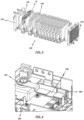
- FIG. 3 shows a cell pack 100 with a plurality of electrochemical cell assemblies 10 for use in the energy storage module 400 according to the invention.
- the electrochemical cell assemblies 10 are arranged in such a way that the first flat connecting lugs 12i and the second flat connecting lugs 12ii of the lithium ion pouch cells 11 are separated from two opposite sides of the cell pack 100 extend. In particular, the two sides are the left and right sides of the cell pack 100.
- Rods 140 are provided on an upper and a lower side, which are received or passed through holes in the cell carriers 15 of the plurality of electrochemical cell assemblies 10.
- End plates 130 are provided on a front and a rear side of the cell pack 100, which form a termination of the cell pack 100.
- the end plates 130 have associated bores through which the rods 140 can be received or passed through.
- Foam plates 150 are arranged between the end plates 130 and a first or last one of the plurality of electrochemical cell assemblies 10 according to the invention.
- the end plates 130 each have a recess, the shape and size of which is designed to accommodate the foam plate 150 at least in some areas.
- an adhesive device such as adhesive strips.
- the cell pack 100 can be assembled by applying a force to the outwardly facing end faces of the two end plates 130.
- the force to be applied is preferably between 100 Newton (N) and 400 Newton (N), but can also be selected differently from these values depending on the design of the cell package. In this way, a necessary minimum compression of the cell pack 100 can be ensured, which, for example, ensures that heat is dissipated from the cell pack 100 or that the cell pack 100 is sufficiently rigid.
- FIG. 4 shows electrical elements of the energy storage module 400 according to the invention, such as an energy storage control device 300, at least two flexible busbar connectors 310 and 320, and a shunt 330.
- the energy storage control device 300 is used to control the operation of the energy storage module 400 and has a circuit board.
- the at least two flexible busbar connectors 310 and 320 have a first flexible busbar connector 310, which is electrically conductively connected to a connection terminal of the energy storage module 400, and a second flexible busbar connector 320, which is electrically conductively connected to the cell pack 100.
- the shunt 330 further includes a first and a second surface, wherein the first or a second surface is connected to the circuit board of the energy storage controller 300 and the second or first surface is connected to the first and second flexible busbar connectors 310 and 320. This allows one very space-saving and easy-to-manufacture electrically conductive connection between the cell pack 100, the energy storage control device 300 and a connection terminal of the energy storage module 400 can be realized.
- connection of the shunt 330 to the first and second flexible busbar connectors 310 and 320, as well as the connection of the shunt 330 to the Circuit board of the energy storage control device 300 is realized via a welded connection.
- a laser beam welding process and/or an ultrasonic welding process is advantageously used for this.
- the connection of the shunt 330 to the flexible busbar connectors 310 and 320 and the circuit board of the energy storage control device 300 can take place in certain areas or over the entire area.
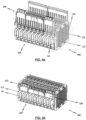
- FIG. 5a shows an exploded view of a contacting device 200 according to the invention.
- the contacting device 200 has a carrier 210 and four busbars 220, 220 ', 220" and 220".
- busbars 220 Of course, in this context it is conceivable that a different number of busbars 220 is provided.
- the carrier 210 has a plurality of tines 211 which have chamfered end regions 212. It can also be seen that the carrier 210 has centering devices in the form of knobs or pins, which can be accommodated at least in associated bores in the two middle busbars 220' 220".
- the carrier 210 has three areas, which are separated by webs, and thus provides three areas for fixedly receiving the bus bars 220, 220 ', 220 "and 220".
- a front bus bar 220 is accommodated in a front area
- the two middle ones Busbars 220' and 220" are accommodated in a middle area
- a rear busbar 220" is accommodated in a rear area.
- Relative information such as "front” and “rear”, also refers here to an installed state of the cell pack or the energy module.
- the front area and the rear area of the carrier 210 have areas in order to be able to accommodate a connection area 223 of the front and rear busbars 220 and 220′′′.
- each of the areas of the carrier 210 can have an adhesive strip 240 in order to connect the bus bars 220, 220 ', 220 "and 220" to the carrier 210, that is, to be able to attach them to it.
- Busbars 220 shown each have a plurality of prongs 221.
- the busbars 220 are made of different materials.
- the front busbar 220 is made of aluminum
- the adjacent middle busbar 220' is made of copper
- the other middle busbar 220" is made of aluminum
- the rear busbar 220" is made of copper.
- a bimetal plate 250 is preferably provided.
- the two materials aluminum and copper can only be welded directly with great effort, which is why the bimetal plate 250 is used, which has a first side made of aluminum and a second side made of copper.
- the side of the bimetallic plate 250 made of aluminum is welded to the busbar 220".
- the side of the bimetal plate 250, which is made of copper is welded to the bus bar 220 '.
- Threaded plates 230 are provided between the busbars 220 and the carrier 210.
- the area of the carrier 210 which receives the connection areas 223 of the busbars 220 and 220′′′, is also designed to be able to accommodate the threaded plate 230.
- FIG. 5b shows the contacting device 200 according to FIG. 3a in an assembled state.
- the busbars 220, 220', 220", 220" are accommodated in the carrier 210.
- the prongs 211 of the carrier 210 are longer than the prongs 221 of the busbars 220, 220', 220" and 220"'. This offers the advantage that only the prongs 211 of the carrier 210 have to have chamfered end regions 212. Accordingly, the busbars 220, 220', 220" and 220' or their prongs 221 are easier to manufacture.
- the webs of the carrier 210 between the front and middle and between the middle and rear areas also serve to electrically isolate the busbars 220 and 220' or the busbars 220" and 220" from one another.
- FIGS. 6a, 6b and 6c show the energy storage module 10 in different manufacturing steps (states).
- FIG. 6a This is how it shows FIG. 6a the cell pack 100 and two contacting devices 200 before pushing on the contacting devices 200.
- FIG. 6b shows the cell pack 100 and the contacting devices 200 in a pushed-on or plugged-in state. It can be seen that the two contacting devices 200 are not or do not have to be designed identically. In particular, it can be seen that only one of the contacting devices 200 has the connection areas 223 of the busbar 220 and 220′′′. Accordingly, the carrier 210 is designed either with or without areas for receiving the connection areas 223.
- the first and second flat connecting lugs 12i and 12ii of the lithium ion pouch cells 11 also have a protective film 113, which is in an intermediate step between FIG. 6b and FIG. 6c Will get removed.
- the protective film 113 serves in particular to protect the surface of the connecting lugs 12i and 12ii.
- connection lugs 12i and 12ii of the lithium ion pouch cells 11 being bent in such a way that they enable electrical contact between the busbars 220, 220 ', 220 "and 220' and the electrochemical cell assemblies 10 .
- contact surfaces between the connecting lugs 12i and 12ii and the busbars 220, 220 ', 220 "and 220" are relatively large due to the flat design of the connecting lugs 12i, 12ii.
- the cell pack 100 and there in particular the end plates 130 also have, as in the FIG. 6a to FIG. 6c can be seen, centering devices. These can be seen in particular on the end plates 130 in the form of projections extending to the sides.
- the contacting devices 200 in particular the carrier 210, also have centering devices, which in FIG. 6a are shown, for example, in the form of struts extending parallel to the tines of the carrier.
- the carrier 210 in an upper area there is a kind of rail, which can be fastened in the upper areas of the cell carriers 15 of the multitude of electrochemical cell assemblies 10 according to the invention. This is in particular a locking device.
- the carrier 210 can be accommodated in a lower region of the cell carrier 15 of the multitude of electrochemical cell assemblies 10 according to the invention.
- This lower area can at the same time form a stop so that the contacting devices 200 can only be pushed onto the connecting lugs 12i and 12ii up to a certain position.
- the large number of electrochemical cell assemblies 10 according to the invention are provided.
- the large number of electrochemical cell assemblies 10 according to the invention are then arranged in stacks to form a cell pack 100.
- the cell pack is designed according to the structure FIG. 3 educated.
- the first and second connection lugs 12i and 12ii are arranged on opposite first and second sides of the cell pack 100.
- the at least one contacting device 200 is pushed onto the flat connecting lugs 12i and 12ii.
- the connection lugs 12i and 12ii are then bent over in such a way that the plurality of electrochemical cell assemblies 10 according to the invention can be or are electrically connected to the at least one contacting device 200.
- the connecting lugs 12i and 12ii are then welded to the at least one contacting device 200 using a multi-part welding tool 500.
- FIG. 7 shows the multi-part welding tool 500 used for assembling the energy storage module 400 according to the invention.
- the multi-part welding tool 500 consists of three main elements, a receiving device 510, an insulating plate 520, and a pressure plate 530.
- the recording device 510 has a base plate 512 with a first surface and a second surface, with position elements 513 being arranged on one of the first or second surfaces.
- the position elements 513 preferably have a substantially cuboid shape, but can also have other geometric shapes.
- the position elements 513 are further arranged at a distance from one another on the base plate 512 of the receiving device 510, so that a space is formed which enables the cell pack 100 to be received in a lateral position.
- a lateral position is a position in which the opposing first and second sides of the cell pack 100, which have the first and second connecting lugs 12i and 12ii, are arranged in a horizontal plane.
- the position elements 513 and the base plate 512 can have first recesses 514 into which fastening elements, such as screws, can be received.
- the positioning elements 513 on the base plate 512 can be aligned according to the structure of the cell pack 100.
- the position elements 513 can have second recesses 515 for receiving fastening elements 540, such as screws, which are required to clamp the cell pack 100 in the multi-part welding tool 500.
- the insulating plate 520 is positioned on the side of the cell pack 100 which is opposite the side of the cell pack 100 received by the cavity.
- the insulating plate 520 is arranged at least partially or completely on the side of the cell pack 100 which is opposite the side of the cell pack 100 received by the cavity.
- the insulating plate 520 also has recesses 521, which are aligned with the areas to be connected of the first and second flat connecting lugs 12i and 12ii and the at least one contacting device 200. This ensures that the welding process only causes the electrical damage conductive connection relevant areas of the connecting lugs 12i and 12ii and the contacting device 200 are connected to one another. In addition, areas and/or elements of the cell pack 100 or the energy storage module 400 are protected from undesirable influences that occur during the welding process.
- the insulating plate 520 can preferably be made of a plastic, such as acrylonitrile-butadiene-styrene, but other materials can also be used.
- the pressure plate 530 is placed on the insulating plate 520.
- the pressure plate also has recesses 531, which are arranged and aligned with the recesses 521 of the insulating plate 520. This ensures accessibility to the areas of the cell pack 100 to be welded.
- the pressure plate 530 also has bulges 532 on its lateral edge regions, which are provided with recesses 533.
- the recesses 533 of the bulges 532 are aligned vertically spaced with the recesses 515 of the positioning elements 513, so that the cell pack 100 is connected to the multi-part via fastening elements 540, which are accommodated in the recesses 515 and 533 of the positioning elements 513 and the bulges 532 of the pressure plate 530 Welding tool 500 is clamped.
- Positioning and bracing of the cell pack 100 in the multi-part welding tool 500 that counteracts unwanted movements can thus be achieved in a simple manner.
- only the required areas of the cell pack 100 or the energy storage module 400 are influenced by the welding process.
- the pressure plate 530 may preferably be made of a metal or a metal alloy, such as aluminum or an aluminum alloy, but manufacturing the pressure plate 530 from other materials is also possible.
- a laser beam welding process is preferably used to weld the first and second connecting lugs 12i and 12ii to the at least one contacting device 200 chosen, which advantageously supports compliance with the high requirements for the manufacturing process of the energy storage module 400 through suitable welding parameters.
Description
Die vorliegende Erfindung betrifft ein Energiespeichermodul gemäß Anspruch 1. Die Erfindung betrifft außerdem ein Verfahren zum Zusammenbau eines Energiespeichermoduls gemäß Anspruch 10.The present invention relates to an energy storage module according to
Derartige Energiespeichermodule werden in vielen Bereichen der Technik eingesetzt. Die vorliegende Erfindung betrifft insbesondere den Bereich der Energiespeichermodule für Fahrzeuge, wobei es sich bei einem Fahrzeug um ein Luft- oder Wasserfahrzeug, ein spurgeführtes Fahrzeug, ein Geländefahrzeug, oder bevorzugt um ein Straßenfahrzeug handeln kann. Als Straßenfahrzeuge werden insbesondere Personenkraftwagen, Lastkraftwagen, Busse oder Wohnmobile verstanden. In Fahrzeugen werden unterschiedliche Arten von Batteriemodulen verbaut, darunter Traktionsbatterien (insbesondere bei Elektrofahrzeugen) und Starterbatterien (Autobatterien). Genauer gesagt soll mindestens eine elektrochemische Zellbaugruppe, sowie eine Starterbatterie insbesondere dadurch festgelegt sein, dass sie zumindest einen Anteil der Energie, vorzugsweise die gesamte Energie, bereitstellt, welche zum Starten eines Fahrzeuges und/oder zum Versorgen von fahrzeuginternen Systemen (Beleuchtung, Pumpen, Zündung) notwendig ist. Als Starterbatterien werden üblicherweise Bleiakkumulatoren eingesetzt, welche jedoch insbesondere aufgrund ihrer niedrigen Energiedichten ein hohes Gewicht aufweisen. Lithiumionen-Akkumulatoren hingegen weisen eine hohe Energiedichte auf. Zudem haben Lithiumionen-Akkumulatoren beispielsweise eine höhere Lebensdauer, eine geringere Selbstentladung, eine verbesserte Schnellladefähigkeit sowie geringere Wartungsintervalle als herkömmliche Bleiakkumulatoren.
Insgesamt werden, insbesondere aufgrund der steigenden Anzahl von Energieverbrauchern, immer höhere Anforderungen an die Leistungsfähigkeit, das Gewicht, die Zuverlässigkeit und die Herstellungskosten von Zellbaugruppen und Batteriemodulen in Fahrzeugen gestellt.Overall, particularly due to the increasing number of energy consumers, ever higher demands are placed on the performance, weight, reliability and manufacturing costs of cell assemblies and battery modules in vehicles.
Daher liegt der Erfindung die Aufgabe zugrunde, ein Energiespeichermodul für die Serienfertigung, insbesondere Großserienfertigung, rationeller zu gestalten, insbesondere im Hinblick auf automatisierte Fertigungsprozesse in Anwendungen für die Automobiltechnik. Zudem ist es eine Aufgabe der vorliegenden Erfindung, ein Energiespeichermodul derart zu gestalten, dass es zum einen zweckmäßig in modularen Fertigungsprozessen einsetzbar ist, und zum anderen besonders gut geeignet für eine spätere Verwendung in Fahrzeugen ist. Außerdem soll ein Batteriespeichermodul durch einfaches Hinzufügen oder Weglassen von Zellbaugruppen an verschiedene Energie- bzw. Leistungsanforderungen anpassbar sein. Ferner soll ein verbessertes und prozesssichereres Verfahren zum Zusammenbau für solche Energiespeichermodule angegeben werden.The invention is therefore based on the object of designing an energy storage module for series production, in particular large-scale production, more efficiently, especially with regard to automated production processes in automotive technology applications. In addition, it is an object of the present invention to design an energy storage module in such a way that, on the one hand, it can be used expediently in modular manufacturing processes and, on the other hand, it is particularly well suited for later use in vehicles. In addition, a battery storage module should be adaptable to different energy or performance requirements by simply adding or omitting cell assemblies. Furthermore, an improved and more process-reliable assembly method for such energy storage modules should be specified.
Im Hinblick auf das Energiespeichermodul wird die der Erfindung zugrundeliegende Aufgabe erfindungsgemäß durch die Gegenstände des unabhängigen Patentanspruchs 1 gelöst. Im Hinblick auf das Verfahren zum Herstellen eines solchen Energiespeichermoduls wird die der Erfindung zugrundeliegende Aufgabe erfindungsgemäß durch den Gegenstand des unabhängigen Patentanspruchs 10 gelöst. Vorteilhafte Weiterbildungen sind in den abhängigen Patentansprüchen angegeben.With regard to the energy storage module, the object on which the invention is based is solved according to the invention by the subjects of
Demnach wird eine elektrochemische Zellbaugruppe angegeben, welche mindestens zwei Lithiumionen-Pouchzellen, ein Flächenelement zur Ausrichtung der mindestens zwei Lithiumionen-Pouchzellen und einen Zellträger aufweist. Dabei sind die mindestens zwei Lithiumionen-Pouchzellen in dem Zellträger angeordnet und stehen miteinander in einer elektrischen Verbindung. Die mindestens zwei Lithiumionen-Pouchzellen weisen eine erste und eine zweite Anschlussfahne auf. Dabei ist das Flächenelement, vorzugsweise mittig, in dem Zellträger angeordnet und ferner von den mindestens zwei Lithiumionen-Pouchzellen sandwichartig umgeben und steht zumindest bereichsweise mit diesen in Kontakt.Accordingly, an electrochemical cell assembly is specified which has at least two lithium-ion pouch cells, a surface element for aligning the at least two lithium-ion pouch cells and a cell carrier. The at least two lithium ion pouch cells are arranged in the cell carrier and are electrically connected to one another. The at least two lithium ion pouch cells have a first and a second connection lug. The surface element is, preferably in the middle, in the cell carrier arranged and further sandwiched by the at least two lithium ion pouch cells and is at least partially in contact with them.
Der Begriff "elektrochemische Zellbaugruppe" und die Kurzform "Zellbaugruppe" wird synonym verwendet. Ferner wird der Begriff "Lithiumionen-Pouchzelle" und die Kurzform "Pouchzelle" ebenfalls synonym verwendet.The term “electrochemical cell assembly” and the short form “cell assembly” are used synonymously. Furthermore, the term “lithium ion pouch cell” and the short form “pouch cell” are also used synonymously.
Durch den Vorschlag, die elektrochemische Zellbaugruppe derart auszubilden, dass die mindestens zwei Lithiumionen-Pouchzellen in dem Zellträger angeordnet werden und ein Flächenelement, welches mittig in dem Zellträger angeordnet ist, sandwichartig umgeben, wird eine äußerst kompakte Bauweise der Zellbaugruppe erreicht, welche einfach und durch wenige Standardbauteile realisierbar ist. Zudem ist durch die sandwichartige Anordnung der Lithiumionen-Pouchzellen um das mittig im Zellträger positionierte Flächenelement eine sichere planare Anordnung der Elemente im Zellträger gewährleistet, sodass Fertigungstoleranzen an die Zellbaugruppe sicher einzuhalten sind. Planar bedeutet in diesem Kontext, dass die Elemente, insbesondere aneinander angrenzende Elemente, flächig bzw. eben zueinander ausgerichtet sind.The proposal to design the electrochemical cell assembly in such a way that the at least two lithium ion pouch cells are arranged in the cell carrier and sandwich-like a surface element which is arranged centrally in the cell carrier, an extremely compact design of the cell assembly is achieved, which is simple and through few standard components can be implemented. In addition, the sandwich-like arrangement of the lithium ion pouch cells around the surface element positioned in the middle of the cell carrier ensures a secure planar arrangement of the elements in the cell carrier, so that manufacturing tolerances for the cell assembly can be reliably maintained. In this context, planar means that the elements, especially adjacent elements, are flat or aligned with one another.
Gemäß einem weiteren Aspekt sind die ersten und zweiten Anschlussfahnen der mindestens zwei Lithiumionen-Pouchzellen flächig ausgebildet und erstrecken sich zumindest im Wesentlichen senkrecht von zwei gegenüberliegenden Seiten der mindestens zwei Lithiumionen-Pouchzellen aus. Hierdurch wird die kompakte Bauweise der Zellbaugruppen zusätzlich unterstützt und eine äußerst vorteilhafte Kontaktierungsmöglichkeit angegeben.According to a further aspect, the first and second connection lugs of the at least two lithium ion pouch cells are flat and extend at least substantially vertically from two opposite sides of the at least two lithium ion pouch cells. This additionally supports the compact design of the cell assemblies and provides an extremely advantageous contacting option.
Im Wesentlichen senkrecht von einer Seite des Zellenpakets bedeutet in diesem Zusammenhang, dass der Winkel zwischen der Seite des Zellenpakets und der jeweiligen Anschlussfahne innerhalb eines Bereich von 70 Grad bis 110 Grad, vorzugsweise innerhalb eines Bereichs von 80 Grad bis 100 Grad, und besonders bevorzugt innerhalb eines Bereichs von 85 Grad bis 95 Grad liegt. Insbesondere ist es selbstverständlich in diesem Zusammenhang äußerst bevorzugt, wenn der Winkel 90° beträgt.Substantially perpendicular from one side of the cell pack means in this context that the angle between the side of the cell pack and the respective connection lug is within a range of 70 degrees to 110 degrees, preferably within a range of 80 degrees to 100 degrees, and particularly preferably within a range of 85 degrees to 95 degrees. In particular, it is of course extremely preferred in this context if the angle is 90°.
Gemäß einem weiteren Aspekt sind die erste und zweite Anschlussfahne der mindestens zwei Lithiumionen-Pouchzellen biegbar. Hierdurch lässt sich in einem späteren Arbeitsschritt eine besonders einfache und schnelle Möglichkeit der elektrischen Verbindung von Zellbaugruppen untereinander realisieren. Ferner bietet dies insbesondere den weiteren Vorteil, dass eine verhältnismäßig große Kontaktfläche bereitgestellt wird, sodass ein sicheres und großflächiges Kontaktieren ermöglicht.According to a further aspect, the first and second connection lugs of the at least two lithium ion pouch cells are bendable. This allows In a later step, a particularly simple and quick way to electrically connect cell assemblies to one another can be implemented. Furthermore, this offers the further advantage in particular that a relatively large contact area is provided, so that safe and large-area contacting is possible.
Gemäß einem weiteren Aspekt sind die mindestens zwei Lithiumionen-Pouchzellen in Reihe oder parallel schaltbar, sodass sich im Hinblick auf eine spätere Verwendung der Zellbaugruppen in einem Energiespeichermodul der Vorteil einer flexiblen Anpassung der Zellbaugruppen an Anwendungsrandbedingungen des Energiespeichermoduls ergibt.According to a further aspect, the at least two lithium ion pouch cells can be connected in series or in parallel, so that with regard to later use of the cell assemblies in an energy storage module, there is the advantage of flexible adaptation of the cell assemblies to the application conditions of the energy storage module.
Gemäß einem weiteren Aspekt steht das Flächenelement zumindest bereichsweise über eine Klebschicht mit den mindestens zwei Lithiumionen-Pouchzellen in Verbindung. Unter Berücksichtigung der sandwichartigen Anordnung der Litihiumionen-Pouchzellen um das Flächenelement im Zellträger, wird durch die bereichsweise Verklebung die planare Ausrichtung der Elemente in der Zellbaugruppe und die Einhaltung von Fertigungstoleranzen zusätzlich verbessert. Zur Verklebung des Flächenelements mit den mindestens zwei Lithiumionen-Pouchzellen wird gemäß einem weiteren Aspekt der Erfindung ein Acrylklebstoff, ein Epoxidklebstoff und/oder ein doppelseitiges Klebeband genutzt. Ein Einsatz weitere Klebstoffe, welche die Anforderungen an die Verklebung erfüllen, ist jedoch nicht ausgeschlossen.According to a further aspect, the surface element is connected to the at least two lithium ion pouch cells at least in some areas via an adhesive layer. Taking into account the sandwich-like arrangement of the lithium ion pouch cells around the surface element in the cell carrier, the area-by-area bonding further improves the planar alignment of the elements in the cell assembly and compliance with manufacturing tolerances. According to a further aspect of the invention, an acrylic adhesive, an epoxy adhesive and/or a double-sided adhesive tape is used to bond the surface element to the at least two lithium ion pouch cells. However, the use of other adhesives that meet the bonding requirements is not ruled out.
Gemäß einem weiteren Aspekt weist das Flächenelement einen Temperatursensor auf. Hierdurch ist es möglich, den Temperaturverlauf der Zellbaugruppen im Betrieb zuverlässig zu überprüfen, sodass bei Unregelmäßigkeiten und/oder Anomalien im Temperaturverlauf Maßnahmen getroffen werden können.According to a further aspect, the surface element has a temperature sensor. This makes it possible to reliably check the temperature profile of the cell assemblies during operation, so that measures can be taken in the event of irregularities and/or anomalies in the temperature profile.
Gemäß einem weiteren Aspekt ist das Flächenelement aus einem Metall oder einer Metalllegierung gefertigt. Die Verwendung eines Metalls oder einer Metalllegierung zur Ausbildung des Flächenelements sorgt vorteilhaft dafür, dass die planare Anordnung der Elemente in der Zellbaugruppe auch bei Schwankungen der Temperatur gewährleistet werden kann. Zusätzlich kann eine Wärmeleitung über das Flächenelement erzielen werden, sodass das Flächenelement als Wärmeleitelement fungiert.According to a further aspect, the surface element is made of a metal or a metal alloy. The use of a metal or a metal alloy to form the surface element advantageously ensures that the planar arrangement of the elements in the cell assembly can be guaranteed even in the event of temperature fluctuations. In addition, heat conduction can be used can be achieved via the surface element, so that the surface element acts as a heat-conducting element.
Die eingangs genannte Aufgabe wird gemäß dem unabhängigen Patentanspruch 1 durch ein Energiespeichermodul gelöst, welches eine Vielzahl der elektrochemischen Zellbaugruppen, eine Energiespeicher-Steuereinrichtung zur Steuerung des Betriebs des Energiespeichers, mindestens zwei flexible Sammelschienenverbinder, einen Shunt und mindestens eine Kontaktierungsvorrichtung zum elektrischen Kontaktieren der Vielzahl von elektrochemischen Zellbaugruppen aufweist. Dabei weist die Energiespeicher-Steuerungseinrichtung eine Leiterplatte auf. Die Vielzahl von elektrochemischen Zellbaugruppen ist stapelförmig angeordnet, derart, dass sie ein Zellenpaket ausbildet. Ferner steht die Vielzahl von elektrochemischen Zellbaugruppen zumindest teilweise untereinander elektrisch in Verbindung. Der Shunt weist eine erste Oberfläche und eine zweite Oberfläche auf, wobei die erste Oberfläche des Shunts zumindest bereichsweise mit den mindestens zwei flexiblen Sammelschienenverbindern und die zweite Oberfläche zumindest bereichsweise mit der Leiterplatte der Energiespeicher-Steuerungseinrichtung in Kontakt steht.The task mentioned at the outset is achieved according to
Vorzugsweise handelt es sich bei dem Energiespeichermodul um eine Starterbatterie für ein Fahrzeug, wobei die elektrochemischen Zellbaugruppen Lithiumionen-Pouchzellen aufweisen, wodurch die eingangs genannten Vorteile von Lithiumionen-Akkumulatoren im Vergleich zu Bleiakkumulatoren realisiert werden. Durch den erfindungsgemäßen Vorschlag, die Vielzahl von elektrochemischen Zellbaugruppen stapelförmig anzuordnen, derart, dass sie ein Zellenpaket ausbildet, wird ein äußerst kompakter Aufbau des Energiespeichermoduls ermöglicht. Darüber hinaus wird die Anzahl von gleichartigen Komponenten erhöht, welche die Produktionskosten des Energiespeichermoduls deutlich senkt. Ferner werden diese Vorteile durch den Shunt unterstützt, welcher eine erste Oberfläche und eine zweite Oberfläche aufweist, wobei die erste Oberfläche des Shunts zumindest bereichsweise mit den mindestens zwei flexiblen Sammelschienenverbindern und die zweite Oberfläche zumindest bereichsweise mit der Leiterplatte der Energiespeicher-Steuerungseinrichtung in Kontakt steht. Eine Kontaktierung des Shunts an zwei Oberflächen erlaubt eine Anordnung des Shunts zwischen der Energiespeicher-Steuerungseinrichtung und den mindestens zwei Sammelschienenverbindern, derart, dass der Shunt unmittelbar mit diesen Elementen des Energiespeichermoduls in Kontakt steht. Hierdurch wird eine komplizierte Verbindung des Shunts mit den Elementen über Adapter und/oder Steckkontakte, welche viel Bauraum benötigen, verhindert.The energy storage module is preferably a starter battery for a vehicle, with the electrochemical cell assemblies having lithium-ion pouch cells, whereby the advantages of lithium-ion accumulators mentioned above are realized in comparison to lead accumulators. The proposal according to the invention to arrange the large number of electrochemical cell assemblies in a stack in such a way that they form a cell pack makes an extremely compact structure of the energy storage module possible. In addition, the number of similar components is increased, which significantly reduces the production costs of the energy storage module. Furthermore, these advantages are supported by the shunt, which has a first surface and a second surface, the first surface of the shunt being in contact at least in some areas with the at least two flexible busbar connectors and the second surface being in contact at least in some areas with the circuit board of the energy storage control device. Contacting the shunt on two surfaces allows the shunt to be arranged between the energy storage control device and the at least two busbar connectors, such that the shunt is in direct contact with these elements of the energy storage module. This prevents a complicated connection of the shunt to the elements via adapters and/or plug contacts, which require a lot of installation space.
Gemäß einem weiteren Aspekt der Erfindung sind die erste und zweite Oberfläche des Shunts mittels einer Schweißnaht, vorzugsweise mittels einer Laserstrahlschweißnaht und/oder einer Ultraschallschweißnaht, mit den mindestens zwei flexiblen Sammelschienenverbindern und der Leiterplatte der Energiespeicher-Steuerungseinrichtung verbunden. Hierdurch wird eine gezielte, örtlich festgelegte Verbindung äußerst hoher Qualität der Elemente miteinander erzielt, ohne zusätzliches Material oder Bauteile zu verwenden, welche zusätzliches Gewicht in das Energiespeichermodul einbringen würden, sowie zusätzlichen Bauraum benötigen würden. Ein weiterer Vorteil einer Verbindung mittels einer Schweißnaht, vorzugsweise einer Laserschweißnaht und/oder einer Ultraschallschweißnaht, ist die Steigerung der Automatisierung bei der Herstellung des Energiespeichermoduls.According to a further aspect of the invention, the first and second surfaces of the shunt are connected to the at least two flexible busbar connectors and the circuit board of the energy storage control device by means of a weld, preferably by means of a laser beam weld and/or an ultrasonic weld. This achieves a targeted, locally fixed connection of extremely high quality between the elements without using additional material or components, which would introduce additional weight into the energy storage module and require additional installation space. Another advantage of a connection using a weld seam, preferably a laser weld seam and/or an ultrasonic weld seam, is the increase in automation in the production of the energy storage module.
Gemäß einem weiteren Aspekt der Erfindung ist ein erster flexibler Sammelschienenverbinder der mindestens zwei flexiblen Sammelschienenverbinder mit einer Anschlussklemme des Energiespeichermoduls elektrisch verbunden und ein zweiter flexibler Sammelschienenverbinder der mindestens zwei flexiblen Sammelschienenverbinder mit dem Zellenpaket verbunden.According to a further aspect of the invention, a first flexible busbar connector of the at least two flexible busbar connectors is electrically connected to a connection terminal of the energy storage module and a second flexible busbar connector of the at least two flexible busbar connectors is connected to the cell pack.
Gemäß einer vorteilhaften Weiterbildung der Erfindung ist die mindestens eine Kontaktierungsvorrichtung im Wesentlichen kammförmig ausgebildet und weist eine Vielzahl von Zinken auf. Ferner ist jede der ersten und zweiten Anschlussfahnen jeweils zwischen zwei benachbarten Zinken der mindestens einen Kontaktierungsvorrichtung aufgenommen.According to an advantageous development of the invention, the at least one contacting device is essentially comb-shaped and has a plurality of prongs. Furthermore, each of the first and second connecting lugs is received between two adjacent prongs of the at least one contacting device.
Somit ist es möglich, jede einzelne der Anschlussfahnen mit der Kontaktierungsvorrichtung in einem späteren Arbeitsschritt elektrisch zu verbinden. Der erfindungsgemäße Vorschlag stellt somit einen besonders schnellen und rationellen Zusammenbau eines Energiespeichermoduls zur Verfügung, insbesondere dadurch, dass die kammförmige Kontaktierungsvorrichtung auf die Anschlussfahnen der elektrochemischen Zellen aufgeschoben werden können. Es ist daher mit wenigen Handgriffen möglich, das Energiespeichermodul zusammenzubauen bzw. für einen nachfolgenden Montageschritt bereitzustellen.It is therefore possible to electrically connect each of the connecting lugs to the contacting device in a later step. The proposal according to the invention thus provides a particularly quick and efficient assembly of an energy storage module, in particular in that the comb-shaped contacting device can be pushed onto the connecting lugs of the electrochemical cells. It is therefore with It is possible to assemble the energy storage module in just a few steps or to prepare it for a subsequent assembly step.
Des Weiteren wirken die Zinken mit den Anschlussfahnen als eine Art Zentrierungsvorrichtung zusammen und erleichtern somit weiter den Zusammenbau. Selbstverständlich ist es in diesem Zusammenhang denkbar, dass weitere Zentrierungsvorrichtungen, insbesondere an der Kontaktierungsvorrichtung, vorgesehen sind.Furthermore, the prongs work together with the connecting lugs as a kind of centering device and thus further facilitate assembly. Of course, in this context it is conceivable that further centering devices, in particular on the contacting device, are provided.
Weitere Vorteile werden auch dadurch erlangt, dass bei einer Verwendung von Lithiumionen-Pouchzellen diese direkt zu einem Zellenpaket ausgebildet werden können. Das heißt, dass es beispielweise nicht mehr nötig ist, mehrere Lithiumionen-Pouchzellen durch einen vorherigen Montageschritt zu verbinden. Insbesondere wird dadurch auch die Anwendung des Energiespeichermoduls insgesamt universeller, da die einzelnen Zellen bzw. ihre Anschlussfahnen unterschiedlich zueinander ausgerichtet werden können. Somit muss also nicht vorab festgelegt werden, ob eine Reihen- oder Parallelschaltung einzelner Zellen erreicht werden soll.Further advantages are also achieved in that when lithium ion pouch cells are used, they can be formed directly into a cell pack. This means that, for example, it is no longer necessary to connect several lithium-ion pouch cells through a previous assembly step. In particular, this also makes the application of the energy storage module more universal overall, since the individual cells or their connecting lugs can be aligned differently to one another. This means that it is not necessary to determine in advance whether individual cells should be connected in series or in parallel.
Insgesamt sinken sowohl die Kosten als auch die Durchlaufzeit der Fertigung deutlich. Unter Durchlaufzeit wird in diesem Zusammenhang die Zeitspanne verstanden, welche bei der Fertigung eines Produktes zwischen dem Beginn des ersten Arbeitsvorganges und dem Abschluss des letzten Arbeitsvorganges verstreicht.Overall, both the costs and the lead time of production decrease significantly. In this context, lead time is understood to be the period of time that elapses in the production of a product between the start of the first work process and the completion of the last work process.
Gemäß einer vorteilhaften Weiterbildung der Erfindung weist die mindestens eine Kontaktierungsvorrichtung mindestens eine Sammelschiene und mindestens einen Träger auf, wobei die mindestens eine Sammelschiene und der mindestens eine Träger kammförmig ausgebildet sind und die Vielzahl von Zinken aufweisen.According to an advantageous development of the invention, the at least one contacting device has at least one busbar and at least one carrier, wherein the at least one busbar and the at least one carrier are comb-shaped and have the plurality of prongs.
Somit ist die Kontaktierungsvorrichtung ebenfalls modular aufgebaut, wodurch sich die Modularität des Gesamtsystems weiter erhöht, da unterschiedliche Sammelschienen eingebaut werden können. Es entstehen somit mehr Möglichkeiten zum Zusammenbau (Variantenanzahl steigt) und gleichzeitig weniger Einschränkung (Vorabfestlegungen).The contacting device therefore also has a modular structure, which further increases the modularity of the overall system since different busbars can be installed. This creates more options for assembly (the number of variants increases) and at the same time fewer restrictions (preliminary specifications).
Des Weiteren erhöht sich die Stabilität der Kontaktierungsvorrichtung durch den mindestens einen Träger, welcher auch weitere Zentrierungs- oder Einbauhilfen aufweisen kann.Furthermore, the stability of the contacting device is increased by the at least one carrier, which can also have further centering or installation aids.
Durch den erfindungsgemäßen Vorschlag, die Kontaktierungsvorrichtung aus mindestens einer Sammelschiene und mindestens einem Träger aufzubauen, wird zudem eine Trennung der Funktionen angestrebt. Diesbezüglich erfüllt die mindestens eine Sammelschiene die Funktion einer elektrischen Kontaktierung und der mindestens eine Träger die Funktion einer Halterung bzw. einer Befestigung und/oder einer Zentrierung bzw. einer Positionierung.The proposal according to the invention to construct the contacting device from at least one busbar and at least one carrier also aims to separate the functions. In this regard, the at least one busbar fulfills the function of electrical contacting and the at least one carrier fulfills the function of a holder or a fastening and/or a centering or a positioning.
Dadurch ist es insbesondere möglich, die Kontaktierungsvorrichtung derart auszubilden oder zu gestalten, dass lediglich die mindestens eine Sammelschiene aus elektrisch leitfähigem Material ausgebildet ist, wohingegen die Kontaktierungsvorrichtung aus einem elektrisch nicht leitfähigen Material ausgebildet werden kann. Es ist somit möglich, stromführende Bereiche von Bereichen, welche keinen Strom führen, zu trennen. Als Material für den mindestens einen Träger kommt dabei beispielsweise ein Acrylnitril-Butadien-Styrol, Polycarbonat, Polyamid, Polyvinylchlorid, Polyethylenterephthalat, Polyoxymethylen oder ein Copolymer hiervon in Frage.This makes it possible in particular to design or design the contacting device in such a way that only the at least one busbar is made of electrically conductive material, whereas the contacting device can be made of an electrically non-conductive material. It is therefore possible to separate current-carrying areas from areas that do not carry electricity. Possible materials for the at least one carrier are, for example, acrylonitrile-butadiene-styrene, polycarbonate, polyamide, polyvinyl chloride, polyethylene terephthalate, polyoxymethylene or a copolymer thereof.
Gemäß einer vorteilhaften Weiterbildung der Erfindung ist die mindestens eine Sammelschiene in dem mindestens einen Träger aufnehmbar bzw. aufgenommen und/oder an ihm befestigbar bzw. befestigt.According to an advantageous development of the invention, the at least one busbar can be accommodated or accommodated in the at least one carrier and/or can be fastened or fastened to it.
Somit wird der Zusammenbau weiter vereinfacht, insbesondere, wenn der mindestens eine Träger festgelegte Bereiche aufweist, in welche die mindestens eine Sammelschiene aufnehmbar ist. Derartige Bereiche können beispielsweise durch eine Außenkontur des Trägers und/oder durch Stege realisiert sein. Insbesondere wird somit auch sichergestellt, dass die Sammelschiene in einer bestimmten und vorgesehenen Art und Weise mit dem mindestens einen Träger verbunden wird. Zur Befestigung eignen sich beispielsweise Fügemittel, insbesondere Klebstoffe, vorzugsweise solche in Form von Klebestreifen.The assembly is thus further simplified, particularly if the at least one carrier has defined areas into which the at least one busbar can be received. Such areas can be realized, for example, by an outer contour of the carrier and/or by webs. In particular, this also ensures that the busbar is connected to the at least one carrier in a specific and intended manner. For example, joining agents, in particular adhesives, preferably those in the form of adhesive strips, are suitable for fastening.
Gemäß einem weiteren Aspekt der Erfindung weist das Zellenpaket zwei Endplatten auf, welche an beiden Enden der stapelförmig angeordneten Vielzahl von elektrochemischen Zellbaugruppen vorgesehen sind. Hierdurch wird ein vorderes, bzw. hinteres Ende des Zellenpakets ausgebildet, welches das Zellenpaket vor äußeren auf die Stirnflächen des Zellenpakets wirkende Belastungen schützt.According to a further aspect of the invention, the cell pack has two end plates, which are arranged at both ends of the stacked plurality of electrochemical cell assemblies are provided. This creates a front or rear end of the cell pack, which protects the cell pack from external loads acting on the end faces of the cell pack.
Vorzugsweise sind die Endplatten aus Kunststoff, insbesondere aus Acrylnitril-Butadien-Styrol, Polycarbonat, Polyamid, Polyvinylchlorid, Polyethylenterephthalat, Polyoxymethylen oder ein Copolymer hiervon hergestellt.The end plates are preferably made of plastic, in particular acrylonitrile-butadiene-styrene, polycarbonate, polyamide, polyvinyl chloride, polyethylene terephthalate, polyoxymethylene or a copolymer thereof.
Gemäß einer vorteilhaften Weiterbildung der Erfindung weisen die Endplatten Bohrungen auf, welche fluchtend mit Bohrungen der Vielzahl von elektrochemischen Zellbaugruppen angeordnet und ausgerichtet sind, wobei das Zellenpaket ferner eine Vielzahl von Stäben aufweist, welche durch die Bohrungen der Vielzahl von elektrochemischen Zellbaugruppen und durch die Bohrungen der Endplatten führbar oder geführt sind, um diese zu verbinden, das heißt die Vielzahl von Stäben wird durch die Bohrungen gesteckt.According to an advantageous development of the invention, the end plates have bores which are arranged and aligned in alignment with bores of the plurality of electrochemical cell assemblies, the cell pack further having a plurality of rods which pass through the bores of the plurality of electrochemical cell assemblies and through the bores of the End plates can be guided or guided in order to connect them, that is, the large number of rods are inserted through the holes.
Insgesamt entsteht somit ein äußerst stabiler und modularer Aufbau des Zellenpakets. Auch hier ist es wiederum möglich, den Zusammenbau des Zellenpakets an einer separaten Arbeitsstation vorzusehen, um den Fertigungsablauf weiter zu optimieren. So kann beispielsweise an einer ersten Arbeitsstation eine Vielzahl der erfindungsgemäßen elektrochemischen Zellbaugruppen gefertigt werden und an einer nachfolgenden zweiten Arbeitsstation können die Vielzahl von elektrochemischen Zellbaugruppen zusammen mit den Endplatten zu einem Zellenpaket verbunden werden, welches anschließend an eine dritte Arbeitsstation weitergegeben werden kann.Overall, this creates an extremely stable and modular structure for the cell pack. Here too, it is again possible to assemble the cell pack at a separate work station in order to further optimize the manufacturing process. For example, a large number of electrochemical cell assemblies according to the invention can be manufactured at a first work station and at a subsequent second work station, the large number of electrochemical cell assemblies can be connected together with the end plates to form a cell pack, which can then be passed on to a third work station.
Vorzugsweise sind in jedem Zellträger und in jeder Endplatte vier Bohrungen vorgesehen bzw. angeordnet, welche besonders bevorzugt an den beiden Seiten des Zellenpakets vorgesehen sind, von welchen sich die Anschlussfahnen der elektrochemischen Zellen nicht aus erstrecken; das heißt an einer Oberseite und einer Unterseite des Zellenpakets sind jeweils zwei Bohrungen vorgesehen bzw. angeordnet.Four bores are preferably provided or arranged in each cell carrier and in each end plate, which are particularly preferably provided on the two sides of the cell pack from which the connecting lugs of the electrochemical cells do not extend; This means that two holes are provided or arranged on a top and a bottom of the cell pack.
Die beschriebene Anordnung des Zellenpakets mit einer Vielzahl von Stäben ist auch deswegen vorteilhaft, da die Stäbe zusammen mit den Bohrungen eine Zentrierungsfunktion erfüllen.The described arrangement of the cell pack with a large number of rods is also advantageous because the rods, together with the bores, fulfill a centering function.
Vorzugsweise weisen die Stäbe an ihren Endbereichen Gewinde auf, um Befestigungsmittel aufschrauben zu können.The rods preferably have threads at their end regions so that fasteners can be screwed on.
Gemäß einer vorteilhaften Weiterbildung der Erfindung ist jeweils eine Schaumplatte zwischen äußeren, also einer vorderen und einer hinteren, Zellbaugruppen der stapelförmig angeordneten Vielzahl von elektrochemischen Zellbaugruppen und den Endplatten vorgesehen.According to an advantageous development of the invention, a foam plate is provided between outer, i.e. a front and a rear, cell assemblies of the stacked plurality of electrochemical cell assemblies and the end plates.
Durch den erfindungsgemäßen Vorschlag kann erreicht werden, dass ein Anpressdruck, welcher durch die Endplatten auf das Zellenpaket, bzw. die elektrochemischen Zellbaugruppen wirkt, gleichmäßig verteilt wird. Zusätzlich besitzen die Schaumplatten eine Dämpfwirkung, wodurch das Zellenpaket und insbesondere die elektrochemischen Zellbaugruppen vor Vibrationen und/oder Stößen geschützt werden können.The proposal according to the invention can ensure that a contact pressure, which acts on the cell package or the electrochemical cell assemblies through the end plates, is evenly distributed. In addition, the foam plates have a damping effect, whereby the cell package and in particular the electrochemical cell assemblies can be protected from vibrations and/or shocks.
Die Befestigung der Schaumplatte erfolgt vorzugsweise über einen Klebstoff, wobei die Schaumplatten besonders bevorzugt an die Endplatten geklebt werden.The foam plate is preferably attached using an adhesive, with the foam plates particularly preferably being glued to the end plates.
Gemäß einer vorteilhaften Weiterbildung der Erfindung weist das Energiespeichermodul ferner ein Modulgehäuse und einen Deckel auf.According to an advantageous development of the invention, the energy storage module further has a module housing and a cover.
Als Befestigungsmittel des Modulgehäuses und des Deckels bieten sich auch hier insbesondere Schrauben, Bolzen oder Nieten an. In diesem Zusammenhang werden vorzugsweise der Deckel und/oder das Modulgehäuse mit den Endplatten des Zellenstapels verbunden, welche zu diesem Zweck Bohrungen bzw. Gewindebohrungen aufweisen.Screws, bolts or rivets are particularly suitable as fastening means for the module housing and the cover. In this context, the cover and/or the module housing are preferably connected to the end plates of the cell stack, which have holes or threaded holes for this purpose.
Am Deckel sind eine Vielzahl von Einrichtungen vorgesehen, beispielsweise Anschlüsse für im Energiespeichermodul benutzte Sensoren, Entlüftungseinrichtungen und Terminals zum Kontaktieren mit einem elektrischen Verbraucher. Die Terminals zum Kontaktieren mit einem elektrischen Verbraucher sind elektrisch mit dem Anschlussbereich bzw. den Anschlussbereichen der mindestens einen Sammelschiene verbunden.A variety of devices are provided on the cover, for example connections for sensors used in the energy storage module, ventilation devices and terminals for contacting an electrical consumer. The terminals for contacting an electrical consumer are electrically connected to the connection area or the connection areas of the at least one busbar.
Die eingangs genannte Aufgabe wird außerdem gemäß Anspruch 10 durch ein
Verfahren zum Zusammenbau eines Energiespeichermoduls gelöst, wobei das Verfahren folgende Schritte aufweist: Bereitstellen einer Vielzahl von elektrochemischen Zellbaugruppen, wobei jede der Vielzahl von elektrochemischen Zellbaugruppen mindestens zwei Lithiumionen-Pouchzellen, einen Zellträger und ein Flächenelement zur Ausrichtung der mindestens zwei Lithiumionen-Pouchzellen aufweist und wobei jede der mindestens zwei Lithiumionen-Pouchzellen eine erste und zweite flächige Anschlussfahne aufweist; stapelförmiges Anordnen einer Vielzahl von elektrochemischen Zellbaugruppen zu einem Zellenpaket, wobei die ersten und zweiten Anschlussfahnen auf sich gegenüberliegenden ersten und zweiten Seiten des Zellenpakets angeordnet sind; Aufschieben von mindestens einer Kontaktierungsvorrichtung auf flächig ausgebildete Anschlussfahnen; Biegen der Anschlussfahnen derart, dass die Vielzahl von elektrochemischen Zellbaugruppen mit der mindestens einen Kontaktierungsvorrichtung elektrisch verbindbar oder verbunden ist; Schweißen der Anschlussfahnen an die mindestens eine Kontaktierungsvorrichtung unter Verwendung eines mehrteiligen Schweißwerkzeugs.The task mentioned at the beginning is also carried out according to
Method for assembling an energy storage module solved, the method has the following steps: providing a plurality of electrochemical cell assemblies, each of the plurality of electrochemical cell assemblies having at least two lithium ion pouch cells, a cell carrier and a surface element for aligning the at least two lithium ion pouch cells and wherein each of the at least two lithium ion pouch cells has a first and has a second flat connecting lug; stacking a plurality of electrochemical cell assemblies to form a cell pack, the first and second connection tabs being arranged on opposite first and second sides of the cell pack; Pushing at least one contacting device onto flat connecting lugs; Bending the connection lugs such that the plurality of electrochemical cell assemblies can be or is electrically connected to the at least one contacting device; Welding the connection lugs to the at least one contacting device using a multi-part welding tool.
Der erfindungsgemäße Vorschlag die Anschlussfahnen an die mindestens eine Kontaktierungsvorrichtung zu schweißen ist insbesondere deswegen vorteilhaft, da durch das Schweißen innerhalb einer kurzen Zeitspanne eine große Kontakt- bzw. Verbindungsfläche zwischen den Anschlussfahnen und der Kontaktierungsvorrichtung geschaffen werden kann. Somit ist das Schweißen aufgrund der kurzen Bearbeitungszeit besonders gut bei automatisierten Fertigungsprozessen einsetzbar und gleichzeitig äußerst zuverlässig. Zudem kann auf weitere verbindende Bauteile, wie beispielsweise auf Schrauben, verzichtet werden und der Aufbau wird weiterhin vereinfacht. Auch ist der elektrische Widerstand bei einer Schweißverbindung deutlich geringer als bei einer Verbindung, welche beispielsweise durch Schrauben bereitgestellt wird.The proposal according to the invention to weld the connecting lugs to the at least one contacting device is particularly advantageous because welding can create a large contact or connection area between the connecting lugs and the contacting device within a short period of time. Due to the short processing time, welding can be used particularly well in automated manufacturing processes and is extremely reliable at the same time. In addition, further connecting components, such as screws, can be dispensed with and the structure is further simplified. The electrical resistance of a welded connection is also significantly lower than that of a connection provided, for example, by screws.
Ferner wird durch die Verwendung eines mehrteiligen Schweißwerkzeugs eine hochpräzise und mechanisch sichere Ausbildung einer elektrisch leitfähigen Verbindung zwischen den flächig ausgebildeten Anschlussfahnen und der Kontaktierungsvorrichtung erzielt. Hierdurch werden der Automatisierungsgrad und die Prozessstabilität bei der Herstellung des Energiespeichermoduls gesteigert.Furthermore, by using a multi-part welding tool, a highly precise and mechanically secure formation of an electrically conductive connection between the flat connecting lugs and the contacting device is achieved. This increases the degree of automation and process stability in the production of the energy storage module.
Gemäß einem weiteren Aspekt der Erfindung weist das (im Verfahren genutzte) mehrteilige Schweißwerkzeug eine Aufnahmevorrichtung, eine Isolierplatte und eine Druckplatte auf. Durch diesen dreiteiligen Aufbau des mehrteiligen Schweißwerkzeuges wird das vorgefertigte Zellenpaket positionssicher während der Durchführung des Schweißvorgangs der Anschlussfahnen an die mindestens eine Kontaktierungsvorrichtung fixiert. Die hochpräzise und mechanisch sichere Ausbildung einer elektrisch leitfähigen Verbindung wird so zusätzlich unterstützt.According to a further aspect of the invention, the multi-part welding tool (used in the method) has a receiving device, an insulating plate and a pressure plate. Thanks to this three-part structure of the multi-part welding tool The prefabricated cell package is fixed in a secure position during the welding process of the connecting lugs to the at least one contacting device. This additionally supports the highly precise and mechanically safe formation of an electrically conductive connection.
Gemäß einem weiteren Aspekt der Erfindung weist die Aufnahmevorrichtung eine Basisplatte mit voneinander beabstandeten Positionselementen auf, wobei die Positionselemente derart auf der Basisplatte angeordnet sind, sodass das Zellenpaket mit der ersten oder zweiten Seite der Basisplatte zugewandt in die Aufnahmevorrichtung aufnehmbar bzw. aufgenommen ist. Durch die Anordnung der Positionselemente auf der Basisplatte der Aufnahmevorrichtung wird die exakte Form (unter Berücksichtigung von Toleranzen) des Zellenpakets in der Aufnahmevorrichtung abgebildet, sodass eine horizontale Bewegung des Zellenpakets während des Schweißvorgangs verhindert wird.According to a further aspect of the invention, the receiving device has a base plate with position elements spaced apart from one another, the position elements being arranged on the base plate in such a way that the cell pack can be received or accommodated in the receiving device with the first or second side facing the base plate. By arranging the position elements on the base plate of the holding device, the exact shape (taking tolerances into account) of the cell pack is reproduced in the holding device, so that horizontal movement of the cell pack is prevented during the welding process.
Die Anordnung des Zellenpakets mit der ersten oder zweiten Seite in der Aufnahmevorrichtung erlaubt zudem, dass eine einfache Zugänglichkeit zu den zu verbindenden Bereichen der ersten und zweiten Anschlussfahnen und der mindestens einen Kontaktierungsvorrichtung durchgehend gewährleistet ist. Die erste und zweite Seite des Zellenpakets beschreiben dabei die sich gegenüberliegenden Seiten des Zellenpakets auf denen die ersten und zweiten Anschlussfahnen und die mindestens eine Kontaktierungsvorrichtung angeordnet sind.The arrangement of the cell pack with the first or second side in the receiving device also allows easy accessibility to the areas to be connected of the first and second connecting lugs and the at least one contacting device to be guaranteed throughout. The first and second sides of the cell pack describe the opposite sides of the cell pack on which the first and second connection lugs and the at least one contacting device are arranged.
Gemäß einem weiteren Aspekt der Erfindung ist die Isolierplatte zumindest bereichsweise auf der zweiten oder ersten Seite des Zellenpakets positioniert, wobei die Isolierplatte Aussparungen aufweist, welche fluchtend mit zu verbindenden Bereichen der Anschlussfahnen und der mindestens einen Kontaktierungsvorrichtung ausgerichtet ist. Durch die Verwendung einer fluchtend ausgerichteten, Aussparungen aufweisenden Isolierplatte auf der zweiten oder ersten Seite des Zellenpakets wird ein Schutz von nicht zu verschweißenden Bereichen der auf der zweiten oder ersten Seite des Zellenpakets angeordneten Elemente ermöglicht. Die Elemente werden beispielsweise vor Wärmeeintrag oder anderen durch den Schweißvorgang ausgelösten Einflüssen geschützt.According to a further aspect of the invention, the insulating plate is positioned at least in areas on the second or first side of the cell pack, the insulating plate having recesses which are aligned with areas of the connecting lugs to be connected and the at least one contacting device. The use of an aligned insulating plate with recesses on the second or first side of the cell stack makes it possible to protect areas of the elements arranged on the second or first side of the cell stack that cannot be welded. The elements are protected, for example, from heat input or other influences caused by the welding process.
Zudem werden durch die Aussparungen lediglich die zu verbindenden Bereiche der Anschlussfahnen und der mindestens einen Kontaktierungsvorrichtung zugänglich gemacht, sodass die Prozessstabilität und die Toleranzeinhaltung während des Schweißvorgangs erhöht wird.In addition, only the areas of the connecting lugs to be connected and the at least one contacting device are accessible through the recesses made so that process stability and tolerance compliance are increased during the welding process.
Gemäß einem weiteren Aspekt der Erfindung ist die Isolierplatte aus einem Kunststoff gefertigt.According to a further aspect of the invention, the insulating plate is made of a plastic.
Gemäß einem weiteren Aspekt der Erfindung ist die Druckplatte auf der Isolierplatte mit dieser fluchtend angeordnet und ausgerichtet, wobei die Druckplatte ferner Aussparungen aufweist und über eine Schraubverbindung mit der Aufnahmevorrichtung verbunden ist. Eine derartige Anordnung der Druckplatte auf der Isolierplatte und eine derartige Fixierung der Druckplatte mit der Aufnahmevorrichtung ermöglicht ein gleichmäßiges, flächiges Verspannen des Zellenpakets in dem mehrteiligen Schweißwerkzeug. Ferner erfolgt eine gleichmäßig verteilte Krafteinleitung in das Zellenpaket beim Verspannen, sodass eine Schädigung des Zellenpakets und/oder einzelner Zellbaugruppen vermieden wird.According to a further aspect of the invention, the pressure plate is arranged and aligned on the insulating plate in alignment with the latter, the pressure plate further having recesses and being connected to the receiving device via a screw connection. Such an arrangement of the pressure plate on the insulating plate and such a fixation of the pressure plate with the receiving device enables a uniform, flat clamping of the cell pack in the multi-part welding tool. Furthermore, a uniformly distributed force is introduced into the cell pack during bracing, so that damage to the cell pack and/or individual cell assemblies is avoided.
Gemäß einem weiteren Aspekt der Erfindung ist die Druckplatte aus einem Metall oder einer Metalllegierung, vorzugsweise aus Aluminium oder einer Aluminiumlegierung, gefertigt. Hierdurch wird gewährleistet, dass sich die Druckplatte einerseits beim Verspannen des Zellenpakets im mehrteiligen Schweißwerkzeug nicht unerwünscht verformt, andererseits beim Schweißvorgang auftretenden Einflüssen widersteht.According to a further aspect of the invention, the printing plate is made of a metal or a metal alloy, preferably aluminum or an aluminum alloy. This ensures that, on the one hand, the pressure plate does not deform undesirably when the cell package is clamped in the multi-part welding tool, and on the other hand, it resists influences that occur during the welding process.
Gemäß einer vorteilhaften Weiterbildung der Erfindung weist die mindestens eine Kontaktierungsvorrichtung mindestens eine Sammelschiene und mindestens einen Träger auf, wobei die mindestens eine Sammelschiene und der mindestens eine Träger kammförmig ausgebildet sind und die Vielzahl von Zinken aufweisen.According to an advantageous development of the invention, the at least one contacting device has at least one busbar and at least one carrier, wherein the at least one busbar and the at least one carrier are comb-shaped and have the plurality of prongs.
Gemäß einem weiteren Aspekt der Erfindung weist das Zellenpaket zwei Endplatten auf, welche an beiden Enden der stapelförmig angeordneten Vielzahl von elektrochemischen Zellbaugruppen vorgesehen sind.According to a further aspect of the invention, the cell pack has two end plates, which are provided at both ends of the stacked plurality of electrochemical cell assemblies.
Gemäß einem weiteren Aspekt der Erfindung wird das Schweißen der Anschlussfahnen an die mindestens eine Kontaktierungsvorrichtung mittels eines Laserstrahlschweißverfahrens durchgeführt. Hierdurch ergibt sich der Vorteil, dass der Wärmeeintrag in den zu verbindenden Kontaktbereich sehr konzentriert und lokal begrenzt erfolgt. Außerdem kann die Einschweißtiefe in vorteilhafterweise gesteuert werden, sodass in Kombination mit dem zuvor genannten Vorteil eine mechanisch äußerst stabile und qualitativ hochwertige Verbindung im Kontaktbereich erzielt wird.According to a further aspect of the invention, the welding of the connecting lugs to the at least one contacting device is carried out using a laser beam welding process. This has the advantage that the heat input into the contact area to be connected is very concentrated and local limited. In addition, the welding depth can be advantageously controlled, so that in combination with the aforementioned advantage, a mechanically extremely stable and high-quality connection is achieved in the contact area.
Die Erfindung wird nachfolgend anhand von Ausführungsbeispielen unter Verwendung der beiliegenden Zeichnungen näher erläutert.The invention is explained in more detail below using exemplary embodiments using the accompanying drawings.
Es zeigen:
- FIG. 1
- eine schematische Darstellung eines Fahrzeuges;
- FIG. 2
- eine schematische Darstellung einer elektrochemischen Zellbaugruppe
- FIG. 3
- eine schematische Darstellung eines Zellenpakets gemäß der vorliegenden Erfindung;
- FIG. 4
- eine schematische Darstellung elektrischer Elemente des Energiespeichermoduls gemäß der vorliegenden Erfindung;
- FIG. 5a
- eine Explosionszeichnung einer Kontaktierungsvorrichtung gemäß der vorliegenden Erfindung;
- FIG. 5b
- eine schematische Darstellung einer zusammengebauten Kontaktierungsvorrichtung gemäß FIG. 3a;
- FIG. 6a
- eine schematische Darstellung eines Energiespeichermoduls gemäß der vorliegenden Erfindung in einem ersten Zustand;
- FIG. 6b
- eine schematische Darstellung des Energiespeichermoduls gemäß FIG. 4a in einem zweiten Zustand;
- FIG. 6c
- eine schematische Darstellung des Energiespeichermoduls gemäß FIG. 4a in einem dritten Zustand; und
- FIG. 7
- eine schematische Darstellung des mehrteiligen Schweißwerkzeugs gemäß der vorliegenden Erfindung.
- FIG. 1
- a schematic representation of a vehicle;
- FIG. 2
- a schematic representation of an electrochemical cell assembly
- FIG. 3
- a schematic representation of a cell pack according to the present invention;
- FIG. 4
- a schematic representation of electrical elements of the energy storage module according to the present invention;
- FIG. 5a
- an exploded view of a contacting device according to the present invention;
- FIG. 5b
- a schematic representation of an assembled contacting device according to FIG. 3a;
- FIG. 6a
- a schematic representation of an energy storage module according to the present invention in a first state;
- FIG. 6b
- a schematic representation of the energy storage module according to FIG. 4a in a second state;
- FIG. 6c
- a schematic representation of the energy storage module according to FIG. 4a in a third state; and
- FIG. 7
- a schematic representation of the multi-part welding tool according to the present invention.
Nachfolgend wird die Zellbaugruppe, sowie das erfindungsgemäße Energiespeichermodul unter Bezugnahme auf die Darstellungen in den Figuren genauer beschrieben. Gleiche oder gleich wirkende Elemente und Funktionen sind hierbei mit demselben oder ähnlichen Bezugszeichen versehen.The cell assembly and the energy storage module according to the invention are described in more detail below with reference to the illustrations in the figures. Elements and functions that are the same or have the same effect are provided with the same or similar reference numbers.
Im Folgenden werden die Zellbaugruppe, die Kontaktierungsvorrichtung und das Energiespeichermodul derart beschrieben, dass relative Begriffe auf den Einbauzustand des Energiespeichermoduls bezogen sind. So bedeutet beispielsweise "in einem oberen Bereich" in einem im eingebauten Zustand gesehenen oberen Bereich und "in einem unteren Bereich" in einem im eingebauten Zustand gesehenen unteren Bereich.The cell assembly, the contacting device and the energy storage module are described below in such a way that relative terms refer to the installed state of the energy storage module. For example, “in an upper area” means an upper area seen in the installed state and “in a lower area” means a lower area seen in the installed state.
Bei dem Fahrzeug 1 kann es sich um ein Luft- oder Wasserfahrzeug, ein spurgeführtes Fahrzeug, ein Geländefahrzeug, oder bevorzugt ein Straßenfahrzeug handeln, wobei unter Straßenfahrzeug ein Personenkraftwagen, ein Lastkraftwagen, ein Bus oder ein Wohnmobil verstanden werden kann.The
Das Fahrzeug 1 wird durch eine Antriebseinheit angetrieben. Bei der Antriebseinheit kann es sich um einen Verbrennungsmotor, einen Elektromotor oder eine Kombination hiervon handeln. Ein Fahrzeug 1, welches sowohl einen Elektromotor als auch einen Verbrennungsmotor aufweist, wird als Hybridfahrzeug bezeichnet. Insbesondere bei Hybridfahrzeugen und Fahrzeugen mit Verbrennungsmotor kann das Energiespeichermodul 400 als Starterbatterie vorgesehen sein.The
Die zwei Lithiumionen-Pouchzellen 11 weisen ferner jeweils eine erste flächig ausgebildete Anschlussfahne 12i und eine zweite flächig ausgebildete Anschlussfahne 12ii auf. Die erste und zweite flächig ausgebildeten Anschlussfahnen 12i, 12ii erstrecken sich dabei von zwei gegenüberliegenden Seiten der zwei Lithiumionen-Pouchzellen 11 aus. Insbesondere sind die beiden Seiten die linke und rechte Seite der elektrochemischen Zellbaugruppe 10.The two lithium
Im Zellträger 15 der elektrochemischen 10 ist ferner ein Flächenelement 13 angeordnet. Das Flächenelement 13 wird in einem Steg des Zellträger 15 in einem zentralen Bereich, insbesondere mittig, aufgenommen. Das Flächenelement 13 und der Zellträger 15 weisen entsprechende Aussparungen bzw. Ausbuchtungen zur sicheren Positionierung des Flächenelements 13 im Zellträger 15 auf.A
Der Zellträger 15 kann aus einem Kunststoff, beispielsweise aus Acrylnitril-Butadien-Styrol, gefertigt sein, jedoch können auch andere Materialien genutzt werden. Das Flächenelement 13 kann ferner aus einem Metall oder einer Metalllegierung, wie beispielsweise einer Aluminiumlegierung, gefertigt sein, jedoch ist auch hier der Einsatz anderer Materialien möglich.The
Das Flächenelement 13 wird von den zwei Lithiumionen-Pouchzellen 11 im Zellträger 15 sandwichartig umgeben. Dies bedeutet, dass die zwei Lithiumionen-Pouchzellen 11 an einer ersten und zweiten Stirnfläche des Flächenelement 13 angeordnet werden und mit dieser in Kontakt stehen. Vorteilhafter Weise ist somit eine planare Ausrichtung der zwei Lithiumionen-Pouchzellen 11 im Zellträger 15 bzw. in der Zellbaugruppe 10 gewährleistet. Planar bedeutet in diesem Zusammenhang, dass die Elemente, insbesondere die aneinander angrenzenden Elemente, flächig bzw. eben zueinander ausgerichtet sind. Zusätzlich können die zwei Lithiumionen-Pouchzellen 11 über einen Klebstoff, beispielsweise einen Acrylklebstoff, einen Epoxidklebstoff oder ein doppelseitiges Klebeband, bereichsweise oder durchgehend flächig mit dem Flächenelement 13 verbunden werden. Hierdurch wird eine Verschiebung der zwei Lithiumionen-Pouchzellen 11 aus der planaren Ausrichtung in anschließenden Fertigungsschritten verhindert.The
An einer oberen Seite des Flächenelements 13 kann zudem ein Temperatursensor 14 angebracht werden. Hierzu kann das Flächenelement 13 an seiner oberen Seite eine zusätzliche Ausbuchtung aufweisen, welche in einer weiteren Ausnehmung des Zellträgers 15 angeordnet werden kann. Der Temperatursensor 14 dient zur Messung von Temperaturen, sowie zur Bestimmung von Temperaturverläufen und Temperaturschwankungen in der Zellbaugruppe 10 im Betrieb. Der Temperatursensor 14 kann mit Einrichtungen eines übergeordneten Energiespeichermoduls 400 verbunden sein.A
Auch wenn in
An einer oberen und einer unteren Seite sind Stäbe 140 vorgesehen, welche durch Bohrungen in den Zellträgern 15 der Vielzahl der elektrochemischen Zellbaugruppen 10 aufgenommen, bzw. durch sie hindurchgeführt sind.
An einer vorderen und an einer hinteren Seite des Zellenpakets 100 sind Endplatten 130 vorgesehen, welche einen Abschluss des Zellenpakets 100 ausbilden. Die Endplatten 130 weisen zugehörige Bohrungen auf, durch welche die Stäbe 140 aufgenommen, bzw. hindurchgeführt werden können. Zwischen den Endplatten 130 und einer ersten bzw. letzten der Vielzahl von erfindungsgemäßen elektrochemischen Zellbaugruppen 10 sind Schaumplatten 150 angeordnet.
Wie in
Die Montage des Zellenpakets 100 kann unter Aufbringung einer Kraft auf die nach außen gerichteten Stirnflächen der beiden Endplatten 130 erfolgen. Die aufzubringende Kraft liegt vorzugsweise zwischen 100 Newton (N) und 400 Newton (N), kann jedoch je nach Ausführung des Zellenpakets auch abweichend von diesen Werten gewählt werden. Hierdurch kann eine nötige minimale Kompression des Zellenpakets 100 gewährleistet werden, welche beispielsweise eine Ableitung von Wärme aus dem Zellenpaket 100 oder eine Ausbildung einer ausreichenden Steifigkeit des Zellenpakets 100 gewährleistet.The
Die Energiespeicher-Steuerungseinrichtung 300 dient zur Steuerung des Betriebs des Energiespeichermoduls 400 und weist eine Leiterplatte auf. Die mindestens zwei flexiblen Sammelschienenverbinder 310 und 320 weisen einen ersten flexiblen Sammelschienenverbinder 310 auf, welcher mit einer Anschlussklemme des Energiespeichermoduls 400 elektrisch leitend verbunden ist, sowie einen zweiten flexiblen Sammelschienenverbinder 320, welcher mit dem Zellenpaket 100 elektrisch leitend verbunden ist. Der Shunt 330 weist ferner eine erste und eine zweite Oberfläche auf, wobei die erste oder eine zweite Oberfläche mit der Leiterplatte der Energiespeicher-Steuerungseinrichtung 300 verbunden ist und die zweite oder erste Oberfläche mit dem ersten und zweiten flexiblen Sammelschienenverbinder 310 und 320. Hierdurch kann eine sehr bauraumsparende und einfach zu fertigende elektrisch leitende Verbindung zwischen dem Zellenpaket 100, der Energiespeicher-Steuerungseinrichtung 300 und einer Anschlussklemme des Energiespeichermoduls 400 realisiert werden.The energy
Die Verbindung des Shunts 330 mit dem ersten und zweiten flexiblen Sammelschienenverbinder 310 und 320, sowie die Verbindung des Shunts 330 mit der Leiterplatte der Energiespeicher-Steuerungseinrichtung 300 wird über eine Schweißverbindung verwirklicht. In vorteilhafter Weise wird hierfür ein Laserstrahlschweißverfahren und/oder ein Ultraschallschweißverfahren genutzt. Die Verbindung des Shunts 330 mit den flexiblen Sammelschienenverbindern 310 und 320 und der Leiterplatte der Energiespeicher-Steuerungseinrichtung 300 kann dabei bereichsweise oder vollflächig erfolgen.The connection of the
Der Träger 210 weist eine Vielzahl von Zinken 211 auf, welche angefaste Endbereiche 212 aufweisen. Zudem ist zu erkennen, dass der Träger 210 Zentrierungsvorrichtungen in Form von Noppen oder Stiften aufweist, welche zumindest in zugehörige Bohrungen in den beiden mittleren Sammelschienen 220' 220" aufgenommen werden können.The
Der Träger 210 weist drei Bereiche auf, welche durch Stege abgetrennt sind, und somit drei Bereiche zum festgelegten Aufnehmen der Sammelschienen 220, 220', 220" und 220‴ bereitstellt. Dabei ist eine vordere Sammelschiene 220 in einem vorderen Bereich aufgenommen, die beiden mittleren Sammelschienen 220' und 220‴ in einem mittlere Bereich aufgenommen und eine hintere Sammelschiene 220‴ in einen hinteren Bereich aufgenommen. Relative Angaben, wie "vordere" und "hintere", beziehen sich auch hier auf einen Einbauzustand des Zellenpakets bzw. des Energiemoduls.The
Der vordere Bereich und der hintere Bereich des Trägers 210 weisen Bereiche auf, um einen Anschlussbereich 223 der vorderen und hinteren Sammelschiene 220 und 220‴ aufnehmen zu können.The front area and the rear area of the
Zudem kann jeder der Bereiche des Trägers 210 einen Klebestreifen 240 aufweisen, um die Sammelschienen 220, 220', 220" und 220‴ mit dem Träger 210 zu verbinden, das heißt an ihm befestigen zu können.In addition, each of the areas of the
Die in
Um die mittleren beiden Sammelschienen 220' und 220" in einem vorherigen Arbeitsschritt verbinden zu können, ist vorzugsweise eine Bimetallplatte 250 vorgesehen. Die beiden Materialien Aluminium und Kupfer lassen sich nur sehr aufwendig direkt verschweißen, daher wird die Bimetallplatte 250 verwendet, welche eine erste Seite aus Aluminium und eine zweite Seite aus Kupfer aufweist. Anstatt die Sammelschienen 220' und 220" direkt zu verschweißen, wird somit die Seite der Bimetallplatte 250 aus Aluminium mit der Sammelschiene 220" verschweißt. Entsprechend wird die Seite der Bimetallplatte 250, welche aus Kupfer ausgebildet ist, mit der Sammelschiene 220' verschweißt.In order to be able to connect the middle two
Zwischen den Sammelschienen 220 und dem Träger 210 sind Gewindeplatten 230 vorgesehen. Insbesondere ist der Bereich des Trägers 210, welcher die Anschlussbereiche 223 der Sammelschienen 220 und 220‴ aufnimmt auch dazu ausgebildet, die Gewindeplatte 230 aufnehmen zu können.Threaded
Zudem ist zu erkennen, dass die Stege des Trägers 210 zwischen dem vorderen und dem mittleren sowie zwischen dem mittleren und dem hinteren Bereich auch dazu dienen, die Sammelschienen 220 und 220' bzw. die Sammelschienen 220" und 220‴ elektrisch voneinander zu isolieren.It can also be seen that the webs of the
Die
So zeigt die
Die
In den
In
Das Zellenpaket 100 und dort insbesondere die Endplatten 130 weisen zudem, wie in den
Auch die Kontaktierungsvorrichtungen 200, insbesondere der Träger 210 weist Zentrierungseinrichtungen auf, welche in
Des Weiteren weist der Träger 210, wie ebenfalls in
In
Zum Zusammenbau des erfindungsgemäßen Energiespeichermoduls 400 sind aufeinanderfolgende Verfahrensschritte anzuwenden:
Zunächst werden die Vielzahl der erfindungsgemäßen elektrochemischen Zellbaugruppen 10 bereitgestellt. Im Anschluss daran erfolgt ein stapelförmiges Anordnen der Vielzahl der erfindungsgemäßen elektrochemischen Zellbaugruppen 10 zu einem Zellpaket 100. Hierbei wird das Zellenpaket entsprechend dem Aufbau aus
First, the large number of
Im nächsten Schritt wird die mindestens eine Kontaktierungsvorrichtung 200 auf die flächig ausgebildeten Anschlussfahnen 12i und 12ii aufgeschoben. Daraufhin werden die Anschlussfahnen 12i und 12ii umgebogen und zwar derart, dass die Vielzahl der erfindungsgemäßen elektrochemischen Zellbaugruppen 10 mit der mindestens einen Kontaktierungsvorrichtung 200 elektrisch verbindbar oder verbunden ist. Anschließend werden die Anschlussfahnen 12i und 12ii dann an die mindestens eine Kontaktierungsvorrichtung 200 unter Verwendung eines mehrteiligen Schweißwerkzeugs 500 geschweißt.In the next step, the at least one contacting
Die Aufnahmevorrichtung 510 weist eine Basisplatte 512 mit einer ersten Oberfläche und einer zweiten Oberfläche auf, wobei auf einer der ersten oder zweiten Oberfläche Positionselemente 513 angeordnet werden. Die Positionselemente 513 weisen vorzugsweise eine im Wesentlichen quaderförmige Form auf, können jedoch auch andere geometrische Formen aufweisen. Die Positionselemente 513 sind ferner voneinander beabstandet auf der Basisplatte 512 der Aufnahmevorrichtung 510 angeordnet, sodass ein Raum ausgebildet wird, welche die Aufnahme des Zellenpakets 100 in einer seitlichen Position ermöglicht. Eine seitliche Position ist dabei eine Position in der die sich gegenüberliegenden, die ersten und zweiten Anschlussfahnen 12i und 12ii aufweisenden, ersten und zweiten Seiten des Zellenpakets 100 in einer horizontalen Ebene angeordnet sind.The recording device 510 has a
Zur Befestigung der Positionselemente 513 auf der Basisplatte 512 können die Positionselemente 513 und die Basisplatte 512 erste Aussparungen 514 aufweisen, in welche Befestigungselemente, wie beispielsweise Schrauben, aufgenommen werden können. Die Ausrichtung der Positionselemente 513 auf der Basisplatte 512 kann dabei entsprechend dem Aufbau des Zellenpakets 100 erfolgen. Ferner können die Positionselemente 513 zweite Aussparungen 515 zur Aufnahme von Befestigungselementen 540, wie beispielsweise Schrauben, aufweisen, welche zur Verspannung des Zellenpakets 100 in dem mehrteiligen Schweißwerkzeug 500 benötigt werden.To fasten the
Die Isolierplatte 520 wird auf der Seite des Zellenpakets 100, welche der durch die Kavität aufgenommen Seite des Zellenpakets 100 gegenüberliegt, positioniert. Dabei ist die Isolierplatte 520 zumindest bereichsweise oder vollständig auf der Seite des Zellenpakets 100, welche der durch die Kavität aufgenommenen Seite des Zellenpakets 100 gegenüberliegt, angeordnet. Die Isolierplatte 520 weist zudem Aussparungen 521 auf, welche fluchtend mit den zu verbindenden Bereichen der ersten und zweiten flächig ausgebildeten Anschlussfahnen 12i und 12ii und der mindestens einen Kontaktierungsvorrichtung 200 ausgerichtet sind. Hierdurch wird gewährleistet, dass durch den Schweißvorgang lediglich die für die elektrisch leitende Verbindung relevanten Bereiche der Anschlussfahnen 12i und 12ii und der Kontaktierungsvorrichtung 200 miteinander verbunden werden. Zusätzlich werden Bereiche und/oder Elemente des Zellenpakets 100 bzw. des Energiespeichermoduls 400 vor unerwünschten, während des Schweißprozesses auftretenden Einflüssen geschützt.The insulating
Die Isolierplatte 520 kann dabei vorzugsweise aus einem Kunststoff sein, wie beispielsweise Acrylnitril-Butadien-Styrol, gefertigt sein, jedoch können auch andere Materialien genutzt werden.The insulating
Wie in
Somit kann in einfacher Weise eine gegen unerwünschte Bewegungen wirkende Positionierung und Verspannung des Zellenpakets 100 in dem mehrteiligen Schweißwerkzeug 500 erzielt werden. Zudem werden lediglich die erforderlichen Bereiche des Zellenpakets 100 bzw. des Energiespeichermoduls 400 durch den Schweißprozess beeinflusst.Positioning and bracing of the
Die Druckplatte 530 kann vorzugsweise aus einem Metall oder einer Metalllegierung, wie beispielsweise Aluminium oder einer Aluminiumlegierung, gefertigt sein, Eine Fertigung der Druckplatte 530 aus anderen Materialien ist jedoch ebenfalls möglich.The
Zum Verschweißen der ersten und zweiten Anschlussfahnen 12i und 12ii mit der mindestens einen Kontaktierungsvorrichtung 200 wird vorzugsweise ein Laserstrahlschweißverfahren gewählt, welches die Einhaltung der hohen Anforderungen an den Fertigungsprozess des Energiespeichermoduls 400 durch geeignete Schweißparameter vorteilhaft unterstützt.A laser beam welding process is preferably used to weld the first and second connecting
- 11
- Fahrzeugvehicle
- 1010
- Elektrochemische ZellbaugruppeElectrochemical cell assembly
- 1111
- Lithiumionen-PouchzelleLithium ion pouch cell
- 12i12i
- erste Anschlussfahnefirst connection flag
- 12ii12ii
- zweite Anschlussfahnesecond connection lug
- 1313
- Flächenelementsurface element
- 1414
- TemperatursensorTemperature sensor
- 1515
- ZellträgerCell carrier
- 100100
- ZellenpaketCell pack
- 113113
- SchutzfolieProtective film
- 130130
- EndplatteEnd plate
- 140140
- StäbeRods
- 150150
- Schaumplattefoam board
- 200200
- KontaktierungsvorrichtungContacting device
- 210210
- Trägercarrier
- 211211
- Zinken des TrägersProngs of the carrier
- 212212
- Angefaster Endbereich der ZinkenChamfered end area of the tines
- 220220
- Sammelschienebus bar
- 220'220'
- Sammelschienebus bar
- 220"220"
- Sammelschienebus bar
- 220‴220‴
- Sammelschienebus bar
- 212212
- Zinken der SammelschieneBusbar prongs
- 223223
- AnschlussbereichConnection area
- 230230
- GewindeplatteThreaded plate
- 240240
- KlebestreifenAdhesive strips
- 250250
- BimetallplatteBimetal plate
- 300300
- Energiespeicher-SteuerungseinrichtungEnergy storage control device
- 310310
- Erster flexibler SammelschienenverbinderFirst flexible busbar connector
- 320320
- Zweiter flexibler SammelschienenverbinderSecond flexible busbar connector
- 330330
- Shuntshunt
- 400400
- EnergiespeichermodulEnergy storage module
- 500500
- Mehrteiliges SchweißwerkzeugMulti-part welding tool
- 510510
- AufnahmevorrichtungRecording device
- 512512
- BasisplatteBase plate
- 513513
- PositionselementePosition elements
- 514514
- Erste AussparungenFirst recesses
- 515515
- Zweite AussparungenSecond recesses
- 520520
- IsolierplatteInsulation plate
- 521521
- Aussparungenrecesses
- 530530
- Druckplatteprinting plate
- 531531
- Aussparungenrecesses
- 532532
- AusbuchtungenBulges
- 533533
- Aussparungenrecesses
- 540540
- Befestigungselementefasteners
Claims (15)
- Energy store module (400) which comprises the following:- a multiplicity of electrochemical cell assemblies (10), each electrochemical cell assembly (10) comprising the following:- at least two lithium-ion pouch cells (11);- a flat element (13) for aligning the at least two lithium-ion pouch cells (11); and- a cell carrier (15),
the at least two lithium-ion pouch cells (11) being arranged in the cell carrier (15) and being electrically connected to one another, the at least two lithium-ion pouch cells (11) comprising, furthermore, a first and second terminal lug (12i, 12ii), the first and second terminal lug (12i, 12ii) of the at least two lithium-ion pouch cells (11) being of flat configuration and extending at least substantially perpendicularly from two opposite sides of the at least two lithium-ion pouch cells (11), and the flat element (13) being arranged in the cell carrier (15), preferably centrally, and the flat element (13) being surrounded, furthermore, in a sandwich-like manner by the at least two lithium-ion pouch cells (11) and being in contact with them at least in regions;- an energy store control device (300) for controlling the operation of the energy store, the energy store control device (300) having a printed circuit board;- at least two flexible busbar connectors (310, 320);- a shunt (330); and- at least one contacting apparatus (200) for making electrical contact with the multiplicity of electrochemical cell assemblies (10),the multiplicity of electrochemical cell assemblies (10) being arranged in a stack-shaped manner, in such a way that they configure a cell pack (100), and are electrically connected at least partially among one another, the shunt (330) having a first surface and a second surface, the first surface of the shunt (330) being in contact at least in regions with the at least two flexible busbar connectors (310, 320), and the second surface being in contact at least in regions with the printed circuit board of the energy store control device (300), and the at least one contacting apparatus (200) being of substantially comb-shaped configuration and having a multiplicity of prongs (211, 221), and each of the first and second terminal lugs (12i, 12ii) being received in each case between two adjacent prongs (211, 221) of the at least one contacting apparatus (220). - Energy store module (400) according to Claim 1,
the first and second surface of the shunt (330) being connected by means of a welded seam to the at least two flexible busbar connectors (310, 320) and the printed circuit board of the energy store control device (300), preferably by means of a laser beam welded seam and/or an ultrasonic welding seam. - Energy store module (400) according to Claim 1 or 2,the at least one contacting apparatus (200) comprising, furthermore, at least one busbar (220) and at least one carrier (210), and the at least one busbar (220) and the at least one carrier (210) being of comb-shaped configuration and comprising the multiplicity of prongs (211, 221),the at least one busbar (220) and the at least one carrier (210) preferably being capable of being received or being received on it and/or preferably being capable of being fastened being fastened to it.
- Energy store module (400) according to one of Claims 1 to 3,
the cell pack (100) having two end plates (130) which are provided at the two ends of the multiplicity of electrochemical cell assemblies (10) arranged in a stack-shaped manner. - Energy store module (400) according to Claim 4,the end plates (130) having bores which are arranged and oriented flush with bores of the multiplicity of electrochemical cell assemblies (10), and the cell pack (100) having, furthermore, a multiplicity of rods (140) which can be guided or are guided through the bores of the multiplicity of electrochemical cell assemblies (10) and the end plates (130), in order to connect them, and/orin each case one foam plate (150) being provided between the outer cell assemblies (10) of the multiplicity of electrochemical cell assemblies (10) arranged in a stack-shaped manner and the end plates (130).
- Energy store module (400) according to one of Claims 1 to 5,a first flexible busbar connector (310) of the at least two flexible busbar connectors (310, 320) being connected electrically to a connector terminal of the energy store module (400), and a second flexible busbar connector (320) of the at least two flexible busbar connectors (310, 320) being connected electrically to the cell pack (100), and/orthe energy store module (400) having, furthermore, a module housing and a cover.
- Energy store module (400) according to one of Claims 1 to 6,the first and second terminal lug (12i, 12ii) of the at least two lithium-ion pouch cells (11) being flexible, and/orthe at least two lithium-ion pouch cells (11) being connected in series or in parallel.
- Energy store module (400) according to one of Claims 1 to 7,the flat element (13) being connected at least in regions via an adhesive layer to the at least two lithium-ion pouch cells (11),the adhesive layer preferably comprising an acrylic adhesive, an epoxy adhesive and/or a double-sided adhesive tape.
- Energy store module (400) according to one of Claims 1 to 8,the flat element (13) having a temperature sensor (14), and/orthe flat element (13) being manufactured from metal or metal alloy.
- Method for assembling an energy store module (400) according to one of Claims 1 to 9,
the method having the following steps:- providing of a multiplicity of electrochemical cell assemblies (10), each of the multiplicity of electrochemical cell assemblies (10) comprising at least two lithium-ion pouch cells (11), a cell carrier (15) and flat element (13) for orienting the at least two lithium-ion pouch cells (11), and each of the at least two lithium-ion pouch cells (11) comprising a first and second flat terminal lug (12i, 12ii) which extend at least substantially perpendicularly from two opposite sides of the at least two lithium-ion pouch cells (11);- arranging of the multiplicity of electrochemical cell assemblies (10) in a stack-shaped manner to form a cell pack (100);- pushing of at least one contacting apparatus (200) onto the terminal lugs (12i, 12ii) of flat configuration, the at least one contacting apparatus (200) being of substantially comb-shaped configuration and having a multiplicity of prongs (211, 221), and each of the first and second terminal lugs (12i, 12ii) being received in each case between two adjacent prongs (211, 221) of the at least one contacting apparatus (220);- bending of the terminal lugs (12i, 12ii) in such a way that the multiplicity of electrochemical cell assemblies (10) can be connected or are connected electrically to the at least one contacting apparatus (200);- welding of the terminal lugs (12i, 12ii) to the at least one contacting apparatus (200) with use of a multiple-part welding tool (500);- arranging of an energy store control device (300) for controlling the operation of the energy store with a printed circuit board, at least two flexible busbar connectors (310, 320), a shunt (330), and at least one contacting apparatus (200) for electrical contacting of the multiplicity of electrochemical cell assemblies (10), the shunt (330) having a first surface and a second surface, the first surface of the shunt (330) being in contact at least in regions with the at least two flexible busbar connectors (310, 320), and the second surface being in contact at least in regions with the printed circuit board of the energy store control device (300). - Method according to Claim 10,
the multiple-part welding tool (500) having a receiving apparatus (510), an insulating plate (520) and a pressing plate (530). - Method according to Claim 11,the receiving apparatus (510) having a base plate (512) with position elements (513) which are spaced apart from one another, the position elements (513) being arranged on the base plate (512) such that the cell pack (100) can be received or is received in the receiving apparatus (510) with the first or second side facing the base plate (512), and/orthe insulating plate (520) being positioned at least in regions on the second or first side of the cell pack (100), and the insulating plate (520) having cut-outs (521) which are oriented flush with regions to be connected of the terminal lugs (12i, 12ii) and the at least one contacting apparatus (200), and/orthe insulating plate (520) being manufactured from plastic, and/or the pressing plate (530) being arranged and oriented on the insulating plate (520) so as to be flush with the latter, and the pressing plate (530) having, furthermore, cut-outs (531) and being connected via a screw connection to the tensioning apparatus (510), and/orthe pressing plate (530) being manufactured from metal or metal alloy, preferably from aluminium or an aluminium alloy.
- Method according to one of Claims 10 to 12,the at least one contacting apparatus (200) having at least one busbar (220) and at least one carrier (210),the at least one busbar (220) and the at least one carrier (210) being of comb-shaped configuration and having a multiplicity of prongs (211, 221).
- Method according to one of Claims 10 to 13,
the cell pack (100) having two end plates (130) which are provided at the two ends of the multiplicity of electrochemical cell assemblies (10) arranged in a stack-shaped manner. - Method according to one of Claims 10 to 14,
the welding of the terminal lugs (12i, 12ii) to the at least one contacting apparatus (200) being carried out by means of a laser beam welding method.
Applications Claiming Priority (2)
| Application Number | Priority Date | Filing Date | Title |
|---|---|---|---|
| US201762513597P | 2017-06-01 | 2017-06-01 | |
| PCT/EP2018/064509 WO2018220197A2 (en) | 2017-06-01 | 2018-06-01 | Electrochemical cell unit, energy storage module and method for the assembly thereof |
Publications (2)
| Publication Number | Publication Date |
|---|---|
| EP3631877A2 EP3631877A2 (en) | 2020-04-08 |
| EP3631877B1 true EP3631877B1 (en) | 2023-10-11 |
Family
ID=62748899
Family Applications (1)
| Application Number | Title | Priority Date | Filing Date |
|---|---|---|---|
| EP18734079.9A Active EP3631877B1 (en) | 2017-06-01 | 2018-06-01 | Energy storage module and method for the assembly thereof |
Country Status (4)
| Country | Link |
|---|---|
| US (2) | US11342638B2 (en) |
| EP (1) | EP3631877B1 (en) |
| CN (1) | CN111316464A (en) |
| WO (1) | WO2018220197A2 (en) |
Families Citing this family (2)
| Publication number | Priority date | Publication date | Assignee | Title |
|---|---|---|---|---|
| KR20200097510A (en) * | 2019-02-08 | 2020-08-19 | 에스케이이노베이션 주식회사 | Battery Module and Its Manufacturing Method |
| DE102022116265A1 (en) | 2022-06-29 | 2024-01-04 | Webasto SE | Method for making a battery assembly and assembly device |
Citations (2)
| Publication number | Priority date | Publication date | Assignee | Title |
|---|---|---|---|---|
| WO2010031857A2 (en) * | 2008-09-18 | 2010-03-25 | Magna Steyr Fahrzeugtechnik Ag & Co Kg | Cooling unit |
| WO2018065580A1 (en) * | 2016-10-06 | 2018-04-12 | Johnson Controls Advanced Power Solutions Gmbh | Energy storage module and assembly method |
Family Cites Families (7)
| Publication number | Priority date | Publication date | Assignee | Title |
|---|---|---|---|---|
| KR101054833B1 (en) | 2007-10-29 | 2011-08-05 | 에스케이이노베이션 주식회사 | Lithium Secondary Battery Unit Set and Lithium Secondary Battery Set |
| KR101301138B1 (en) * | 2010-02-11 | 2013-09-03 | 주식회사 엘지화학 | Laser Welding Device of Electrode Terminals and Welding Process Using the Same |
| US9225035B1 (en) | 2012-06-06 | 2015-12-29 | KleenSpeed Technologies Inc. | Low profile battery module and improved thermal interface |
| US9496588B2 (en) * | 2013-07-30 | 2016-11-15 | Johnson Controls Technology Company | Battery module with cooling features |
| US9985268B2 (en) * | 2013-09-06 | 2018-05-29 | Johnson Controls Technology Company | Battery module housing and method of making the same |
| KR20150115250A (en) * | 2014-04-03 | 2015-10-14 | 주식회사 엘지화학 | Battery pack having inner tention-bar |
| CN204747845U (en) | 2015-02-03 | 2015-11-11 | 合肥国轩高科动力能源股份公司 | A group battery anchor clamps for automation of welding |
-
2018
- 2018-06-01 CN CN201880048388.9A patent/CN111316464A/en active Pending
- 2018-06-01 US US16/616,552 patent/US11342638B2/en active Active
- 2018-06-01 WO PCT/EP2018/064509 patent/WO2018220197A2/en unknown
- 2018-06-01 EP EP18734079.9A patent/EP3631877B1/en active Active
-
2022
- 2022-04-20 US US17/724,675 patent/US20220247042A1/en active Pending
Patent Citations (2)
| Publication number | Priority date | Publication date | Assignee | Title |
|---|---|---|---|---|
| WO2010031857A2 (en) * | 2008-09-18 | 2010-03-25 | Magna Steyr Fahrzeugtechnik Ag & Co Kg | Cooling unit |
| WO2018065580A1 (en) * | 2016-10-06 | 2018-04-12 | Johnson Controls Advanced Power Solutions Gmbh | Energy storage module and assembly method |
Also Published As
| Publication number | Publication date |
|---|---|
| US20210167472A1 (en) | 2021-06-03 |
| WO2018220197A2 (en) | 2018-12-06 |
| EP3631877A2 (en) | 2020-04-08 |
| US20220247042A1 (en) | 2022-08-04 |
| WO2018220197A3 (en) | 2019-04-11 |
| US11342638B2 (en) | 2022-05-24 |
| CN111316464A (en) | 2020-06-19 |
Similar Documents
| Publication | Publication Date | Title |
|---|---|---|
| DE102016118977B4 (en) | Energy storage module and method of assembly | |
| DE102011013845B4 (en) | BATTERY MODULE AND DEVICE AND METHOD FOR ASSEMBLING A BATTERY MODULE | |
| EP3535789A1 (en) | Cell contacting system for an electrochemical device | |
| EP2715833B1 (en) | Energy storage module comprising a plurality of prismatic storage cells | |
| EP2692001B1 (en) | Battery for a motor vehicle | |
| DE102013220044B4 (en) | Cell contacting system for an electrochemical device and method for producing a cell contacting system | |
| EP2740169B1 (en) | Individual cell for a battery, and a battery | |
| EP2593982B1 (en) | Battery cell module, battery, and motor vehicle | |
| DE102015225233A1 (en) | Battery lead module and battery lead module manufacturing method | |
| DE112014006079B4 (en) | Method of manufacturing a battery wiring module | |
| DE102015113374A1 (en) | INTEGRATION OF A VOLTAGE DETECTOR LADDER BACKUP INTO A BATTERY CONNECTOR BOARD | |
| DE102013021549A1 (en) | High-voltage battery | |
| EP3631877B1 (en) | Energy storage module and method for the assembly thereof | |
| EP2697842B2 (en) | System comprising an energy storage module comprising a plurality of prismatic storage cells and method for producing an end plate of the energy storage module | |
| EP2735039B1 (en) | Cell contacting arrangement for an energy store | |
| DE102009035461A1 (en) | Battery i.e. heavy-duty battery, for motor vehicle, has electrical insulation layer and additional pole plate arranged on side of positive pole plate, where additional plate is electrically connected with negative pole plate via tension rod | |
| DE102013221872B4 (en) | Connector for connecting cellular electrical elements | |
| EP2692000B1 (en) | Battery for a motor vehicle and associated production method | |
| DE102011109240A1 (en) | Method for electrically connecting contact element of single cell of traction battery used in electric car with current connector, involves pressing contact element and current connector together against reactive multilayer film | |
| DE102011109216A1 (en) | Frame element for fixation of single cells in cell composite in battery of e.g. motor vehicle, has holding pins and grooves arranged at element such that grooves face holding pins with respect to x-z plane | |
| DE102008050437A1 (en) | Motor vehicle battery has two electrical energy storages that are switched parallely with cells, where electrical energy storages of each cell are connected to common pole in force fit manner with common current bar | |
| DE102010013031A1 (en) | Battery e.g. lithium-ion high-voltage battery, used in e.g. hybrid car, has electrical isolating frame formed between metal sheets, and electrical isolating spacer element arranged at frame among deformed regions of sheets | |
| DE102019118392A1 (en) | Battery for a motor vehicle and motor vehicle | |
| WO2015074735A1 (en) | Battery having a plurality of battery cells, wherein the poles are connected by means of connecting elements | |
| DE202021004343U1 (en) | Battery module and battery pack that includes this module |
Legal Events
| Date | Code | Title | Description |
|---|---|---|---|
| STAA | Information on the status of an ep patent application or granted ep patent |
Free format text: STATUS: UNKNOWN |
|
| STAA | Information on the status of an ep patent application or granted ep patent |
Free format text: STATUS: THE INTERNATIONAL PUBLICATION HAS BEEN MADE |
|
| PUAI | Public reference made under article 153(3) epc to a published international application that has entered the european phase |
Free format text: ORIGINAL CODE: 0009012 |
|
| STAA | Information on the status of an ep patent application or granted ep patent |
Free format text: STATUS: REQUEST FOR EXAMINATION WAS MADE |
|
| 17P | Request for examination filed |
Effective date: 20191227 |
|
| AK | Designated contracting states |
Kind code of ref document: A2 Designated state(s): AL AT BE BG CH CY CZ DE DK EE ES FI FR GB GR HR HU IE IS IT LI LT LU LV MC MK MT NL NO PL PT RO RS SE SI SK SM TR |
|
| AX | Request for extension of the european patent |
Extension state: BA ME |
|
| DAV | Request for validation of the european patent (deleted) | ||
| DAX | Request for extension of the european patent (deleted) | ||
| REG | Reference to a national code |
Ref document number: 502018013441 Country of ref document: DE Ref country code: DE Ref legal event code: R079 Free format text: PREVIOUS MAIN CLASS: H01M0002100000 Ipc: H01M0050211000 |
|
| GRAP | Despatch of communication of intention to grant a patent |
Free format text: ORIGINAL CODE: EPIDOSNIGR1 |
|
| STAA | Information on the status of an ep patent application or granted ep patent |
Free format text: STATUS: GRANT OF PATENT IS INTENDED |
|
| RIC1 | Information provided on ipc code assigned before grant |
Ipc: H01M 50/262 20210101ALI20230406BHEP Ipc: H01M 50/522 20210101ALI20230406BHEP Ipc: H01M 50/516 20210101ALI20230406BHEP Ipc: H01M 50/507 20210101ALI20230406BHEP Ipc: H01M 50/291 20210101ALI20230406BHEP Ipc: H01M 50/284 20210101ALI20230406BHEP Ipc: H01M 50/271 20210101ALI20230406BHEP Ipc: H01M 50/227 20210101ALI20230406BHEP Ipc: H01M 50/211 20210101AFI20230406BHEP |
|
| INTG | Intention to grant announced |
Effective date: 20230425 |
|
| GRAS | Grant fee paid |
Free format text: ORIGINAL CODE: EPIDOSNIGR3 |
|
| GRAA | (expected) grant |
Free format text: ORIGINAL CODE: 0009210 |
|
| STAA | Information on the status of an ep patent application or granted ep patent |
Free format text: STATUS: THE PATENT HAS BEEN GRANTED |
|
| AK | Designated contracting states |
Kind code of ref document: B1 Designated state(s): AL AT BE BG CH CY CZ DE DK EE ES FI FR GB GR HR HU IE IS IT LI LT LU LV MC MK MT NL NO PL PT RO RS SE SI SK SM TR |
|
| REG | Reference to a national code |
Ref country code: GB Ref legal event code: FG4D Free format text: NOT ENGLISH |
|
| REG | Reference to a national code |
Ref country code: CH Ref legal event code: EP |
|
| REG | Reference to a national code |
Ref country code: DE Ref legal event code: R096 Ref document number: 502018013441 Country of ref document: DE |
|
| REG | Reference to a national code |
Ref country code: IE Ref legal event code: FG4D Free format text: LANGUAGE OF EP DOCUMENT: GERMAN |
|
| REG | Reference to a national code |
Ref country code: LT Ref legal event code: MG9D |
|
| REG | Reference to a national code |
Ref country code: NL Ref legal event code: MP Effective date: 20231011 |
|
| PG25 | Lapsed in a contracting state [announced via postgrant information from national office to epo] |
Ref country code: NL Free format text: LAPSE BECAUSE OF FAILURE TO SUBMIT A TRANSLATION OF THE DESCRIPTION OR TO PAY THE FEE WITHIN THE PRESCRIBED TIME-LIMIT Effective date: 20231011 |
|
| PG25 | Lapsed in a contracting state [announced via postgrant information from national office to epo] |
Ref country code: GR Free format text: LAPSE BECAUSE OF FAILURE TO SUBMIT A TRANSLATION OF THE DESCRIPTION OR TO PAY THE FEE WITHIN THE PRESCRIBED TIME-LIMIT Effective date: 20240112 |
|
| PG25 | Lapsed in a contracting state [announced via postgrant information from national office to epo] |
Ref country code: IS Free format text: LAPSE BECAUSE OF FAILURE TO SUBMIT A TRANSLATION OF THE DESCRIPTION OR TO PAY THE FEE WITHIN THE PRESCRIBED TIME-LIMIT Effective date: 20240211 |