EP3631568B1 - Eyepiece for a personal display and personal display comprising such eyepiece - Google Patents
Eyepiece for a personal display and personal display comprising such eyepiece Download PDFInfo
- Publication number
- EP3631568B1 EP3631568B1 EP18810419.4A EP18810419A EP3631568B1 EP 3631568 B1 EP3631568 B1 EP 3631568B1 EP 18810419 A EP18810419 A EP 18810419A EP 3631568 B1 EP3631568 B1 EP 3631568B1
- Authority
- EP
- European Patent Office
- Prior art keywords
- eyepiece
- lens group
- lens
- state
- image
- Prior art date
- Legal status (The legal status is an assumption and is not a legal conclusion. Google has not performed a legal analysis and makes no representation as to the accuracy of the status listed.)
- Active
Links
Images


Classifications
-
- G—PHYSICS
- G02—OPTICS
- G02B—OPTICAL ELEMENTS, SYSTEMS OR APPARATUS
- G02B15/00—Optical objectives with means for varying the magnification
- G02B15/14—Optical objectives with means for varying the magnification by axial movement of one or more lenses or groups of lenses relative to the image plane for continuously varying the equivalent focal length of the objective
- G02B15/143—Optical objectives with means for varying the magnification by axial movement of one or more lenses or groups of lenses relative to the image plane for continuously varying the equivalent focal length of the objective having three groups only
- G02B15/1431—Optical objectives with means for varying the magnification by axial movement of one or more lenses or groups of lenses relative to the image plane for continuously varying the equivalent focal length of the objective having three groups only the first group being positive
- G02B15/143105—Optical objectives with means for varying the magnification by axial movement of one or more lenses or groups of lenses relative to the image plane for continuously varying the equivalent focal length of the objective having three groups only the first group being positive arranged +-+
-
- G—PHYSICS
- G02—OPTICS
- G02B—OPTICAL ELEMENTS, SYSTEMS OR APPARATUS
- G02B15/00—Optical objectives with means for varying the magnification
- G02B15/14—Optical objectives with means for varying the magnification by axial movement of one or more lenses or groups of lenses relative to the image plane for continuously varying the equivalent focal length of the objective
- G02B15/16—Optical objectives with means for varying the magnification by axial movement of one or more lenses or groups of lenses relative to the image plane for continuously varying the equivalent focal length of the objective with interdependent non-linearly related movements between one lens or lens group, and another lens or lens group
- G02B15/163—Optical objectives with means for varying the magnification by axial movement of one or more lenses or groups of lenses relative to the image plane for continuously varying the equivalent focal length of the objective with interdependent non-linearly related movements between one lens or lens group, and another lens or lens group having a first movable lens or lens group and a second movable lens or lens group, both in front of a fixed lens or lens group
- G02B15/167—Optical objectives with means for varying the magnification by axial movement of one or more lenses or groups of lenses relative to the image plane for continuously varying the equivalent focal length of the objective with interdependent non-linearly related movements between one lens or lens group, and another lens or lens group having a first movable lens or lens group and a second movable lens or lens group, both in front of a fixed lens or lens group having an additional fixed front lens or group of lenses
- G02B15/173—Optical objectives with means for varying the magnification by axial movement of one or more lenses or groups of lenses relative to the image plane for continuously varying the equivalent focal length of the objective with interdependent non-linearly related movements between one lens or lens group, and another lens or lens group having a first movable lens or lens group and a second movable lens or lens group, both in front of a fixed lens or lens group having an additional fixed front lens or group of lenses arranged +-+
-
- G—PHYSICS
- G02—OPTICS
- G02B—OPTICAL ELEMENTS, SYSTEMS OR APPARATUS
- G02B25/00—Eyepieces; Magnifying glasses
- G02B25/001—Eyepieces
-
- G—PHYSICS
- G02—OPTICS
- G02B—OPTICAL ELEMENTS, SYSTEMS OR APPARATUS
- G02B27/00—Optical systems or apparatus not provided for by any of the groups G02B1/00 - G02B26/00, G02B30/00
- G02B27/01—Head-up displays
- G02B27/017—Head mounted
- G02B27/0172—Head mounted characterised by optical features
-
- G—PHYSICS
- G02—OPTICS
- G02B—OPTICAL ELEMENTS, SYSTEMS OR APPARATUS
- G02B25/00—Eyepieces; Magnifying glasses
- G02B25/04—Eyepieces; Magnifying glasses affording a wide-angle view, e.g. through a spy-hole
Definitions
- the invention relates to optics of personal display systems used in virtual reality (VR) and augmented reality (AR) applications, for example.
- the invention relates to varifocal eyepieces for use in personal displays and personal displays containing such eyepiece.
- NED near-to-eye display
- Some products have already been launched to consumer market, mainly for virtual reality applications, gaming and other entertainment.
- These headsets typically comprise a wide angle eyepiece for projection, the eyepiece comprising a single lens that can be aspheric and can comprise Fresnel grooves to reduce its weight.
- These systems are usually not exit pupil forming as the displays typically radiate in Lambertian pattern, but regardless of this property, the projection optics nevertheless need to be designed for a specific exit pupil value for pleasant viewing experience.
- the design exit pupil of the eyepiece must be located outside the lens assembly itself.
- the minimum recommended distance between the eyelens and the exit pupil ranges typically between 8 and 12 millimetres. This distance is also called an eye-relief. If the eye-relief is less than 8 millimetres, it is very likely that the user will mash his eyelashes against the eyepiece, which causes physical discomfort.
- a wide field of view is very important for the sake of immersion, and typical field of views range from 115 degrees to 95 degrees for a single lens element.
- the image source such as a display panel
- the image source is typically larger than the lens itself.
- Typical distortion obtained from the f ⁇ tan(theta) projection law can easily exceed 50% in the existing wide angle eyepieces. This distortion is, however, of little consequence, as the distortion effect can be corrected with software, so that the user does not perceive significant distortion, and usually does not see the change of resolution at the image periphery on the display panel. This deviates from traditional eyepiece design where such distortion has not been as readily acceptable.
- Prior art VR and AR eyepiece optics designed for wide angle projection perform usually satisfactorily for the virtual or augmented reality projection application if the intention is gaming.
- this configuration is problematic once the user would like to use the headset for something else, as the image periphery in wide angle projection is not resolved well enough by prior art visual systems. While cropping the image smaller is one solution for more comfortable watching experience, this operation can easily lose more than 50% of the display pixels, whereby the image quality suffers.
- US 3768890 One existing eyepiece is disclosed in US 3768890 .
- the eyepiece has internal focusing implemented with two groups of lenses, and employs a variation of space between the two groups. Such eyepiece cannot however project sufficiently wide angle images for immersive VR or AR applications.
- US 7154683 discloses an eye-piece with a configuration where every positive lens is a similar plano-convex lens. This eyepiece is not designed for continuous zooming nor can it provide the required field-of-view for wide-angle applications.
- CN106773048 discloses an HMT (head-mounted display) optical system provided with an adjustable exit pupil, comprising a front fixing group, a zooming group, a compensation group and a rear fixing group.
- the position relation is shown as follows: with a microdisplay or a middle image plane as an object plane, the front fixing group, the zooming group, the compensation group and the rear fixing group are arranged sequentially, and each of the front fixing group, the zooming group, the compensation group and the rear fixing group is arranged in an axial symmetry manner relative to an optical axis; the front fixing group and the rear fixing group always keep unchanged in position in the zooming process of the optical system, and the zooming group and the compensation group move along the optical axis in accordance with respective curves in the zooming process of the optical system.
- a front focal plane and a rear focal plane of the optical system are kept fixed in the moving process of the zooming group and the compensation group, so that the front focal plane of the optical system and the object plane coincide, and the rear focal plane of the optical system and the exit pupil coincide.
- the optical system has the characteristics of being simple in structure, high in light energy utilization rate, high in imaging quality and the like and can realize expansion and intelligent adjustment of the exit pupil.
- US 5757544 discloses A head-mounted image display apparatus having an exit pupil that is enlarged without causing an increase in the size of a relay optical system or a reduction in the size of a projected image.
- the head-mounted image display apparatus has an image display device having a display surface for displaying an image, a relay optical system for transmitting the image displayed on the display surface of the image display device to form an image of the display surface, and an ocular optical system for projecting the image transmitted by the relay optical system inside an observer's eyeball as an enlarged image.
- a numerical aperture (NA) enlarging element is disposed at a position conjugated with the display surface with respect to the relay optical system.
- One aim is to provide an eyepiece which suits better for a wide range of applications, such as watching movies and gaming, in particular allowing for wide angle image for immersive applications and optically better image in narrow-angle image applications. Further, an aim is to allow for the utilization of the whole display area in applications requiring good optical performance also on the peripheral areas, such as corners of the display.
- An additional aim is to provide an eyepiece which performs optically better in both wide angle and narrow angle applications.
- a particular aim is to provide a new personal display with improved user experience and/or optical performance as described above, in particular a wearable personal device (headset) comprising a built-in display element or means for mounting an external display element and an eyepiece for projecting the image from the display to an eye of a viewer and providing an improved movie watching experience.
- a wearable personal device comprising a built-in display element or means for mounting an external display element and an eyepiece for projecting the image from the display to an eye of a viewer and providing an improved movie watching experience.
- the invention is an eyepiece as defined in appended independent claim 1.
- a personal display device according to the invention is defined in appended claim 5.
- the invention offers significant benefits.
- the invention allows the same display that is used for wide-angle projection to retain its pixel count in narrow projection angle application. This is accomplished by the present invention by using moving groups in suitable optical configuration to accommodate the system for the desired focal length, thus field of view, still taking advantage of the whole area of the display element. There is no need for cropping the image.
- the invention also provides a completely novel optical construction for a projection optics assembly that suits to be used as an eyepiece of a personal display.
- the optical construction provides changing the field-of-view, i.e. zooming, just by moving lens elements on one side of the image plane, i.e., on one side of the the exit pupil.
- it provides sufficient eye-relief for the user, and with the control of distortion, sufficient projection angle for the wide angle applications, while keeping image quality high for e.g. television or movie applications in zoomed configuration.
- the invention By means of the invention is possible to reduce the display diagonal to roughly 60 % of the display diagonal according to commercially available prior art, and to allow the field of view to be changed from 110 degrees to 40 degrees. This is made possible in particular by the present three-lens configuration as herein described.
- a smaller display is beneficial, as the whole display device can be made smaller and more lightweight without compromising the attainable field-of-view or image quality.
- maximal user experience can be provided in a wide range of applications, including gaming and movies, for example. While utilizing all available pixels of the display element, the image can expanded or compressed in all cases for the optimal user experience, be it good immersion or convenient and stressless movie watching.
- the eyepiece is adapted to provide an image of essentially equally sized areas of the image plane at said exit pupil in the first and second states. That is, no cropping of the image plane takes place but all pixels of the display element place at the image plane are be utilized by both states, providing maximal image quality. This is beneficial also because the display device does not need "know” which state the viewer is using but can simply use the whole available image area. It should be noted that the term "essentially equally sized areas" is used in relation to (non-)cropping the available display area. It therefore covers cases where potential image distortion takes place.
- the lens groups comprise a first movable positive lens group located closest to the exit pupil, a third stationary positive lens group located closest to the image plane, and a second movable negative lens group between the first lens group and the third lens group.
- the first lens group and the second lens group are adapted to move farther from the third lens group and closer to each other when moving from the first state to the second state.
- the configuration may resemble a so-called Donders-zoom construction, however applied to an eyepiece. This provides a variable field-of-view on the display, still keeping the binocular convergence calibration valid, or at least reduces possibilities for calibration errors, all the time in two-eye solutions.
- the second lens group is adapted to be in the vicinity of (e.g. essentially in contact with) the third lens group in the first state and in the vicinity of (e.g. essentially in contact with) the first lens group in the second state. This provides maximal change of field-of-view with a given total extension of the eyepiece.
- the first field of view is 100 degrees or more, such as 110 degrees or more, and even 115 degrees or more
- the second field of view is 65 degrees or less, typically 60 degrees or less, such as 50 degrees or less, and even 40 degrees or less.
- the first field-of-view can be chosen e.g. between 100 and 130 degrees and the second field-of-view e.g. between 30 and 65 degrees.
- Such zoom factor on one hand allows for sufficient projection angle for utilization of large display area close to the eyepiece in the wide angle state, and on the other hand reasonable increase of system length, yet allowing for high image quality in the zoomed state.
- each of the lens groups comprises at most two lens elements, in particular at least two of the lens groups comprising only a single lens element.
- the exit pupil is located outside the lens system, i.e., at a distance from the lens groups.
- the eyepiece comprises means for continuous zooming between the first state (first field-of-view) and second state (second filed-of-view). That is, the user may immobilize the lens groups in any desired position between and including the first and second states so that a sharp image of the image plane is formed at the exit pupil.
- the device in addition to the display element and the eyepiece, the device comprises a processing unit functionally connected to the display element for displaying content on the display element, and adjusting means for changing the state of the eyepiece between the first state and the second state, i.e. suitably moving the movable lens groups.
- the eyepiece and/or the personal display device the eyepiece is used in comprises mechanical and/or electrical adjustment means for the user to switch between the first and second states of the eyepiece.
- the display element can be an integral part of the device or a separate element attachable thereto.
- the display element can comprise a screen of a mobile phone, which is mountable to the personal display device such that its screen comes to the image plane of the eyepiece.
- the device comprises two similar eyepieces arranged in binocular configuration and targeted either on different portions of the same display element or on separate display elements.
- eyepiece generally refers to an optical device that is designed for projecting an image from a image plane on one side of the device through an exit pupil located on the opposite side of the device at a non-zero distance therefrom.
- An eyepiece of this kind allows for viewing a sharp and enlarged image of the image plane with a bare eye.
- lens element refers to a single optical lens in contrast with the term “lens group” that may comprise either a single lens or two or more lenses in a predefined mutual configuration.
- first state here refers to a field of view of 100 degrees or more and the term “tele” or “zoomed” state (second state) to a field of view of 65 degrees or less.
- FIGs. 1A and 1B an outline of an exemplary lens system of an eyepiece is shown in wide-angle and narrow-angle viewing configurations, respectively.
- the image plane such as a display surface
- the exit pupil is denoted with reference numeral 10.
- a support structure of the lens system is not shown, but it is understood by a skilled person that some kind of a mechanical structure for holding the necessary lens groups and allowing for moving the movable lens groups must be provided to form an operational eyepiece.
- Various such structures are known per se.
- a negative middle lens group 12 (second lens group), which is surrounded by positive lens groups 11 (first lens group) and 13 (third lens group).
- the second lens group 12 acts as a variator lens group.
- the third lens group 13 is closest to and fixed with respect to a display 14, whereas the first and second lens groups 11 and 12 are moveable.
- each lens group 11, 12,13 can contain one or more lens elements, the refractive power being divided between the elements.
- the first lens group 11 comprises, preferably consists of, two lens elements 11A, 11B.
- the first lens element 11A which comes closest to the eye, is a plano-convex lens with the planar surface facing towards the eye, whereas the neighboring second lens element 11B is a meniscus lens or the like.
- the second lens element 11B is a positive meniscus lens, although in some configurations it may also be a negative meniscus lens.
- the second lens element 11B is asperical like shown in Figs. 1A and 1B . It should be noted that the lenses are not necessarily directly classifiable to any single category but have custom aspheric features.
- the first lens group 11 comprises, in particular consists of, a single Fresnel lens element.
- a two-lens solution is preferred for image quality reasons.
- the second lens group 12 comprises, preferably consists of, a plano-concave lens element 12A, with the planar side facing the third lens group 13 and the display 14.
- the third lens group 13 comprises, preferably consist of, a wavefront corrector lens element 13A, which serves to correct the shape of the wavefront close to the image source.
- the third lens element 13A is aspheric.
- the third lens is static with respect to the display.
- the first and second lens groups 11 and 12 are movable between a first state (wide angle state) and second state (tele state) so that their distance from the third lens group is increased when moved from the first state towards the second state.
- the first lens group travels a first distance and second lens group travels a second, longer distance from a first position in the vicinity of the third lens group to a second position in the vicinity of the first lens group.
- the first lens group 11 is stationary and lens groups 12 and 13 movable. This will, however, also require the display to move, and in order to keep the binocular convergence calibration valid, it is not as preferred as the option where groups 11 and 12 are movable.
- the zoom factor is mainly limited by the increase of the system length.
- the presented extendable structure is preferred in applications where the shortest possible dimension of the eyepiece in the wide angle state is desired.
- the exit pupil is located at a distance of at least 8 mm from the lens groups. This allows for convenient viewing and prevents eyelashes from hitting the eyepiece.
- diopter adjustment means which are known per se, functionally connected to the eyepiece.
- Fig. 2A shows a personal display 23 according to one embodiment.
- the display 23 comprises a display element 24 and an eyepiece 26 of the present kind positioned so that the display element 24 covers the entire field-of-view ⁇ of the eyepiece 26 in wide angle state (and consequently also in the tele state).
- the viewer's eye 20 brought close to or at the exit pupil, will catch the image presented of at the display element.
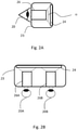
- Fig. 2B shows an embodiment of a personal display device 23, where two eyepieces 26A, 26B of the present kind are provided in binocular configuration and targeted on different portions of a single display element 24 and for both eyes 20A, 20B of a user.
- This way by presenting suitably different image content at suitable positions of the display element(s) 24 or suitably positioned display elements 24 for each eye 20A, 20B, a three-dimensional experience can be provided for the user.
- HMDs head-mounted displays
- VR virtual reality
- AR augmented reality
- the personal display system typically may contain all necessary components for producing, processing and displaying content for the user via the display element and the eyepiece or be adapted to function as a display unit only receiving the data to be displayed from an external source.
- a processing unit functionally connected to the display element, the processing unit being capable of receiving a data signal representing the content to be displayed from an external or internal source, and controlling the display element accordingly to show the content thereon.
- the processing unit is adapted to apply a software-based geometric correction on the image to be displayed, taking into account the optical distortion characteristics of the eyepiece.
- the processing unit does not perform such correction. This is also possible with the present optical system, which performs well in particular in the tele state.
- the image seen by the user may geometrically essentially correspond to that displayed in the display element.
- the display element 24 may be opaque or at least partially transparent.
- a so called see-through display device can be provided where the display device is capable of passing, in addition to the image displayed at the display element, also ambient light to the user, who sees them simultaneously.
- r is the distance from optical axis, limited by semi-diameter
- c is the surface curvature (inverse of surface radius of curvature)
- k is the conic constant
- ⁇ is the aspherical coefficient.
- the surface data of the lenses are as listed in Table 1, starting from the exit pupil (STOP) and going towards the display (DISP).
- the term “Thickness” refers to a distance between centre points of successive surfaces comprising material having properties indicated in the "Refractive index” and “Abbe number columns” (which are empty for air).
- Table 1 Lens surface data Surface # Radius of curvature [mm] Thickness [mm] Refractive index n d Abbe number V d Semi-Diameter [mm] STOP PLANO 12,00 5,00 2 -269,18 5,87 1,720 34,7 20,50 3 -30,80 0,00 20,50 4 82,24 7,93 1,720 34,7 25,00 5 -267,21 Variable 25,00 6 -158,14 1,00 1,847 23,8 25,50 7 98,86 Variable 25,50 8 67,44 6,04 1,720 34,7 25,50 9 446,27 4.044 25,50 DISP PLANO 26,55 Table 2.
- Figs 3A and 3B show distortion graphs of the exemplary eyepiece in tele and wide angle states, respectively (as seen when light is coming from the left in the configuration of Figs 1B and 1A ).
Description
- The invention relates to optics of personal display systems used in virtual reality (VR) and augmented reality (AR) applications, for example. In particular, the invention relates to varifocal eyepieces for use in personal displays and personal displays containing such eyepiece.
- Due to the recent developments and progress in the micro display and near-to-eye display (NED) technology, virtual and augmented reality headsets are becoming more common. Some products have already been launched to consumer market, mainly for virtual reality applications, gaming and other entertainment. These headsets typically comprise a wide angle eyepiece for projection, the eyepiece comprising a single lens that can be aspheric and can comprise Fresnel grooves to reduce its weight. These systems are usually not exit pupil forming as the displays typically radiate in Lambertian pattern, but regardless of this property, the projection optics nevertheless need to be designed for a specific exit pupil value for pleasant viewing experience.
- For compatibility with the human eye, the design exit pupil of the eyepiece, either nonpupil forming or pupil forming, must be located outside the lens assembly itself. The minimum recommended distance between the eyelens and the exit pupil ranges typically between 8 and 12 millimetres. This distance is also called an eye-relief. If the eye-relief is less than 8 millimetres, it is very likely that the user will mash his eyelashes against the eyepiece, which causes physical discomfort.
- For these systems, a wide field of view is very important for the sake of immersion, and typical field of views range from 115 degrees to 95 degrees for a single lens element. The image source, such as a display panel, is typically larger than the lens itself. Typical distortion obtained from the f∗tan(theta) projection law can easily exceed 50% in the existing wide angle eyepieces. This distortion is, however, of little consequence, as the distortion effect can be corrected with software, so that the user does not perceive significant distortion, and usually does not see the change of resolution at the image periphery on the display panel. This deviates from traditional eyepiece design where such distortion has not been as readily acceptable.
- Prior art VR and AR eyepiece optics designed for wide angle projection perform usually satisfactorily for the virtual or augmented reality projection application if the intention is gaming. However, this configuration is problematic once the user would like to use the headset for something else, as the image periphery in wide angle projection is not resolved well enough by prior art visual systems. While cropping the image smaller is one solution for more comfortable watching experience, this operation can easily lose more than 50% of the display pixels, whereby the image quality suffers.
- The prior art systems suggest that as much as 80% of the total image information can be lost if the field of view was cropped to 40-degree diagonal, and roughly 65% for the 60-degree diagonal. Roughly 2400 pixels along the diagonal are needed for a 40-degree viewing experience where the human vision system limits the perceived resolution (1 arc min). This would imply that a display used in the 90-110 degrees virtual reality projection would require anywhere between 5400 to 6600 pixels along the diagonal. This is outside the current realm of affordable virtual reality headsets, and thus the viewing experience will be limited by the display resolution for some years to come.
- One existing eyepiece is disclosed in
US 3768890 . The eyepiece has internal focusing implemented with two groups of lenses, and employs a variation of space between the two groups. Such eyepiece cannot however project sufficiently wide angle images for immersive VR or AR applications.US 7154683 , on the other hand, discloses an eye-piece with a configuration where every positive lens is a similar plano-convex lens. This eyepiece is not designed for continuous zooming nor can it provide the required field-of-view for wide-angle applications. -
CN106773048 discloses an HMT (head-mounted display) optical system provided with an adjustable exit pupil, comprising a front fixing group, a zooming group, a compensation group and a rear fixing group. The position relation is shown as follows: with a microdisplay or a middle image plane as an object plane, the front fixing group, the zooming group, the compensation group and the rear fixing group are arranged sequentially, and each of the front fixing group, the zooming group, the compensation group and the rear fixing group is arranged in an axial symmetry manner relative to an optical axis; the front fixing group and the rear fixing group always keep unchanged in position in the zooming process of the optical system, and the zooming group and the compensation group move along the optical axis in accordance with respective curves in the zooming process of the optical system. A front focal plane and a rear focal plane of the optical system are kept fixed in the moving process of the zooming group and the compensation group, so that the front focal plane of the optical system and the object plane coincide, and the rear focal plane of the optical system and the exit pupil coincide. The optical system has the characteristics of being simple in structure, high in light energy utilization rate, high in imaging quality and the like and can realize expansion and intelligent adjustment of the exit pupil. -
US 5757544 discloses A head-mounted image display apparatus having an exit pupil that is enlarged without causing an increase in the size of a relay optical system or a reduction in the size of a projected image. The head-mounted image display apparatus has an image display device having a display surface for displaying an image, a relay optical system for transmitting the image displayed on the display surface of the image display device to form an image of the display surface, and an ocular optical system for projecting the image transmitted by the relay optical system inside an observer's eyeball as an enlarged image. A numerical aperture (NA) enlarging element is disposed at a position conjugated with the display surface with respect to the relay optical system. Thus, pupil alignment is facilitated without causing an increase in the size of the relay optical system or a reduction in the size of the projected image. Also, provided as a technique whereby field curvature of the ocular optical system is corrected to provide a flat image for observation. - Thus, there is as need for novel eyepiece solutions for personal displays, having the capability to perform well in both wide angle and narrow angle solutions.
- It is an aim of the invention to solve at least some of the abovementioned problems and to provide an eyepiece for use in personal displays and being capable of improving user experience of personal displays. One aim is to provide an eyepiece which suits better for a wide range of applications, such as watching movies and gaming, in particular allowing for wide angle image for immersive applications and optically better image in narrow-angle image applications. Further, an aim is to allow for the utilization of the whole display area in applications requiring good optical performance also on the peripheral areas, such as corners of the display. An additional aim is to provide an eyepiece which performs optically better in both wide angle and narrow angle applications.
- A particular aim is to provide a new personal display with improved user experience and/or optical performance as described above, in particular a wearable personal device (headset) comprising a built-in display element or means for mounting an external display element and an eyepiece for projecting the image from the display to an eye of a viewer and providing an improved movie watching experience.
- The aims are achieved by the invention as herein described and claimed.
- The invention is an eyepiece as defined in appended independent claim 1.
- A personal display device according to the invention is defined in appended
claim 5. - The invention offers significant benefits. In particular, the invention allows the same display that is used for wide-angle projection to retain its pixel count in narrow projection angle application. This is accomplished by the present invention by using moving groups in suitable optical configuration to accommodate the system for the desired focal length, thus field of view, still taking advantage of the whole area of the display element. There is no need for cropping the image.
- Particular advantages are gained in applications requiring user attention within the central part of the image and still containing important details in the periphery. An example of such application is watching television or movies. This is because the image in prior art VR/AR devices is either cropped or necessarily projected onto a very wide field of view, whereby the eyes consequently need to turn relatively much from the center in order to perceive details on the periphery of the image. Consequently, the viewing experience suffers and the eyes are stressed. Especially watching movies becomes tiresome as the action happens in a very wide field of view. It is difficult to concentrate on the movie as important details may occur in the periphery, at which the human eye has poor resolution and tilting the eyeball there causes eyestrain. In addition, according to studies, people recall faces, which fit in a relatively narrow field of view, typically about 20 degrees, which is therefore also the most natural and most convenient field for faces. If only a wide-angle state is available, faces appearing on a movie, for example, appear to be too intrusive.
- The invention also provides a completely novel optical construction for a projection optics assembly that suits to be used as an eyepiece of a personal display. In particular, the optical construction provides changing the field-of-view, i.e. zooming, just by moving lens elements on one side of the image plane, i.e., on one side of the the exit pupil. In addition, it provides sufficient eye-relief for the user, and with the control of distortion, sufficient projection angle for the wide angle applications, while keeping image quality high for e.g. television or movie applications in zoomed configuration.
- By means of the invention is possible to reduce the display diagonal to roughly 60 % of the display diagonal according to commercially available prior art, and to allow the field of view to be changed from 110 degrees to 40 degrees. This is made possible in particular by the present three-lens configuration as herein described. A smaller display is beneficial, as the whole display device can be made smaller and more lightweight without compromising the attainable field-of-view or image quality. Thus, maximal user experience can be provided in a wide range of applications, including gaming and movies, for example. While utilizing all available pixels of the display element, the image can expanded or compressed in all cases for the optimal user experience, be it good immersion or convenient and stressless movie watching.
- The dependent claims are directed to selected embodiments of the invention.
- According to the invention, the eyepiece is adapted to provide an image of essentially equally sized areas of the image plane at said exit pupil in the first and second states. That is, no cropping of the image plane takes place but all pixels of the display element place at the image plane are be utilized by both states, providing maximal image quality. This is beneficial also because the display device does not need "know" which state the viewer is using but can simply use the whole available image area. It should be noted that the term "essentially equally sized areas" is used in relation to (non-)cropping the available display area. It therefore covers cases where potential image distortion takes place.
- According to the invention, the lens groups comprise a first movable positive lens group located closest to the exit pupil, a third stationary positive lens group located closest to the image plane, and a second movable negative lens group between the first lens group and the third lens group. According to the invention, the first lens group and the second lens group are adapted to move farther from the third lens group and closer to each other when moving from the first state to the second state. The configuration may resemble a so-called Donders-zoom construction, however applied to an eyepiece. This provides a variable field-of-view on the display, still keeping the binocular convergence calibration valid, or at least reduces possibilities for calibration errors, all the time in two-eye solutions. According to one embodiment, the second lens group is adapted to be in the vicinity of (e.g. essentially in contact with) the third lens group in the first state and in the vicinity of (e.g. essentially in contact with) the first lens group in the second state. This provides maximal change of field-of-view with a given total extension of the eyepiece.
- According to one embodiment, the first field of view is 100 degrees or more, such as 110 degrees or more, and even 115 degrees or more, and the second field of view is 65 degrees or less, typically 60 degrees or less, such as 50 degrees or less, and even 40 degrees or less. The first field-of-view can be chosen e.g. between 100 and 130 degrees and the second field-of-view e.g. between 30 and 65 degrees. Such zoom factor on one hand allows for sufficient projection angle for utilization of large display area close to the eyepiece in the wide angle state, and on the other hand reasonable increase of system length, yet allowing for high image quality in the zoomed state.
- According to one embodiment each of the lens groups comprises at most two lens elements, in particular at least two of the lens groups comprising only a single lens element.
- According to one embodiment, the exit pupil is located outside the lens system, i.e., at a distance from the lens groups.
- According to one embodiment, the eyepiece comprises means for continuous zooming between the first state (first field-of-view) and second state (second filed-of-view). That is, the user may immobilize the lens groups in any desired position between and including the first and second states so that a sharp image of the image plane is formed at the exit pupil.
- According to one embodiment of the personal display device, in addition to the display element and the eyepiece, the device comprises a processing unit functionally connected to the display element for displaying content on the display element, and adjusting means for changing the state of the eyepiece between the first state and the second state, i.e. suitably moving the movable lens groups.
- According to a further embodiment, the eyepiece and/or the personal display device the eyepiece is used in comprises mechanical and/or electrical adjustment means for the user to switch between the first and second states of the eyepiece.
- The display element can be an integral part of the device or a separate element attachable thereto. In particular, the display element can comprise a screen of a mobile phone, which is mountable to the personal display device such that its screen comes to the image plane of the eyepiece.
- According to one embodiment, the device comprises two similar eyepieces arranged in binocular configuration and targeted either on different portions of the same display element or on separate display elements.
- Next, selected embodiments of the invention and advantages thereof are discussed with reference to the attached drawings.
-
-
Figs. 1A and 1B show the optical configurations of the eyepiece according to one embodiment in a wide-angle state and tele state, respectively. -
Figs. 2A and 2B illustrates schematically a personal display device comprising an eyepiece of the present kind in side and top views, accordingly. -
Figs 3A and 3B show distortion graphs of an exemplary eyepiece in tele and wide angle states, respectively. - The term "eyepiece" generally refers to an optical device that is designed for projecting an image from a image plane on one side of the device through an exit pupil located on the opposite side of the device at a non-zero distance therefrom. An eyepiece of this kind allows for viewing a sharp and enlarged image of the image plane with a bare eye.
- The term "lens element" refers to a single optical lens in contrast with the term "lens group" that may comprise either a single lens or two or more lenses in a predefined mutual configuration.
- The term "wide angle" state (first state) here refers to a field of view of 100 degrees or more and the term "tele" or "zoomed" state (second state) to a field of view of 65 degrees or less.
- In
Figs. 1A and 1B , an outline of an exemplary lens system of an eyepiece is shown in wide-angle and narrow-angle viewing configurations, respectively. The image plane, such as a display surface, is herein denoted withreference numeral 14, whereas the exit pupil is denoted withreference numeral 10. A support structure of the lens system is not shown, but it is understood by a skilled person that some kind of a mechanical structure for holding the necessary lens groups and allowing for moving the movable lens groups must be provided to form an operational eyepiece. Various such structures are known per se. - There is provided a negative middle lens group 12 (second lens group), which is surrounded by positive lens groups 11 (first lens group) and 13 (third lens group). The
second lens group 12 acts as a variator lens group. Thethird lens group 13 is closest to and fixed with respect to adisplay 14, whereas the first andsecond lens groups - In general, each
lens group - According to one embodiment, the
first lens group 11 comprises, preferably consists of, twolens elements first lens element 11A, which comes closest to the eye, is a plano-convex lens with the planar surface facing towards the eye, whereas the neighboringsecond lens element 11B is a meniscus lens or the like. According to one embodiment, thesecond lens element 11B is a positive meniscus lens, although in some configurations it may also be a negative meniscus lens. Typically, thesecond lens element 11B is asperical like shown inFigs. 1A and 1B . It should be noted that the lenses are not necessarily directly classifiable to any single category but have custom aspheric features. - According to an alternative embodiment, the
first lens group 11 comprises, in particular consists of, a single Fresnel lens element. However, a two-lens solution is preferred for image quality reasons. - According to one embodiment, the
second lens group 12 comprises, preferably consists of, a plano-concave lens element 12A, with the planar side facing thethird lens group 13 and thedisplay 14. - According to one embodiment, the
third lens group 13 comprises, preferably consist of, a wavefrontcorrector lens element 13A, which serves to correct the shape of the wavefront close to the image source. Typically, thethird lens element 13A is aspheric. The third lens is static with respect to the display. - According to one embodiment, the first and
second lens groups - According to an alternative embodiment, the
first lens group 11 is stationary andlens groups groups - The zoom factor is mainly limited by the increase of the system length. The presented extendable structure is preferred in applications where the shortest possible dimension of the eyepiece in the wide angle state is desired.
- In some embodiments, the exit pupil is located at a distance of at least 8 mm from the lens groups. This allows for convenient viewing and prevents eyelashes from hitting the eyepiece.
- There may also be provided diopter adjustment means, which are known per se, functionally connected to the eyepiece.
-
Fig. 2A shows apersonal display 23 according to one embodiment. Thedisplay 23 comprises adisplay element 24 and aneyepiece 26 of the present kind positioned so that thedisplay element 24 covers the entire field-of-view α of theeyepiece 26 in wide angle state (and consequently also in the tele state). Thus, the viewer'seye 20, brought close to or at the exit pupil, will catch the image presented of at the display element. -
Fig. 2B shows an embodiment of apersonal display device 23, where twoeyepieces single display element 24 and for botheyes display elements 24 for eacheye - The term personal display system, as herein used, refers to a display system intended to be viewed by a single person. Examples of personal display systems include various head-mounted displays (HMDs), such as virtual reality (VR) devices, augmented reality (AR) devices and so-called wearable smart display devices.
- The personal display system typically may contain all necessary components for producing, processing and displaying content for the user via the display element and the eyepiece or be adapted to function as a display unit only receiving the data to be displayed from an external source. Typically, in a minimum configuration, there is provided a processing unit functionally connected to the display element, the processing unit being capable of receiving a data signal representing the content to be displayed from an external or internal source, and controlling the display element accordingly to show the content thereon.
- According to one embodiment, the processing unit is adapted to apply a software-based geometric correction on the image to be displayed, taking into account the optical distortion characteristics of the eyepiece. In an alternative embodiment, the processing unit does not perform such correction. This is also possible with the present optical system, which performs well in particular in the tele state. Thus, the image seen by the user may geometrically essentially correspond to that displayed in the display element.
- The
display element 24 may be opaque or at least partially transparent. In the latter case, a so called see-through display device can be provided where the display device is capable of passing, in addition to the image displayed at the display element, also ambient light to the user, who sees them simultaneously. - An exemplary lens configuration that is schematically represented by
Figs. 1A and 1B is represented by the surface parametrization formula
- In one example, the surface data of the lenses are as listed in Table 1, starting from the exit pupil (STOP) and going towards the display (DISP). The term "Thickness" refers to a distance between centre points of successive surfaces comprising material having properties indicated in the "Refractive index" and "Abbe number columns" (which are empty for air).
- Exemplary aspherical coefficients of the surfaces are listed in Table 2.
- Exemplary design thicknesses are shown in Table 3.
- General properties of the exemplary eyepiece are given in Table 4.
Table 1. Lens surface data Surface # Radius of curvature [mm] Thickness [mm] Refractive index nd Abbe number Vd Semi-Diameter [mm] STOP PLANO 12,00 5,00 2 -269,18 5,87 1,720 34,7 20,50 3 -30,80 0,00 20,50 4 82,24 7,93 1,720 34,7 25,00 5 -267,21 Variable 25,00 6 -158,14 1,00 1,847 23,8 25,50 7 98,86 Variable 25,50 8 67,44 6,04 1,720 34,7 25,50 9 446,27 4.044 25,50 DISP PLANO 26,55 Table 2. Aspherical coefficients of lens surfaces Surface # Conic constant k α1 α2 α3 α4 α5 2 0,00 0 2,260E-05 -3,374E-08 -7,406E-11 1,709E-13 3 0,00 0 2,662E-05 -1,529E-08 6,230E-11 -1,472E-13 4 0,00 0 4,485E-06 5,025E-10 -9,258E-13 -4,686 E-15 5 0,00 0 -2,438E-07 -1,355E-09 2,454E-13 -2,076E-15 8 0,00 0 -7,238E-07 -1,720E-09 -2,296E-12 6,074E-17 9 0,00 0 -3,283E-06 -1,413E-09 -2,313E-13 -1,070E-15 Table 3. Lens thicknesses Surface # Wide Tele 5 18,354 0,381 7 0 31,82 Table 4.Eyepiece properties Property Wide Tele Focal length 32,14 44,86 F/# 3,18 4,47 FFOV [dgr] 110 60,5 Distortion % 41,9 4 Total length 69,06 55,27 -
Figs 3A and 3B show distortion graphs of the exemplary eyepiece in tele and wide angle states, respectively (as seen when light is coming from the left in the configuration ofFigs 1B and 1A ).
Claims (9)
- An eyepiece, for projecting an image from an image plane (14) on one side of the eyepiece to a viewer's eye located at an exit pupil (10) on the opposite side of the eyepiece, comprising- at least one stationary lens group (13) and at least two movable lens groups (11, 12) being movable with respect to the stationary lens group (13) along an optical axis between the image plane (14) and the exit pupil (10),wherein the lens groups (11, 12, 13) are arranged in positive-negative-positive configuration and the movable lens groups (11, 12) are arranged to move along the optical axis between a first state providing a first field-of-view and a second state providing a second field-of-view smaller than the first field-of-view to the image plane (14), whereby the length of the eyepiece changes when moving between the first state and second state, and the eyepiece is adapted to provide an image of essentially equally sized area of the image plane (14) at said exit pupil (10) in said first and second states,
wherein the lens groups comprise- a first movable positive lens group (11) located closest to the exit pupil (10),- a third stationary positive lens group (13) located closest to the image plane,- a second movable negative lens group (12) between the first lens group (11) and the third lens group (13),whereby the first lens group (11) and the second lens group (12) are adapted to move farther from the third lens group (13) and closer to each other when moving from the first state to the second state. - The eyepiece according to claim 1, wherein the second lens group (12) is adapted to be in the vicinity of the third lens group (13) in the first state and in the vicinity of the first lens group (11) in the second state.
- The eyepiece according to any of the preceding claims, wherein the first field-of-view is 100 degrees or more and the second field-of-view is 65 degrees or less.
- The eyepiece according to any of the preceding claims, wherein each of the lens groups (11, 12, 13) comprises at most two lens elements (11A, 11B, 12A, 13A), in particular at least two of the lens groups (12, 13) comprising only a single lens element (12A, 13A).
- A personal display device (23) comprising- a display element (24) or means for mounting a display element in a fixed position,- an eyepiece (26) for projecting an image from the display element (24) to an eye (20) of a viewer,wherein the eyepiece (26) comprises an eyepiece (26) according to any of the preceding claims, whereby the display element (24) is positioned at said image plane (14).
- The display device according to claim 5, comprising a processing unit functionally connected to the display element for displaying content on the display element.
- The display device according to claim 5 or 6, comprising eyepiece adjusting means adapted to allow for changing of the state of the eyepiece (26) between the first state and the second state.
- The display device according to any of claims 5 - 7, comprising two such eyepieces (26A, 26B) in binocular configuration.
- The display device according to any of claims 5 - 8, wherein the device is a wearable device.
Applications Claiming Priority (2)
| Application Number | Priority Date | Filing Date | Title |
|---|---|---|---|
| FI20175502A FI128248B (en) | 2017-06-02 | 2017-06-02 | Eyepiece for a personal display and personal display comprising such eyepiece |
| PCT/FI2018/050372 WO2018220267A1 (en) | 2017-06-02 | 2018-05-18 | Eyepiece for a personal display and personal display comprising such eyepiece |
Publications (3)
| Publication Number | Publication Date |
|---|---|
| EP3631568A1 EP3631568A1 (en) | 2020-04-08 |
| EP3631568A4 EP3631568A4 (en) | 2021-03-10 |
| EP3631568B1 true EP3631568B1 (en) | 2022-03-02 |
Family
ID=64456160
Family Applications (1)
| Application Number | Title | Priority Date | Filing Date |
|---|---|---|---|
| EP18810419.4A Active EP3631568B1 (en) | 2017-06-02 | 2018-05-18 | Eyepiece for a personal display and personal display comprising such eyepiece |
Country Status (7)
| Country | Link |
|---|---|
| US (1) | US11237380B2 (en) |
| EP (1) | EP3631568B1 (en) |
| JP (1) | JP7177356B2 (en) |
| CN (1) | CN111033356B (en) |
| ES (1) | ES2909121T3 (en) |
| FI (1) | FI128248B (en) |
| WO (1) | WO2018220267A1 (en) |
Family Cites Families (22)
| Publication number | Priority date | Publication date | Assignee | Title |
|---|---|---|---|---|
| DE1814132C3 (en) | 1968-12-12 | 1981-02-26 | Ernst Leitz Wetzlar Gmbh, 6330 Wetzlar | Pancratic eyepiece, especially for microphotography |
| US3768890A (en) | 1971-06-12 | 1973-10-30 | Nippon Kogaku Kk | Internal focusing wide angle eyepiece |
| JPS6292909A (en) * | 1985-10-18 | 1987-04-28 | Olympus Optical Co Ltd | Vari-focal lens |
| JPH03287217A (en) * | 1990-04-03 | 1991-12-17 | Minolta Camera Co Ltd | Finder optical system |
| US5757544A (en) | 1993-03-09 | 1998-05-26 | Olympus Optical Co., Ltd. | Image display apparatus |
| JP3710188B2 (en) * | 1996-01-08 | 2005-10-26 | キヤノン株式会社 | Viewfinder optical system |
| US5749008A (en) * | 1996-01-18 | 1998-05-05 | Minolta | Eyepiece |
| JPH11133317A (en) * | 1997-10-31 | 1999-05-21 | Asahi Optical Co Ltd | Zoom magnifier |
| US6312129B1 (en) | 1998-07-21 | 2001-11-06 | L-3 Communications Corp. | Head mounted projector system |
| JP4573378B2 (en) * | 1999-11-12 | 2010-11-04 | オリンパス株式会社 | Zoom lens |
| JP3402318B2 (en) | 2000-09-04 | 2003-05-06 | ミノルタ株式会社 | Imaging device |
| JP3713250B2 (en) * | 2002-04-18 | 2005-11-09 | ペンタックス株式会社 | Eyepiece variable magnification optical system |
| JP3755036B2 (en) | 2002-09-02 | 2006-03-15 | 国立大学法人大阪大学 | Wide viewing angle head mounted display device |
| US7154683B1 (en) | 2005-07-06 | 2006-12-26 | Brian E Volk | Five-element optical device |
| JP5642699B2 (en) | 2008-11-26 | 2014-12-17 | ポケット・オプティックス・デベロップメント・コーポレイションPocket Optics Development Corporation | Improved binocular observation device |
| KR20130000401A (en) * | 2010-02-28 | 2013-01-02 | 오스터하우트 그룹 인코포레이티드 | Local advertising content on an interactive head-mounted eyepiece |
| US8994611B2 (en) | 2010-03-24 | 2015-03-31 | Olympus Corporation | Head-mounted type display device |
| CN104049368B (en) * | 2014-06-19 | 2016-08-24 | 浙江晶景光电有限公司 | A kind of interpupillary distance adjustable penetration video eyeglasses optical engine system |
| CN106680997A (en) | 2015-11-05 | 2017-05-17 | 丰唐物联技术(深圳)有限公司 | Display control method and display control device |
| CN107683432B (en) | 2015-11-13 | 2021-05-28 | 深圳纳德光学有限公司 | Eyepiece optical system with large field angle and head-mounted display device |
| JP2018060041A (en) * | 2016-10-05 | 2018-04-12 | 株式会社ニコン | Eyepiece optical system, optical apparatus and method for manufacturing eyepiece optical system |
| CN106773048B (en) | 2016-12-27 | 2023-08-04 | 塔普翊海(上海)智能科技有限公司 | Head-mounted display optical system with adjustable exit pupil |
-
2017
- 2017-06-02 FI FI20175502A patent/FI128248B/en active IP Right Grant
-
2018
- 2018-05-18 US US16/618,131 patent/US11237380B2/en active Active
- 2018-05-18 JP JP2019566769A patent/JP7177356B2/en active Active
- 2018-05-18 WO PCT/FI2018/050372 patent/WO2018220267A1/en active Application Filing
- 2018-05-18 ES ES18810419T patent/ES2909121T3/en active Active
- 2018-05-18 CN CN201880038541.XA patent/CN111033356B/en active Active
- 2018-05-18 EP EP18810419.4A patent/EP3631568B1/en active Active
Also Published As
| Publication number | Publication date |
|---|---|
| FI20175502A1 (en) | 2018-12-03 |
| WO2018220267A1 (en) | 2018-12-06 |
| ES2909121T3 (en) | 2022-05-05 |
| EP3631568A4 (en) | 2021-03-10 |
| CN111033356A (en) | 2020-04-17 |
| US11237380B2 (en) | 2022-02-01 |
| EP3631568A1 (en) | 2020-04-08 |
| US20200116991A1 (en) | 2020-04-16 |
| FI128248B (en) | 2020-01-31 |
| JP2020522022A (en) | 2020-07-27 |
| CN111033356B (en) | 2022-08-02 |
| JP7177356B2 (en) | 2022-11-24 |
Similar Documents
| Publication | Publication Date | Title |
|---|---|---|
| JP3487859B2 (en) | Head mounted display device and display optical system used in the device | |
| CN103995355B (en) | The optical system of a kind of adjustable diopter for Helmet Mounted Display | |
| US8159751B2 (en) | Apparatus for head mounted image display | |
| CN104932104B (en) | A kind of variable-focus optical system and head-up-display system | |
| JP3524925B2 (en) | Wide-angle binoculars with variable performance | |
| KR20180104056A (en) | Wide Field Private Display | |
| US11073688B2 (en) | Virtual reality head mounted display having planar fresnel surface | |
| CN107209381A (en) | Hybrid lens system for head-mountable display | |
| TW201921029A (en) | Wide field personal display device | |
| JP2006209138A (en) | Head-mounted display system with aspheric optics | |
| WO2020079906A1 (en) | Head-mounted display and method for designing wide-focus lens used in same | |
| EP1251384B1 (en) | High performance viewfinder eyepiece with a large diopter focus range | |
| EP3032313B1 (en) | Ocular lens system, and image observation device | |
| CN106054390A (en) | Display device and head-mounted device using the same | |
| EP3929649A1 (en) | Large-field-of-view high-image-quality eyepiece optical system and device | |
| CN115236847B (en) | Eyepiece optical system and head-mounted display device | |
| EP3631568B1 (en) | Eyepiece for a personal display and personal display comprising such eyepiece | |
| US10520720B2 (en) | Large format biocular lens | |
| US10261332B1 (en) | Eyepiece lens with protected Fresnel and diffractive surfaces | |
| JP3355779B2 (en) | Optical system for HMD | |
| JP2020024363A (en) | Display device | |
| US20230324660A1 (en) | Optical system | |
| JP3833207B2 (en) | Display device | |
| WO2020026749A1 (en) | Display device | |
| WO2020026813A1 (en) | Display device |
Legal Events
| Date | Code | Title | Description |
|---|---|---|---|
| STAA | Information on the status of an ep patent application or granted ep patent |
Free format text: STATUS: THE INTERNATIONAL PUBLICATION HAS BEEN MADE |
|
| PUAI | Public reference made under article 153(3) epc to a published international application that has entered the european phase |
Free format text: ORIGINAL CODE: 0009012 |
|
| STAA | Information on the status of an ep patent application or granted ep patent |
Free format text: STATUS: REQUEST FOR EXAMINATION WAS MADE |
|
| 17P | Request for examination filed |
Effective date: 20191127 |
|
| AK | Designated contracting states |
Kind code of ref document: A1 Designated state(s): AL AT BE BG CH CY CZ DE DK EE ES FI FR GB GR HR HU IE IS IT LI LT LU LV MC MK MT NL NO PL PT RO RS SE SI SK SM TR |
|
| AX | Request for extension of the european patent |
Extension state: BA ME |
|
| DAV | Request for validation of the european patent (deleted) | ||
| DAX | Request for extension of the european patent (deleted) | ||
| A4 | Supplementary search report drawn up and despatched |
Effective date: 20210208 |
|
| RIC1 | Information provided on ipc code assigned before grant |
Ipc: G02B 25/00 20060101ALI20210202BHEP Ipc: G02B 27/01 20060101AFI20210202BHEP Ipc: G02B 25/04 20060101ALI20210202BHEP |
|
| GRAP | Despatch of communication of intention to grant a patent |
Free format text: ORIGINAL CODE: EPIDOSNIGR1 |
|
| STAA | Information on the status of an ep patent application or granted ep patent |
Free format text: STATUS: GRANT OF PATENT IS INTENDED |
|
| INTG | Intention to grant announced |
Effective date: 20211027 |
|
| GRAS | Grant fee paid |
Free format text: ORIGINAL CODE: EPIDOSNIGR3 |
|
| GRAA | (expected) grant |
Free format text: ORIGINAL CODE: 0009210 |
|
| STAA | Information on the status of an ep patent application or granted ep patent |
Free format text: STATUS: THE PATENT HAS BEEN GRANTED |
|
| AK | Designated contracting states |
Kind code of ref document: B1 Designated state(s): AL AT BE BG CH CY CZ DE DK EE ES FI FR GB GR HR HU IE IS IT LI LT LU LV MC MK MT NL NO PL PT RO RS SE SI SK SM TR |
|
| REG | Reference to a national code |
Ref country code: GB Ref legal event code: FG4D |
|
| REG | Reference to a national code |
Ref country code: CH Ref legal event code: EP Ref country code: AT Ref legal event code: REF Ref document number: 1472736 Country of ref document: AT Kind code of ref document: T Effective date: 20220315 |
|
| REG | Reference to a national code |
Ref country code: DE Ref legal event code: R096 Ref document number: 602018031736 Country of ref document: DE |
|
| REG | Reference to a national code |
Ref country code: IE Ref legal event code: FG4D |
|
| REG | Reference to a national code |
Ref country code: NL Ref legal event code: FP |
|
| REG | Reference to a national code |
Ref country code: ES Ref legal event code: FG2A Ref document number: 2909121 Country of ref document: ES Kind code of ref document: T3 Effective date: 20220505 |
|
| REG | Reference to a national code |
Ref country code: LT Ref legal event code: MG9D |
|
| PG25 | Lapsed in a contracting state [announced via postgrant information from national office to epo] |
Ref country code: SE Free format text: LAPSE BECAUSE OF FAILURE TO SUBMIT A TRANSLATION OF THE DESCRIPTION OR TO PAY THE FEE WITHIN THE PRESCRIBED TIME-LIMIT Effective date: 20220302 Ref country code: RS Free format text: LAPSE BECAUSE OF FAILURE TO SUBMIT A TRANSLATION OF THE DESCRIPTION OR TO PAY THE FEE WITHIN THE PRESCRIBED TIME-LIMIT Effective date: 20220302 Ref country code: NO Free format text: LAPSE BECAUSE OF FAILURE TO SUBMIT A TRANSLATION OF THE DESCRIPTION OR TO PAY THE FEE WITHIN THE PRESCRIBED TIME-LIMIT Effective date: 20220602 Ref country code: LT Free format text: LAPSE BECAUSE OF FAILURE TO SUBMIT A TRANSLATION OF THE DESCRIPTION OR TO PAY THE FEE WITHIN THE PRESCRIBED TIME-LIMIT Effective date: 20220302 Ref country code: HR Free format text: LAPSE BECAUSE OF FAILURE TO SUBMIT A TRANSLATION OF THE DESCRIPTION OR TO PAY THE FEE WITHIN THE PRESCRIBED TIME-LIMIT Effective date: 20220302 Ref country code: BG Free format text: LAPSE BECAUSE OF FAILURE TO SUBMIT A TRANSLATION OF THE DESCRIPTION OR TO PAY THE FEE WITHIN THE PRESCRIBED TIME-LIMIT Effective date: 20220602 |
|
| PG25 | Lapsed in a contracting state [announced via postgrant information from national office to epo] |
Ref country code: PL Free format text: LAPSE BECAUSE OF FAILURE TO SUBMIT A TRANSLATION OF THE DESCRIPTION OR TO PAY THE FEE WITHIN THE PRESCRIBED TIME-LIMIT Effective date: 20220302 Ref country code: LV Free format text: LAPSE BECAUSE OF FAILURE TO SUBMIT A TRANSLATION OF THE DESCRIPTION OR TO PAY THE FEE WITHIN THE PRESCRIBED TIME-LIMIT Effective date: 20220302 Ref country code: GR Free format text: LAPSE BECAUSE OF FAILURE TO SUBMIT A TRANSLATION OF THE DESCRIPTION OR TO PAY THE FEE WITHIN THE PRESCRIBED TIME-LIMIT Effective date: 20220603 Ref country code: FI Free format text: LAPSE BECAUSE OF FAILURE TO SUBMIT A TRANSLATION OF THE DESCRIPTION OR TO PAY THE FEE WITHIN THE PRESCRIBED TIME-LIMIT Effective date: 20220302 |
|
| PG25 | Lapsed in a contracting state [announced via postgrant information from national office to epo] |
Ref country code: SM Free format text: LAPSE BECAUSE OF FAILURE TO SUBMIT A TRANSLATION OF THE DESCRIPTION OR TO PAY THE FEE WITHIN THE PRESCRIBED TIME-LIMIT Effective date: 20220302 Ref country code: SK Free format text: LAPSE BECAUSE OF FAILURE TO SUBMIT A TRANSLATION OF THE DESCRIPTION OR TO PAY THE FEE WITHIN THE PRESCRIBED TIME-LIMIT Effective date: 20220302 Ref country code: RO Free format text: LAPSE BECAUSE OF FAILURE TO SUBMIT A TRANSLATION OF THE DESCRIPTION OR TO PAY THE FEE WITHIN THE PRESCRIBED TIME-LIMIT Effective date: 20220302 Ref country code: PT Free format text: LAPSE BECAUSE OF FAILURE TO SUBMIT A TRANSLATION OF THE DESCRIPTION OR TO PAY THE FEE WITHIN THE PRESCRIBED TIME-LIMIT Effective date: 20220704 Ref country code: EE Free format text: LAPSE BECAUSE OF FAILURE TO SUBMIT A TRANSLATION OF THE DESCRIPTION OR TO PAY THE FEE WITHIN THE PRESCRIBED TIME-LIMIT Effective date: 20220302 Ref country code: CZ Free format text: LAPSE BECAUSE OF FAILURE TO SUBMIT A TRANSLATION OF THE DESCRIPTION OR TO PAY THE FEE WITHIN THE PRESCRIBED TIME-LIMIT Effective date: 20220302 |
|
| PG25 | Lapsed in a contracting state [announced via postgrant information from national office to epo] |
Ref country code: IS Free format text: LAPSE BECAUSE OF FAILURE TO SUBMIT A TRANSLATION OF THE DESCRIPTION OR TO PAY THE FEE WITHIN THE PRESCRIBED TIME-LIMIT Effective date: 20220702 Ref country code: AL Free format text: LAPSE BECAUSE OF FAILURE TO SUBMIT A TRANSLATION OF THE DESCRIPTION OR TO PAY THE FEE WITHIN THE PRESCRIBED TIME-LIMIT Effective date: 20220302 |
|
| REG | Reference to a national code |
Ref country code: DE Ref legal event code: R097 Ref document number: 602018031736 Country of ref document: DE |
|
| REG | Reference to a national code |
Ref country code: CH Ref legal event code: PL |
|
| PLBE | No opposition filed within time limit |
Free format text: ORIGINAL CODE: 0009261 |
|
| STAA | Information on the status of an ep patent application or granted ep patent |
Free format text: STATUS: NO OPPOSITION FILED WITHIN TIME LIMIT |
|
| REG | Reference to a national code |
Ref country code: BE Ref legal event code: MM Effective date: 20220531 |
|
| PG25 | Lapsed in a contracting state [announced via postgrant information from national office to epo] |
Ref country code: MC Free format text: LAPSE BECAUSE OF FAILURE TO SUBMIT A TRANSLATION OF THE DESCRIPTION OR TO PAY THE FEE WITHIN THE PRESCRIBED TIME-LIMIT Effective date: 20220302 Ref country code: LU Free format text: LAPSE BECAUSE OF NON-PAYMENT OF DUE FEES Effective date: 20220518 Ref country code: LI Free format text: LAPSE BECAUSE OF NON-PAYMENT OF DUE FEES Effective date: 20220531 Ref country code: DK Free format text: LAPSE BECAUSE OF FAILURE TO SUBMIT A TRANSLATION OF THE DESCRIPTION OR TO PAY THE FEE WITHIN THE PRESCRIBED TIME-LIMIT Effective date: 20220302 Ref country code: CH Free format text: LAPSE BECAUSE OF NON-PAYMENT OF DUE FEES Effective date: 20220531 |
|
| 26N | No opposition filed |
Effective date: 20221205 |
|
| PG25 | Lapsed in a contracting state [announced via postgrant information from national office to epo] |
Ref country code: SI Free format text: LAPSE BECAUSE OF FAILURE TO SUBMIT A TRANSLATION OF THE DESCRIPTION OR TO PAY THE FEE WITHIN THE PRESCRIBED TIME-LIMIT Effective date: 20220302 |
|
| PG25 | Lapsed in a contracting state [announced via postgrant information from national office to epo] |
Ref country code: IE Free format text: LAPSE BECAUSE OF NON-PAYMENT OF DUE FEES Effective date: 20220518 |
|
| PG25 | Lapsed in a contracting state [announced via postgrant information from national office to epo] |
Ref country code: BE Free format text: LAPSE BECAUSE OF NON-PAYMENT OF DUE FEES Effective date: 20220531 |
|
| P01 | Opt-out of the competence of the unified patent court (upc) registered |
Effective date: 20230527 |
|
| REG | Reference to a national code |
Ref country code: AT Ref legal event code: UEP Ref document number: 1472736 Country of ref document: AT Kind code of ref document: T Effective date: 20220302 |
|
| PGFP | Annual fee paid to national office [announced via postgrant information from national office to epo] |
Ref country code: NL Payment date: 20230526 Year of fee payment: 6 Ref country code: IT Payment date: 20230519 Year of fee payment: 6 Ref country code: FR Payment date: 20230525 Year of fee payment: 6 Ref country code: ES Payment date: 20230601 Year of fee payment: 6 Ref country code: DE Payment date: 20230530 Year of fee payment: 6 |
|
| PGFP | Annual fee paid to national office [announced via postgrant information from national office to epo] |
Ref country code: AT Payment date: 20230504 Year of fee payment: 6 |
|
| PGFP | Annual fee paid to national office [announced via postgrant information from national office to epo] |
Ref country code: GB Payment date: 20230529 Year of fee payment: 6 |