KR20180104056A - Wide Field Private Display - Google Patents
Wide Field Private Display Download PDFInfo
- Publication number
- KR20180104056A KR20180104056A KR1020187023889A KR20187023889A KR20180104056A KR 20180104056 A KR20180104056 A KR 20180104056A KR 1020187023889 A KR1020187023889 A KR 1020187023889A KR 20187023889 A KR20187023889 A KR 20187023889A KR 20180104056 A KR20180104056 A KR 20180104056A
- Authority
- KR
- South Korea
- Prior art keywords
- lens
- beam splitter
- image generator
- image
- viewer
- Prior art date
Links
Images


Classifications
-
- G—PHYSICS
- G02—OPTICS
- G02B—OPTICAL ELEMENTS, SYSTEMS OR APPARATUS
- G02B27/00—Optical systems or apparatus not provided for by any of the groups G02B1/00 - G02B26/00, G02B30/00
- G02B27/01—Head-up displays
- G02B27/017—Head mounted
- G02B27/0172—Head mounted characterised by optical features
-
- G—PHYSICS
- G02—OPTICS
- G02B—OPTICAL ELEMENTS, SYSTEMS OR APPARATUS
- G02B27/00—Optical systems or apparatus not provided for by any of the groups G02B1/00 - G02B26/00, G02B30/00
- G02B27/01—Head-up displays
- G02B27/017—Head mounted
- G02B27/0176—Head mounted characterised by mechanical features
-
- G—PHYSICS
- G02—OPTICS
- G02B—OPTICAL ELEMENTS, SYSTEMS OR APPARATUS
- G02B1/00—Optical elements characterised by the material of which they are made; Optical coatings for optical elements
- G02B1/04—Optical elements characterised by the material of which they are made; Optical coatings for optical elements made of organic materials, e.g. plastics
- G02B1/041—Lenses
-
- G—PHYSICS
- G02—OPTICS
- G02B—OPTICAL ELEMENTS, SYSTEMS OR APPARATUS
- G02B1/00—Optical elements characterised by the material of which they are made; Optical coatings for optical elements
- G02B1/10—Optical coatings produced by application to, or surface treatment of, optical elements
- G02B1/11—Anti-reflection coatings
-
- G—PHYSICS
- G02—OPTICS
- G02B—OPTICAL ELEMENTS, SYSTEMS OR APPARATUS
- G02B1/00—Optical elements characterised by the material of which they are made; Optical coatings for optical elements
- G02B1/10—Optical coatings produced by application to, or surface treatment of, optical elements
- G02B1/18—Coatings for keeping optical surfaces clean, e.g. hydrophobic or photo-catalytic films
-
- G—PHYSICS
- G02—OPTICS
- G02B—OPTICAL ELEMENTS, SYSTEMS OR APPARATUS
- G02B17/00—Systems with reflecting surfaces, with or without refracting elements
- G02B17/08—Catadioptric systems
- G02B17/0856—Catadioptric systems comprising a refractive element with a reflective surface, the reflection taking place inside the element, e.g. Mangin mirrors
- G02B17/086—Catadioptric systems comprising a refractive element with a reflective surface, the reflection taking place inside the element, e.g. Mangin mirrors wherein the system is made of a single block of optical material, e.g. solid catadioptric systems
-
- G—PHYSICS
- G02—OPTICS
- G02B—OPTICAL ELEMENTS, SYSTEMS OR APPARATUS
- G02B27/00—Optical systems or apparatus not provided for by any of the groups G02B1/00 - G02B26/00, G02B30/00
- G02B27/0006—Optical systems or apparatus not provided for by any of the groups G02B1/00 - G02B26/00, G02B30/00 with means to keep optical surfaces clean, e.g. by preventing or removing dirt, stains, contamination, condensation
-
- G—PHYSICS
- G02—OPTICS
- G02B—OPTICAL ELEMENTS, SYSTEMS OR APPARATUS
- G02B27/00—Optical systems or apparatus not provided for by any of the groups G02B1/00 - G02B26/00, G02B30/00
- G02B27/01—Head-up displays
- G02B27/0179—Display position adjusting means not related to the information to be displayed
-
- G—PHYSICS
- G02—OPTICS
- G02B—OPTICAL ELEMENTS, SYSTEMS OR APPARATUS
- G02B27/00—Optical systems or apparatus not provided for by any of the groups G02B1/00 - G02B26/00, G02B30/00
- G02B27/10—Beam splitting or combining systems
- G02B27/1066—Beam splitting or combining systems for enhancing image performance, like resolution, pixel numbers, dual magnifications or dynamic range, by tiling, slicing or overlapping fields of view
-
- G—PHYSICS
- G02—OPTICS
- G02B—OPTICAL ELEMENTS, SYSTEMS OR APPARATUS
- G02B27/00—Optical systems or apparatus not provided for by any of the groups G02B1/00 - G02B26/00, G02B30/00
- G02B27/28—Optical systems or apparatus not provided for by any of the groups G02B1/00 - G02B26/00, G02B30/00 for polarising
- G02B27/283—Optical systems or apparatus not provided for by any of the groups G02B1/00 - G02B26/00, G02B30/00 for polarising used for beam splitting or combining
-
- G—PHYSICS
- G02—OPTICS
- G02B—OPTICAL ELEMENTS, SYSTEMS OR APPARATUS
- G02B5/00—Optical elements other than lenses
- G02B5/30—Polarising elements
- G02B5/3083—Birefringent or phase retarding elements
-
- G—PHYSICS
- G02—OPTICS
- G02B—OPTICAL ELEMENTS, SYSTEMS OR APPARATUS
- G02B27/00—Optical systems or apparatus not provided for by any of the groups G02B1/00 - G02B26/00, G02B30/00
- G02B27/01—Head-up displays
- G02B27/0101—Head-up displays characterised by optical features
- G02B2027/011—Head-up displays characterised by optical features comprising device for correcting geometrical aberrations, distortion
-
- G—PHYSICS
- G02—OPTICS
- G02B—OPTICAL ELEMENTS, SYSTEMS OR APPARATUS
- G02B27/00—Optical systems or apparatus not provided for by any of the groups G02B1/00 - G02B26/00, G02B30/00
- G02B27/01—Head-up displays
- G02B27/0101—Head-up displays characterised by optical features
- G02B2027/0132—Head-up displays characterised by optical features comprising binocular systems
-
- G—PHYSICS
- G02—OPTICS
- G02B—OPTICAL ELEMENTS, SYSTEMS OR APPARATUS
- G02B27/00—Optical systems or apparatus not provided for by any of the groups G02B1/00 - G02B26/00, G02B30/00
- G02B27/01—Head-up displays
- G02B27/0101—Head-up displays characterised by optical features
- G02B2027/0138—Head-up displays characterised by optical features comprising image capture systems, e.g. camera
-
- G—PHYSICS
- G02—OPTICS
- G02B—OPTICAL ELEMENTS, SYSTEMS OR APPARATUS
- G02B27/00—Optical systems or apparatus not provided for by any of the groups G02B1/00 - G02B26/00, G02B30/00
- G02B27/01—Head-up displays
- G02B27/0149—Head-up displays characterised by mechanical features
- G02B2027/0154—Head-up displays characterised by mechanical features with movable elements
Abstract
디스플레이 기기는 표면으로부터 이미지를 포함하는 빛을 발생하는 이미지 발생기와 상기 이미지 발생기로부터 이격되고 상기 이미지 발생기에 대해 오목한 비구면 입사 굴절 표면 및 비구면 반사 표면을 가진 렌즈를 가지며, 상기 반사 표면의 주축은 상기 이미지 발생기에 대해 수직하다. 상기 이미지 발생기와 렌즈 사이의 자유 공간에 배치된 빔 스플리터는 보는 사람의 시선에 대해 비스듬한 제1 및 제2 평행한 표면을 갖는다. 상기 렌즈 및 빔 스플리터 플레이트는 보는 사람의 시선을 따른 이미지를 포함하는 빛을 위한 뷰어 아이 박스를 형성한다.The display device having an image generator for generating light comprising an image from a surface and a lens spaced from the image generator and having an aspherical incidence and refraction surface concave to the image generator, It is perpendicular to the generator. The beam splitter disposed in the free space between the image generator and the lens has first and second parallel surfaces that are oblique to the line of sight of the viewer. The lens and beam splitter plate form a viewer eye box for light including an image along the line of sight of the viewer.
Description
본 출원은 2016년 1월 22일 출원한 미국 가출원 번호 62/286,019와, 2016년 10월 11일 출원한 미국 가출원 번호 62/406,674, 및 2016년 9월 20일 출원한 미국 가출원 번호 62/397,138의 우선권을 주장하며, 그 내용은 전체가 참조로서 본원에 포함된다.This application claims the benefit of U.S. Provisional Application No. 62 / 286,019, filed January 22, 2016, U.S. Provisional Application No. 62 / 406,674, filed October 11, 2016, and U.S. Provisional Application No. 62 / 397,138 filed on September 20, The contents of which are incorporated herein by reference in their entirety.
본 발명은 일반적으로 개인 디스플레이에 관한 것으로서, 더욱 구체적으로는 동공 이미징 시스템을 가진 와이드-필드 헤드-장착 디스플레이 또는 다른 단일-보는 사람(viewer) 디스플레이를 위한 장치 및 방법에 대한 것이다.FIELD OF THE INVENTION The present invention relates generally to personal displays and, more particularly, to apparatus and methods for a wide-field head-mounted display or other single-viewer display with a pupil imaging system.
개인 디스플레이 장치는 종래의 디스플레이 스크린의 사용에 지장이 있는 분야에서 보는 사람에게 이미지 내용을 제공할 수 있게 한다. 디스플레이 고글과 같은, 헤드-장착 장치(HMD)는 군사, 의료, 치과, 산업, 및 그 중에서도 게임 분야에 이르기까지 다양한 분야에서 사용될 수 있는 웨어러블 개인 디스플레이 장치(wearable personal display device)의 유용한 형식으로 고려되고 있다. 강화된 공간 표현 및 관련된 세부 묘사의 개선된 입체적인 이미지화는, 특히, 2차원(2-D)의 평평한 디스플레이로 가능한 것보다 더욱 실물 같고 더욱 정밀한 깊이 정보를 가진 이미지를 묘사하는데 유용할 수 있다.The personal display device enables to provide image contents to a viewer in a field that is hindering the use of a conventional display screen. A head-mounted device (HMD), such as a display goggle, is considered a useful form of a wearable personal display device that can be used in a variety of applications ranging from military, medical, dental, industrial, . Enhanced spatial representation of enhanced spatial representations and associated detail descriptions can be particularly useful for describing images with more realistic and more precise depth information than would be possible with a two-dimensional (2-D) flat display.
웨어러블 디스플레이 장치의 유용성, 크기, 비용, 및 성능을 개선하는 많은 개발이 있어 왔지만, 개선 여지가 상당히 남아 있다. 특히, 전자적으로 처리된 이미지를 보는 사람에게 표현하는 이미징 광학 장치는 실망스러웠다. 종래의 설계 접근은 필요한 크기, 무게 및 배치 요구에 대응하기 어려웠으며, 종종 시야 및 왜곡 범위, 눈동자 거리(eye relief), 동공 크기, 및 다른 요인과 관련된 문제를 해결하기 어렵다는 것을 증명했다.While there have been many developments to improve the usability, size, cost, and performance of wearable display devices, there is still room for improvement. In particular, imaging optics that express electronically processed images to the viewer were disappointing. Conventional design approaches have proven to be difficult to address the size, weight and placement requirements needed and often difficult to solve problems related to field of view and distortion range, eye relief, pupil size, and other factors.
본 발명의 관점에 따라, 디스플레이 기기가 제공되며:According to an aspect of the present invention, a display device is provided,
이미지를 포함하는 빛(image-bearing light)을 발생하는 이미지 발생기;An image generator for generating image-bearing light;
상기 이미지 발생기에서 이격되고 상기 이미지 발생기에 대해 오목한 비구면 입사 굴절 표면을 가지며 상기 이미지 발생기에 대해 오목한 비구면 반사 표면을 가진 렌즈; 및A lens spaced from the image generator and having a concave aspherical incidence refractive surface relative to the image generator and having a concave aspherical reflective surface relative to the image generator; And
상기 이미지 발생기와 렌즈 사이의 자유 공간에 배치되고 보는 사람의 시선에 대해 비스듬한 제1 및 제2 표면을 가진 빔 스플리터 플레이트(beam splitter plate);를 포함하고,And a beam splitter plate disposed in the free space between the image generator and the lens and having first and second surfaces that are angled with respect to the line of sight of the viewer,
여기서, 상기 렌즈 및 빔 스플리터 플레이트는 보는 사람의 시선을 따른 이미지를 포함하는 빛에 대한 뷰어 아이 박스(viewer eye box)를 형성한다.Here, the lens and the beam splitter plate form a viewer eye box for light including an image along the line of sight of the viewer.
일부 실시예에 따라, 이미지 발생기는 평평한 디스플레이 소스(flat display source)와 같은 평평한 표면으로부터 이미지를 포함하는 빛을 발생한다. 일부 실시예에 따라, 빔 스플리터는 서로 실질적으로 평행한 제1 및 제2 표면을 갖는다. 적어도 일부 실시예에 따라, 렌즈의 반사 표면의 주축은 이미지 발생기의 평평한 표면에 수직이다. According to some embodiments, the image generator generates light comprising an image from a flat surface, such as a flat display source. According to some embodiments, the beam splitter has first and second surfaces that are substantially parallel to each other. According to at least some embodiments, the major axis of the reflective surface of the lens is perpendicular to the flat surface of the image generator.
본 발명의 관점에 따라, 디스플레이 기기가 제공되고:According to an aspect of the present invention, a display device is provided,
평평한 표면으로부터 이미지를 포함하는 빛의 평평한 필드(flat field)를 발생하는 이미지 발생기;An image generator for generating a flat field of light comprising an image from a flat surface;
상기 이미지 발생기에서 이격되고 상기 이미지 발생기에 대해 오목한 비구면 입사 굴절 표면을 가지며 상기 이미지 발생기에 대해 오목한 비구면 반사 표면을 가진 렌즈, 여기서 상기 반사 표면의 주축은 이미지 발생기에 수직임; 및A lens spaced from the image generator and having a recessed aspherical incidence bending surface concave with respect to the image generator and having a concave aspheric reflection surface with respect to the image generator wherein the major axis of the reflective surface is perpendicular to the image generator; And
상기 이미지 발생기와 렌즈 사이의 자유 공간에 배치되고 보는 사람의 시선에 대해 비스듬한, 제1 및 제2 평행한 표면을 가진 빔 스플리터 플레이트;를 포함하고,And a beam splitter plate disposed in the free space between the image generator and the lens and having first and second parallel surfaces that are angled with respect to the line of sight of the viewer,
여기서, 상기 렌즈 및 빔 스플리터 플레이트는 보는 사람의 시선을 따른 이미지를 포함하는 빛에 대한 뷰어 아이 박스를 형성한다.Here, the lens and the beam splitter plate form a viewer eye box for light including an image along the line of sight of the viewer.
본원에 기술된 디스플레이 기기는 다른 디자인에 비해 증가된 시야, 감소된 이미지 수차(image aberration), 및 낮은 비용의 대형 동공 크기를 야기하여, 인지 시각 시스템(human visual system)에 본질적으로 적응될 수 있고 쉽게 제조 가능한 개인 디스플레이 장치 디자인을 제공한다. 부가적인 특징 및 이점들은 하기 자세한 설명에서 제시되며, 일부는 그 설명으로부터 당업자에게 쉽게 이해될 것이며 또는 기술된 설명 및 그 청구 범위, 더불어 첨부된 도면들에 기술된 것과 같은 실시예를 실행함으로써 이해될 것이다.The display device described herein can be essentially adapted to a human visual system, resulting in increased visual field, reduced image aberration, and low cost large pupil size compared to other designs, Provides a manufacturable personal display device design. Additional features and advantages will be set forth in the detailed description that follows, and in part will be readily apparent to those skilled in the art from the description or be understood to be practiced by the embodiments described and illustrated in the claims, as well as in the accompanying drawings will be.
전술한 일반적인 설명 및 하기의 상세한 설명은 단지 예시적인 것이며, 청구 범위의 본질 및 특징을 이해하기 위한 개요 또는 프레임워크를 제공하기 위한 것임을 이해해야 한다.It is to be understood that both the foregoing general description and the following detailed description are exemplary and are intended to provide an overview or framework for understanding the nature and features of the claims.
첨부된 도면은 부가적인 이해를 제공하기 위해 포함되며, 본 명세서에 통합되어 본 명세서의 일부를 구성한다. 도면은 하나 이상의 실시예를 도시하고, 설명과 함께 다양한 실시예의 원리 및 동작을 설명하는 역할을 한다.The accompanying drawings are included to provide further understanding and are incorporated in and constitute a part of this specification. The drawings illustrate one or more embodiments and, together with the description, serve to explain the principles and operation of the various embodiments.
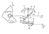
도 1a는 보는 사람의 눈에 가상 이미지를 형성하기 위한 광학적 특성 및 관계를 보여주는 개략도이다.
도 1b는 보는 사람의 눈에 가상 이미지를 형성하기 위한 광학적 특성 및 관계를 보여주는 다른 실시예에 대한 개략도이다.
도 2는 뷰어 아이 박스에 쌍안(binocular) 또는 입체적인 이미지를 형성하기 위한 디스플레이 기기를 나타내는 사시도이다.
도 3a, 3b 및 3c는 디스플레이 기기의 하나의 실시예에 대한 각각의 사시도, 측면도, 및 정면도이다.
도 4a, 4b 및 4c는 디스플레이 기기의 대안 실시예에 대한 각각의 사시도, 측면도, 및 정면도이다.
도 5a, 5b 및 5c는 디스플레이 기기의 다른 실시예에 대한 각각의 사시도, 측면도, 및 정면도이다.
도 5d는 개별 빔 스플리터 플레이트가 좌안 및 우안 가상 이미지 형성 기기 각각에 대해 사용되는 대안 실시예를 보여주는 사시도이다.
5e는 대각 각도로 배치된 빔 스플리터 플레이트를 가진 대안 실시예를 보여주는 사시도이다.
도 6a는 빔 스플리터 플레이트에서 빛을 지향시키기 위해 편광을 이용하는 대안 실시예의 개략도이다.
도 6b는 빔 스플리터 플레이트에서 빛을 지향시키기 위해 편광을 이용하는 대안 실시예의 개략도이다.
도 7은 시야의 일부가 차단된 대안 실시예의 사시도이다.
도 8a 및 8b는 본 발명의 실시예에 따른 디스플레이 기기에 대한 접힐 수 있는 패킹 배열(foldable packaging arrangement)의 측면도이다.
도 9는 보호 쉴드 및 주변 윈도우를 갖춘 기계적 하우징의 디스플레이 기기의 실시예를 나타낸다.
도 10은 보호 쉴드가 광학 시스템의 외측 및 내측 사이에 위치된, 도 9의 디스플레이 기기를 나타낸다.
도 11은 이미지 발생기를 회전시키기 위한 조정 메커니즘을 나타내는 디스플레이 기기의 단면도이다.
도 12는 디스플레이 기기의 실시예를 나타내는 것으로서, 카메라 위에 위치한 이미지 발생기의 보는 방향을 접기 위한 광학 구성요소를 가진 기계적 하우징 내에 이미지 발생기를 포함한다.
도 13은 태양 눈부심 최소화를 위한 차양을 포함하는 기계적 하우징 내의 디스플레이 기기의 실시예를 나타낸다.
도 14는 본원에 기술된 디스플레이 기기의 다른 실시예를 나타낸다.1A is a schematic diagram showing optical characteristics and relationships for forming a virtual image in a viewer's eye.
1B is a schematic diagram of another embodiment showing optical characteristics and relationships for forming a virtual image in a viewer's eye.
2 is a perspective view showing a display device for forming a binocular or stereoscopic image on a viewer eye box;
Figures 3a, 3b and 3c are respective perspective, side view, and front view, respectively, of one embodiment of a display device.
Figures 4a, 4b and 4c are respective perspective views, side views, and front views, respectively, of an alternative embodiment of the display device.
Figures 5A, 5B, and 5C are respective perspective views, side views, and front views, respectively, of another embodiment of the display device.
Figure 5d is a perspective view showing an alternative embodiment in which an individual beam splitter plate is used for each of the left and right eye virtual image forming devices.
5e are perspective views showing an alternative embodiment with beam splitter plates arranged at diagonal angles.
6A is a schematic diagram of an alternative embodiment that utilizes polarization to direct light in a beam splitter plate.
6B is a schematic diagram of an alternative embodiment that utilizes polarization to direct light in a beam splitter plate.
Figure 7 is a perspective view of an alternative embodiment in which a portion of the field of view is blocked.
8A and 8B are side views of a foldable packaging arrangement for a display device according to an embodiment of the present invention.
Figure 9 shows an embodiment of a display device of a mechanical housing with a protective shield and a peripheral window.
Figure 10 shows the display device of Figure 9, wherein a protective shield is positioned between the outside and the inside of the optical system.
11 is a cross-sectional view of a display device showing an adjustment mechanism for rotating an image generator.
Figure 12 shows an embodiment of a display device comprising an image generator in a mechanical housing with an optical component for folding the viewing direction of the image generator located above the camera.
Figure 13 shows an embodiment of a display device in a mechanical housing including an awning for minimizing sun glare.
Figure 14 shows another embodiment of the display device described herein.
본원에 도시되고 기술된 도면들은 다양한 실시예에 따른 광학 기기를 위한 작동의 주요 원리 및 제조를 나타내기 위해 제공되며, 다수의 이러한 도면들은 실제 크기 및 스케일을 보여주려는 의도로 도시되지 않았다. 작동의 원리 또는 기본적인 구조 관계를 강조하기 위해 일부 과장이 필요할 수 있다.The drawings shown and described herein are provided to illustrate the main principles and fabrication of an operation for an optical device according to various embodiments, and many of these drawings are not intended to be drawn to scale and scale. Some exaggerations may be needed to emphasize the principles of operation or basic structural relationships.
제공된 도면들은, 광학 마운트, 동력원, 이미지 데이터 소스, 및 디스플레이 장치에서 사용된 표준 사양에 대한 관련 마운팅 구조를 포함하는, 다양한 지지 구성요소를 보여주지 않을 수 있다. 본 발명의 실시예가 웨어러블 및 핸드-헬드(hand-held) 디스플레이 기기 모두로 사용되는 것들을 포함하는, 임의의 다수의 형식의 표준 마운트(standard mounts)와 지지 구성요소를 사용할 수 있음을 광학 업계의 기술자들에게 명백할 수 있다. The provided drawings may not show various supporting components, including the optical mount, the power source, the image data source, and the associated mounting structure for the standard specifications used in the display device. It will be appreciated by those of skill in the optical arts that embodiments of the present invention can use any of a number of standard mounts and support components, including those used in both wearable and hand-held display devices Can be clear to the public.
본 발명의 문맥에서, "정상" 및 "바닥" 또는 "위의" 및 "아래의" 또는 "밑의" 같은 용어들은 상대적이며 구성요소 또는 표면의 임의의 필요한 방향을 지칭하지 않지만, 시야, 대향하는 표면들, 공간 관계, 또는 구성요소 또는 기기 내의 상이한 광 경로를 간단히 나타내고 구별하는데 사용된다. 유사하게, "수평" 및 "수직"의 용어들은 표준 시야 상태에 대한 상이한 평면의 구성요소 또는 광의 상대적인 직교 관계를 설명하기 위해, 도면에 대해 사용될 수 있으며, 예를 들어, 그러나 실제 수평 및 수직 방향에 대한 구성요소의 임의의 필요한 방향을 나타내지 않을 수 있다.In the context of the present invention, terms such as "normal" and "bottom" or "above" and "below" or "under" are relative and do not refer to any necessary orientation of a component or surface, Are used to simply represent and distinguish surfaces, spatial relationships, or different optical paths within a component or device. Similarly, terms such as "horizontal" and "vertical" may be used for the figures to describe relative orthogonal relationships of components or light of different planes to a standard viewing state, Lt; RTI ID = 0.0 > a < / RTI >
"제1" 및 "제2", "제3" 등과 같은 용어가 사용되는 경우, 임의의 순서 또는 우선 관계를 반드시 나타내는 것은 아니며, 하나의 요소 또는 시간 간격을 다른 것과 더욱 명확하게 구분하기 위해 사용된다. 이들 설명은 본 발명의 내용 및 청구 범위에서 다른 유사한 요소와 하나의 요소를 명확하게 구분하기 위해 사용된다.The use of terms such as " first "and" second, "" third, " and the like, do not necessarily denote any order or priority relationship, but may be used to more clearly distinguish one element or time interval from another do. These descriptions are used to clearly distinguish one element from other similar elements in the context of the present invention and the claims.
용어 "보는 사람(viewer)", "관찰자" 및 "사용자"는 웨어러블 광학 개인 디스플레이 기기로부터 이미지를 보는 사람을 나타내기 위해 본 발명의 내용에서 상호 교환적으로 사용될 수 있다.The terms "viewer "," observer ", and "user" may be used interchangeably in the context of the present invention to indicate a person viewing an image from a wearable optical personal display device.
본원에 사용된 것처럼, "에너지 공급 가능한(energizable)"이란 용어는 동력을 받을 때 그리고, 선택적으로, 하나 이상의 가능한 신호를 수신할 때, 지정된 기능을 수행하는 장치 또는 부품의 세트에 대한 것이다. 예를 들어, 광원은 레이저 광의 빔을 방출하기 위해 에너지가 공급될 수 있으며, 이미지 데이터 신호에 따른 이미지 표현을 위해 변조될 수 있다.As used herein, the term "energizable " refers to a device or set of components that perform a specified function upon receiving power and, optionally, upon receiving one or more possible signals. For example, the light source may be energized to emit a beam of laser light and may be modulated for image representation in accordance with the image data signal.
본 발명의 내용에서, 두 평면, 방향 벡터, 또는 다른 기하학적 특성들은 그들의 실제 또는 투사된 교차점의 각도가 90도의 ±4도 내에 있을 때 실질적으로 직교하는 것으로 간주된다.In the context of the present invention, two planes, direction vectors, or other geometric features are considered to be substantially orthogonal when their actual or projected intersection point angles are within +/- 4 degrees of 90 degrees.
본 발명의 내용에서, "경사진"이란 용어 또는 "경사각(oblique angle)"이란 문구는 수직과 다른 비스듬한 비-수직, 즉, 적어도 하나의 축을 따라 적어도 약 4도 또는 그 이상까지, 90도 또는 90도의 정수배가 아닌 것을 의미하는데 사용된다. 예를 들어, 사각은 이러한 일반적인 정의를 이용하여 90도보다 적어도 약 4도 더 크거나 또는 더 작을 수 있다. In the context of the present invention, the term " inclined "or the term" oblique angle "refers to an oblique non-perpendicular to vertical, i.e., at least about 4 degrees or more along at least one axis, Which is not an integer multiple of 90 degrees. For example, a square may be at least about four degrees greater or less than 90 degrees using this general definition.
본 발명의 문맥에서, "연결된"이란 용어는 두 개 이상의 구성요소 사이의 기계적 연합, 연결, 관계, 또는 이음을 지칭하는 것이므로, 하나의 구성요소의 배치는 그것이 연결되는 구성요소의 공간적 배치에 영향을 미친다. 기계적 연결을 위해, 두 개의 구성요소는 직접적인 연결만이 아니라, 하나 이상의 중간 구성요소를 통해 연결될 수 있다.In the context of the present invention, the term "connected" refers to a mechanical association, connection, relationship, or coupling between two or more elements, so that the placement of one element affects the spatial arrangement of the elements to which it is connected . For mechanical connection, the two components can be connected via one or more intermediate components, not just the direct connection.
본 발명의 문맥에서, "좌안 이미지(left eye image)"란 용어는 보는 사람의 좌측 눈에 보여지는 가상의 이미지를 나타내며, "우안 이미지(right eye image)"란 용어는 보는 사람의 우측 눈에 보여지는 상응하는 가상 이미지를 나타낸다. "좌안" 및 "우안"이란 용어는 입체 이미지화 분야의 당업자들에게 널리 이해되고 있는 표현으로서, 입체 이미지 쌍의 각각의 이미지를 형성하기 위해 이미지화 구성요소들을 구별하기 위한 형용사로서 사용될 수 있다. In the context of the present invention, the term "left eye image" refers to a hypothetical image seen in the left eye of a viewer and the term "right eye image " Represents the corresponding virtual image shown. The terms "left eye" and "right eye" are widely understood expressions of skill in the art of stereoscopic imaging and may be used as adjectives to distinguish imaging components to form each image of a stereoscopic image pair.
"적어도 하나"라는 용어는 나열된 아이템들 중 하나 이상이 선택된 것을 의미하는데 사용된다. "약" 또는 "대략"이란 용어는, 치수 측정 또는 배치에 대해 참조로 사용될 때, 실제로 허용되는 측정 에러 및 부정확에 대한 예상 공차 내에 있는 것을 의미한다. 나열된 표현된 값은, 공칭 값으로부터의 편차가 예시된 실시예에 대한 요구에 순응하기 위해 공정 또는 구조의 실패를 야기하지 않는 한, 공칭 값에서 다소 변경될 수 있다. The term "at least one" is used to mean that one or more of the listed items is selected. The terms "about" or "about " when used as a reference for dimension measurement or placement, are meant to be within the expected tolerance for measurement errors and inaccuracies that are actually allowed. The listed values listed may vary slightly from the nominal values, unless deviations from the nominal values cause failure of the process or structure to comply with the requirements for the illustrated embodiment.
치수에 대해, "실질적으로"라는 용어는 기하학적으로 정확한 치수의 ±12%보다 나은 범위 내를 의미한다. 따라서, 예를 들어, 제1 치수 값은 제2 값의 약 44% 내지 약 56%의 범위에 있는 경우, 제2 값의 실질적으로 절반이다. 공간 상의 배치는, 곡률 반경, 초점, 구성요소 위치, 또는 광학 축 상의 다른 지점과 같은 적절한 참조 치수에 대해, 거리 치수가 실질적으로 같거나, 약 12% 이상 떨어져 있지 않거나, 바람직하게 서로 5% 또는 1% 또는 그 이하 내의 거리에 있을 때, 서로 "근처"에 있거나 또는 아주 근접해 있다.For dimensions, the term "substantially" means within a range that is better than +/- 12% of the geometrically correct dimension. Thus, for example, the first dimension value is substantially half of the second value when in the range of about 44% to about 56% of the second value. The spatial arrangement may be such that, for appropriate reference dimensions, such as radius of curvature, focus, component location, or other point on the optical axis, the distance dimensions are substantially the same, no more than about 12% They are "near" or very close to each other when they are at a distance of 1% or less.
"작동 가능한(actuable)"라는 용어는 예컨대 전기 신호에 대한 것과 같이, 자극에 대응하여 작동을 야기할 수 있는 장치 또는 구성요소와 관련한, 종래의 의미를 갖는다.The term "actuable" has its conventional meaning in relation to a device or component that can cause operation in response to a stimulus, such as for an electrical signal.
본 출원에서 사용된 "신호 통신"이라는 용어는 둘 이상의 장치 및/또는 구성요소가 어떤 형식의 신호 경로를 통해 전달되는 신호를 통해 서로 통신할 수 있는 것을 의미한다. 신호 통신은 유선 또는 무선일 수 있다. 신호는 제1 장치 및/또는 구성요소로부터 제2 장치 및/또는 구성요소로 상기 제1 장치 및/또는 구성요소와 제2 장치 및/또는 구성요소 사이의 신호 경로를 따라 정보, 동력, 및/또는 에너지를 연통할 수 있는 통신, 동력, 데이터, 또는 에너지 신호일 수 있다. 신호 경로는 제1 장치 및/또는 구성요소와 제2 장치 및/또는 구성요소 사이의 물리적, 전기적, 자기적, 전자기적, 광학적, 유선, 및/또는 무선 연결을 포함할 수 있다. 신호 경로는 또한 제1 장치 및/또는 구성요소와 제2 장치 및/또는 구성요소 사이의 추가 장치 및/또는 구성요소를 포함할 수 있다.The term "signal communication ", as used herein, means that two or more devices and / or components can communicate with each other through a signal carried over a signal path of some type. The signaling communication can be wired or wireless. The signal may be information, power, and / or information along the signal path between the first device and / or the component and the second device and / or component from the first device and / or component to the second device and / Or communication, power, data, or energy signal that can communicate energy. The signal path may include physical, electrical, magnetic, electromagnetic, optical, wired, and / or wireless connections between the first device and / or component and the second device and / or component. The signal path may also include additional devices and / or components between the first device and / or the component and the second device and / or component.
"예시의"라는 용어는 설명이 이상적인 것을 암시하는 것보다 예시로서 사용됨을 나타낸다.The word "exemplary" indicates that the description is used as an example rather than an imply an ideal.
광학 기기의 구성 요소 또는 곡률 중심 또는 다른 특징과 관련하여, "근사"라는 용어는 예상되는 제조 허용 오차 및 측정 부정확과 더불어 예를 들어, 빛의 이론과 실제의 거동 사이의 예상되는 차이점을 고려하여, 광학 디자인 분야의 기술자에 의해 사용되는 것과 같은 일반적인 함축적 의미를 갖는다.With respect to components or curvature centers or other features of an optical instrument, the term "approximate" is to be construed as taking into account the expected manufacturing tolerances and measurement inaccuracies as well as the expected differences between, for example, , Which has the general implication of being used by an engineer in the field of optical design.
공지된 바와 같이, 특정 광학 시스템 내 및 특정 광학 시스템으로부터의 광 분포는 그것의 전체 구성에 의존하며, 적절한 성능을 위해 기하학적으로 완전하거나 또는 이상적인 대칭을 나타낼 필요가 없다. 예를 들어, 곡면 거울에 대한 광 분포는 초점을 중심으로 실질적으로 중심에 있는 작은 영역에 초점을 맞추는 것으로보다 정확하게 설명될 수 있다. 그러나, 설명의 목적을 위해, "초점" 또는 "초점 영역"과 같은 종래의 용어가 사용된다. "아이 박스(eye box)"라는 용어는 광학 시스템에 의해 형성된 가상 이미지를 볼 수 있는 영역을 나타낸다.As is known, the light distribution within and in a particular optical system depends on its overall configuration and does not need to exhibit a geometrically perfect or ideal symmetry for proper performance. For example, the light distribution for a curved mirror can be more accurately described as focusing on a small area substantially centered about the focal point. However, for purposes of explanation, conventional terms such as "focus" or "focus area" The term "eye box" refers to an area in which a virtual image formed by the optical system can be viewed.
단일 위치에서 장면이 보여지고 양 눈 위치에서 관찰자에게 표시될 때, 보기는 깊이, 3차원 효과의 인식이 부족하다. 이러한 방식으로 보여진 장면을 양안(bi-ocular)이라고 한다. 그러나, 단일 장면을 서로 약간 떨어진 두 위치에서 보면, 관찰자에게 보여지는 보기에 깊이 감이 있다. 이런 식으로 보이는 장면을 쌍안(binocular)이라고 한다. 하나의 위치에서 보았을 때 하나의 위치에서 생성된 장면을 단안(monocular)이라고 하며 이는 3차원 효과가 없다.When a scene is viewed from a single location and is displayed to an observer at both eye positions, the view lacks depth and depth awareness of the 3D effect. The scene shown in this way is called bi-ocular. However, if you look at a single scene from two positions slightly apart from each other, there is a depth in the view shown to the observer. The scene that looks like this is called a binocular. When viewed from a single location, the scene created at one location is called a monocular, which has no 3D effect.
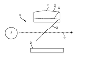
이미징 분야의 기술자에게 공지된 바와 같이, 가상 이미지는 광학 시스템으로부터 눈에 제공되고 아이 박스의 공간에서 보여지는 광선의 분기에 의해 종합적으로 시뮬레이션된다. 광학 시스템은 주어진 위치와 거리에서 보는 사람의 시야에 나타나는 가상 이미지를 형성한다. 그로부터 광선이 실제로 분기되는 시야에는 상응하는 "실제" 물체가 없다. "증강 현실(augmented reality)"로 불리는 보는 시스템은 가상 이미징 시스템을 채용하여 보는 사람의 시선을 따라 보이는 실제 현실 세계의 물체 장면 상에 가상 이미지의 중첩을 제공한다. 보는 사람의 시야에 물체 장면 이미지 콘텐츠와 결합된 가상 이미지를 형성하는 이러한 능력은 보는 사람에게 실제 이미지만을 제공하는 다른 디스플레이 장치와 증강 현실 이미징 장치를 구별한다. As is known to those skilled in the imaging arts, a virtual image is comprehensively simulated by the divergence of the rays provided to the eye from the optical system and viewed in the space of the eye box. The optical system forms a virtual image that appears in the viewer's field of view at a given location and distance. There is no corresponding "real" object in the field from which the rays actually diverge. A viewing system called "augmented reality " employs a virtual imaging system to provide superimposition of virtual images on real-world object scenes that follow the viewer's gaze. This ability to form a virtual image combined with object scene image content in the view of the viewer distinguishes the augmented reality imaging device from other display devices that only provide the viewer with an actual image.
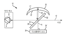
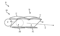
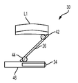
도 1a의 개략도를 참고하면, 아이 박스(E)의 눈 동공(P)으로 보기 위한 가상 이미지를 형성하는 가상 이미지 형성 기기(10)가 측면으로 도시되어 있다. 제1 및 제2 평행 표면(S1, S2)을 가진 빔 스플리터 플레이트(26)(대안으로, 플레이트 빔스플리터, 빔스플리터, 또는 빔 스플리터로 칭함)는 시선(12)을 따라 비스듬히 배치되고 이미지를 제공하기 위한 이미지 발생기(24)와 렌즈(L1) 사이의 자유 공간에 배치된다. 도시된 실시예에서, 이미지 발생기(24)는 이미지를 제공하기 위한 디스플레이 표면(24')을 가진 디스플레이 소스이다. 일부 실시예에서, 도 1에 도시된 바와 같이, 이미지 발생기의 표면(24')은 평평하므로 이미지를 포함하는 빛의 평평한 필드를 발생한다. 예를 들어, 디스플레이 표면은 휴대폰 또는 "스마트폰"의 평평한 디스플레이 표면일 수 있다. 그러나, 다른 실시예에서, 이미지 발생기(24)의 디스플레이 표면(24')은 약간 만곡될 수 있다.1A, there is shown a side view of a virtual
도 1a는 이러한 실시예에서 렌즈(L1)가 수정된 반월판(meniscus)인 것으로 도시된다. 더욱 구체적으로, 렌즈(L1)는 이미지 발생기(24)에 대해 오목한 굴절 비구면 표면(22)과 이미지 발생기(24)에 대해 또한 오목한 반사 비구면 표면(20)을 갖는다. 도 1a 실시예에서, 렌즈(L1)는 반사 굴절 광학 요소 - 즉, 평평한 이미지 필드(즉, 시야를 가로지르는 평평한 이미지 표면)에서의 구면 수차 없이 이미지 발생기(24)로 다시 빛을 반사시키는 만곡된 거울을 형성하는 요소의 후방에 반사 표면을 가진 반월판 렌즈일 수 있다. 반사 비구면 표면(20)의 주축(A)은 이미지 발생기(24)에 수직한다. 이미지 발생기(24)는 빔 스플리터 플레이트(26)의 이격된 표면(S2)을 향해 이미지를 포함하는 빛의 평평한 필드를 지향시키도록 에너지가 공급될 수 있다. 이미지 발생기(24), 빔 스플리터 플레이트(26), 및 렌즈(L1)는 협력하며 아이 박스(E)에서 시선(12)을 따라 보여질 수 있는 가상 이미지를 형성하도록 구성된다. 일부 실시예에서, 이미지 발생기(24)는 보는 사람의 눈 위에 위치될 수 있고, 렌즈는 보는 사람의 눈 아래에 위치될 수 있다. 일부 실시예에서, 이미지 발생기(24)는 보는 사람의 눈 아래에 위치될 수 있고, 렌즈(L1)는 보는 사람의 눈 위에 위치된다.Figure 1A shows the lens L1 in this embodiment as being a modified meniscus. More specifically, the lens L1 has a concave refracting
빔 스플리터 플레이트(26) 및 렌즈(L1)는, 하나의 눈에 대한 이미지를 위해, 광 경로(40)를 형성하며, 그 경로를 따라 빔 스플리터 플레이트(26)로부터의 빛은 비구면 입사 굴절 표면(22)을 통해 제1 방향으로 제1 굴절을 위해 자유 공간을 통과하여 전송된다. 굴절된 빛은 비구면 반사 표면(20)으로부터 반사되며 이후 광 경로(40)를 따라 다시 이어지며, 상기 반사된 빛은 비구면 입사 굴절 표면(22)으로부터 다시 한번 굴절된다. 빛은 이후 자유 공간을 통과해 보는 사람의 시선(12)을 따라 뷰어 아이 박스(E)를 향해 방해받지 않는 경로를 따라 렌즈(L1)로부터 빛을 반사시키는 빔 스플리터 플레이트(26)로 다시 돌아가며, 물체 장면에 대한 시선(12)은 빔 스플리터 플레이트(26)를 통해 연장된다. 빔 스플리터 플레이트(26)는 비스듬한 윈도우를 제공하며 그를 통해 물체 장면이 보여질 수 있다. 따라서, 빔 스플리터는 이미지 발생기로 발생된 이미지를 포함하는 빛이 렌즈를 향해 전파할 때 빔 스플리터를 횡단하고, 렌즈에 의해 반사된 이후 빔 스플리터로부터 반사되도록 구성되고 위치된다. 일부 실시예에 따라, 빔 스플리터 플레이트(26)는 25 grams보다 작은 무게를 가지며(예, <20 grams, <15 grams, <10 grams), 적어도 30 도(degree)인 수평 전체 시야(a horizontal full field of view)를 제공하고, 일부 실시예에서는 40 도(예, 40 - 70 도, 예를 들어 50 - 60 도)를 초과한다. 일부 실시예에서, 빔 스플리터 플레이트(26)는 2 - 10 grams의 무게를 가지며, 예를 들어, 5 grams을 넘지 않고, 일부 실시예에서, 2 내지 5 grams의 무게를 갖는다. 일부 실시예에 따라서, 빔 스플리터 플레이트(26)는 부분 반사 표면을 가지며, 상기 부분 반사 표면은 렌즈(L1, L2)을 향해 위치된다. 본원에 기술된 예시의 실시예에서, 부분 반사 표면은 가시 스펙트럼에서 투과하는 빛의 적어도 25 %(예, 25 % 내지 75 %, 또는 30 % 내지 70%, 또는 40 내지 60 % 또는 45 내지 65 %)를 반사하고, 가시 스펙트럼에서 투과하는 빛의 적어도 25 %(예, 25 % 내지 75 %, 또는 30 % 내지 70%, 또는 40 내지 60 % 또는 45 내지 65 %)를 투과시킨다. 예를 들어, 부분 반사 표면은 가시 스펙트럼에서의 (i) 빛의 45 %를 투과하고 빛의 55 %를 반사하거나, 또는 (ii) 빛의 50 %를 투과시키고, 빛의 50 %를 다시 반사시키거나, 또는 (iii) 빛의 55 %를 투과시키고 45 %를 반사시킬 수 있다.The
이미징 광학 요소가 (이미지 발생기(24)를 향해 있는 굴절 표면과 반사 후면 표면을 가진) 렌즈(L1) 대신, 단순히 구형 거울이었다면, 결과적인 필드는 매우 초점이 않맞을 것이다. 이러한 초점 이탈은 시야를 충분히 감소시킴으로써 해결될 수 있다. 그러나, 본원에 기술된 실시예에 의해 도시된 것과 같이, 굴절과 더불어 반사시키는 렌즈 표면을 가진 광학 구성요소(L1, L2)를 가짐으로써, (동공 및 필드를 가로지르는)이미지 수차를 보정할 수 있으며 시야가 40 도를 초과하는 경우에도 초점이 잘 맞는 이미지를 얻을 수 있다. 이미지 발생기(24)로부터의 빛은 굴절 표면(22)을 통해 두번 지나가기 때문에, 렌즈(L1)는 3개의 비구면 표면과 동등한 효과를 제공하며, 단순하고, 단일의, 컴팩트한, 경량의 요소를 통해 40 도를 초과하는 넓은 시야 이상의 몇몇 광학 수차를 보정할 수 있다. 일부 실시예에서, 하나 이상의 비구면 표면은 비구면 표면의 광학적 성질을 형성하는 곡률 반경, 원뿔 상수(conic constants), 또는 다른 요인(예, 하기에 더 자세하게 설명될 A, B, 및 C 비구면 계수)과 같은 상이한 요인들을 가질 수 있다. 일부 실시예에서, 모든 비구면 표면은 이러한 상이한 곡률 반경 및/또는 다른 요인을 가질 수 있다. If the imaging optical element was simply a spherical mirror instead of the lens L1 (having a refractive surface and a reflective rear surface facing the image generator 24), then the resulting field would be very out of focus. Such defocusing can be overcome by sufficiently reducing the field of view. However, by having optical components L1, L2 with a lens surface that reflects with refraction, as illustrated by the embodiments described herein, it is possible to compensate for image aberration (across pupil and field) And even if the field of view exceeds 40 degrees, you can get a well-focused image. Since the light from the
본원에 나타낸 것처럼, "평평한 이미지 필드"는 시야를 가로지르는 평평한 이미지 평면을 나타낸다. 본원에 나타낸 것처럼, 이미지 발생기(24)에 의해 발생된 "이미지의 평평한 필드" 및 "이미지를 포함하는 빛의 평평한 필드"는 평평한 디스플레이 표면(24') 또는 소스(24)에 의해 디스플레이된 (물체)시야를 가로질러 이 표면으로부터 나오는 빛을 나타낸다.As shown herein, a "flat image field" represents a flat image plane across the field of view. As described herein, the "flat field of image" and "flat field of light containing image" generated by
본 발명의 실시예에 따라, 렌즈(L1)는 가상 이미지의 필드 곡률에 대한 보정을 제공하도록 디자인된다. 다른 실시예에서, 필드 곡률을 보상하기 위한 대안 접근법은 이미지 발생기(24) 가까이에 배치된 필드 렌즈를 사용하는 것이다; 그러나, 광학 경로(40)를 따른 반사 표면에서의 모놀리식 렌즈(monolithic lens)의 사용은 동일한 기능을 제공할 수 있고 광학적 배치 요구를 감소시키고 크기 및 종횡비가 다를 수 있는 디스플레이를 포함하여, 임의의 수의 형식의 디스플레이가 사용될 수 있게 하는 단순화에 대한 이점이 있다.According to an embodiment of the present invention, the lens L1 is designed to provide correction for the field curvature of the virtual image. In another embodiment, an alternative approach to compensate for the field curvature is to use a field lens disposed near the
이미지 뒤틀림은 대안으로 광학 시스템의 하나 이상의 추가 렌즈(L1', L2')(도시되지 않음)를 이용하여 보정될 수 있다. 그러나, 뒤틀림은 또한 이미지 데이터에 대한 적절한 조정을 통해, 간단하게 디지털 방식으로 보정될 수도 있다. Image distortion may alternatively be corrected using one or more additional lenses L1 ', L2' (not shown) of the optical system. However, the distortion may also be corrected in a simple digital manner, with appropriate adjustment to the image data.
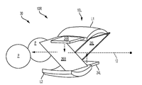
도 1a는 단일의 좌안 또는 우안 이미지를 형성하기 위한 가상 이미지 형성 기기(10)의 구성요소의 배열을 보여준다. 도 2의 개략도는 디스플레이 기기(30)가 단일 빔 스플리터 플레이트(26)를 이용하는 각각의 아이 박스(EL, ER)에서 보여질 수 있는 좌안 및 우안 이미지를 통해, 쌍안의 가상 이미지를 형성하는 방법을 나타낸다. 단일 이미지 발생기(24)는 각각, 실제 좌안 및 우안 이미지(32L. 32R)를 생성한다. 좌안 이미지(32L)로부터의 이미지를 포함하는 빛의 평평한 필드는 빔 스플리터 플레이트(26)를 통해 렌즈(L1)로 전달된다. 이러한 배열을 통해, 이미지 발생기(24) 및 렌즈(L1)는 빔 스플리터 플레이트(26)와 협력하는 좌안 가상 이미지 성형 기기(10L)를 형성한다. 유사하게, 우안 이미지(32R)로부터의 빛은 빔 스플리터 플레이트(26)를 통해 그리고 렌즈(L2)로 전송된다. 이미지 발생기(24) 및 렌즈(L2)는 빔 스플리터 플레이트(26)를 통해 우안 가상 이미지 형성 기기(10R)를 형성한다. 좌안 및 우안 가상 이미지 모두를 위해 아이 박스 위치를 정하기 위한 단일 빔 스플리터 플레이트(26)와 렌즈(L1, L2)의 사용은 부품 수를 감소시키고 구성요소 장착을 단순하게 하는데 유리하다. 도 2의 배열은 적절한 좌안 및 우안 이미지 콘텐츠가 제공될 때 입체적으로 보일 수 있다. 게다가, 예를 들어, 이미지 발생기와 빔 스플리터 플레이트(26) 사이에 필드 렌즈가 추가되어 수차에 대해 추가로 보정할 수 있다. 예를 들어, 필드 렌즈는 이미지 발생기에 인접하게 위치될 수 있다.1A shows an arrangement of components of a virtual
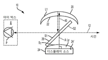
일부 실시예에서(예를 들어, 도 1b 참조), 렌즈(L1, L2) 중 오직 하나의 표면(렌즈(L1, L2)의 반사 또는 굴절 표면 중 하나)은 비구면이다. 도 1b의 실시예는 도 1에 도시된 실시예와 유사하며, 그러나 이미지 발생기에 인접하여 또는 접촉하여 위치한 필드 렌즈(LF)를 더 포함한다. 도 1b의 실시예에서, 필드 렌즈(LF)는 적어도 하나의 비구면 표면, 예를 들어, 표면(S1)을 갖는다.In some embodiments (see, for example, FIG. 1B), only one of the lenses L1, L2 (one of the reflective or refractive surfaces of the lenses L1, L2) is aspherical. The embodiment of FIG. 1B is similar to the embodiment shown in FIG. 1, but further includes a field lens (L F ) located adjacent to or in contact with the image generator. In the embodiment of FIG. 1B, the field lens L F has at least one aspherical surface, for example,
도 2의 디스플레이 기기(30)의 디자인은 각각의 렌즈(L1, L2)의 초점 길이에 따라 스케일될 수 있다. 도 3a 내지 5d는 상이한 초점 길이가 가능한 상이한 예시의 배열이 도시되며, 이는 초점 길이에 기초하여 더 길거나 더 짧은 눈동자 거리(eye relief)를 허용한다. 게다가, 디스플레이 기기(30) 구성요소의 수직 간격은 다소 컴팩트할 수 있으며, 디스플레이 기기가 다수의 웨어러블 및 헤드-장착 구성과 더불어 핸드-헬드 구성을 위해, 또는 디스플레이 기기(30)가 다른 장비에 장착되는 고정 구성을 위해 크기가 조정(scale)될 수 있다. The design of the
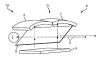
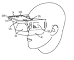
도 3a는 디스플레이 기기(30)의 구성의 전방 사시도로서, 디스플레이 표면의 상이한 부분으로부터, 각각의 상응하는 아이 박스에서 각각의 동공(P)(보는 사람의 눈 동공)으로, 좌안 및 우안 이미지 콘텐츠를 제공하기 위한 단일 이미지 발생기(24)를 포함한다. 도 3b는 도 3a 구성의 측면도를 나타낸다. 도 3c는 도 3a 구성의 정면도이다. 도 3c의 전방 평면도에 나타난 것처럼, 각각의 눈의 시야는 수평으로 비대칭일 수 있다. 즉, 눈의 외부에 대한 시야, 즉, 우측 및 좌측에 대해 수평으로 연장된 주변 필드는 눈의 내부에 대한 시야보다 더 클 수 있다.Figure 3a is a front perspective view of the configuration of the
도 3a 및 다음 실시예에서, 상응하는 좌측 또는 우측 눈에 대한 상응하는 좌측 또는 우측 시선(12)이 존재한다.In Fig. 3A and the following embodiments, there is a corresponding left or
각각 개별적인 좌안 및 우안 이미지 발생기(24L, 24R)을 사용하는 실시예에 대해 도 4a는 사시도로 나타내고, 도 4b는 측면도, 도 4c는 평면도로 나타낸다. 이미지 발생기(24L, 24R) 및/또는 디스플레이 표면(24L', 24R')은 동일한 평면에 놓일 수 있으며 또는 서로 오프셋될 수 있으며, 개선된 패키징을 위해 틸트(tilt)되거나 조정될 수 있으며, 또는, 예를 들어, 보는 사람의 인체 구조에 대해 조정될 수 있다.FIG. 4A is a perspective view, FIG. 4B is a side view, and FIG. 4C is a plan view for an embodiment using the left and right
단일 빔 스플리터 플레이트(26)와 개별 좌안 및 우안 이미지 발생기(24L, 24R)를 각각 사용하는 대안 실시예에 대해 도 5a는 사시도로 나타내고, 도 5b는 측면도, 도 5c는 정면도로 나타낸다. 5A is a perspective view, FIG. 5B is a side view, and FIG. 5C is a front view, respectively, for an alternative embodiment using a single
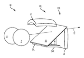
도 5d는 대안 실시예를 나타내는 사시도로서, 개별 빔 스플리터 플레이트(26L)가 좌안 가상 이미지 형성 기기(10L)에 대해 사용되고; 빔 스플리터 플레이트(26R)가 우안 가상 이미지 형성 기기(10R)에 사용된다. 각각의 빔 스플리터 플레이트(26L, 26R)는 상응하는 좌안 또는 우안에 대해 상응하는 좌측 또는 우측 시선(12)을 따라 놓인다. 5D is a perspective view showing an alternative embodiment, in which an individual
도 5e의 사시도는 좌안 및 우안 가상 이미지 형성 기기를 위한 개별 빔 스플리터 플레이트(26L, 26R)를 이용하는 대안 실시예를 나타낸다. 좌측 및 우측 빔 스플리터 플레이트(26L, 26R)는 시선(12)에 대해 대향하며 비스듬한 각도로 배치된다. 렌즈(L1, L2)의 이미지 발생기(24L, 24R)의 위치는 또한 가상 이미지 형성 기기(10L, 10R) 사이에서 반전된다. 좌안 및 우안 이미지 발생기(24L, 24R) 각각은 반대 방향으로 이미지를 포함하는 빛을 지향시킨다. 이러한 대안 배열은 예를 들어, 더욱 콤팩트한 패키징을 제공하기 위해 유용할 수 있다.The perspective view of Figure 5e shows an alternative embodiment using separate
도 5a-5e의 실시예는, 예를 들어, OLED 기반 이미지 발생 장치로 활용될 수 있다. 하나의 실시예에서, 이러한 OLED 기반 이미지 발생 장치는 44 microns x 44 microns, 40 microns x 40 microns, 30 microns x 30 microns, 24 microns x 24 microns, 20 microns x 20 microns 이상의 픽셀을 가지며, 또는 이미지 발생 장치는 더 작은 크기의 픽셀도 가질 수 있다. 다른 이미지 발생 장치가 또한 활용될 수 있다.The embodiment of Figures 5A-5E may be utilized, for example, as an OLED based image generating device. In one embodiment, such an OLED based image generating device has pixels of 44 microns x 44 microns, 40 microns x 40 microns, 30 microns x 30 microns, 24 microns x 24 microns, 20 microns x 20 microns, The device can also have pixels of smaller size. Other image generating devices may also be utilized.
일부 실시예에 따라, 디스플레이 기기는 광학 시스템을 포함한다. 상기 광학 시스템은: (i) 이미지 발생기 디스플레이 표면으로부터 이미지를 포함하는 빛을 발생하는 이미지 발생기; (ii) 상기 이미지 발생기로부터 이격된 적어도 두 개의 렌즈, 여기서, 상기 두 개의 렌즈 각각은 이미지 발생기에 대해 오목한 입사 굴절 표면 및 이미지 발생기에 대해 오목한 반사 표면을 가지며, 상기 반사 또는 굴절 표면 중 적어도 하나는 비구면 표면임; 및 (iii) 상기 이미지 발생기와 렌즈 사이의 자유 공간에 배치되고, 보는 사람의 시선에 비스듬한 제1 및 제2 표면을 가진 빔 스플리터 플레이트;를 포함하고,According to some embodiments, the display device includes an optical system. The optical system comprising: (i) an image generator for generating light comprising an image from a display surface; (ii) at least two lenses spaced from the image generator, wherein each of the two lenses has a concave incident refracting surface with respect to the image generator and a concave reflecting surface with respect to the image generator, at least one of the refracting or refracting surfaces Aspheric surface; And (iii) a beam splitter plate disposed in the free space between the image generator and the lens, the beam splitter plate having first and second surfaces tilted to the line of sight of the viewer,
상기 렌즈 및 빔 스플리터 플레이트는 보는 사람의 시선을 따라 이미지를 포함하는 빛을 위한 뷰어 아이 박스를 형성한다. The lens and beam splitter plate form a viewer eye box for light including an image along the line of sight of the viewer.
본원에 개시된 디스플레이 디자인은 8 mm 내지 40 mm(예, 10 mm 내지 30 mm) 사이의 눈동자 거리(즉, 눈 동공과 빔 스플리터의 가장 가까운 에지 사이의 수평 거리), 30 도 내지 70 도(예, 40 도 내지 70 도) 사이의 수평 FOV, 및 1 min/pixel 내지 4 min/pixel 사이의 해상도를 야기할 수 있다. 약 1 min/pixel의 해상도는, 예를 들어, 20 x 20 μm 픽셀을 가진 OLED 디스플레이와 같은 이미지 발생기를 사용하는 경우, 성취될 수 있다. 일부 실시예에 따라, 렌즈(L1, L2)의 반사 및 굴절 표면은 상기 렌즈의 광학축이 1 각분(minute of arc) 내에서 서로 평행하고 50 mm 내지 80 mm (예, 60-70mm) 사이의 거리에 의해 서로 이격되도록 구성된다. 디스플레이 기기의 광학 시스템은 Dp ≥ 7 mm, 예를 들어, 7 mm ≤ Dp ≤ 20 mm (예, 8 mm, 10 mm, 12 mm, 15 mm, 18 mm, 20 mm, 또는 그 사이)의 지름을 가진 출사동(exit pupil)을 더욱 포함한다. The display designs disclosed herein may have a pupil distance between 8 mm and 40 mm (e.g., 10 mm to 30 mm) (i.e., a horizontal distance between the eye pupil and the nearest edge of the beam splitter), a 30 to 70 degree A horizontal FOV of between 40 and 70 degrees, and a resolution of between 1 min / pixel and 4 min / pixel. Resolution of about 1 min / pixel can be achieved, for example, when using an image generator such as an OLED display with 20 x 20 μm pixels. According to some embodiments, the reflective and refractive surfaces of the lenses L1, L2 are arranged such that the optical axis of the lenses is parallel to one another within a minute of arc and between 50 mm and 80 mm (e.g., 60-70 mm) Are spaced apart from each other by a distance. The optical system of the display device has a diameter of Dp ≥ 7 mm, for example 7 mm ≤ Dp ≤ 20 mm (eg 8 mm, 10 mm, 12 mm, 15 mm, 18 mm, 20 mm, And further includes an exit pupil.
일부 실시예에 따라, 광학 시스템은 Dp ≥ 7 mm의 출사동 지름을 가진 출사동을 더욱 포함하며, 또한 수직 시야에 대한 수평 시야의 비율이 FOVh/FOVv > 1.5이 되도록 수직 전체 시야(FOVv) 및 수평 전체 시야(FOVh)를 갖는다. 일부 실시예에서, FOVh/FOVv > 1.7, 예를 들어, 3 ≥ FOVh/FOVv > 1.7이다. According to some embodiments, the optical system further includes an exit pupil having an exit pupil diameter of Dp ≥ 7 mm, and further includes a vertical full field of view (FOVv) such that the ratio of horizontal field of view to vertical field is FOVh / FOVv> 1.5 And has a horizontal total visual field FOVh. In some embodiments, FOVh / FOVv > 1.7, e.g., 3 > FOVh / FOVv > 1.7.
일부 실시예에 따라, 이미지 발생기(24)와 렌즈(L1, L2) 사이의 거리는 20 - 60 mm, 예를 들어, 30 - 50 mm이다.According to some embodiments, the distance between the
일부 실시예에 따라, 디스플레이 기기는:According to some embodiments, the display device comprises:
(i) 이미지 발생기 디스플레이 표면으로부터 이미지를 포함하는 빛을 발생하는 이미지 발생기; (ii) 이미지 발생기에서 이격된 렌즈, 여기서, 상기 렌즈는 이미지 발생기에 대해 오목한 입사 굴절 표면을 가지며 이미지 발생기에 오목한 반사 표면을 가지고, 상기 표면 중 적어도 하나는 비구면임; 및 (iii) 상기 이미지 발생기와 렌즈 사이의 자유 공간에 배치되고 보는 사람의 시선에 비스듬한 제1 및 제2 표면을 가진 빔 스플리터 플레이트;를 포함하고, 여기서, 상기 렌즈 및 빔 스플리터 플레이트는 보는 사람의 시선을 따른 이미지를 포함하는 빛을 위한 뷰어 아이 박스를 형성하며, 여기서 상기 디스플레이 기기는: (a) 30 내지 70 도 사이의 수평 시야, 5 mm 내지 50 mm 사이의 눈동자 거리, 30 mm 내지 70 mm 사이의 렌즈의 초점 거리; 7 mm 내지 20 mm 사이의 출사동 지름, 30 mm 내지 70 mm의 렌즈와 디스플레이 사이의 거리; 또는 (b) 5 mm 내지 40 mm 사이의 눈동자 거리, 30 내지 70 도 사이의 수평 FOV, 1 min/pixel 내지 4 min/pixel 사이의 해상도; 중 적어도 하나를 나타낸다. 일부 실시예에 따라, 디스플레이 기기는 44 micrometers보다 작은 측면 색수차(lateral chromatic aberration)를 나타낸다(측면 컬러는 컬러(적, 녹, 청(R, G, B)를 이용한 배율의 변화이다). 일부 실시예에 따라, 디스플레이 기기는 픽셀의 크기보다 작은 - 즉, R, G, B 광선이 동일한 픽셀 내에 있도록 측면 색수차를 나타낸다. 일부 실시예에 따라, 디스플레이 기기는 이미지 발생기의 픽셀 크기보다 더 크지 않은 측면 색수차를 나타낸다.(i) an image generator for generating light including an image from an image generator display surface; (ii) a lens spaced from the image generator, wherein the lens has a concave incident refracting surface with respect to the image generator and has a concave reflecting surface in the image generator, at least one of the surfaces being aspherical; And (iii) a beam splitter plate disposed in the free space between the image generator and the lens, the beam splitter plate having first and second surfaces oblique to the line of sight of the viewer, wherein the lens and beam splitter plate Wherein the display device comprises: (a) a horizontal field of view between 30 and 70 degrees, a pupil distance between 5 and 50 mm, a distance between 30 and 70 mm The focal length of the lens between; An emergent copper diameter of between 7 mm and 20 mm, a distance between the lens and the display of between 30 mm and 70 mm; Or (b) a pupil distance between 5 mm and 40 mm, a horizontal FOV between 30 and 70 degrees, a resolution between 1 min / pixel and 4 min / pixel; ≪ / RTI > According to some embodiments, the display device exhibits lateral chromatic aberration less than 44 micrometers. (The side color is a change in magnification using color (red, green, blue (R, G, B) By way of example, the display device exhibits lateral chromatic aberrations such that the R, G, B rays are less than the size of the pixel - that is, within the same pixel. According to some embodiments, Chromatic aberration.
하기 표(표 1)는 도 3a-5c에 도시된 여러 가지 예시의 실시예에 대한 다양한 성능 특성을 나열한다.The following table (Table 1) lists various performance characteristics for the various example embodiments shown in Figures 3A-5C.
각 (H x W) FOV
Each (H x W)
릴리프
(Eye relief)children
Relief
(Eye relief)
(주 1)Resolution
(Note 1)
주 1: - 표 1의 처음 3개의 실시예의 각 해상도 값은 0.044 mm 디스플레이 픽셀을 가진 상업적으로 이용할 수 있는 스마트폰에 기반한 것이다. 표 1의 실시예 4 - 7의 각 해상도 값은 0.02 mm의 픽셀 크기를 가진 디스플레이(예, OLED 디스플레이)에 기반한 것이다.Note 1: - Each resolution value in the first three embodiments of Table 1 is based on a commercially available smartphone with 0.044 mm display pixels. Each resolution value in Examples 4-7 of Table 1 is based on a display having a pixel size of 0.02 mm (e.g., an OLED display).
물체 장면에 대한 (즉, 보는 사람의 시야에서의 실제 물체에 대한) 보는 사람의 시야는 가상 이미지가 그 안에 형성되는 시야보다 더 크다. 개시된 실시예의 광학 배열은 증강 현실 디스플레이에 대한 더 큰 시야(FOV)를 제공한다.The viewer's view of the object scene (i.e., the actual object in the viewer's field of view) is larger than the field of view in which the virtual image is formed. The optical arrangement of the disclosed embodiment provides a greater field of view (FOV) for the augmented reality display.
바람직하게, 빔 스플리터 플레이트는 경량이다. 예시의 실시예에 따라, 40 도 수평 FOV보다 더 큰, 예컨대 80 x 150 mm 빔 스플리터 플레이트에 적합한 빔 스플리터 플레이트는 25 grams보다 작은 무게를 갖는다. 빔 스플리터 플레이트의 표면 사이의 광학 두께는 3 mm(예, 0.5 mm, 1 mm, 1.5 mm, 2 mm 또는 이들 사이)보다 작다.Preferably, the beam splitter plate is lightweight. According to an exemplary embodiment, a beam splitter plate suitable for a beam splitter plate, e.g., 80 x 150 mm, that is larger than a 40 degree horizontal FOV has a weight of less than 25 grams. The optical thickness between the surfaces of the beam splitter plates is less than 3 mm (e.g., 0.5 mm, 1 mm, 1.5 mm, 2 mm or between them).
그에 비해, 다른 제안된 증강 현실 디스플레이 디자인은 프리즘을 사용한다. 그러나, 프리즘-기반 광학 시스템은 큰 FOV를 제공하기 위해 상응하게 큰 프리즘을 필요로 하며, 프리즘-기반 디자인을 큰 FOV 적용에 대해 크기 조정하는 것을 어렵게 한다. 양쪽 눈에 대한 명목상 40 도 수평 FOV에 대해 단일 빔 스플리터 프리즘을 이용하는 헤드-장착 기기는 700 그램을 훨씬 초과하는 프리즘 중량을 지지해야 한다. 큰 프리즘의 추가된 무게는 유효한 벌크(bulk) 및 무게의 추가뿐만 아니라, 이용 가능한 FOV를 효과적으로 제한한다.In contrast, other proposed augmented reality display designs use prisms. However, prism-based optical systems require a correspondingly large prism to provide a large FOV and make it difficult to scale the prism-based design for large FOV applications. A head-mounted instrument using a single beam splitter prism for a nominally 40 degree horizontal FOV for both eyes must support a prism weight well in excess of 700 grams. The added weight of the large prism effectively limits the available FOV, as well as the effective addition of bulk and weight.
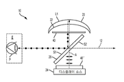
도 6의 개략적인 측면도는 빔 스플리터 플레이트(26)에서 빛을 지향시키기 위해 편광을 이용하는 대안 실시예를 도시한다. 이미지 발생기(24)는 제1 편광 상태(예를 들어, p-편광)를 가진 편광된 빛으로서 이미지 콘텐츠를 제공한다. 편광 빔 스플리터로 구성된 빔 스플리터 플레이트(26)는 제1 상태(p-편광, 화살표로 도시됨)를 전송하고 직교 상태(s-편광, 점으로 도시됨)를 반사한다. 1/4 파장 플레이트(40', quarter wave plate)을 통해 지나가는(통과하는) 둘은 빔 스플리터 플레이트(26)로부터의 반사를 위해 제1 (p-)편광 상태를 직교 (s-)편광 상태로 변형시킨다. 상기 파장 플레이트(40')는 1/4 파장 리타더(quarter wave retarder)(또한 본원에서 1/4 파장 플레이트로도 나타냄)일 수 있다. 파장 플레이트(40')는 무채색(achromatic) 1/4 파장 플레이트일 수 있다. 바람직하게, 파장 플레이트(40')는 가시 스펙트럼을 가로지르는 무채색일 수 있다. 도 6a의 실시예에서, 파장 플레이트(40')는 렌즈(L1)와 빔 스플리터 플레이트(26) 사이에 위치한다. 도 6b는 도 6a와 유사하지만 이 실시예가 이미지 발생기(24) 옆에 위치한 편광 플레이트(40'')를 활용한다는 것을 나타낸다. 편광 플레이트(40'')는 이미지 발생기(24)로부터 빛을 편광시키는 기능을 하며 가시 스펙트럼을 가로질러 무채색이다.The schematic side view of FIG. 6 illustrates an alternative embodiment that utilizes polarization to direct light at
도 7의 사시도는 물체 장면의 제한된 가시성을 허용하는 대안 실시예를 나타낸다. 우측 가상 이미지 형성 기기(10R)을 위한 렌즈(L2)는 시선(12)을 부분적으로 차단하도록 배치되고; 좌측 가상 이미지 형성 기기(10L)를 위한 렌즈(L1)는 다른 도면에 도시된 동일한 위치를 가지며, 빔 스플리터 플레이트(26)를 통과하는 물체 장면의 가시성을 허용한다. The perspective view of Figure 7 illustrates an alternative embodiment that allows limited visibility of the object scene. The lens L2 for the right virtual
완전한 가상-현실 보기를 위해, 렌즈(L1, L2) 모두는 시선(12)을 차단하도록 배치될 수 있다.For a complete virtual-reality view, all of the lenses L1, L2 may be arranged to block the line of
이미지 발생기Image generator
본원에 사용된 것처럼, 이미지 발생기(24)는 보는 사람의 한쪽 또는 두 눈에 대해 이미지를 형성하기 위한 이미지를 포함하는 빛을 방출할 수 있는 임의의 소스(source)일 수 있으며, 핸드-헬드 개인 통신 장치, 스마트폰, 패드, 컴퓨터 스크린, 또는 다른 디스플레이 소스 또는 이미지 투사 소스(image projection source)를 포함한다. 일부 실시예에서, 이미지 발생기는 평평한 이미지를 포함하는 빛을 방출할 수 있으며, 즉, 전송되는 이미지는 만곡되지 않은 이미지다. 사용될 수 있는 이미지 발생기 장치는 휴대폰과 같은 평평한 패널의 개인 통신 장치를 포함할 수 있으며, 일부 형식의 모바일 운영 시스템을 제공하는 이른바 "스마트폰", 적어도 일부의 컴퓨팅 및 디스플레이 성능을 갖춘 피처폰(feature phones), "스마트 와치", 및 다양한 형식의 전자식 패드, 컴퓨터화된 타블렛, 및 그래픽 콘텐츠를 디스플레이할 수 있는 적어도 하나의 디스플레이 영역을 포함하는 유사 장치를 포함할 수 있다. 본 발명의 기기는, 앞선 표에서 주어진 값으로부터 명확하게 알 수 있는 것처럼, 스마트폰 또는 다른 형식의 휴대용, 개인 통신 장치에서 발생된 이미지를 사용하는 분야에 특히 매우 적합하다. 일부 실시예에서, 이미지 발생기(24)는 GPS 센서, 사용자에 의해 보여지는 장면을 보고 찍는 제1 카메라, 및 제1 카메라의 반대 방향으로 향하고 있는 추가 "셀피(selfie) 카메라" 중 적어도 하나를 포함하는 스마트폰 장치이다. As used herein,
이미지 발생기(24)는 임의의 이미지 생성 소스일 수 있으며, 인간의 눈에 의해 이미지 디스플레이 장치로서 사용될 필요는 없다. 일부 실시예에 따라, 이미지 발생기는 이미지 투사를 가진 스크린으로서 다른 장치(예, 프로젝터)에 의해 거기에 투사된다.The
이미지를 포함하는 빛을 발생하는데 적합하게 조정될 수 있는 다른 형식의 이미지 발생기는 다양한 형식의 공간 광 변조기(spatial light modulator, SLM) 구성요소를 포함한다. 텍사스, 달라스, Texas Instruments의 디지털 광 프로세서(DLP); 예컨대, 액정 장치(LCD), 유기발광 다이오드(OLED), LCOS(액정 온 실리콘) 장치, 또는 그레이팅 전자기계 장치(grating electromechanical device)를 포함하는, 다양한 형식의 SLM 장치가 사용될 수 있다. 선형 광 변조기가 대안으로 사용될 수 있다.Other types of image generators that can be tailored to generate light including images include various types of spatial light modulator (SLM) components. Texas Instruments' Digital Optical Processor (DLP); Dallas, Texas; Various types of SLM devices may be used, including, for example, a liquid crystal device (LCD), an organic light emitting diode (OLED), an LCOS (liquid crystal on silicon) device, or a grating electromechanical device. A linear optical modulator may be used as an alternative.
빔 스플리터 플레이트(26)The beam splitter plate (26)
바람직하게, 본원에 개시된 실시예를 통해, 오직 빔 스플리터 플레이트(26)만이 보는 사람의 시선(12)에 놓인다. 이러한 배열은 유리 플레이트에 의해 가로막히지 않는 시선으로부터 수직으로 단지 약간 오프셋된 시야로, 매우 넓은 물체 장면 콘텐츠에 대한 수평 시야(FOV)를 제공한다.Preferably, through the embodiments disclosed herein, only the
실시예에 따라, 빔 스플리터 플레이트(26)는 50 각초(arc seconds) 이하 이내, 더욱 바람직하게 30 각초 이내, 또는 20 각초 이내와 같은, 타이트한 허용 오차 이내로 평행한 표면을 가진 유리 기판에 형성될 수 있다. 일부 실시예에서, 빔 스플리터(26)의 유리 기판은 10 각초(예, 8 내지 10 각초) 이하 이내로 평행한 표면을 갖는다. 평행한 표면은 고스팅(ghosting) 및 약간의 웨지형 빔 스플리터 표면으로 야기될 수 있는 다른 영향을 최소화하여, 매우 바람직하다.According to an embodiment, the
빔 스플리터 플레이트(26)는 융합 인발 공정을 이용하여 얻어진 유리 시트에 형성될 수 있다. 이러한 방법은 매우 평행한 양쪽 측면을 가진 유리 시트를 제공한다. 유리의 표준 형식은 빔 스플리터 플레이트 표면이 매우 평행하지 않은 경우 일어날 수 있는 고스팅을 줄이기 위해 이중 측면 폴리싱을 필요로 할 수 있다.The
이상적으로, 빔 스플리터 플레이트(26)는 가능한 넓은 시야를 허용하기 위해, 가능한 얇아야 한다. 일부 실시예에서, 빔 스플리터 플레이트(26)는 4 mm 이하의 폭을 갖으며, 더욱 바람직하게 3 mm 이하, 더욱 바람직하게 2 mm 이하, 및 더욱 바람직하게 1 mm (예컨대, 0.3 내지 0.7 mm) 이하의 두께를 갖는다. 그러한 작은 두께를 가진 빔 스플리터를 포함함으로써, 이미지를 포함하는 빛이 보는 사람의 눈을 행해 모든 표면에서 반사될 때, 이들 두 반사 사이의 거리는 보는 사람에게 이중 이미지로 "보이지" 않기에 충분히 작다. 일부 실시예에서, 빔 스플리터 플레이트(26)는 제1 및 제2 주 표면을 가지며 빔 스플리터 플레이트의 이들 표면은 50 각초 이내의 다른 평행한 톤(tone)이다. 일부 실시예에서, 빔 스플리터 플레이트(26)는 제1 및 제2 주 표면을 가지며 빔 스플리터 플레이트의 이들 표면은 1 각분 이내, 또는 75 각초, 더욱 바람직하게 55 각초 이내, 45 각초 이내, 및 더욱 바람직하게 40 각초 이내로 서로 평행하다. 일부 실시예에서, 빔 스플리터 플레이트(26)는 제1 및 제2 주 표면을 가지며 빔 스플리터 플레이트의 이들 표면은 30 또는 20 각초 이내로 서로 평행하다. 빔 스플리터 플레이트는, 예를 들어, 코닝사(Corning Incorporated)의 융합 형성된 유리로 만들어질 수 있으며 10 각초 (예, 4 내지 10 각초) 이내로 평행한 표면을 가질 수 있다. 일부 실시예에서, 빔 스플리터 플레이트(26)는 고저간(peak to valley, PV) 20 microns 이하의 평탄도 및 0.025 mm 이하의 두께 변화(유리의 중심 90 % 구역 이상(예, 유리 구역의 적어도 95 % 이상) 또는 적어도 이미지가 보여지는 구역에서)를 갖는다. 일부 실시예에서, 빔 스플리터 플레이트(26)는 10 microns 이하의 평탄도(고저간, PV) 및 0.02 mm 이하의 두께 변화(예, 0.002 mm 내지 0.01 mm)를 갖는다. 일부 실시예에서, 빔 스플리터 플레이트(26)는 7 microns 이하의 평탄도(PV)(예, 4 또는 5 microns PV) 및 표면의 길이를 가로질러, 즉, 예를 들어, 75 mm, 또는 100 mm, 또는 빔 스플리터의 길이를 가로질러 0.015 mm 이하의 두께 변화, 또는 0.01 mm 또는 그 이하(예, 0.002 mm, 0.005 mm, 또는 0.01 mm 또는 그들 사이)의 변화를 갖는다. Ideally, the
30 각초 또는 그 이하 이내로 서로 평행한 표면을 가진 전체 두께 변화가 0.02 mm 이하인 빔 스플리터 유리의 예시는 뉴욕, 코닝의 코닝사에서 이용 가능한 Gorilla® glass, LotusTM XT glass, LotusTM NXT glass, 또는 EAGLE XG® glass 이다. 그러한 평탄도 및 두께 정확도를 가진 유리를 이용하는 것은 양 표면에서 이미지가 반사되는 경우, 가상으로 동일한 위치에서 망막에 다다르게 매우 가깝게 위치하기 때문에, 고스트 이미지 없는 매우 개선된 이미지 품질을 야기한다. 빔 스플리터 플레이트는 바람직하게 한쪽 측면에 부분 반사 코팅으로 코팅되고 다른 측면에 반사 방지(AR) 코팅이 코팅된다. 디스플레이 시스템에 대한 피크 효율은 부분 반사기(partial reflector)가 거의 50 % 반사에 도달할 때(스펙트럼의 가시 영역을 가로질러 평균 50 % 반사율을 의미함) 얻어지며, 예를 들어, 부분 반사기가 약 40 % - 60 % 사이에 도달할 때, 더욱 바람직하게 스펙트럼의 가시 영역을 가로질러 약 45 - 55 % 반사율 사이에 도달할 때, 그리고 다른 측면에 반사 방지 코팅이 적용될 때 얻어진다. 예를 들어, 알루미늄 금속 코팅은 그러한 부분적인 반사율을 얻기 위해 증발 코팅 기술을 이용하여 적용될 수 있다.Examples of beam splitter glasses having a total thickness variation of less than 0.02 mm with a mutually parallel surface within 30 seconds or less are Gorilla glass, Lotus TM XT glass, Lotus TM NXT glass, or EAGLE XG glass available from Corning, Corning, ® glass. Utilizing glass with such flatness and thickness accuracy results in highly improved image quality without ghost images because images are reflected very close to the retina at virtually the same location when images are reflected from both surfaces. The beam splitter plate is preferably coated with a partially reflective coating on one side and an antireflective (AR) coating on the other. The peak efficiency for a display system is obtained when the partial reflector reaches approximately 50% reflection (meaning an average 50% reflectance across the visible region of the spectrum), for example, when the partial reflector is about 40 % -60%, more preferably between about 45-55% reflectance across the visible region of the spectrum, and when an antireflective coating is applied to the other side. For example, an aluminum metal coating can be applied using evaporative coating techniques to achieve such partial reflectivity.
일부 실시예에서, 반사 방지 코팅은 10 % 이하, 더욱 바람직하게 5 % 이하, 더욱 바람직하게 2 % 이하 및 가장 바람직하게는 1 % 이하 또는 0.5 % 이하의 반사율을 나타낸다(스펙트럼의 가시 영역을 가로질러 평균 0.5 % 이하의 반사율을 의미함). 예를 들어, 증발 코팅 기술을 이용하여 적용될 수 있는 것처럼, 유전체 층 또는 레이어의 유전체 적층은 그러한 반사 방지 성능을 얻는데 활용될 수 있다. 이는 또한 실제의 물체 장면으로부터의 빛의 50 %를 차단할 것이다. 빔 스플리터의 반사가 감소하면서, 디스플레이 이미지는 어두워지고 외부 장면이 더 밝아진다. 따라서, 이러한 코팅 변수를 변화시키는 것은 디스플레이로부터의 빛 수준과 외부 장면의 균형에 도움을 줄 수 있다.In some embodiments, the antireflective coating exhibits a reflectivity of less than 10%, more preferably less than 5%, more preferably less than 2%, and most preferably less than 1% or less than 0.5% (across the visible region of the spectrum Average reflectance of 0.5% or less). For example, as can be applied using evaporative coating techniques, dielectric layers of dielectric layers or layers can be utilized to obtain such antireflective performance. It will also block 50% of the light from the actual object scene. As the reflection of the beam splitter decreases, the display image becomes darker and the external scene becomes brighter. Thus, changing these coating parameters can help balance the light level from the display and the external scene.
렌즈(L1, L2)The lenses L1 and L2,
렌즈(L1, L2)는 몰딩 성형된 플라스틱(molded plastic) 또는 유리일 수 있다. 재료의 선택은 이미지의 색수차에 영향을 미칠 수 있다. 예를 들어 아크릴(acrylic)(PMMA)과 같은 저 분산의 재료(아베수(Abbe number) Vd > 40)는 색수차를 줄이는데 사용될 수 있다. 따라서, 일부 실시예에서, 렌즈(L1, L2)의 아베수 V는 ≥ 50, ≥ 55, 예를 들어 50 내지 70 사이, 또는 50 내지 60 사이이다. 하나의 예시 실시예에서 Vd는 약 57이다. The lenses L1 and L2 may be molded plastic or glass. The choice of material can affect the chromatic aberration of the image. For example, a low dispersion material (Abbe number Vd> 40) such as acrylic (PMMA) can be used to reduce chromatic aberration. Thus, in some embodiments, the Abbe number V of the lenses L1, L2 is ≥ 50, ≥ 55, for example between 50 and 70, or between 50 and 60. In one exemplary embodiment, Vd is about 57.
렌즈(L1, L2)는 각각 모놀리식(monolithic)이다. 모놀리식 렌즈는 단일 부품으로 제조된다. 이는, 예를 들어, 더블릿(doublet)과 같은, 다중 부품을 함께 접착하여 형성된 더블릿 또는 다른 복합 렌즈 조립체와 모놀리식 렌즈를 구별한다. 본원에 개시된 실시예에서, 렌즈(L1, L2)는 총 5 grams 내지 80 grams (예, 40 - 65 grams)의 무게를 갖는다.The lenses L1 and L2 are each monolithic. Monolithic lenses are made of a single part. This distinguishes monolithic lenses from doublet or other compound lens assemblies formed, for example, by bonding together multiple components, such as a doublet. In the embodiment disclosed herein, the lenses L1, L2 have a total weight of 5 grams to 80 grams (e.g., 40-65 grams).
일부 실시예에 따라, 렌즈(L1, L2)는 서로 접촉한 상태로 위치된다. 일부 실시예에 따라, 렌즈(L1, L2)는 하나의 모놀리식 구성요소로서 함께(예, 몰딩 성형되어) 형성된다. 본원에 개시된 실시예에 따라, 렌즈(L1, L2)는 사용자의 코에 대해 적어도 그 사이에 부분적으로 맞춰지기 위한 공간을 제공하도록 형성 또는 성형된다. 예를 들어, 렌즈(L1, L2)는 "코 삽입 공간"을 생성하기 위해 노치(notch) 또는 챔퍼(chamfer)를 갖춘 모놀리식 구조로 함께 몰딩 성형될 수 있다.According to some embodiments, the lenses L1 and L2 are positioned in contact with each other. According to some embodiments, the lenses L1, L2 are formed together (e.g., molding molded) as one monolithic component. According to the embodiment disclosed herein, the lenses L1, L2 are formed or shaped to provide at least a space for being partially aligned with the nose of the user. For example, the lenses L1 and L2 may be molded together into a monolithic structure with a notch or chamfer to create a "nose insertion space ".
일부 실시예에 따라, 렌즈(L1, L2)의 반사 및 굴절 표면은 상기 렌즈의 광학축이 서로 1 각분 이내로 평행하고 50 mm 내지 80 mm(예, 60 mm - 70 mm) 사이의 거리만큼 서로 이격되도록 구성된다.According to some embodiments, the reflective and refractive surfaces of the lenses L1, L2 are arranged such that the optical axes of the lenses are parallel to one another within a distance of one another and are spaced apart from one another by a distance of between 50 mm and 80 mm (e.g., 60 mm - 70 mm) .
반사 코팅(20')은 반월판 렌즈(L1)(및/또는 L2)의 볼록한 외부 표면(20)에 대해 적용된다. 반사 코팅은 실시예에 따른 이색성 코팅(dichroic coating)이다. 대안으로, 금속 코팅이 적용될 수 있다. The reflective coating 20 'is applied to the convex
전술한 바와 같이, 렌즈(L1, L2)는 단일 몰딩 성형된 조립체로서 함께 연결되어 형성될 수 있다. 대안으로, 렌즈(L1, L2)는 다이아몬드 선삭으로 제조될 수 있다. 통상적인 렌즈 두께는 예를 들어, 4 - 10 mm, 5 내지 9 mm일 수 있다.As described above, the lenses L1 and L2 may be formed as a single molded molded assembly connected together. Alternatively, the lenses L1 and L2 may be made of diamond turning. Typical lens thicknesses may be, for example, 4-10 mm, 5-9 mm.
하나의 예시의 실시예에서, 렌즈(L1, L2)는 아크릴이며, 각 렌즈는 하기의 수식으로 설명되는 8 mm의 중심 두께와 두 개의 비구면 표면(20, 22)을 갖는다. In one exemplary embodiment, the lenses L1 and L2 are acrylic, and each lens has two

여기서, r은 렌즈 표면의 꼭지점을 따른 반지름 거리이며, z는 높이 r에서 표면의 처짐이며, c는 표면 곡률(C = 1/Ri, 여기서 Ri는 표면 i의 반경이다)이고, k는 원뿔 상수이며, A, B, 및 C는 고차 비구면계수이다. 본원에 개시된 예시의 실시예에서, 비구면 표면(20, 22)은 제로가 아닌 비구면계수 A, B, 또는 C 중 적어도 하나를 갖는다. 예를 들어, 하기의 표 2의 실시예에서, 렌즈(L1, L2)의 렌즈 표면(20)과 연관된 비구면계수 A, B, 및 C는 모두 제로가 아니다. Where r is the radial distance along the vertex of the lens surface, z is the deflection of the surface at height r, c is the surface curvature (C = 1 / Ri, where Ri is the radius of surface i) , And A, B, and C are higher order aspheric coefficients. In the exemplary embodiment disclosed herein, the
표 2에서, 표면 1은 오목한 굴절 표면(22)에 상응하며, 표면 2는 볼록한 표면(20)에 상응하며 거기에 반사 코팅을 갖는다. 이러한 실시예에서, 상기 표면(22)의 꼭지점으로부터 이미지 발생기(24)의 표면(24')까지의 거리는 55.28 mm이다. 빔 스플리터(26)와 렌즈(L1, L2) 사이의 거리는 빔 스플리터가 동공과 정렬되도록 선택된다. 이러한 실시예에서, 렌즈(L1, L2)는 몰딩 성형된다. 대안 실시예에서, 표면(20,22)은 다이아몬드 선삭될 수 있다.In Table 2,
패킹 옵션Packing Options
본 발명의 기기는 종래의 안경형 프레임, 헤드밴드, 또는 헤드에 대해 디스플레이를 장착하는 다른 메커니즘을 이용하여, 헤드-장착 장치의 일부로서 조립될 수 있다. 기기는 대안으로, 의도된 적용에 따라, 헤드 커버링, 모자, 또는 헬멧에 연결될 수 있다.The device of the present invention can be assembled as part of a head-mounted device using a conventional eyeglass frame, headband, or other mechanism for mounting the display to the head. The device may alternatively be connected to the head covering, cap, or helmet, depending on the intended application.
본 발명의 실시예는 빔 스플리터 플레이트(26)의 작은 부품 수, 완화된 공차, 감소된 중량, 및 구조적 강성의 장점을 취해 디스플레이 기기(30)에 대한 다수의 개선된 패키징 배열을 허용할 수 있다.Embodiments of the present invention may allow for a number of improved packaging arrangements for
도 8a 및 8b의 측면도는 본 발명의 실시예에 따라 디스플레이 기기(30)의 접을 수 있는 버젼에 대한 계략도를 나타낸다. 빔 스플리터 플레이트(26)는 빔 스플리터 플레이트(26)의 에지를 따르는 것처럼, 제1 힌지(42) 또는 다른 형식의 유연한 커플링을 통해 렌즈(L1, L2)에 유연하게 연결된다. 제2 힌지(44)는 예를 들어, 스마트폰 장치의 임시 삽입 및 쉬운 제거를 위한 하우징과 같은, 이미지 발생기(24)를 지지하는 하우징 또는 프레임(46)에 빔 스플리터 플레이트(26)를 연결한다. 도 8a는 보기 위한 구성의 디스플레이 기기(30)를 나타낸다. 도 8b는 이미지 발생기(24)가 제거된, 운반 또는 보관을 위해 접혀진 디스플레이 기기(30)를 나타낸다. 적은 수의 기계 구성요소만을 이용하여, 수직 방향에 대해 접혀질 수 있는 디스플레이 기기(30) 버젼을 제공하기 위해 많은 가능한 기계적 배열이 고안될 수 있다는 것을 알 수 있다.8A and 8B show schematic diagrams of a collapsible version of the
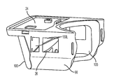
도 9는 기계 하우징(90)을 포함하는 디스플레이 기기(30)의 하나의 실시예를 나타낸다. 이러한 실시예에서, 이미지 발생기(24)(예, 디스플레이 표면(24')을 가진 폰, 도시되지 않음)는 눈 높이 위에 하우징(90)에 장착된다. 표면(24')은 하우징(90) 내에서, 안쪽에 위치된 광학 구성요소를 향하도록 지향된다. 보는 사람이 보게 되는 물리적 장면으로부터의 빛은 시선(12)(도 1 참고)을 따라 (하우징(90) 안쪽에 위치된) 빔 스플리터(26)를 통해 보는 사람의 눈으로 전송되며, 증강 현실(AR) 이미지를 형성하기 위해, 이미지 발생기(24)로부터의 빛과 결합된다. 하우징(90)은 또한 외부 보호 쉴드(100)를 지지한다. 외부 보호 쉴드(100)는 먼지와 손상으로부터 디스플레이 기기(30)의 광학 구성요소를 보호하기 위해 폴리카보네이트와 같은 플라스틱으로 만들어질 수 있다. 외부 보호 쉴드(100)는 또한, 예를 들어, 뉴욕, 코닝의 코닝사에서 이용가능한 Gorilla® glass 와 같은 스크래치 방지 템퍼링된(tempered) 유리로 이루어질 수 있다. 보호 쉴드는 반사 방지 코팅 또는 보는 사람의 눈으로 들어오는 실제 장면으로부터의 빛의 양을 조절하는 흡수 코팅으로 코팅될 수 있다. 예를 들어, 일부 실시예에서, 외부 보호 쉴드(100)는 포토크로믹 재료, 또는 편광자(polarizer)를 포함할 수 있다. 이러한 실시예에서, 물리적 장면에서의 빛은 외부 보호 쉴드(100)를 통해 디스플레이 기기(30)로 들어가고 이미지 발생기(24)에 의해 제공된 빛과 중첩된다.9 shows one embodiment of a
또한, 도 9에 도시된 것은 동력 활성기(110)(예, 스프링 플런저(spring plunger), 또는 버튼, 또는 다른 구성요소)이며, 적어도 부분적으로 하우징(90) 내에 위치되고, 이미지 발생기를 켜도록 사용자에 의해 맞물릴 때, 이미지 발생기(24) 상에서 동력 버튼을 밀게 된다.Also shown in Figure 9 is a power activator 110 (e.g., a spring plunger, or button, or other component) that is at least partially positioned within the
또한, 도 9에 도시된 것은 하우징(90)의 측면에 위치한 윈도우(130L)이며, 보는 사람/장치 사용자는 주변의 시야를 갖는다. 하우징(90)의 우측으로는 커팅된 상응하는 윈도우(130R)가 있다.Also shown in Fig. 9 is a
도 10은 도 9의 디스플레이 장치의 외부 보호 쉴드(100)와 내부 보호 쉴드(105)를 나타낸다. 내부 보호 쉴드(105)는 또한 먼지 등으로부터 광학 구성요소를 보호하며, 추가로, UV 빛으로부터(예, UV 코팅이 되어 있는 경우), 또는 다른 환경적 손상으로부터 보는 사람의 눈에 대한 추가 보호를 제공할 수 있다. 모든 쉴드(100, 105)는 폴리카보네이트로 만들어질 수 있다. 내부 보호 쉴드(105)는 미광(stray light) 및 눈부심을 줄이기 위해 반사 방지 코팅으로 코팅될 수 있다. 그러므로, 일부 실시예에 따라, 디스플레이 장치(30)는 빔 스플리터에 의해 결합되기 전에 물리적 장면으로부터의 빛을 전송하는 폴리카보네이트로 만들어진 만곡된 보호 쉴드(100)를 포함한다. 일부 실시예에 따라, 디스플레이 장치(30)는 빔 스플리터에 의해 결합된 후 물리적 장면으로부터의 빛을 전송하는 폴리카보네이트로 만들어진 만곡된 보호 쉴드(105)를 더욱 포함한다. 일부 실시예에 따라, 만곡된 보호 쉴드(105)는 보는 사람을 향한 측면에 반사 방지 코팅을 포함한다. 일부 실시예에 따라, 보호 쉴드(100)는 보는 사람을 향한 측면에 반사 방지 코팅을 포함한다. 일부 실시예에 따라, 보호 쉴드(100, 105) 중 적어도 하나는 올레오-포빅(oleo phobic) 및/또는 안티-포그(anti-fog) 코팅(도시되지 않음)을 포함한다.Fig. 10 shows an outer
이미지 발생기(24)는 이미지 발생기(24)를 통해 스프링 플런저(125R, 125L)로 힘을 가할 때 고정 나사(120R, 120L)를 이용하여 이미지 발생기를 회전시킴으로써 정렬될 수 있다. 도 11은 하우징(90)에 장착된 디스플레이 기기의 단면이다. 이 도면에서, (120R)은 이미지 발생기(24)를 통해 스프링 플런저(125R)로 힘을 가하는 고정 나사이다. 상응하는 고정 나사(120L) 및 스프링 플런저(125L)는 또한 주축(A)에 대해 이미지 발생기(24)를 회전시키는데 사용된다.The
일부 실시예에 따라, 디스플레이 장치(30)는 반사 표면의 주축에 평행한 축을 중심으로 이미지 발생기의 회전을 조정하는 수단을 포함한다. 도 11은 또한 빔 스플리터 (26)를 지지하기 위한 내부 몰딩 성형된 지지 구조(26s)를 포함하는 하우징(90)을 나타낸다.According to some embodiments, the
도 12는 도 9와 유사하지만, 이미지 발생기(24)와 관련된 이미지 시스템(240)의 보는 방향을 접는 광학 구성요소(250)를 포함하는 디스플레이 기기가 추가로 도시된다. 예를 들어, 도 12 실시예에서, 이미지 발생기(24)는 카메라(240)를 포함하는 휴대폰(휴대폰의 이미징 시스템)이다. 접는 거울 또는 프리즘과 같은 광학 구성요소(250)는 카메라(240)에 인접하게 위치한다. 광학 구성요소(250)는 카메라의 보는 방향을 접도록 구성된다. 따라서, 카메라는 빔 스플리터를 통해 보는 사람에 의해 보여진 시야의 적어도 일부를 "보거나" 또는 "볼" 수 있다. 즉, 광학 구성요소(250)의 도움으로 카메라는 보는 사람이 보는 동일한 방향으로 "볼" 수 있다. 예를 들어, 일부 실시예에서, 광학 구성요소(250)는 카메라의 시야가 빔 스플리터를 통해 보는 사람의 시선을 포함하도록 반사 표면을 포함한다. 반사 표면은 예를 들어, 반사 코팅에 의해 형성될 수 있다. 디스플레이 장치는 최종 사용자의 사진을 찍기 위해("셀피(selfie)") 구성되고 위치된 휴대폰의 카메라와 같은 적어도 하나의 이미징 시스템(240')을 더욱 포함할 수 있다. 이미징 시스템(240')(예, 카메라 렌즈)은 조절되거나, 또는 보는 사람의 눈에 빔 스플리터를 통해 "보기" 위해 (전술한 광학 구성요소(250)와 유사할 수 있는) 광학 접이식 광학 구성요소(250')와 함께 예시되어, 보는 사람이 보는 곳을 추적한다. Figure 12 is further illustrated with a display device similar to Figure 9, but including an
도 13은 또한 도 9와 유사하지만, 태양을 차단하기 위해(태양 눈부심을 최소화하기 위해) 적어도 하나의 차양(300A, 300B)을 포함하는 디스플레이 기기가 추가로 도시된다. 도시된 실시예에서, 차양(300A)은 힌지 연결되어 그 위치(각도)는 필요에 따라, 보는 사람에 의해 조절될 수 있다. 대안의 차양(300B)은 화살표 A-A로 나타낸 방향으로, 필요에 따라, 위치 내에서 그리고 위치 밖으로 미끄러질 수 있다. 일부 실시예에 따라(도시되지 않음) 측면 차양은 또한 측면 윈도우 (및 주변 윈도우(130L. 130R)) 위에 배치될 수 있다. 차양(300A, 300B)과, 더불어 측면 차양은 태양 눈부심을 최소화하기 위해 불투명할 수 있고, 또는 편광자를 포함할 수 있고 또는 포토크로믹 재료를 포함할 수 있다.Fig. 13 is also similar to Fig. 9 but additionally shows a display device including at least one
일부 실시예에 따라(도시되지 않음), 디스플레이 기기는 GPS 센서, 적어도 하나의 헤드 추적 센서, 눈 추적 센서, 가속도계, 또는 보는 사람의 눈에서 빔 스플리터를 통해 보는 두 렌즈 사이에 위치한 카메라 중 적어도 하나를 포함한다. According to some embodiments (not shown), the display device may include at least one of a GPS sensor, at least one head tracking sensor, an eye tracking sensor, an accelerometer, or a camera located between two lenses viewed through a beam splitter in the eye of the viewer .
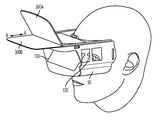
도 9-12에 도시된 실시예에서 이미지 발생기(24)가 보는 사람의 눈 위에 위치되고, 렌즈는 보는 사람의 눈 아래에 위치된다는 것을 알아야 한다. 그러나, 본원에 도시된 모든 실시예에서, 이미지 발생기(24)는 보는 사람의 눈 아래에 위치할 수 있고, 렌즈(L1)는 보는 사람의 눈 위에 위치된다. 즉, 장치 방향은 도 9-12에 도시된 것에 대해 180도 "반전"되고, 이는 태양 광선이 렌즈(L1, L2)의 굴절 표면에 부딪치는 것을 방지하기 때문에, 태양 눈부심을 최소화시키는 장점이 있다(도 14 참고).It should be noted that in the embodiment shown in Figs. 9-12, the
도 9-12의 장치는 도 4a 및 도 5a에 도시된 것처럼 두 개의 이미지 발생기(24R, 24L)를 활용할 수 있다는 것을 알아야 한다. 두 개의 작은 이미지 발생기(24R, 24L)를 활용하는 것은 전체 디스플레이 장치의 크기를 바람직하게 줄인다. 이들 이미지 발생기(24R, 24L)는 보는 사람의 눈의 아래 또는 위에 위치할 수 있다. 디스플레이 장치는 예를 들어, 보는 사람의 눈에서 빔 스플리터를 통해 "보기" 위해 광학 접이식 광학 구성요소(250')와 함께 조정되거나 구성되는 하나 또는 두 개의 카메라(240')(도 14에 개략적으로 도시된 것처럼)를 추가로 포함할 수 있으며, 따라서 보는 사람이 보는 곳을 추적할 수 있다. 예를 들어, 이미징 시스템 또는 카메라(240')는 이미지 발생기(24R, 24L) 근처 또는 인접하여 위치될 수 있다. 대안으로, 하나 이상의 카메라(240')는 보는 사람의 눈에서 빔 스플리터를 통해 "보는" 두 개의 렌즈 사이에 위치될 수 있다. 카메라(240')는 또한 디스플레이 장치의 다른 곳에, 예를 들어, 보는 사람의 눈(또는 눈 동공)의 위치를 추적할 수 있도록 보호 쉴드(100 또는 105)에 위치되거나 또는 인접하게 배치될 수 있다. 이들 카메라(240')는 단독으로, 또는 다른 광학 구성요소와 함께, 보는 사람에 의해 보여진 실제 장면의 위치가 디스플레이 장치에 "알려"지도록, 그리고 AR 중첩의 가상 부분이 보는 사람에 의해 보여진 실제 장면으로 (눈에 대해) 적절한 위치에 놓여질 수 있도록 눈을 추적할 수 있다. 전술한 것처럼, 예를 들어, 다중 카메라를 통해, 렌즈/프리즘 시스템을 이용하여, 및/또는 반사기를 이용하여, 이미지를 적절한 위치로 다중 송신하도록 달성될 수 있다. 게다가, 하나 이상의 눈 추적 카메라(또는 사용자의 시선 추적 카메라)와 협력하는 소프트웨어 알고리즘를 사용하여 보는 사람이 보는 실제/현실 장면 상에 가상 이미지의 적절한 중첩을 생성할 수 있다.It should be noted that the apparatus of Figures 9-12 can utilize two
따라서, 본원에 개시된 것처럼, 디스플레이 시스템의 일부 실시예는 GPS 센서, 적어도 하나의 눈 추적(또는 눈 추적) 센서, 가속도계, 또는 보는 사람의 눈 또는 보는 사람에 의해 보여지는 장면을 통해 보는 카메라 중 적어도 하나를 추가로 포함한다.Thus, as disclosed herein, some embodiments of a display system may include at least one of a GPS sensor, at least one eye tracking (or eye tracking) sensor, an accelerometer, or at least one of a camera viewing through a scene viewed by a viewer's eye or viewer And one additional.
하기의 설명 A1-O13은 본원에 개시된 몇 가지 예시의 실시예를 추가로 설명한다.The following description A1-O13 further illustrates some exemplary embodiments disclosed herein.
A1. 일부 실시예에 따라, A1. According to some embodiments,
이미지를 포함하는 빛을 발생하는 적어도 하나의 이미지 발생기;At least one image generator for generating light including an image;
상기 이미지 발생기로부터 이격되고, 상기 이미지 발생기에 대해 오목한 비구면 입사 굴절 표면과 비구면 반사 표면을 가진 렌즈; 및A lens spaced from the image generator, the lens having a concave aspheric incidence refractive surface and an aspherical reflective surface relative to the image generator; And
상기 이미지 발생기와 렌즈 사이의 자유 공간에 배치되고 보는 사람의 시선에 대해 비스듬한 제1 및 제2 표면을 가진 빔 스플리터 플레이트;를 포함하며,And a beam splitter plate disposed in the free space between the image generator and the lens and having first and second surfaces that are angled with respect to the line of sight of the viewer,
상기 렌즈와 빔 스플리터 플레이트는 보는 사람의 시선을 따라 이미지를 포함하는 빛에 대한 뷰어 아이 박스를 형성하는, 디스플레이 기기.Wherein the lens and beam splitter plate form a viewer eye box for light including an image along a line of sight of the viewer.
A2. 일부 실시예에 따라, A1에 있어서, 상기 빔 스플리터 플레이트의 제1 및 제2 표면은 50 각초 이내로 평행한, 디스플레이 기기. A2. According to some embodiments, in A1, the first and second surfaces of the beam splitter plate are parallel to within 50 seconds.
A3-A4. 일부 실시예에서, 상기 빔 스플리터 플레이트의 제1 및 제2 표면은 40 각초로 평행하고, 일부에서는 20 각초 이내로 평행한, 디스플레이 기기. A3-A4. In some embodiments, the first and second surfaces of the beam splitter plate are parallel to 40 second angles, and in some cases, less than 20 second angles.
A5. 일부 실시예에 따라, A1 내지 A4 중 어느 하나에 있어서, A5. According to some embodiments, in any one of A1 to A4,
상기 이미지를 포함하는 빛의 경로에 필드 렌즈를 더욱 포함하는, 디스플레이 기기.Further comprising a field lens in the path of light comprising said image.
A6. 일부 실시예에 따라, A1 내지 A5 중 어느 하나에 있어서, A6. According to some embodiments, in any one of A1 to A5,
상기 빔 스플리터 플레이트는 편광 빔 스플리터이고, 빔 스플리터 플레이트와 렌즈 사이에 배치된 1/4 파장 플레이트를 더욱 포함하는, 디스플레이 기기.Wherein the beam splitter plate is a polarizing beam splitter and further comprises a quarter-wave plate disposed between the beam splitter plate and the lens.
A7. 일부 실시예에 따라, A1 내지 A6 중 어느 하나에 있어서, A7. According to some embodiments, in any one of A1 to A6,
상기 빔 스플리터에 의해 결합된 이후 물리적 장면으로부터의 빛을 전송하는 만곡된 보호 쉴드를 더욱 포함하는, 디스플레이 기기,Further comprising a curved protective shield that transmits light from a physical scene after being coupled by the beam splitter,
A8. 일부 실시예에 따라, A7에 있어서, A8. According to some embodiments, in A7,
상기 만곡된 보호 쉴드는 보는 사람을 향한 측면에 반사 방지 코팅을 포함하는, 디스플레이 기기.Wherein the curved protective shield comprises an antireflective coating on a side facing the viewer.
A9. 일부 실시예에 따라, A1 내지 A8 중 어느 하나에 있어서, A9. According to some embodiments, in any one of A1 to A8,
상기 렌즈는 플라스틱 렌즈인, 디스플레이 기기.Wherein the lens is a plastic lens.
A10. 일부 실시예에 따라, A1 내지 A8 중 어느 하나에 있어서, A10. According to some embodiments, in any one of A1 to A8,
상기 렌즈는 아크릴 렌즈인, 디스플레이 기기.Wherein the lens is an acrylic lens.
A11. 일부 실시예에 따라, A1 내지 A10 중 어느 하나에 있어서, A11. According to some embodiments, in any one of A1 to A10,
상기 반사 표면의 주축에 평행한 축을 중심으로 이미지 발생기의 회전을 조정하도록 구성된 조정 구성요소를 더욱 포함하는, 디스플레이 기기.Further comprising an adjustment component configured to adjust rotation of the image generator about an axis parallel to the major axis of the reflective surface.
A12. 일부 실시예에 따라, A11에 있어서, A12. According to some embodiments, in A11,
상기 조정 구성요소는 한쪽 측면에 이미지 발생기를 결합시키는 적어도 하나의 나사와 다른 측면에 이미지 발생기를 결합시키는 적어도 하나의 스프링 플런저를 포함하는, 디스플레이 기기.Wherein the adjustment component comprises at least one screw for coupling the image generator to one side and at least one spring plunger for coupling the image generator to the other side.
A13. 일부 실시예에 따라, A11에 있어서, A13. According to some embodiments, in A11,
상기 조정 구성요소는 한쪽 측면에 이미지 발생기를 결합시키는 다수의 나사와 다른 측면에 이미지 발생기를 결합시키는 다수의 스프링 플런저를 포함하는, 디스플레이 기기.Wherein the adjustment component comprises a plurality of screws for coupling the image generator to one side and a plurality of spring plungers for coupling the image generator to the other side.
A14. 일부 실시예에 따라, A1 내지 A13 중 어느 하나에 있어서, A14. According to some embodiments, in any one of A1 to A13,
상기 이미지 발생기는 평평한 디스플레이 표면으로부터 이미지를 포함하는 빛의 평평한 필드를 발생하며; 상기 렌즈는 상기 반사 표면의 주축이 이미지 발생기에 수직하도록 이미지 발생기에서 이격되고; 상기 빔 스플리터 플레이트의 제1 및 제2 표면은 보는 사람의 시선에 대해 비스듬한 실질적으로 평행한 표면인, 디스플레이 기기.The image generator generating a flat field of light comprising an image from a flat display surface; The lens being spaced apart from the image generator such that the major axis of the reflective surface is perpendicular to the image generator; Wherein the first and second surfaces of the beam splitter plate are obliquely substantially parallel surfaces with respect to a line of sight of the viewer.
A15. 일부 실시예에 따라, A1 내지 A14 중 어느 하나에 있어서, A15. According to some embodiments, in any one of A1 to A14,
상기 빔 스플리터 플레이트는 이미지 발생기를 향한 측면에 반사 방지 코팅을 포함하는, 디스플레이 기기.Wherein the beam splitter plate comprises an anti-reflective coating on a side facing the image generator.
A16. 일부 실시예에 따라, A1 내지 A14 중 어느 하나에 있어서, A16. According to some embodiments, in any one of A1 to A14,
상기 빔 스플리터는 편광 빔 스플리터인, 디스플레이 기기.Wherein the beam splitter is a polarization beam splitter.
A17. 일부 실시예에 따라, A16에 있어서, A17. According to some embodiments, in A16,
상기 이미지 발생기에 인접한 편광 플레이트와 상기 렌즈와 빔 스플리터 사이에 위치한 1/4 파장 플레이트를 더욱 포함하는, 디스플레이 기기.Further comprising a polarizing plate adjacent to the image generator and a quarter wave plate positioned between the lens and the beam splitter.
A18. 일부 실시예에 따라, A1 내지 A17 중 어느 하나에 있어서, A18. According to some embodiments, in any one of A1 to A17,
보는 사람이 착용 가능한, 디스플레이 기기.A display device that can be worn by a viewer.
A19. A1 내지 A18 중 어느 하나에 있어서, A19. In any one of A1 to A18,
상기 빔 스플리터 플레이트는 융합 인발 공정을 이용하여 성형되는, 디스플레이 기기.Wherein the beam splitter plate is formed using a fusion drawing process.
A20. A14에 있어서, A20. In A14,
상기 빔 스플리터 플레이트의 제1 및 제2 표면은 30 각초 이내로 평행한, 디스플레이 기기.Wherein the first and second surfaces of the beam splitter plate are parallel within a half second.
A21. A14에 있어서, A21. In A14,
상기 빔 스플리터 플레이트는 편광 빔 스플리터이고 빔 스플리터 플레이트와 렌즈 사이에 배치된 1/4 파장 플레이트를 더욱 포함하는, 디스플레이 기기.Wherein the beam splitter plate is a polarization beam splitter and further comprises a quarter-wave plate disposed between the beam splitter plate and the lens.
A22. A14에 있어서, A22. In A14,
상기 이미지를 포함하는 빛의 경로에 필드 렌즈를 더욱 포함하는, 디스플레이 기기.Further comprising a field lens in the path of light comprising said image.
A23. A22에 있어서, A23. In A22,
상기 필드 렌즈는 이미지 발생기에 직접 인접하여 위치하고, 비구면 표면을 포함하는, 디스플레이 기기.Wherein the field lens is located directly adjacent to the image generator and comprises an aspherical surface.
A24. A1 내지 A23 중 어느 하나에 있어서, A24. In any one of A1 to A23,
상기 이미지 발생기는 유기발광 다이오드를 포함하는, 디스플레이 기기.Wherein the image generator comprises an organic light emitting diode.
A25. A1 내지 A24 중 어느 하나에 있어서, A25. In any one of A1 to A24,
상기 이미지 발생기는 개인 통신 장치를 포함하는, 디스플레이 기기.Wherein the image generator comprises a personal communication device.
B1. 디스플레이 기기로서, B1. As a display device,
a) 평평한 이미지 발생기;a) a flat image generator;
b) 상기 이미지 발생기에서 이격되고 이미지 발생기에 대해 오목한 비구면 입사 굴절 표면 및 비구면 반사 표면을 가진 렌즈, 여기서 상기 반사 표면의 주축은 상기 이미지 발생기에 수직임; 및b) a lens spaced from the image generator and having an aspherical incidence and refraction surface concave to the image generator, wherein the major axis of the reflective surface is perpendicular to the image generator; And
c) 상기 이미지 발생기와 렌즈 사이의 자유 공간에 보는 사람에 대한 물체 장면의 시선을 따라 배치되고, 시선에 대해 비스듬한 실질적으로 평행한 제1 및 제2 표면을 가진 빔 스플리터 플레이트;를 포함하고,and c) a beam splitter plate disposed in the free space between the image generator and the lens, the beam splitter plate being disposed along the line of sight of the object scene to the viewer and having substantially parallel first and second surfaces oblique to the line of sight,
상기 빔 스플리터 플레이트는 또한 상기 이미지 발생기로부터 렌즈로 이미지를 포함하는 빛을 전송하도록 배치되며, 상기 빔 스플리터 플레이트와 렌즈는, 비구면 입사 굴절 표면을 통과하는 제1 굴절을 위해 이미지를 포함하는 빛을 전달하고, 상기 굴절된 빛을 비구면 반사 표면으로부터 반사하고, 상기 반사된 빛을 비구면 입사 굴절 표면으로부터 다시 보는 사람의 시선을 따라 렌즈로부터 뷰어 아이 박스를 향해 상기 빛을 반사하는 빔 스플리터 플레이트로 굴절시키는, 광학 경로를 형성하는, 디스플레이 기기.The beam splitter plate is also arranged to transmit light comprising an image from the image generator to a lens, the beam splitter plate and lens transmitting light comprising an image for a first refraction through an aspherical incidence refractive surface Refracting the refracted light from an aspherical reflective surface and refracting the reflected light to a beam splitter plate reflecting the light from the lens toward the viewer eye box along the line of sight of the viewer again from the aspherical incidence refractive surface, And forms an optical path.
C1. 디스플레이 기기로서, C1. As a display device,
제1 및 제2 평행한 표면을 가지며 보는 사람의 시선을 따라 제1 뷰어 아이 박스를 형성하도록 배치된 제1 빔 스플리터 플레이트; 및A first beam splitter plate having first and second parallel surfaces and arranged to form a first viewer eye box along a line of sight of the viewer; And
상기 제1 뷰어 아이 박스에 제1 가상 이미지를 형성하기 위한 제1 가상 이미지 형성 기기;를 포함하되,And a first virtual image forming device for forming a first virtual image in the first viewer eye box,
상기 제1 가상 이미지 형성 기기는:Wherein the first virtual image forming apparatus comprises:
(i) 상기 제1 빔 스플리터 플레이트로부터 이격되고 이미지를 포함하는 빛의 제1 평평한 필드를 제1 빔 스플리터 플레이트의 제1 표면을 향해 지향시키는 제1 이미지 발생기; 및 (i) a first image generator for directing a first flat field of light spaced from the first beam splitter plate and comprising an image towards a first surface of a first beam splitter plate; And
(ii) 상기 제1 이미지 발생기에 대해 오목한 제1 비구면 입사 굴절 표면과 제1 이미지 발생기에 대해 오목한 제1 비구면 반사 표면을 가진 제1 렌즈, 여기서, 상기 제1 굴절 표면의 제1 주축은 상기 제1 이미지 발생기에 수직함;를 포함하는, 디스플레이 기기. (ii) a first lens having a concave first aspheric surface and a concave first aspheric surface for the first image generator, wherein the first major axis of the first refractive surface is the 1 < / RTI > image generator.
C2. C1에 있어서, C2. In C1,
제3 및 제4 평행한 표면을 가지며 보는 사람의 시선을 따라 제2 뷰어 아이 박스를 형성하도록 배치된 제2 빔 스플리터 플레이트; 및A second beam splitter plate having third and fourth parallel surfaces and arranged to form a second viewer eye box along a line of sight of the viewer; And
상기 제2 뷰어 아이 박스에 제2 가상 이미지를 형성하기 위한 제2 가상 이미지 형성 기기;를 포함하되,And a second virtual image forming device for forming a second virtual image in the second viewer eye box,
상기 제2 가상 이미지 형성 기기는:Wherein the second virtual image forming apparatus comprises:
(i) 상기 제2 빔 스플리터 플레이트로부터 이격되고 이미지를 포함하는 빛의 제2 평평한 필드를 제2 빔 스플리터 플레이트의 제3 표면을 향해 지향시키는 제2 이미지 발생기; 및 (i) a second image generator for directing a second flat field of light spaced from the second beam splitter plate and comprising an image towards a third surface of a second beam splitter plate; And
(ii) 상기 제2 이미지 발생기에 대해 오목한 제2 비구면 입사 굴절 표면과 제2 이미지 발생기에 대해 오목한 제2 비구면 반사 표면을 가진 제2 렌즈, 여기서, 상기 제2 굴절 표면의 제2 주축은 상기 제2 이미지 발생기에 수직함;를 포함하는, 디스플레이 기기. (ii) a second lens having a concave second aspheric surface and a concave second aspheric surface with respect to the second image generator, wherein the second major axis of the second refractive surface is the 2 image generator.
C3. C1에 있어서, C3. In C1,
상기 제1 및 제2 이미지 발생기는 이미지를 포함하는 빛을 대향하는 방향으로 지향시키는, 디스플레이 기기.Wherein the first and second image generators direct light including the image in opposite directions.
C4. A1, A14, B1, C1 또는 C2 중 하나에 있어서, C4. A1, A14, B1, C1 or C2,
상기 빔 스플리터 플레이트는 융합 인발 공정을 이용하여 형성되는, 디스플레이 기기.Wherein the beam splitter plate is formed using a fusion drawing process.
C5. C4에 있어서, C5. In C4,
상기 빔 스플리터 플레이트의 제1 및 제2 표면은 30 각초 이내로 평행한, 디스플레이 기기.Wherein the first and second surfaces of the beam splitter plate are parallel within a half second.
D1. 디스플레이 기기로서, D1. As a display device,
보는 사람의 상응하는 시선에 따라 좌안 및 우안 뷰어 아이 박스를 형성하도록 배치되고, 시선에 대해 비스듬한 제1 및 제2 평행한 표면을 가진, 빔 스플리터 플레이트;A beam splitter plate disposed to form a left eye and right eye viewer eye box according to a corresponding line of sight of the viewer and having first and second parallel surfaces tilted with respect to the line of sight;
상응하는 뷰어 아이 박스에서 보여지도록 상응하는 좌안 또는 우안 가상 이미지를 형성하도록 각각 배치되고, Respectively, to form a corresponding left-eye or right-eye virtual image to be viewed in a corresponding viewer eye box,
(i) 빔 스플리터 플레이트의 제1 표면을 향해 이미지를 포함하는 빛의 평평한 필드를 지향시키는 빔 스플리터 플레이트로부터 이격된 이미지 발생기; 및(i) an image generator spaced from a beam splitter plate that directs a flat field of light comprising an image toward a first surface of the beam splitter plate; And
(ii) 상기 빔 스플리터 플레이트의 제2 표면에서 이격되고, 상기 이미지 발생기에 대해 오목한 비구면 입사 굴절 표면과 이미지 발생기에 대해 오목한 비구면 반사 표면을 가진 모놀리식 렌즈, 여기서, 상기 반사 표면의 주축은 이미지 발생기에 수직임;를 포함하는 좌안 가상 이미지 형성 기기 및 우안 가상 이미지 형성 기기;를 포함하는, 디스플레이 기기.(ii) a monolithic lens spaced from a second surface of the beam splitter plate, the monolithic lens having a recessed aspheric incidence bending surface concave with respect to the image generator and a concave aspheric reflection surface with respect to the image generator, A left virtual virtual image forming device and a right virtual virtual image forming device, which are perpendicular to the generator.
D2. D1에 있어서, D2. In D1,
상기 빔 스플리터 플레이트의 제1 에지는 상기 모놀리식 렌즈에 힌지 연결되는, 디스플레이 기기.Wherein a first edge of the beam splitter plate is hinged to the monolithic lens.
D3. D1에 있어서, D3. In D1,
상기 빔 스플리터 플레이트의 제2 에지는 개인 통신 장치를 이미지 발생기로서 수용하는 하우징에 연결되는, 디스플레이 기기.And a second edge of the beam splitter plate is connected to a housing that houses the personal communication device as an image generator.
D4. A1 내지 D3 중 어느 하나에 있어서, D4. In any one of A1 to D3,
상기 기기는 수직 방향에 대해 접힐 수 있는, 디스플레이 기기.Wherein the device is foldable about a vertical direction.
D6. D1에 있어서, D6. In D1,
상기 가상 이미지 형성 기기의 적어도 하나에 대한 모놀리식 렌즈는 수평 시야의 일부를 차단하는, 디스플레이 기기.Wherein the monolithic lens for at least one of the virtual image forming devices blocks a portion of the horizontal field of view.
D7. A1, A14, B1, C1 및 D1에 있어서, D7. A1, A14, B1, C1 and D1,
상기 빔 스플리터 플레이트는 25 grams 이하의 무게를 가지며 40 도를 초과하는 수평 전체 시야를 제공하는, 디스플레이 기기.Wherein the beam splitter plate weighs less than 25 grams and provides a horizontal total field of view greater than 40 degrees.
D8. D7에 있어서, D8. In D7,
상기 빔 스플리터 플레이트는 2 내지 15 grams, 예를 들어, 3 - 15 grams, 2 - 10 grams, 또는 2 - 5 grams의 무게를 갖는, 디스플레이 기기.Wherein the beam splitter plate has a weight of between 2 and 15 grams, for example between 3-15 grams, 2-10 grams, or 2-5 grams.
D9. A1, A14, B1, C1 및 D1 에 있어서, D9. A1, A14, B1, C1 and D1,
상기 렌즈는 아크릴로 몰딩 성형되는, 디스플레이 기기.Wherein the lens is molded by acrylic molding.
D10. A1, A14, B1, C1 및 D1 에 있어서, D10. A1, A14, B1, C1 and D1,
물리적 장면으로부터의 빛은 빔 스플리터 플레이트를 통해 보는 사람의 눈으로 전송되고 이미지 발생기에 의해 제공된 빛과 결합되는, 디스플레이 기기.Wherein light from the physical scene is transmitted to the viewer's eye through the beam splitter plate and is coupled to light provided by the image generator.
D11. D9에 있어서, D11. In D9,
올레오-포빅 및/또는 안티-포그 코팅을 포함하는 만곡된 보호 쉴드를 더욱 포함하는, 디스플레이 기기.Further comprising a curved protective shield comprising an oleo-forbic and / or anti-fog coating.
D12. D9에 있어서, D12. In D9,
상기 빔 스플리터 플레이트에 의해 결합된 후 물리적 장면으로부터의 빛을 전송하는 폴리카보네이트로 만들어진 만곡된 보호 쉴드를 더욱 포함하는, 디스플레이 기기.Further comprising a curved protective shield made of polycarbonate that is coupled by the beam splitter plate and then transmits light from a physical scene.
D13. D10에 있어서, D13. In D10,
상기 빔 스플리터 플레이트에 의해 결합된 후 물리적 장면으로부터의 빛을 전송하는 폴리카보네이트로 만들어진 만곡된 보호 쉴드를 더욱 포함하는, 디스플레이 기기.Further comprising a curved protective shield made of polycarbonate that is coupled by the beam splitter plate and then transmits light from a physical scene.
D14. A14, B1, C1 및 D1에 있어서, D14. A14, B1, C1 and D1,
상기 주축에 평행한 축을 중심으로 상기 이미지 발생기의 회전을 조정하도록 구성된 조정 구성요소를 더욱 포함하는, 디스플레이 기기.Further comprising an adjustment component configured to adjust rotation of the image generator about an axis parallel to the major axis.
D15. D14에 있어서, D15. In D14,
상기 조정 구성요소는 스프링 플런저에 대해 이미지 발생기를 누르고 있는 나사를 포함하는, 디스플레이기 기기.Wherein the adjustment component comprises a screw pressing the image generator against the spring plunger.
D16. A1, A14, B1 및 C1 및 D1에 있어서, D16. A1, A14, B1 and C1 and D1,
상기 디스플레이 소스를 활성화시키기 위한 동력 활성기를 더욱 포함하는, 디스플레이 기기.And a power activator for activating the display source.
D17. A1 내지 D16 중 어느 하나에 있어서, D17. In any one of A1 to D16,
상기 렌즈는 5 내지 10 mm의 중심 두께를 가지며 하기 수식으로 설명되는 처짐, 즉 z를 가진 디자인의 두 개의 비구면 표면을 갖고, The lens has two aspheric surfaces of a design having a central thickness of 5 to 10 mm and a deflection,

상기 비구면 계수 A, B 또는 C 중 적어도 하나는 제로가 아닌, 디스플레이 기기.Wherein at least one of the aspheric coefficients A, B or C is not zero.
D18. A1 내지 D17 중 어느 하나에 있어서, D18. In any one of A1 to D17,
상기 빔 스플리터, 이미지 발생기, 및 렌즈의 치수 및 방향은 그 안에 가상 이미지가 형성되는 시야보다 더 큰 물체 장면을 위한 보는 사람의 시야를 야기하도록 선택되는, 디스플레이 기기.Wherein the dimensions and orientation of the beam splitter, image generator, and lens are selected to cause a view of the viewer for an object scene larger than the view in which the virtual image is formed.
E1. 디스플레이 기기로서, E1. As a display device,
보는 사람의 직접적인 시선에서 벗어난 이미지 발생기를 지지하기 위한 지지 구조, 여기서 상기 이미지 발생기는 이미지를 포함하는 빛을 발생할 수 있음; 및A support structure for supporting an image generator deviating from a direct line of sight of the viewer, wherein the image generator is capable of generating light comprising an image; And
상기 이미지 발생기와 렌즈 사이의 자유 공간에 배치되고 보는 사람의 시선에 대해 비스듬한 제1 및 제2 표면을 가진 평평한 빔 스플리터 플레이트;를 포함하는, 디스플레이 기기.And a flat beam splitter plate disposed in the free space between the image generator and the lens and having first and second surfaces that are angled with respect to the line of sight of the viewer.
E2. E1에 있어서, E2. In E1,
상기 이미지 발생기는 통신 장치인, 디스플레이 기기.Wherein the image generator is a communication device.
E3. A1 내지 E2 중 어느 하나에 있어서, E3. In any one of A1 to E2,
상기 이미지 발생기는 휴대폰인, 디스플레이 기기.Wherein the image generator is a cellular phone.
E5. A1 내지 E3 중 어느 하나에 있어서, E5. In any one of A1 to E3,
상기 디스플레이 장치는 적어도 하나의 이동 가능한 광학 구성요소를 포함하는, 디스플레이 기기.Wherein the display device comprises at least one movable optical component.
E6. E5에 있어서, E6. In E5,
상기 이동 가능한 광학 구성요소는 평평한 빔 스플리터 플레이트를 포함하는, 디스플레이 기기.Wherein the movable optical component comprises a flat beam splitter plate.
E7. E6에 있어서, E7. In E6,
상기 빔 스플리터 플레이트는 힌지 연결되는, 디스플레이 기기.Wherein the beam splitter plate is hinged.
E8. E1에 있어서, E8. In E1,
상기 이미지 발생기로부터 이격되고, 이미지 발생기에 대해 오목한 비구면 입사 굴절 표면과 이미지 발생기에 대해 오목한 비구면 반사 표면을 가진 렌즈를 더욱 포함하는, 디스플레이 기기.Further comprising a lens spaced from the image generator and having a concave aspheric incidence bending surface with respect to the image generator and a concave aspheric reflection surface with respect to the image generator.
E9. A1, A14, A1, A14, B1, C1, D1, 또는 E1 중 어느 하나에 있어서, E9. A1, A14, A1, A14, B1, C1, D1, or E1,
상기 렌즈 및 빔 스플리터 플레이트는 보는 사람의 시선을 따라 이미지를 포함하는 빛에 대한 뷰어 아이 박스를 형성하는, 디스플레이 기기.Wherein the lens and beam splitter plate form a viewer eye box for light including an image along a line of sight of the viewer.
F1. 보는 사람에게 이미지를 포함하는 빛을 전달하는 방법으로서, F1. CLAIMS What is claimed is: 1. A method of transmitting light comprising an image to a viewer,
보는 사람의 직접적인 시선 근처이지만 시선 밖에 위치한 이미지 발생기로부터 이미지를 포함하는 빛을 방출하는 단계;Emitting light including an image from an image generator located near the viewer's direct line of sight but outside the line of sight;
상기 이미지를 포함하는 빛을 빔 스플리터 플레이트를 통과하게 지향시키는 단계;Directing light comprising the image through a beam splitter plate;
상기 이미지를 포함하는 빛을 처음으로 굴절시키는 단계;Refracting light including the image for the first time;
상기 이미지를 포함하는 빛을 다시 렌즈로부터 상기 빔 스플리터를 향해 반사시키는 단계;Reflecting the light including the image back from the lens toward the beam splitter;
빔 스플리터로 전송하기 전, 이미지를 포함하는 빛을 두 번째로 굴절시키는 단계; 및Refracting the light containing the image a second time before transmitting it to the beam splitter; And
상기 두 번째 굴절 단계 이후, 빔 스플리터로부터 그리고 보는 사람의 시선으로 이미지를 포함하는 빛을 반사시키는 단계;를 포함하는, 방법.And after said second refracting step, reflecting light including an image from the beam splitter and into the line of sight of the viewer.
F2. F1에 있어서, F2. In F1,
상기 첫 번째 및 두 번째 굴절 단계와 첫 번째 및 두 번째 반사 단계는 이미지를 반사하는 단계는 반사하는 오목한 표면을 가진 단일 렌즈를 이용하여 달성되는, 방법.Wherein the first and second refraction steps and the first and second reflections are achieved using a single lens having a reflective concave surface for reflecting the image.
F3. F1에 있어서, F3. In F1,
상기 이미지를 포함하는 빛을 첫 번째로 굴절시키는 단계는 상기 이미지 발생기와 빔 스플리터 사이에 위치한 굴절시키는 빔을 통해 빔을 지나가는 단계를 포함하는, 방법.Wherein said first refracting light including said image comprises passing a beam through a refracting beam positioned between said image generator and a beam splitter.
G1. 디스플레이 기기로서, G1. As a display device,
(i) 이미지 발생기 디스플레이 표면으로부터 이미지를 포함하는 빛을 발생하는 이미지 발생기;(i) an image generator for generating light including an image from an image generator display surface;
(ii) 상기 이미지 발생기로부터 이격되고, 이미지 발생기에 대해 오목한 입사 굴절 표면 및 반사 표면을 가진 렌즈, 여기서, 적어도 하나의 렌즈 표면은 비구면 표면임; (ii) a lens spaced from the image generator, the lens having a concave incident refracting surface and a reflective surface relative to the image generator, wherein at least one lens surface is an aspherical surface;
(iii) 상기 이미지 발생기와 렌즈 사이의 자유 공간에 배치되고 보는 사람의 시선에 대해 비스듬한 제1 및 제2 표면을 가진 빔 스플리터 플레이트, 여기서, 상기 렌즈 및 빔 스플리터 플레이트는 보는 사람의 시선을 따라 이미지를 포함하는 빛을 위한 뷰어 아이 박스를 형성함; 및(iii) a beam splitter plate disposed in the free space between the image generator and the lens and having first and second surfaces that are angled with respect to the line of sight of the viewer, wherein the lens and beam splitter plate Forming a viewer eye box for light comprising; And
(iv) 상기 이미지를 포함하는 빛의 경로에서 이미지 발생기에 인접하게 위치하며 적어도 하나의 비구면 표면을 포함하는 필드 렌즈;를 포함하는, 디스플레이 기기.(iv) a field lens positioned adjacent to the image generator in the path of light comprising said image and comprising at least one aspherical surface.
G2. 디스플레이 기기로서, G2. As a display device,
이미지 발생기 디스플레이 표면으로부터 이미지를 포함하는 빛을 발생하는 이미지 발생기;An image generator for generating light including an image from an image generator display surface;
상기 이미지 발생기로부터 이격되고, 광학 축과, 이미지 발생기에 대해 오목한 입사 굴절 표면 및 반사 표면을 각각 포함하는 두 개의 렌즈, 여기서, 적어도 하나의 상기 표면은 비구면이고, 상기 표면은 상기 렌즈 각각의 광학 축이 서로 1 각분 이내로 평행하며 50 mm 내지 80 mm 사이의 거리로 서로 이격되도록 구성됨;Two lenses spaced from the image generator and each including an optical axis and a concave incident refracting surface and a reflective surface with respect to the image generator, wherein at least one of the surfaces is an aspherical surface, Are spaced apart from one another by a distance of between 50 mm and 80 mm;
상기 이미지 발생기와 렌즈 사이의 자유 공간에 배치되고 보는 사람의 시선에 대해 비스듬한 제1 및 제2 표면을 가진 빔 스플리터 플레이트;를 포함하고,And a beam splitter plate disposed in the free space between the image generator and the lens and having first and second surfaces that are angled with respect to the line of sight of the viewer,
여기서, 상기 렌즈와 빔 스플리터는 결합되어 보는 사람의 시선을 따라 이미지를 포함하는 빛을 제공하는, 디스플레이 기기.Here, the lens and the beam splitter are combined to provide light including an image along a line of sight of the viewer.
G3. D17, E1, G1 또는 G2 중 어느 하나에 있어서, G3. D17, E1, G1 or G2,
상기 렌즈는 중심 두께가 3 - 12 mm인, 디스플레이 기기. Wherein the lens has a center thickness of 3-12 mm.
G4. D17, E1, G1 또는 G2 중 어느 하나에 있어서, G4. D17, E1, G1 or G2,
상기 렌즈는 중심 두께가 3 - 10 mm인, 디스플레이 기기. Wherein the lens has a center thickness of 3 - 10 mm.
G5. D17, E1, G1 또는 G2 중 어느 하나에 있어서, G5. D17, E1, G1 or G2,
상기 렌즈는 중심 두께가 4 - 8 mm인, 디스플레이 기기. Wherein the lens has a center thickness of 4-8 mm.
G6. G1 내지 G5 중 어느 하나에 있어서, G6. In any one of G1 to G5,
상기 두 개의 렌즈는 총 5 - 80 grams의 무게를 갖는, 디스플레이 기기. Wherein the two lenses have a total weight of 5 to 80 grams.
G7. G6에 있어서, G7. In G6,
상기 빔 스플리터는 5 grams 이하의 무게를 갖는, 디스플레이 기기. Wherein the beam splitter has a weight of 5 grams or less.
G8. G7에 있어서, G8. In G7,
상기 빔 스플리터는 2 - 10 grams의 무게를 갖는, 디스플레이 기기. Wherein the beam splitter has a weight of 2 - 10 grams.
G9. G1 내지 G8 중 어느 하나에 있어서, G9 . In any one of G1 to G8,
상기 이미지 발생기는 "스마트폰"인, 디스플레이 기기. Wherein the image generator is a "smartphone. &Quot;
G10. A1 내지 G9 중 어느 하나에 있어서, G10 . In any one of A1 to G9,
상기 이미지 발생기는 하나 이상(예, 둘)의 OLED 장치를 포함하는, 디스플레이 기기. Wherein the image generator comprises one or more (e.g., two) OLED devices.
G11. A1 내지 G9 중 어느 하나에 있어서, G11 . In any one of A1 to G9,
상기 이미지 발생기는 액정 디스플레이를 가진 장치를 포함하는, 디스플레이 기기. Wherein the image generator comprises an apparatus having a liquid crystal display.
G12. A1 내지 G11 중 어느 하나에 있어서, G12 . In any one of A1 to G11,
GPS 센서, 헤드 추적 센서, 눈 추적 센서, 가속도계, 보는 사람의 눈에서 빔 스플리터를 통해 보이는 두 개의 렌즈 사이에 위치한 카메라 중 적어도 하나를 더욱 포함하는, 디스플레이 기기. Further comprising at least one of a GPS sensor, a head tracking sensor, an eye tracking sensor, an accelerometer, and a camera positioned between two lenses viewed through a beam splitter in a viewer's eye.
H1. 디스플레이 기기로서, H1 . As a display device,
이미지 발생기 디스플레이 표면으로부터 이미지를 포함하는 빛을 발생하는 이미지 발생기;An image generator for generating light including an image from an image generator display surface;
상기 이미지 발생기로부터 이격되고, 이미지 발생기에 대해 오목한 입사 굴절 표면 및 반사 표면을 가진 렌즈; 및A lens spaced from the image generator and having a concave incident refracting surface and a reflective surface relative to the image generator; And
상기 이미지 발생기와 렌즈 사이의 자유 공간에 배치되고 보는 사람의 시선에 대해 비스듬한 제1 및 제2 표면을 가진 빔 스플리터 플레이트;를 포함하고,And a beam splitter plate disposed in the free space between the image generator and the lens and having first and second surfaces that are angled with respect to the line of sight of the viewer,
여기서, 상기 렌즈 및 빔 스플리터 플레이트는 보는 사람의 시선을 따라 이미지를 포함하는 빛을 위한 뷰어 아이 박스를 형성하며;Here, the lens and the beam splitter plate form a viewer eye box for light including an image along a line of sight of the viewer;
상기 이미지 발생기와 렌즈 사이의 거리는 20 - 60 mm인, 디스플레이 기기.Wherein the distance between the image generator and the lens is 20-60 mm.
H2. A1 내지 H1 중 어느 하나에 있어서, H2. In any one of A1 to H1,
상기 이미지 발생기와 렌즈 사이의 거리는 30 - 50 mm인, 디스플레이 기기.Wherein the distance between the image generator and the lens is 30-50 mm.
H3. H2에 있어서, H3. In H2,
상기 렌즈는 적어도 하나의 비구면 표면(예, 두 개의 비구면 표면)을 포함하는, 디스플레이 기기.Wherein the lens comprises at least one aspherical surface (e.g., two aspherical surfaces).
H4. A1 내지 H1 중 어느 하나에 있어서, H4. In any one of A1 to H1,
상기 렌즈는 아베 V 수(Abbe V number) > 40(예, >55, 또는 50 내지 70 사이, 또는 55 내지 65 사이)를 갖는, 디스플레이 기기.Wherein the lens has an Abbe V number > 40 (e.g.,> 55, or between 50 and 70, or between 55 and 65).
I1. 디스플레이 기기로서, I1 . As a display device,
(i) 디스플레이 표면으로부터 이미지를 포함하는 빛을 발생하는 이미지 발생기;(i) an image generator for generating light including an image from a display surface;
(ii) 상기 이미지 발생기로부터 이격되고, 이미지 발생기에 대해 오목한 입사 굴절 표면 및 반사 표면을 가진 렌즈, 여기서, 상기 표면 중 적어도 하나는 비구면임; 및(ii) a lens spaced from the image generator, the lens having a concave incident refracting surface and a reflective surface with respect to the image generator, wherein at least one of the surfaces is aspherical; And
(iii) 상기 이미지 발생기와 렌즈 사이의 자유 공간에 배치되고 보는 사람의 시선에 대해 비스듬한 제1 및 제2 표면을 가진 빔 스플리터 플레이트;를 포함하는 광학 시스템을 포함하고,(iii) a beam splitter plate disposed in the free space between the image generator and the lens and having a first and a second surface that are angled relative to the line of sight of the viewer,
여기서, 상기 렌즈 및 빔 스플리터 플레이트는 보는 사람의 시선을 따라 이미지를 포함하는 빛을 위한 뷰어 아이 박스를 형성하며,Here, the lens and the beam splitter plate form a viewer eye box for light including an image along a line of sight of the viewer,
상기 광학 시스템은 Dp ≥ 7 mm의 출사동 지름을 가진 출사동을 더욱 포함하는, 디스플레이 기기.Wherein the optical system further includes an exit pupil having an exit pupil diameter of Dp? 7 mm.
I2. I1에 있어서, I2. In I1,
상기 Dp는 7 내지 20 mm 사이인, 디스플레이 기기.Wherein the Dp is between 7 and 20 mm.
I3. I1에 있어서, I3. In I1,
상기 Dp는 > 10 mm(예, 10 - 30 mm, 또는 10 - 20 mm)인, 디스플레이 기기.Wherein the Dp is > 10 mm (e.g., 10-30 mm, or 10-20 mm).
J1. 디스플레이 기기로서, J1 . As a display device,
(i) 디스플레이 표면으로부터 이미지를 포함하는 빛을 발생하는 이미지 발생기;(i) an image generator for generating light including an image from a display surface;
(ii) 상기 이미지 발생기로부터 이격되고, 이미지 발생기에 대해 오목한 입사 굴절 표면 및 반사 표면을 가진 렌즈, 여기서, 상기 표면 중 적어도 하나는 비구면임; 및(ii) a lens spaced from the image generator, the lens having a concave incident refracting surface and a reflective surface with respect to the image generator, wherein at least one of the surfaces is aspherical; And
(iii) 상기 이미지 발생기와 렌즈 사이의 자유 공간에 배치되고 보는 사람의 시선에 대해 비스듬한 제1 및 제2 표면을 가진 빔 스플리터 플레이트;를 포함하는 광학 시스템을 포함하고,(iii) a beam splitter plate disposed in the free space between the image generator and the lens and having a first and a second surface that are angled relative to the line of sight of the viewer,
여기서, 상기 렌즈 및 빔 스플리터 플레이트는 보는 사람의 시선을 따라 이미지를 포함하는 빛을 위한 뷰어 아이 박스를 형성하며,Here, the lens and the beam splitter plate form a viewer eye box for light including an image along a line of sight of the viewer,
상기 빔 스플리터는 이미지 발생기에 의해 발생된 이미지를 포함하는 빛이 렌즈를 향해 전파되고 렌즈에 의해 반사된 이후 빔 스플리터로부터 반사될 때 빔 스플리터를 횡단하도록 구성되고 배치되는, 디스플레이 기기.Wherein the beam splitter is constructed and arranged to traverse a beam splitter when light comprising an image generated by the image generator is propagated towards the lens and reflected from the beam splitter after being reflected by the lens.
J2. A1, B1, C1, D1, E1, F1, G1, H1, I1, 또는 J1 중 어느 하나에 있어서, J2. A1, B1, C1, D1, E1, F1, G1, H1, I1 or J1,
상기 빔 스플리터는 부분적으로 반사시키는 표면을 가지며, 상기 부분적으로 반사시키는 표면은 렌즈를 향해 배치되는, 디스플레이 기기.Wherein the beam splitter has a surface that partially reflects, and wherein the partially reflecting surface is disposed toward the lens.
J3. A1, B1, C1, D1, E1, F1, G1, H1, I1, 또는 J1 중 어느 하나에 있어서, J3. A1, B1, C1, D1, E1, F1, G1, H1, I1 or J1,
Dp ≥ 7 mm 의 출사동 지름을 가지며 FOVh/FOVv>1.5 (예, 3 ≥ FOVh/FOVv > 1.5, 또는 5 ≥ FOVh/FOVv ≥ 1.5)인 수직 전체 시야 FOVv 및 수평 전체 시야 FOVh를 갖는, 디스플레이 기기.With a vertical total field of view FOVv and a horizontal total field of view FOVh with an exit pupil diameter of Dp ≥ 7 mm and a FOVh / FOVv> 1.5 (eg 3 ≥ FOVh / FOVv> 1.5, or 5 ≥ FOVh / FOVv ≥ 1.5) .
J4. A1, B1, C1, D1, E1, F1, G1, H1, I1, 또는 J1 중 어느 하나에 있어서, J4 . A1, B1, C1, D1, E1, F1, G1, H1, I1 or J1,
카메라와 상기 카메라에 인접하게 위치한 광학 구성요소를 추가로 포함하며, 상기 광학 구성요소는 반사 표면을 가지며 빔 스플리터 플레이트를 통해 보는 사람이 보는 것의 적어도 일부를 상기 카메라가 볼 수 있도록 위치되는, 디스플레이 기기.Further comprising a camera and an optical component positioned adjacent the camera, the optical component having a reflective surface and being positioned to allow the camera to view at least a portion of what the viewer sees through the beam splitter plate, .
K1. 디스플레이 기기로서, K1 . As a display device,
(i) 디스플레이 표면으로부터 이미지를 포함하는 빛을 발생하는 이미지 발생기;(i) an image generator for generating light including an image from a display surface;
(ii) 상기 이미지 발생기로부터 이격되고, 이미지 발생기에 대해 오목한 입사 굴절 표면 및 반사 표면을 가진 렌즈, 여기서, 상기 표면 중 적어도 하나는 비구면임; 및(ii) a lens spaced from the image generator, the lens having a concave incident refracting surface and a reflective surface with respect to the image generator, wherein at least one of the surfaces is aspherical; And
(iii) 상기 이미지 발생기와 렌즈 사이의 자유 공간에 배치되고 보는 사람의 시선에 대해 비스듬한 제1 및 제2 표면을 가진 빔 스플리터 플레이트, 여기서, 상기 빔 스플리터는 이미지 발생기에 의해 발생된 이미지를 포함하는 빛이 렌즈를 향해 전파되고 렌즈에 의해 반사된 이후 빔 스플리터로부터 반사될 때 빔 스플리터를 횡단하도록 구성되고 배치됨;를 포함하는 광학 시스템을 포함하고,(iii) a beam splitter plate disposed in the free space between the image generator and the lens and having a first and a second surface that are angled with respect to the line of sight of the viewer, wherein the beam splitter comprises an image generated by the image generator And an optical system that is configured and arranged to traverse the beam splitter when light is propagated towards the lens and reflected from the beam splitter after being reflected by the lens,
상기 광학 시스템은 Dp ≥ 7 mm의 출사동 지름을 가진 출사동을 더욱 포함하며 FOVh/FOVv>1.5인 수직 전체 시야 FOVv 및 수평 전체 시야 FOVh를 갖는, 디스플레이 기기.Wherein the optical system further includes an exit pupil having an exit pupil diameter of Dp > 7 mm and has a vertical total field of view FOVv of FOVh / FOVv > 1.5 and a horizontal total field of view FOVh.
K2. J3 또는 K1에 있어서, K2 . In J3 or K1,
FOVh/FOVv > 1.7(예, 3 ≥ FOVh/FOVv > 1.7, 또는 5 ≥ FOVh/FOVv > 1.5)인, 디스플레이 기기.FOVh / FOVv> 1.7 (eg, 3 ≥ FOVh / FOVv> 1.7, or 5 ≥ FOVh / FOVv> 1.5).
L1. 디스플레이 기기로서, L1. As a display device,
(i) 디스플레이 표면으로부터 이미지를 포함하는 빛을 발생하는 이미지 발생기, 여기서, 상기 이미지 발생기는 카메라와 거기에 인접하게 위치한 카메라의 보는 방향을 접는 광학 요소를 추가로 포함함;(i) an image generator for generating light comprising an image from a display surface, wherein the image generator further comprises an optical element for folding a viewing direction of the camera and a camera positioned adjacent thereto;
(ii) 상기 이미지 발생기로부터 이격되고, 이미지 발생기에 대해 오목한 입사 굴절 표면 및 반사 표면을 가진 렌즈, 여기서, 상기 표면 중 적어도 하나는 비구면임; 및(ii) a lens spaced from the image generator, the lens having a concave incident refracting surface and a reflective surface with respect to the image generator, wherein at least one of the surfaces is aspherical; And
(iii) 상기 이미지 발생기와 렌즈 사이의 자유 공간에 배치되고 보는 사람의 시선에 대해 비스듬한 제1 및 제2 표면을 가진 빔 스플리터 플레이트;를 포함하는 광학 시스템을 포함하며,(iii) a beam splitter plate disposed in the free space between the image generator and the lens and having a first and a second surface that are angled with respect to the line of sight of the viewer,
상기 렌즈 및 빔 스플리터 플레이트는 보는 사람의 시선을 따라 이미지를 포함하는 빛을 위한 뷰어 아이 박스를 형성하는, 디스플레이 기기.Wherein the lens and beam splitter plate form a viewer eye box for light including an image along a line of sight of the viewer.
L2. L1에 있어서, L2 . In L1,
상기 광학 요소는 반사 표면, 또는 상기 빔 스플리터 플레이트를 통해 보는 사람이 보는 것의 적어도 일부를 상기 카메라가 볼 수 있도록 구성된 프리즘을 포함하는, 디스플레이 기기.Wherein the optical element comprises a prism configured to allow the camera to view a reflective surface, or at least a portion of what the viewer sees through the beam splitter plate.
L3. L1에 있어서, L3 . In L1,
상기 광학 요소는 반사 표면, 또는 상기 카메라의 시야가 빔 스플리터 플레이트를 통해 보는 사람의 시선을 포함하도록 구성된 프리즘을 포함하는, 디스플레이 기기.Wherein the optical element comprises a prism configured to include a reflective surface, or a line of sight of the viewer through the beam splitter plate.
M1. 디스플레이 기기로서, M1 . As a display device,
(i) 이미지를 포함하는 빛을 발생하는 이미지 발생기;(i) an image generator for generating light comprising an image;
(ii) 상기 이미지 발생기에 인접하게 위치한 편광 플레이트;(ii) a polarizing plate positioned adjacent to the image generator;
(iii) 디스플레이 소스로부터 그리고 상기 편광 플레이트로부터 이격되고, 상기 디스플레이 소스에 대해 오목한 입사 굴절 표면 및 반사 표면을 가진 렌즈, 여기서, 상기 표면 중 적어도 하나는 비구면임; (iii) a lens spaced from the display source and away from the polarizing plate, the lens having a concave incident refracting surface and a reflective surface with respect to the display source, wherein at least one of the surfaces is aspherical;
(iv) 상기 이미지 발생기와 렌즈 사이의 자유 공간에 배치되고 보는 사람의 시선에 대해 비스듬한 제1 및 제2 표면을 가진 빔 스플리터 플레이트; 및(iv) a beam splitter plate disposed in the free space between the image generator and the lens and having first and second surfaces that are angled with respect to the line of sight of the viewer; And
(v) 상기 렌즈와 빔 스플리터 사이에 위치한 1/4 파장 리타더;를 포함하는 광학 시스템을 포함하고,(v) an optical system including a 1/4 wavelength retarder positioned between the lens and the beam splitter,
상기 렌즈 및 빔 스플리터 플레이트는 보는 사람의 시선을 따라 이미지를 포함하는 빛을 위한 뷰어 아이 박스를 형성하는, 디스플레이 기기.Wherein the lens and beam splitter plate form a viewer eye box for light including an image along a line of sight of the viewer.
M2. M1에 있어서, M2. In M1,
상기 1/4 파장 플레이트 리타더는 가시 스펙트럼을 가로질러 무채색인, 디스플레이 기기.Wherein the quarter wave plate retarder is achromatic across the visible spectrum.
M3. A1, B1, C1, D1, E1, G1, H1, I1, J1, K1 중 어느 하나에 있어서, M3 . A1, B1, C1, D1, E1, G1, H1, I1, J1 and K1,
상기 렌즈와 빔 스플리터 사이에 위치한 1/4 파장 플레이트 리타더를 더욱 포함하고, 바람직하게 상기 1/4 파장 플레이트 리타더는 가시 스펙트럼을 가로질러 무채색인, 디스플레이 기기.Further comprising a quarter wave plate retarder positioned between the lens and the beam splitter, wherein the quarter wave plate retarder is achromatic across the visible spectrum.
N1. 디스플레이 기기로서, N1 . As a display device,
이미지 발생기 디스플레이 표면으로부터 이미지를 포함하는 빛을 발생하는 이미지 발생기;An image generator for generating light including an image from an image generator display surface;
상기 이미지 발생기로부터 이격되고, 이미지 발생기에 대해 오목한 입사 굴절 표면 및 반사 표면을 가진 렌즈, 여기서, 상기 표면 중 적어도 하나는 비구면임; 및A lens spaced from the image generator, the lens having a concave incident refracting surface and a reflective surface with respect to the image generator, wherein at least one of the surfaces is aspherical; And
상기 이미지 발생기와 렌즈 사이의 자유 공간에 배치되고 보는 사람의 시선에 대해 비스듬한 제1 및 제2 표면을 가진 빔 스플리터 플레이트;를 포함하고,And a beam splitter plate disposed in the free space between the image generator and the lens and having first and second surfaces that are angled with respect to the line of sight of the viewer,
상기 렌즈 및 빔 스플리터 플레이트는 보는 사람의 시선을 따라 이미지를 포함하는 빛을 위한 뷰어 아이 박스를 형성하는, 디스플레이 기기에 있어서,Wherein the lens and beam splitter plate form a viewer eye box for light including an image along a line of sight of a viewer,
상기 디스플레이 기기는:The display device comprises:
(a) 30 내지 70 도 사이의 수평 시야, 5 mm 내지 50 mm 사이(바람직하게 적어도 8 mm)의 눈동자 거리, 30 mm 내지 70 mm 사이의 렌즈의 초점 거리, 7 mm 내지 20 mm 사이의 출사동 지름, 및 30 mm 내지 70 mm의 렌즈와 디스플레이 사이의 거리; (a) a horizontal field of view between 30 and 70 degrees, a pupil distance between 5 and 50 mm (preferably at least 8 mm), a focal length of the lens between 30 and 70 mm, an exit pupil between 7 and 20 mm Diameter, and the distance between the lens and the display of 30 mm to 70 mm;
(b) 5 mm 내지 40 mm 사이(바람직하게, 적어도 8 mm)의 눈동자 거리, 30 내지 70 도 사이의 수평 FOV, 및 1 min/pixel 내지 4 min/pixel 사이의 해상도; (b) a pupil distance between 5 mm and 40 mm (preferably, at least 8 mm), a horizontal FOV between 30 and 70 degrees, and a resolution between 1 min / pixel and 4 min / pixel;
이들 중 적어도 하나를 나타내는, 디스플레이 기기.And at least one of them.
N2. A1 내지 M3 중 어느 하나에 있어서, N2. In any one of A1 to M3,
상기 디스플레이 기기는:The display device comprises:
(a) 30 내지 70 도 사이의 수평 시야, 5 mm 내지 50 mm 사이(바람직하게 적어도 8 mm)의 눈동자 거리, 30 mm 내지 70 mm 사이의 렌즈의 초점 거리, 7 mm 내지 20 mm 사이의 출사동 지름, 및 30 mm 내지 70 mm의 렌즈와 디스플레이 사이의 거리;(a) a horizontal field of view between 30 and 70 degrees, a pupil distance between 5 and 50 mm (preferably at least 8 mm), a focal length of the lens between 30 and 70 mm, an exit pupil between 7 and 20 mm Diameter, and the distance between the lens and the display of 30 mm to 70 mm;
(b) 5 mm 내지 40 mm 사이(바람직하게, 적어도 8 mm)의 눈동자 거리, 30 내지 70 도 사이의 수평 FOV, 및 1 min/pixel 내지 4.4 min/pixel 사이(예, 1 - 4 min/pixel)의 해상도; (b) a pupil distance between 5 mm and 40 mm (preferably at least 8 mm), a horizontal FOV between 30 and 70 degrees, and a distance between 1 min / pixel and 4.4 min / pixel ) Resolution;
이들 중 적어도 하나를 나타내는, 디스플레이 기기.And at least one of them.
O1. 디스플레이 기기로서, O1. As a display device,
(i) 이미지를 포함하는 빛을 발생하는 이미지 발생기;(i) an image generator for generating light comprising an image;
(ii) 상기 이미지 발생기에 인접하게 위치한 편광 플레이트;(ii) a polarizing plate positioned adjacent to the image generator;
(iii) 디스플레이 소스로부터 그리고 상기 편광 플레이트로부터 이격되고, 상기 디스플레이 소스에 대해 오목한 입사 굴절 표면 및 반사 표면을 가진 렌즈, 여기서, 상기 표면 중 적어도 하나는 비구면임; 및(iii) a lens spaced from the display source and away from the polarizing plate, the lens having a concave incident refracting surface and a reflective surface with respect to the display source, wherein at least one of the surfaces is aspherical; And
(iv) 상기 편광 플레이트와 렌즈 사이의 자유 공간에 배치되고 보는 사람의 시선에 대해 비스듬한 제1 및 제2 표면을 가진 빔 스플리터 플레이트;를 포함하는 광학 시스템을 포함하고,(iv) a beam splitter plate disposed in the free space between the polarizing plate and the lens and having a first and a second surface that are angled with respect to a line of sight of the viewer,
상기 렌즈 및 빔 스플리터 플레이트는 보는 사람의 시선을 따라 이미지를 포함하는 빛을 위한 뷰어 아이 박스를 형성하는, 디스플레이 기기.Wherein the lens and beam splitter plate form a viewer eye box for light including an image along a line of sight of the viewer.
O2. 디스플레이 기기로서, O2. As a display device,
이미지 발생기 디스플레이 표면으로부터 이미지를 포함하는 빛을 발생하는 이미지 발생기;An image generator for generating light including an image from an image generator display surface;
상기 이미지 발생기로부터 이격되고, 이미지 발생기에 대해 오목한 입사 굴절 표면 및 반사 표면을 각각 포함하는 적어도 두 개의 렌즈, 여기서, 적어도 하나의 상기 표면은 비구면임; 및At least two lenses spaced from the image generator and each comprising a concave incident refracting surface and a reflective surface with respect to the image generator, wherein at least one of the surfaces is aspherical; And
상기 이미지 발생기와 렌즈 사이의 자유 공간에 배치되고 보는 사람의 시선에 대해 비스듬한 제1 및 제2 표면을 가진 빔 스플리터 플레이트;를 포함하고,And a beam splitter plate disposed in the free space between the image generator and the lens and having first and second surfaces that are angled with respect to the line of sight of the viewer,
상기 렌즈와 빔 스플리터는 보는 사람의 시선을 따라 이미지를 포함하는 빛을 위한 뷰어 아이 박스를 형성하며,Wherein the lens and the beam splitter form a viewer eye box for light including an image along a line of sight of the viewer,
여기서, 상기 디스플레이 기기는:Here, the display device includes:
(a) 30 내지 70 도 사이의 수평 시야, 5 mm 내지 50 mm 사이(바람직하게 적어도 8 mm)의 눈동자 거리, 30 mm 내지 70 mm 사이의 렌즈의 초점 거리, 7 mm 내지 20 mm 사이의 출사동 지름, 및 30 mm 내지 70 mm의 렌즈와 디스플레이 사이의 거리;(a) a horizontal field of view between 30 and 70 degrees, a pupil distance between 5 and 50 mm (preferably at least 8 mm), a focal length of the lens between 30 and 70 mm, an exit pupil between 7 and 20 mm Diameter, and the distance between the lens and the display of 30 mm to 70 mm;
(b) 5 mm 내지 40 mm 사이(바람직하게, 적어도 8 mm)의 눈동자 거리, 30 내지 70 도 사이의 수평 FOV, 및 1 min/pixel 내지 4 min/pixel 사이의 해상도;(b) a pupil distance between 5 mm and 40 mm (preferably, at least 8 mm), a horizontal FOV between 30 and 70 degrees, and a resolution between 1 min / pixel and 4 min / pixel;
이들 중 적어도 하나를 나타내는, 디스플레이 기기.And at least one of them.
O3. O2에 있어서, O3 . In O2,
상기 두 개의 렌즈는 서로 접촉하여 위치되는, 디스플레이 기기.And the two lenses are placed in contact with each other.
O4. O2에 있어서, O4 . In O2,
상기 두 개의 렌즈는 모놀리식 단일 구성요소로서 형성되는, 디스플레이 기기.Wherein the two lenses are formed as monolithic single components.
O5. O2에 있어서, O5 . In O2,
상기 두 개의 렌즈는 보는 사람의 코에 대한 삽입 공간을 제공하도록 형성되는, 디스플레이 기기.Wherein the two lenses are formed to provide an insertion space for a viewer's nose.
O6. O2에 있어서, O6 . In O2,
상기 렌즈 각각은 광학 축을 포함하며, 상기 렌즈는 상기 렌즈 각각의 광학 축이 1 각분 이내로(예, 50 각초 이내, 40 각초 이내, 또는 30 각초 이내도) 서로 평행하도록 구성되고 위치되는, 디스플레이 기기.Wherein each of the lenses includes an optical axis and the lens is constructed and positioned such that the optical axis of each of the lenses is parallel to one another within one minute (e.g., within 50 seconds, within 40 seconds, or within 30 seconds).
O7. O6에 있어서, O7 . O6,
상기 이미지 발생기 디스플레이 표면은 평평한 표면인, 디스플레이 기기.Wherein the image generator display surface is a flat surface.
O8. A1 내지 O6 중 어느 하나에 있어서, O8 . In any one of A1 to O6,
상기 디스플레이 기기는 44 micrometers 이하의 측면 색수차를 나타내는, 디스플레이 기기.Wherein the display device exhibits lateral chromatic aberration of less than or equal to 44 micrometers.
O9. A1 내지 O6 중 어느 하나에 있어서, O9 . In any one of A1 to O6,
상기 디스플레이 기기는 디스플레이 장치의 픽셀의 폭 이하의 측면 색수차를 나타내는, 디스플레이 기기.Wherein the display device displays lateral chromatic aberration less than or equal to a width of a pixel of the display device.
O10. A1 내지 O9 중 어느 하나에 있어서, O10 . In any one of A1 to O9,
상기 이미지 발생기는 보는 사람의 눈 위에 위치되고 렌즈는 보는 사람의 눈 아래에 위치되는, 디스플레이 기기.Wherein the image generator is positioned above the viewer's eye and the lens is positioned below the viewer's eye.
O11. A1 내지 O9 중 어느 하나에 있어서, O11 . In any one of A1 to O9,
상기 이미지 발생기는 보는 사람의 눈 아래에 위치되고 렌즈는 보는 사람의 눈 위에 위치되는, 디스플레이 기기.Wherein the image generator is positioned below the viewer's eye and the lens is positioned above the viewer's eye.
O12. G12 내지 O9 중 어느 하나에 있어서, O12 . In any one of G12 to O9,
GPS 센서, 적어도 하나의 눈 추적 센서, 가속도계, 보는 사람의 눈 또는 보는 사람이 보는 장면을 보도록 구성된 카메라, 중 적어도 하나를 더욱 포함하는, 디스플레이 기기. Wherein the display device further comprises at least one of a GPS sensor, at least one eye tracking sensor, an accelerometer, a viewer's eye, or a camera configured to view a scene viewed by a viewer.
O13. A1 내지 O12 중 어느 하나에 있어서, O13 . In any one of A1 to O12,
보는 사람의 눈 또는 보는 사람이 보는 장면을 보도록 구성된 적어도 하나의 카메라를 더욱 포함하는, 디스플레이 기기.Further comprising at least one camera configured to view a viewer's eye or a viewer's viewing scene.
증강 현실이 바람직하지 않고 오직 전자적으로 발생된 이미지만이 바람직한 실시예에 대해, 현실의 물체 장면으로부터의 빛은, 예컨대 쉴드에 의해, 한쪽 또는 양쪽 눈에 대해 교대로 차단될 수 있다는 것을 또한 알아야 한다.It should also be noted that for embodiments in which an augmented reality is not preferred and only electronically generated images are preferred, light from a realistic object scene may be intercepted alternately with one or both eyes, e.g., by a shield .
달리 명시적으로 언급되지 않는 한, 본원에 제시된 임의의 방법은 그 단계가 특정 순서로 수행될 것을 요구하는 것으로 해석되어서는 안된다. 따라서, 방법 청구 범위가 실제로 그 단계가 뒤따라야 할 순서를 주장하지 않거나, 단계들이 특정 순서로 제한되어야 한다는 것이 청구항 또는 설명에 달리 명시되지 않는 경우, 어떤 특정 순서가 유추되는 것은 결코 아니다.Unless expressly stated otherwise, any method presented herein should not be interpreted as requiring that the steps be performed in a particular order. Thus, unless the claims of the method actually claim the order in which the steps should be followed, or if it is not otherwise stated in the claims or the description that the steps should be limited to a particular order, then no particular order is to be deduced.
본 발명의 사상 또는 범위를 벗어나지 않고 다양한 변경 및 변형이 이루어질 수 있음은 당업자에게 명백할 것이다. 본 발명의 사상 및 내용을 포함하는 개시된 실시예의 변형, 조합, 하위-조합 및 변형이 당업자에게 발생할 수 있으므로, 본 발명은 첨부된 청구항 및 그 등가물의 범위 내에 있는 모든 것을 포함하는 것으로 해석되어야 한다.It will be apparent to those skilled in the art that various changes and modifications can be made therein without departing from the spirit or scope of the invention. Modifications, combinations, subcombinations, and variations of the disclosed embodiments, including the spirit and scope of the invention, will occur to those skilled in the art, and the present invention should be construed as including all things within the scope of the appended claims and their equivalents.
Claims (115)
상기 이미지 발생기로부터 이격되고, 상기 이미지 발생기에 대해 오목한 비구면 입사 굴절 표면과 비구면 반사 표면을 가진 렌즈; 및
상기 이미지 발생기와 렌즈 사이의 자유 공간에 배치되고 보는 사람의 시선에 대해 비스듬한 제1 및 제2 표면을 가진 빔 스플리터 플레이트;를 포함하며,
상기 렌즈와 빔 스플리터 플레이트는 보는 사람의 시선을 따라 이미지 포함 광에 대한 뷰어 아이 박스를 형성하는, 디스플레이 기기.At least one image generator for generating light including an image;
A lens spaced from the image generator, the lens having a concave aspheric incidence refractive surface and an aspherical reflective surface relative to the image generator; And
And a beam splitter plate disposed in the free space between the image generator and the lens and having first and second surfaces that are angled with respect to the line of sight of the viewer,
Wherein the lens and beam splitter plate form a viewer eye box for image-containing light along the viewer's line of sight.
상기 빔 스플리터 플레이트의 제1 및 제2 표면은 50 각초 이내로 평행한, 디스플레이 기기.The method according to claim 1,
Wherein the first and second surfaces of the beam splitter plate are parallel within 50 seconds.
상기 빔 스플리터 플레이트의 제1 및 제2 표면은 40 각초 이내로 평행한, 디스플레이 기기.The method of claim 2,
Wherein the first and second surfaces of the beam splitter plate are parallel to each other within 40 seconds.
상기 빔 스플리터 플레이트의 제1 및 제2 표면은 20 각초 이내로 평행한, 디스플레이 기기.The method according to claim 1,
Wherein the first and second surfaces of the beam splitter plate are parallel to each other within less than 20 seconds.
상기 이미지를 포함하는 빛의 경로에 필드 렌즈를 더욱 포함하는, 디스플레이 기기.The method according to claim 1,
Further comprising a field lens in the path of light comprising said image.
상기 빔 스플리터 플레이트는 편광 빔 스플리터이고, 상기 빔 스플리터 플레이트와 렌즈 사이에 배치된 1/4 파장 플레이트를 더욱 포함하는, 디스플레이 기기.The method according to claim 1,
Wherein the beam splitter plate is a polarization beam splitter and further comprises a quarter wave plate disposed between the beam splitter plate and the lens.
상기 빔 스플리터에 의해 결합된 이후 물리적 장면으로부터의 빛을 전송하는 만곡된 보호 쉴드를 더욱 포함하는, 디스플레이 기기,The method according to claim 1,
Further comprising a curved protective shield that transmits light from a physical scene after being coupled by the beam splitter,
상기 만곡된 보호 쉴드는 보는 사람을 향한 측면에 반사 방지 코팅을 포함하는, 디스플레이 기기.The method according to claim 1,
Wherein the curved protective shield comprises an antireflective coating on a side facing the viewer.
상기 렌즈는 플라스틱 렌즈인, 디스플레이 기기.The method according to claim 1,
Wherein the lens is a plastic lens.
상기 렌즈는 아크릴 렌즈인, 디스플레이 기기.The method according to claim 1,
Wherein the lens is an acrylic lens.
상기 반사 표면의 주축에 평행한 축을 중심으로 이미지 발생기의 회전을 조정하도록 구성된 조정 구성요소를 더욱 포함하는, 디스플레이 기기.The method according to claim 1,
Further comprising an adjustment component configured to adjust rotation of the image generator about an axis parallel to the major axis of the reflective surface.
상기 조정 구성요소는 한쪽 측면에 이미지 발생기를 결합시키는 적어도 하나의 나사와 다른 측면에 이미지 발생기를 결합시키는 적어도 하나의 스프링 플런저를 포함하는, 디스플레이 기기.The method of claim 11,
Wherein the adjustment component comprises at least one screw for coupling the image generator to one side and at least one spring plunger for coupling the image generator to the other side.
상기 조정 구성요소는 한쪽 측면에 이미지 발생기를 결합시키는 다수의 나사와 다른 측면에 이미지 발생기를 결합시키는 다수의 스프링 플런저를 포함하는, 디스플레이 기기.The method of claim 11,
Wherein the adjustment component comprises a plurality of screws for coupling the image generator to one side and a plurality of spring plungers for coupling the image generator to the other side.
상기 이미지 발생기는 평평한 디스플레이 표면으로부터 이미지를 포함하는 빛의 평평한 필드를 발생하며;
상기 렌즈는 상기 반사 표면의 주축이 이미지 발생기에 수직하도록 이미지 발생기에서 이격되고; 및
상기 빔 스플리터 플레이트의 제1 및 제2 표면은 보는 사람의 시선에 대해 비스듬한 실질적으로 평행한 표면인, 디스플레이 기기.The method according to claim 1,
The image generator generating a flat field of light comprising an image from a flat display surface;
The lens being spaced apart from the image generator such that the major axis of the reflective surface is perpendicular to the image generator; And
Wherein the first and second surfaces of the beam splitter plate are obliquely substantially parallel surfaces with respect to a line of sight of the viewer.
상기 빔 스플리터 플레이트는 이미지 발생기를 향한 측면에 반사 방지 코팅을 포함하는, 디스플레이 기기.The method according to claim 1 or 14,
Wherein the beam splitter plate comprises an anti-reflective coating on a side facing the image generator.
상기 빔 스플리터는 편광 빔 스플리터인, 디스플레이 기기.The method according to claim 1 or 14,
Wherein the beam splitter is a polarization beam splitter.
상기 이미지 발생기에 인접한 편광 플레이트와, 상기 렌즈와 빔 스플리터 사이에 위치한 1/4 파장 플레이트를 더욱 포함하는, 디스플레이 기기.18. The method of claim 16,
A polarizing plate adjacent to the image generator, and a quarter wave plate positioned between the lens and the beam splitter.
보는 사람이 착용 가능한, 디스플레이 기기.15. The method of claim 14,
A display device that can be worn by a viewer.
상기 빔 스플리터 플레이트는 융합 인발 공정을 이용하여 성형되는, 디스플레이 기기.15. The method of claim 14,
Wherein the beam splitter plate is formed using a fusion drawing process.
상기 빔 스플리터 플레이트의 제1 및 제2 표면은 30 각초 이내로 평행한, 디스플레이 기기.15. The method of claim 14,
Wherein the first and second surfaces of the beam splitter plate are parallel within a half second.
상기 빔 스플리터 플레이트는 편광 빔 스플리터이고 빔 스플리터 플레이트와 렌즈 사이에 배치된 1/4 파장 플레이트를 더욱 포함하는, 디스플레이 기기.15. The method of claim 14,
Wherein the beam splitter plate is a polarization beam splitter and further comprises a quarter-wave plate disposed between the beam splitter plate and the lens.
상기 이미지를 포함하는 빛의 경로에 필드 렌즈를 더욱 포함하는, 디스플레이 기기.15. The method of claim 14,
Further comprising a field lens in the path of light comprising said image.
상기 필드 렌즈는 이미지 발생기에 직접 인접하여 위치하고, 비구면 표면을 포함하는, 디스플레이 기기.23. The method of claim 22,
Wherein the field lens is located directly adjacent to the image generator and comprises an aspherical surface.
상기 이미지 발생기는 유기발광 다이오드를 포함하는, 디스플레이 기기.15. The method of claim 14,
Wherein the image generator comprises an organic light emitting diode.
상기 이미지 발생기는 개인 통신 장치를 포함하는, 디스플레이 기기.15. The method of claim 14,
Wherein the image generator comprises a personal communication device.
b) 상기 이미지 발생기에서 이격되고 이미지 발생기에 대해 오목한 비구면 입사 굴절 표면과 비구면 반사 표면을 가진 렌즈, 여기서 상기 반사 표면의 주축은 상기 이미지 발생기에 수직임; 및
c) 상기 이미지 발생기와 렌즈 사이의 자유 공간에 보는 사람에 대한 물체 장면의 시선을 따라 배치되고, 시선에 대해 비스듬한 제1 및 제2 실질적으로 평행한 표면을 가진 빔 스플리터 플레이트;를 포함하고,
상기 빔 스플리터 플레이트는 또한 상기 이미지 발생기로부터 렌즈로 이미지를 포함하는 빛을 전송하도록 배치되며, 상기 빔 스플리터 플레이트와 렌즈는, 비구면 입사 굴절 표면을 통과하는 제1 굴절을 위해 이미지를 포함하는 빛을 전달하고, 상기 굴절된 빛을 비구면 반사 표면으로부터 반사시키고, 상기 반사된 빛을 비구면 입사 굴절 표면으로부터 다시 보는 사람의 시선을 따라 렌즈로부터 뷰어 아이 박스를 향해 상기 빛을 반사시키는 빔 스플리터 플레이트로 굴절시키는, 광학 경로를 형성하는, 디스플레이 기기.a) a flat image generator;
b) a lens spaced from the image generator and having an aspherical incidence and refraction surface concave to the image generator, wherein the major axis of the reflective surface is perpendicular to the image generator; And
and c) a beam splitter plate disposed in the free space between the image generator and the lens, the beam splitter plate being disposed along the line of sight of the object scene to the viewer and having first and second substantially parallel surfaces tilted with respect to the line of sight,
The beam splitter plate is also arranged to transmit light comprising an image from the image generator to a lens, the beam splitter plate and lens transmitting light comprising an image for a first refraction through an aspherical incidence refractive surface Refracting the refracted light from the aspherical reflective surface and refracting the reflected light into a beam splitter plate that reflects the light from the lens toward the viewer eye box along the line of sight of the viewer again from the aspherical incidence refractive surface, And forms an optical path.
상기 제1 뷰어 아이 박스에 제1 가상 이미지를 형성하기 위한 제1 가상 이미지 형성 기기;를 포함하되,
상기 제1 가상 이미지 형성 기기는:
(i) 상기 제1 빔 스플리터 플레이트로부터 이격되고 이미지를 포함하는 빛의 제1 평평한 필드를 제1 빔 스플리터 플레이트의 제1 표면을 향해 지향시키는 제1 이미지 발생기; 및
(ii) 상기 제1 이미지 발생기에 대해 오목한 제1 비구면 입사 굴절 표면과 제1 이미지 발생기에 대해 오목한 제1 비구면 반사 표면을 가진 제1 렌즈, 여기서, 상기 제1 굴절 표면의 제1 주축은 상기 제1 이미지 발생기에 수직함;를 포함하는, 디스플레이 기기.A first beam splitter plate having first and second parallel surfaces and arranged to form a first viewer eye box along a line of sight of the viewer; And
And a first virtual image forming device for forming a first virtual image in the first viewer eye box,
Wherein the first virtual image forming apparatus comprises:
(i) a first image generator for directing a first flat field of light spaced from the first beam splitter plate and comprising an image towards a first surface of a first beam splitter plate; And
(ii) a first lens having a concave first aspheric surface and a concave first aspheric surface for the first image generator, wherein the first major axis of the first refractive surface is the 1 < / RTI > image generator.
제3 및 제4 평행한 표면을 가지며 보는 사람의 시선을 따라 제2 뷰어 아이 박스를 형성하도록 배치된 제2 빔 스플리터 플레이트; 및
상기 제2 뷰어 아이 박스에 제2 가상 이미지를 형성하기 위한 제2 가상 이미지 형성 기기;를 포함하되,
상기 제2 가상 이미지 형성 기기는:
(i) 상기 제2 빔 스플리터 플레이트로부터 이격되고 이미지를 포함하는 빛의 제2 평평한 필드를 제2 빔 스플리터 플레이트의 제3 표면을 향해 지향시키는 제2 이미지 발생기; 및
(ii) 상기 제2 이미지 발생기에 대해 오목한 제2 비구면 입사 굴절 표면과 제2 이미지 발생기에 대해 오목한 제2 비구면 반사 표면을 가진 제2 렌즈, 여기서, 상기 제2 굴절 표면의 제2 주축은 상기 제2 이미지 발생기에 수직함;를 포함하는, 디스플레이 기기.28. The method of claim 27,
A second beam splitter plate having third and fourth parallel surfaces and arranged to form a second viewer eye box along a line of sight of the viewer; And
And a second virtual image forming device for forming a second virtual image in the second viewer eye box,
Wherein the second virtual image forming apparatus comprises:
(i) a second image generator for directing a second flat field of light spaced from the second beam splitter plate and comprising an image towards a third surface of a second beam splitter plate; And
(ii) a second lens having a concave second aspheric surface and a concave second aspheric surface with respect to the second image generator, wherein the second major axis of the second refractive surface is the 2 image generator.
상기 제1 및 제2 이미지 발생기는 이미지를 포함하는 빛을 대향하는 방향으로 지향시키는, 디스플레이 기기.29. The method of claim 28,
Wherein the first and second image generators direct light including the image in opposite directions.
상기 빔 스플리터 플레이트는 융합 인발 공정을 이용하여 형성되는, 디스플레이 기기.The method of any one of claims 1, 14, 26, 27, or 28,
Wherein the beam splitter plate is formed using a fusion drawing process.
상기 빔 스플리터 플레이트의 제1 및 제2 표면은 30 각초 이내로 평행한, 디스플레이 기기.32. The method of claim 30,
Wherein the first and second surfaces of the beam splitter plate are parallel within a half second.
상응하는 뷰어 아이 박스에서 보여지도록 상응하는 좌안 또는 우안 가상 이미지를 형성하도록 각각 배치되고,
(i) 빔 스플리터 플레이트의 제1 표면을 향해 이미지를 포함하는 빛의 평평한 필드를 지향시키는 빔 스플리터 플레이트로부터 이격된 이미지 발생기; 및
(ii) 상기 빔 스플리터 플레이트의 제2 표면에서 이격되고, 상기 이미지 발생기에 대해 오목한 비구면 입사 굴절 표면과 비구면 반사 표면을 가진 모놀리식 렌즈, 여기서, 상기 반사 표면의 주축은 이미지 발생기에 수직임;를 포함하는 좌안 가상 이미지 형성 기기 및 우안 가상 이미지 형성 기기;를 포함하는, 디스플레이 기기.A beam splitter plate disposed to form a left eye and right eye viewer eye box according to a corresponding line of sight of the viewer and having first and second parallel surfaces tilted with respect to the line of sight;
Respectively, to form a corresponding left-eye or right-eye virtual image to be viewed in a corresponding viewer eye box,
(i) an image generator spaced from a beam splitter plate that directs a flat field of light comprising an image toward a first surface of the beam splitter plate; And
(ii) a monolithic lens spaced from a second surface of the beam splitter plate and having a recessed aspheric incidence refractive surface and an aspheric reflective surface for the image generator, wherein the major axis of the reflective surface is perpendicular to the image generator; A left virtual image forming device and a right eye virtual image forming device.
상기 빔 스플리터 플레이트의 제1 에지는 상기 모놀리식 렌즈에 힌지 연결되는, 디스플레이 기기.33. The method of claim 32,
Wherein a first edge of the beam splitter plate is hinged to the monolithic lens.
상기 빔 스플리터 플레이트의 제2 에지는 이미지 발생기로서 개인 통신 장치를 수용하는 하우징에 연결되는, 디스플레이 기기.33. The method of claim 32,
Wherein the second edge of the beam splitter plate is connected to a housing that houses a personal communication device as an image generator.
상기 기기는 수직 방향에 대해 접힐 수 있는, 디스플레이 기기.32. The method according to any one of claims 1 to 32,
Wherein the device is foldable about a vertical direction.
상기 가상 이미지 형성 기기의 적어도 하나에 대한 모놀리식 렌즈는 수평 시야의 일부를 차단하는, 디스플레이 기기.33. The method of claim 32,
Wherein the monolithic lens for at least one of the virtual image forming devices blocks a portion of the horizontal field of view.
상기 빔 스플리터 플레이트는 25 grams 이하의 무게를 가지며 40 도를 초과하는 수평 전체 시야를 제공하는, 디스플레이 기기.The method of any one of claims 1, 14, 26, 27, 28, or 32,
Wherein the beam splitter plate weighs less than 25 grams and provides a horizontal total field of view greater than 40 degrees.
상기 빔 스플리터 플레이트는 3 내지 15 grams의 무게를 갖는, 디스플레이 기기.37. The method of claim 37,
Wherein the beam splitter plate has a weight of between 3 and 15 grams.
상기 렌즈는 아크릴로 몰딩 성형되는, 디스플레이 기기.The method of any one of claims 1, 14, 26, 27, 28, or 32,
Wherein the lens is molded by acrylic molding.
물리적 장면으로부터의 빛은 빔 스플리터 플레이트를 통해 보는 사람의 눈으로 전송되고 이미지 발생기에 의해 제공된 빛과 결합되는, 디스플레이 기기.The method of any one of claims 14, 26, 27, 28, or 32,
Wherein light from the physical scene is transmitted to the viewer's eye through the beam splitter plate and is coupled to light provided by the image generator.
상기 빔 스플리터 플레이트에 의해 결합되기 전 물리적 장면으로부터의 빛을 전송하는, 폴리카보네이트로 만들어진 만곡된 보호 쉴드를 더욱 포함하는, 디스플레이 기기.41. The method of claim 40,
Further comprising a curved protective shield made of polycarbonate that transmits light from a physical scene before being coupled by the beam splitter plate.
올레오-포빅 및/또는 안티-포그 코팅을 포함하는 만곡된 보호 쉴드를 더욱 포함하는, 디스플레이 기기.42. The method of claim 41,
Further comprising a curved protective shield comprising an oleo-forbic and / or anti-fog coating.
상기 빔 스플리터 플레이트에 의해 결합된 후 물리적 장면으로부터의 빛을 전송하는, 폴리카보네이트로 만들어진 만곡된 보호 쉴드; 및 주축에 평행한 축을 중심으로 상기 이미지 발생기의 회전을 조정하도록 구성된 조정 구성요소;를 더욱 포함하는, 디스플레이 기기.42. The method of claim 41,
A curved protective shield made of polycarbonate that is coupled by the beam splitter plate and transmits light from a physical scene; And an adjustment component configured to adjust rotation of the image generator about an axis parallel to the main axis.
상기 만곡된 보호 쉴드는 올레오-포빅 및/또는 안티-포그 코팅을 포함하는, 디스플레이 기기. 46. The method of claim 43,
Wherein the curved protective shield comprises an oleo-forbic and / or anti-fog coating.
상기 주축에 평행한 축을 중심으로 상기 이미지 발생기의 회전을 조정하도록 구성된 조정 구성요소를 더욱 포함하는, 디스플레이 기기.The method of any one of claims 14, 26, 27, 28, or 32,
Further comprising an adjustment component configured to adjust rotation of the image generator about an axis parallel to the major axis.
상기 조정 구성요소는 스프링 플런저에 대해 이미지 발생기를 누르고 있는 나사를 포함하는, 디스플레이기 기기.46. The method of claim 45,
Wherein the adjustment component comprises a screw pressing the image generator against the spring plunger.
상기 디스플레이 소스를 활성화시키기 위한 동력 활성기를 더욱 포함하는, 디스플레이 기기.15. The method of claim 14,
And a power activator for activating the display source.
상기 렌즈는 5 내지 10 mm의 중심 두께를 가지며 하기 수식으로 설명되는 처짐, z를 가진 디자인의 두 개의 비구면 표면을 갖고,

상기 비구면 계수 A, B 또는 C 중 적어도 하나는 제로가 아닌, 디스플레이 기기.47. The method of any one of claims 1 to 47,
The lens has two aspherical surfaces of design having a central thickness of 5 to 10 mm and a deflection z described by the following equation:
Wherein at least one of the aspheric coefficients A, B or C is not zero.
상기 빔 스플리터, 이미지 발생기, 및 렌즈의 치수 및 방향은 그 안에 가상 이미지가 형성되는 시야보다 더 큰 물체 장면을 위한 보는 사람의 시야를 야기하도록 선택되는, 디스플레이 기기.The method of any one of claims 1 to 48,
Wherein the dimensions and orientation of the beam splitter, image generator, and lens are selected to cause a view of the viewer for an object scene larger than the view in which the virtual image is formed.
상기 이미지 발생기와 렌즈 사이의 자유 공간에 배치되고 보는 사람의 시선에 대해 비스듬한 제1 및 제2 표면을 가진 평평한 빔 스플리터 플레이트;를 포함하는, 디스플레이 기기.A support structure for supporting an image generator deviating from a direct line of sight of the viewer, wherein the image generator is capable of generating light comprising an image; And
And a flat beam splitter plate disposed in the free space between the image generator and the lens and having first and second surfaces that are angled with respect to the line of sight of the viewer.
상기 이미지 발생기는 통신 장치인, 디스플레이 기기.52. The method of claim 50,
Wherein the image generator is a communication device.
상기 이미지 발생기는 휴대폰인, 디스플레이 기기.54. The method of claim 51,
Wherein the image generator is a cellular phone.
상기 디스플레이 장치는 접을 수 있는, 디스플레이 기기.The method according to any one of claims 1, 14, 26, 27, 28 or 32,
Wherein the display device is collapsible.
상기 디스플레이 장치는 적어도 하나의 이동 가능한 광학 구성요소를 포함하는, 디스플레이 기기.55. The method according to any one of claims 1 to 53,
Wherein the display device comprises at least one movable optical component.
상기 이동 가능한 광학 구성요소는 평평한 빔 스플리터 플레이트를 포함하는, 디스플레이 기기.55. The method of claim 54,
Wherein the movable optical component comprises a flat beam splitter plate.
상기 빔 스플리터 플레이트는 힌지 연결되는, 디스플레이 기기.55. The method of claim 55,
Wherein the beam splitter plate is hinged.
상기 이미지 발생기로부터 이격되고, 이미지 발생기에 대해 오목한 비구면 입사 굴절 표면과 비구면 반사 표면을 가진 렌즈를 더욱 포함하는, 디스플레이 기기.52. The method of claim 50,
Further comprising a lens spaced from the image generator and having a concave aspheric incidence refractive surface and an aspherical reflective surface relative to the image generator.
상기 렌즈 및 빔 스플리터 플레이트는 보는 사람의 시선을 따라 이미지를 포함하는 빛에 대한 뷰어 아이 박스를 형성하는, 디스플레이 기기.60. The method of claim 57,
Wherein the lens and beam splitter plate form a viewer eye box for light including an image along a line of sight of the viewer.
보는 사람의 직접적인 시선에 근처이지만 시선에서 밖에 위치한 이미지 발생기로부터 이미지를 포함하는 빛을 방출하는 단계;
상기 이미지를 포함하는 빛을 빔 스플리터 플레이트를 통과하게 지향시키는 단계;
상기 이미지를 포함하는 빛을 처음으로 굴절시키는 단계;
상기 이미지를 포함하는 빛을 다시 렌즈로부터 상기 빔 스플리터를 향해 반사시키는 단계;
빔 스플리터로 전송하기 전, 이미지를 포함하는 빛을 두 번째로 굴절시키는 단계; 및
상기 두 번째 굴절 단계 이후, 빔 스플리터로부터 그리고 보는 사람의 시선으로 이미지를 포함하는 빛을 반사시키는 단계;를 포함하는, 방법.CLAIMS What is claimed is: 1. A method of transmitting light comprising an image to a viewer,
Emitting light including an image from an image generator located near the viewer's direct line of sight, but located outside the line of sight;
Directing light comprising the image through a beam splitter plate;
Refracting light including the image for the first time;
Reflecting the light including the image back from the lens toward the beam splitter;
Refracting the light containing the image a second time before transmitting it to the beam splitter; And
And after said second refracting step, reflecting light including an image from the beam splitter and into the line of sight of the viewer.
상기 첫 번째 및 두 번째 굴절 단계와 첫 번째 및 두 번째 반사 단계는 이미지를 반사하는 단계는 반사하는 오목한 표면을 가진 단일 렌즈를 이용하여 달성되는, 방법.55. The method of claim 59,
Wherein the first and second refraction steps and the first and second reflections are achieved using a single lens having a reflective concave surface for reflecting the image.
상기 이미지를 포함하는 빛을 첫 번째로 굴절시키는 단계는 상기 이미지 발생기와 빔 스플리터 사이에 위치한 굴절시키는 빔을 통해 빔을 지나가는 단계를 포함하는, 방법.55. The method of claim 59,
Wherein said first refracting light including said image comprises passing a beam through a refracting beam positioned between said image generator and a beam splitter.
(ii) 상기 이미지 발생기로부터 이격되고, 이미지 발생기에 대해 오목한 입사 굴절 표면 및 반사 표면을 가진 렌즈, 여기서, 적어도 하나의 렌즈 표면은 비구면 표면임;
(iii) 상기 이미지 발생기와 렌즈 사이의 자유 공간에 배치되고 보는 사람의 시선에 대해 비스듬한 제1 및 제2 표면을 가진 빔 스플리터 플레이트, 여기서, 상기 렌즈 및 빔 스플리터 플레이트는 보는 사람의 시선을 따라 이미지를 포함하는 빛을 위한 뷰어 아이 박스를 형성함; 및
(iv) 상기 이미지를 포함하는 빛의 경로에서 이미지 발생기에 인접하게 위치하며 적어도 하나의 비구면 표면을 포함하는 필드 렌즈;를 포함하는, 디스플레이 기기.(i) an image generator for generating light including an image from an image generator display surface;
(ii) a lens spaced from the image generator, the lens having a concave incident refracting surface and a reflective surface relative to the image generator, wherein at least one lens surface is an aspherical surface;
(iii) a beam splitter plate disposed in the free space between the image generator and the lens and having first and second surfaces that are angled with respect to the line of sight of the viewer, wherein the lens and beam splitter plate Forming a viewer eye box for light comprising; And
(iv) a field lens positioned adjacent to the image generator in the path of light comprising said image and comprising at least one aspherical surface.
상기 이미지 발생기로부터 이격되고, 광학 축과, 이미지 발생기에 대해 오목한 입사 굴절 표면 및 반사 표면을 각각 포함하는 두 개의 렌즈, 여기서, 적어도 하나의 상기 표면은 비구면이고, 상기 표면은 상기 렌즈 각각의 광학 축이 서로 1 각분 이내로 평행하며 50 mm 내지 80 mm 사이의 거리로 서로 이격되도록 구성됨;
상기 이미지 발생기와 렌즈 사이의 자유 공간에 배치되고 보는 사람의 시선에 대해 비스듬한 제1 및 제2 표면을 가진 빔 스플리터 플레이트;를 포함하고,
여기서, 상기 렌즈와 빔 스플리터는 결합되어 보는 사람의 시선을 따라 이미지를 포함하는 빛을 제공하는, 디스플레이 기기.An image generator for generating light including an image from an image generator display surface;
Two lenses spaced from the image generator and each including an optical axis and a concave incident refracting surface and a reflective surface with respect to the image generator, wherein at least one of the surfaces is an aspherical surface, Are spaced apart from one another by a distance of between 50 mm and 80 mm;
And a beam splitter plate disposed in the free space between the image generator and the lens and having first and second surfaces that are angled with respect to the line of sight of the viewer,
Here, the lens and the beam splitter are combined to provide light including an image along a line of sight of the viewer.
상기 렌즈는 중심 두께가 3 - 12 mm인, 디스플레이 기기. 63. The method of claim 63,
Wherein the lens has a center thickness of 3-12 mm.
상기 렌즈는 중심 두께가 3 - 10 mm인, 디스플레이 기기. 63. The method of claim 63,
Wherein the lens has a center thickness of 3 - 10 mm.
상기 렌즈는 중심 두께가 4 - 8 mm인, 디스플레이 기기.63. The method of claim 63,
Wherein the lens has a center thickness of 4-8 mm.
상기 두 개의 렌즈는 총 5 - 80 grams의 무게를 갖는, 디스플레이 기기. 63. The method of claim 63,
Wherein the two lenses have a total weight of 5 to 80 grams.
상기 빔 스플리터는 5 grams 이하의 무게를 갖는, 디스플레이 기기. 65. The method of claim 67,
Wherein the beam splitter has a weight of 5 grams or less.
상기 빔 스플리터는 2 - 10 grams의 무게를 갖는, 디스플레이 기기. 65. The method of claim 67,
Wherein the beam splitter has a weight of 2 - 10 grams.
상기 이미지 발생기는 "스마트폰"인, 디스플레이 기기. 63. The method of claim 62 or 63,
Wherein the image generator is a "smartphone. &Quot;
상기 이미지 발생기는 OLED 장치를 포함하는, 디스플레이 기기. 63. The method of claim 62 or 63,
Wherein the image generator comprises an OLED device.
상기 이미지 발생기는 두 개의 OLED 장치를 포함하는, 디스플레이 기기. 71. The method of claim 69 or 71,
Wherein the image generator comprises two OLED devices.
상기 이미지 발생기는 액정 디스플레이를 가진 장치를 포함하는, 디스플레이 기기.63. The method of claim 63,
Wherein the image generator comprises an apparatus having a liquid crystal display.
상기 이미지 발생기는 스크린으로서 다른 장치에 의해 그 위에 투사된 이미지를 갖는, 디스플레이 기기. 63. The method of claim 63,
Wherein the image generator has an image projected thereon by another device as a screen.
GPS 센서, 헤드 추적 센서, 눈 추적 센서, 가속도계, 보는 사람의 눈에서 빔 스플리터를 통해 보이는 두 개의 렌즈 사이에 위치한 카메라 중 적어도 하나를 더욱 포함하는, 디스플레이 기기. 62. The method of any one of claims 1 to 63,
Further comprising at least one of a GPS sensor, a head tracking sensor, an eye tracking sensor, an accelerometer, and a camera positioned between two lenses viewed through a beam splitter in a viewer's eye.
상기 이미지 발생기로부터 이격되고, 이미지 발생기에 대해 오목한 입사 굴절 표면 및 반사 표면을 가진 렌즈; 및
상기 이미지 발생기와 렌즈 사이의 자유 공간에 배치되고 보는 사람의 시선에 대해 비스듬한 제1 및 제2 표면을 가진 빔 스플리터 플레이트;를 포함하고,
여기서, 상기 렌즈 및 빔 스플리터 플레이트는 보는 사람의 시선을 따라 이미지를 포함하는 빛을 위한 뷰어 아이 박스를 형성하며;
상기 이미지 발생기와 렌즈 사이의 거리는 20 - 60 mm인, 디스플레이 기기.An image generator for generating light including an image from an image generator display surface;
A lens spaced from the image generator and having a concave incident refracting surface and a reflective surface relative to the image generator; And
And a beam splitter plate disposed in the free space between the image generator and the lens and having first and second surfaces that are angled with respect to the line of sight of the viewer,
Here, the lens and the beam splitter plate form a viewer eye box for light including an image along a line of sight of the viewer;
Wherein the distance between the image generator and the lens is 20-60 mm.
상기 이미지 발생기와 렌즈 사이의 거리는 30 - 50 mm인, 디스플레이 기기.The method of any one of claims 1, 14, 62, 63, or 76,
Wherein the distance between the image generator and the lens is 30-50 mm.
상기 렌즈는 적어도 하나의 비구면 표면을 포함하는, 디스플레이 기기.77. The method of claim 77,
Wherein the lens comprises at least one aspherical surface.
상기 렌즈는 두 개의 비구면 표면을 포함하는, 디스플레이 기기.78. The method of claim 78,
Wherein the lens comprises two aspherical surfaces.
상기 렌즈는 아베 V 수 > 40을 갖는, 디스플레이 기기.The method of any one of claims 1 to 79,
Wherein the lens has Abbe's number > 40.
상기 렌즈는 아베 V 수 > 50을 갖는, 디스플레이 기기.The method of claim 80,
Wherein the lens has Abbe's number > 50.
상기 렌즈는 아베 V 수 > 55을 갖는, 디스플레이 기기.The method of claim 81,
Wherein the lens has Abbe's number > 55.
상기 렌즈는 50 내지 70 사이의 아베 V 수를 갖는, 디스플레이 기기.83. The method of claim 82,
Wherein the lens has an Abbe number of between 50 and 70. < Desc / Clms Page number 13 >
(ii) 상기 이미지 발생기로부터 이격되고, 이미지 발생기에 대해 오목한 입사 굴절 표면 및 반사 표면을 가진 렌즈, 여기서, 상기 표면 중 적어도 하나는 비구면임; 및
(iii) 상기 이미지 발생기와 렌즈 사이의 자유 공간에 배치되고 보는 사람의 시선에 대해 비스듬한 제1 및 제2 표면을 가진 빔 스플리터 플레이트;를 포함하는 광학 시스템을 포함하되,
상기 렌즈 및 빔 스플리터 플레이트는 보는 사람의 시선을 따라 이미지를 포함하는 빛을 위한 뷰어 아이 박스를 형성하며,
상기 광학 시스템은 Dp ≥ 7 mm의 출사동 지름을 가진 출사동을 더욱 포함하는, 디스플레이 기기.(i) an image generator for generating light including an image from a display surface;
(ii) a lens spaced from the image generator, the lens having a concave incident refracting surface and a reflective surface with respect to the image generator, wherein at least one of the surfaces is aspherical; And
(iii) a beam splitter plate disposed in the free space between the image generator and the lens and having a first and a second surface tilted relative to a line of sight of the viewer,
The lens and beam splitter plate form a viewer eye box for light including an image along the line of sight of the viewer,
Wherein the optical system further includes an exit pupil having an exit pupil diameter of Dp? 7 mm.
상기 Dp는 7 내지 20 mm 사이인, 디스플레이 기기.85. The method of claim 84,
Wherein the Dp is between 7 and 20 mm.
상기 Dp는 > 10 mm인, 디스플레이 기기.85. The method of claim 84,
Wherein the Dp is > 10 mm.
(ii) 상기 이미지 발생기로부터 이격되고, 이미지 발생기에 대해 오목한 입사 굴절 표면 및 반사 표면을 가진 렌즈, 여기서, 상기 표면 중 적어도 하나는 비구면임; 및
(iii) 상기 이미지 발생기와 렌즈 사이의 자유 공간에 배치되고 보는 사람의 시선에 대해 비스듬한 제1 및 제2 표면을 가진 빔 스플리터 플레이트;를 포함하는 광학 시스템을 포함하되,
상기 렌즈 및 빔 스플리터 플레이트는 보는 사람의 시선을 따라 이미지를 포함하는 빛을 위한 뷰어 아이 박스를 형성하며,
상기 빔 스플리터는 이미지 발생기에 의해 발생된 이미지를 포함하는 빛이 렌즈를 향해 전파되고 렌즈에 의해 반사된 이후 빔 스플리터로부터 반사될 때 빔 스플리터를 횡단하도록 구성되고 배치되는, 디스플레이 기기.(i) an image generator for generating light including an image from a display surface;
(ii) a lens spaced from the image generator, the lens having a concave incident refracting surface and a reflective surface with respect to the image generator, wherein at least one of the surfaces is aspherical; And
(iii) a beam splitter plate disposed in the free space between the image generator and the lens and having a first and a second surface tilted relative to a line of sight of the viewer,
The lens and beam splitter plate form a viewer eye box for light including an image along the line of sight of the viewer,
Wherein the beam splitter is constructed and arranged to traverse a beam splitter when light comprising an image generated by the image generator is propagated towards the lens and reflected from the beam splitter after being reflected by the lens.
상기 빔 스플리터는 부분적으로 반사시키는 표면을 가지며, 상기 부분적으로 반사시키는 표면은 렌즈를 향해 배치되는, 디스플레이 기기.88. The method of claim 87,
Wherein the beam splitter has a surface that partially reflects, and wherein the partially reflecting surface is disposed toward the lens.
(ii) 상기 이미지 발생기로부터 이격되고, 이미지 발생기에 대해 오목한 입사 굴절 표면 및 반사 표면을 가진 렌즈, 여기서, 상기 표면 중 적어도 하나는 비구면임; 및
(iii) 상기 이미지 발생기와 렌즈 사이의 자유 공간에 배치되고 보는 사람의 시선에 대해 비스듬한 제1 및 제2 표면을 가진 빔 스플리터 플레이트, 여기서, 상기 빔 스플리터는 이미지 발생기에 의해 발생된 이미지를 포함하는 빛이 렌즈를 향해 전파되고 렌즈에 의해 반사된 이후 빔 스플리터로부터 반사될 때 빔 스플리터를 횡단하도록 구성되고 배치됨;를 포함하는 광학 시스템을 포함하되,
상기 광학 시스템은 Dp ≥ 7 mm의 출사동 지름을 가진 출사동을 더욱 포함하며 FOVh/FOVv > 1.5인 수직 전체 시야 FOVv 및 수평 전체 시야 FOVh를 갖는, 디스플레이 기기.(i) an image generator for generating light including an image from a display surface;
(ii) a lens spaced from the image generator, the lens having a concave incident refracting surface and a reflective surface with respect to the image generator, wherein at least one of the surfaces is aspherical; And
(iii) a beam splitter plate disposed in the free space between the image generator and the lens and having a first and a second surface that are angled with respect to the line of sight of the viewer, wherein the beam splitter comprises an image generated by the image generator And an optical system configured and arranged to traverse the beam splitter when light is propagated towards the lens and reflected from the beam splitter after being reflected by the lens,
Wherein the optical system further includes an exit pupil having an exit pupil diameter of Dp > 7 mm and has a vertical total field of view FOVv of FOVh / FOVv > 1.5 and a horizontal total field of view FOVh.
FOVh/FOVv > 1.7인, 디스플레이 기기.The method of claim 89,
FOVh / FOVv > 1.7.
3 ≥ FOVh/FOVv > 1.7인, 디스플레이 기기.The method of claim 89,
3 ≥ FOVh / FOVv> 1.7.
(ii) 상기 이미지 발생기로부터 이격되고, 이미지 발생기에 대해 오목한 입사 굴절 표면 및 반사 표면을 가진 렌즈, 여기서, 상기 표면 중 적어도 하나는 비구면임; 및
(ii) 상기 이미지 발생기와 렌즈 사이의 자유 공간에 배치되고 보는 사람의 시선에 대해 비스듬한 제1 및 제2 표면을 가진 빔 스플리터 플레이트;를 포함하는 광학 시스템을 포함하고,
상기 렌즈 및 빔 스플리터 플레이트는 보는 사람의 시선을 따라 이미지를 포함하는 빛을 위한 뷰어 아이 박스를 형성하는, 디스플레이 기기.(i) an image generator for generating light comprising an image from a display surface, wherein the image generator further comprises an optical element for folding a viewing direction of the camera and a camera positioned adjacent thereto;
(ii) a lens spaced from the image generator, the lens having a concave incident refracting surface and a reflective surface with respect to the image generator, wherein at least one of the surfaces is aspherical; And
(ii) a beam splitter plate disposed in the free space between the image generator and the lens and having a first and a second surface that are angled relative to the line of sight of the viewer,
Wherein the lens and beam splitter plate form a viewer eye box for light including an image along a line of sight of the viewer.
상기 광학 요소는 상기 빔 스플리터 플레이트를 통해 보는 사람이 보는 것의 적어도 일부를 상기 카메라가 볼 수 있도록 구성된 반사 표면을 포함하는, 디스플레이 기기.92. The method of claim 92,
Wherein the optical element includes a reflective surface configured to allow the camera to view at least a portion of what the viewer sees through the beam splitter plate.
상기 광학 요소는 상기 카메라의 시야가 빔 스플리터 플레이트를 통해 보는 사람의 시선을 포함하도록 구성된 반사 표면을 포함하는, 디스플레이 기기.92. The method of claim 92,
Wherein the optical element includes a reflective surface configured to include a line of sight of the viewer through the beam splitter plate.
상기 광학 요소는 상기 빔 스플리터 플레이트를 통해 보는 사람이 보는 것의 적어도 일부를 상기 카메라가 볼 수 있도록 구성된 프리즘을 포함하는, 디스플레이 기기.92. The method of claim 92,
Wherein the optical element includes a prism configured to allow the camera to view at least a portion of what the viewer sees through the beam splitter plate.
상기 광학 요소는 상기 카메라의 시야가 빔 스플리터 플레이트를 통해 보는 사람의 시선을 포함하도록 구성된 프리즘을 포함하는, 디스플레이 기기.92. The method of claim 92,
Wherein the optical element comprises a prism configured to include a line of sight of the viewer through the beam splitter plate.
(ii) 상기 이미지 발생기에 인접하게 위치한 편광 플레이트;
(iii) 디스플레이 소스로부터 그리고 상기 편광 플레이트로부터 이격되고, 상기 디스플레이 소스에 대해 오목한 입사 굴절 표면 및 반사 표면을 가진 렌즈, 여기서, 상기 표면 중 적어도 하나는 비구면임;
(iv) 상기 이미지 발생기와 렌즈 사이의 자유 공간에 배치되고 보는 사람의 시선에 대해 비스듬한 제1 및 제2 표면을 가진 빔 스플리터 플레이트; 및
(v) 상기 렌즈와 빔 스플리터 사이에 위치한 1/4 파장 리타더;를 포함하는 광학 시스템을 포함하고,
상기 렌즈 및 빔 스플리터 플레이트는 보는 사람의 시선을 따라 이미지를 포함하는 빛을 위한 뷰어 아이 박스를 형성하는, 디스플레이 기기.(i) an image generator for generating light comprising an image;
(ii) a polarizing plate positioned adjacent to the image generator;
(iii) a lens spaced from the display source and away from the polarizing plate, the lens having a concave incident refracting surface and a reflective surface with respect to the display source, wherein at least one of the surfaces is aspherical;
(iv) a beam splitter plate disposed in the free space between the image generator and the lens and having first and second surfaces that are angled with respect to the line of sight of the viewer; And
(v) an optical system including a 1/4 wavelength retarder positioned between the lens and the beam splitter,
Wherein the lens and beam splitter plate form a viewer eye box for light including an image along a line of sight of the viewer.
상기 1/4 파장 플레이트 리타더는 가시 스펙트럼을 가로질러 무채색인, 디스플레이 기기.The method of claim 97,
Wherein the quarter wave plate retarder is achromatic across the visible spectrum.
상기 이미지 발생기로부터 이격되고, 이미지 발생기에 대해 오목한 입사 굴절 표면 및 반사 표면을 가진 렌즈, 여기서, 상기 표면 중 적어도 하나는 비구면임; 및
상기 이미지 발생기와 렌즈 사이의 자유 공간에 배치되고 보는 사람의 시선에 대해 비스듬한 제1 및 제2 표면을 가진 빔 스플리터 플레이트;를 포함하고,
상기 렌즈 및 빔 스플리터 플레이트는 보는 사람의 시선을 따라 이미지를 포함하는 빛을 위한 뷰어 아이 박스를 형성하는, 디스플레이 기기에 있어서,
상기 디스플레이 기기는:
(a) 30 내지 70 도 사이의 수평 시야, 5 mm 내지 50 mm 사이의 눈동자 거리, 30 mm 내지 70 mm 사이의 렌즈의 초점 거리, 7 mm 내지 20 mm 사이의 출사동 지름, 및 30 mm 내지 70 mm의 렌즈와 디스플레이 사이의 거리;
(b) 5 mm 내지 40 mm 사이의 눈동자 거리, 30 내지 70 도 사이의 수평 FOV, 및 1 min/pixel 내지 4 min/pixel 사이의 해상도;
이들 중 적어도 하나를 나타내는, 디스플레이 기기.An image generator for generating light including an image from an image generator display surface;
A lens spaced from the image generator, the lens having a concave incident refracting surface and a reflective surface with respect to the image generator, wherein at least one of the surfaces is aspherical; And
And a beam splitter plate disposed in the free space between the image generator and the lens and having first and second surfaces that are angled with respect to the line of sight of the viewer,
Wherein the lens and beam splitter plate form a viewer eye box for light including an image along a line of sight of a viewer,
The display device comprises:
(a) a horizontal field of view between 30 and 70 degrees, a pupil distance between 5 and 50 mm, a focal length of the lens between 30 and 70 mm, an emergent copper diameter between 7 and 20 mm, the distance between the lens and the display in mm;
(b) a pupil distance between 5 mm and 40 mm, a horizontal FOV between 30 and 70 degrees, and a resolution between 1 min / pixel and 4 min / pixel;
And at least one of them.
(ii) 상기 이미지 발생기에 인접하게 위치한 편광 플레이트;
(iii) 디스플레이 소스로부터 그리고 상기 편광 플레이트로부터 이격되고, 상기 디스플레이 소스에 대해 오목한 입사 굴절 표면 및 반사 표면을 가진 렌즈, 여기서, 상기 표면 중 적어도 하나는 비구면임; 및
(iv) 상기 편광 플레이트와 렌즈 사이의 자유 공간에 배치되고 보는 사람의 시선에 대해 비스듬한 제1 및 제2 표면을 가진 빔 스플리터 플레이트;를 포함하는 광학 시스템을 포함하고,
상기 렌즈 및 빔 스플리터 플레이트는 보는 사람의 시선을 따라 이미지를 포함하는 빛을 위한 뷰어 아이 박스를 형성하는, 디스플레이 기기.(i) an image generator for generating light comprising an image;
(ii) a polarizing plate positioned adjacent to the image generator;
(iii) a lens spaced from the display source and away from the polarizing plate, the lens having a concave incident refracting surface and a reflective surface with respect to the display source, wherein at least one of the surfaces is aspherical; And
(iv) a beam splitter plate disposed in the free space between the polarizing plate and the lens and having a first and a second surface that are angled with respect to a line of sight of the viewer,
Wherein the lens and beam splitter plate form a viewer eye box for light including an image along a line of sight of the viewer.
상기 이미지 발생기로부터 이격되고, 이미지 발생기에 대해 오목한 입사 굴절 표면 및 반사 표면을 각각 포함하는 적어도 두 개의 렌즈, 여기서, 적어도 하나의 상기 표면은 비구면임; 및
상기 이미지 발생기와 렌즈 사이의 자유 공간에 배치되고 보는 사람의 시선에 대해 비스듬한 제1 및 제2 표면을 가진 빔 스플리터 플레이트;를 포함하고,
상기 렌즈와 빔 스플리터는 보는 사람의 시선을 따라 이미지를 포함하는 빛을 위한 뷰어 아이 박스를 형성하는 디스플레이 기기에 있어서,
상기 디스플레이 기기는:
(a) 30 내지 70 도 사이의 수평 시야, 5 mm 내지 50 mm 사이의 눈동자 거리, 30 mm 내지 70 mm 사이의 렌즈의 초점 거리, 7 mm 내지 20 mm 사이의 출사동 지름, 및 30 mm 내지 70 mm의 렌즈와 디스플레이 사이의 거리;
(b) 5 mm 내지 40 mm 사이의 눈동자 거리, 30 내지 70 도 사이의 수평 FOV, 및 1 min/pixel 내지 4 min/pixel 사이의 해상도;
이들 중 적어도 하나를 나타내는, 디스플레이 기기.An image generator for generating light including an image from an image generator display surface;
At least two lenses spaced from the image generator and each comprising a concave incident refracting surface and a reflective surface with respect to the image generator, wherein at least one of the surfaces is aspherical; And
And a beam splitter plate disposed in the free space between the image generator and the lens and having first and second surfaces that are angled with respect to the line of sight of the viewer,
Wherein the lens and the beam splitter form a viewer eye box for light including an image along a line of sight of a viewer,
The display device comprises:
(a) a horizontal field of view between 30 and 70 degrees, a pupil distance between 5 and 50 mm, a focal length of the lens between 30 and 70 mm, an emergent copper diameter between 7 and 20 mm, the distance between the lens and the display in mm;
(b) a pupil distance between 5 mm and 40 mm, a horizontal FOV between 30 and 70 degrees, and a resolution between 1 min / pixel and 4 min / pixel;
And at least one of them.
상기 눈동자 거리는 적어도 8 mm인, 디스플레이 기기.102. The method of claim 101,
Wherein the pupil distance is at least 8 mm.
상기 두 개의 렌즈는 서로 접촉하여 위치된, 디스플레이 기기.102. The method of claim 101,
And the two lenses are placed in contact with each other.
상기 두 개의 렌즈는 하나의 모놀리식 구성요소로서 함께 몰딩 성형되는, 디스플레이 기기.102. The method of claim 101,
Wherein the two lenses are molded together as one monolithic component.
상기 두 개의 렌즈는 모놀리식 단일 구성요소로서 형성되는, 디스플레이 기기.102. The method of claim 101,
Wherein the two lenses are formed as monolithic single components.
상기 두 개의 렌즈는 보는 사람의 코에 대한 삽입 공간을 제공하도록 형성되는, 디스플레이 기기.102. The method of claim 101,
Wherein the two lenses are formed to provide an insertion space for a viewer's nose.
상기 렌즈 각각은 광학 축을 포함하며, 상기 렌즈는 상기 렌즈 각각의 광학 축이 1 각분 이내로 서로 평행하도록 구성되고 위치되는, 디스플레이 기기.102. The method of claim 101,
Each of the lenses comprising an optical axis, wherein the lenses are constructed and positioned such that the optical axes of each of the lenses are parallel to one another within one square.
상기 렌즈 각각은 광학 축을 포함하며, 상기 렌즈는 상기 렌즈 각각의 광학 축이 50 각초 이내로 서로 평행하도록 구성되고 위치되는, 디스플레이 기기.105. The method of claim 107,
Each of the lenses comprising an optical axis, wherein the lenses are constructed and positioned such that the optical axis of each of the lenses is parallel to one another within 50 seconds.
상기 이미지 발생기 디스플레이 표면은 평평한 표면인, 디스플레이 기기.105. The method of claim 107,
Wherein the image generator display surface is a flat surface.
상기 디스플레이 기기는 44 micrometers 이하의 측면 색수차를 나타내는, 디스플레이 기기.97. The method of any one of claims 1, 14, 26, 32, 50, 52, 53, 59, 62, 76, 84, 87, 89, 92, 93, 97, 99, 100,
Wherein the display device exhibits lateral chromatic aberration of less than or equal to 44 micrometers.
상기 디스플레이 기기는 디스플레이 장치의 픽셀의 폭 이하의 측면 색수차를 나타내는, 디스플레이 기기.97. The method of any one of claims 1, 14, 26, 32, 50, 52, 53, 59, 62, 76, 84, 87, 89, 92, 93, 97, 99, 100,
Wherein the display device displays lateral chromatic aberration less than or equal to a width of a pixel of the display device.
상기 이미지 발생기는 보는 사람의 눈 위에 위치되고 렌즈는 보는 사람의 눈 아래에 위치되는, 디스플레이 기기.Any one of claims 1, 14, 26, 32, 50, 53, 54, 59, 62, 76, 84, 85, 87, 88, 89, 90, 92, 93, 95, 97, 99, In one aspect,
Wherein the image generator is positioned above the viewer's eye and the lens is positioned below the viewer's eye.
상기 이미지 발생기는 보는 사람의 눈 아래에 위치되고 렌즈는 보는 사람의 눈 위에 위치되는, 디스플레이 기기.Any one of claims 1, 14, 26, 32, 50, 53, 54, 59, 62, 76, 84, 85, 87, 88, 89, 90, 92, 93, 95, 97, 99, In one aspect,
Wherein the image generator is positioned below the viewer's eye and the lens is positioned above the viewer's eye.
GPS 센서, 적어도 하나의 눈 추적 센서, 가속도계, 보는 사람의 눈 또는 보는 사람이 보는 장면을 보도록 구성된 카메라, 중 적어도 하나를 더욱 포함하는, 디스플레이 기기. The method of any one of claims 1, 26, 32, 50, 59, 62, 76, 84, 87, 92, 99, 100,
Wherein the display device further comprises at least one of a GPS sensor, at least one eye tracking sensor, an accelerometer, a viewer's eye, or a camera configured to view a scene viewed by a viewer.
보는 사람의 눈 또는 보는 사람이 보는 장면을 보도록 구성된 적어도 하나의 카메라를 더욱 포함하는, 디스플레이 기기.63. The method of claim 63,
Further comprising at least one camera configured to view a viewer's eye or a viewer's viewing scene.
Applications Claiming Priority (7)
| Application Number | Priority Date | Filing Date | Title |
|---|---|---|---|
| US201662286019P | 2016-01-22 | 2016-01-22 | |
| US62/286,019 | 2016-01-22 | ||
| US201662397138P | 2016-09-20 | 2016-09-20 | |
| US62/397,138 | 2016-09-20 | ||
| US201662406674P | 2016-10-11 | 2016-10-11 | |
| US62/406,674 | 2016-10-11 | ||
| PCT/US2017/014050 WO2017127494A1 (en) | 2016-01-22 | 2017-01-19 | Wide field personal display |
Publications (1)
| Publication Number | Publication Date |
|---|---|
| KR20180104056A true KR20180104056A (en) | 2018-09-19 |
Family
ID=57915164
Family Applications (1)
| Application Number | Title | Priority Date | Filing Date |
|---|---|---|---|
| KR1020187023889A KR20180104056A (en) | 2016-01-22 | 2017-01-19 | Wide Field Private Display |
Country Status (7)
| Country | Link |
|---|---|
| US (2) | US10649210B2 (en) |
| EP (1) | EP3405828A1 (en) |
| JP (1) | JP2019505843A (en) |
| KR (1) | KR20180104056A (en) |
| CN (1) | CN108700743A (en) |
| TW (1) | TW201732371A (en) |
| WO (1) | WO2017127494A1 (en) |
Cited By (3)
| Publication number | Priority date | Publication date | Assignee | Title |
|---|---|---|---|---|
| KR20190073843A (en) * | 2017-12-19 | 2019-06-27 | 삼성전자주식회사 | A mounting devide inclinely coupling an external electronic device |
| KR20210144748A (en) * | 2019-03-29 | 2021-11-30 | 아브간트 코포레이션 | Steerable Hybrid Display Using Waveguides |
| US11927762B2 (en) | 2018-12-07 | 2024-03-12 | Avegant Corp. | Steerable positioning element |
Families Citing this family (50)
| Publication number | Priority date | Publication date | Assignee | Title |
|---|---|---|---|---|
| CA2901477C (en) | 2015-08-25 | 2023-07-18 | Evolution Optiks Limited | Vision correction system, method and graphical user interface for implementation on electronic devices having a graphical display |
| JP2019505843A (en) | 2016-01-22 | 2019-02-28 | コーニング インコーポレイテッド | Wide-view personal display device |
| WO2017143174A1 (en) | 2016-02-18 | 2017-08-24 | International Flavors & Fragrances Inc. | Polyurea capsule compositions |
| US10455214B2 (en) * | 2016-03-03 | 2019-10-22 | Disney Enterprises, Inc. | Converting a monocular camera into a binocular stereo camera |
| JP2018010251A (en) * | 2016-07-15 | 2018-01-18 | 京セラ株式会社 | Virtual image display device |
| CA2953752A1 (en) * | 2017-01-06 | 2018-07-06 | Libra At Home Ltd | Virtual reality apparatus and methods therefor |
| CN107065195B (en) * | 2017-06-02 | 2023-05-02 | 那家全息互动(深圳)有限公司 | Modularized MR equipment imaging method |
| US10976551B2 (en) | 2017-08-30 | 2021-04-13 | Corning Incorporated | Wide field personal display device |
| JP6611768B2 (en) * | 2017-08-31 | 2019-11-27 | キヤノン株式会社 | Image display device |
| US20190073820A1 (en) * | 2017-09-01 | 2019-03-07 | Mira Labs, Inc. | Ray Tracing System for Optical Headsets |
| IL255795B (en) * | 2017-11-20 | 2019-05-30 | Elbit Systems Ltd | A conical optical combiner |
| TWI644126B (en) * | 2017-11-28 | 2018-12-11 | 沅聖科技股份有限公司 | Head mounted display and image device |
| CN107861247B (en) * | 2017-12-22 | 2020-08-25 | 联想(北京)有限公司 | Optical component and augmented reality device |
| CN108227205A (en) * | 2018-02-02 | 2018-06-29 | 深圳惠牛科技有限公司 | One kind wears display optical system and wears display equipment |
| US11543659B2 (en) | 2018-02-09 | 2023-01-03 | Vuzix Corporation | Image light guide with circular polarizer |
| CN208498766U (en) * | 2018-03-28 | 2019-02-15 | 佛山正能光电有限公司 | Diving face mirror |
| US10969586B2 (en) * | 2018-07-10 | 2021-04-06 | Darwin Hu | Ultra light-weight see-through display glasses |
| KR102607861B1 (en) * | 2018-08-08 | 2023-11-29 | 삼성전자주식회사 | See-through type display device |
| CN109031760B (en) * | 2018-08-21 | 2021-10-26 | 京东方科技集团股份有限公司 | 3D liquid crystal display panel, display device and driving method |
| TWI668471B (en) * | 2018-09-14 | 2019-08-11 | 量子光電股份有限公司 | Head mounted display and optical device thereof |
| US11899214B1 (en) | 2018-09-18 | 2024-02-13 | Apple Inc. | Head-mounted device with virtually shifted component locations using a double-folded light path |
| US10861240B1 (en) * | 2018-09-26 | 2020-12-08 | Facebook Technologies, Llc | Virtual pupil camera in head mounted display |
| CN109212751B (en) * | 2018-10-16 | 2021-08-13 | 中国航空工业集团公司洛阳电光设备研究所 | Method for analyzing tolerance of free-form surface |
| US11966507B2 (en) | 2018-10-22 | 2024-04-23 | Evolution Optiks Limited | Light field vision testing device, adjusted pixel rendering method therefor, and vision testing system and method using same |
| US11327563B2 (en) | 2018-10-22 | 2022-05-10 | Evolution Optiks Limited | Light field vision-based testing device, adjusted pixel rendering method therefor, and online vision-based testing management system and method using same |
| US11500460B2 (en) | 2018-10-22 | 2022-11-15 | Evolution Optiks Limited | Light field device, optical aberration compensation or simulation rendering |
| CN109188700B (en) * | 2018-10-30 | 2021-05-11 | 京东方科技集团股份有限公司 | Optical display system and AR/VR display device |
| US11789531B2 (en) | 2019-01-28 | 2023-10-17 | Evolution Optiks Limited | Light field vision-based testing device, system and method |
| US11500461B2 (en) | 2019-11-01 | 2022-11-15 | Evolution Optiks Limited | Light field vision-based testing device, system and method |
| CN109946841A (en) * | 2019-03-18 | 2019-06-28 | 惠州市华阳多媒体电子有限公司 | A kind of AR-HUD light path system based on polarization spectro |
| JP7200775B2 (en) * | 2019-03-18 | 2023-01-10 | 株式会社リコー | Projection device, display system and moving object |
| CA3134744A1 (en) | 2019-04-23 | 2020-10-29 | Evolution Optiks Limited | Digital display device comprising a complementary light field display or display portion, and vision correction system and method using same |
| CN110398838A (en) * | 2019-06-04 | 2019-11-01 | 上海显耀显示科技有限公司 | A kind of simple eye AR glasses of augmented reality |
| US10969675B1 (en) | 2019-06-10 | 2021-04-06 | Facebook Technologies, Llc | Optical assemblies having scanning reflectors for projecting augmented reality content |
| US11048087B2 (en) * | 2019-06-10 | 2021-06-29 | Facebook Technologies, Llc | Optical assemblies having polarization volume gratings for projecting augmented reality content |
| US11181815B1 (en) | 2019-06-11 | 2021-11-23 | Facebook Technologies, Llc | Optical devices including reflective spatial light modulators for projecting augmented reality content |
| JP7375615B2 (en) | 2019-08-21 | 2023-11-08 | 株式会社Jvcケンウッド | head mounted display |
| JP7363186B2 (en) * | 2019-08-21 | 2023-10-18 | 株式会社Jvcケンウッド | head mounted display |
| WO2021033507A1 (en) * | 2019-08-21 | 2021-02-25 | 株式会社Jvcケンウッド | Head-mounted display |
| WO2021038422A2 (en) | 2019-08-26 | 2021-03-04 | Evolution Optiks Limited | Binocular light field display, adjusted pixel rendering method therefor, and vision correction system and method using same |
| JP7339837B2 (en) * | 2019-10-01 | 2023-09-06 | 株式会社Nttドコモ | Display device and display method |
| GB201915455D0 (en) * | 2019-10-24 | 2019-12-11 | Cambridge Entpr Ltd | Ghost image free head-up display |
| US11823598B2 (en) | 2019-11-01 | 2023-11-21 | Evolution Optiks Limited | Light field device, variable perception pixel rendering method therefor, and variable perception system and method using same |
| US11487361B1 (en) | 2019-11-01 | 2022-11-01 | Evolution Optiks Limited | Light field device and vision testing system using same |
| CN111025659B (en) | 2019-12-31 | 2022-04-19 | 合肥视涯技术有限公司 | Augmented reality optical module and augmented reality equipment |
| EP4115231A4 (en) * | 2020-03-05 | 2024-03-27 | Evolution Optiks Ltd | Light field device, optical aberration compensation or simulation rendering method and vision testing system using same |
| KR102331938B1 (en) * | 2020-07-17 | 2021-12-01 | 주식회사 피앤씨솔루션 | An optical device with wider field of view using convex lens and a head mounted display apparatus having thereof |
| KR20220031850A (en) | 2020-09-04 | 2022-03-14 | 삼성디스플레이 주식회사 | Light field display device and method of processing images of the same |
| WO2022093278A1 (en) * | 2020-10-30 | 2022-05-05 | Hewlett-Packard Development Company, L.P. | A head mounted display assembly |
| US11914764B2 (en) * | 2021-03-26 | 2024-02-27 | Htc Corporation | Head mounted display device |
Family Cites Families (394)
| Publication number | Priority date | Publication date | Assignee | Title |
|---|---|---|---|---|
| US5982343A (en) * | 1903-11-29 | 1999-11-09 | Olympus Optical Co., Ltd. | Visual display apparatus |
| GB1097012A (en) | 1964-03-20 | 1967-12-29 | Elliott Brothers London Ltd | Optical systems for superimposing displays upon scenes viewed through curved windows |
| US3940204A (en) | 1975-01-23 | 1976-02-24 | Hughes Aircraft Company | Optical display systems utilizing holographic lenses |
| US4461542A (en) * | 1981-12-28 | 1984-07-24 | Hughes Aircraft Company | High efficiency optical tank for three color liquid crystal light valve image projection with color selective prepolarization |
| US5035474A (en) | 1984-04-16 | 1991-07-30 | Hughes Aircraft Company | Biocular holographic helmet mounted display |
| US4805988A (en) | 1987-07-24 | 1989-02-21 | Nelson Dones | Personal video viewing device |
| US4852988A (en) | 1988-09-12 | 1989-08-01 | Applied Science Laboratories | Visor and camera providing a parallax-free field-of-view image for a head-mounted eye movement measurement system |
| US4897715A (en) | 1988-10-31 | 1990-01-30 | General Electric Company | Helmet display |
| US4969714A (en) | 1989-02-21 | 1990-11-13 | United Technologies Corporation | Helmet mounted display having dual interchangeable optical eyepieces |
| US4961626A (en) | 1989-02-21 | 1990-10-09 | United Techologies Corporation | Direct incorporation of night vision in a helmet mounted display |
| US4968123A (en) | 1989-04-24 | 1990-11-06 | United Technologies Corporation | Helmet mounted display configured for simulator use |
| EP0443025A1 (en) | 1989-09-14 | 1991-08-28 | General Electric Company | Helmet mounted display |
| GB8924831D0 (en) | 1989-11-03 | 1990-04-25 | Marconi Gec Ltd | Helmet mounted display |
| DE69114790T2 (en) | 1990-08-20 | 1996-04-18 | Sony Corp | Direct view picture display device. |
| US7075501B1 (en) | 1990-12-31 | 2006-07-11 | Kopin Corporation | Head mounted display system |
| WO1993001583A1 (en) | 1991-07-03 | 1993-01-21 | Vpl Research Inc. | Virtual image display device |
| GB9116108D0 (en) | 1991-07-25 | 1991-11-06 | Pilkington Perkin Elmer Ltd | Improvements in or relating to displays |
| IL99420A (en) | 1991-09-05 | 2000-12-06 | Elbit Systems Ltd | Helmet mounted display |
| US5305124A (en) | 1992-04-07 | 1994-04-19 | Hughes Aircraft Company | Virtual image display system |
| US5348477A (en) | 1992-04-10 | 1994-09-20 | Cae Electronics Ltd. | High definition television head mounted display unit |
| US5293271A (en) | 1992-04-15 | 1994-03-08 | Virtual Reality, Inc. | Retrocollimator optical system |
| US5499138A (en) | 1992-05-26 | 1996-03-12 | Olympus Optical Co., Ltd. | Image display apparatus |
| US5486841A (en) | 1992-06-17 | 1996-01-23 | Sony Corporation | Glasses type display apparatus |
| JP3262287B2 (en) | 1992-07-24 | 2002-03-04 | 日本フィリップス株式会社 | Display system |
| GB9217058D0 (en) | 1992-08-12 | 1992-11-04 | Marconi Gec Ltd | Display system |
| JP3379797B2 (en) | 1992-11-12 | 2003-02-24 | オリンパス光学工業株式会社 | Image display device |
| US5886818A (en) | 1992-12-03 | 1999-03-23 | Dimensional Media Associates | Multi-image compositing |
| US5537253A (en) | 1993-02-01 | 1996-07-16 | Honeywell Inc. | Head mounted display utilizing diffractive optical elements |
| GB2275412B (en) | 1993-02-19 | 1996-09-11 | British Gas Plc | Diver communication equipment |
| US5539578A (en) | 1993-03-02 | 1996-07-23 | Olympus Optical Co., Ltd. | Image display apparatus |
| US5539422A (en) | 1993-04-12 | 1996-07-23 | Virtual Vision, Inc. | Head mounted display system |
| JPH06315125A (en) * | 1993-04-28 | 1994-11-08 | Olympus Optical Co Ltd | Video display device |
| JPH06331928A (en) | 1993-05-24 | 1994-12-02 | Sony Corp | Spectacles type display device |
| US5499139A (en) | 1993-10-01 | 1996-03-12 | Hughes Aircraft Company | Ultra-wide field of view, broad spectral band helmet visor display optical system |
| US5543816A (en) | 1993-10-07 | 1996-08-06 | Virtual Vision | Head mounted display system with aspheric optics |
| US5815126A (en) | 1993-10-22 | 1998-09-29 | Kopin Corporation | Monocular portable communication and display system |
| JPH07181391A (en) | 1993-12-22 | 1995-07-21 | Olympus Optical Co Ltd | Image display device |
| JPH07191274A (en) | 1993-12-27 | 1995-07-28 | Canon Inc | Image display device |
| US5416876A (en) | 1994-01-28 | 1995-05-16 | Hughes Training, Inc. | Fiber optic ribbon subminiature display for head/helmet mounted display |
| JPH09508711A (en) | 1994-02-07 | 1997-09-02 | バーチュアル・アイ/オゥ・インコーポレイテッド | Personal visual display system |
| US5642221A (en) | 1994-03-09 | 1997-06-24 | Optics 1, Inc. | Head mounted display system |
| JP3678765B2 (en) | 1994-03-10 | 2005-08-03 | ソニー株式会社 | Glasses type display device |
| US5642129A (en) | 1994-03-23 | 1997-06-24 | Kopin Corporation | Color sequential display panels |
| US7262919B1 (en) | 1994-06-13 | 2007-08-28 | Canon Kabushiki Kaisha | Head-up display device with curved optical surface having total reflection |
| NL9401110A (en) | 1994-07-01 | 1996-02-01 | Optische Ind Oede Oude Delftoe | Display system designed to superimpose three images to obtain a mixed image. |
| WO1996005532A1 (en) | 1994-08-10 | 1996-02-22 | Virtuality (Ip) Limited | Head mounted display optics |
| US5585946A (en) | 1994-08-19 | 1996-12-17 | Vivitek Co., Ltd. | Virtual image display system with reduced ambient reflection and low radiation |
| US6147805A (en) * | 1994-08-24 | 2000-11-14 | Fergason; James L. | Head mounted display and viewing system using a remote retro-reflector and method of displaying and viewing an image |
| US5610765A (en) | 1994-10-17 | 1997-03-11 | The University Of North Carolina At Chapel Hill | Optical path extender for compact imaging display systems |
| US6008947A (en) | 1994-10-26 | 1999-12-28 | Olympus Optical Co., Ltd. | Optical system comprising a prism having a combined transmission and reflection action, and device therefor |
| JPH08136852A (en) * | 1994-11-02 | 1996-05-31 | Olympus Optical Co Ltd | Optical device having eyepiece optical system |
| TW308647B (en) | 1994-12-02 | 1997-06-21 | Hitachi Ltd | |
| TW275590B (en) | 1994-12-09 | 1996-05-11 | Sega Enterprises Kk | Head mounted display and system for use therefor |
| JP3295583B2 (en) | 1994-12-19 | 2002-06-24 | シャープ株式会社 | Optical device and head-mounted display using the optical device |
| CA2190941C (en) | 1995-05-15 | 2001-01-02 | Chungte W. Chen | Low-cost light-weight head-mounted virtual-image projection display with low moments of inertia and low center of gravity |
| JP3497607B2 (en) | 1995-05-26 | 2004-02-16 | オリンパス株式会社 | Eyepiece optical system and image display device using the same |
| JPH08327946A (en) * | 1995-05-31 | 1996-12-13 | Olympus Optical Co Ltd | Visual display device |
| JP3256834B2 (en) | 1995-06-01 | 2002-02-18 | キヤノン株式会社 | Liquid crystal display |
| US5576887A (en) | 1995-06-22 | 1996-11-19 | Honeywell Inc. | Head gear display system using off-axis image sources |
| US5820240A (en) | 1995-06-22 | 1998-10-13 | Minolta Co., Ltd. | Projection optical device |
| US6369952B1 (en) | 1995-07-14 | 2002-04-09 | I-O Display Systems Llc | Head-mounted personal visual display apparatus with image generator and holder |
| JP3286133B2 (en) | 1995-11-09 | 2002-05-27 | シャープ株式会社 | Magnifying lens and display device |
| WO1997025646A1 (en) | 1996-01-11 | 1997-07-17 | Virtual Vision, Inc. | Head mounted display system with solid block optical element having internal reflective surfaces |
| US5701132A (en) | 1996-03-29 | 1997-12-23 | University Of Washington | Virtual retinal display with expanded exit pupil |
| US6008945A (en) | 1996-09-19 | 1999-12-28 | Fergason; James L. | Display system using conjugate optics and accommodation features and method of displaying and viewing an image |
| US5975703A (en) | 1996-09-30 | 1999-11-02 | Digital Optics International | Image projection system |
| US5886822A (en) | 1996-10-08 | 1999-03-23 | The Microoptical Corporation | Image combining system for eyeglasses and face masks |
| US5838490A (en) | 1996-11-04 | 1998-11-17 | Honeywell Inc. | Head mounted display system using mangin mirror combiner |
| AU730608B2 (en) | 1996-11-12 | 2001-03-08 | Planop-Planar Optics Ltd | Optical system for alternative or simultaneous direction of light originating from two scenes to the eye of a viewer |
| US5751493A (en) | 1996-11-15 | 1998-05-12 | Daewoo Electronics Co., Ltd. | Head-mounted display apparatus with a single image display device |
| JP3387338B2 (en) | 1996-12-24 | 2003-03-17 | 三菱電機株式会社 | Eyepiece optical system and eyepiece image display device |
| US6310713B2 (en) | 1997-04-07 | 2001-10-30 | International Business Machines Corporation | Optical system for miniature personal displays using reflective light valves |
| US6144439A (en) | 1997-07-29 | 2000-11-07 | Kaiser Electro-Optics, Inc. | Method and apparatus for reducing ghost images with a tilted cholesteric liquid crystal panel |
| GB9716689D0 (en) | 1997-08-07 | 1997-10-15 | Isis Innovation | Three dimensional image display |
| US6292305B1 (en) | 1997-08-25 | 2001-09-18 | Ricoh Company, Ltd. | Virtual screen display device |
| JP2950306B2 (en) | 1997-11-27 | 1999-09-20 | 日本電気株式会社 | Image display device |
| CN1132039C (en) | 1997-12-11 | 2003-12-24 | 皇家菲利浦电子有限公司 | Image display device and head-mounted display comprising same |
| US6864861B2 (en) | 1997-12-31 | 2005-03-08 | Brillian Corporation | Image generator having a miniature display device |
| US6097353A (en) | 1998-01-20 | 2000-08-01 | University Of Washington | Augmented retinal display with view tracking and data positioning |
| EP0970402B1 (en) | 1998-01-28 | 2005-11-02 | Koninklijke Philips Electronics N.V. | Head-mounted display |
| WO1999039236A1 (en) | 1998-01-28 | 1999-08-05 | Koninklijke Philips Electronics N.V. | Head-mounted display |
| CA2233047C (en) | 1998-02-02 | 2000-09-26 | Steve Mann | Wearable camera system with viewfinder means |
| JP3279265B2 (en) | 1998-03-26 | 2002-04-30 | 株式会社エム・アール・システム研究所 | Image display device |
| US5926318A (en) | 1998-04-06 | 1999-07-20 | Optimize Incorporated | Biocular viewing system with intermediate image planes for an electronic display device |
| US5984477A (en) | 1998-05-22 | 1999-11-16 | Cae Electronics Ltd. | Helmet mounted display with improved SLM illumination |
| US5943171A (en) | 1998-06-03 | 1999-08-24 | International Business Machines Corporation | Head mounted displays utilizing reflection light valves |
| US6215532B1 (en) | 1998-07-27 | 2001-04-10 | Mixed Reality Systems Laboratory Inc. | Image observing apparatus for observing outside information superposed with a display image |
| US6281862B1 (en) | 1998-11-09 | 2001-08-28 | University Of Washington | Scanned beam display with adjustable accommodation |
| US6005720A (en) | 1998-12-22 | 1999-12-21 | Virtual Vision, Inc. | Reflective micro-display system |
| JP2000206446A (en) | 1999-01-11 | 2000-07-28 | Olympus Optical Co Ltd | Image display device |
| JP2000241705A (en) | 1999-02-23 | 2000-09-08 | Minolta Co Ltd | Video display optical system |
| WO2000052515A1 (en) | 1999-03-05 | 2000-09-08 | Itt Manufacturing Enterprises, Inc. | Enhanced night vision device |
| CA2265092A1 (en) | 1999-03-17 | 2000-09-17 | Hua Jiang | Car heads up display |
| DE60041287D1 (en) | 1999-04-02 | 2009-02-12 | Olympus Corp | Optical display and image display with this device |
| US6222677B1 (en) | 1999-04-12 | 2001-04-24 | International Business Machines Corporation | Compact optical system for use in virtual display applications |
| US6101038A (en) | 1999-05-03 | 2000-08-08 | Optimize, Incorporated | Infrared audio/video interface for head-mounted display |
| DE60025296T2 (en) | 1999-05-14 | 2006-07-13 | Semiconductor Energy Laboratory Co., Ltd., Atsugi | Spectacle-type display device |
| WO2000079328A1 (en) | 1999-06-21 | 2000-12-28 | The Microoptical Corporation | Illumination systems for eyeglass and facemask display systems |
| DE60006535T2 (en) | 1999-06-21 | 2004-09-23 | The Microoptical Corp., Westwood | DISPLAY DEVICE WITH OKULAR, DISPLAY AND LIGHTING DEVICE ON OPTOMECHANICAL CARRIER |
| US6353503B1 (en) | 1999-06-21 | 2002-03-05 | The Micropitical Corporation | Eyeglass display lens system employing off-axis optical design |
| US7158096B1 (en) | 1999-06-21 | 2007-01-02 | The Microoptical Corporation | Compact, head-mountable display device with suspended eyepiece assembly |
| JP2003502710A (en) | 1999-06-22 | 2003-01-21 | コーニンクレッカ フィリップス エレクトロニクス エヌ ヴィ | Head mounted display |
| US6280054B1 (en) | 1999-07-02 | 2001-08-28 | Zight Corporation | Image generator having an improved illumination system |
| CN1316063A (en) | 1999-07-02 | 2001-10-03 | 皇家菲利浦电子有限公司 | Head-mounted display |
| CA2385004A1 (en) * | 1999-09-14 | 2001-03-22 | Bradley A. Scott | Dual grating light filtering system |
| JP2003520984A (en) | 1999-10-14 | 2003-07-08 | ストラトス プロダクト ディヴェロップメント エルエルシー | Virtual imaging system |
| US6400493B1 (en) | 1999-10-26 | 2002-06-04 | Agilent Technologies, Inc. | Folded optical system adapted for head-mounted displays |
| JP2001142025A (en) | 1999-11-17 | 2001-05-25 | Mixed Reality Systems Laboratory Inc | Picture display device |
| AT409042B (en) | 1999-11-24 | 2002-05-27 | Life Optics Handel Und Vertrie | sehhilfe |
| AU4521401A (en) | 1999-12-07 | 2001-06-18 | Digilens Inc. | Holographic display system |
| JP2001211403A (en) | 2000-01-25 | 2001-08-03 | Mixed Reality Systems Laboratory Inc | Head mount display device and head mount display system |
| CN1452725A (en) | 2000-02-11 | 2003-10-29 | Emd有限公司 | Optical beam-splitter unit and binocular display device contg. such unit |
| US7057582B2 (en) * | 2000-03-15 | 2006-06-06 | Information Decision Technologies, Llc | Ruggedized instrumented firefighter's self contained breathing apparatus |
| US6490095B2 (en) | 2000-03-23 | 2002-12-03 | Canon Kabushiki Kaisha | Image display apparatus |
| WO2001075508A1 (en) | 2000-03-31 | 2001-10-11 | Koninklijke Philips Electronics N.V. | Head-mounted display |
| GB2361573A (en) | 2000-04-20 | 2001-10-24 | Bae Sys Electronics Ltd | Illuminator for reflective flat panel display |
| JP4269482B2 (en) | 2000-04-27 | 2009-05-27 | コニカミノルタホールディングス株式会社 | Video display device |
| JP4194218B2 (en) | 2000-04-28 | 2008-12-10 | キヤノン株式会社 | Image display device and image display system |
| JP4387554B2 (en) | 2000-04-28 | 2009-12-16 | キヤノン株式会社 | Image display device and image display system |
| US6282029B1 (en) | 2000-05-02 | 2001-08-28 | Agilent Technologies, Inc. | Compact display system |
| US20010048561A1 (en) | 2000-08-24 | 2001-12-06 | Heacock Gregory L. | Virtual imaging system for small font text |
| JP4419281B2 (en) | 2000-06-13 | 2010-02-24 | コニカミノルタホールディングス株式会社 | Eyepiece optics |
| JP2004501402A (en) | 2000-06-23 | 2004-01-15 | コーニンクレッカ フィリップス エレクトロニクス エヌ ヴィ | Display device |
| US6710927B2 (en) | 2000-06-26 | 2004-03-23 | Angus Duncan Richards | Multi-mode display device |
| US20030169491A1 (en) | 2000-07-10 | 2003-09-11 | Eliyahu Bender | Impaired vision assist system and method |
| US6747611B1 (en) | 2000-07-27 | 2004-06-08 | International Business Machines Corporation | Compact optical system and packaging for head mounted display |
| JP2004506237A (en) | 2000-08-08 | 2004-02-26 | コーニンクレッカ フィリップス エレクトロニクス エヌ ヴィ | Display device |
| ATE367596T1 (en) | 2000-10-07 | 2007-08-15 | David Dickerson | DEVICE FOR DETERMINING THE ORIENTATION OF AN EYE |
| US7641342B2 (en) | 2000-10-07 | 2010-01-05 | Metaio Gmbh | Information system and method for providing information using a holographic element |
| US8042947B1 (en) | 2000-10-07 | 2011-10-25 | Metaio Gmbh | Information system |
| US6563648B2 (en) | 2000-10-20 | 2003-05-13 | Three-Five Systems, Inc. | Compact wide field of view imaging system |
| US6542307B2 (en) | 2000-10-20 | 2003-04-01 | Three-Five Systems, Inc. | Compact near-eye illumination system |
| US6900777B1 (en) | 2001-01-03 | 2005-05-31 | Stryker Corporation | Infrared audio/video interface for head-mounted display |
| US7850304B2 (en) | 2001-01-23 | 2010-12-14 | Kenneth Martin Jacobs | Continuous adjustable 3Deeps filter spectacles for optimized 3Deeps stereoscopic viewing and its control method and means |
| DE10103922A1 (en) | 2001-01-30 | 2002-08-01 | Physoptics Opto Electronic Gmb | Interactive data viewing and operating system |
| US6693749B2 (en) * | 2001-01-31 | 2004-02-17 | Raytheon Company | Low-observability, wide-field-of-view, situation awareness viewing device |
| JP2002228970A (en) | 2001-02-05 | 2002-08-14 | Mixed Reality Systems Laboratory Inc | Optical system and picture display device using the same |
| KR100377359B1 (en) | 2001-02-14 | 2003-03-26 | 삼성전자주식회사 | Illumination system for a display appratus |
| US6702564B2 (en) | 2001-02-20 | 2004-03-09 | Q2100, Inc. | System for preparing an eyeglass lens using colored mold holders |
| US6462882B2 (en) | 2001-03-01 | 2002-10-08 | Raytheon Company | Light-weight head-mounted display |
| US6731434B1 (en) | 2001-05-23 | 2004-05-04 | University Of Central Florida | Compact lens assembly for the teleportal augmented reality system |
| DE10127367A1 (en) | 2001-06-06 | 2002-12-12 | Klaus Dietrich | System to project detailed high resolution images onto the surface of pilot's helmet and are superimposed on general field |
| US6522474B2 (en) | 2001-06-11 | 2003-02-18 | Eastman Kodak Company | Head-mounted optical apparatus for stereoscopic display |
| DE10132872B4 (en) | 2001-07-06 | 2018-10-11 | Volkswagen Ag | Head mounted optical inspection system |
| WO2003023756A1 (en) | 2001-09-07 | 2003-03-20 | The Microoptical Corporation | Light weight, compact, remountable face-supported electronic display |
| JP2006504116A (en) | 2001-12-14 | 2006-02-02 | ディジタル・オプティクス・インターナショナル・コーポレイション | Uniform lighting system |
| FR2834799B1 (en) | 2002-01-11 | 2004-04-16 | Essilor Int | OPHTHALMIC LENS WITH PROJECTION INSERT |
| GB2384059A (en) | 2002-01-11 | 2003-07-16 | Seos Ltd | Pancake window optical device with thin film helicoidal bianisotropic medium |
| US6550918B1 (en) | 2002-03-19 | 2003-04-22 | Eastman Kodak Company | Monocentric autostereoscopic viewing apparatus using resonant fiber-optic image generation |
| US6972735B2 (en) | 2002-03-20 | 2005-12-06 | Raymond T. Hebert | Head-mounted viewing system for single electronic displays using biocular lens with binocular folding mirrors |
| IL148804A (en) | 2002-03-21 | 2007-02-11 | Yaacov Amitai | Optical device |
| FR2838529B1 (en) | 2002-04-16 | 2004-06-18 | Essilor Int | THIN FILM POLARIZATION SEPARATOR, METHOD FOR MANUFACTURING SAME, AND OPHTHALMIC LENS HAVING PROJECTION INSERTS CONTAINING THE SAME |
| GB2387920B (en) | 2002-04-24 | 2005-11-23 | Seos Ltd | An eyepiece for viewing a flat image and comprising a cemented doublet of reflecting and refracting optical components |
| KR20030088217A (en) | 2002-05-13 | 2003-11-19 | 삼성전자주식회사 | Wearable display system enabling adjustment of magnfication |
| DE10226398B4 (en) | 2002-06-13 | 2012-12-06 | Carl Zeiss Ag | Method and device for detecting the position of an object in space |
| ITTO20020625A1 (en) | 2002-07-17 | 2004-01-19 | Fiat Ricerche | LIGHT GUIDE FOR "HEAD-MOUNTED" OR "HEAD-UP" TYPE DISPLAY DEVICES |
| DE10306578A1 (en) | 2003-02-17 | 2004-08-26 | Carl Zeiss | Display device for producing image, e.g. head-mounted display, has control unit which sets refractive index of lens so that object plane is coincident with image plane |
| US6755532B1 (en) | 2003-03-20 | 2004-06-29 | Eastman Kodak Company | Method and apparatus for monocentric projection of an image |
| US6879443B2 (en) | 2003-04-25 | 2005-04-12 | The Microoptical Corporation | Binocular viewing system |
| WO2004106982A2 (en) | 2003-05-22 | 2004-12-09 | Optical Research Associates | Optical combiner designs and head mounted displays |
| US20060132914A1 (en) | 2003-06-10 | 2006-06-22 | Victor Weiss | Method and system for displaying an informative image against a background image |
| TW200502582A (en) | 2003-07-09 | 2005-01-16 | Leadtek Research Inc | Head-mounted display and optical engine of the same |
| DE10335369B4 (en) | 2003-07-30 | 2007-05-10 | Carl Zeiss | A method of providing non-contact device function control and apparatus for performing the method |
| EP1654566B1 (en) | 2003-08-15 | 2015-02-25 | E-Vision LLC | Enhanced electro-active lens system |
| IL157837A (en) | 2003-09-10 | 2012-12-31 | Yaakov Amitai | Substrate-guided optical device particularly for three-dimensional displays |
| IL157838A (en) | 2003-09-10 | 2013-05-30 | Yaakov Amitai | High brightness optical device |
| US6871956B1 (en) | 2003-09-12 | 2005-03-29 | Eastman Kodak Company | Autostereoscopic optical apparatus |
| FR2866123B1 (en) | 2004-02-10 | 2007-10-12 | Zile Liu | METHOD AND APPARATUS FOR CREATING RETINAL IMAGES USING STIGMA OF TWO FIRES OF A SUBSTANTIALLY ELLIPTICAL DIOPTRE |
| US7133207B2 (en) | 2004-02-18 | 2006-11-07 | Icuiti Corporation | Micro-display engine |
| EP1731943B1 (en) | 2004-03-29 | 2019-02-13 | Sony Corporation | Optical device and virtual image display device |
| US7724210B2 (en) | 2004-05-07 | 2010-05-25 | Microvision, Inc. | Scanned light display system using large numerical aperture light source, method of using same, and method of making scanning mirror assemblies |
| EP1748305A4 (en) | 2004-05-17 | 2009-01-14 | Nikon Corp | Optical element, combiner optical system, and image display unit |
| US7639208B1 (en) | 2004-05-21 | 2009-12-29 | University Of Central Florida Research Foundation, Inc. | Compact optical see-through head-mounted display with occlusion support |
| JPWO2006001254A1 (en) | 2004-06-29 | 2008-04-17 | 株式会社ニコン | Image combiner and image display device |
| US7492512B2 (en) | 2004-07-23 | 2009-02-17 | Mirage International Ltd. | Wide field-of-view binocular device, system and kit |
| US7436568B1 (en) | 2004-08-17 | 2008-10-14 | Kuykendall Jr Jacob L | Head mountable video display |
| EP1792225A4 (en) | 2004-09-01 | 2010-07-28 | Optical Res Associates | Compact head mounted display devices with tilted/decentered lens element |
| US7545571B2 (en) | 2004-09-08 | 2009-06-09 | Concurrent Technologies Corporation | Wearable display system |
| US7165842B2 (en) | 2004-09-13 | 2007-01-23 | Eastman Kodak Company | Autostereoscopic display apparatus having glare suppression |
| TWI263831B (en) | 2004-09-30 | 2006-10-11 | Himax Tech Inc | Head mounted display |
| US7350919B2 (en) | 2004-12-03 | 2008-04-01 | Searete Llc | Vision modification with reflected image |
| US7393100B2 (en) | 2004-12-28 | 2008-07-01 | Pierre Mertz | Eyewear for viewing liquid crystal displays |
| IL166799A (en) * | 2005-02-10 | 2014-09-30 | Lumus Ltd | Substrate-guided optical device utilizing beam splitters |
| EP1849033B1 (en) | 2005-02-10 | 2019-06-19 | Lumus Ltd | Substrate-guided optical device utilizing thin transparent layer |
| KR101210804B1 (en) | 2005-03-22 | 2012-12-10 | 혼하이 프리시젼 인더스트리 컴퍼니 리미티드 | optical system using total internal reflection images |
| US7573640B2 (en) | 2005-04-04 | 2009-08-11 | Mirage Innovations Ltd. | Multi-plane optical apparatus |
| KR100713024B1 (en) | 2005-04-14 | 2007-04-30 | (주)디오컴 | Projection type head mounted display apparatus |
| US11428937B2 (en) | 2005-10-07 | 2022-08-30 | Percept Technologies | Enhanced optical and perceptual digital eyewear |
| US7486341B2 (en) | 2005-11-03 | 2009-02-03 | University Of Central Florida Research Foundation, Inc. | Head mounted display with eye accommodation having 3-D image producing system consisting of, for each eye, one single planar display screen, one single planar tunable focus LC micro-lens array, one single planar black mask and bias lens |
| IL171820A (en) | 2005-11-08 | 2014-04-30 | Lumus Ltd | Polarizing optical device for light coupling |
| EP1946179B1 (en) | 2005-11-10 | 2012-12-05 | BAE Systems PLC | Method of modifying a display apparatus |
| FR2894683B1 (en) | 2005-12-13 | 2008-02-15 | Essilor Int | OPHTHALMIC DISPLAY |
| US20070177275A1 (en) | 2006-01-04 | 2007-08-02 | Optical Research Associates | Personal Display Using an Off-Axis Illuminator |
| IL173715A0 (en) | 2006-02-14 | 2007-03-08 | Lumus Ltd | Substrate-guided imaging lens |
| US7586686B1 (en) | 2006-04-14 | 2009-09-08 | Oasys Technology Llc | Eyepiece for head mounted display system and method of fabrication |
| US20070273983A1 (en) | 2006-05-26 | 2007-11-29 | Hebert Raymond T | Devices, methods, and systems for image viewing |
| EP1862110A1 (en) | 2006-05-29 | 2007-12-05 | Essilor International (Compagnie Generale D'optique) | Method for optimizing eyeglass lenses |
| JP5031272B2 (en) | 2006-06-06 | 2012-09-19 | キヤノン株式会社 | Display optical system and image display apparatus having the same |
| IL177618A (en) | 2006-08-22 | 2015-02-26 | Lumus Ltd | Substrate- guided optical device |
| FR2906374B1 (en) | 2006-09-21 | 2008-12-05 | Essilor Int | ELECTRONIC DISPLAY ARRANGEMENT |
| US7515345B2 (en) | 2006-10-09 | 2009-04-07 | Drs Sensors & Targeting Systems, Inc. | Compact objective lens assembly |
| US7595933B2 (en) | 2006-10-13 | 2009-09-29 | Apple Inc. | Head mounted display system |
| US9667954B2 (en) | 2006-10-13 | 2017-05-30 | Apple Inc. | Enhanced image display in head-mounted displays |
| US8212859B2 (en) | 2006-10-13 | 2012-07-03 | Apple Inc. | Peripheral treatment for head-mounted displays |
| US20090322972A1 (en) | 2006-10-24 | 2009-12-31 | Sanyo Electric Co., Ltd. | Optical unit and head mounted display apparatus |
| FR2909189B1 (en) | 2006-11-23 | 2009-01-30 | Essilor Int | OPTO-ELECTRONIC DISPLAY ARRANGEMENT |
| US7798638B2 (en) | 2007-01-02 | 2010-09-21 | Hind-Sight Industries, Inc. | Eyeglasses with integrated video display |
| US9217868B2 (en) | 2007-01-12 | 2015-12-22 | Kopin Corporation | Monocular display device |
| EP2115528B1 (en) | 2007-01-25 | 2017-03-29 | Rodenstock GmbH | Glasses and eyeglass lens for data reflection |
| WO2008129539A2 (en) | 2007-04-22 | 2008-10-30 | Lumus Ltd. | A collimating optical device and system |
| US8605008B1 (en) | 2007-05-04 | 2013-12-10 | Apple Inc. | Head-mounted display |
| DE102007021036A1 (en) | 2007-05-04 | 2008-11-06 | Carl Zeiss Ag | Display device and display method for binocular display of a multicolor image |
| US7525735B2 (en) | 2007-05-16 | 2009-04-28 | The United States Of America As Represented By The Secretary Of The Army | High resolution head mounted projection display |
| US7675684B1 (en) | 2007-07-09 | 2010-03-09 | NVIS Inc. | Compact optical system |
| US7589901B2 (en) | 2007-07-10 | 2009-09-15 | Microvision, Inc. | Substrate-guided relays for use with scanned beam light sources |
| US20090040296A1 (en) * | 2007-08-06 | 2009-02-12 | Moscato Jonathan D | Head mounted display assembly |
| TWI406010B (en) | 2007-11-22 | 2013-08-21 | Univ Chang Gung | Dimensional image display device |
| EP2225601A1 (en) | 2007-12-18 | 2010-09-08 | BAE Systems PLC | Improvements in or relating to projection displays |
| WO2009094399A1 (en) | 2008-01-22 | 2009-07-30 | The Arizona Board Of Regents On Behalf Of The University Of Arizona | Head-mounted projection display using reflective microdisplays |
| US10488660B2 (en) | 2008-03-13 | 2019-11-26 | Everysight Ltd. | Wearable optical display system for unobstructed viewing |
| US7791809B2 (en) | 2008-03-13 | 2010-09-07 | Day And Night Display Systems, Inc. | Visor heads-up display |
| WO2009131626A2 (en) | 2008-04-06 | 2009-10-29 | David Chaum | Proximal image projection systems |
| US8369019B2 (en) | 2008-04-14 | 2013-02-05 | Bae Systems Plc | Waveguides |
| WO2009136393A1 (en) | 2008-05-06 | 2009-11-12 | Elbit Systems Ltd. | Wide angle helmet mounted display system |
| US20100033830A1 (en) | 2008-08-11 | 2010-02-11 | Man Fat Yung | Wearable image display device |
| US8922898B2 (en) | 2008-09-04 | 2014-12-30 | Innovega Inc. | Molded lens with nanofilaments and related methods |
| WO2010035607A1 (en) | 2008-09-26 | 2010-04-01 | コニカミノルタオプト株式会社 | Image display device, head-mounted display and head-up display |
| US8957835B2 (en) | 2008-09-30 | 2015-02-17 | Apple Inc. | Head-mounted display apparatus for retaining a portable electronic device with display |
| WO2010057219A1 (en) | 2008-11-17 | 2010-05-20 | Luminit Llc | Holographic substrate-guided wave-based see-through display |
| FR2938934B1 (en) | 2008-11-25 | 2017-07-07 | Essilor Int - Cie Generale D'optique | GLASSES OF EYEWEAR PROVIDING OPHTHALMIC VISION AND ADDITIONAL VISION |
| EP2194418B1 (en) | 2008-12-02 | 2014-07-02 | Saab Ab | Head-up display for night vision goggles |
| US9366867B2 (en) | 2014-07-08 | 2016-06-14 | Osterhout Group, Inc. | Optical systems for see-through displays |
| US7997723B2 (en) | 2008-12-31 | 2011-08-16 | Nokia Corporation | Display apparatus and device |
| US8547618B2 (en) | 2009-04-09 | 2013-10-01 | Panasonic Corporation | Beam scanning display apparatus |
| WO2010123934A1 (en) | 2009-04-20 | 2010-10-28 | The Arizona Board Of Regents On Behalf Of The University Of Arizona | Optical see-through free-form head-mounted display |
| US8094377B2 (en) | 2009-05-13 | 2012-01-10 | Nvis, Inc. | Head-mounted optical apparatus using an OLED display |
| JP5290091B2 (en) | 2009-08-31 | 2013-09-18 | オリンパス株式会社 | Eyeglass-type image display device |
| US20110075257A1 (en) | 2009-09-14 | 2011-03-31 | The Arizona Board Of Regents On Behalf Of The University Of Arizona | 3-Dimensional electro-optical see-through displays |
| US8089568B1 (en) * | 2009-10-02 | 2012-01-03 | Rockwell Collins, Inc. | Method of and system for providing a head up display (HUD) |
| US8125716B2 (en) | 2009-10-14 | 2012-02-28 | The United States Of America As Represented By The Secretary Of The Army | Near eye display prism optic assembly |
| HU0900696D0 (en) * | 2009-11-05 | 2009-12-28 | Holakovszky Laszlo | Binocular display device |
| US8890771B2 (en) | 2010-01-06 | 2014-11-18 | Apple Inc. | Transparent electronic device |
| FR2955409B1 (en) | 2010-01-18 | 2015-07-03 | Fittingbox | METHOD FOR INTEGRATING A VIRTUAL OBJECT IN REAL TIME VIDEO OR PHOTOGRAPHS |
| US9182596B2 (en) | 2010-02-28 | 2015-11-10 | Microsoft Technology Licensing, Llc | See-through near-eye display glasses with the optical assembly including absorptive polarizers or anti-reflective coatings to reduce stray light |
| EP2542957B1 (en) | 2010-03-01 | 2020-07-08 | Apple Inc. | Method of displaying virtual information in a view of a real environment |
| GB2478358B (en) | 2010-03-05 | 2013-06-05 | Robert Black | An optical device |
| EP2372431A3 (en) | 2010-03-24 | 2011-12-28 | Olympus Corporation | Head-mounted type display device |
| WO2011132810A1 (en) | 2010-04-22 | 2011-10-27 | 주식회사 한국 오.지.케이 | Lens assembly for watching three-dimensional (3d) image |
| KR101045500B1 (en) | 2010-04-23 | 2011-06-30 | 주식회사 한국 오.지.케이 | Lens assembly for watching threedimensional(3d) image |
| CN102782562B (en) | 2010-04-30 | 2015-07-22 | 北京理工大学 | Wide angle and high resolution tiled head-mounted display device |
| JP2012008356A (en) | 2010-06-25 | 2012-01-12 | Sony Corp | Optical element, image display apparatus and head-mounted display |
| US9201501B2 (en) | 2010-07-20 | 2015-12-01 | Apple Inc. | Adaptive projector |
| CN103053167B (en) | 2010-08-11 | 2016-01-20 | 苹果公司 | Scanning projector and the image capture module mapped for 3D |
| WO2012034291A1 (en) | 2010-09-17 | 2012-03-22 | Joker Manufacturing &Technologies (Shenzhen) Co., Ltd | Spectacles |
| US8941559B2 (en) * | 2010-09-21 | 2015-01-27 | Microsoft Corporation | Opacity filter for display device |
| CA2821401C (en) * | 2010-12-16 | 2019-04-30 | Lockheed Martin Corporation | Collimating display with pixel lenses |
| JP6185844B2 (en) | 2010-12-24 | 2017-08-30 | マジック リープ, インコーポレイテッド | Ergonomic head-mounted display device and optical system |
| EP2923638B1 (en) * | 2011-03-18 | 2019-02-20 | SensoMotoric Instruments Gesellschaft für innovative Sensorik mbH | Optical measuring device and system |
| US8666212B1 (en) | 2011-04-28 | 2014-03-04 | Google Inc. | Head mounted display using a fused fiber bundle |
| US8508830B1 (en) | 2011-05-13 | 2013-08-13 | Google Inc. | Quantum dot near-to-eye display |
| NL2006840C2 (en) * | 2011-05-24 | 2012-11-27 | Hd Inspiration Holding B V | Head up display for personal eye protective devices. |
| US20120326948A1 (en) | 2011-06-22 | 2012-12-27 | Microsoft Corporation | Environmental-light filter for see-through head-mounted display device |
| IL213727A (en) * | 2011-06-22 | 2015-01-29 | Elbit Systems Ltd | Helmet mounted display system adjustable for bright ambient light conditions |
| CN102253491B (en) | 2011-06-24 | 2014-04-02 | 南京炫视界光电科技有限公司 | Virtual image display light machine with unequal focal lengths and high magnification |
| US8817379B2 (en) | 2011-07-12 | 2014-08-26 | Google Inc. | Whole image scanning mirror display system |
| US8471967B2 (en) | 2011-07-15 | 2013-06-25 | Google Inc. | Eyepiece for near-to-eye display with multi-reflectors |
| US8767305B2 (en) | 2011-08-02 | 2014-07-01 | Google Inc. | Method and apparatus for a near-to-eye display |
| US9170425B1 (en) | 2011-08-17 | 2015-10-27 | Lockheed Martin Corporation | Multi-focal augmented reality lenses |
| US9013793B2 (en) * | 2011-09-21 | 2015-04-21 | Google Inc. | Lightweight eyepiece for head mounted display |
| GB2508786B (en) | 2011-09-23 | 2015-08-19 | Finch Company Pty Ltd | Image Processing |
| JP6010888B2 (en) * | 2011-09-29 | 2016-10-19 | セイコーエプソン株式会社 | Virtual image display device |
| US8947627B2 (en) | 2011-10-14 | 2015-02-03 | Apple Inc. | Electronic devices having displays with openings |
| US9019614B2 (en) | 2011-10-26 | 2015-04-28 | Google Inc. | Display device with image depth simulation |
| CN104221031B (en) | 2011-11-18 | 2019-06-11 | 苹果公司 | The method that image feature and fixed reference feature are matched and its integrated circuit used |
| JP6064316B2 (en) | 2011-11-28 | 2017-01-25 | セイコーエプソン株式会社 | Transmission display device and operation input method |
| US9459457B2 (en) * | 2011-12-01 | 2016-10-04 | Seebright Inc. | Head mounted display with remote control |
| CN102402005B (en) | 2011-12-06 | 2015-11-25 | 北京理工大学 | Bifocal-surface monocular stereo helmet-mounted display device with free-form surfaces |
| US9194995B2 (en) | 2011-12-07 | 2015-11-24 | Google Inc. | Compact illumination module for head mounted display |
| US8873148B1 (en) | 2011-12-12 | 2014-10-28 | Google Inc. | Eyepiece having total internal reflection based light folding |
| US8982471B1 (en) | 2012-01-04 | 2015-03-17 | Google Inc. | HMD image source as dual-purpose projector/near-eye display |
| US20130229712A1 (en) | 2012-03-02 | 2013-09-05 | Google Inc. | Sandwiched diffractive optical combiner |
| EP2639620B1 (en) | 2012-03-15 | 2017-05-03 | BlackBerry Limited | Lens-based image augmenting optical window with intermediate real image |
| US8643950B2 (en) | 2012-03-15 | 2014-02-04 | Blackberry Limited | Lens-based image augmenting optical window with intermediate real image |
| US8848289B2 (en) | 2012-03-15 | 2014-09-30 | Google Inc. | Near-to-eye display with diffractive lens |
| US8760765B2 (en) | 2012-03-19 | 2014-06-24 | Google Inc. | Optical beam tilt for offset head mounted display |
| JP2013205649A (en) | 2012-03-28 | 2013-10-07 | Toshiba Corp | Display device |
| WO2013152205A1 (en) | 2012-04-05 | 2013-10-10 | Augmented Vision Inc. | Wide-field of view (fov) imaging devices with active foveation capability |
| CN107153270B (en) | 2012-04-23 | 2019-11-22 | 北京蚁视昂维科技有限公司 | Small-hole-projectionear-eye near-eye display |
| US8989535B2 (en) | 2012-06-04 | 2015-03-24 | Microsoft Technology Licensing, Llc | Multiple waveguide imaging structure |
| JP5983055B2 (en) | 2012-06-04 | 2016-08-31 | セイコーエプソン株式会社 | Image display device and head mounted display |
| US9250445B2 (en) | 2012-08-08 | 2016-02-02 | Carol Ann Tosaya | Multiple-pixel-beam retinal displays |
| JP5943079B2 (en) | 2012-08-08 | 2016-06-29 | 株式会社ニコン | Head mounted display optical system and head mounted display |
| KR101365978B1 (en) | 2012-09-10 | 2014-02-24 | 한국과학기술연구원 | Head mounted display and method for displaying contents using the same |
| WO2014041872A1 (en) | 2012-09-12 | 2014-03-20 | ソニー株式会社 | Image display device |
| JP5806992B2 (en) | 2012-09-14 | 2015-11-10 | 株式会社東芝 | Display device |
| US8724206B2 (en) | 2012-09-28 | 2014-05-13 | Google Inc. | Photo-chromic coating for optics |
| US9470893B2 (en) | 2012-10-11 | 2016-10-18 | Sony Computer Entertainment Europe Limited | Head mountable device |
| KR101969353B1 (en) | 2012-10-18 | 2019-04-16 | 엘지전자 주식회사 | Optical device and Wearable display |
| WO2014080129A1 (en) | 2012-11-21 | 2014-05-30 | Laster | Augmented-reality optical module |
| TWI481901B (en) | 2012-12-03 | 2015-04-21 | Wistron Corp | Head-mounted display |
| JP2014115342A (en) | 2012-12-06 | 2014-06-26 | Sony Corp | Finder optical system and imaging apparatus |
| CN103869467A (en) | 2012-12-17 | 2014-06-18 | 联想(北京)有限公司 | Display device and wearable spectacle equipment |
| TWI534475B (en) * | 2012-12-21 | 2016-05-21 | 財團法人工業技術研究院 | Virtual image display apparatus |
| JP6394393B2 (en) | 2013-01-10 | 2018-09-26 | ソニー株式会社 | Image display device, image generation device, and transmissive spatial light modulation device |
| US9842562B2 (en) | 2013-01-13 | 2017-12-12 | Qualcomm Incorporated | Dynamic zone plate augmented vision eyeglasses |
| WO2014115095A2 (en) | 2013-01-28 | 2014-07-31 | Ecole Polytechnique Federale De Lausanne (Epfl) | Transflective holographic film for head worn display |
| US9057826B2 (en) | 2013-01-31 | 2015-06-16 | Google Inc. | See-through near-to-eye display with eye prescription |
| US20150219893A1 (en) | 2013-02-07 | 2015-08-06 | Liqxtal Technology Inc. | Optical system and its display system |
| EP2956805A1 (en) | 2013-02-15 | 2015-12-23 | Adlens Ltd | Adjustable lens and article of eyewear |
| US9128284B2 (en) | 2013-02-18 | 2015-09-08 | Google Inc. | Device mountable lens component |
| EP2770783B1 (en) | 2013-02-21 | 2018-06-20 | Apple Inc. | A wearable information system having at least one camera |
| US9063331B2 (en) | 2013-02-26 | 2015-06-23 | Microsoft Technology Licensing, Llc | Optical system for near-eye display |
| KR101421199B1 (en) | 2013-03-12 | 2014-07-22 | 주식회사 세코닉스 | Lens system for head mounted display |
| MX357964B (en) | 2013-03-15 | 2018-08-01 | Immy Inc | Head mounted display with non-pupil forming optical path. |
| EP3296797B1 (en) | 2013-03-25 | 2019-11-06 | North Inc. | Method for displaying an image projected from a head-worn display with multiple exit pupils |
| EP2985651B1 (en) * | 2013-04-11 | 2020-07-15 | Sony Corporation | Image display device and display device |
| US9069115B2 (en) | 2013-04-25 | 2015-06-30 | Google Inc. | Edge configurations for reducing artifacts in eyepieces |
| US20140340424A1 (en) | 2013-05-17 | 2014-11-20 | Jeri J. Ellsworth | System and method for reconfigurable projected augmented/virtual reality appliance |
| US9429756B1 (en) | 2013-06-27 | 2016-08-30 | Google Inc. | Transparent microdisplay in head mountable displays |
| CN103353677B (en) | 2013-06-28 | 2015-03-11 | 北京智谷睿拓技术服务有限公司 | Imaging device and method thereof |
| CN103353667B (en) | 2013-06-28 | 2015-10-21 | 北京智谷睿拓技术服务有限公司 | Imaging adjustment Apparatus and method for |
| GB2516242A (en) | 2013-07-15 | 2015-01-21 | Martin Leonardo Moreno Ten | Head mounted display |
| DE102013214700B4 (en) | 2013-07-26 | 2020-08-06 | tooz technologies GmbH | Spectacle lens and display device with such a spectacle lens |
| WO2015034801A2 (en) | 2013-09-06 | 2015-03-12 | 3M Innovative Properties Company | Head mounted display with eye tracking |
| TWI518368B (en) | 2013-09-11 | 2016-01-21 | 財團法人工業技術研究院 | Virtual image display apparatus |
| FR3011091A1 (en) | 2013-09-26 | 2015-03-27 | Valeo Vision | DATA DISPLAY LENSES HAVING AN ANTI-GLARE SCREEN |
| DE102013219624B3 (en) | 2013-09-27 | 2015-01-22 | Carl Zeiss Ag | Spectacle lens for a display device which can be placed on the head of a user and generates an image, and a display device with such a spectacle lens |
| DE102013219625B3 (en) | 2013-09-27 | 2015-01-22 | Carl Zeiss Ag | Spectacle lens for a display device which can be placed on the head of a user and generates an image, and a display device with such a spectacle lens |
| DE102013219626B4 (en) | 2013-09-27 | 2015-05-21 | Carl Zeiss Ag | Spectacle lens for a display device to be placed on the head of a user and an image-generating display device and display device with such a spectacle lens |
| US20150091789A1 (en) | 2013-09-28 | 2015-04-02 | Mario E. Alzate | Electronic device with a heads up display |
| CN103533328A (en) | 2013-09-30 | 2014-01-22 | 京东方科技集团股份有限公司 | Three-dimensional glasses and three-dimensional display system |
| WO2015050194A1 (en) | 2013-10-02 | 2015-04-09 | 株式会社ニコン | Optical assembly for head-mounted display and head-mounted display |
| JP2015108811A (en) | 2013-10-22 | 2015-06-11 | オリンパス株式会社 | Single focal length lens system and image capturing device having the same |
| US9429757B1 (en) | 2013-11-09 | 2016-08-30 | Jonathan Peeri | System for providing projected information combined with outside scenery |
| US20150138184A1 (en) | 2013-11-20 | 2015-05-21 | Apple Inc. | Spatially interactive computing device |
| US8958158B1 (en) | 2013-12-03 | 2015-02-17 | Google Inc. | On-head detection for head-mounted display |
| WO2015092867A1 (en) | 2013-12-17 | 2015-06-25 | パイオニア株式会社 | Virtual-image generation element and heads-up display |
| US9841598B2 (en) | 2013-12-31 | 2017-12-12 | 3M Innovative Properties Company | Lens with embedded multilayer optical film for near-eye display systems |
| WO2015100714A1 (en) | 2014-01-02 | 2015-07-09 | Empire Technology Development Llc | Augmented reality (ar) system |
| US10409079B2 (en) | 2014-01-06 | 2019-09-10 | Avegant Corp. | Apparatus, system, and method for displaying an image using a plate |
| TWI531817B (en) | 2014-01-16 | 2016-05-01 | 中強光電股份有限公司 | Virtual image display module and optical lens |
| US9671612B2 (en) | 2014-01-29 | 2017-06-06 | Google Inc. | Dynamic lens for head mounted display |
| EP3100096A1 (en) | 2014-01-31 | 2016-12-07 | Mack, Corey | Augmented reality eyewear and methods for using same |
| US9377626B2 (en) | 2014-02-18 | 2016-06-28 | Merge Labs, Inc. | Remote control augmented motion data capture |
| US9442292B1 (en) | 2014-02-18 | 2016-09-13 | Google Inc. | Directional array sensing module |
| US9560273B2 (en) | 2014-02-21 | 2017-01-31 | Apple Inc. | Wearable information system having at least one camera |
| US20150251377A1 (en) * | 2014-03-07 | 2015-09-10 | Corning Incorporated | Glass laminate structures for head-up display system |
| TWI504928B (en) | 2014-03-10 | 2015-10-21 | Wide-angle lens | |
| US9575319B2 (en) | 2014-03-10 | 2017-02-21 | Ion Virtual Technology Corporation | Method and system for reducing motion blur when experiencing virtual or augmented reality environments |
| JP2015195551A (en) | 2014-03-18 | 2015-11-05 | 株式会社東芝 | Image display device and image display method |
| JP6675318B2 (en) | 2014-04-01 | 2020-04-01 | エシロール・アンテルナシオナル | Multifocal spectacle lens configured to output an auxiliary image |
| EP3129822A4 (en) | 2014-04-09 | 2017-11-15 | 3M Innovative Properties Company | Head mounted display and low conspicuity pupil illuminator |
| US9213178B1 (en) | 2014-04-21 | 2015-12-15 | Google Inc. | Lens with lightguide insert for head wearable display |
| JP2015225338A (en) | 2014-05-27 | 2015-12-14 | グリーン オプティクス カンパニー、リミテッド | See-through display device capable of ensuring ambient field-of-view |
| TWI519818B (en) | 2014-05-28 | 2016-02-01 | 中強光電股份有限公司 | Optical lens and virtual image display module |
| US9551873B2 (en) | 2014-05-30 | 2017-01-24 | Sony Interactive Entertainment America Llc | Head mounted device (HMD) system having interface with mobile computing device for rendering virtual reality content |
| US9581821B2 (en) | 2014-06-24 | 2017-02-28 | Fakespace Labs, Inc. | Head mounted augmented reality display |
| US20150378178A1 (en) | 2014-06-30 | 2015-12-31 | Google Technology Holdings LLC | Apparatus for enhancing display readability in an environment with strong ambient light |
| RU2603238C2 (en) | 2014-07-15 | 2016-11-27 | Самсунг Электроникс Ко., Лтд. | Light-guide structure, holographic optical device and imaging system |
| US9606354B2 (en) | 2014-07-17 | 2017-03-28 | Google Inc. | Heads-up display with integrated display and imaging system |
| JP2016033867A (en) | 2014-07-31 | 2016-03-10 | ソニー株式会社 | Optical member, illumination unit, wearable display, and image display apparatus |
| US10746994B2 (en) | 2014-08-07 | 2020-08-18 | Microsoft Technology Licensing, Llc | Spherical mirror having a decoupled aspheric |
| US9377623B2 (en) | 2014-08-11 | 2016-06-28 | Microsoft Technology Licensing, Llc | Waveguide eye tracking employing volume Bragg grating |
| JP2017524161A (en) | 2014-08-13 | 2017-08-24 | スリーエム イノベイティブ プロパティズ カンパニー | Head mounted display system and components |
| US9285591B1 (en) | 2014-08-29 | 2016-03-15 | Google Inc. | Compact architecture for near-to-eye display system |
| KR20160029245A (en) | 2014-09-04 | 2016-03-15 | 삼성디스플레이 주식회사 | Head mounted display apparatus |
| US9958680B2 (en) | 2014-09-30 | 2018-05-01 | Omnivision Technologies, Inc. | Near-eye display device and methods with coaxial eye imaging |
| WO2016061447A1 (en) | 2014-10-17 | 2016-04-21 | Lockheed Martin Corporation | Head-wearable ultra-wide field of view display device |
| US10241334B2 (en) | 2014-10-20 | 2019-03-26 | Intel Corporation | Near-eye display system |
| US10088683B2 (en) | 2014-10-24 | 2018-10-02 | Tapuyihai (Shanghai) Intelligent Technology Co., Ltd. | Head worn displaying device employing mobile phone |
| CN104317055B (en) | 2014-10-31 | 2017-01-25 | 成都理想境界科技有限公司 | Head-mounted type device used in cooperation with mobile terminal |
| EP3218850A4 (en) | 2014-11-10 | 2018-06-27 | Visionize LLC | Methods and apparatus for vision enhancement |
| DE102014118490B4 (en) | 2014-12-12 | 2022-03-24 | tooz technologies GmbH | display devices |
| KR102368791B1 (en) | 2014-12-12 | 2022-03-03 | 삼성디스플레이 주식회사 | Electro-optical device and wearable electronic device |
| CN104536130B (en) | 2014-12-17 | 2017-02-22 | 青岛歌尔声学科技有限公司 | Micro-display eye lens, head-mounted eye lens system and micro-display head-mounted equipment |
| JP6309174B1 (en) | 2014-12-18 | 2018-04-11 | フェイスブック,インク. | System, apparatus, and method for providing a user interface in a virtual reality environment |
| FR3030790B1 (en) | 2014-12-19 | 2017-02-10 | Commissariat Energie Atomique | OPTICAL PROJECTION DEVICE FOR DISPLAY MEANS SUCH AS LENSES WITH INCREASED REALITY. |
| WO2016101861A1 (en) | 2014-12-26 | 2016-06-30 | 成都理想境界科技有限公司 | Head-worn display device |
| WO2016107921A1 (en) | 2014-12-31 | 2016-07-07 | Essilor International (Compagnie Generale D'optique) | Binocular device comprising a monocular display device |
| TWM508866U (en) | 2015-01-05 | 2015-09-11 | Dashbon Inc | Wears type audiovisual device |
| US9681804B2 (en) | 2015-01-12 | 2017-06-20 | X Development Llc | Hybrid lens system for head wearable display |
| US9472025B2 (en) | 2015-01-21 | 2016-10-18 | Oculus Vr, Llc | Compressible eyecup assemblies in a virtual reality headset |
| TWM504249U (en) | 2015-01-23 | 2015-07-01 | Min Aik Technology Co Ltd | Head mounted display and optical lens thereof |
| CN104635333B (en) | 2015-01-26 | 2017-05-31 | 青岛歌尔声学科技有限公司 | A kind of eyepiece, wear eyepiece system and micro display helmet |
| US10409078B2 (en) | 2015-01-26 | 2019-09-10 | Omnivision Technologies, Inc. | Lensed beam-splitter prism array and associated method |
| WO2016130666A1 (en) | 2015-02-10 | 2016-08-18 | LAFORGE Optical, Inc. | Lens for displaying a virtual image |
| CN104656245B (en) | 2015-02-11 | 2017-06-27 | 青岛歌尔声学科技有限公司 | One kind wears eyepiece system and wears display device |
| US10088689B2 (en) | 2015-03-13 | 2018-10-02 | Microsoft Technology Licensing, Llc | Light engine with lenticular microlenslet arrays |
| US10429648B2 (en) * | 2015-09-03 | 2019-10-01 | Lawrence Sverdrup | Augmented reality head worn device |
| US9581744B1 (en) | 2015-09-03 | 2017-02-28 | 3M Innovative Properties Company | Optical stack and optical system |
| US20170176747A1 (en) * | 2015-12-21 | 2017-06-22 | Tuomas Heikki Sakari Vallius | Multi-Pupil Display System for Head-Mounted Display Device |
| JP2019505843A (en) | 2016-01-22 | 2019-02-28 | コーニング インコーポレイテッド | Wide-view personal display device |
| US10459230B2 (en) | 2016-02-02 | 2019-10-29 | Disney Enterprises, Inc. | Compact augmented reality / virtual reality display |
| US20170336609A1 (en) | 2016-05-18 | 2017-11-23 | Carl Zeiss Ag | Catadioptric eyepiece system, eyepiece system and optical system |
-
2017
- 2017-01-19 JP JP2018537792A patent/JP2019505843A/en active Pending
- 2017-01-19 EP EP17702262.1A patent/EP3405828A1/en not_active Withdrawn
- 2017-01-19 KR KR1020187023889A patent/KR20180104056A/en unknown
- 2017-01-19 CN CN201780007837.0A patent/CN108700743A/en active Pending
- 2017-01-19 WO PCT/US2017/014050 patent/WO2017127494A1/en active Application Filing
- 2017-01-20 US US15/411,179 patent/US10649210B2/en active Active
- 2017-01-20 TW TW106102254A patent/TW201732371A/en unknown
-
2018
- 2018-01-12 US US15/869,745 patent/US10120194B2/en not_active Expired - Fee Related
Cited By (3)
| Publication number | Priority date | Publication date | Assignee | Title |
|---|---|---|---|---|
| KR20190073843A (en) * | 2017-12-19 | 2019-06-27 | 삼성전자주식회사 | A mounting devide inclinely coupling an external electronic device |
| US11927762B2 (en) | 2018-12-07 | 2024-03-12 | Avegant Corp. | Steerable positioning element |
| KR20210144748A (en) * | 2019-03-29 | 2021-11-30 | 아브간트 코포레이션 | Steerable Hybrid Display Using Waveguides |
Also Published As
| Publication number | Publication date |
|---|---|
| WO2017127494A1 (en) | 2017-07-27 |
| TW201732371A (en) | 2017-09-16 |
| US20180136473A1 (en) | 2018-05-17 |
| CN108700743A (en) | 2018-10-23 |
| US10120194B2 (en) | 2018-11-06 |
| EP3405828A1 (en) | 2018-11-28 |
| US20170212352A1 (en) | 2017-07-27 |
| US10649210B2 (en) | 2020-05-12 |
| JP2019505843A (en) | 2019-02-28 |
Similar Documents
| Publication | Publication Date | Title |
|---|---|---|
| KR20180104056A (en) | Wide Field Private Display | |
| US10976551B2 (en) | Wide field personal display device | |
| JP3429320B2 (en) | Image combining system for eyeglasses and face mask | |
| US10591732B2 (en) | Monocentric wide field personal display | |
| US20180067317A1 (en) | Head mounted display with reduced thickness using a single axis optical system | |
| WO1996018126A1 (en) | Head-mount display and optical system used for the same | |
| JP2011053367A (en) | Spectacles-type image display device | |
| JP2002287077A (en) | Video display device | |
| US11194158B2 (en) | Light guide with beam separator for dual images | |
| US10539798B2 (en) | Optics of wearable display devices | |
| EP1808722A2 (en) | Image Combining System for Eyeglasses and Face Masks | |
| US6871956B1 (en) | Autostereoscopic optical apparatus | |
| US11281005B2 (en) | Compact head-mounted display system with orthogonal panels | |
| KR20040005031A (en) | Optical system using single display device for head mounted display | |
| JP2019179083A (en) | Image display device | |
| KR102412293B1 (en) | Optical System of Near to Eye Display | |
| CN218413066U (en) | Optical module and head-mounted display equipment | |
| EP4130840A1 (en) | Head-mounted display | |
| JP2021086074A (en) | Transmission type image display device | |
| CN111983805A (en) | Optical system of wearable display device |