以下、本発明を適用した具体的な実施形態について、図面を参照しながら詳細に説明する。ただし、本開示が以下の実施形態に限定される訳ではない。また、説明を明確にするため、以下の記載および図面は、適宜、簡略化されている。
Hereinafter, specific embodiments to which the present invention is applied will be described in detail with reference to the drawings. However, the present disclosure is not limited to the following embodiments. Further, for clarity of explanation, the following description and drawings have been simplified as appropriate.
実施の形態1.
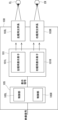
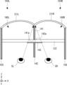
本実施の形態にかかるヘッドマウントディスプレイ、及びその表示方法について、図を参照して説明する。図1はヘッドマウントディスプレイ100の一部の構成を模式的に示す斜視図である。図2はヘッドマウントディスプレイ100の一部の機能ブロックを示す図である。図1、図2では、主として、ヘッドマウントディスプレイ100の画像表示に関する構成が示されている。図1では、ヘッドマウントディスプレイ100の内部構成が示されており、実際には、図1に示す各構成要素がカバーなどで覆われていてもよい。
Embodiment 1.
A head mounted display and a display method thereof according to the present embodiment will be described with reference to the drawings. FIG. 1 is a perspective view schematically showing the configuration of a part of the head-mounted display 100. FIG. 2 is a diagram showing some functional blocks of the head mounted display 100. 1 and 2 mainly show the configuration related to image display of the head mounted display 100. FIG. 1 shows the internal configuration of the head-mounted display 100, and in reality, each component shown in FIG. 1 may be covered with a cover or the like.
ヘッドマウントディスプレイ100は、ゲーム用、エンターテインメント用、産業用、医療用、フライトシミュレータ用などの様々な用途に適用可能である。ヘッドマウントディスプレイ100は、例えば、VR(Virtual Reality)ヘッドマウントディスプレイやAR(Augmented Reality)ヘッドマウントディスプレイやMR(Mixed Reality)ヘッドマウントディスプレイである。なお、本実施の形態では、ヘッドマウントディスプレイ100が、ARやMRに用いられるオプティカルシースルータイプのヘッドマウントディスプレイとなっているが、非透過型のヘッドマウントディスプレイであってもよい。
The head-mounted display 100 can be applied to various uses such as games, entertainment, industrial, medical, and flight simulators. The head mounted display 100 is, for example, a VR (Virtual Reality) head mounted display, an AR (Augmented Reality) head mounted display, or an MR (Mixed Reality) head mounted display. Note that in this embodiment, the head mounted display 100 is an optical see-through type head mounted display used for AR or MR, but it may be a non-transparent type head mounted display.
以下、説明の明確化のため、XYZ3次元直交座標系を用いて説明を行う。ユーザを基準として、前後方向(奥行方向)をZ方向、左右方向(水平方向)をX方向、上下方向(鉛直方向)をY方向とする。前方向が+Z方向、後ろ方向が-Z方向、右方向を+X方向、左方向を-X方向、上方向を+Y方向、下方向を-Y方向とする。
Hereinafter, for clarity of explanation, an explanation will be given using an XYZ three-dimensional orthogonal coordinate system. With the user as a reference, the front-rear direction (depth direction) is the Z direction, the left-right direction (horizontal direction) is the X direction, and the up-down direction (vertical direction) is the Y direction. The forward direction is the +Z direction, the back direction is the -Z direction, the right direction is the +X direction, the left direction is the -X direction, the upward direction is the +Y direction, and the downward direction is the -Y direction.
図示しないユーザが、ヘッドマウントディスプレイ100を装着している。ヘッドマウントディスプレイ100は、表示素子部101と、フレーム102と、左眼用光学系103Lと、右眼用光学系103Rと、制御部105を備えている。制御部105は、制御部105Lと制御部105Rとを備えている。
A user (not shown) is wearing a head-mounted display 100. The head mounted display 100 includes a display element section 101, a frame 102, a left eye optical system 103L, a right eye optical system 103R, and a control section 105. The control section 105 includes a control section 105L and a control section 105R.
フレーム102はゴーグル形状や眼鏡形状を有しており、図示しないヘッドバンドなどによりユーザの頭部に装着される。フレーム102には、表示素子部101、左眼用光学系103L、右眼用光学系103R、制御部105L、制御部105Rが取り付けられている。なお、図1では、両眼式のヘッドマウントディスプレイ100が図示されているが、眼鏡形状を有する非没入型ヘッドマウントディスプレイであってもよい。
The frame 102 has the shape of goggles or glasses, and is worn on the user's head with a headband (not shown) or the like. A display element section 101, a left eye optical system 103L, a right eye optical system 103R, a control section 105L, and a control section 105R are attached to the frame 102. Although FIG. 1 shows a binocular head-mounted display 100, it may be a non-immersive head-mounted display in the shape of glasses.
表示素子部101は、左眼用表示素子101Lと右眼用表示素子101Rを備えている。左眼用表示素子101Lは、左眼用の表示画像を生成する。右眼用表示素子101Rは、右眼用の表示画像を生成する。左眼用表示素子101L、及び右眼用表示素子101Rはそれぞれ液晶モニタや有機EL(Electro-Luminescence)モニタなどのフラットパネルディスプレイを備えている。左眼用表示素子101L、及び右眼用表示素子101Rは曲面形状を有するディスプレイでもよい。左眼用表示素子101Lと右眼用表示素子101Rは、それぞれアレイ状に配置された複数の画素を備えている。ここでアレイ状の配置とは、2次元状の配置だけでなく、ペンタイル配列などでもよい。左眼用表示素子101Lは右眼用表示素子101Rの左側(-X側)に配置されている。
The display element section 101 includes a left eye display element 101L and a right eye display element 101R. The left eye display element 101L generates a left eye display image. The right eye display element 101R generates a right eye display image. The left eye display element 101L and the right eye display element 101R each include a flat panel display such as a liquid crystal monitor or an organic EL (Electro-Luminescence) monitor. The left eye display element 101L and the right eye display element 101R may be displays having a curved shape. The left eye display element 101L and the right eye display element 101R each include a plurality of pixels arranged in an array. Here, the array arrangement may be not only a two-dimensional arrangement but also a pen tile arrangement. The left eye display element 101L is arranged on the left side (-X side) of the right eye display element 101R.
表示素子部101の上方(+Y側)には、制御部105が設けられている。制御部105には、外部からの映像信号、制御信号、電源が供給されている。例えば、HDMI(登録商標)などの有線接続、又はWiFi(登録商標)やBlueTooth(登録商標)等の無線接続によって、映像信号等が制御部105に入力される。ヘッドマウントディスプレイ100は、映像信号を生成する映像生成部(図示せず)を備えていてもよく、制御部105には、映像生成部が生成した映像信号等が入力されてもよい。
A control section 105 is provided above the display element section 101 (on the +Y side). The control unit 105 is supplied with external video signals, control signals, and power. For example, a video signal or the like is input to the control unit 105 through a wired connection such as HDMI (registered trademark) or a wireless connection such as WiFi (registered trademark) or BlueTooth (registered trademark). The head-mounted display 100 may include a video generation section (not shown) that generates a video signal, and the control section 105 may be input with a video signal generated by the video generation section.
制御部105L、制御部105RはCPU(Central Processing Unit)、及びメモリなどのハードウェア資源を備えており、メモリに格納されたコンピュータプログラムにしたがって動作する。さらに、制御部105L、制御部105Rはそれぞれ、ディスプレイの駆動回路等を備えている。制御部105Lは、映像信号、制御信号等に基づいて、左眼用画像の表示信号を生成して、左眼用表示素子101Lに出力する。これにより、左眼用表示素子101Lは、左眼用画像を表示するための表示光を出力する。制御部105Rは、映像信号、制御信号等に基づいて、右眼用画像の表示信号を生成して、右眼用表示素子101Rに出力する。これにより、右眼用表示素子101Rは、右眼用の表示画像を表示するための表示光を出力する。つまり、制御部105は表示信号を表示素子部101に出力する。
The control unit 105L and the control unit 105R include hardware resources such as a CPU (Central Processing Unit) and a memory, and operate according to a computer program stored in the memory. Furthermore, the control unit 105L and the control unit 105R each include a display drive circuit and the like. The control unit 105L generates a display signal for a left eye image based on the video signal, control signal, etc., and outputs it to the left eye display element 101L. Thereby, the left eye display element 101L outputs display light for displaying the left eye image. The control unit 105R generates a display signal for a right eye image based on the video signal, control signal, etc., and outputs it to the right eye display element 101R. Thereby, the right eye display element 101R outputs display light for displaying a right eye display image. That is, the control section 105 outputs a display signal to the display element section 101.
なお、表示素子部101は、左眼用表示素子101Lと右眼用表示素子101Rを別々の表示素子とする構成に限らず、単一の表示素子とする構成としてもよい。単一の表示素子が、左眼用の表示画像と右眼用の表示画像とを生成してもよい。この場合、表示素子部101は、ディスプレイの表示領域の片側の一部を用いて、左眼用画像を生成し、反対側の一部を用いて、右眼用画像を生成する。
Note that the display element section 101 is not limited to the configuration in which the left eye display element 101L and the right eye display element 101R are separate display elements, but may be configured as a single display element. A single display element may generate a left eye display image and a right eye display image. In this case, the display element unit 101 uses a part of one side of the display area of the display to generate a left-eye image, and uses a part of the opposite side to generate a right-eye image.
表示素子部101、制御部105等の一部又は全部は、フレーム102に固定されている構成に限らず、フレーム102に対して脱着可能に設けられていてもよい。例えば、スマートフォン又はタブレットコンピュータ等をフレーム102に対して取り付けることで、表示素子部101、制御部105等を実現してもよい。この場合、スマートフォン等にヘッドマウントディスプレイ用の表示画像を生成するアプリケーションプログラム(アプリ)を予めインストールしておけばよい。
Some or all of the display element section 101, the control section 105, etc. are not limited to the configuration in which they are fixed to the frame 102, and may be provided in a detachable manner with respect to the frame 102. For example, the display element section 101, the control section 105, etc. may be realized by attaching a smartphone, a tablet computer, or the like to the frame 102. In this case, an application program (app) that generates a display image for a head-mounted display may be installed in advance on a smartphone or the like.
左眼用光学系103Lは、左眼用表示素子101Lが出力した表示光を、左眼用画像としてユーザの左眼ELに導く。右眼用光学系103Rは、右眼用表示素子101Rが出力した表示光を、右眼用画像としてユーザの右眼ERに導く。左眼用光学系103Lは右眼用光学系103Rの左側(-X側)に配置されている。左眼用光学系103Lは、ユーザの左眼ELの前方(+Z方向)に配置されている。右眼用光学系103Rは、ユーザの右眼ERの前方(+Z方向)に配置されている。ユーザは、表示素子部101が生成した表示画像の虚像を正面前方(+Z方向)に視認することができる。
The left eye optical system 103L guides the display light output from the left eye display element 101L to the user's left eye EL as a left eye image. The right eye optical system 103R guides the display light output from the right eye display element 101R to the user's right eye ER as a right eye image. The left eye optical system 103L is arranged on the left side (-X side) of the right eye optical system 103R. The left eye optical system 103L is arranged in front of the user's left eye EL (in the +Z direction). The right eye optical system 103R is arranged in front of the user's right eye ER (in the +Z direction). The user can visually recognize the virtual image of the display image generated by the display element unit 101 in front (+Z direction).
上記の通り、本実施の形態にかかるヘッドマウントディスプレイ100は、半透過型又は非透過型のヘッドマウントディスプレイのいずれにも可能である。なお、ここではヘッドマウントディスプレイ100が、半透過型のヘッドマウントディスプレイであるとして説明を行う。従って、左眼用光学系103L、及び右眼用光学系103Rは、後述するコンバイナを備えている。半透過型のヘッドマウントディスプレイ100では、表示素子部101からの表示光と、外光とが、左眼EL及び右眼ERに入射する。よって、ユーザは、前方(+Z方向)の景色に表示画像が重畳した重畳画像を視認することができる。
As described above, the head mounted display 100 according to this embodiment can be either a transflective type or a non-transparent type head mounted display. Note that the description here assumes that the head-mounted display 100 is a transflective head-mounted display. Therefore, the left eye optical system 103L and the right eye optical system 103R include a combiner, which will be described later. In the transflective head-mounted display 100, display light from the display element section 101 and external light enter the left eye EL and the right eye ER. Therefore, the user can visually recognize a superimposed image in which the display image is superimposed on the scenery in front (+Z direction).
以下、左眼用光学系103Lと右眼用光学系103R(以下、まとめて単に光学系と称する)の例について説明する。図3は、光学系を模式的に示す側面図である。なお、左眼用光学系103Lと右眼用光学系103Rとは同様の構成となっているため、主として左眼用光学系103Lに対して説明を行う。
Examples of the left eye optical system 103L and the right eye optical system 103R (hereinafter simply referred to as optical systems) will be described below. FIG. 3 is a side view schematically showing the optical system. Note that since the left eye optical system 103L and the right eye optical system 103R have similar configurations, the left eye optical system 103L will be mainly described.
左眼用光学系103Lは、コンバイナ121Lと、ビームスプリッタ122と、遮光部150Lと、を備えている。右眼用光学系103Rは、コンバイナ121Rと、ビームスプリッタ122と、遮光部150Rと、を備えている。コンバイナ121L、121R、ビームスプリッタ122、及び遮光部150L、150Rは、図1で示したフレーム102に固定されている。
The left eye optical system 103L includes a combiner 121L, a beam splitter 122, and a light shielding section 150L. The right eye optical system 103R includes a combiner 121R, a beam splitter 122, and a light shielding section 150R. The combiners 121L and 121R, the beam splitter 122, and the light shielding parts 150L and 150R are fixed to the frame 102 shown in FIG. 1.
ビームスプリッタ122は、左眼用光学系103Lと右眼用光学系103Rとで共通となっている。つまり、左眼用光学系103Lと右眼用光学系103Rとで、単一のビームスプリッタ122が共用されている。
The beam splitter 122 is common to the left eye optical system 103L and the right eye optical system 103R. That is, the single beam splitter 122 is shared by the left eye optical system 103L and the right eye optical system 103R.
コンバイナ121Lは凹面鏡となっており、ビームスプリッタ122は平面鏡となっている。コンバイナ121L、及びビームスプリッタ122はハーフミラー等のビームスプリッタであり、入射光の一部を反射して、一部を透過する。コンバイナ121Lの反射の比率と透過の比率とが等しいとすると、コンバイナ121Lは、入射光のほぼ半分の光量を透過し、残りの半分を反射する。同様に、ビームスプリッタ122の反射の比率と透過の比率とが等しいとすると、ビームスプリッタ122は、入射光のほぼ半分の光量を透過し、残りの半分を反射する。コンバイナ121L及びビームスプリッタ122は、反射の比率を増やし透過の比率を減らしてもよいし、反射の比率を減らし透過の比率を増やしてもよい。
The combiner 121L is a concave mirror, and the beam splitter 122 is a plane mirror. The combiner 121L and the beam splitter 122 are beam splitters such as half mirrors, and reflect part of the incident light and transmit part of it. Assuming that the reflection ratio and the transmission ratio of the combiner 121L are equal, the combiner 121L transmits approximately half the amount of incident light and reflects the remaining half. Similarly, assuming that the reflection ratio and the transmission ratio of the beam splitter 122 are equal, the beam splitter 122 transmits approximately half of the amount of incident light and reflects the remaining half. The combiner 121L and the beam splitter 122 may increase the reflection ratio and reduce the transmission ratio, or may reduce the reflection ratio and increase the transmission ratio.
コンバイナ121L、及びビームスプリッタ122はユーザの左眼ELの正面前方(+Z方向)に配置されている。また、コンバイナ121Lは、ビームスプリッタ122の前方(+Z方向)に配置されている。
The combiner 121L and the beam splitter 122 are arranged in front of the user's left eye EL (in the +Z direction). Further, the combiner 121L is arranged in front of the beam splitter 122 (in the +Z direction).
ビームスプリッタ122の上方(+Y方向)には、左眼用表示素子101Lが配置されている。左眼用表示素子101Lは表示画像を形成するための表示光PL11を出射する。つまり、左眼用表示素子101Lは、左眼ELの前方斜め上に配置されている。
A left eye display element 101L is arranged above the beam splitter 122 (in the +Y direction). The left eye display element 101L emits display light PL11 for forming a display image. In other words, the left eye display element 101L is arranged diagonally above and in front of the left eye EL.
遮光部150Lは、ビームスプリッタ122の下方(-Y方向)に配置されている。つまり、遮光部150Lは、左眼ELの前方斜め下に配置されている。遮光部150Lは、前方斜め下の視界を遮るために設けられている。遮光部150Lは光を吸収する黒色材料などで形成されている。遮光部150Lの代わりに、前方斜め下を視認するための下部窓を設けてもよい。
The light shielding section 150L is arranged below the beam splitter 122 (in the -Y direction). That is, the light shielding part 150L is arranged diagonally below the front of the left eye EL. The light shielding portion 150L is provided to block the view diagonally below the front. The light shielding portion 150L is made of a black material that absorbs light. Instead of the light shielding part 150L, a lower window for viewing diagonally downward in front may be provided.
左眼用表示素子101Lからの表示光PL11について説明する。左眼用表示素子101Lの表示面は、下方(-Y方向)に面している。したがって、左眼用表示素子101Lからの表示光PL11は、下方(-Y方向)に出射される。左眼用表示素子101Lの下方(-Y方向)には、ビームスプリッタ122が傾斜して配置されている。左眼用表示素子101Lからの表示光PL11は、ビームスプリッタ122に入射する。ビームスプリッタ122は、表示光PL11の一部を反射する。また、ビームスプリッタ122を透過した残りの表示光PL11は、遮光部150Lで吸収される。
The display light PL11 from the left eye display element 101L will be explained. The display surface of the left eye display element 101L faces downward (-Y direction). Therefore, the display light PL11 from the left eye display element 101L is emitted downward (in the -Y direction). A beam splitter 122 is arranged at an angle below the left eye display element 101L (in the −Y direction). Display light PL11 from left eye display element 101L enters beam splitter 122. Beam splitter 122 reflects a portion of display light PL11. Further, the remaining display light PL11 that has passed through the beam splitter 122 is absorbed by the light shielding section 150L.
ビームスプリッタ122で反射した表示光PL11は、前方(+Z方向)に反射される。そして、表示光PL11は、コンバイナ121Lに入射する。コンバイナ121Lは、後方(-Z方向)に表示光PL11の一部を反射する。コンバイナ121Lで反射された表示光PL11を表示光PL12とする。さらに、コンバイナ121Lは凹面鏡であり、表示光PL12を左眼ELに向けて集光するように、表示光PL11を反射する。コンバイナ121Lで反射された表示光PL12は、ビームスプリッタ122に入射する。ビームスプリッタ122は、表示光PL12の一部を透過する。
Display light PL11 reflected by beam splitter 122 is reflected forward (+Z direction). The display light PL11 then enters the combiner 121L. The combiner 121L reflects a portion of the display light PL11 backward (in the -Z direction). The display light PL11 reflected by the combiner 121L is referred to as display light PL12. Furthermore, the combiner 121L is a concave mirror, and reflects the display light PL11 so as to condense the display light PL12 toward the left eye EL. Display light PL12 reflected by combiner 121L enters beam splitter 122. Beam splitter 122 transmits a portion of display light PL12.
ビームスプリッタ122を透過した表示光PL12は、左眼ELに入射する。このように、左眼用光学系103Lが、左眼用表示素子101Lからの表示光PL11を、ユーザの左眼ELに導く。光学系により、ユーザの前方(+Z方向)に虚像を表示させることができる。また、コンバイナ121Lとして凹面鏡を用いているため、表示画像が拡大して表示される。
Display light PL12 transmitted through beam splitter 122 enters left eye EL. In this way, the left eye optical system 103L guides the display light PL11 from the left eye display element 101L to the user's left eye EL. The optical system allows a virtual image to be displayed in front of the user (in the +Z direction). Further, since a concave mirror is used as the combiner 121L, the displayed image is displayed in an enlarged manner.
次に、ユーザの前方(+Z方向)からの外光PL21について説明する。外光PL21の一部は、コンバイナ121Lを透過する。コンバイナ121Lを透過した外光PL21は、ビームスプリッタ122に入射する。ビームスプリッタ122は、外光PL21の一部を透過する。ビームスプリッタ122を透過した外光PL21は、左眼ELに入射する。
Next, external light PL21 from in front of the user (+Z direction) will be explained. A portion of the external light PL21 is transmitted through the combiner 121L. The external light PL21 that has passed through the combiner 121L is incident on the beam splitter 122. Beam splitter 122 transmits a portion of external light PL21. The external light PL21 that has passed through the beam splitter 122 is incident on the left eye EL.
ヘッドマウントディスプレイ100が半透過型であるため、コンバイナ121Lは、前方(+Z方向)からの外光PL21と左眼用表示素子101Lからの表示光PL11を合成する。ユーザの前方(+Z方向)にコンバイナ121Lを設けることで、ヘッドマウントディスプレイ100を光学シースルー方式とすることができる。ユーザの前方(+Z方向)の景色に、表示画像が重畳される。つまり、ユーザは、表示画像が重畳された景色を視認することができる。
Since the head mounted display 100 is of a transflective type, the combiner 121L combines external light PL21 from the front (+Z direction) and display light PL11 from the left eye display element 101L. By providing the combiner 121L in front of the user (in the +Z direction), the head mounted display 100 can be of an optical see-through type. The display image is superimposed on the scenery in front of the user (in the +Z direction). In other words, the user can visually recognize the scenery on which the display image is superimposed.
右眼用光学系103Rについては、左眼用光学系103Lと同様になっている。さらに、左眼用光学系103Lと右眼用光学系103Rとでビームスプリッタ122が共通となっている。つまり、一体的に形成された一枚のビームスプリッタ122が、左眼用光学系103Lの表示光PL11、PL12と右眼用光学系103Rの表示光PR11、PR12との光路に配置されている。
The right eye optical system 103R is similar to the left eye optical system 103L. Furthermore, the beam splitter 122 is common to the left eye optical system 103L and the right eye optical system 103R. In other words, one integrally formed beam splitter 122 is placed in the optical path of the display lights PL11 and PL12 of the left eye optical system 103L and the display lights PR11 and PR12 of the right eye optical system 103R.
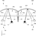
左眼用光学系103Lと右眼用光学系103Rとがビームスプリッタ122を共用することで、アライメント調整を容易に行うことができる。換言すると、左眼用光学系103Lと右眼用光学系103Rとが別々のビームスプリッタを用いている場合、高精度のアライメント調整が要求される。以下、左眼用光学系103Lと右眼用光学系103Rとでビームスプリッタ122が別々に設けられている構成について、図4を用いて説明する。
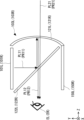
Since the left eye optical system 103L and the right eye optical system 103R share the beam splitter 122, alignment adjustment can be easily performed. In other words, when the left eye optical system 103L and the right eye optical system 103R use separate beam splitters, highly accurate alignment adjustment is required. Hereinafter, a configuration in which the beam splitter 122 is separately provided in the left eye optical system 103L and the right eye optical system 103R will be described using FIG. 4.
図4では、左眼用光学系103Lと右眼用光学系103Rとでビームスプリッタ122が別々に設けられている。左眼用光学系103Lのビームスプリッタ122をビームスプリッタ122Lとし、左眼用光学系103Lのビームスプリッタ122をビームスプリッタ122Rとして示す。ビームスプリッタ122Lとビームスプリッタ122Rとは別個の光学部品となっている。ビームスプリッタ122Lとビームスプリッタ122Rとをそれぞれフレーム102などに取り付ける場合、取付誤差が生じることがある。
In FIG. 4, beam splitters 122 are separately provided for the left eye optical system 103L and the right eye optical system 103R. The beam splitter 122 of the left eye optical system 103L is shown as a beam splitter 122L, and the beam splitter 122 of the left eye optical system 103L is shown as a beam splitter 122R. Beam splitter 122L and beam splitter 122R are separate optical components. When attaching the beam splitter 122L and the beam splitter 122R to the frame 102 or the like, an attachment error may occur.
図4は、取付誤差等によって、ビームスプリッタ122Lとビームスプリッタ122Rの設置角度がずれた状態を示している。ビームスプリッタ122Lとビームスプリッタ122Rの設置角度が異なる場合、表示光PL11、表示光PR11の反射方向にずれが生じる。ここで、ビームスプリッタ122Lでコンバイナ121Lの方向に反射した表示光PL11を表示光PL13とし、ビームスプリッタ122Rでコンバイナ121Rの方向に反射した表示光PR11を表示光PR13とする。取付誤差等によって、表示光PL13の伝播方向が表示光PR13の伝播方向と平行にならなくなってしまう。
FIG. 4 shows a state in which the installation angles of the beam splitter 122L and the beam splitter 122R are deviated due to an installation error or the like. When the installation angles of the beam splitter 122L and the beam splitter 122R are different, a shift occurs in the reflection direction of the display light PL11 and the display light PR11. Here, the display light PL11 reflected in the direction of the combiner 121L by the beam splitter 122L is referred to as display light PL13, and the display light PR11 reflected in the direction of the combiner 121R by the beam splitter 122R is referred to as display light PR13. Due to mounting errors and the like, the propagation direction of display light PL13 is no longer parallel to the propagation direction of display light PR13.
この場合、ユーザが視認する左眼用表示画像と右眼用表示画像の間で位置ずれが生じてしまう。図4では、ビームスプリッタ122Lとビームスプリッタ122Rとで、X軸周りの角度が異なっている。図4では、左眼ELから見た左眼用表示画像の中心の方向を中心軸OXLとし、右眼ERから見た右眼用表示画像の中心の方向を中心軸OXRとして示している。取付誤差によって、中心軸OXLと中心軸OXRとが平行とならないと、左眼用表示画像と右眼用表示画像が上下方向(Z方向)にずれて視認されてしまうという。ユーザが右眼用表示画像を左眼用表示画像よりも上方(+Z方向)に視認してしまう。
In this case, a positional shift occurs between the left eye display image and the right eye display image visually recognized by the user. In FIG. 4, the angles around the X axis are different between the beam splitter 122L and the beam splitter 122R. In FIG. 4, the direction of the center of the left-eye display image as seen from the left eye EL is shown as a central axis OXL, and the direction of the center of the right-eye display image as seen from the right eye ER is shown as a central axis OXR. If the central axis OXL and the central axis OXR are not parallel to each other due to installation error, the left eye display image and the right eye display image will be viewed as being shifted in the vertical direction (Z direction). The user ends up viewing the right-eye display image above (+Z direction) than the left-eye display image.
特に、オプティカルシースルーとするために、コンバイナ121L、121Rを用いた構成では、コンバイナ121L、121Rを通じて、ユーザが外界の景色や物体を見ることができる。この場合、ユーザが外界に焦点を合わせると左右の表示画像がずれた状態となり、ユーザが2重像のように視認してしまう。ヘッドマウントディスプレイ100の軽量化や低コスト化のため、樹脂でフレーム102やビームスプリッタ122を作製する場合、2つのビームスプリッタ122L,122Rを高精度にアライメント調整することが困難である。
In particular, in a configuration using combiners 121L and 121R for optical see-through, the user can see scenery and objects in the outside world through the combiners 121L and 121R. In this case, when the user focuses on the outside world, the left and right display images are shifted, and the user sees what appears to be a double image. When the frame 102 and beam splitter 122 are made of resin in order to reduce the weight and cost of the head mounted display 100, it is difficult to adjust the alignment of the two beam splitters 122L and 122R with high precision.
これに対して、図3では、左眼用光学系103Lと右眼用光学系103Rとで共通のビームスプリッタ122が用いられている。よって、ビームスプリッタ122の取付誤差が生じない。ユーザに視認される表示画像の位置ずれを抑制することができ、高い表示品質を得ることができる。ビームスプリッタ122を樹脂製としても高精度にアライメント調整することができるため、ヘッドマウントディスプレイ100の軽量化を図ることが可能となる。
In contrast, in FIG. 3, a common beam splitter 122 is used for the left eye optical system 103L and the right eye optical system 103R. Therefore, no installation error of the beam splitter 122 occurs. It is possible to suppress the positional shift of the displayed image visually recognized by the user, and it is possible to obtain high display quality. Even if the beam splitter 122 is made of resin, the alignment can be adjusted with high precision, so it is possible to reduce the weight of the head mounted display 100.
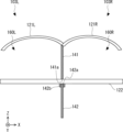
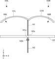
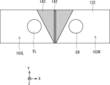
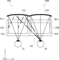
次に、クロストークを抑制するための構成について、図5、及び図6を用いて説明する。図5は、光学系を模式的に示す上面図であり、図6は側面断面図である。図5、及び図6に示すように、左眼用光学系103Lと右眼用光学系103Rとの間には、仕切り部140が設けられている。またビームスプリッタ122は、左前方空間160Lから右前方空間160Rに渡って配置されている。
Next, a configuration for suppressing crosstalk will be described using FIGS. 5 and 6. FIG. 5 is a top view schematically showing the optical system, and FIG. 6 is a side sectional view. As shown in FIGS. 5 and 6, a partition portion 140 is provided between the left eye optical system 103L and the right eye optical system 103R. Furthermore, the beam splitter 122 is arranged from the left front space 160L to the right front space 160R.
仕切り部140は、左眼ELの前方(+Z方向)の空間(以下、左前方空間160Lとする)と右眼ERの前方(+Z方向)の空間(以下、右前方空間160Rとする)との間に配置されている。左前方空間160Lと右前方空間160Rは、仕切り部140によって仕切られている。仕切り部140は、X方向における左前方空間160Lと右前方空間160Rとの境界を規定する。
The partition part 140 separates a space in front of the left eye EL (in the +Z direction) (hereinafter referred to as a left front space 160L) and a space in front of the right eye ER (in the +Z direction) (hereinafter referred to as a right front space 160R). placed in between. The left front space 160L and the right front space 160R are partitioned by a partition portion 140. The partition portion 140 defines a boundary between the left front space 160L and the right front space 160R in the X direction.
なお、左前方空間160Lは、コンバイナ121L、左眼用表示素子101L、遮光部150L、仕切り部140、フレーム102(図1を合わせて参照)、及びユーザの顔によって規定される空間となる。つまり、左前方空間160Lの前方(+Z方向)は、コンバイナ121Lに面しており、後方(-Z方向)は、ユーザの顔に面している。左前方空間160Lの上方(+Y方向)は、左眼用表示素子101Lに面しており、下方(-Y方向)は遮光部150Lに面している。左前方空間160Lの右側(+X方向)は、仕切り部140に面しており、左側(-X方向)はフレーム102に面している。
Note that the left front space 160L is a space defined by the combiner 121L, the left eye display element 101L, the light shielding section 150L, the partition section 140, the frame 102 (see also FIG. 1), and the user's face. That is, the front (+Z direction) of the left front space 160L faces the combiner 121L, and the rear (−Z direction) faces the user's face. The upper side (+Y direction) of the left front space 160L faces the left eye display element 101L, and the lower side (-Y direction) faces the light shielding part 150L. The right side (+X direction) of the left front space 160L faces the partition portion 140, and the left side (−X direction) faces the frame 102.
同様に、右前方空間160Rは、コンバイナ121R、右眼用表示素子101R、遮光部150R、仕切り部140、フレーム102(図1を合わせて参照)、及びユーザの顔によって規定される空間となる。つまり、右前方空間160Rの前方(+Z方向)は、コンバイナ121Rに面しており、後方(-Z方向)は、ユーザの顔に面している。右前方空間160Rの上方(+Y方向)は、右眼用表示素子101Rに面しており、下方(-Y方向)は遮光部150Rに面している。右前方空間160Rの右側(+X方向)は、フレーム102に面しており、左側(-X方向)は仕切り部140に面している。
Similarly, the right front space 160R is a space defined by the combiner 121R, the right eye display element 101R, the light shielding section 150R, the partition section 140, the frame 102 (see also FIG. 1), and the user's face. That is, the front (+Z direction) of the right front space 160R faces the combiner 121R, and the rear (−Z direction) faces the user's face. The upper part (+Y direction) of the right front space 160R faces the right eye display element 101R, and the lower part (-Y direction) faces the light shielding part 150R. The right side (+X direction) of the right front space 160R faces the frame 102, and the left side (−X direction) faces the partition portion 140.
図6に示すように、仕切り部140が仕切り板141、及び仕切り板142を備えている。仕切り部140が2枚の仕切り板141,142で構成されている。仕切り板141は、ビームスプリッタ122よりも前方(+Z方向)に配置されている。仕切り板142は、ビームスプリッタ122よりも後方(-Z方向)に配置されている。仕切り板141は、ビームスプリッタ122と接触していてもよく、ビームスプリッタ122と接触しなくてもよい。仕切り板142は、ビームスプリッタ122と接触していてもよく、ビームスプリッタ122と接触しなくてもよい。仕切り板141と仕切り板142は、少なくともビームスプリッタ122の厚さ分だけ離れて配置されている。
As shown in FIG. 6, the partition section 140 includes a partition plate 141 and a partition plate 142. The partition section 140 is composed of two partition plates 141 and 142. The partition plate 141 is arranged ahead of the beam splitter 122 (in the +Z direction). The partition plate 142 is arranged behind the beam splitter 122 (in the -Z direction). The partition plate 141 may or may not be in contact with the beam splitter 122. The partition plate 142 may or may not be in contact with the beam splitter 122. The partition plate 141 and the partition plate 142 are spaced apart by at least the thickness of the beam splitter 122.
仕切り板141、及び仕切り板142はそれぞれ可視光を拡散反射する拡散反射板である。拡散反射とは、光の反射のうち鏡面反射を除いた拡散的な反射成分を意味する。仕切り板141、及び仕切り板142は入射した外光、及び表示光を様々な方向に拡散して反射する。なお、仕切り部140は、左前方空間160Lと右前方空間160Rとを完全に仕切っていなくてもよい。つまり、左前方空間160Lと右前方空間160Rとは一部が繋がっていてもよい。
The partition plate 141 and the partition plate 142 are each a diffuse reflection plate that diffusely reflects visible light. Diffuse reflection means a diffuse reflection component of light reflection excluding specular reflection. The partition plate 141 and the partition plate 142 diffuse and reflect incident external light and display light in various directions. Note that the partition portion 140 does not need to completely partition the left front space 160L and the right front space 160R. In other words, the left front space 160L and the right front space 160R may be partially connected.
仕切り部140は、左眼用表示素子101Lからの表示光PL11、PL12が右眼ERに入射するのを遮る。また、仕切り部140は、右眼用表示素子101Rからの表示光PR11、及びコンバイナ121Rで反射された表示光PR11である表示光PR12が左眼ELに入射するのを遮る。つまり、仕切り部140は、図25に示したクロストーク光PCTを遮光する。これにより、クロストークを抑制することができ、表示品質を向上することができる。
The partition portion 140 blocks display lights PL11 and PL12 from the left eye display element 101L from entering the right eye ER. Furthermore, the partition section 140 blocks the display light PR11 from the right eye display element 101R and the display light PR12, which is the display light PR11 reflected by the combiner 121R, from entering the left eye EL. In other words, the partition section 140 blocks the crosstalk light PCT shown in FIG. 25. Thereby, crosstalk can be suppressed and display quality can be improved.
また、仕切り部140の仕切り板141、及び仕切り板142は拡散反射板であるため、仕切り部140に入射した光の一部が左眼EL又は右眼ERに到達する。例えば、コンバイナ121Lを通過した外光PL21の一部は、仕切り部140で拡散反射して、左眼ELに入射する。また、左眼用表示素子101Lからの表示光PL11、PL12の一部は、仕切り部140で拡散反射して、左眼ELに入射する。コンバイナ121Rを通過した外光PR21の一部は、仕切り部140で拡散反射して、右眼ERに入射する。また、右眼用表示素子101Rからの表示光PR11、PR12の一部は、仕切り部140で拡散反射して、右眼ERに入射する。
Moreover, since the partition plate 141 and the partition plate 142 of the partition part 140 are diffuse reflection plates, a part of the light incident on the partition part 140 reaches the left eye EL or the right eye ER. For example, a portion of the external light PL21 that has passed through the combiner 121L is diffusely reflected by the partition 140 and enters the left eye EL. Further, a portion of the display lights PL11 and PL12 from the left eye display element 101L is diffusely reflected by the partition portion 140 and enters the left eye EL. A part of the external light PR21 that has passed through the combiner 121R is diffusely reflected by the partition 140 and enters the right eye ER. Further, a portion of the display lights PR11 and PR12 from the right eye display element 101R is diffusely reflected by the partition portion 140 and enters the right eye ER.
よって、本実施の形態では仕切り部140が、非拡散反射板であった場合と比較して、ユーザにより仕切り部140が黒い影のように視認されることを防ぐことができる。換言すると、仕切り部140が目立たなくなるように、仕切り部140が光の一部を拡散反射する。なお、非拡散反射板とは、例えば黒色に着色された樹脂板のことである。
Therefore, in this embodiment, compared to the case where the partition part 140 is a non-diffuse reflector, it is possible to prevent the partition part 140 from being visually recognized by the user as a black shadow. In other words, the partition section 140 diffusely reflects a portion of the light so that the partition section 140 becomes less noticeable. Note that the non-diffuse reflecting plate is, for example, a resin plate colored black.
仕切り部140が明るくなりすぎたり、暗くなりすぎたりして目立たないように、仕切り部140の拡散反射率を調整すればよい。拡散反射率とは、入射光量に対する拡散反射の光量の比率のことであり、色の明るさを表す。拡散反射率は、仕切り部140を着色する色、及び仕切り部140の表面の加工により調整することができる。仕切り部140の拡散反射率は、明るくなりすぎる0%近傍でなく、かつ、暗くなりすぎる100%近傍でない範囲であるとよい。これにより、ユーザが自然に表示画像を視認することができるため、表示品質を向上することができる。
The diffuse reflectance of the partition section 140 may be adjusted so that the partition section 140 does not become too bright or too dark and becomes inconspicuous. Diffuse reflectance is the ratio of the amount of diffusely reflected light to the amount of incident light, and represents the brightness of color. The diffuse reflectance can be adjusted by changing the color of the partition 140 and processing the surface of the partition 140. The diffuse reflectance of the partition portion 140 is preferably in a range that is not near 0%, which is too bright, and not near 100%, which is too dark. This allows the user to view the displayed image naturally, thereby improving the display quality.
仕切り部140を適切な拡散反射率にして目立たなくするために例えば、仕切り部140はグレーなどに着色された樹脂板を用いることができる。グレーとは白と黒との混合色である無彩色のうち、混合比が白100パーセントである白色と混合比が黒100パーセントである黒色を除いた色のことである。グレーとは混合比が白1パーセントかつ黒99パーセントの色も含み、また白99パーセントかつ黒1パーセントの色も含む。つまり仕切り部140は、白色でも、黒色でもない色に着色されている。
In order to make the partition part 140 have an appropriate diffuse reflectance so as to make it inconspicuous, for example, the partition part 140 can be made of a resin plate colored gray or the like. Gray is a color that is a mixture of white and black, excluding white, which has a mixing ratio of 100% white, and black, which has a mixing ratio of 100% black. Gray includes colors with a mixing ratio of 1% white and 99% black, and also includes colors with a mixing ratio of 99% white and 1% black. In other words, the partition portion 140 is colored neither white nor black.
また、仕切り部140の表面に拡散反射加工を施して形成することにより、仕切り部140を適切な拡散反射率にして目立たなくすることができる。拡散反射加工とは、例えば樹脂表面をサンドペーパーなどで擦って微細な凸凹に荒らすことである。ここで仕切り部140の表面とは、左前方空間160Lに臨む面、及び、右前方空間160Rに臨む面のことである。つまり、仕切り板141及び仕切り板142の表面とは、左前方空間160Lに臨む面と、右前方空間160Rに臨む面のことである。仕切り板141、及び仕切り板142の表面に拡散反射加工を施すことができる。
Moreover, by performing diffuse reflection processing on the surface of the partition part 140, the partition part 140 can be made to have an appropriate diffuse reflectance and be made inconspicuous. Diffuse reflection processing means, for example, rubbing the resin surface with sandpaper or the like to roughen it into fine irregularities. Here, the surface of the partition portion 140 refers to a surface facing the left front space 160L and a surface facing the right front space 160R. That is, the surfaces of the partition plate 141 and the partition plate 142 refer to a surface facing the left front space 160L and a surface facing the right front space 160R. Diffuse reflection processing can be applied to the surfaces of the partition plates 141 and 142.
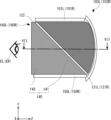
仕切り部140の明るさ暗さに関わらず、仕切り部140を肌色などのユーザの皮膚の色とほぼ同色にして目立たなくしてもよい。ユーザの皮膚の色とは一般に肌色と認識され得る色全般を指し、人種の肌の色により適宜変更することができる。ユーザの皮膚の色は例えば、CIE色度図上で0.375≦x≦0.400かつ0.340≦y≦0.360の範囲にある色としてもよい。ユーザがコーカソイド系の人種である場合の皮膚の色は、CIE色度図上で0.375≦x≦0.385かつ0.340≦y≦0.345の範囲にある色としてもよい。ユーザがモンゴロイド系又はネグロイド系の人種である場合の皮膚の色は、CIE色度図上で0.390≦x≦0.400かつ0.350≦y≦0.360の範囲にある色としてもよい。仕切り部140を皮膚の色と同系色にすることで、仕切り部140が鼻と融合され、鼻の一部のように視認されるため、表示品質を向上することができる。
Regardless of the brightness or darkness of the partitioning part 140, the partitioning part 140 may be made to be approximately the same color as the user's skin, such as skin color, to make it less noticeable. The user's skin color generally refers to any color that can be recognized as skin color, and can be changed as appropriate depending on the skin color of the user's race. The user's skin color may be, for example, a color in the range of 0.375≦x≦0.400 and 0.340≦y≦0.360 on the CIE chromaticity diagram. If the user is Caucasian, the skin color may be in the range of 0.375≦x≦0.385 and 0.340≦y≦0.345 on the CIE chromaticity diagram. If the user is a Mongoloid or Negroid race, the skin color is within the range of 0.390≦x≦0.400 and 0.350≦y≦0.360 on the CIE chromaticity diagram. Good too. By making the partition part 140 a similar color to the skin color, the partition part 140 is fused with the nose and visually recognized as part of the nose, thereby improving display quality.
仕切り部140が拡散反射板であることにより、仕切り部140が強調されることなく、ユーザが表示画像を視認することができる。これにより、表示品質を高くすることができる。また、仕切り部140に入射した表示光も拡散反射されるため、仕切り部140で反射した表示光により表示画像の一部が形成されることを防ぐことができる。これにより、表示品質を高くすることができる。
Since the partition section 140 is a diffuse reflection plate, the user can visually recognize the displayed image without the partition section 140 being emphasized. Thereby, display quality can be improved. Furthermore, since the display light incident on the partition section 140 is also diffusely reflected, it is possible to prevent a portion of the display image from being formed by the display light reflected on the partition section 140. Thereby, display quality can be improved.
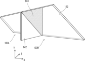
なお、左右方向(X方向)を厚さ方向とする薄板により仕切り板141、及び仕切り板142を形成すればよい。YZ平面における仕切り板141、及び仕切り板142の形状は、左前方空間160Lと右前方空間160Rの形状に応じて決めればよい。なお、仕切り板141となる拡散反射板の端辺は、表示素子部101と、コンバイナ121L、121Rと、ビームスプリッタ122に沿った形状とすればよい。仕切り板142となる拡散反射板の短辺は、ビームスプリッタ122と、遮光部150L、150Rとに沿った形状とすればよい。図6に示すように、仕切り板141の前方(+Z方向)側の端辺は、コンバイナ121L、121Rの湾曲に沿って形成されている。つまり、YZ平面において、仕切り板141の前方(+Z方向)側の端辺は、円弧状に形成されている。このようにすることで、左前方空間160Lと右前方空間160Rとを適切に仕切ることができるため、クロストークを効果的に抑制することが可能となる。
Note that the partition plates 141 and 142 may be formed of thin plates whose thickness direction is the left-right direction (X direction). The shapes of the partition plate 141 and the partition plate 142 in the YZ plane may be determined according to the shapes of the left front space 160L and the right front space 160R. Note that the edges of the diffuse reflection plate serving as the partition plate 141 may have a shape along the display element section 101, the combiners 121L and 121R, and the beam splitter 122. The short side of the diffuse reflection plate serving as the partition plate 142 may have a shape along the beam splitter 122 and the light shielding parts 150L and 150R. As shown in FIG. 6, the front (+Z direction) side edge of the partition plate 141 is formed along the curves of the combiners 121L and 121R. That is, in the YZ plane, the front (+Z direction) side edge of the partition plate 141 is formed in an arc shape. By doing so, the left front space 160L and the right front space 160R can be appropriately partitioned, so that crosstalk can be effectively suppressed.
次に、仕切り板141と仕切り板142の形状について詳細に説明する。図7は、図6のVII―VII断面での構成を模式的に示す図である。以下、X方向における仕切り板141、142の大きさを仕切り板141、142の厚さとして説明する。
Next, the shapes of the partition plates 141 and 142 will be explained in detail. FIG. 7 is a diagram schematically showing the configuration taken along the line VII-VII in FIG. 6. Hereinafter, the size of the partition plates 141 and 142 in the X direction will be described as the thickness of the partition plates 141 and 142.
仕切り板141は、一定の厚さとなっている。つまり、X方向における仕切り板141の大きさはZ方向の位置に関わらず一定になっている。なお、仕切り板141のビームスプリッタ122側の端部を端部141aとする。
The partition plate 141 has a constant thickness. In other words, the size of the partition plate 141 in the X direction is constant regardless of its position in the Z direction. Note that the end of the partition plate 141 on the beam splitter 122 side is referred to as an end 141a.
仕切り板142は、テーパ形状となっており、-Z側の端部から+Z方向に向かうにつれて厚くなっていく。つまり、X方向における仕切り板142の大きさが、Z方向の位置に応じて変化している。仕切り板142のビームスプリッタ122側の端部を端部142aとすると、端部142aの厚さは、端部141aの厚さよりも大きくなっている。このような構成することで、仕切り板141の端部141aが明るく見えることを防止することができる。これにより、より高い表示品質を得ることができる。
The partition plate 142 has a tapered shape, and becomes thicker from the −Z side end toward the +Z direction. That is, the size of the partition plate 142 in the X direction changes depending on the position in the Z direction. When the end of the partition plate 142 on the beam splitter 122 side is defined as an end 142a, the thickness of the end 142a is greater than the thickness of the end 141a. With this configuration, it is possible to prevent the end portion 141a of the partition plate 141 from looking bright. Thereby, higher display quality can be obtained.
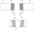
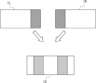
この点について、図8~図10を用いて説明する。図8は、仕切り板141、及び仕切り板142の厚さが同じである比較例の構成を示している。図9は、図8の構成において、ユーザが視認する像を模式的に示す図である。図10は、図7の構成において、ユーザが視認する像を模式的に示す図である。図9、図10では、左眼で視認される像を左眼像IL,右眼で視認される像を右眼像IRとし、両眼で視認される像を両眼像ICとしている。
This point will be explained using FIGS. 8 to 10. FIG. 8 shows the configuration of a comparative example in which the partition plates 141 and 142 have the same thickness. FIG. 9 is a diagram schematically showing an image visually recognized by a user in the configuration of FIG. 8. FIG. 10 is a diagram schematically showing an image visually recognized by a user in the configuration of FIG. 7. In FIGS. 9 and 10, the image visually recognized by the left eye is the left eye image IL, the image visually recognized by the right eye is the right eye image IR, and the image visually recognized by both eyes is the binocular image IC.
図8では、仕切り板141、及び仕切り板142の厚さが一定である。よって、仕切り板142は、仕切り板141の端部141aの厚さよりも厚く形成されていない。仕切り板141と仕切り板142は、少なくともビームスプリッタ122の厚さ分だけ離れて配置されている。
In FIG. 8, the thicknesses of the partition plates 141 and 142 are constant. Therefore, the partition plate 142 is not formed thicker than the thickness of the end portion 141a of the partition plate 141. The partition plate 141 and the partition plate 142 are spaced apart by at least the thickness of the beam splitter 122.
仕切り板142の厚さが、仕切り板141の端部141aの厚さと同じ場合、仕切り板141の端部141aが左眼EL及び右眼ERによって視認されてしまう。また、端部141aのみではなく、左眼ELから右斜め前に向かう光線の延びた先にあるコンバイナ121Rや、外光、フレーム102の内側等が視認されてしまう可能性もある。また、右眼ERから左斜め前に向かう光線の延びた先にあるコンバイナ121Lや、外光、フレーム102の内側等が視認されてしまう可能性もある。仕切り板141の端部141a、コンバイナ121L、121Rや、外光、及びフレーム102の内側等に表示光PL11等が入射すると、光が左眼EL又は右眼ERの方向に反射してしまい、ビームスプリッタ122を透過して左眼EL又は右眼ERに入射してしまう。よって、図9に示すように、ユーザが視認する左眼像IL、右眼像IR、及び両眼像ICに明るい斜め線170が入ってしまう。端部141a等での反射により、視認される像に、斜め線170が形成されてしまう。仕切り板141と仕切り板142の境界部分が明るく光ってしまうため、ユーザが斜め線170を視認してしまう。
If the thickness of the partition plate 142 is the same as the thickness of the end portion 141a of the partition plate 141, the end portion 141a of the partition plate 141 will be visually recognized by the left eye EL and the right eye ER. Furthermore, there is a possibility that not only the end portion 141a but also the combiner 121R, external light, the inside of the frame 102, etc., which is the end of the light beam extending diagonally forward to the right from the left eye EL, will be visible. Furthermore, there is a possibility that the combiner 121L, external light, the inside of the frame 102, etc., which are located at the end of the light beam extending diagonally forward to the left from the right eye ER, will be visible. When display light PL11, etc. enters the end portion 141a of the partition plate 141, the combiners 121L and 121R, external light, and the inside of the frame 102, the light is reflected in the direction of the left eye EL or right eye ER, and the beam The light passes through the splitter 122 and enters the left eye EL or right eye ER. Therefore, as shown in FIG. 9, a bright diagonal line 170 appears in the left eye image IL, right eye image IR, and binocular image IC that are visually recognized by the user. Due to the reflection at the end portion 141a and the like, a diagonal line 170 is formed in the visually recognized image. Since the boundary between the partition plate 141 and the partition plate 142 shines brightly, the user visually recognizes the diagonal line 170.
これに対して、本実施の形態では、図7に示すように端部142aが、端部141aよりも厚くなっている。端部141a、コンバイナ121L、121Rや、外光、及びフレーム102の内側等で反射して左眼EL又は右眼ERの方向に向かう光が端部142aで遮光される。よって、図10に示すように、ユーザが斜め線のない左眼像IL、右眼像IR、及び両眼像ICを視認することができる。つまり、端部141a等で反射した光が左眼EL又は右眼ERに到達するのを防ぐことができる。換言すると、端部142aの厚さは、端部141aが視認されないような厚さとすることが好ましい。また端部142aの厚さは、端部141aのみではなく、左眼ELから右斜め前に向かう光線の延びた先にあるコンバイナ121Rや、外光、フレーム102の内側等が視認されないような厚さとすることが好ましい。また端部142aの厚さは、右眼ERから左斜め前に向かう光線の延びた先にあるコンバイナ121Lや、外光、フレーム102の内側等が視認されないような厚さとすることが好ましい。これにより、端部141aでの反射光で形成される斜め線170が視認されるのを防ぐことができるため、より高い表示品質を実現することが可能となる。
On the other hand, in this embodiment, as shown in FIG. 7, the end portion 142a is thicker than the end portion 141a. The end 142a blocks light that is reflected from the end 141a, the combiners 121L and 121R, external light, and the inside of the frame 102 and heads toward the left eye EL or right eye ER. Therefore, as shown in FIG. 10, the user can visually recognize the left eye image IL, right eye image IR, and binocular image IC without diagonal lines. That is, it is possible to prevent the light reflected from the end portion 141a etc. from reaching the left eye EL or the right eye ER. In other words, the thickness of the end portion 142a is preferably such that the end portion 141a is not visible. The thickness of the end portion 142a is set so that not only the end portion 141a but also the combiner 121R, outside light, the inside of the frame 102, etc., which is the end of the light beam extending diagonally forward from the left eye EL to the right, are not visible. It is preferable to do so. Further, the thickness of the end portion 142a is preferably such that the combiner 121L, external light, the inside of the frame 102, etc., which are located at the end of the light beam extending diagonally forward to the left from the right eye ER, are not visible. This can prevent the diagonal line 170 formed by the reflected light from the end portion 141a from being visible, making it possible to achieve higher display quality.
例えば、仕切り板141の端部141aの厚さを1mmとし、仕切り板142の端部142aの厚さを2mmとすることができる。もちろん、端部141a、端部142aの厚さが特に限定されるものではない。例えば、端部142aの厚さは、端部141aの厚さの2倍以上となっていても良い。仕切り板141、及び仕切り板142は左右対称な形状として、左右方向(X方向)の中心に配置することが好ましい。
For example, the thickness of the end portion 141a of the partition plate 141 may be 1 mm, and the thickness of the end portion 142a of the partition plate 142 may be 2 mm. Of course, the thicknesses of the end portions 141a and 142a are not particularly limited. For example, the thickness of the end portion 142a may be twice or more the thickness of the end portion 141a. It is preferable that the partition plate 141 and the partition plate 142 have a symmetrical shape and be arranged at the center in the left-right direction (X direction).
さらに、仕切り板142がテーパ状に形成されていて側面の角度が一定であるため、表示光PL12及び外光PL21などによって仕切り板142に影が生じるのを防ぐことができる。よって、仕切り板142において、局所的に暗く視認される部分が生じることを防ぐことができ、より高い表示品質を得ることができる。
Furthermore, since the partition plate 142 is formed in a tapered shape and the angle of the side surface is constant, it is possible to prevent shadows from being cast on the partition plate 142 due to display light PL12, external light PL21, and the like. Therefore, it is possible to prevent a portion of the partition plate 142 from appearing locally dark, and it is possible to obtain higher display quality.
なお、仕切り板142は、のビームスプリッタ122側の端部142aが仕切り板141の端部141aよりも厚く形成されているが、端部142aの近傍が仕切り板141の端部141aよりも厚く形成されていてもよい。端部142aの近傍とは、仕切り板142において端部142aから-Z方向の位置の厚さを仕切り板141の端部141aよりも厚く形成した場合に、端部141a等が視認されない位置のことである。つまり、仕切り板142のビームスプリッタ122側の端部142a又は端部142aの近傍の厚さが、仕切り板141のビームスプリッタ122側の端部141aの厚さよりも厚くなっていればよい。
Note that the end portion 142a of the partition plate 142 on the side of the beam splitter 122 is formed thicker than the end portion 141a of the partition plate 141; may have been done. The vicinity of the end 142a refers to a position where the end 141a etc. are not visible when the thickness of the partition plate 142 in the −Z direction from the end 142a is made thicker than the end 141a of the partition plate 141. It is. That is, it is sufficient that the thickness of the end 142a of the partition plate 142 on the beam splitter 122 side or the vicinity of the end 142a is thicker than the thickness of the end 141a of the partition plate 141 on the beam splitter 122 side.
仕切り板142の端部142aの近傍が仕切り板141の端部141aよりも厚く形成されている場合、仕切り板142は-Z側の端部から+Z方向に向かうにつれて端部142aの近傍まで厚くなっていけばよく、端部142aの近傍から端部142aまでの形状は問わない。仕切り板142の形状は、端部142aの近傍から端部142aまで一様な厚さでもよいし、端部142aの近傍から端部142aに向かうにつれて薄くなっていってもよい。
When the vicinity of the end 142a of the partition plate 142 is formed thicker than the end 141a of the partition plate 141, the partition plate 142 becomes thicker from the end on the -Z side toward the +Z direction to the vicinity of the end 142a. The shape from the vicinity of the end portion 142a to the end portion 142a does not matter. The shape of the partition plate 142 may have a uniform thickness from the vicinity of the end 142a to the end 142a, or may become thinner from the vicinity of the end 142a toward the end 142a.
変形例
図7では、仕切り板142の厚さがテーパ状に変化していたが、仕切り板142はテーパ形状に限られるものでない。以下、変形例にかかる仕切り板142の形状について説明する。
Modified Example In FIG. 7, the thickness of the partition plate 142 changes into a tapered shape, but the partition plate 142 is not limited to a tapered shape. The shape of the partition plate 142 according to the modified example will be explained below.
図11は、仕切り板142の変形例1の形状を示す図である。図11では、仕切り板142の厚さが段階的に変化している。よって、仕切り板142のXZ断面がT字状となっている。具体的には、仕切り板142のビームスプリッタ122側の端部142aのみが厚くなっている。よって、仕切り板142は、ビームスプリッタ122側の端部142aに肉厚部142bを有している。
FIG. 11 is a diagram showing the shape of Modification 1 of the partition plate 142. In FIG. 11, the thickness of the partition plate 142 changes stepwise. Therefore, the XZ cross section of the partition plate 142 is T-shaped. Specifically, only the end portion 142a of the partition plate 142 on the beam splitter 122 side is thick. Therefore, the partition plate 142 has a thick portion 142b at the end 142a on the beam splitter 122 side.
図12は、仕切り板142の変形例2の形状を示す図である。図12では、仕切り板142の厚さが段階的に変化している。具体的には、仕切り板142のビームスプリッタ122側の端部142aから離れた箇所が厚くなっている。図12のように、仕切り板142のXZ断面が十字状となっている。よって、仕切り板142は、ビームスプリッタ122側の端部142aの近傍に肉厚部142bを有している。つまり仕切り板142は、端部142aから-Z方向の位置に、端部141a等が視認されないように肉厚部142bを配置すればよい。
FIG. 12 is a diagram showing the shape of a second modification of the partition plate 142. In FIG. 12, the thickness of the partition plate 142 changes in stages. Specifically, the portion of the partition plate 142 that is away from the end portion 142a on the beam splitter 122 side is thicker. As shown in FIG. 12, the XZ cross section of the partition plate 142 has a cross shape. Therefore, the partition plate 142 has a thick portion 142b near the end portion 142a on the beam splitter 122 side. In other words, the thick portion 142b of the partition plate 142 may be arranged at a position in the -Z direction from the end 142a so that the end 141a and the like are not visible.
図13は、仕切り板142の変形例3の形状を示す図である。図13では、仕切り板142の厚さが一定となっている。よって、仕切り板142のZ方向の位置に関わらず全体が端部141aの厚さよりも厚くなっている。変形例1~3の構成であっても、端部141a等で反射した反射光が仕切り板142で遮光される。よって、左眼EL又は右眼ERから端部141a等が視認されるのを防ぐことができる。
FIG. 13 is a diagram showing the shape of the third modification of the partition plate 142. In FIG. 13, the thickness of the partition plate 142 is constant. Therefore, regardless of the position of the partition plate 142 in the Z direction, the entire thickness is greater than the thickness of the end portion 141a. Even in the configurations of Modifications 1 to 3, the partition plate 142 blocks the reflected light reflected from the end portion 141a and the like. Therefore, it is possible to prevent the end portion 141a and the like from being visually recognized from the left eye EL or right eye ER.
仕切り板142の形状は、図示する形状に限られるものではない。仕切り板142が、仕切り板141の端部141aの厚さよりも厚ければよい。図7、図11、図12のように仕切り板142の一部が端部141aの厚さよりも厚くてもよく、図13のように仕切り板142の全部が端部141aの厚さよりも厚くてもよい。つまり、仕切り板142の一部又は全部が端部141aの厚さよりも厚ければよい。少なくとも仕切り板142のビームスプリッタ122側の端部142a、又は端部142aの近傍が、端部141aよりも厚くなっていることが好ましい。これにより、仕切り板141の端部141a等での反射光による斜め線170が視認されるのを防ぐことができる。よって、高い表示品質を得ることができる。
The shape of the partition plate 142 is not limited to the illustrated shape. It is sufficient that the partition plate 142 is thicker than the end portion 141a of the partition plate 141. As shown in FIGS. 7, 11, and 12, part of the partition plate 142 may be thicker than the end portion 141a, and as shown in FIG. 13, the entire partition plate 142 may be thicker than the end portion 141a. Good too. In other words, it is sufficient that part or all of the partition plate 142 is thicker than the end portion 141a. It is preferable that at least the end 142a of the partition plate 142 on the beam splitter 122 side or the vicinity of the end 142a is thicker than the end 141a. Thereby, it is possible to prevent the diagonal line 170 caused by the reflected light from the end portion 141a of the partition plate 141 from being visible. Therefore, high display quality can be obtained.
また、図7、図11、図12、図13では、仕切り板141が一定の厚さの平行平板となっているが、仕切り板141の形状は特に限定される物ではない。例えば、図7の仕切り板142と同様に、仕切り板141がテーパ形状となっていてもよい。つまり、端部141aから+Z方向に向かうにつれて、仕切り板141の厚さが厚くなっていてもよい。
Further, in FIGS. 7, 11, 12, and 13, the partition plate 141 is a parallel flat plate with a constant thickness, but the shape of the partition plate 141 is not particularly limited. For example, like the partition plate 142 in FIG. 7, the partition plate 141 may have a tapered shape. That is, the thickness of the partition plate 141 may become thicker as it goes in the +Z direction from the end portion 141a.
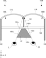
さらに、本実施の形態では仕切り板141と仕切り板142の拡散反射率を異なる値としてもよい。この点について、図14を用いて説明する。図14は、仕切り板141,142で拡散反射する外光の光量を説明するための図である。なお、左眼用光学系103Lと右眼用光学系103Rでは同じ構成となっているため、左眼用光学系103Lのみを説明する。
Furthermore, in this embodiment, the diffuse reflectance of partition plate 141 and partition plate 142 may be set to different values. This point will be explained using FIG. 14. FIG. 14 is a diagram for explaining the amount of external light that is diffusely reflected by the partition plates 141 and 142. Note that since the left eye optical system 103L and the right eye optical system 103R have the same configuration, only the left eye optical system 103L will be described.
図14では、仕切り板141、142で拡散反射した外光のうち、10%程度が左眼ELに向かうものとして説明する。つまり、仕切り板141の箇所C、及び仕切り板142の箇所Dのいずれにおいても、仕切り板141,142に入射した外光の1/10程度が、左眼ELの方向に反射されるものと仮定する。また、コンバイナ121L及びビームスプリッタ122の透過率が50%、反射率が50%であると仮定する。
In FIG. 14, description will be made assuming that about 10% of the external light diffusely reflected by the partition plates 141 and 142 is directed toward the left eye EL. In other words, it is assumed that approximately 1/10 of the external light incident on the partition plates 141 and 142 is reflected in the direction of the left eye EL at both the location C of the partition plate 141 and the location D of the partition plate 142. do. Further, it is assumed that the transmittance of the combiner 121L and the beam splitter 122 is 50% and the reflectance is 50%.
まず、ビームスプリッタ122に入射する前に仕切り板141で拡散反射する外光PL211について説明する。コンバイナ121Lを透過した外光PL211は、箇所Cにおいて、仕切り板141に入射する。ここで、コンバイナ121Lに入射する前の外光PL211の光量を100とすると、コンバイナ121Lを透過した外光PL211の光量は50(=100×0.5)となる。
First, the external light PL211 that is diffusely reflected by the partition plate 141 before entering the beam splitter 122 will be described. The external light PL211 that has passed through the combiner 121L is incident on the partition plate 141 at a location C. Here, assuming that the amount of external light PL211 before entering the combiner 121L is 100, the amount of external light PL211 that has passed through the combiner 121L is 50 (=100×0.5).
そして、箇所Cで拡散した外光PL211の一部は、ビームスプリッタ122を透過して、左眼ELに入射する。箇所Cで拡散して左眼ELに向かう外光PL211の光量は5(=50×0.1)となる。さらに、ビームスプリッタ122を透過して左眼ELに到達する外光PL211の光量は、2.5(=5×0.5)となる。
Then, a part of the external light PL211 diffused at the point C passes through the beam splitter 122 and enters the left eye EL. The amount of external light PL211 diffused at point C and directed toward left eye EL is 5 (=50×0.1). Furthermore, the amount of external light PL211 that passes through the beam splitter 122 and reaches the left eye EL is 2.5 (=5×0.5).
次に、ビームスプリッタ122に入射した後に拡散反射する外光PL212について説明する。外光PL212は、コンバイナ121Lを透過した後、ビームスプリッタ122に入射する。従って、コンバイナ121Lを透過した外光PL212の半分がビームスプリッタ122を透過して、残りの半分がビームスプリッタ122で反射される。外光PL212のうち、ビームスプリッタ122で反射した光を外光PL213とする。外光PL212のうち、ビームスプリッタ122を透過した光を外光PL214とする。
Next, the external light PL212 that is diffusely reflected after entering the beam splitter 122 will be described. The external light PL212 enters the beam splitter 122 after passing through the combiner 121L. Therefore, half of the external light PL212 that has passed through the combiner 121L passes through the beam splitter 122, and the remaining half is reflected by the beam splitter 122. Of the external light PL212, the light reflected by the beam splitter 122 is defined as external light PL213. Of the external light PL212, the light that has passed through the beam splitter 122 is defined as external light PL214.
コンバイナ121Lに入射する前の外光PL212の光量を100とすると、コンバイナ121Lを透過した直後の外光PL212の光量は50(=100×0.5)となる。さらに、ビームスプリッタ122で反射した直後の外光PL213の光量は25(=50×0.5)となる。ビームスプリッタ122を透過した直後の外光PL214の光量は25(=50×0.5)となる。
If the amount of external light PL212 before entering the combiner 121L is 100, then the amount of external light PL212 immediately after passing through the combiner 121L is 50 (=100×0.5). Further, the amount of external light PL213 immediately after being reflected by the beam splitter 122 is 25 (=50×0.5). The amount of external light PL214 immediately after passing through the beam splitter 122 is 25 (=50×0.5).
そして、外光PL213は、箇所Cにおいて仕切り板141で拡散反射される。仕切り板141で拡散反射した外光PL213の一部は、左眼ELに向かう。仕切り板141で拡散反射されて左眼ELに向かう外光PL213の光量は2.5(=25×0.1)となる。さらに、外光PL213は、ビームスプリッタ122を透過した後に、左眼ELに入射する。よって、左眼ELに到達する外光PL213の光量は1.25(=2.5×0.5)となる。
Then, the external light PL213 is diffusely reflected by the partition plate 141 at the location C. A portion of the external light PL213 diffusely reflected by the partition plate 141 heads toward the left eye EL. The amount of external light PL213 that is diffusely reflected by the partition plate 141 and directed toward the left eye EL is 2.5 (=25×0.1). Furthermore, the external light PL213 enters the left eye EL after passing through the beam splitter 122. Therefore, the amount of external light PL213 reaching the left eye EL is 1.25 (=2.5×0.5).
外光PL214は、箇所Dにおいて、仕切り板142で拡散反射される。仕切り板142で拡散反射した外光PL214の一部は、左眼ELに向かう。仕切り板142で拡散反射されて左眼ELに向かう外光PL214の光量は2.5(=25×0.1)となる。よって、左眼ELに到達する外光PL214の光量は2.5となる。
At location D, the external light PL214 is diffusely reflected by the partition plate 142. A portion of the external light PL214 diffusely reflected by the partition plate 142 heads toward the left eye EL. The amount of external light PL214 that is diffusely reflected by the partition plate 142 and directed toward the left eye EL is 2.5 (=25×0.1). Therefore, the amount of external light PL214 reaching the left eye EL is 2.5.
したがって、箇所Cで拡散反射した外光PL211、外光PL213の合計光量は、3.75(=2.5+1.25)となる。一方、箇所Dで拡散反射した外光PL214の光量は、2.5となる。箇所Cと箇所Dとでユーザに視認される明るさに違いが生じてしまう。ユーザにとって、箇所Cのほうが、箇所Dよりも明るく視認されることになる。換言すると、ユーザには、仕切り板141のほうが仕切り板142よりも明るく視認される。
Therefore, the total amount of external light PL211 and external light PL213 diffusely reflected at point C is 3.75 (=2.5+1.25). On the other hand, the amount of external light PL214 diffusely reflected at location D is 2.5. There will be a difference in brightness visually recognized by the user between location C and location D. For the user, location C appears brighter than location D. In other words, the partition plate 141 is visually recognized as brighter than the partition plate 142 by the user.
そこで、本実施の形態では、仕切り板141と仕切り板142との拡散反射率を異なる値としている。具体的には、仕切り板142の拡散反射率を仕切り板141の拡散反射率よりも高くしている。これにより、仕切り板141と仕切り板142との間の明るさの違いを低減することができるため、より高い表示品質を得ることができる。つまり、仕切り板141と仕切り板142の拡散反射率を調整することで仕切り部140の明るさの不均一性を補正することができる。よって、より高い表示品質を得ることが可能になる。
Therefore, in this embodiment, the diffuse reflectance of the partition plate 141 and the partition plate 142 are set to different values. Specifically, the diffuse reflectance of the partition plate 142 is made higher than the diffuse reflectance of the partition plate 141. Thereby, the difference in brightness between the partition plate 141 and the partition plate 142 can be reduced, so that higher display quality can be obtained. That is, by adjusting the diffuse reflectance of the partition plate 141 and the partition plate 142, it is possible to correct the non-uniformity of the brightness of the partition section 140. Therefore, it becomes possible to obtain higher display quality.
なお、仕切り板141を仕切り板142よりもより濃い色で着色すればよい。このようにすると仕切り板142の光の拡散反射率が、仕切り板141の光の拡散反射率よりも高くなる。仕切り板142の拡散反射率を仕切り板141の拡散反射率の1.5倍程度とすることで、ユーザが仕切り板141を仕切り板142とを同程度の明るさで視認することができる。もちろん、仕切り板142の拡散反射率は仕切り板141の拡散反射率の1.5倍以上であってもよく、1.5倍以下であってもよい。
Note that the partition plate 141 may be colored darker than the partition plate 142. In this way, the diffuse reflectance of light on the partition plate 142 becomes higher than the diffuse reflectance of light on the partition plate 141. By setting the diffuse reflectance of the partition plate 142 to about 1.5 times that of the partition plate 141, the user can visually recognize the partition plate 141 and the partition plate 142 with approximately the same brightness. Of course, the diffuse reflectance of the partition plate 142 may be 1.5 times or more than the diffuse reflectance of the partition plate 141, or may be 1.5 times or less.
仕切り板141と仕切り板142とは同系色で色の濃淡のみを変えることによって、拡散反射率を異ならせるようにすればよい。仕切り板141と仕切り板142をグレーとした場合は、白と黒との混合比を変えることで色の濃淡を変え、拡散反射率を異ならせればよい。拡散反射率の低い濃いグレーとしたい場合は黒の比率を増やした色とし、拡散反射率の高い淡いグレーとしたい場合は白の比率を増やした色とすればよい。
The partition plate 141 and the partition plate 142 may have similar colors and may have different diffuse reflectances by changing only the shade of the color. When the partition plate 141 and the partition plate 142 are made of gray, the light and shade of the color may be changed by changing the mixing ratio of white and black, and the diffuse reflectance may be varied. If you want a dark gray with a low diffuse reflectance, use a color with an increased proportion of black, and if you want a light gray with a high diffuse reflectance, use a color with an increased proportion of white.
ビームスプリッタ122よりも前方(+Z方向)と後方(-Z方向)とで、仕切り板141と仕切り板142との表面の拡散反射加工を変えることによって、拡散反射率を異ならせてもよい。仕切り板141と仕切り板142との一方を拡散反射率の高い拡散反射加工として、他方を拡散反射率の低い拡散反射加工とすればよい。拡散反射率を高くしたい場合は凸凹のピッチを狭くすればよく、拡散反射率を低くしたい場合は凸凹のピッチを広くすればよい。
The diffuse reflectance may be made different by changing the diffuse reflection processing of the surfaces of the partition plates 141 and 142 in front (+Z direction) and behind (−Z direction) of the beam splitter 122. One of the partition plates 141 and 142 may be subjected to a diffuse reflection process with a high diffuse reflectance, and the other may be subjected to a diffuse reflection process with a low diffuse reflectance. If you want to increase the diffuse reflectance, you can narrow the pitch between the concave and convex portions, and if you want to decrease the diffuse reflectance, you can widen the pitch between the concave and convex portions.
仕切り板141と仕切り板142を肌色とした場合は、人間が視覚で感じる反射率を数値化したものである視感反射率を変えることで肌色の濃淡を変え、拡散反射率を異ならせればよい。視感反射率はCIE色度図で表されない明るさ(明度)を表すため、仕切り板141と仕切り板142の色のCIE色度座標は変えずに、視感反射率のみを変えればよい。拡散反射率の低い濃い肌色としたい場合は視感反射率の低い肌色とし、拡散反射率の高い淡い肌色としたい場合は視感反射率の高い肌色とすればよい。
If the partition plate 141 and the partition plate 142 are skin-colored, the shading of the skin color can be changed by changing the luminous reflectance, which is a numerical representation of the reflectance that humans perceive visually, and the diffuse reflectance can be made different. . Since the luminous reflectance represents brightness (brightness) that is not expressed in the CIE chromaticity diagram, it is sufficient to change only the luminous reflectance without changing the CIE chromaticity coordinates of the colors of the partition plates 141 and 142. If you want a dark skin color with low diffuse reflectance, you can use a skin color with low luminous reflectance, and if you want a pale skin color with high diffuse reflectance, you can use a skin color with high luminous reflectance.
仕切り板141、142の色の濃淡、又は視感反射率を変えること、及び仕切り板141、142の表面の凸凹のピッチを変えることで、ビームスプリッタ122よりも前方(+Z方向)と後方(-Z方向)とで、仕切り部140の拡散反射率を異ならせることができる。これにより、仕切り板141と仕切り板142を自然に視認することができるため、表示品質を向上することができる。
By changing the color shading or luminous reflectance of the partition plates 141 and 142, and by changing the pitch of the unevenness on the surface of the partition plates 141 and 142, the beam splitter 122 can be moved forward (+Z direction) and behind (- Z direction), the diffuse reflectance of the partition portion 140 can be made different. Thereby, the partition plate 141 and the partition plate 142 can be visually recognized naturally, so that display quality can be improved.
さらには、仕切り板141において拡散反射率の空間分布を設けてもよい。例えば、図15のように、前方(+Z方向)ほど、仕切り板141の拡散反射率を低くしてもよい。図15は、色の濃い部分ほど拡散反射率が低いことを示し、色の薄い部分ほど拡散反射率が高いことを示している。あるいは、前方(+Z方向)ほど、仕切り板141の拡散反射率を高くしてもよい。また、上下方向(Y方向)に、仕切り板141において拡散反射率の空間分布を設けてもよい。同様に、仕切り板142において拡散反射率の空間分布を設けてもよい。つまり、仕切り部140が強調して表示されることがないように、仕切り板141、142の拡散反射率に空間分布を設ければよい。
Furthermore, a spatial distribution of diffuse reflectance may be provided in the partition plate 141. For example, as shown in FIG. 15, the diffuse reflectance of the partition plate 141 may be lowered toward the front (+Z direction). FIG. 15 shows that the darker the color, the lower the diffuse reflectance, and the lighter the color, the higher the diffuse reflectance. Alternatively, the diffuse reflectance of the partition plate 141 may be made higher toward the front (+Z direction). Further, a spatial distribution of diffuse reflectance may be provided in the partition plate 141 in the vertical direction (Y direction). Similarly, a spatial distribution of diffuse reflectance may be provided in the partition plate 142. In other words, a spatial distribution may be provided for the diffuse reflectance of the partition plates 141 and 142 so that the partition part 140 is not displayed in an emphasized manner.
変形例4.
図16は、仕切り板142の変形例4の形状を示す図である。図16では、仕切り板142の厚さがテーパ状に変化している。具体的には、図7と同様に、-Z側の端部から+Z方向に向かうにつれて、仕切り板142の厚さが厚くなっていく。さらに、図7に比べて、仕切り板142のビームスプリッタ122側の端部142aの厚さが厚くなっている。具体的には、仕切り板142の端部142aが、ユーザから第1の仕切り板を視認できなくなるような厚さで形成されている。仕切り板142は、仕切り板141の端部141aを隠すだけでなく、仕切り板141の全体を隠すことができる。
Modification example 4.
FIG. 16 is a diagram showing the shape of a fourth modification of the partition plate 142. In FIG. 16, the thickness of the partition plate 142 is tapered. Specifically, as in FIG. 7, the thickness of the partition plate 142 increases from the −Z side end toward the +Z direction. Furthermore, compared to FIG. 7, the end portion 142a of the partition plate 142 on the beam splitter 122 side is thicker. Specifically, the end portion 142a of the partition plate 142 is formed to have such a thickness that the first partition plate cannot be visually recognized by the user. The partition plate 142 can not only hide the end portion 141a of the partition plate 141, but also hide the entire partition plate 141.
このようにすることで、仕切り板141の全体が視認されるのを防ぐことができる。つまり、仕切り板141の前方側(+Z側)の端部が、仕切り板142で隠れるため、ユーザが仕切り板141を視認することができなくなる。仕切り板141で反射して左眼EL又は右眼ERに向かう光が仕切り板142で遮光される。上記のように、仕切り板141と仕切り板142とは異なる光学条件でユーザに視認されてしまう。本変形例では、ユーザに対して仕切り板141を隠すように、仕切り板142の端部142aが厚くなっている。これにより、表示品質を向上することができる。よって、明るさの違いによる違和感を軽減することができるため、没入感を向上することができる。
By doing so, the entire partition plate 141 can be prevented from being visually recognized. In other words, the front end (+Z side) of the partition plate 141 is hidden by the partition plate 142, making it impossible for the user to visually recognize the partition plate 141. The light reflected by the partition plate 141 and directed toward the left eye EL or the right eye ER is blocked by the partition plate 142. As described above, the partition plate 141 and the partition plate 142 are visually recognized by the user under different optical conditions. In this modification, the end portion 142a of the partition plate 142 is thickened so as to hide the partition plate 141 from the user. Thereby, display quality can be improved. Therefore, the sense of discomfort caused by differences in brightness can be reduced, and the sense of immersion can be improved.
なお、図16では、仕切り板142の端部142aが、仕切り板141を全体に隠す厚さとなっているが、一部のみを隠す厚さとなっていてもよい。つまり、仕切り板142の端部142aが、ユーザから前記第1の仕切り板の少なくとも一部を視認できなくなるような厚さで形成されていればよい。換言すると、仕切り板141の前方側(+Z側)の端部をユーザが視認できるような厚さで、仕切り板142を形成してもよい。この場合であっても、仕切り板141と仕切り板142の明るさの違いによる違和感を低減することが可能となる。
In addition, in FIG. 16, the end portion 142a of the partition plate 142 has a thickness that completely hides the partition plate 141, but it may have a thickness that only partially hides the partition plate 141. That is, the end portion 142a of the partition plate 142 may be formed to have such a thickness that at least a portion of the first partition plate cannot be visually recognized by the user. In other words, the partition plate 142 may be formed with a thickness such that the front side (+Z side) end of the partition plate 141 can be visually recognized by the user. Even in this case, it is possible to reduce the discomfort caused by the difference in brightness between the partition plate 141 and the partition plate 142.
このように、ユーザから見ると、仕切り板141が仕切り板142で隠れる。すなわち、仕切り板141が仕切り板142でマスクされるため、ユーザから仕切り板141が視認されなくなる。これにより、表示品質を向上することができる。
In this way, when viewed from the user, the partition plate 141 is hidden by the partition plate 142. That is, since the partition plate 141 is masked by the partition plate 142, the partition plate 141 is no longer visible to the user. Thereby, display quality can be improved.
なお、図16では、仕切り板142がテーパ形状、つまり、逆三角形状に形成されているが、図11~図13に示した変形例1~3の構成を採用してもよい。例えば、図11で示したような肉厚部142bを端部142aに設けてもよい。この場合、不透明な肉厚部142bが、左眼EL又は右眼ERから仕切り板141までの間に介在する。これにより、ユーザから仕切り板141を隠すことができる。変形例4では、例えば、左眼ELと仕切り板141の任意の点を結ぶ直線上に不透明な仕切り板142が介在していればよい。同様に、右眼ERと仕切り板141の任意の点を結ぶ直線上に不透明な仕切り板142が介在していればよい。
In FIG. 16, the partition plate 142 is formed into a tapered shape, that is, an inverted triangular shape, but the configurations of Modifications 1 to 3 shown in FIGS. 11 to 13 may be adopted. For example, a thick portion 142b as shown in FIG. 11 may be provided at the end portion 142a. In this case, the opaque thick portion 142b is interposed between the left eye EL or the right eye ER and the partition plate 141. Thereby, the partition plate 141 can be hidden from the user. In the fourth modification, for example, the opaque partition plate 142 may be interposed on a straight line connecting the left eye EL and any point on the partition plate 141. Similarly, the opaque partition plate 142 may be interposed on a straight line connecting the right eye ER and any point on the partition plate 141.
変形例5.
図17は、仕切り板142の変形例5の形状を示す図である。図17では、図7又は図16と反対のテーパ形状となっている。具体的には、+Z側の端部から-Z方向に向かうにつれて、仕切り板142の厚さが徐々に厚くなっていく。なお、仕切り板142の-Z側(後方側)の面を底面142cとし、+X側(右側)及び-X側(左側)の面を側面142dとする。底面142cはユーザの顔に対向する面である。側面142dは左前方空間160L又は右前方空間160Rに対向する面である。
Modification example 5.
FIG. 17 is a diagram showing the shape of a fifth modification of the partition plate 142. In FIG. 17, the tapered shape is opposite to that in FIG. 7 or 16. Specifically, the thickness of the partition plate 142 gradually increases from the +Z side end toward the −Z direction. Note that the −Z side (rear side) surface of the partition plate 142 is a bottom surface 142c, and the +X side (right side) and −X side (left side) surfaces are a side surface 142d. The bottom surface 142c is a surface facing the user's face. The side surface 142d is a surface facing the left front space 160L or the right front space 160R.
仕切り板142は、前方に向かうにつれて徐々に薄くなっていくテーパ状になっている。よって、仕切り板142において、底面142cが最も厚くなり、端部142aが最も薄くなる。この構成とすれば、変形例4と同様に、仕切り板142によって、端部141aや、仕切り板141を隠すことができる。つまり、端部141a、及び仕切り板141が、底面142cで隠れて、ユーザから視認されなくなる。これにより、表示品質を向上することができる。さらに、仕切り板142の側面142dが底面142cに隠れて、ユーザから視認されなくなる。よって、側面142dに生じる影が視認されなくなり、表示品質を向上することができる。
The partition plate 142 has a tapered shape that gradually becomes thinner toward the front. Therefore, in the partition plate 142, the bottom surface 142c is the thickest, and the end portion 142a is the thinnest. With this configuration, the end portion 141a and the partition plate 141 can be hidden by the partition plate 142, similarly to the fourth modification. In other words, the end portion 141a and the partition plate 141 are hidden by the bottom surface 142c and are no longer visible to the user. Thereby, display quality can be improved. Furthermore, the side surface 142d of the partition plate 142 is hidden behind the bottom surface 142c and is no longer visible to the user. Therefore, the shadow appearing on the side surface 142d is no longer visible, and display quality can be improved.
なお、図17では、端部142aの厚さが端部141aの厚さよりも厚くなっているが、端部142aの厚さが端部141aの厚さ以下であってもよい。つまり、端部141aが底面142cで隠れていれば、仕切り板142の形状は特に限定されるものではない。仕切り板142は、コンバイナ121L、又は121Rで左眼EL又は右眼ERの方向に反射される表示光を遮らないような形状、サイズとすることが好ましい。具体的には、左眼ELからコンバイナ121Lまでの視線と右眼ERからコンバイナ121Rまでの視線を遮らないように仕切り板142を配置する。
Note that in FIG. 17, the thickness of the end portion 142a is thicker than the thickness of the end portion 141a, but the thickness of the end portion 142a may be less than or equal to the thickness of the end portion 141a. In other words, the shape of the partition plate 142 is not particularly limited as long as the end portion 141a is hidden by the bottom surface 142c. The partition plate 142 is preferably shaped and sized so as not to block the display light reflected in the direction of the left eye EL or right eye ER by the combiner 121L or 121R. Specifically, the partition plate 142 is arranged so as not to block the line of sight from the left eye EL to the combiner 121L and the line of sight from the right eye ER to the combiner 121R.
また、仕切り板142がビームスプリッタ122の固定をサポートするようにしてもよい。例えば、端部142aがビームスプリッタ122と当接することで、ビームスプリッタ122の位置を規制することができる。
Further, the partition plate 142 may support fixing of the beam splitter 122. For example, by bringing the end portion 142a into contact with the beam splitter 122, the position of the beam splitter 122 can be regulated.
実施の形態2.
実施の形態2では、仕切り板142以外の部材を用いて、ユーザから仕切り板141を隠している。図18は,実施の形態2の構成を示す上面図である。図19は、実施の形態2の構成を後方から見た模式図である。図20は、実施の形態2の構成を右眼側から見た模式図である。具体的には、図18~図20に示すように、マスク部材143が設けられている。なお、マスク部材143以外の構成は、実施の形態1と同様であるため、説明を省略する。また、図19、図20において、コンバイナ121L、121R等の構成要素は適宜省略されている。
Embodiment 2.
In the second embodiment, a member other than the partition plate 142 is used to hide the partition plate 141 from the user. FIG. 18 is a top view showing the configuration of the second embodiment. FIG. 19 is a schematic diagram of the configuration of the second embodiment viewed from the rear. FIG. 20 is a schematic diagram of the configuration of Embodiment 2 viewed from the right eye side. Specifically, as shown in FIGS. 18 to 20, a mask member 143 is provided. Note that the configuration other than the mask member 143 is the same as that in Embodiment 1, so the description will be omitted. Further, in FIGS. 19 and 20, components such as combiners 121L and 121R are omitted as appropriate.
マスク部材143は、例えば、ビームスプリッタ122に取り付けられている。ここでは、ビームスプリッタ122の後方側(-Z側)の面に取り付けられている。あるいは、仕切り板142又はフレーム102等にマスク部材143が取り付けられていてもよい。マスク部材143は、三角形状のシートとなっている。もちろん、マスク部材143は、仕切り板141を隠すことができる形状であれば、三角形状に限られるものではない。マスク部材143を粘着シートとして、ビームスプリッタ122に貼り付けてもよい。マスク部材143は、薄いシートのようなフレキシブルな部材であってもよく、ある程度の厚みを有する板状部材であってもよい。仕切り板141で反射して左眼EL又は右眼ERに向かう光がマスク部材143で遮光される。よって、変形例4と同様に、表示品質を向上することができる。
For example, the mask member 143 is attached to the beam splitter 122. Here, it is attached to the rear side (-Z side) surface of the beam splitter 122. Alternatively, the mask member 143 may be attached to the partition plate 142, the frame 102, or the like. The mask member 143 is a triangular sheet. Of course, the mask member 143 is not limited to a triangular shape as long as it can hide the partition plate 141. The mask member 143 may be attached to the beam splitter 122 using an adhesive sheet. The mask member 143 may be a flexible member such as a thin sheet, or may be a plate-like member having a certain degree of thickness. Light reflected by the partition plate 141 and directed toward the left eye EL or the right eye ER is blocked by the mask member 143. Therefore, similarly to the fourth modification, display quality can be improved.
マスク部材143は、仕切り板142と同等の光学特性を有することが好ましい。例えば、仕切り板142と同じ色、かつ、同じ拡散反射率を有する部材とすることが好ましい。このようにすることで、明るさの違いによる違和感を抑制することができ、没入感を向上することができる。
It is preferable that the mask member 143 has the same optical characteristics as the partition plate 142. For example, it is preferable to use a member having the same color and the same diffuse reflectance as the partition plate 142. By doing so, it is possible to suppress the sense of discomfort caused by differences in brightness, and it is possible to improve the sense of immersion.
マスク部材143は、仕切り板142の左右両側に対称に配置されている。また、マスク部材143は、仕切り板142よりも左側(-X側)の領域と右側(+X側)の領域とで別々の部材であってもよく、共通の部材であってもよい。
The mask members 143 are arranged symmetrically on both left and right sides of the partition plate 142. Furthermore, the mask member 143 may be separate members for the region on the left side (−X side) and the region on the right side (+X side) of the partition plate 142, or may be a common member.
なお、マスク部材143は、仕切り板141の全体を隠すようなサイズとなっているが、仕切り板141の端部141aを隠すサイズであってもよい。例えば、マスク部材143は、図11の肉厚部142b程度のサイズであってもよい。この場合であっても、仕切り板141の端部141aで反射して左眼EL又は右眼ERに向かう光がマスク部材143で遮光される。よって、実施の形態1と同様に、表示品質を向上することができる。
Although the mask member 143 is sized to hide the entire partition plate 141, it may be sized to hide the end portion 141a of the partition plate 141. For example, the mask member 143 may have a size approximately equal to the thick portion 142b in FIG. 11. Even in this case, the mask member 143 blocks light that is reflected by the end 141a of the partition plate 141 and goes toward the left eye EL or the right eye ER. Therefore, similar to Embodiment 1, display quality can be improved.
このように、本実施の形態1,2、及びその変形例では、ユーザから第1の仕切り板141のビームスプリッタ122側の端部141aを隠している。ユーザから端部141aを隠すとは、ユーザから端部141aが視認できなくなる状態を示す。例えば、ユーザの左眼EL又は右眼ERから端部141aまでの間に、不透明な部材(仕切り板142、又はマスク部材143)が介在することで、ユーザから端部141aを隠すことができる。このような不透明な部材は、仕切り板142自体でもよく、仕切り板142に取り付けられた部材でもよく、仕切り板142とは別個の部材でもよい。
In this manner, in the first and second embodiments and their modifications, the end 141a of the first partition plate 141 on the beam splitter 122 side is hidden from the user. Hiding the end portion 141a from the user refers to a state in which the end portion 141a is no longer visible to the user. For example, by interposing an opaque member (partition plate 142 or mask member 143) between the user's left eye EL or right eye ER and the end portion 141a, the end portion 141a can be hidden from the user. Such an opaque member may be the partition plate 142 itself, a member attached to the partition plate 142, or a member separate from the partition plate 142.
例えば、図7,図11~図13等に示すように、仕切り板142を厚くすることで、ユーザから仕切り板141の端部141aを隠すことができる。仕切り板141の端部141aが視認されないため、明るい斜め線170(図9参照)が視認されるのを防ぐことができる。よって,ユーザが違和感なく画像を視認することができる。
For example, as shown in FIGS. 7, 11 to 13, etc., by making the partition plate 142 thicker, the end portion 141a of the partition plate 141 can be hidden from the user. Since the end portion 141a of the partition plate 141 is not visible, it is possible to prevent the bright diagonal line 170 (see FIG. 9) from being visible. Therefore, the user can view the image without feeling uncomfortable.
また、実施の形態2のように、仕切り板141とは別のマスク部材143を設けることで、仕切り板141の端部141aをマスクするようにしてもよい。マスク部材143を左眼EL又は右眼ERから仕切り板141までの間に配置すればよい。
Further, as in the second embodiment, a mask member 143 separate from the partition plate 141 may be provided to mask the end portion 141a of the partition plate 141. The mask member 143 may be placed between the left eye EL or right eye ER and the partition plate 141.
仕切り板142又はマスク部材143のような不透明な部材を用いて、端部141aをマスクするようにしてもよい。仕切り板141の端部141aが視認されないため、明るい斜め線170(図9参照)が視認されるのを防ぐことができる。よって,ユーザが違和感なく画像を視認することができる。また、仕切り板142、又はマスク部材143は、図16等のように仕切り板141の全体を隠すようにしてもよく、図7、図11等のように端部141a側の一部のみを隠すようにしてもよい。
An opaque member such as the partition plate 142 or the mask member 143 may be used to mask the end portion 141a. Since the end portion 141a of the partition plate 141 is not visible, it is possible to prevent the bright diagonal line 170 (see FIG. 9) from being visible. Therefore, the user can view the image without feeling uncomfortable. Furthermore, the partition plate 142 or the mask member 143 may be configured to hide the entire partition plate 141 as shown in FIG. You can do it like this.
実施の形態3.
実施の形態3では、仕切り板142に、視線を検出するための光源及び光センサが設けられている。実施の形態3にかかるヘッドマウントディスプレイ100について、図21、図22を用いて説明する。図21,図22は、それぞれヘッドマウントディスプレイ100の構成を模式的に示す上面図及び側面図であり、適宜簡略がなされている。例えば、図22では、仕切り板141仕切り板142及びが省略されている。
Embodiment 3.
In the third embodiment, the partition plate 142 is provided with a light source and an optical sensor for detecting line of sight. The head mounted display 100 according to the third embodiment will be explained using FIGS. 21 and 22. 21 and 22 are a top view and a side view, respectively, schematically showing the configuration of the head mounted display 100, and are simplified as appropriate. For example, in FIG. 22, the partition plates 141 and 142 are omitted.
実施の形態3では、図17の構成に対して、視線検出のための視線検出部190が追加されている。具体的には、視線検出部190は、光源191L、191Rと光センサ192L、192Rを備えている。視線検出部190は、仕切り板142内に配置されている。さらに、図3で示した遮光部150L、150Rの代わりに、下部窓180L、180Rが設けられている。なお、ヘッドマウントディスプレイ100の基本的な構成は、上述した実施の形態1、2と同様であるため、適宜説明を省略する。
In the third embodiment, a line-of-sight detection unit 190 for line-of-sight detection is added to the configuration of FIG. 17. Specifically, the line of sight detection unit 190 includes light sources 191L and 191R and optical sensors 192L and 192R. The line of sight detection unit 190 is arranged within the partition plate 142. Furthermore, lower windows 180L and 180R are provided in place of the light shielding parts 150L and 150R shown in FIG. Note that the basic configuration of head-mounted display 100 is the same as that of Embodiments 1 and 2 described above, so the description will be omitted as appropriate.
X方向において、光源191L、191Rと光センサ192L、192Rとは、左眼ELと右眼ERとの間に配置されている。Y方向において、光源191L、191Rと光センサ192L、192Rは、左眼EL、右眼ERとほぼ同じ位置に配置されている。具体的には、光源191L、191Rと光センサ192L、192Rは、仕切り板142に取り付けられている。光源191L、光センサ192Lがコンバイナ121Lを向くように配置されている。光源191R、光センサ192Rがコンバイナ121Rを向くように配置されている。
In the X direction, the light sources 191L, 191R and the optical sensors 192L, 192R are arranged between the left eye EL and the right eye ER. In the Y direction, the light sources 191L, 191R and the optical sensors 192L, 192R are arranged at substantially the same position as the left eye EL and right eye ER. Specifically, the light sources 191L, 191R and the optical sensors 192L, 192R are attached to the partition plate 142. A light source 191L and a light sensor 192L are arranged to face the combiner 121L. A light source 191R and a light sensor 192R are arranged to face the combiner 121R.
光源191L、191Rは赤外LED(Light Emitting diode)であり、それぞれ赤外光PL91、PR91を出射する。光源191Lからの赤外光PL91はビームスプリッタ122を介して、コンバイナ121Lに入射する。コンバイナ121Lで反射した赤外光PL91は、左眼ELに入射する。つまり、光源191Lからの赤外光PL91は、左眼ELを照明する照明光となる。
The light sources 191L and 191R are infrared LEDs (Light Emitting diodes), and emit infrared light PL91 and PR91, respectively. Infrared light PL91 from light source 191L enters combiner 121L via beam splitter 122. The infrared light PL91 reflected by the combiner 121L enters the left eye EL. That is, the infrared light PL91 from the light source 191L becomes illumination light that illuminates the left eye EL.
同様に、光源191Rからの赤外光PR91はビームスプリッタ122を介して、コンバイナ121Rに入射する。コンバイナ121Rで反射した赤外光PR91は、右眼ERに入射する。つまり、光源191Rからの赤外光PR91は、右眼ERを照明する照明光となる。赤外光を照明光として用いることで、表示画像に対する影響を抑制することができる。
Similarly, infrared light PR91 from light source 191R enters combiner 121R via beam splitter 122. The infrared light PR91 reflected by the combiner 121R enters the right eye ER. That is, the infrared light PR91 from the light source 191R becomes illumination light that illuminates the right eye ER. By using infrared light as illumination light, the influence on displayed images can be suppressed.
光センサ192L、192Rはそれぞれ赤外カメラであり、赤外光を検出する。具体的には、光センサ192Lは左眼EL及びその周辺を撮像し、光センサ192Rは右眼ER及びその周辺を撮像する。
The optical sensors 192L and 192R are each infrared cameras and detect infrared light. Specifically, the optical sensor 192L images the left eye EL and its surroundings, and the optical sensor 192R images the right eye ER and its surroundings.
上記のように、左眼ELは、赤外光PL91で照明されている。左眼ELの瞳孔で反射した反射光を反射光PL92とする。左眼ELの瞳孔からの反射光PL92は、ビームスプリッタ122を介して、コンバイナ121Lに入射する。コンバイナ121Lで反射した反射光PL92は、光センサ192Lに入射する。したがって、光センサ192Lは、左眼ELを撮像することができる。これにより、左眼ELの視線の挙動を検出することができる。
As described above, the left eye EL is illuminated with infrared light PL91. The reflected light reflected by the pupil of the left eye EL is defined as reflected light PL92. Reflected light PL92 from the pupil of the left eye EL enters the combiner 121L via the beam splitter 122. The reflected light PL92 reflected by the combiner 121L is incident on the optical sensor 192L. Therefore, the optical sensor 192L can image the left eye EL. Thereby, the behavior of the line of sight of the left eye EL can be detected.
同様に、右眼ERは、赤外光PR91で照明されている。右眼ERの瞳孔で反射した反射光を反射光PR92とする。右眼ERの瞳孔からの反射光PL92は、ビームスプリッタ122を介して、コンバイナ121Rに入射する。コンバイナ121Rで反射した反射光PR92は、光センサ192Rに入射する。したがって、光センサ192Rは、右眼ERを撮像することができる。これにより、左眼ELの視線の挙動を検出することができる。
Similarly, the right eye ER is illuminated with infrared light PR91. The reflected light reflected by the pupil of the right eye ER is defined as reflected light PR92. Reflected light PL92 from the pupil of the right eye ER enters the combiner 121R via the beam splitter 122. The reflected light PR92 reflected by the combiner 121R is incident on the optical sensor 192R. Therefore, the optical sensor 192R can image the right eye ER. Thereby, the behavior of the line of sight of the left eye EL can be detected.
光センサ192L、192Rの検出結果に応じて、左眼EL、右眼ERの視線の方向を推定することができる。例えば、基準点に対する瞳孔の位置変化を検出することで、視線を検出することができる。なお、視線検出のためのアルゴリズムは既存の処理を用いることができるため、説明を省略する。また、検出された視線に応じて、制御部105が表示画像を生成してもよい。つまり、視線の方向に応じて、制御部105が表示画像を変更してもよい。
The direction of the line of sight of the left eye EL and right eye ER can be estimated according to the detection results of the optical sensors 192L and 192R. For example, the line of sight can be detected by detecting a change in the position of the pupil with respect to a reference point. Note that an existing process can be used as the algorithm for line of sight detection, so a description thereof will be omitted. Further, the control unit 105 may generate a display image according to the detected line of sight. That is, the control unit 105 may change the display image depending on the direction of the line of sight.
本実施の形態では、仕切り板142の内部に、視線検出部190が配置されている。具体的には、仕切り板142の底面142cに光源191L、191Rと光センサ192L、192Rが固定されている。光源191L、191Rと、光センサ192L、192Rは前方(+Z方向)を向いて配置されている。この場合、仕切り板142の側面142dが赤外光を透過する材料により構成されていてもよい。あるいは、仕切り板142の側面142dの一部が赤外光を透過する窓となっていてもよい。
In this embodiment, a line of sight detection section 190 is arranged inside the partition plate 142. Specifically, light sources 191L, 191R and optical sensors 192L, 192R are fixed to the bottom surface 142c of the partition plate 142. The light sources 191L, 191R and the optical sensors 192L, 192R are arranged facing forward (+Z direction). In this case, the side surface 142d of the partition plate 142 may be made of a material that transmits infrared light. Alternatively, a part of the side surface 142d of the partition plate 142 may be a window that transmits infrared light.
従って、光源191L、191Rの赤外光PL91、PR91が前方に出射する。赤外光PL91、PR91はコンバイナ121L、121Rに入射する。そして、コンバイナ121L、121Rは、赤外光PL91、PR91を反射する。したがって、赤外光PL91、PR91が、ビームスプリッタ122を介して、左眼EL、右眼ERに入射する。さらに、左眼EL、右眼ERで反射した反射光PL92、PR92がコンバイナ121L、121Rに入射する。コンバイナ121L、121Rは、反射光PL92、PR92を後方に反射する。そして、光センサ192L、192Rは、反射光PL92、PR92を、ビームスプリッタ122を介して検出する。
Therefore, the infrared lights PL91 and PR91 of the light sources 191L and 191R are emitted forward. Infrared lights PL91 and PR91 enter combiners 121L and 121R. The combiners 121L and 121R reflect the infrared lights PL91 and PR91. Therefore, the infrared lights PL91 and PR91 enter the left eye EL and the right eye ER via the beam splitter 122. Further, reflected lights PL92 and PR92 reflected by the left eye EL and right eye ER enter the combiners 121L and 121R. The combiners 121L and 121R reflect the reflected lights PL92 and PR92 backward. The optical sensors 192L and 192R detect the reflected lights PL92 and PR92 via the beam splitter 122.
このようにすることで、視線検出部190が視界の妨げとなることを防ぐことができる。つまり、視線検出部190が仕切り板142内に配置されているため、ユーザから視認されなくなる。視線検出部190がユーザの視界の妨げとならないため、ユーザが前方(+Z方向)の景色及び表示画像を適切に視認することができる。例えば、仕切り板142の側面142dは、可視光を吸収し、赤外光を透過する光学特性を有していればよい。これにより、ユーザが、光源191L、191Rと光センサ192L、192Rを視認することを防ぐことができる。
By doing so, it is possible to prevent the line of sight detection unit 190 from interfering with the field of view. In other words, since the line of sight detection unit 190 is disposed within the partition plate 142, it is no longer visible to the user. Since the line-of-sight detection unit 190 does not obstruct the user's field of vision, the user can appropriately view the scenery ahead (in the +Z direction) and the displayed image. For example, the side surface 142d of the partition plate 142 may have optical properties that absorb visible light and transmit infrared light. This can prevent the user from visually recognizing the light sources 191L, 191R and the optical sensors 192L, 192R.
なお、視線検出のための光は、可視光以外であればよく、例えば、紫外光を用いることも可能である。なお、瞳に対する影響を軽減するために、紫外光よりも、赤外光を用いることが好ましい。
Note that the light for line of sight detection may be any light other than visible light; for example, it is also possible to use ultraviolet light. Note that in order to reduce the influence on the pupils, it is preferable to use infrared light rather than ultraviolet light.
なお、図21、図22では、光源191Lと光センサ192Lとが別々の要素として図示されているが、光源191Lと光センサ192Lとが一体的なチップに搭載されていてもよい。光源191Rと光センサ192Rとが一体的なチップに搭載されていてもよい。光源191Lと光源191Rは一体であってもよい。光センサ192Lと光センサ192Rは一体であってもよい。また、光源は1つでもよいし、光センサは1つでもよい。
Note that although the light source 191L and the optical sensor 192L are illustrated as separate elements in FIGS. 21 and 22, the light source 191L and the optical sensor 192L may be mounted on an integrated chip. The light source 191R and the optical sensor 192R may be mounted on an integrated chip. The light source 191L and the light source 191R may be integrated. The optical sensor 192L and the optical sensor 192R may be integrated. Moreover, the number of light sources may be one, and the number of optical sensors may be one.
なお、図22に示すように、下部窓180L,180Rは、例えば、ルーバ構造を有している。具体的には、下部窓180L,180Rは、斜めに傾斜した複数の遮光板を有している。これにより、ユーザが前方斜め下の視界を確保することができる。なお、下部窓180L,180Rの代わりに、図3の遮光部150L、150Rを用いてもよい。
Note that, as shown in FIG. 22, the lower windows 180L and 180R have, for example, a louver structure. Specifically, the lower windows 180L and 180R have a plurality of diagonally inclined light shielding plates. This allows the user to secure a diagonally downward view in front of the user. Note that the light shielding parts 150L and 150R shown in FIG. 3 may be used instead of the lower windows 180L and 180R.
変形例6.
なお、図21では、仕切り板141の内部に視線検出部190が配置されていたが、視線検出部190の位置は、仕切り板142の内部に限定されるものではない。視線検出部190の配置の変形例6について、図23を用いて説明する。図23は、光源191L、191Rと光センサ192L、192Rの配置を模式的に示す上面図である。
Modification example 6.
Note that in FIG. 21, the line-of-sight detection unit 190 is arranged inside the partition plate 141, but the position of the line-of-sight detection unit 190 is not limited to the inside of the partition plate 142. Modification 6 of the arrangement of the line of sight detection unit 190 will be described using FIG. 23. FIG. 23 is a top view schematically showing the arrangement of the light sources 191L, 191R and the optical sensors 192L, 192R.
図23に示すように、XY平面視において、仕切り板142がT字状になっている。つまり、仕切り板142は、底部142eを有している。仕切り板142において、底部142eは-Z側の端部に配置されている。底部142eは、XY平面と平行な平板となっている。そして、底部142eは、ユーザから端部141aを隠すように配置されている。
As shown in FIG. 23, the partition plate 142 has a T-shape when viewed from the XY plane. That is, the partition plate 142 has a bottom portion 142e. In the partition plate 142, the bottom portion 142e is arranged at the end on the −Z side. The bottom portion 142e is a flat plate parallel to the XY plane. The bottom portion 142e is arranged to hide the end portion 141a from the user.
仕切り板142の底部142eに、光源191L、191Rと光センサ192L、192Rが取り付けられている。具体的には、底部142eの+Z側の面に光源191L、191Rと光センサ192L、192Rが固定されている。光源191L、光センサ192Lがコンバイナ121Lを向くように配置される。光源191R、光センサ192Rがコンバイナ121Rを向くように配置される。よって、図21の構成と同様に、視線を検出することができる。
At the bottom 142e of the partition plate 142, light sources 191L and 191R and optical sensors 192L and 192R are attached. Specifically, light sources 191L and 191R and optical sensors 192L and 192R are fixed to the +Z side surface of the bottom portion 142e. A light source 191L and a light sensor 192L are arranged to face the combiner 121L. A light source 191R and a light sensor 192R are arranged to face the combiner 121R. Therefore, the line of sight can be detected similarly to the configuration of FIG. 21.
もちろん、光源191L、191Rと光センサ192L、192Rは、図21~図23の配置に限られるものではない。光源191L、光センサ192Lがコンバイナ121Lを向くように配置されていればよい。また、光源191R、光センサ192Rがコンバイナ121Rを向くように配置されていればよい。
Of course, the light sources 191L, 191R and the optical sensors 192L, 192R are not limited to the arrangement shown in FIGS. 21 to 23. It is sufficient that the light source 191L and the optical sensor 192L are arranged so as to face the combiner 121L. Moreover, it is sufficient that the light source 191R and the optical sensor 192R are arranged so as to face the combiner 121R.
例えば、図21~図23では、視線検出部190が両眼の内側に配置されていたが、図24に示すように、視線検出部190が両眼の外側に配置されていてもよい。つまり、図21~図23では、光源191L及び光センサ192Lが左眼ELの+X側に配置されているのに対し、図24では、光源191L及び光センサ192Lが左眼ELの-X側に配置されている。図21~図23では、光源191R及び光センサ192Rが右眼ERの-X側に配置されているのに対して、図24では、光源191R及び光センサ192Rが右眼ERの+X側に配置されている。
For example, in FIGS. 21 to 23, the line of sight detection section 190 is placed inside both eyes, but as shown in FIG. 24, the line of sight detection section 190 may be placed on the outside of both eyes. That is, in FIGS. 21 to 23, the light source 191L and the optical sensor 192L are arranged on the +X side of the left eye EL, whereas in FIG. 24, the light source 191L and the optical sensor 192L are arranged on the -X side of the left eye EL. It is located. In FIGS. 21 to 23, the light source 191R and the optical sensor 192R are arranged on the -X side of the right eye ER, whereas in FIG. 24, the light source 191R and the optical sensor 192R are arranged on the +X side of the right eye ER. has been done.
図24の構成では、仕切り板142以外の部分に視線検出部190が取り付けられていてもよい。図24では、フレーム102(図24では省略)などに光源191L、191Rと光センサ192L、192Rが固定されていてもよい。また、ビームスプリッタ122に光源191L、191Rと光センサ192L、192Rが取り付けられていてもよい。この場合、マスク部材143等により、光源191L、191Rと光センサ192L、192Rがユーザから隠されていればよい。なお、図24では、図7で示した形状の仕切り板142が設けられているが、仕切り板142の形状は特に限定されるものではない。
In the configuration of FIG. 24, the line of sight detection unit 190 may be attached to a portion other than the partition plate 142. In FIG. 24, light sources 191L and 191R and optical sensors 192L and 192R may be fixed to a frame 102 (omitted in FIG. 24) or the like. Further, the beam splitter 122 may be provided with light sources 191L, 191R and optical sensors 192L, 192R. In this case, it is sufficient that the light sources 191L, 191R and the optical sensors 192L, 192R are hidden from the user by the mask member 143 or the like. Note that although the partition plate 142 having the shape shown in FIG. 7 is provided in FIG. 24, the shape of the partition plate 142 is not particularly limited.
実施の形態3にかかるヘッドマウントディスプレイ100は、コンバイナ121L、121Rと、光源191L、191Rと光センサ192L、192Rとを備えている。光源191Lと光センサ192Lは、コンバイナ121Lを向いて配置されている。光源191Rと光センサ192Rは、コンバイナ121Rを向いて配置されている。
Head mounted display 100 according to the third embodiment includes combiners 121L and 121R, light sources 191L and 191R, and optical sensors 192L and 192R. The light source 191L and the optical sensor 192L are arranged facing the combiner 121L. The light source 191R and the optical sensor 192R are arranged facing the combiner 121R.
また、図21~図23では、光センサ192L、192Rが仕切り板142に設けられていたが、仕切り板142以外に取り付けられていてもよい。光センサ192L、192Rは、左眼EL、右眼ERからの反射光PL92、PR92をそれぞれ検出可能な位置に設けられていればよい。例えば、光センサ192L、192Rをフレーム102(図16参照)などに取り付けることも可能である。
Further, in FIGS. 21 to 23, the optical sensors 192L and 192R are provided on the partition plate 142, but they may be attached to other than the partition plate 142. The optical sensors 192L and 192R may be provided at positions where they can respectively detect the reflected lights PL92 and PR92 from the left eye EL and right eye ER. For example, it is also possible to attach the optical sensors 192L and 192R to the frame 102 (see FIG. 16).
なお、本実施の形態3とその変形例においても、仕切り板141、142が設けられていることが好ましい。仕切り板141、142によって、光源191L、191Rからの赤外光PL91、PR91が他方の眼に映りこむことを防ぐことができる。例えば、仕切り板141、142がない場合、光源191Lの赤外光PL91が右眼ERで反射してしまう。右眼ERで反射した赤外光PL91が、光センサ192Rで検出されてしまう。同様に、仕切り板141、142がない場合、光源191Rからの赤外光PR91が左眼ELで反射して、光センサ192Lで検出されてしまう。このような場合、視線検出の検出精度が低下したり、視線検出を行うことができなくなってしまう。したがって、仕切り板141、及び仕切り板142を設けることで、視線検出を適切に行うことができる。
In addition, it is preferable that the partition plates 141 and 142 are provided also in this Embodiment 3 and its modification. The partition plates 141 and 142 can prevent the infrared lights PL91 and PR91 from the light sources 191L and 191R from being reflected in the other eye. For example, if there are no partition plates 141 and 142, infrared light PL91 from light source 191L will be reflected by right eye ER. Infrared light PL91 reflected by the right eye ER is detected by the optical sensor 192R. Similarly, if there are no partition plates 141 and 142, infrared light PR91 from light source 191R is reflected by left eye EL and detected by optical sensor 192L. In such a case, the detection accuracy of line-of-sight detection may decrease, or line-of-sight detection may not be possible. Therefore, by providing the partition plate 141 and the partition plate 142, line of sight detection can be performed appropriately.
なお、ヘッドマウントディスプレイ100がオプティカルシースルー方式のヘッドマウントディスプレイとして説明したが、ヘッドマウントディスプレイ100は非透過型のヘッドマウントディスプレイであってもよい。非透過型のヘッドマウントディスプレイの場合、コンバイナ121L、121Rの代わりに、反射ミラーが設けられていればよい。つまり、ビームスプリッタ122の前方に配置される反射部材は、ハーフミラーなどのビームスプリッタであってもよく、反射ミラーであってもよい。反射部材が表示光をユーザの方向に反射する。また、実施の形態1~3の構成を適宜組み合わせて用いてもよい。
Although the head mounted display 100 has been described as an optical see-through type head mounted display, the head mounted display 100 may be a non-transparent type head mounted display. In the case of a non-transmissive head mounted display, a reflecting mirror may be provided instead of the combiners 121L and 121R. That is, the reflecting member disposed in front of the beam splitter 122 may be a beam splitter such as a half mirror, or may be a reflecting mirror. A reflective member reflects the display light toward the user. Furthermore, the configurations of Embodiments 1 to 3 may be used in combination as appropriate.
以上、本発明者によってなされた発明を実施の形態に基づき具体的に説明したが、本発明は上記実施の形態に限られたものではなく、その要旨を逸脱しない範囲で種々変更可能であることは言うまでもない。
Although the invention made by the present inventor has been specifically explained based on the embodiments above, the present invention is not limited to the above embodiments, and various modifications can be made without departing from the gist thereof. Needless to say.