EP3631254B1 - Dichtring - Google Patents
Dichtring Download PDFInfo
- Publication number
- EP3631254B1 EP3631254B1 EP18728152.2A EP18728152A EP3631254B1 EP 3631254 B1 EP3631254 B1 EP 3631254B1 EP 18728152 A EP18728152 A EP 18728152A EP 3631254 B1 EP3631254 B1 EP 3631254B1
- Authority
- EP
- European Patent Office
- Prior art keywords
- sealing
- housing element
- inner body
- sealing ring
- housing
- Prior art date
- Legal status (The legal status is an assumption and is not a legal conclusion. Google has not performed a legal analysis and makes no representation as to the accuracy of the status listed.)
- Active
Links
Images




Classifications
-
- F—MECHANICAL ENGINEERING; LIGHTING; HEATING; WEAPONS; BLASTING
- F16—ENGINEERING ELEMENTS AND UNITS; GENERAL MEASURES FOR PRODUCING AND MAINTAINING EFFECTIVE FUNCTIONING OF MACHINES OR INSTALLATIONS; THERMAL INSULATION IN GENERAL
- F16J—PISTONS; CYLINDERS; SEALINGS
- F16J15/00—Sealings
- F16J15/16—Sealings between relatively-moving surfaces
- F16J15/32—Sealings between relatively-moving surfaces with elastic sealings, e.g. O-rings
- F16J15/3204—Sealings between relatively-moving surfaces with elastic sealings, e.g. O-rings with at least one lip
- F16J15/3228—Sealings between relatively-moving surfaces with elastic sealings, e.g. O-rings with at least one lip formed by deforming a flat ring
-
- F—MECHANICAL ENGINEERING; LIGHTING; HEATING; WEAPONS; BLASTING
- F16—ENGINEERING ELEMENTS AND UNITS; GENERAL MEASURES FOR PRODUCING AND MAINTAINING EFFECTIVE FUNCTIONING OF MACHINES OR INSTALLATIONS; THERMAL INSULATION IN GENERAL
- F16J—PISTONS; CYLINDERS; SEALINGS
- F16J15/00—Sealings
- F16J15/16—Sealings between relatively-moving surfaces
- F16J15/32—Sealings between relatively-moving surfaces with elastic sealings, e.g. O-rings
- F16J15/3248—Sealings between relatively-moving surfaces with elastic sealings, e.g. O-rings provided with casings or supports
- F16J15/3252—Sealings between relatively-moving surfaces with elastic sealings, e.g. O-rings provided with casings or supports with rigid casings or supports
Definitions
- the invention relates to a sealing ring comprising a supporting body and at least one sealing body.
- sealing elements are often integrated directly into the housing components of the small devices. There is no provision for replacing such sealing elements. Furthermore, the sealing elements are often of inferior quality, meaning that the sealing effect of the sealing system cannot be maintained over the planned service life of the small device.
- the use of sealing elements as commonly used in industry is ruled out due to the high material costs for the sealing element and supporting body.
- a sealing ring with a supporting body and a sealing body is known, wherein the supporting body is formed in several parts and has a housing element and an inner body, wherein the sealing body is fixed between the housing element and the inner body and wherein the inner body is held in a form-fitting manner on the housing element.
- the invention is based on the object of providing a sealing ring which is particularly cost-effective and at the same time enables a sealing effect over a long period of use.
- the sealing ring comprises a support body and at least one sealing body, wherein the support body has at least one housing element made of plastic, wherein the housing element has a radial flange and an axial flange and wherein the housing element accommodates the sealing body.
- the sealing body can be firmly bonded to the housing element. Such a sealing ring is simple and cost-effective to manufacture.
- the secure bond secures the sealing body and the housing element.
- the sealing body and housing element can be shaped particularly simply.
- the secure bond can be created using an adhesive.
- the secure bond is preferably created by melting the plastic in places, for example, through a welded joint. This can be achieved, for example, by friction welding.
- the sealing body can be connected to the housing element with a form-fitting connection.
- a form-fitting connection With a form-fitting connection, the process steps required for a material-to-material bond are eliminated. Furthermore, pretreatment of the joints with problematic substances, as is often required for a material-to-material adhesive bond, is eliminated.
- the sealing body can extend along the end face of the radial flange and at least partially along the axial flange of the housing element.
- the sealing body functions as a dynamic seal against a rotating machine element to be sealed, for example a shaft, and as a static seal against another machine element to be sealed, for example a housing.
- the sealing body can be designed to be compressible, thereby increasing the clamping effect of the sealing ring in the Reinforce the housing.
- the sealing body shields the housing element on one side of the gap between the two machine elements.
- the support body is constructed in several parts and has an inner body made of plastic.
- the housing element accommodates the inner body and the sealing body arranged between the radial flange and the inner body.
- the sealing body is clamped between the inner body and the housing element and thus fixed.
- the housing element can be designed as an L-shaped ring.
- the inner body is preferably annular and, after assembly, comes into contact with the radial flange and the inward-facing side of the axial flange. In this configuration, the inner body forms a clamping body.
- the support body or rather the components of the support body, are made of plastic, the support body can be manufactured particularly cost-effectively. It is particularly advantageous that the sealing body is held in a form-fitting manner between the inner body and the housing element. This eliminates the need to design the material of the inner body and the housing element in such a way that a material-to-material connection of the sealing body to the support body is possible.
- the inventive design can, for example, utilize sealing bodies made of PTFE , which are held exclusively by a form-fitting arrangement between the inner body and the housing element.
- the support body can form a static seal on the outer circumference or along a front side associated with the housing.
- the static seal can be realized directly by the support body or the housing element. In particular, by selecting a suitable plastic, a sufficient seal between the support body and Housing. Alternatively, a static seal made of a different material can be assigned to the housing element. In this case, it is particularly conceivable to form a static seal made of a thermoplastic material using two-component injection molding.
- thermoplastic is preferably used as the material for the inner body and the housing element, so that the inner body and housing element can be manufactured using an injection molding process.
- the housing element and the inner body from polyethylene (PE), polyamide (PA), polylactide (PLA), polypropylene (PP), polycarbonate (PC), acrylonitrile butadiene styrene (ABS), polymethyl methacrylate (PMMA), polyethylene terephthalate (PET), or polytetrafluoroethylene (PTFE).
- PE polyethylene
- PA polyamide
- PLA polylactide
- PP polypropylene
- PC polycarbonate
- ABS acrylonitrile butadiene styrene
- PMMA polymethyl methacrylate
- PET polyethylene terephthalate
- PTFE polytetrafluoroethylene
- the housing element and inner body from different plastics.
- the material of the housing element is selected so that it can be securely fixed in a housing bore.
- the material for the inner body can be chosen to create a particularly strong connection between the housing element and inner body.
- a comparatively soft plastic can also be selected for the housing element, which enables particularly good static sealing against the housing.
- the inner body can be made of an elastic material, such as an elastomer, so that the inner body is held in the housing element with elastic preload. This results in a secure connection between the inner body, sealing disc, and housing element.
- an elastic material such as an elastomer
- the inner body is held positively to the housing element.
- at least the inner circumference of the axial flange and/or the outer circumference of the inner body has positive-locking elements.
- the inner circumference of the axial flange has annular recesses in the form of a groove, and the inner body has annular elevations on its circumference that are congruent with the recesses.
- the elevations and depressions can also be formed only in segments. After assembly of the inner body, the elevations of the inner body engage in the recesses of the axial flange of the housing element, thus fixing the inner body in the housing element in a form-fitting and captively manner.
- the elevations can be trapezoidal and, in particular, sawtooth-shaped.
- a positive connection is provided by a screw connection, in which the inner body has an external thread and the housing element has an internal thread, and by a bayonet lock.
- the inner body can be held force-fittingly to the housing element.
- the force-fitting connection can be implemented in addition to a form-fitting connection.
- the inner diameter of the axial flange can be undersized and/or the outer diameter of the inner body can be oversized. This means that the inner body can only be mounted on or in the housing element with force.
- the inner body is force-fittingly fixed to the housing element and clamps the sealing body between the inner body and the housing element.
- the sealing body is held captively between the inner body and the housing element.
- the contacting surfaces of the inner body and the housing element can be roughened.
- the inner body can be held firmly to the housing element.
- the firm bond can be used in addition to the form fit and/or the A force fit may be provided.
- the inner body is held firmly to the housing element by means of an adhesive bond or a welded joint. This bond results in a particularly strong connection between the inner body and the housing element.
- the following processes are particularly conceivable: bonding, hot caulking, hot element welding, high-frequency welding, laser transmission welding, circular welding, rotational friction welding, ultrasonic welding, vibration welding and hot gas welding.
- a particular advantage of the welding processes is that they enable a bonded connection between the inner body and the housing element without the use of an additive.
- the sealing body can be designed as a sealing disc.
- a sealing body is particularly simple and cost-effective to manufacture. For example, it is conceivable to manufacture the sealing body cost-effectively from a tubular semi-finished product. Particularly if the sealing body functions solely as a dust seal and is intended to prevent the penetration of contaminants into a space to be sealed, it is usually sufficient to design the sealing body as a sealing disc.
- the sealing disc can be made of felt or a similar textile material, for example.
- the sealing disc can be made of elastomeric material.
- the sealing body is made of textile material.
- a textile material is, for example, a nonwoven fabric in the form of a web.
- the textile material can be impregnated with PTFE.
- PTFE a PTFE nonwoven has an excellent sealing effect against penetrating dirt and splash water.
- a PTFE nonwoven has particularly low friction, so that only minimal heat development occurs in the This is particularly advantageous in conjunction with the plastic support body. It is also conceivable to use a coated nonwoven fabric.
- the textile sheet material can be electrically conductive. With a correspondingly conductive finish to the support body, this embodiment is advantageous, for example, when static electricity is to be dissipated.
- Both the support body and the sealing body can be made of PTFE.
- sealing body from cellulose, especially paper. Such materials are known, for example, in connection with flat gaskets.
- the sealing body can also be formed from organic sheet material, such as leather or the like.
- Both the supporting body and the sealing body can be made of recycled material.
- the supporting body can also be made of renewable raw materials, such as cardboard.
- the sealing body can, for example, be made of a flat elastomeric material that is left over during the production of higher-quality seals.
- the sealing body can have a disc-shaped fastening section and an elastomeric sealing lip.
- Both the disc-shaped fastening section and the sealing lip can be made of the same elastomeric material and can be formed from the same material and in one piece.
- the disc-shaped fastening section can be made of a different material than the sealing lip, in which case the fastening section and sealing lip are then firmly bonded to one another.
- the sealing lip can be designed such that it bears sealingly against the machine element to be sealed under radial preload.
- An annular spring or the like can be provided to reinforce the sealing effect.
- the sealing ring can also be designed as a radial shaft seal.
- the sealing lip can be provided with a profile, for example a spiral groove, on the section associated with the shaft.
- the radial section of the housing element can be provided with a profile on the side facing the inner body and/or the inner body can be provided with a profile on the side facing the radial section.
- the profile can consist of congruent elevations and depressions. The profile deforms the sealing body arranged between the inner body and the housing section in sections, thereby improving the clamping effect of the sealing body in the support body.
- a wave-shaped profile results, so that the sealing body is also deformed in a wave-shaped manner in this area and is clamped between the housing element and the inner body.
- sealing elements are arranged between the inner body, the sealing body, and the housing element.
- the additional sealing elements can be in the form of O-rings, for example.
- the sealing body can be firmly bonded to the inner body and/or housing element. This can be achieved by means of an adhesive or welded connection, in addition to the measures described above.
- the bonded connection can reduce the risk of static leakage between the components of the sealing ring.
- a separate static seal can be assigned to the outer circumference of the axial flange.
- the static seal can be held force-fit on the outer circumference of the housing element.
- the The static seal can also be integrally bonded to the housing element.
- the static seal can consist of an annular elastomer element with a thin wall thickness.
- the sealing ring can be assigned a plain bearing on which the shaft can be supported to relieve the sealing body.
- a sealing arrangement according to the invention comprises a small electrical appliance and a sealing ring, wherein the small electrical appliance has a housing from which a shaft protrudes, and wherein the sealing ring is arranged in the gap between the housing and the shaft and is fixed in the housing.
- the small electrical appliance can be a household appliance, for example a fruit press, a mixer, a blender, or a food processor. It is also conceivable that the small electrical appliance is a power tool.
- An adapter ring can be associated with the support body. This adapter ring is preferably frictionally attached to the outer circumference of the housing element.
- the adapter ring allows the housing element to be adapted to different diameters of the housing bore in which the sealing ring is to be mounted.
- the adapter ring is also made of plastic.
- the adapter ring can be attached to the outer circumference of the housing element with a positive fit using appropriate profiling, a frictional fit, and/or a material fit using an adhesive or welded joint.
- a flange can also be formed from the housing element.
- the flange can be annular and protrude radially outward from the sealing ring.
- the sealing ring can be attached to a The housing can be fixed.
- the flange can have openings for fastening devices.
- a sensor can be associated with the sealing ring.
- the sensor can be located between the inner body and the housing element, where it can be clamped together with the sealing body.
- the sensor can also be associated with the inner body and/or the housing element. It is also conceivable to arrange the sensor within the inner body or the housing element.
- the sensor can, for example, detect the temperature of the housing or shafts, the shaft speed, or the medium penetrating the sealing ring.
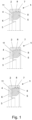
- the inner body 5 is held on the housing element 4 both force-fitting and form-fitting.
- the axial flange 7 of the housing element 4 is provided with form-locking elements 8 on the side facing the inner body 5 and the inner body 5 is provided with form-locking elements 8 on its outer circumference.
- the inner body 5 has annular, sawtooth-shaped elevations that engage in congruently shaped recesses that are made in the axial flange 7.
- the inner body 5 has rectangular elevations that engage in congruently shaped recesses that are made in the axial flange 7.
- the inner body 5 has semicircular elevations that engage in congruently shaped recesses that are made in the axial flange 7.
- the radial flange 6 of the housing element 4 and the inner body 5 are provided with a wave-shaped profile 11 on the sides facing each other, so that the sealing body 3 is deformed in a wave-shaped manner in this area.
- the sealing body 3 is designed as a sealing disc.
- the sealing disc is made of PTFE-impregnated Nonwoven fabric.
- the sealing body 3 is made of textile sheet material.
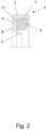
- Figure 2 shows a non-inventive alternative embodiment of the sealing ring 1 according to Figure 1 , in which the inner body 5 is connected to the housing element 4 via a thread.
- Figure 3 shows a non-inventive alternative embodiment of the sealing ring 1 according to Figure 1 , in which the sealing body 3 has a disc-shaped fastening section 9 and an elastomeric sealing lip 10.
- the disc-shaped section 9 and the elastomeric sealing lip 10 are made of different materials and are integrally bonded to one another.
- the sealing lip 10 is provided with an annular coil spring 14.
- Figure 4 shows a sealing ring 1 according to the invention according to Figure 1 , in which sealing elements 12 are arranged between the inner body 5, the sealing body 3, and the housing element 4.
- the sealing elements 12 are shaped as O-rings.
- Figure 5 shows sealing rings 1 according to the invention according to Figure 1 , which are additionally provided with a static seal 13.
- the static seal 13 is in the form of a form-fitting element.
- the static seal 13 is in the form of a separate sealing element, here in the form of an O-ring.
- the static seal 13 is in the form of a sealing varnish applied to the outer circumference of the housing element 4.
- Figure 6 shows a sealing ring 1 according to Figure 1 , in which the inner body 5 is held firmly to the housing element 4.
- the inner body 5 is welded by means of a welded connection 15 in the area of axial flange 7 and the outer circumference of the inner body 5 are connected to the housing element 4.
- Figure 7 shows a non-inventive sealing ring 1 according to Figure 1 , wherein a sliding bearing 16 in the form of a sliding ring is formed from the inner body 5, which projects radially inwards.
- the sliding bearing 16 shown can in principle be used in all previously shown configurations, in particular in the configurations according to Figures 1 to 5 be provided.
- Figure 8 shows a non-inventive sealing ring 1 according to Figure 1 , in which an adapter ring is arranged on the outer circumference of the housing element 4. The adapter ring is held force-fittingly on the housing element 4.
- Figure 9 shows a sealing ring 1 not according to the invention, comprising a support body 2 and a sealing body 3.
- the support body 2 has a housing element 4 made of plastic.
- the housing element 4 has a radial flange 6 and an axial flange 7.
- the sealing body 3 is firmly attached to the end face of the radial flange 6 facing the axial flange 7.
- the firmly attached connection is designed as a welded joint and was produced by friction welding.
- the sealing body 3 is firmly attached to the end face of the radial flange 6 facing away from the axial flange 7 and extends in sections over the axial flange 7 in order to form a static seal there.
- the sealing body 3 is designed as a sealing disc.
- the sealing disc in turn, is made of PTFE-impregnated nonwoven fabric. Therefore, the sealing body 3 is made of a textile fabric.
- the supporting body 2 is made of injection-moldable plastic.
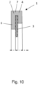
- Figure 10 shows a non-inventive development of the Figure 9 shown sealing ring 1.
- the axial flange 7 was plastically deformed after insertion of the sealing body 3, so that the sealing body 3 borders on the housing element 4 on both end faces.
- the sealing body 3 is positively integrated into the housing element 4.
- the plastic deformation of the housing element 4 can be achieved by briefly heating it above the melting point of the plastic used for the housing element 4.
- Figure 11 shows a non-inventive, alternative embodiment of the Figure 10 shown sealing ring 1.
- the sealing body 3 has elevations 17 on both end faces, which improve the positive integration of the sealing body 3 into the housing element 4.
- Figure 12 shows a sealing ring 1 not according to the invention, comprising a support body 2 and a sealing body 3.
- the support body 2 has a housing element 4 made of plastic.
- the housing element 4 has a radial flange 6 and an axial flange 7.
- the sealing body 3 is positively fastened to the end face of the radial flange 6 facing away from the axial flange 7.
- the positive connection is made via push-button-like projections 18, which protrude through openings 19 made in the sealing body 3, wherein the projections 18 engage in a locking element 20.
- the sealing body 3 can extend in sections over the axial flange 7 in order to form a static seal there.
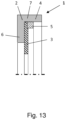
- Figure 13 shows a non-inventive embodiment of a sealing ring 1, comprising a support body 2 and a sealing body 3.
- the support body 2 is formed in several parts and has a housing element 4 formed from plastic and an inner body 5 formed from plastic.
- the housing element 4 has a radial flange 6 and an axial flange 7 and the housing element 4 accommodates the inner body 5 and the sealing body 3 arranged between the radial flange 6 and the inner body 5.
- the inner body 5 is held firmly to the housing element 4.
- the firmly bonded connection is formed as a welded joint, but can also be an adhesive connection. After positioning the sealing body 3, the inner body 5 is inserted into the housing element 4, for example, bonded firmly to the housing element 4 by friction welding.
- the inner body 5 deforms during the joining process and thereby clamps the sealing body 3.
- the sealing body 3 is designed as a sealing disc.
- the sealing disc in turn, is made of PTFE-impregnated nonwoven fabric. Therefore, the sealing body 3 is made of a textile fabric.
- the sealing rings 1 shown in the figures described above are particularly suitable for use in devices with plastic housings, for example, in handheld tools for DIY and household appliances.
- the sealing ring 1 is suitable for sealing shafts that protrude from the plastic housing.
- An advantageous device comprises a plastic housing in which a shaft is mounted, wherein in the gap between the plastic housing and the shaft a sealing ring 1 according to one of the Figures 1 to 13 shown designs.
Landscapes
- Engineering & Computer Science (AREA)
- General Engineering & Computer Science (AREA)
- Mechanical Engineering (AREA)
- Sealing With Elastic Sealing Lips (AREA)
- Sealing Devices (AREA)
- Gasket Seals (AREA)
Description
- Die Erfindung betrifft einen Dichtring, umfassend einen Tragkörper und zumindest einen Dichtkörper.
- Bei elektrischen Kleingeräten, beispielsweise bei Haushaltsgeräten, werden zur Abdichtung häufig einfachste Dichtsysteme zum Einsatz gebracht. Hierbei ist eine wesentliche Anforderung, dass diese kostengünstig sein müssen. Dabei werden Dichtelemente häufig direkt in Gehäuseteile der Kleingeräte integriert. Eine Austauschmöglichkeit derartiger Dichtelemente ist nicht vorgesehen. Die Dichtelemente sind darüber hinaus häufig von minderwertiger Qualität, so dass die Dichtwirkung des Dichtsystems nicht über die geplante Nutzungsdauer des Kleingerätes aufrechterhalten werden kann. Ein Einsatz von Dichtelementen wie sie in der Industrie üblich sind, scheidet dabei aufgrund der hohen Materialkosten für Dichtelement und Tragkörper aus.
- Aus der
GB 2 272 733 A - Der Erfindung liegt die Aufgabe zugrunde, einen Dichtring bereitzustellen, der besonders kostengünstig ist und dabei eine Dichtwirkung über einen langen Gebrauchszeitraum ermöglicht.
- Diese Aufgabe wird mit den Merkmalen von Anspruch 1 gelöst. Auf vorteilhafte Ausgestaltungen nehmen die Unteransprüche Bezug.
- Zur Lösung der Aufgabe umfasst der Dichtring einen Tragkörper und zumindest einen Dichtkörper, wobei der Tragkörper zumindest ein aus Kunststoff ausgebildetes Gehäuseelement aufweist, wobei das Gehäuseelement einen Radialflansch und einen Axialflansch aufweist und wobei das Gehäuseelement den Dichtkörper aufnimmt.
- Der Dichtkörper kann stoffschlüssig an das Gehäuseelement angebunden sein. Ein derartiger Dichtring ist einfach und kostengünstig herstellbar. Durch den Stoffschluss sind der Dichtkörper und das Gehäuseelement verliersicher miteinander verbunden. Dichtkörper und Gehäuseelement können besonders einfach geformt sein. Die stoffschlüssige Verbindung kann über ein Klebemittel hergestellt werden. Vorzugsweise ergibt sich die stoffschlüssige Verbindung durch stellenweises Aufschmelzen des Kunststoffes, beispielsweise durch eine Schweißverbindung. Diese kann beispielsweise mittels Reibschweißen hergestellt sein.
- Der Dichtkörper kann formschlüssig an das Gehäuseelement angebunden sein. Bei einer formschlüssigen Verbindung entfallen die Verfahrensschritte die für eine stoffschlüssige Verbindung erforderlich sind. Des Weiteren entfällt eine Vorbehandlung der Fügestellen mit problematischen Stoffen wie es für eine stoffschlüssige Klebeverbindung häufig erforderlich ist.
- Der Dichtkörper kann sich entlang der Stirnseite des Radialflansches und zumindest abschnittsweise entlang des Axialflansches des Gehäuseelementes erstrecken. Bei dieser Ausgestaltung fungiert der Dichtkörper als dynamische Abdichtung gegenüber einem abzudichtenden, rotierenden Maschinenelement, beispielsweise einer Welle und als statische Abdichtung gegenüber einem weiteren abzudichtenden Maschinenelement, beispielsweise einem Gehäuse. Dabei kann der Dichtkörper kompressibel ausgebildet sein und dadurch die Klemmwirkung des Dichtringes in dem Gehäuse verstärken. Des Weiteren schirmt der Dichtkörper das Gehäuseelement auf einer Seite des Spaltes zwischen den beiden Maschinenelementen ab.
- Der Tragkörper ist erfindungsgemäß mehrteilig ausgebildet und weist einen aus Kunststoff ausgebildeten Innenkörper auf, wobei das Gehäuseelement den Innenkörper und den zwischen Radialflansch und Innenkörper angeordneten Dichtkörper aufnimmt. Bei dieser Ausgestaltung ist der Dichtkörper zwischen dem Innenkörper und dem Gehäuseelement eingeklemmt und dadurch fixiert.
- Das Gehäuseelement kann als L-förmiger Ring ausgebildet sein. Der Innenkörper ist vorzugsweise ringförmig ausgebildet und gelangt nach Montage zur Anlage an dem Radialflansch und der der nach innen gerichteten Seite des Axialflansches. Bei dieser Ausgestaltung bildet der Innenkörper einen Klemmkörper.
- Dadurch, dass der Tragkörper, bzw. die Komponenten des Tragkörpers aus Kunststoff ausgebildet sind, ist der Tragkörper besonders kostengünstig herstellbar. Dabei ist besonders vorteilhaft, dass der Dichtkörper formschlüssig zwischen Innenkörper und Gehäuseelement gehalten ist. Dadurch ist es nicht erforderlich, das Material von Innenkörper und Gehäuseelement so auszubilden, dass eine stoffschlüssige Anbindung des Dichtkörpers an den Tragkörper möglich ist. Insofern können bei der erfindungsgemäßen Ausgestaltung beispielsweise Dichtkörper aus PTFE zum Einsatz gelangen, welche ausschließlich durch Formschluss zwischen dem Innenkörper und dem Gehäuseelement gehalten sind.
- Der Tragkörper kann dabei außenumfangsseitig oder entlang einer dem Gehäuse zugeordneten Stirnseite eine statische Dichtung ausbilden. Dabei kann die statische Dichtung bereits direkt durch den Tragkörper oder das Gehäuseelement realisiert sein. Insbesondere durch Wahl eines geeigneten Kunststoffs kann sich eine ausreichende Abdichtung zwischen Tragkörper und Gehäuse ergeben. Alternativ kann dem Gehäuseelement eine statische Dichtung aus abweichendem Material zugeordnet sein. Hierbei ist insbesondere denkbar, mittels Zweikomponentenspritzguss eine statische Dichtung aus thermoplastischem Material anzuformen.
- Als Material für den Innenkörper und das Gehäuseelement kommt vorzugsweise ein thermoplastischer Kunststoff zum Einsatz, so dass Innenkörper und Gehäuseelement im Spritzgießverfahren herstellbar sind. Je nach Einsatzzweck ist es hierbei denkbar, das Gehäuseelement und den Innenkörper aus Polyethylen (PE), Polyamid (PA), Polylactid (PLA), Polypropylen (PP), Polycarbonat (PC), Acrylnitril-Butadien-Styrol (ABS), Polymethylmethacrylat (PMMA), Polyethylenterephthalat (PET) oder Polytetrafluorethylen (PTFE) herzustellen. Des Weiteren ist denkbar, Gehäuseelement und Innenkörper aus einem Duromer auszubilden, wobei zusätzlich eine Faserverstärkung vorgesehen sein kann.
- Dabei ist insbesondere denkbar, Gehäuseelement und Innenkörper aus voneinander abweichenden Kunststoffen bereitzustellen. Dabei wird der Werkstoff des Gehäuseelementes so gewählt, dass dieser sicher in einer Gehäusebohrung fixierbar ist. Das Material für den Innenkörper kann so gewählt werden, dass sich eine besonders feste Verbindung von Gehäuseelement und Innenkörper ergibt. Des Weiteren kann für das Gehäuseelement auch ein vergleichsweise weicher Kunststoff gewählt werden, der eine besonders gute statische Abdichtung gegenüber dem Gehäuse ermöglicht.
- Der Innenkörper kann beispielsweise aus einem elastischen Werkstoff, beispielsweise einem elastomeren Werkstoff ausgebildet sein, so dass der Innenkörper mit elastischer Vorspannung in dem Gehäuseelement gehalten ist. Dadurch ergibt sich eine sichere Verbindung von Innenkörper, Dichtscheibe und Gehäuseelement.
- Der Innenkörper ist erfindungsgemäß formschlüssig an dem Gehäuseelement gehalten. Bei dieser Ausgestaltung weist zumindest der Innenumfang des Axialflansches und/oder der Außenumfang des Innenkörpers Formschlusselemente auf. Nach einer vorteilhaften Ausgestaltung weist der Innenumfang des Axialflansches hierzu ringförmige Vertiefungen in Form einer Nut auf und der Innenkörper weist an seinem Umfang ringförmige Erhebungen auf, welche kongruent zu den Vertiefungen ausgebildet sind. Die Erhebungen und Vertiefungen können auch nur segmentweise ausgebildet sein. Nach Montage des Innenkörpers greifen die Erhebungen des Innenkörpers in die Vertiefungen des Axialflansches des Gehäuseelementes ein und fixieren so den Innenkörper formschlüssig und verliersicher in dem Gehäuseelement. Die Erhebungen können trapezförmig und insbesondere sägezahnförmig ausgebildet sein.
- Weitere Möglichkeiten der formschlüssigen Verbindung ergeben sich durch eine Schraubverbindung, bei welcher der Innenkörper ein Außengewinde und das Gehäuseelement ein Innengewinde aufweist, und durch einen Bajonett-Verschluss.
- Der Innenkörper kann kraftschlüssig an dem Gehäuseelement gehalten sein. Der Kraftschluss kann zusätzlich zu einem Formschluss realisiert werden. Dazu können der Innendurchmesser des Axialflansches ein Untermaß und/oder der Außendurchmesser des Innenkörpers ein Übermaß aufweisen. Dadurch kann der Innenkörper nur mit Kraftaufwand an, beziehungsweise in dem Gehäuseelement montiert werden. Nach Montage ist der Innenkörper kraftschlüssig an dem Gehäuseelement fixiert und klemmt dabei den Dichtkörper zwischen Innenkörper und Gehäuseelement ein. Insofern ist der Dichtkörper verliersicher zwischen Innenkörper und Gehäuseelement gehalten. Zur Erhöhung der Klemmwirkung können die einander berührenden Flächen von Innenkörper und Gehäuseelement aufgeraut sein.
- Der Innenkörper kann stoffschlüssig an dem Gehäuseelement gehalten sein. Der Stoffschluss kann zusätzlich zu dem Formschluss und/oder dem Kraftschluss vorgesehen sein. Hierbei ist es denkbar, dass der Innenkörper mittels einer Klebeverbindung oder einer Schweißverbindung an dem Gehäuseelement stoffschlüssig gehalten ist. Durch die stoffschlüssige Verbindung ergibt sich eine besonders feste Verbindung von Innenkörper und Gehäuseelement. Um die stoffschlüssige Verbindung von Innenkörper und Gehäuseelement herzustellen, sind dabei insbesondere die folgenden Verfahren denkbar: Kleben, Heißverstemmen, Heißelementschweißen, Hochfrequenzschweißen, Laserdurchstrahlschweißen, Zirkularschweißen, Rotationsreibschweißen, Ultraschallschweißen, Vibrationsschweißen und Warmgasschweißen. Bei den Schweißverfahren ist insbesondere vorteilhaft, dass diese eine stoffschlüssige Verbindung von Innenkörper und Gehäuseelement ohne Verwendung eines Zuschlagstoffes ermöglichen.
- Der Dichtkörper kann als Dichtscheibe ausgebildet sein. Ein derartiger Dichtkörper ist besonders einfach und kostengünstig herstellbar. Es ist beispielsweise denkbar, den Dichtkörper aus einem rohrförmigen Halbzeug kostengünstig herzustellen. Insbesondere wenn der Dichtkörper lediglich als Staubdichtung fungiert und das Eindringen von Verschmutzungen in einen abzudichtenden Raum verhindern soll, ist es zumeist ausreichend den Dichtkörper als Dichtscheibe auszubilden. In diesem Fall kann die Dichtscheibe beispielsweise aus Filz oder ähnlichem textilen Material bestehen. Für einfache Dichtungsaufgaben, bei welchen Fett zurückgehalten werden soll, kann die Dichtscheibe aus elastomerem Material ausgebildet sein.
- Nach einer vorteilhaften Ausgestaltung ist der Dichtkörper aus textilem Flächenmaterial ausgebildet. Ein derartiges textiles Flächenmaterial ist beispielsweise ein Vliesstoff in Form einer Bahnenware. Zur Erhöhung der Dichtwirkung kann das textile Flächenmaterial mit einer Imprägnierung aus PTFE versehen sein. Ein derartiges PTFE-Vlies weist eine hervorragende Dichtwirkung gegenüber eindringenden Verschmutzungen und Spritzwasser auf. Darüber hinaus weist ein PTFE-Vlies eine besonders geringe Reibung auf, so dass sich im laufenden Betrieb nur eine geringe Wärmeentwicklung im Bereich des Dichtrings ergibt. Dies ist insbesondere im Zusammenhang mit dem aus Kunststoff bestehenden Tragkörper vorteilhaft. Es ist auch denkbar einen beschichteten Vliesstoff einzusetzen. In einer weiteren Ausgestaltung kann das textile Flächenmaterial elektrisch leitfähig ausgebildet sein. Bei entsprechend leitfähiger Ausrüstung des Tragkörpers ist diese Ausgestaltung beispielsweise dann vorteilhaft, wenn statische Elektrizität abgeleitet werden soll. Sowohl der Tragkörper als auch der Dichtkörper können aus PTFE ausgebildet sein.
- Des Weiteren ist denkbar, den Dichtkörper aus Zellstoff, insbesondere Papier auszubilden. Derartige Werkstoffe sind beispielsweise im Zusammenhang mit Flachdichtungen bekannt. Der Dichtkörper kann auch aus organischem Flächenmaterial, beispielsweise Leder oder dergleichen ausgebildet sein.
- Sowohl der Tragkörper als auch der Dichtkörper kann Recycling-Material umfassen. Der Tragkörper kann ebenfalls aus nachwachsendem Rohstoff, beispielsweise Karton bestehen. Der Dichtkörper kann beispielsweise aus flächigem elastomerem Material hergestellt sein, welches bei der Produktion höherwertiger Dichtungen anfällt.
- Alternativ kann der Dichtkörper einen scheibenförmigen Befestigungsabschnitt und eine elastomere Dichtlippe aufweisen. Dabei kann sowohl der scheibenförmige Befestigungsabschnitt als auch die Dichtlippe aus demselben elastomeren Material bestehen und materialeinheitlich und einstückig ausgebildet sein. Alternativ kann der scheibenförmige Befestigungsabschnitt aus einem anderen Material als die Dichtlippe bestehen, wobei Befestigungsabschnitt und Dichtlippe dann stoffschlüssig miteinander verbunden sind. Die Dichtlippe kann so ausgebildet sein, dass diese unter radialer Vorspannung dichtend an dem abzudichtenden Maschinenelement anliegt. Zur Verstärkung der Dichtwirkung kann eine Ringfeder oder dergleichen vorgesehen sein. Insofern kann der Dichtring auch als Radialwellendichtring ausgebildet sein.
- Die Dichtlippe kann auf dem der Welle zugeordneten Abschnitt mit einer Profilierung, beispielsweise einer Drallnut versehen sein.
- Der Radialabschnitt des Gehäuseelementes kann auf der dem Innenkörper zugewandten Seite und/oder der Innenkörper kann auf der dem Radialabschnitt zugewandten Seite mit einer Profilierung versehen sein. Die Profilierung kann dabei aus kongruent zueinander ausgebildeten Erhebungen und Vertiefungen bestehen. Durch die Profilierung wird der zwischen Innenkörper und Gehäuseabschnitt angeordnete Dichtkörper abschnittsweise verformt, so dass sich die Klemmwirkung des Dichtkörpers in dem Tragkörper verbessert. Nach einer vorteilhaften Ausgestaltung ergibt sich eine wellenförmige Profilierung, so dass der Dichtkörper in diesem Bereich ebenfalls wellenförmig verformt und zwischen Gehäuseelement und Innenkörper eingeklemmt wird.
- Zwischen Innenkörper, Dichtkörper und Gehäuseelement sind erfindungsgemäß Dichtelemente angeordnet. Die zusätzlichen Dichtelemente können dabei beispielsweise in Form von O-Ringen ausgebildet sein. Die Dichtelemente, welche zwischen Innenkörper und Dichtkörper, beziehungsweise zwischen Dichtkörper und Gehäuseelement angeordnet sind, verbessern die Abdichtung des Dichtrings, so dass kein abzudichtendes Medium zwischen die Komponenten des Dichtrings gelangen kann.
- Der Dichtkörper kann stoffschlüssig an Innenkörper und/oder Gehäuseelement festgelegt sein. Dies kann mittels einer Klebe- oder Schweißverbindung und zusätzlich zu den zuvor beschriebenen Maßnahmen erfolgen. Durch die stoffschlüssige Anbindung kann die Gefahr einer statischen Leckage zwischen den Komponenten des Dichtrings vermindert werden.
- Dem Axialflansch kann außenumfangsseitig eine separate statische Dichtung zugeordnet sein. Dabei kann die statische Dichtung kraftschlüssig auf dem Außenumfang des Gehäuseelementes gehalten sein. Alternativ kann die statische Dichtung auch stoffschlüssig mit dem Gehäuseelement verbunden sein. Die statische Dichtung kann aus einem ringförmigen elastomeren Element bestehen, welches eine geringe Wandstärke aufweist. Alternativ ist es denkbar, die statische Dichtung in Form eines Dichtlacks auszubilden, welcher im Sprühverfahren auf das Gehäuseelement aufgetragen wird.
- Dem Dichtring kann ein Gleitlager zugeordnet sein, auf welchem sich die Welle zur Entlastung des Dichtkörpers abstützen kann.
- Der erfindungsgemäße Dichtring eignet sich insbesondere für den Einsatz in Elektrokleingeräten. Eine erfindungsgemäße Dichtungsanordnung umfasst ein Elektrokleingerät und einen Dichtring, wobei das Elektrokleingerät ein Gehäuse aufweist, aus welcher eine Welle herausragt und wobei der Dichtring in dem Spalt zwischen Gehäuse und Welle angeordnet ist und in dem Gehäuse fixiert ist. Bei dem Elektrokleingerät kann es sich um ein Haushaltsgerät, beispielsweise um eine Fruchtpresse, einen Mixer, einen Pürierstab oder eine Küchenmaschine handeln. Ferner ist denkbar, dass das Elektrokleingerät ein Elektrowerkzeug ist.
- Dem Tragkörper kann ein Adapterring zugeordnet sein. Dieser ist vorzugsweise kraftschlüssig dem Außenumfang des Gehäuseelementes zugeordnet. Durch den Adapterring kann das Gehäuseelement an verschiedene Durchmesser der Aufnahmebohrung des Gehäuses, in welchem der Dichtring montiert werden soll, angepasst werden. Der Adapterring besteht ebenfalls aus Kunststoff. Der Adapterring kann formschlüssig mittels entsprechender Profilierungen, kraftschlüssig und/oder stoffschlüssig mittels einer Klebe- oder Schweißverbindung auf dem Außenumfang des Gehäuseelementes befestigt sein.
- Aus dem Gehäuseelement kann auch ein Flansch ausgebildet sein. Der Flansch kann ringförmig ausgebildet sein und radial nach außen von dem Dichtring abstehen. Mittels des Flansches kann der Dichtring an einem Gehäuse fixiert werden. Der Flansch kann Durchbrüche für Befestigungsmittel aufweisen.
- Dem Dichtring kann ein Sensor zugeordnet sein. Dabei kann der Sensor zwischen Innenkörper und Gehäuseelement angeordnet sein und dort zusammen mit dem Dichtkörper eingeklemmt sein. Alternativ kann der Sensor auch dem Innenkörper und/oder dem Gehäuseelement zugeordnet sein. Es ist auch denkbar, den Sensor innerhalb des Innenkörpers oder des Gehäuseelementes anzuordnen. Der Sensor kann beispielsweis die Temperatur von Gehäuse oder Wellen, die Drehzahl der Welle oder in den Dichtring eindringendes Medium erfassen.
- Einige Ausgestaltungen des erfindungsgemäßen Dichtrings werden nachfolgend anhand der Figuren näher erläutert. Diese zeigen, jeweils schematisch:
- Fig. 1
- Dichtringe mit Dichtscheibe im Schnitt;
- Fig. 2
- einen Dichtring mit Dichtscheibe im Schnitt;
- Fig. 3
- einen Dichtring mit Dichtlippe im Schnitt;
- Fig. 4
- einen Dichtring mit Dichtelementen;
- Fig. 5
- Dichtringe mit statischer Dichtung;
- Fig. 6
- einen Dichtring mit Stoffschluss zwischen Gehäuseelement und Innenkörper;
- Fig. 7
- einen Dichtring mit integriertem Gleitlager;
- Fig. 8
- einen Dichtring mit Adapterring;
- Fig. 9
- einen Dichtring mit stoffschlüssig an dem Tragkörper angebundenen Dichtkörper;
- Fig. 10
- einen Dichtring mit formschlüssig eingebundenem Dichtkörper;
- Fig. 11
- einen Dichtring mit formschlüssig eingebundenem Dichtkörper;
- Fig. 12
- einen Dichtring mit formschlüssig an dem Tragkörper angeordneten Dichtkörper;
- Fig. 13
- einen Dichtring dessen Tragkörper ein Gehäuseelement und einen Innenkörper aufweist.
- Bei den Ausgestaltungen ist der Innenkörper 5 sowohl kraftschlüssig als auch formschlüssig an dem Gehäuseelement 4 gehalten.
- Dazu sind der Axialflansch 7 des Gehäuseelements 4 auf der dem Innenkörper 5 zugewandten Seite und der Innenkörper 5 auf dessen Außenumfang mit Formschlusselementen 8 versehen. Bei der ersten Ausgestaltung weist der Innenkörper 5 dazu ringförmige sägezahnförmige Erhebungen auf, welche in kongruent geformte Vertiefungen eingreifen, die in den Axialflansch 7 eingebracht sind. Bei der zweiten Ausgestaltung weist der Innenkörper 5 rechteckförmige Erhebungen auf, welche in kongruent geformte Vertiefungen eingreifen, die in den Axialflansch 7 eingebracht sind. Bei der dritten Ausgestaltung weist der Innenkörper 5 halbrunde Erhebungen auf, welche in kongruent geformte Vertiefungen eingreifen, die in den Axialflansch 7 eingebracht sind.
- Der Radialflansch 6 des Gehäuseelements 4 und der Innenkörper 5 sind an den einander zugewandten Seiten mit einer wellenförmigen Profilierung 11 versehen, so dass der Dichtkörper 3 in diesem Bereich wellenförmig verformt wird.
- Bei der Ausgestaltung gemäß
Figur 1 ist der Dichtkörper 3 als Dichtscheibe ausgebildet. Die Dichtscheibe ist wiederum aus mit PTFE getränktem Vliesstoff ausgebildet. Insofern ist der Dichtkörper 3 aus textilem Flächenmaterial ausgebildet. -
Figur 2 zeigt eine nicht-erfindungsgemäße alternative Ausgestaltung des Dichtrings 1 gemäßFigur 1 , bei welchem der Innenkörper 5 über ein Gewinde mit dem Gehäuseelement 4 verbunden ist. -
Figur 3 zeigt eine nicht-erfindungsgemäße alternative Ausgestaltung des Dichtrings 1 gemäßFigur 1 , bei welchem der Dichtkörper 3 einen scheibenförmigen Befestigungsabschnitt 9 und eine elastomere Dichtlippe 10 aufweist. Der scheibenförmige Abschnitt 9 und die elastomere Dichtlippe 10 bestehen aus voneinander abweichendem Material und sind stoffschlüssig miteinander verbunden. Die Dichtlippe 10 ist mit einer Ringwendelfeder 14 versehen. -
Figur 4 zeigt einen erfindungsgemäßen Dichtring 1 gemäßFigur 1 , bei welchem zwischen Innenkörper 5, Dichtkörper 3 und Gehäuseelement 4 Dichtelemente 12 angeordnet sind. Die Dichtelemente 12 sind als O-Ringe geformt. -
Figur 5 zeigt erfindungsgemäße Dichtringe 1 gemäßFigur 1 , welche zusätzlich mit einer statischen Dichtung 13 versehen sind. Bei der ersten Ausgestaltung liegt die statische Dichtung 13 in Form eines Formschlusselementes vor. Bei der zweiten Ausgestaltung liegt die statische Dichtung 13 in Form eines separaten Dichtelementes, hier in Form eines O-Ringes vor. Bei der dritten Ausgestaltung liegt die statische Dichtung 13 in Form eines auf dem Außenumfang des Gehäuseelementes 4 aufgebrachten Dichtlacks vor. -
Figur 6 zeigt einen Dichtring 1 gemäßFigur 1 , bei welchem der Innenkörper 5 stoffschlüssig an dem Gehäuseelement 4 gehalten ist. Dazu ist der Innenkörper 5 mittels einer Schweißverbindung 15 im Bereich des Axialflansches 7 und des Außenumfangs des Innenkörpers 5 an dem Gehäuseelement 4 angebunden. -
Figur 7 zeigt einen nicht-erfindungsgemäßen Dichtring 1 gemäßFigur 1 , wobei aus dem Innenkörper 5 ein Gleitlager 16 in Form eines Gleitrings ausgebildet ist, welches radial nach innen ragt. Das inFigur 7 gezeigte Gleitlager 16 kann grundsätzlich in allen zuvor gezeigten Ausgestaltungen, insbesondere in den Ausgestaltungen gemäß derFiguren 1 bis 5 vorgesehen sein. -
Figur 8 zeigt einen nicht-erfindungsgemäßen Dichtring 1 gemäßFigur 1 , bei welchem auf dem Außenumfang des Gehäuseelementes 4 ein Adapterring angeordnet ist. Der Adapterring ist kraftschlüssig auf dem Gehäuseelement 4 gehalten. -
Figur 9 zeigt einen nicht-erfindungsgemäßen Dichtring 1, umfassend einen Tragkörper 2 und einen Dichtkörper 3. Der Tragkörper 2 weist ein aus Kunststoff ausgebildetes Gehäuseelement 4 auf. Dabei weist das Gehäuseelement 4 einen Radialflansch 6 und einen Axialflansch 7 auf. Der Dichtkörper 3 ist auf der dem Axialflansch 7 zugewandten Stirnseite des Radialflansches 6 stoffschlüssig befestigt. Die stoffschlüssige Verbindung ist als Schweißverbindung ausgebildet und wurde mittels Reibschweißen hergestellt. - Gemäß einer alternativen Ausgestaltung ist der Dichtkörper 3 auf der dem Axialflansch 7 abgewandten Stirnseite des Radialflansches 6 stoffschlüssig befestigt und erstreckt sich abschnittsweise über den Axialflansch 7, um dort eine statische Abdichtung zu bilden.
- Der Dichtkörper 3 ist als Dichtscheibe ausgebildet. Die Dichtscheibe ist wiederum aus mit PTFE getränktem Vliesstoff ausgebildet. Insofern ist der Dichtkörper 3 aus textilem Flächenmaterial ausgebildet. Der Tragkörper 2 besteht aus spritzgießfähigem Kunststoff.
-
Figur 10 zeigt eine nicht-erfindungsgemäße Weiterbildung des inFigur 9 gezeigten Dichtringes 1. Bei dieser Ausgestaltung wurde der Axialflansch 7 nach Einlegen des Dichtkörpers 3 plastisch verformt, so dass der Dichtkörper 3 an beiden Stirnseiten an das Gehäuseelement 4 angrenzt. Dadurch ist der Dichtkörper 3 formschlüssig in das Gehäuseelement 4 eingebunden. Das plastische Verformen des Gehäuseelementes 4 kann durch kurzzeitiges Erwärmen über den Schmelzpunkt des für das Gehäuseelement 4 verwendeten Kunststoffes hinaus erfolgen. -
Figur 11 zeigt eine nicht-erfindungsgemäße, alternative Ausgestaltung des inFigur 10 gezeigten Dichtringes 1. Bei dieser Ausgestaltung weist der Dichtkörper 3 an den beiden Stirnseiten Erhebungen 17 auf, welche eine Verbesserung der formschlüssigen Einbindung des Dichtkörpers 3 in das Gehäuseelement 4 bewirken. -
Figur 12 zeigt einen nicht-erfindungsgemäßen Dichtring 1, umfassend einen Tragkörper 2 und einen Dichtkörper 3. Der Tragkörper 2 weist ein aus Kunststoff ausgebildetes Gehäuseelement 4 auf. Dabei weist das Gehäuseelement 4 einen Radialflansch 6 und einen Axialflansch 7 auf. Der Dichtkörper 3 ist auf der dem Axialflansch 7 abgewandten Stirnseite des Radialflansches 6 formschlüssig befestigt. Die formschlüssige Verbindung erfolgt über druckknopfähnliche Vorsprünge 18, welche durch in den Dichtkörper 3 eingebrachte Durchbrechungen 19 hindurchragen, wobei die Vorsprünge 18 in ein Verriegelungselement 20 einrasten. - Bei dieser Ausgestaltung kann sich der Dichtkörper 3 abschnittsweise über den Axialflansch 7 erstrecken, um dort eine statische Abdichtung zu bilden.
-
Figur 13 zeigt eine nicht-erfindungsgemäße Ausgestaltung eines Dichtrings 1, umfassend einen Tragkörper 2 und einen Dichtkörper 3. Der Tragkörper 2 ist mehrteilig ausgebildet und weist ein aus Kunststoff ausgebildetes Gehäuseelement 4 und einen aus Kunststoff ausgebildeten Innenkörper 5 auf. - Dabei weist das Gehäuseelement 4 einen Radialflansch 6 und einen Axialflansch 7 auf und das Gehäuseelement 4 nimmt den Innenkörper 5 und den zwischen Radialflansch 6 und Innenkörper 5 angeordneten Dichtkörper 3 auf.
- Bei den Ausgestaltungen ist der Innenkörper 5 stoffschlüssig an dem Gehäuseelement 4 gehalten. Die stoffschlüssige Verbindung ist als Schweißverbindung ausgebildet, kann aber auch eine Klebeverbindung sein. Nach Positionieren des Dichtkörpers 3 wird der Innenkörper 5 in das Gehäuseelement 4 eingelegt, beispielsweise mittels Reibschweißen stoffschlüssig an das Gehäuseelement 4 angebunden.
- Alternativ ist auch denkbar, dass sich der Innenkörper 5 während des Fügevorgangs verformt und dadurch den Dichtkörper 3 einklemmt.
- Der Dichtkörper 3 ist als Dichtscheibe ausgebildet. Die Dichtscheibe ist wiederum aus mit PTFE getränktem Vliesstoff ausgebildet. Insofern ist der Dichtkörper 3 aus textilem Flächenmaterial ausgebildet.
- Die in den zuvor beschriebenen Figuren gezeigten Dichtringe 1 eignen sich insbesondere für den Einsatz in Geräten mit Kunststoffgehäusen, beispielsweise in Handgeräten für den Heimwerkerbedarf und Haushaltsgeräten. Der Dichtring 1 eignet sich dabei zur Abdichtung von Wellen, welche aus dem Kunststoffgehäuse herausragen.
- Ein vorteilhaftes Gerät umfasst ein Kunststoffgehäuse, in welchem eine Welle gelagert ist, wobei in dem Spalt zwischen Kunststoffgehäuse und Welle ein Dichtring 1 gemäß einer der in den
Figuren 1 bis 13 gezeigten Ausgestaltungen ist.
Claims (8)
- Dichtring (1), umfassend einen Tragkörper (2) und zumindest einen Dichtkörper (3), wobei der Tragkörper (2) zumindest ein aus Kunststoff ausgebildetes Gehäuseelement (4) aufweist, wobei das Gehäuseelement (4) einen Radialflansch (6) und einen Axialflansch (7) aufweist und wobei das Gehäuseelement (4) den Dichtkörper (3) aufnimmt, wobei der Tragkörper (2) mehrteilig ausgebildet ist und einen aus Kunststoff ausgebildeten Innenkörper (5) aufweist, wobei das Gehäuseelement (4) den Innenkörper (5) und den zwischen Radialflansch (6) und Innenkörper (5) angeordneten Dichtkörper (3) aufnimmt, wobei der Innenkörper (5) formschlüssig an dem Gehäuseelement (4) gehalten ist, wobei der Axialflansch (7) des Gehäuseelements (4) auf der dem Innenkörper (5) zugewandten Seite mit Formschlusselementen (8) versehen ist, dadurch gekennzeichnet, dass zwischen dem Radialflansch (6) des Gehäuseelementes (4) und dem Dichtkörper (3) sowie zwischen dem Dichtkörper (3) und dem Innenkörper (5) Dichtelemente (12) angeordnet sind.
- Dichtring nach Anspruch 1, dadurch gekennzeichnet, dass der Innenkörper (5) kraftschlüssig an dem Gehäuseelement (4) gehalten ist.
- Dichtring nach einem der Ansprüche 1 bis 2, dadurch gekennzeichnet, dass der Innenkörper (5) stoffschlüssig an dem Gehäuseelement (4) gehalten ist.
- Dichtring nach Anspruch 3, dadurch gekennzeichnet, dass der Innenkörper (5) mittels einer Schweißverbindung an dem Gehäuseelement (4) angebunden ist.
- Dichtring nach einem der Ansprüche 1 bis 4, dadurch gekennzeichnet, dass der Dichtkörper (3) als Dichtscheibe ausgebildet ist.
- Dichtring nach einem der Ansprüche 1 bis 5, dadurch gekennzeichnet, dass der Dichtkörper (3) einen scheibenförmigen Befestigungsabschnitt (9) und eine elastomere Dichtlippe (10) aufweist.
- Dichtring nach einem der Ansprüche 1 bis 6, dadurch gekennzeichnet, dass der Dichtkörper (3) aus textilem Flächenmaterial ausgebildet ist.
- Dichtring nach einem der Ansprüche 1 bis 7, dadurch gekennzeichnet, dass dem Axialflansch (7) außenumfangsseitig eine statische Dichtung (13) zugeordnet ist.
Applications Claiming Priority (2)
| Application Number | Priority Date | Filing Date | Title |
|---|---|---|---|
| DE102017005284 | 2017-06-02 | ||
| PCT/EP2018/064215 WO2018220031A1 (de) | 2017-06-02 | 2018-05-30 | Dichtring |
Publications (2)
| Publication Number | Publication Date |
|---|---|
| EP3631254A1 EP3631254A1 (de) | 2020-04-08 |
| EP3631254B1 true EP3631254B1 (de) | 2025-04-30 |
Family
ID=62455513
Family Applications (1)
| Application Number | Title | Priority Date | Filing Date |
|---|---|---|---|
| EP18728152.2A Active EP3631254B1 (de) | 2017-06-02 | 2018-05-30 | Dichtring |
Country Status (6)
| Country | Link |
|---|---|
| EP (1) | EP3631254B1 (de) |
| KR (1) | KR102339750B1 (de) |
| CN (1) | CN110662914B (de) |
| ES (1) | ES3034907T3 (de) |
| HU (1) | HUE072147T2 (de) |
| WO (1) | WO2018220031A1 (de) |
Families Citing this family (3)
| Publication number | Priority date | Publication date | Assignee | Title |
|---|---|---|---|---|
| DE102018124256B4 (de) | 2018-10-01 | 2020-04-23 | Carl Freudenberg Kg | Dichtelement |
| DE102018124257A1 (de) | 2018-10-01 | 2020-04-02 | Carl Freudenberg Kg | Dichtelement |
| DE102021120283A1 (de) * | 2021-08-04 | 2023-02-09 | Carl Freudenberg Kg | Dichtring |
Citations (1)
| Publication number | Priority date | Publication date | Assignee | Title |
|---|---|---|---|---|
| GB2272733A (en) * | 1992-11-24 | 1994-05-25 | Dowty Seals Ltd | Annular seals |
Family Cites Families (8)
| Publication number | Priority date | Publication date | Assignee | Title |
|---|---|---|---|---|
| US3717351A (en) * | 1971-04-19 | 1973-02-20 | Microdt Inc | Seal |
| DE3402109C2 (de) * | 1984-01-21 | 1987-01-08 | Fa. Carl Freudenberg, 6940 Weinheim | Dichtung |
| DE474950T1 (de) * | 1990-09-14 | 1992-07-23 | W.S. Shamban Europa A/S, Helsingoer | Dichtungsvorrichtung und verfahren zu ihrer herstellung. |
| DE10148715B4 (de) * | 2001-10-02 | 2007-10-25 | Carl Freudenberg Kg | Radialwellendichtung und Verfahren zu ihrer Herstellung |
| JP2007298143A (ja) | 2006-05-02 | 2007-11-15 | Nok Corp | オイルシール |
| DE102009021892B4 (de) * | 2008-06-11 | 2019-10-10 | Schaeffler Technologies AG & Co. KG | Hochdruckwellenabdichtungsvorrichtung und hydraulisch mittels eines Pedals betätigbare Kupplung mit dieser Hochdruckwellenabdichtungsvorrichtung |
| DE102009028131A1 (de) | 2009-07-30 | 2011-02-03 | Trelleborg Sealing Solutions Germany Gmbh | Dichtung und Dichtungsanordnung |
| DE102012000184B4 (de) * | 2012-01-09 | 2015-02-05 | Carl Freudenberg Kg | Radialwellendichtring mit einer PTFE-Dichtlippe |
-
2018
- 2018-05-30 EP EP18728152.2A patent/EP3631254B1/de active Active
- 2018-05-30 ES ES18728152T patent/ES3034907T3/es active Active
- 2018-05-30 HU HUE18728152A patent/HUE072147T2/hu unknown
- 2018-05-30 KR KR1020197034908A patent/KR102339750B1/ko active Active
- 2018-05-30 CN CN201880034888.7A patent/CN110662914B/zh active Active
- 2018-05-30 WO PCT/EP2018/064215 patent/WO2018220031A1/de not_active Ceased
Patent Citations (1)
| Publication number | Priority date | Publication date | Assignee | Title |
|---|---|---|---|---|
| GB2272733A (en) * | 1992-11-24 | 1994-05-25 | Dowty Seals Ltd | Annular seals |
Also Published As
| Publication number | Publication date |
|---|---|
| ES3034907T3 (en) | 2025-08-26 |
| HUE072147T2 (hu) | 2025-10-28 |
| KR102339750B1 (ko) | 2021-12-14 |
| CN110662914A (zh) | 2020-01-07 |
| KR20190138878A (ko) | 2019-12-16 |
| CN110662914B (zh) | 2022-02-18 |
| EP3631254A1 (de) | 2020-04-08 |
| WO2018220031A1 (de) | 2018-12-06 |
Similar Documents
| Publication | Publication Date | Title |
|---|---|---|
| EP1585905B1 (de) | Dichtungsbaugruppe für eine lagerbüchse | |
| DE4436879A1 (de) | Dichtungseinheit, insbesondere für eine Wasserpumpe | |
| EP3047240A1 (de) | VERFAHREN ZUM HERSTELLEN EINER MAGNETEINHEIT FÜR EINE SENSOREINRICHTUNG ZUM ERFASSEN EINER EINEN ROTATIONSZUSTAND EINER LENKWELLE EINES KRAFTFAHRZEUGS CHARAKTERISIERENDEN MESSGRÖßE, MAGNETEINHEIT, SENSOREINRICHTUNG UND KRAFTFAHRZEUG | |
| DE10235079A1 (de) | Manschettendichtung | |
| WO2018220031A1 (de) | Dichtring | |
| DE202007018562U1 (de) | Dichtung | |
| WO2011009799A1 (de) | Öldrehdurchführung | |
| DE102018000935A1 (de) | Dichtungsanordnung | |
| DE102014100939A1 (de) | Waschaggregat für eine Waschmaschine | |
| BE1026281B1 (de) | Elektrischer Winkelsteckverbinder | |
| DE102015220151A1 (de) | Lageranordnung und Dichtung | |
| DE102012010789B4 (de) | Getriebe, umfassend zwei Gehäuseteile mit einer zwischengeordneten Dichtung | |
| EP1967780B1 (de) | Endanschlussmittel für ein Wellrohr | |
| EP1747384B1 (de) | Lageranordnung bestehend aus einem lager und einem lagerträger | |
| EP3728819B1 (de) | Dichtungsanordnung | |
| DE102020204244A1 (de) | Elektrische Maschine | |
| DE102016217069A1 (de) | Dichtungsanordnung eines Radlagers | |
| EP2256382B1 (de) | Dichtungsanordnung | |
| EP4130521A1 (de) | Dichtring | |
| EP4194721A1 (de) | Anordnung zur erdung eines maschinenelements | |
| DE102005030271B4 (de) | Dichtring, insbesondere Radialwellendichtring, sowie Verfahren zu seiner Herstellung | |
| EP1747941B1 (de) | Sensorhalterung zur Herstellung eines Sensors an einem Fahrzeugteil | |
| DE102016222412B4 (de) | Schmiermittelzuführbauteil | |
| DE1961014A1 (de) | Gehaeuse fuer Waelzlager | |
| AT522181A4 (de) | Dichtungsanordnung |
Legal Events
| Date | Code | Title | Description |
|---|---|---|---|
| STAA | Information on the status of an ep patent application or granted ep patent |
Free format text: STATUS: UNKNOWN |
|
| STAA | Information on the status of an ep patent application or granted ep patent |
Free format text: STATUS: THE INTERNATIONAL PUBLICATION HAS BEEN MADE |
|
| PUAI | Public reference made under article 153(3) epc to a published international application that has entered the european phase |
Free format text: ORIGINAL CODE: 0009012 |
|
| STAA | Information on the status of an ep patent application or granted ep patent |
Free format text: STATUS: REQUEST FOR EXAMINATION WAS MADE |
|
| 17P | Request for examination filed |
Effective date: 20191114 |
|
| AK | Designated contracting states |
Kind code of ref document: A1 Designated state(s): AL AT BE BG CH CY CZ DE DK EE ES FI FR GB GR HR HU IE IS IT LI LT LU LV MC MK MT NL NO PL PT RO RS SE SI SK SM TR |
|
| AX | Request for extension of the european patent |
Extension state: BA ME |
|
| DAV | Request for validation of the european patent (deleted) | ||
| DAX | Request for extension of the european patent (deleted) | ||
| STAA | Information on the status of an ep patent application or granted ep patent |
Free format text: STATUS: EXAMINATION IS IN PROGRESS |
|
| 17Q | First examination report despatched |
Effective date: 20220208 |
|
| GRAP | Despatch of communication of intention to grant a patent |
Free format text: ORIGINAL CODE: EPIDOSNIGR1 |
|
| STAA | Information on the status of an ep patent application or granted ep patent |
Free format text: STATUS: GRANT OF PATENT IS INTENDED |
|
| INTG | Intention to grant announced |
Effective date: 20241127 |
|
| GRAS | Grant fee paid |
Free format text: ORIGINAL CODE: EPIDOSNIGR3 |
|
| GRAA | (expected) grant |
Free format text: ORIGINAL CODE: 0009210 |
|
| STAA | Information on the status of an ep patent application or granted ep patent |
Free format text: STATUS: THE PATENT HAS BEEN GRANTED |
|
| AK | Designated contracting states |
Kind code of ref document: B1 Designated state(s): AL AT BE BG CH CY CZ DE DK EE ES FI FR GB GR HR HU IE IS IT LI LT LU LV MC MK MT NL NO PL PT RO RS SE SI SK SM TR |
|
| REG | Reference to a national code |
Ref country code: CH Ref legal event code: EP Ref country code: GB Ref legal event code: FG4D Free format text: NOT ENGLISH |
|
| REG | Reference to a national code |
Ref country code: IE Ref legal event code: FG4D Free format text: LANGUAGE OF EP DOCUMENT: GERMAN |
|
| REG | Reference to a national code |
Ref country code: DE Ref legal event code: R096 Ref document number: 502018015778 Country of ref document: DE |
|
| P01 | Opt-out of the competence of the unified patent court (upc) registered |
Free format text: CASE NUMBER: APP_19464/2025 Effective date: 20250423 |
|
| PGFP | Annual fee paid to national office [announced via postgrant information from national office to epo] |
Ref country code: DE Payment date: 20250528 Year of fee payment: 8 |
|
| PGFP | Annual fee paid to national office [announced via postgrant information from national office to epo] |
Ref country code: GB Payment date: 20250520 Year of fee payment: 8 Ref country code: ES Payment date: 20250611 Year of fee payment: 8 |
|
| PGFP | Annual fee paid to national office [announced via postgrant information from national office to epo] |
Ref country code: FR Payment date: 20250526 Year of fee payment: 8 |
|
| REG | Reference to a national code |
Ref country code: ES Ref legal event code: FG2A Ref document number: 3034907 Country of ref document: ES Kind code of ref document: T3 Effective date: 20250826 |
|
| REG | Reference to a national code |
Ref country code: NL Ref legal event code: MP Effective date: 20250430 |
|
| PG25 | Lapsed in a contracting state [announced via postgrant information from national office to epo] |
Ref country code: FI Free format text: LAPSE BECAUSE OF FAILURE TO SUBMIT A TRANSLATION OF THE DESCRIPTION OR TO PAY THE FEE WITHIN THE PRESCRIBED TIME-LIMIT Effective date: 20250430 Ref country code: PT Free format text: LAPSE BECAUSE OF FAILURE TO SUBMIT A TRANSLATION OF THE DESCRIPTION OR TO PAY THE FEE WITHIN THE PRESCRIBED TIME-LIMIT Effective date: 20250901 |
|
| REG | Reference to a national code |
Ref country code: LT Ref legal event code: MG9D |
|
| PG25 | Lapsed in a contracting state [announced via postgrant information from national office to epo] |
Ref country code: GR Free format text: LAPSE BECAUSE OF FAILURE TO SUBMIT A TRANSLATION OF THE DESCRIPTION OR TO PAY THE FEE WITHIN THE PRESCRIBED TIME-LIMIT Effective date: 20250731 Ref country code: NO Free format text: LAPSE BECAUSE OF FAILURE TO SUBMIT A TRANSLATION OF THE DESCRIPTION OR TO PAY THE FEE WITHIN THE PRESCRIBED TIME-LIMIT Effective date: 20250730 |
|
| PG25 | Lapsed in a contracting state [announced via postgrant information from national office to epo] |
Ref country code: PL Free format text: LAPSE BECAUSE OF FAILURE TO SUBMIT A TRANSLATION OF THE DESCRIPTION OR TO PAY THE FEE WITHIN THE PRESCRIBED TIME-LIMIT Effective date: 20250430 Ref country code: NL Free format text: LAPSE BECAUSE OF FAILURE TO SUBMIT A TRANSLATION OF THE DESCRIPTION OR TO PAY THE FEE WITHIN THE PRESCRIBED TIME-LIMIT Effective date: 20250430 |
|
| PGFP | Annual fee paid to national office [announced via postgrant information from national office to epo] |
Ref country code: IT Payment date: 20250721 Year of fee payment: 8 |
|
| PG25 | Lapsed in a contracting state [announced via postgrant information from national office to epo] |
Ref country code: BG Free format text: LAPSE BECAUSE OF FAILURE TO SUBMIT A TRANSLATION OF THE DESCRIPTION OR TO PAY THE FEE WITHIN THE PRESCRIBED TIME-LIMIT Effective date: 20250430 |
|
| PGFP | Annual fee paid to national office [announced via postgrant information from national office to epo] |
Ref country code: HU Payment date: 20250530 Year of fee payment: 8 |
|
| PG25 | Lapsed in a contracting state [announced via postgrant information from national office to epo] |
Ref country code: HR Free format text: LAPSE BECAUSE OF FAILURE TO SUBMIT A TRANSLATION OF THE DESCRIPTION OR TO PAY THE FEE WITHIN THE PRESCRIBED TIME-LIMIT Effective date: 20250430 |
|
| PG25 | Lapsed in a contracting state [announced via postgrant information from national office to epo] |
Ref country code: RS Free format text: LAPSE BECAUSE OF FAILURE TO SUBMIT A TRANSLATION OF THE DESCRIPTION OR TO PAY THE FEE WITHIN THE PRESCRIBED TIME-LIMIT Effective date: 20250731 |
|
| PGFP | Annual fee paid to national office [announced via postgrant information from national office to epo] |
Ref country code: CZ Payment date: 20250520 Year of fee payment: 8 |
|
| PG25 | Lapsed in a contracting state [announced via postgrant information from national office to epo] |
Ref country code: IS Free format text: LAPSE BECAUSE OF FAILURE TO SUBMIT A TRANSLATION OF THE DESCRIPTION OR TO PAY THE FEE WITHIN THE PRESCRIBED TIME-LIMIT Effective date: 20250830 |
|
| REG | Reference to a national code |
Ref country code: HU Ref legal event code: AG4A Ref document number: E072147 Country of ref document: HU |
|
| PG25 | Lapsed in a contracting state [announced via postgrant information from national office to epo] |
Ref country code: LV Free format text: LAPSE BECAUSE OF FAILURE TO SUBMIT A TRANSLATION OF THE DESCRIPTION OR TO PAY THE FEE WITHIN THE PRESCRIBED TIME-LIMIT Effective date: 20250430 |
|
| REG | Reference to a national code |
Ref country code: CH Ref legal event code: H13 Free format text: ST27 STATUS EVENT CODE: U-0-0-H10-H13 (AS PROVIDED BY THE NATIONAL OFFICE) Effective date: 20251223 |
|
| PG25 | Lapsed in a contracting state [announced via postgrant information from national office to epo] |
Ref country code: SM Free format text: LAPSE BECAUSE OF FAILURE TO SUBMIT A TRANSLATION OF THE DESCRIPTION OR TO PAY THE FEE WITHIN THE PRESCRIBED TIME-LIMIT Effective date: 20250430 Ref country code: DK Free format text: LAPSE BECAUSE OF FAILURE TO SUBMIT A TRANSLATION OF THE DESCRIPTION OR TO PAY THE FEE WITHIN THE PRESCRIBED TIME-LIMIT Effective date: 20250430 |
|
| PG25 | Lapsed in a contracting state [announced via postgrant information from national office to epo] |
Ref country code: LU Free format text: LAPSE BECAUSE OF NON-PAYMENT OF DUE FEES Effective date: 20250530 |
|
| PG25 | Lapsed in a contracting state [announced via postgrant information from national office to epo] |
Ref country code: CH Free format text: LAPSE BECAUSE OF NON-PAYMENT OF DUE FEES Effective date: 20250531 |
|
| PG25 | Lapsed in a contracting state [announced via postgrant information from national office to epo] |
Ref country code: EE Free format text: LAPSE BECAUSE OF FAILURE TO SUBMIT A TRANSLATION OF THE DESCRIPTION OR TO PAY THE FEE WITHIN THE PRESCRIBED TIME-LIMIT Effective date: 20250430 |
|
| PG25 | Lapsed in a contracting state [announced via postgrant information from national office to epo] |
Ref country code: RO Free format text: LAPSE BECAUSE OF FAILURE TO SUBMIT A TRANSLATION OF THE DESCRIPTION OR TO PAY THE FEE WITHIN THE PRESCRIBED TIME-LIMIT Effective date: 20250430 Ref country code: SK Free format text: LAPSE BECAUSE OF FAILURE TO SUBMIT A TRANSLATION OF THE DESCRIPTION OR TO PAY THE FEE WITHIN THE PRESCRIBED TIME-LIMIT Effective date: 20250430 |
|
| REG | Reference to a national code |
Ref country code: BE Ref legal event code: MM Effective date: 20250531 |
|
| PG25 | Lapsed in a contracting state [announced via postgrant information from national office to epo] |
Ref country code: MC Free format text: LAPSE BECAUSE OF FAILURE TO SUBMIT A TRANSLATION OF THE DESCRIPTION OR TO PAY THE FEE WITHIN THE PRESCRIBED TIME-LIMIT Effective date: 20250430 |
|
| REG | Reference to a national code |
Ref country code: DE Ref legal event code: R097 Ref document number: 502018015778 Country of ref document: DE |
|
| PLBE | No opposition filed within time limit |
Free format text: ORIGINAL CODE: 0009261 |
|
| STAA | Information on the status of an ep patent application or granted ep patent |
Free format text: STATUS: NO OPPOSITION FILED WITHIN TIME LIMIT |
|
| REG | Reference to a national code |
Ref country code: CH Ref legal event code: L10 Free format text: ST27 STATUS EVENT CODE: U-0-0-L10-L00 (AS PROVIDED BY THE NATIONAL OFFICE) Effective date: 20260311 |
|
| 26N | No opposition filed |
Effective date: 20260202 |
|
| PG25 | Lapsed in a contracting state [announced via postgrant information from national office to epo] |
Ref country code: IE Free format text: LAPSE BECAUSE OF NON-PAYMENT OF DUE FEES Effective date: 20250530 |
|
| PG25 | Lapsed in a contracting state [announced via postgrant information from national office to epo] |
Ref country code: BE Free format text: LAPSE BECAUSE OF NON-PAYMENT OF DUE FEES Effective date: 20250531 |