EP3631186B1 - Verfahren zur diagnose einer brennkraftmaschine eines kraftfahrzeuges, sowie der mit der brennkraftmaschine verbundenen vorrichtungen, sowie ein system zur durchführung des verfahrens - Google Patents
Verfahren zur diagnose einer brennkraftmaschine eines kraftfahrzeuges, sowie der mit der brennkraftmaschine verbundenen vorrichtungen, sowie ein system zur durchführung des verfahrens Download PDFInfo
- Publication number
- EP3631186B1 EP3631186B1 EP18726964.2A EP18726964A EP3631186B1 EP 3631186 B1 EP3631186 B1 EP 3631186B1 EP 18726964 A EP18726964 A EP 18726964A EP 3631186 B1 EP3631186 B1 EP 3631186B1
- Authority
- EP
- European Patent Office
- Prior art keywords
- exhaust gas
- internal combustion
- combustion engine
- obd
- value
- Prior art date
- Legal status (The legal status is an assumption and is not a legal conclusion. Google has not performed a legal analysis and makes no representation as to the accuracy of the status listed.)
- Active
Links
Images

Classifications
-
- F—MECHANICAL ENGINEERING; LIGHTING; HEATING; WEAPONS; BLASTING
- F02—COMBUSTION ENGINES; HOT-GAS OR COMBUSTION-PRODUCT ENGINE PLANTS
- F02D—CONTROLLING COMBUSTION ENGINES
- F02D41/00—Electrical control of supply of combustible mixture or its constituents
- F02D41/22—Safety or indicating devices for abnormal conditions
-
- F—MECHANICAL ENGINEERING; LIGHTING; HEATING; WEAPONS; BLASTING
- F01—MACHINES OR ENGINES IN GENERAL; ENGINE PLANTS IN GENERAL; STEAM ENGINES
- F01N—GAS-FLOW SILENCERS OR EXHAUST APPARATUS FOR MACHINES OR ENGINES IN GENERAL; GAS-FLOW SILENCERS OR EXHAUST APPARATUS FOR INTERNAL-COMBUSTION ENGINES
- F01N11/00—Monitoring or diagnostic devices for exhaust-gas treatment apparatus
- F01N11/007—Monitoring or diagnostic devices for exhaust-gas treatment apparatus the diagnostic devices measuring oxygen or air concentration downstream of the exhaust apparatus
-
- F—MECHANICAL ENGINEERING; LIGHTING; HEATING; WEAPONS; BLASTING
- F02—COMBUSTION ENGINES; HOT-GAS OR COMBUSTION-PRODUCT ENGINE PLANTS
- F02D—CONTROLLING COMBUSTION ENGINES
- F02D41/00—Electrical control of supply of combustible mixture or its constituents
- F02D41/02—Circuit arrangements for generating control signals
- F02D41/14—Introducing closed-loop corrections
- F02D41/1438—Introducing closed-loop corrections using means for determining characteristics of the combustion gases; Sensors therefor
- F02D41/1444—Introducing closed-loop corrections using means for determining characteristics of the combustion gases; Sensors therefor characterised by the characteristics of the combustion gases
-
- F—MECHANICAL ENGINEERING; LIGHTING; HEATING; WEAPONS; BLASTING
- F02—COMBUSTION ENGINES; HOT-GAS OR COMBUSTION-PRODUCT ENGINE PLANTS
- F02D—CONTROLLING COMBUSTION ENGINES
- F02D41/00—Electrical control of supply of combustible mixture or its constituents
- F02D41/02—Circuit arrangements for generating control signals
- F02D41/14—Introducing closed-loop corrections
- F02D41/1438—Introducing closed-loop corrections using means for determining characteristics of the combustion gases; Sensors therefor
- F02D41/1444—Introducing closed-loop corrections using means for determining characteristics of the combustion gases; Sensors therefor characterised by the characteristics of the combustion gases
- F02D41/1466—Introducing closed-loop corrections using means for determining characteristics of the combustion gases; Sensors therefor characterised by the characteristics of the combustion gases the characteristics being a soot concentration or content
-
- F—MECHANICAL ENGINEERING; LIGHTING; HEATING; WEAPONS; BLASTING
- F02—COMBUSTION ENGINES; HOT-GAS OR COMBUSTION-PRODUCT ENGINE PLANTS
- F02D—CONTROLLING COMBUSTION ENGINES
- F02D41/00—Electrical control of supply of combustible mixture or its constituents
- F02D41/22—Safety or indicating devices for abnormal conditions
- F02D41/222—Safety or indicating devices for abnormal conditions relating to the failure of sensors or parameter detection devices
-
- G—PHYSICS
- G01—MEASURING; TESTING
- G01M—TESTING STATIC OR DYNAMIC BALANCE OF MACHINES OR STRUCTURES; TESTING OF STRUCTURES OR APPARATUS, NOT OTHERWISE PROVIDED FOR
- G01M15/00—Testing of engines
- G01M15/04—Testing internal-combustion engines
- G01M15/10—Testing internal-combustion engines by monitoring exhaust gases or combustion flame
- G01M15/102—Testing internal-combustion engines by monitoring exhaust gases or combustion flame by monitoring exhaust gases
-
- F—MECHANICAL ENGINEERING; LIGHTING; HEATING; WEAPONS; BLASTING
- F01—MACHINES OR ENGINES IN GENERAL; ENGINE PLANTS IN GENERAL; STEAM ENGINES
- F01N—GAS-FLOW SILENCERS OR EXHAUST APPARATUS FOR MACHINES OR ENGINES IN GENERAL; GAS-FLOW SILENCERS OR EXHAUST APPARATUS FOR INTERNAL-COMBUSTION ENGINES
- F01N2550/00—Monitoring or diagnosing the deterioration of exhaust systems
-
- F—MECHANICAL ENGINEERING; LIGHTING; HEATING; WEAPONS; BLASTING
- F01—MACHINES OR ENGINES IN GENERAL; ENGINE PLANTS IN GENERAL; STEAM ENGINES
- F01N—GAS-FLOW SILENCERS OR EXHAUST APPARATUS FOR MACHINES OR ENGINES IN GENERAL; GAS-FLOW SILENCERS OR EXHAUST APPARATUS FOR INTERNAL-COMBUSTION ENGINES
- F01N2550/00—Monitoring or diagnosing the deterioration of exhaust systems
- F01N2550/02—Catalytic activity of catalytic converters
-
- F—MECHANICAL ENGINEERING; LIGHTING; HEATING; WEAPONS; BLASTING
- F01—MACHINES OR ENGINES IN GENERAL; ENGINE PLANTS IN GENERAL; STEAM ENGINES
- F01N—GAS-FLOW SILENCERS OR EXHAUST APPARATUS FOR MACHINES OR ENGINES IN GENERAL; GAS-FLOW SILENCERS OR EXHAUST APPARATUS FOR INTERNAL-COMBUSTION ENGINES
- F01N2550/00—Monitoring or diagnosing the deterioration of exhaust systems
- F01N2550/04—Filtering activity of particulate filters
-
- F—MECHANICAL ENGINEERING; LIGHTING; HEATING; WEAPONS; BLASTING
- F01—MACHINES OR ENGINES IN GENERAL; ENGINE PLANTS IN GENERAL; STEAM ENGINES
- F01N—GAS-FLOW SILENCERS OR EXHAUST APPARATUS FOR MACHINES OR ENGINES IN GENERAL; GAS-FLOW SILENCERS OR EXHAUST APPARATUS FOR INTERNAL-COMBUSTION ENGINES
- F01N2550/00—Monitoring or diagnosing the deterioration of exhaust systems
- F01N2550/05—Systems for adding substances into exhaust
-
- F—MECHANICAL ENGINEERING; LIGHTING; HEATING; WEAPONS; BLASTING
- F01—MACHINES OR ENGINES IN GENERAL; ENGINE PLANTS IN GENERAL; STEAM ENGINES
- F01N—GAS-FLOW SILENCERS OR EXHAUST APPARATUS FOR MACHINES OR ENGINES IN GENERAL; GAS-FLOW SILENCERS OR EXHAUST APPARATUS FOR INTERNAL-COMBUSTION ENGINES
- F01N2560/00—Exhaust systems with means for detecting or measuring exhaust gas components or characteristics
- F01N2560/02—Exhaust systems with means for detecting or measuring exhaust gas components or characteristics the means being an exhaust gas sensor
- F01N2560/021—Exhaust systems with means for detecting or measuring exhaust gas components or characteristics the means being an exhaust gas sensor for measuring or detecting ammonia NH3
-
- F—MECHANICAL ENGINEERING; LIGHTING; HEATING; WEAPONS; BLASTING
- F01—MACHINES OR ENGINES IN GENERAL; ENGINE PLANTS IN GENERAL; STEAM ENGINES
- F01N—GAS-FLOW SILENCERS OR EXHAUST APPARATUS FOR MACHINES OR ENGINES IN GENERAL; GAS-FLOW SILENCERS OR EXHAUST APPARATUS FOR INTERNAL-COMBUSTION ENGINES
- F01N2560/00—Exhaust systems with means for detecting or measuring exhaust gas components or characteristics
- F01N2560/02—Exhaust systems with means for detecting or measuring exhaust gas components or characteristics the means being an exhaust gas sensor
- F01N2560/025—Exhaust systems with means for detecting or measuring exhaust gas components or characteristics the means being an exhaust gas sensor for measuring or detecting O2, e.g. lambda sensors
-
- F—MECHANICAL ENGINEERING; LIGHTING; HEATING; WEAPONS; BLASTING
- F01—MACHINES OR ENGINES IN GENERAL; ENGINE PLANTS IN GENERAL; STEAM ENGINES
- F01N—GAS-FLOW SILENCERS OR EXHAUST APPARATUS FOR MACHINES OR ENGINES IN GENERAL; GAS-FLOW SILENCERS OR EXHAUST APPARATUS FOR INTERNAL-COMBUSTION ENGINES
- F01N2560/00—Exhaust systems with means for detecting or measuring exhaust gas components or characteristics
- F01N2560/02—Exhaust systems with means for detecting or measuring exhaust gas components or characteristics the means being an exhaust gas sensor
- F01N2560/026—Exhaust systems with means for detecting or measuring exhaust gas components or characteristics the means being an exhaust gas sensor for measuring or detecting NOx
-
- F—MECHANICAL ENGINEERING; LIGHTING; HEATING; WEAPONS; BLASTING
- F01—MACHINES OR ENGINES IN GENERAL; ENGINE PLANTS IN GENERAL; STEAM ENGINES
- F01N—GAS-FLOW SILENCERS OR EXHAUST APPARATUS FOR MACHINES OR ENGINES IN GENERAL; GAS-FLOW SILENCERS OR EXHAUST APPARATUS FOR INTERNAL-COMBUSTION ENGINES
- F01N2560/00—Exhaust systems with means for detecting or measuring exhaust gas components or characteristics
- F01N2560/05—Exhaust systems with means for detecting or measuring exhaust gas components or characteristics the means being a particulate sensor
-
- F—MECHANICAL ENGINEERING; LIGHTING; HEATING; WEAPONS; BLASTING
- F01—MACHINES OR ENGINES IN GENERAL; ENGINE PLANTS IN GENERAL; STEAM ENGINES
- F01N—GAS-FLOW SILENCERS OR EXHAUST APPARATUS FOR MACHINES OR ENGINES IN GENERAL; GAS-FLOW SILENCERS OR EXHAUST APPARATUS FOR INTERNAL-COMBUSTION ENGINES
- F01N2560/00—Exhaust systems with means for detecting or measuring exhaust gas components or characteristics
- F01N2560/06—Exhaust systems with means for detecting or measuring exhaust gas components or characteristics the means being a temperature sensor
-
- F—MECHANICAL ENGINEERING; LIGHTING; HEATING; WEAPONS; BLASTING
- F01—MACHINES OR ENGINES IN GENERAL; ENGINE PLANTS IN GENERAL; STEAM ENGINES
- F01N—GAS-FLOW SILENCERS OR EXHAUST APPARATUS FOR MACHINES OR ENGINES IN GENERAL; GAS-FLOW SILENCERS OR EXHAUST APPARATUS FOR INTERNAL-COMBUSTION ENGINES
- F01N2610/00—Adding substances to exhaust gases
- F01N2610/02—Adding substances to exhaust gases the substance being ammonia or urea
-
- F—MECHANICAL ENGINEERING; LIGHTING; HEATING; WEAPONS; BLASTING
- F01—MACHINES OR ENGINES IN GENERAL; ENGINE PLANTS IN GENERAL; STEAM ENGINES
- F01N—GAS-FLOW SILENCERS OR EXHAUST APPARATUS FOR MACHINES OR ENGINES IN GENERAL; GAS-FLOW SILENCERS OR EXHAUST APPARATUS FOR INTERNAL-COMBUSTION ENGINES
- F01N2900/00—Details of electrical control or of the monitoring of the exhaust gas treating apparatus
- F01N2900/06—Parameters used for exhaust control or diagnosing
- F01N2900/08—Parameters used for exhaust control or diagnosing said parameters being related to the engine
-
- F—MECHANICAL ENGINEERING; LIGHTING; HEATING; WEAPONS; BLASTING
- F01—MACHINES OR ENGINES IN GENERAL; ENGINE PLANTS IN GENERAL; STEAM ENGINES
- F01N—GAS-FLOW SILENCERS OR EXHAUST APPARATUS FOR MACHINES OR ENGINES IN GENERAL; GAS-FLOW SILENCERS OR EXHAUST APPARATUS FOR INTERNAL-COMBUSTION ENGINES
- F01N2900/00—Details of electrical control or of the monitoring of the exhaust gas treating apparatus
- F01N2900/06—Parameters used for exhaust control or diagnosing
- F01N2900/14—Parameters used for exhaust control or diagnosing said parameters being related to the exhaust gas
- F01N2900/1402—Exhaust gas composition
-
- F—MECHANICAL ENGINEERING; LIGHTING; HEATING; WEAPONS; BLASTING
- F01—MACHINES OR ENGINES IN GENERAL; ENGINE PLANTS IN GENERAL; STEAM ENGINES
- F01N—GAS-FLOW SILENCERS OR EXHAUST APPARATUS FOR MACHINES OR ENGINES IN GENERAL; GAS-FLOW SILENCERS OR EXHAUST APPARATUS FOR INTERNAL-COMBUSTION ENGINES
- F01N3/00—Exhaust or silencing apparatus having means for purifying, rendering innocuous, or otherwise treating exhaust
- F01N3/02—Exhaust or silencing apparatus having means for purifying, rendering innocuous, or otherwise treating exhaust for cooling, or for removing solid constituents of, exhaust
- F01N3/021—Exhaust or silencing apparatus having means for purifying, rendering innocuous, or otherwise treating exhaust for cooling, or for removing solid constituents of, exhaust by means of filters
-
- F—MECHANICAL ENGINEERING; LIGHTING; HEATING; WEAPONS; BLASTING
- F01—MACHINES OR ENGINES IN GENERAL; ENGINE PLANTS IN GENERAL; STEAM ENGINES
- F01N—GAS-FLOW SILENCERS OR EXHAUST APPARATUS FOR MACHINES OR ENGINES IN GENERAL; GAS-FLOW SILENCERS OR EXHAUST APPARATUS FOR INTERNAL-COMBUSTION ENGINES
- F01N3/00—Exhaust or silencing apparatus having means for purifying, rendering innocuous, or otherwise treating exhaust
- F01N3/02—Exhaust or silencing apparatus having means for purifying, rendering innocuous, or otherwise treating exhaust for cooling, or for removing solid constituents of, exhaust
- F01N3/021—Exhaust or silencing apparatus having means for purifying, rendering innocuous, or otherwise treating exhaust for cooling, or for removing solid constituents of, exhaust by means of filters
- F01N3/033—Exhaust or silencing apparatus having means for purifying, rendering innocuous, or otherwise treating exhaust for cooling, or for removing solid constituents of, exhaust by means of filters in combination with other devices
- F01N3/035—Exhaust or silencing apparatus having means for purifying, rendering innocuous, or otherwise treating exhaust for cooling, or for removing solid constituents of, exhaust by means of filters in combination with other devices with catalytic reactors
-
- F—MECHANICAL ENGINEERING; LIGHTING; HEATING; WEAPONS; BLASTING
- F01—MACHINES OR ENGINES IN GENERAL; ENGINE PLANTS IN GENERAL; STEAM ENGINES
- F01N—GAS-FLOW SILENCERS OR EXHAUST APPARATUS FOR MACHINES OR ENGINES IN GENERAL; GAS-FLOW SILENCERS OR EXHAUST APPARATUS FOR INTERNAL-COMBUSTION ENGINES
- F01N3/00—Exhaust or silencing apparatus having means for purifying, rendering innocuous, or otherwise treating exhaust
- F01N3/08—Exhaust or silencing apparatus having means for purifying, rendering innocuous, or otherwise treating exhaust for rendering innocuous
- F01N3/10—Exhaust or silencing apparatus having means for purifying, rendering innocuous, or otherwise treating exhaust for rendering innocuous by thermal or catalytic conversion of noxious components of exhaust
- F01N3/103—Oxidation catalysts for HC and CO only
-
- F—MECHANICAL ENGINEERING; LIGHTING; HEATING; WEAPONS; BLASTING
- F01—MACHINES OR ENGINES IN GENERAL; ENGINE PLANTS IN GENERAL; STEAM ENGINES
- F01N—GAS-FLOW SILENCERS OR EXHAUST APPARATUS FOR MACHINES OR ENGINES IN GENERAL; GAS-FLOW SILENCERS OR EXHAUST APPARATUS FOR INTERNAL-COMBUSTION ENGINES
- F01N3/00—Exhaust or silencing apparatus having means for purifying, rendering innocuous, or otherwise treating exhaust
- F01N3/08—Exhaust or silencing apparatus having means for purifying, rendering innocuous, or otherwise treating exhaust for rendering innocuous
- F01N3/10—Exhaust or silencing apparatus having means for purifying, rendering innocuous, or otherwise treating exhaust for rendering innocuous by thermal or catalytic conversion of noxious components of exhaust
- F01N3/18—Exhaust or silencing apparatus having means for purifying, rendering innocuous, or otherwise treating exhaust for rendering innocuous by thermal or catalytic conversion of noxious components of exhaust characterised by methods of operation; Control
- F01N3/20—Exhaust or silencing apparatus having means for purifying, rendering innocuous, or otherwise treating exhaust for rendering innocuous by thermal or catalytic conversion of noxious components of exhaust characterised by methods of operation; Control specially adapted for catalytic conversion
- F01N3/206—Adding periodically or continuously substances to exhaust gases for promoting purification, e.g. catalytic material in liquid form, NOx reducing agents
- F01N3/2066—Selective catalytic reduction [SCR]
-
- F—MECHANICAL ENGINEERING; LIGHTING; HEATING; WEAPONS; BLASTING
- F02—COMBUSTION ENGINES; HOT-GAS OR COMBUSTION-PRODUCT ENGINE PLANTS
- F02D—CONTROLLING COMBUSTION ENGINES
- F02D2200/00—Input parameters for engine control
- F02D2200/02—Input parameters for engine control the parameters being related to the engine
- F02D2200/08—Exhaust gas treatment apparatus parameters
-
- Y—GENERAL TAGGING OF NEW TECHNOLOGICAL DEVELOPMENTS; GENERAL TAGGING OF CROSS-SECTIONAL TECHNOLOGIES SPANNING OVER SEVERAL SECTIONS OF THE IPC; TECHNICAL SUBJECTS COVERED BY FORMER USPC CROSS-REFERENCE ART COLLECTIONS [XRACs] AND DIGESTS
- Y02—TECHNOLOGIES OR APPLICATIONS FOR MITIGATION OR ADAPTATION AGAINST CLIMATE CHANGE
- Y02A—TECHNOLOGIES FOR ADAPTATION TO CLIMATE CHANGE
- Y02A50/00—TECHNOLOGIES FOR ADAPTATION TO CLIMATE CHANGE in human health protection, e.g. against extreme weather
- Y02A50/20—Air quality improvement or preservation, e.g. vehicle emission control or emission reduction by using catalytic converters
-
- Y—GENERAL TAGGING OF NEW TECHNOLOGICAL DEVELOPMENTS; GENERAL TAGGING OF CROSS-SECTIONAL TECHNOLOGIES SPANNING OVER SEVERAL SECTIONS OF THE IPC; TECHNICAL SUBJECTS COVERED BY FORMER USPC CROSS-REFERENCE ART COLLECTIONS [XRACs] AND DIGESTS
- Y02—TECHNOLOGIES OR APPLICATIONS FOR MITIGATION OR ADAPTATION AGAINST CLIMATE CHANGE
- Y02T—CLIMATE CHANGE MITIGATION TECHNOLOGIES RELATED TO TRANSPORTATION
- Y02T10/00—Road transport of goods or passengers
- Y02T10/10—Internal combustion engine [ICE] based vehicles
- Y02T10/40—Engine management systems
Definitions
- the invention relates to a method for diagnosing an internal combustion engine of a motor vehicle and the devices connected to the internal combustion engine, as well as a system for carrying out the method.
- a diagnostic method for a diesel engine for determining whether the engine, or at least one device connected to the engine, is affected by one or more malfunctions that have an adverse effect on the level of pollution of the exhaust gases produced by the engine.
- This diagnostic procedure analyzes the level of the carbon dioxide exhaust gas and infers an engine malfunction.
- Another example is the WO 02/14828 A2 , which discloses an automatic sequence of emissions testing on motor vehicles.
- Conventional diagnostic methods are only based on an examination of the exhaust gas values, as described in the prior art. This procedure usually only allows rough and poorly reproducible statements about existing errors and the components that are defective. For this reason, in the method according to the invention and in the device according to the invention, additional information about the vehicle is determined by further measurement channels, so that improved diagnostic statements are possible.
- the additional measured values consist of data, measured values and error information, which are provided by the vehicle itself via an on-board diagnosis and can be read out via an interface by an OBD measuring device.
- exhaust gas values are analyzed, which provide information about the concentration of the gaseous components of the exhaust gas and/or exhaust gas values, which characterize the particles that are contained in the exhaust gas in addition to the gaseous exhaust gas components.
- the inventive method comprises the method steps according to claim 1.
- the method steps are carried out as a function of a plurality of predefined states of the internal combustion engine, since the respective predefined states put the internal combustion engine into an operating state which activates certain components in the vehicle. If the collected measured values (OBD measured values and exhaust gas values) do not meet expectations, an error can be derived.
- the vehicle is identified using the OBD measuring device, as this rules out errors by the user and is very convenient.
- the specified states are defined depending on the vehicle identifier, since this is a setting from a test environment depending on the vehicle in question, thus increasing the informative value of the diagnosis.
- Advantageous test environments can be defined by states in which a speed curve is specified over a time interval.
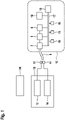
- figure 1 shows a schematic representation of a system consisting of an exhaust gas measuring device 12,13,14, an OBD measuring device 18 and an evaluation device 20, the system carrying out a diagnosis of an internal combustion engine 5 of a motor vehicle 10 and of the devices 6,7 connected to the internal combustion engine 5.
- the motor vehicle 10 is shown in a highly simplified manner by the dashed line.
- a device 6 connected to the internal combustion engine 5 is an engine 6 of the motor vehicle 10 which is driven by the internal combustion engine 5 .
- the engine 6 burns any type of fuel, in particular diesel, petrol or gas.
- the internal combustion engine 5 is connected to further devices 7 .
- the other devices 7 connected to the internal combustion engine 5 are, for example, a fuel supply device 7 and/or an air supply device 7 and/or an exhaust gas aftertreatment device 7.
- the fuel supply device 7 can have, for example, at least one pump, a fuel filter, a fuel tank with level sensors, a pressure relief valve, a rail, a rail pressure sensor and at least one injector.
- the device for air supply 7 can have, for example, an exhaust gas recirculation cooler, a control valve, an exhaust gas recirculation controller with exhaust gas recirculation valve and position sensor, an intercooler with bypass, an exhaust gas turbocharger, and a charge air controller.
- the device for exhaust gas aftertreatment 7 can have, for example, an oxidation catalytic converter, a particle filter (CSF), a soot sensor, a reducing agent tank, a reducing agent pump, a reducing agent nozzle, a reducing agent delivery pump, a reducing agent nozzle, a NO x sensor, an SCR catalytic converter and an NH3 sensor .
- CSF particle filter
- the device for exhaust gas aftertreatment 7 is connected to an exhaust pipe 8 which emits exhaust gases into the environment.
- the motor vehicle 10 also has at least one vehicle bus 17 which is connected to at least one internal control unit 15 and other sensors 19 or control devices 19 . Functions within motor vehicle 10 are monitored, analyzed and controlled by control unit 15 and additional sensors 19 or control devices 19 .
- the vehicle bus 17 is also connected to the internal combustion engine 5 and to the devices 6 , 7 connected to the internal combustion engine 5 .
- An on-board diagnosis of the internal combustion engine 5 and of the devices 6 , 7 connected to the internal combustion engine 5 can be carried out with the aid of the control unit 15 .
- can Values such as the temperature or the speed of the motor 6 can be determined.
- the measured values shown in the following table can be determined within an on-board diagnosis.
- Control unit 15 is connected to at least one interface 16 via vehicle bus 17 .
- This interface 16 can be an OBD interface to which an OBD measuring device 18 can be connected.
- the interface 18 can also be a transmission module, which can set up a wireless connection to an OBD measuring device 18 or an external computer 20 .
- the exhaust gas analyzer ( 12 , 13 , 14 ) analyzes at least one exhaust gas value of the motor vehicle 10 using a probe 11 that is inserted into the exhaust pipe 8 or placed in the vicinity of the exhaust pipe 8 .
- the first exhaust gas measuring device 12 measures at least one exhaust gas value which describes a concentration of the gaseous component of the exhaust gas.
- concentrations of the gases CO, HC; 02, NO, CO2 and NO2 are recorded.
- the first exhaust gas measuring device 12 can also determine the lambda value of the exhaust gas.
- a second exhaust gas measuring device 14 measures at least one exhaust gas value which characterizes the particles contained in the exhaust gas in addition to the gaseous components.
- This exhaust gas value can be an absorption coefficient, which is determined as part of a turbidity measurement.
- this exhaust gas value can also be characterized by the particle size and/or the number of particles in the exhaust gas.
- the first exhaust gas measuring device 12 can also determine the lambda value of the exhaust gas.
- the system for diagnosing an internal combustion engine 5 of a motor vehicle 10 and the devices 6.7 connected to the internal combustion engine 5 can include either the first exhaust gas measuring device 12 or the second exhaust gas measuring device 14 or both exhaust gas measuring devices 12,14.
- the first exhaust gas measuring device 12 and the second exhaust gas measuring device 14 are contained in a universal exhaust gas measuring device 13 , the universal exhaust gas measuring device 13 having all the functions of the first exhaust gas measuring device 12 and all the functions of the second exhaust gas measuring device 14 .
- the universal exhaust gas measuring device 13 can analyze both an exhaust gas value, which describes a concentration of the gaseous component of the exhaust gas, and an exhaust gas value, which describes a concentration of the gaseous component of the exhaust gas.
- the system has an evaluation device 20 which is in wireless or wired connection with both the exhaust gas measuring device 12 , 13 , 14 and the OBD measuring device 18 .
- the evaluation device 20 can also be integrated into the OBD measuring device or into the exhaust gas measuring device 12, 13, 14.
- figure 2 shows a flow chart which describes the method according to the invention.
- the method steps 110 to 150 are preferably carried out by the evaluation device 20 .
- a vehicle identification takes place on the basis of data which the evaluation device 20 receives from an OBD measuring device 18 .
- the OBD measuring device 18 determines data that is stored in the vehicle on a control unit 15 or on the vehicle bus 17 .
- a vehicle identification can take place, for example, on the VIN (Vehicle Identification Number) of the vehicle 10 .
- the EURO pollutant class of the vehicle 10 can also be determined as part of the vehicle identification.
- a dynamic, vehicle-specific adjustment of the threshold values can take place.
- a test cycle is determined on the basis of the vehicle identification, the test cycle comprising a plurality of predefined states (phases) of internal combustion engine 5.
- a state (phase) of a test cycle can include, for example, a speed range that should be maintained within a specified time interval.
- At least one exhaust gas value and at least one OBD measured value are received by evaluation device 20 when the test cycle is run through.
- the exhaust gas value is determined from the exhaust gas of the vehicle 10 by at least one exhaust gas measuring device 13 , 14 , 15 in method step 130 .
- the OBD measurement value is received by the OBD measurement device 18 via the interface 16, the OBD measurement value being measured by the vehicle-internal control unit 15 as part of an on-board diagnosis.
- a malfunction affecting internal combustion engine 7 and/or a device 6 connected to internal combustion engine 7 is derived from the at least one exhaust gas value and the at least one OBD measured value by evaluation device 20.
- method steps 120, 130 and 140 can be repeated one or more times.
- m method step 120 usually defines a test cycle that has a smaller number of states (phases). Phase 4 shown in the example is usually repeated.
- a defective component is identified based on the malfunction. If a clear identification of the faulty component is not possible, a priority is set according to which the faulty component can be searched for in a subsequent detailed analysis. Alternatively, a replacement suggestion is defined with a specific sequence of possible defective components.
- the evaluation device 20 receives the engine temperature and the speed of the vehicle 10 as OBD measured values.
- the evaluation device 20 also receives the concentrations of the gaseous components of HC and CO and the lambda value as exhaust gas values.
- a general malfunction in the vehicle 10 can be derived from an HC value of 20 ppm at a speed of ⁇ 1100 rpm over a period of more than 10 seconds and an engine temperature of over 80 degrees. If the CO value is also > 0.01% vol and Lambda ⁇ 2, there is a malfunction in the air supply device.
- the evaluation device 20 receives the engine temperature and the rotational speed of the vehicle 10 as OBD measured values. Furthermore, the evaluation device 20 receives the turbidity or an exhaust gas coefficient as exhaust gas values.
- An absorption coefficient greater than 0.1m -1 , a speed increase from a value of ⁇ 1100rpm to at least 2500rpm within 0.5 seconds and an engine temperature of over 80 degrees indicate a malfunction in the exhaust aftertreatment device, in particular the diesel particle filter.
- the evaluation device 20 receives the exhaust gas temperature and the speed of the vehicle 10 as the OBD measured value.
- the exhaust gas temperature can be measured by the exhaust gas measuring device.
- the evaluation device 20 receives the lambda value, the concentration of the NO in the exhaust gas and the turbidity or an exhaust gas coefficient as exhaust gas values.
- the evaluation device 20 receives the exhaust gas temperature and the speed of the vehicle 10 as OBD measured values.
- the exhaust gas temperature can be measured by the exhaust gas measuring device.
- the evaluation device 20 receives the lambda value, the concentration of the NO and the O 2 in the exhaust gas and the turbidity or the exhaust gas coefficient as exhaust gas values.
- the phase in which the measurements take place can be repeated several times in order to verify the results and rule out an error in the measurement and the resulting error derivation.
Landscapes
- Engineering & Computer Science (AREA)
- Chemical & Material Sciences (AREA)
- Combustion & Propulsion (AREA)
- Mechanical Engineering (AREA)
- General Engineering & Computer Science (AREA)
- Physics & Mathematics (AREA)
- General Physics & Mathematics (AREA)
- Chemical Kinetics & Catalysis (AREA)
- Testing Of Engines (AREA)
- Exhaust Gas After Treatment (AREA)
- Combined Controls Of Internal Combustion Engines (AREA)
Description
- Die Erfindung betrifft ein Verfahren zur Diagnose einer Brennkraftmaschine eines Kraftfahrzeuges, sowie der mit der Brennkraftmaschine verbundenen Vorrichtungen, sowie ein System zur Durchführung des Verfahrens.
- Aus der
EP 2514 954 B1 ist ein Diagnoseverfahren für eine Dieselkraftmaschine zum Bestimmen, ob die Kraftmaschine oder wenigstens eine mit der Kraftmaschine verbundene Vorrichtung durch eine oder mehrere Fehlfunktionen beeinflusst ist, die auf den Grad der Verschmutzung der durch die Kraftmaschine erzeugten Abgase negative Auswirkungen haben, bekannt. Dieses Diagnoseverfahren analysiert den Pegel des Abgases Kohlendioxid und leitet daraus eine Fehlfunktion der Kraftmaschine ab. Ein weiteres Beispiel ist dieWO 02/14828 A2 - Es ist eine Aufgabe der Erfindung ein Verfahren zur Diagnose einer Brennkraftmaschine eines Kraftfahrzeuges, sowie der mit der Brennkraftmaschine verbundenen Vorrichtungen, sowie ein System zur Durchführung des Verfahrens bereitzustellen. Herkömmliche Diagnoseverfahren basieren nur auf einer Untersuchung der Abgaswerte, wie im Stand der Technik beschrieben. Dieses Vorgehen erlaubt meist nur grobe und schlecht reproduzierbare Aussagen über vorhandenen Fehler und die Komponenten, welche defekt sind. Aus diesem Grund werden im erfindungsgemäßen Verfahren und in der erfindungsgemäßen Vorrichtung durch weitere Messkanäle zusätzliche Informationen über das Fahrzeug bestimmt, so dass verbesserte Diagnoseaussagen möglich sind. Die zusätzlichen Messwerte setzen sich aus Daten, Messwerten und Fehlerinformationen, welche über eine On-Board-Diagnose vom Fahrzeug selber bereitgestellt werden und über eine Schnittstelle durch ein OBD-Messgerät ausgelesen werden können.
- Zusätzlich werden Abgaswerte analysiert, welche sowohl Informationen über die Konzentration der gasförmigen Komponenten des Abgases geben und/oder Abgaswerte, welche die Partikel, welche neben den gasförmigen Abgasbestandteilen im Agas enthalten sind, charakterisieren.
- Des Weiteren wird ein System aus einem Abgasmessgerät, einem OBD-Messgerät und einer Auswerteeinrichtung zur Diagnose einer Brennkraftmaschine eines Kraftfahrzeuges sowie der mit der Brennkraftmaschine verbundenen Vorrichtungen, auf welchen das erfinderische Verfahren durchführbar ist, beansprucht.
- Das erfinderische Verfahren umfasst die Verfahrensschritte gemäß Anspruch 1.
- Die Verfahrensschritte werden in Abhängigkeit von mehreren vorgegebenen Zuständen der Brennkraftmaschine durchgeführt, da durch die jeweiligen vorgegebenen Zustände die Brennkraftmaschine in einen Betriebszustand versetzt wird, der eine Aktivierung gewisser Komponenten im Fahrzeug bewirkt. Entsprechen die gesammelten Messwerte (OBD-Messwerte und Abgaswerte) nicht den Erwartungen, kann ein Fehler abgeleitet werden.
- Die Fahrzeugidentifikation erfolgt über das OBD-Messgerät , da dies Fehler durch einen Anwender ausschließt und sehr komfortabel ist. Abhängig von der Fahrzeugidentifikatior werden die vorgegebenen Zustände definiert, da dies eine Einstellung von einer Testumgebung abhängig vom jeweiligen Fahrzeug ermöglicht und somit die Aussagefähigkeit der Diagnose erhöht.
- Vorteilhafte Testumgebungen lassen sich durch Zustände definieren, bei denen ein Drehzahlverlauf über ein Zeitintervallvorgegeben wird.
- Ein weiterer Vorteil ergibt sich, wenn das OBD-Messgerät Informationen über Fehler einer OBD-Analyse an die Auswerteeinrichtung übermittelt da diese Informationen bei der Detektion von Fehlerhaften Komponenten genutzt werden können. Des Weiteren lässt sich durch diese Informationen eine gezieltere und bessere Vorgabe von Zuständen einstellen.
- Vorteilhaft ist eine Ermittlung der Motortemperatur und des Lambda-Wertes durch das OBD-Messgerät als erste führende Information, da diese Messwerte eine hohe Aussagekraft über mögliche Defekte in den Komponenten des Fahrzeuges haben.
- Bevorzugte Ausführungsbeispiele der Erfindung sind in der Zeichnung dargestellt und in der nachfolgenden Beschreibung näher erläutert.
- Es zeigen:
-
Figur 1 eine schematische Darstellung eines System aus einem Abgasmessgerät, einem OBD-Messgerät und einer Auswerteeinrichtung mit einem Fahrzeug, -
Figur 2 ein Flussablaufdiagramm des erfinderischen Verfahrens gemäß einer ersten Ausführungsform der vorliegenden Erfindung und -
Figur 1 zeigt eine schematische Darstellung eines Systems aus einem Abgasmessgerät 12,13,14, einem OBD-Messgerätes 18 und einer Auswerteeinrichtung 20, wobei das System eine Diagnose einer Brennkraftmaschine 5 eines Kraftfahrzeuges 10, sowie der mit der Brennkraftmaschine 5 verbundenen Vorrichtungen 6,7 durchführt. Das Kraftfahrzeug 10 ist durch die gestrichelte Linie stark vereinfacht dargestellt. - Eine mit der Brennkraftmaschine 5 verbundene Vorrichtung 6 ist ein Motor 6 des Kraftfahrzeuges 10, welcher durch die Brennkraftmaschine 5 angetrieben wird. Der Motor 6 verbrennt eine beliebigen Kraftstoffsorte, insbesondere Diesel, Benzin oder Gas.
- Die Brennkraftmaschine 5 ist mit weiteren Vorrichtungen 7 verbunden. Die weiteren mit der Brennkraftmaschine 5 verbundenen Vorrichtungen 7 sind beispielsweise eine Vorrichtung zur Kraftstoffversorgung 7 und /oder eine Vorrichtung zur Luftversorgung 7 und/oder eine Vorrichtung zur Abgasnachbehandlung 7.
- Die Vorrichtung zur Kraftstoffversorgung 7 kann beispielsweise mindestens eine Pumpe, einen Kraftstofffilter, einen Kraftstofftank mit Füllstandssensoren, ein Druckbegrenzungsventil, eine Rail, einen Raildrucksensor und mindestens einen Injektor aufweisen.
- Die Vorrichtung zur Luftversorgung 7 kann beispielsweise einen Abgasrückführkühler, einen Regelklappe, einen Abgasrückführsteller mit Abgasrückführventil und Positionsmesser, einen Ladeluftkühler mit Bypass,, einen Abgasturbolader, und einen Ladeluftsteller aufweisen.
- Die Vorrichtung zur Abgasnachbehandlung 7 kann beispielsweise einen Oxidationskatalysator, einen Partikelfilter (CSF), einen Russsensor, einen Reduktionsmitteltank, eine Reduktionsmittelpumpe, eine Reduktionsmitteldüse, eine Reduktionsmittelförderpump, eine Reduktionsmitteldüse, einen Nox-Sensor, einen SCR-Katalysator und einen NH3-Sensor aufweisen.
- Die Vorrichtung zur Abgasnachbehandlung 7 ist mit einem Abgasrohr 8, welches Abgase in die Umgebung abgibt, verbunden.
- Das Kraftfahrzeug 10 weist des Weiteren mindestens einen Fahrzeugbus 17 auf, welcher mit mindestens einem internen Steuergerät 15 und weiteren Sensoren 19 bzw. Steuereinrichtungen 19 verbunden ist. Durch das Steuergerät 15 und die weiteren Sensoren 19 bzw. Steuereinrichtungen 19 werden Funktionen innerhalb des Kraftfahrzeuges 10 kontrolliert, analysiert und angesteuert.
- Der Fahrzeugbus 17 ist auch mit der Brennkraftmaschine 5 und mit den mit der Brennkraftmaschine 5 verbundenen Vorrichtungen 6,7 verbunden. Mit Hilfe des Steuergerätes 15 kann eine On-Board-Diagnose der Brennkraftmaschine 5, sowie der mit der Brennkraftmaschine 5 verbundenen Vorrichtungen 6,7 durchführt werden. Dabei können Werte wie beispielsweise die Temperatur oder die Drehzahl des Motors 6 bestimmt werden. Des Weiteren können beispielsweise die in der folgenden Tabelle dargestellten Messwerte innerhalb einer On-Board-Diagnose bestimmt werden. Das Steuergerät 15 ist über den Fahrzeugbus 17 mit mindestens einer Schnittstelle 16 verbunden. Diese Schnittstelle 16 kann eine OBD-Schnittstelle sein, an welche ein OBD-Messgerät 18 angeschlossen werden kann. Alternativ kann die Schnittstelle 18 auch ein Sendemodul sein, welches eine kabellose Verbindung zu einem OBD-Messgerät 18 oder einem externen Computer 20 aufbauen kann.
- Das Abgasmessgerät (12,13,14) analysiert mindestens eines Abgaswertes des Kraftfahrzeuges 10 mit Hilfe einer Sonde 11, die in das Abgasrohr 8 eingeführt wird oder in der Nähe des Abgasrohres 8 platziert wird.
- Das erste Abgasmessgerät 12 misst mindestens einen Abgaswert, welche eine Konzentration der gasförmigen Komponente des Abgases beschreibt. Hierbei können die Konzentrationen der Gase CO, HC; 02, NO, CO2 und NO2 erfasst werden. Des Weiteren kann das erste Abgasmessgerät 12 auch den Lambdawert des Abgases bestimmen.
- Ein zweites Abgasmessgerät 14 misst mindestens einen Abgaswert, welcher die Partikel, die neben den gasförmigen Komponenten im Abgas enthalten sind, charakterisiert. Dieser Abgaswert kann ein Absorptionskoeffizient sein, welcher im Rahmen einer Trübungsmessung bestimmt wird. Alternativ kann dieser Abgaswert aber auch durch die Partikelgröße und/oder die Partikelanzahl im Abgas charakterisiert werden. Des Weiteren kann das erste Abgasmessgerät 12 auch den Lambdawert des Abgases bestimmen.
- Das System zur Diagnose einer Brennkraftmaschine 5 eines Kraftfahrzeuges 10, sowie der mit der Brennkraftmaschine 5 verbundenen Vorrichtungen 6,7 kann entweder das erste Abgasmessgerät 12 oder das zweite Abgasmessgerät 14 oder beide Abgasmessgeräte 12,14 umfassen.
- In einer alternativen Ausführungsform, sind das erste Abgasmessgerät 12 und das zweite Abgasmessgerät 14 in einem Universal-Abgasmessgerät 13 enthalten, wobei das Universal-Abgasmessgerät 13 alle Funktionen des ersten Abgasmessgerätes 12 und alle Funktionen des zweiten Abgasmessgerätes 14 aufweist. Das Universal-Abgasmessgerät 13 kann sowohl einen Abgaswert, welche eine Konzentration der gasförmigen Komponente des Abgases beschreibt, als auch einen Abgaswert, welcher eine Konzentration der gasförmigen Komponente des Abgases beschreibt, analysieren.
- Des Weiteren weist das System eine Auswerteeinrichtung 20 auf, welche sowohl mit dem Abgasmessgerät 12, 13, 14, als auch mit dem OBD-Messgerät 18 in kabelloser oder kabelgebundener Verbindung steht. Die Auswerteeinrichtung 20 kann auch in das OBD-Messgerät oder in das Abgasmessgerät 12, 13, 14 integriert sein.
-
Figur 2 zeigt ein Flussablaufdiagramm, welches das erfindungsgemäße Verfahren beschreibt. Die Verfahrensschritte 110 bis 150 werden bevorzugt durch die Auswerteeinrichtung 20 durchgeführt. - Im Verfahrensschritt 110 findet eine Fahrzeugidentifikation aufgrund von Daten, die die Auswerteeinrichtung 20 von einem OBD-Messgerät 18 empfängt, statt. Das OBD-Messgerät 18 ermittelt im Verfahrensschritt 110 Daten, die im Fahrzeug auf einem Steuergerät 15 oder dem Fahrzeugbus 17 abgelegt sind. Eine Fahrzeugidentifikation kann beispielsweise auf der VIN (Vehikel Identification Number) des Fahrzeuges 10 erfolgen. Des Weiteren kann im Rahmen der Fahrzeugidentifikation auch die EURO-Schadstoffklasse der Fahrzeuges 10 bestimmt werden. Abhängig von der Fahrzeugidentifikation kann eine dynamisch, fahrzeugspezifische Anpassung der Schwellwerte erfolgen.
- Im Verfahrensschritt 120 findet aufgrund der Fahrzeugidentifikation eine Festlegung eines Prüfzyklus statt, wobei der Prüfzyklus mehrere vorgegebene Zustände (Phasen) der Brennkraftmaschine 5 umfasst. Ein Zustand (Phase) eines Prüfzyklus kann beispielsweise einen Drehzahlbereich, der innerhalb eines vorgegebenen Zeitintervalls eingehalten werde sollte, umfassen.
- Beispiel eines Prüfzyklus:
- Phase 1: Drehzahl < 1100rpm ; Dauer t=30s
- Phase 2: Drehzahl 3100rpm ; Dauer t=30s
- Phase 3: Beschleunigung auf Abregeldrehzahl ; Dauer t=10s
- Phase 4: Drehzahl < 1100rpm , Dauer t=30s
- Phase 5: Motor aus ; Zündung an; Dauer 30 s
- Im Verfahrensschritt 130 werden beim Durchlaufen des Prüfzyklus mindestens ein Abgaswert und mindestens ein OBD-Messwert durch die Auswerteeinrichtung 20 empfangen. Der Abgaswert wird durch mindestens ein Abgasmessgerät 13,14,15 im Verfahrensschritt 130 aus dem Abgas des Fahrzeuges 10 bestimmt. Der OBD-Messwert wird durch das OBD-Messgerät 18 über die Schnittstelle 16 empfangen, wobei der OBD-Messwert im Rahmen einer On-Bord-Diagnose durch das fahrzeuginterne Steuergerät 15 gemessen wurde.
- Im Verfahrensschritt 140 wird aus dem mindestens einem Abgaswerte und dem mindestens einen OBD-Messwert durch die Auswerteeinrichtung 20 einer Fehlfunktion, die die Brennkraftmaschine 7 und/oder eine mit der Brennkraftmaschine 7 verbundene Vorrichtung 6 beeinflusst, abgeleitet.
- Um die Fehlfunktion mit einer höheren Wahrscheinlichkeit zu verifizieren, können die Verfahrensschritte 120,130 und 140 einmal oder mehrfach wiederholt werden. Dabei wird m Verfahrensschritt 120 meist ein Prüfzyklus festgelegt, der eine geringere Anzahl von Zuständen (Phasen) aufweist. Meist wird die im Beispiel aufgeführte Phase 4 wiederholt.
- Im Verfahrensschritt 150 wird anhand der Fehlfunktion eine Defekte Komponente identifiziert. Falls eine eindeutige Identifikation der fehlerhaften Komponente nicht möglich ist, wird eine Priorität festgelegt nach welcher im Rahmen einer nachfolgenden Detailanalyse nach der fehlerhaften Komponente gesucht werden kann. Alternativ wird ein Tauschvorschlag mit einer bestimmten Reihenfolge von möglichen defekten Komponenten definiert.
- Im Folgenden werden mögliche Fehlfunktionen, welche sich aus dem mindestens einen Abgaswert und dem mindestens ein OBD-Messwert ableiten lassen, beschrieben.
- Fehlfunktion in Vorrichtung zur Luftversorgung:
Im Verfahrensschritt 130 empfängt die Auswerteeinrichtung 20 als OBD-Messwerte die Motortemperatur und die Drehzahl des Fahrzeuges 10. Des Weiteren empfängt die Auswerteeinrichtung 20 als Abgaswerte die Konzentrationen der gasförmigen Komponenten von HC und CO sowie den Lambda-Wert. - Aus einem HC-Wert von 20 ppm bei einer Drehzahl von <1100rpm über eine Dauer von mehr als 10 Sekunden und einer Motortemperatur von über 80 Grad lässt sich eine allgemeine Fehlfunktion im Fahrzeug 10 ableiten. Ist zusätzlich der CO-Wert > 0,01 %vol und Lambda <2 liegt eine Fehlfunktion in der Vorrichtung zur Luftversorgung vor.
- Fehlfunktion in Vorrichtung zur Abgasnachbehandlung (DPF):
- Im Verfahrensschritt 130 empfängt die Auswerteeinrichtung 20 als OBD-Messwerte die Motortemperatur und die Drehzahl des Fahrzeuges 10. Des Weiteren empfängt die Auswerteeinrichtung 20 als Abgaswerte die Trübung bzw. einen Abgaskoeffizienten. Aus einem Absorptionskoeffizienten der größer als 0,1m-1 ist, einem Drehzahlanstieg von einem Wert <1100rpm auf mindestens 2500rpm innerhalb von 0,5 Sekunden und einer Motortemperatur von über 80 Grad lässt sich eine Fehlfunktion in der Vorrichtung zur Abgasnachbehandlung, insbesondere des Dieselpartikelfilters, ableiten.
- Im Verfahrensschritt 130 empfängt die Auswerteeinrichtung 20 als OBD-Messwert die Abgastemperatur und die Drehzahl des Fahrzeuges 10. Alternativ kann die Abgastemperatur durch das Abgasmessgerät gemessen werden. Des Weiteren empfängt die Auswerteeinrichtung 20 als Abgaswerte den Lambda-Wert, die Konzentration des NO im Abgas und die Trübung bzw. einen Abgaskoeffizienten.
- Falls im Rahmen der Fahrzeugidentifikation im Verfahrensschritt 110 ein Fahrzeug 10 ohne SCR (Selective catalytic reduction) identifiziert wurde, kann folgender Fehler vorliegen: Ist in der Phase 4 ein Anstieg der Konzentration von NO bei einem Lambda-Wert >2 und einem Absorptionskoeffizienten von >= 0,1m-1 ohne einen signifikanten Temperaturanstieg erkennbar, so lässt sich daraus ein Defekt des Abgastemperatursensors ableiten.
- Im Verfahrensschritt 130 empfängt die Auswerteeinrichtung 20 als OBD-Messwerte die Abgastemperatur und die Drehzahl des Fahrzeuges 10. Alternativ kann die Abgastemperatur durch das Abgasmessgerät gemessen werden. Des Weiteren empfängt die Auswerteeinrichtung 20 als Abgaswerte den Lambda-Wert, die Konzentration des NO und des O2 im Abgas und die Trübung bzw. den Abgaskoeffizienten..
- Falls im Rahmen der Fahrzeugidentifikation im Verfahrensschritt 110 ein Fahrzeug 10 ohne SCR (Selective catalytic reduction) identifiziert wurde, kann folgender Fehler vorliegen: Zeigt sich in der EGR-Rate eine signifikante Veränderung aber keine entsprechende signifikante Änderung in den Abgaskonzentrationen, z.b. NO im entsprechenden Drehzahlbereich und Abgastemperaturbereich, so ist das ein Zeichen eines festsitzenden Abgasregelventils.
- In den genannten Beispielen kann die Phase in der die Messungen stattfinden mehrmals wiederholt werden, um die Ergebnisse zu verifizieren und einen Fehler in der Messung und der daraus folgenden Fehlerableitung auszuschließen.
Claims (9)
- Verfahren zur Diagnose einer Brennkraftmaschine (7) eines Kraftfahrzeuges (10) sowie der mit der Brennkraftmaschine (10) verbundenen Vorrichtungen (6), mit den Verfahrensschritten:- Durchführen einer Fahrzeugidentifikation aufgrund von Daten, die die Auswerteeinrichtung (20) von einem OBD-Messgerät (18) empfängt, wobei die Daten im Fahrzeug auf einem Steuergerät (15) oder dem Fahrzeugbus (17) abgelegt sind,- Festlegen eines Prüfzyklus aufgrund der Fahrzeugidentifikation, wobei der Prüfzyklus mehrere vorgegebene Zustände (Phasen) der Brennkraftmaschine (5) umfasst,- Analysieren mindestens eines Abgaswertes durch ein Abgasmessgerät (13,14,15),- Bestimmen mindestens eines OBD-Messwertes, welcher im Rahmen einer On-Bord-Diagnose durch ein fahrzeuginternes Steuergerät (15) analysiert wird, durch das OBD-Messgerät (18),- Übermitteln des mindestens einen Abgaswertes und des mindestens einen OBD-Messwertes an eine Auswerteeinrichtung (20),- Ableiten einer Fehlfunktion, die die Brennkraftmaschine (7) und/oder eine mit der Brennkraftmaschine (7) verbundene Vorrichtung (6) beeinflusst, aus dem mindestens einem Abgaswerte und dem mindestens OBD- Messwert durch die Auswerteeinrichtung (20).
- Verfahren nach Anspruch 1, wobei der Abgaswert eine Konzentration einer gasförmigen Komponente des Abgases ist.
- Verfahren nach Anspruch 1 oder 2, wobei der Abgaswert durch die Partikelgröße und/oder Partikelanzahl im Abgas charakterisiert wird.
- Verfahren nach Anspruch 1 oder 2, wobei der Abgaswert ein Absorptionskoeffizient ist, welcher im Rahmen einer Trübungsmessung bestimmt wird.
- Verfahren nach einem der vorherigen Ansprüche, wobei die Verfahrensschritte in Abhängigkeit von mehreren vorgegebenen Zuständen der Brennkraftmaschine (7) durchgeführt werden.
- Verfahren nach Anspruch 5, wobei der vorgegebene Zustand durch Vorgabe eines Drehzahlverlaufs über ein Zeitintervall definiert wird.
- Verfahren nach einem der vorherigen Ansprüche, wobei das OBD-Messgerät (18) Informationen über Fehler einer OBD-Analyse an die Auswerteeinrichtung (20) übermittelt.
- Verfahren nach einem der vorherigen Ansprüche, wobei das OBD-Messgerät (20) als erste führende Information immer die Motortemperatur und den Lambda-Wert ermittelt.
- System aus einem Abgasmessgerät (12,13,14), einem OBD-Messgerät (18) und einer Auswerteeinrichtung (20) zur Diagnose einer Brennkraftmaschine (7) eines Kraftfahrzeuges (10) sowie der mit der Brennkraftmaschine (7) verbundenen Vorrichtungen (6), dadurch gekennzeichnet, dass durch das System ein Verfahren nach einem der Ansprüche 1 bis 8 durchgeführt wird.
Applications Claiming Priority (3)
| Application Number | Priority Date | Filing Date | Title |
|---|---|---|---|
| DE102017208858 | 2017-05-24 | ||
| DE102017211220.4A DE102017211220A1 (de) | 2017-05-24 | 2017-06-30 | Verfahren zur Diagnose einer Brennkraftmaschine eines Kraftfahrzeuges, sowie der mit der Brennkraftmaschine verbundenen Vorrichtungen, sowie ein System zur Durchführung des Verfahrens |
| PCT/EP2018/063332 WO2018215430A1 (de) | 2017-05-24 | 2018-05-22 | Verfahren zur diagnose einer brennkraftmaschine eines kraftfahrzeuges, sowie der mit der brennkraftmaschine verbundenen vorrichtungen, sowie ein system zur durchführung des verfahrens |
Publications (2)
| Publication Number | Publication Date |
|---|---|
| EP3631186A1 EP3631186A1 (de) | 2020-04-08 |
| EP3631186B1 true EP3631186B1 (de) | 2022-08-03 |
Family
ID=64109545
Family Applications (1)
| Application Number | Title | Priority Date | Filing Date |
|---|---|---|---|
| EP18726964.2A Active EP3631186B1 (de) | 2017-05-24 | 2018-05-22 | Verfahren zur diagnose einer brennkraftmaschine eines kraftfahrzeuges, sowie der mit der brennkraftmaschine verbundenen vorrichtungen, sowie ein system zur durchführung des verfahrens |
Country Status (4)
| Country | Link |
|---|---|
| EP (1) | EP3631186B1 (de) |
| CN (1) | CN110621865B (de) |
| DE (1) | DE102017211220A1 (de) |
| WO (1) | WO2018215430A1 (de) |
Families Citing this family (13)
| Publication number | Priority date | Publication date | Assignee | Title |
|---|---|---|---|---|
| US11828210B2 (en) | 2020-08-20 | 2023-11-28 | Denso International America, Inc. | Diagnostic systems and methods of vehicles using olfaction |
| US11813926B2 (en) | 2020-08-20 | 2023-11-14 | Denso International America, Inc. | Binding agent and olfaction sensor |
| US11881093B2 (en) | 2020-08-20 | 2024-01-23 | Denso International America, Inc. | Systems and methods for identifying smoking in vehicles |
| US12251991B2 (en) | 2020-08-20 | 2025-03-18 | Denso International America, Inc. | Humidity control for olfaction sensors |
| US11760169B2 (en) | 2020-08-20 | 2023-09-19 | Denso International America, Inc. | Particulate control systems and methods for olfaction sensors |
| US11636870B2 (en) | 2020-08-20 | 2023-04-25 | Denso International America, Inc. | Smoking cessation systems and methods |
| US11932080B2 (en) | 2020-08-20 | 2024-03-19 | Denso International America, Inc. | Diagnostic and recirculation control systems and methods |
| US12017506B2 (en) | 2020-08-20 | 2024-06-25 | Denso International America, Inc. | Passenger cabin air control systems and methods |
| US12269315B2 (en) | 2020-08-20 | 2025-04-08 | Denso International America, Inc. | Systems and methods for measuring and managing odor brought into rental vehicles |
| US11760170B2 (en) | 2020-08-20 | 2023-09-19 | Denso International America, Inc. | Olfaction sensor preservation systems and methods |
| US12377711B2 (en) | 2020-08-20 | 2025-08-05 | Denso International America, Inc. | Vehicle feature control systems and methods based on smoking |
| CN115855512A (zh) * | 2022-11-28 | 2023-03-28 | 广西玉柴机器股份有限公司 | 用于演示dpf效率低故障的劣化件obd制作方法 |
| AT527142B1 (de) * | 2023-11-06 | 2024-11-15 | Avl List Gmbh | Verfahren und Testsystem zum Verifizieren eines On-Board-Monitoringsystems |
Family Cites Families (7)
| Publication number | Priority date | Publication date | Assignee | Title |
|---|---|---|---|---|
| DE19946628A1 (de) * | 1999-09-29 | 2001-04-05 | Volkswagen Ag | Verfahren zur Diagnose eines Schädigungszustandes eines in einem Abgaskanal einer Verbrennungskraftmaschine angeordneten NOx-Speicherkatalysators |
| DE10039965A1 (de) * | 2000-08-16 | 2002-02-28 | Siemens Ag | Verfahren und Anordnung zur Abgasuntersuchung an Kraftfahrzeugen mit bordeigenem Motorsteuerungs- und Diagnosesystem |
| DE10124235B4 (de) * | 2001-05-18 | 2004-08-12 | Esytec Energie- Und Systemtechnik Gmbh | Verfahren und Vorrichtung zur umfassenden Charakterisierung und Kontrolle des Abgases und der Regelung von Motoren, speziell von Verbrennungsmotoren, und von Komponenten der Abgasnachbehandlung |
| FR2906565B1 (fr) * | 2006-10-02 | 2008-11-14 | Renault Sas | Procede de diagnostic et dispositif de diagnostic d'un systeme d'elimination de particules de gaz d'echappement. |
| FR2919671B1 (fr) | 2007-08-03 | 2009-10-30 | Sphere Tech Europ Sarl | Procede de diagnostic d'un moteur a combustion interne par analyse des gaz d'echappement et dispositif de mise en oeuvre. |
| DE102009027378A1 (de) * | 2009-07-01 | 2011-01-05 | Robert Bosch Gmbh | Verfahren und Diagnosevorrichtung zur Diagnose einer beheizbaren Abgassonde einer Brennkraftmaschine |
| DE102014201000A1 (de) * | 2014-01-21 | 2015-07-23 | Volkswagen Aktiengesellschaft | Verfahren zur Diagnose eines Abgaskatalysators sowie Kraftfahrzeug |
-
2017
- 2017-06-30 DE DE102017211220.4A patent/DE102017211220A1/de not_active Withdrawn
-
2018
- 2018-05-22 CN CN201880034186.9A patent/CN110621865B/zh active Active
- 2018-05-22 EP EP18726964.2A patent/EP3631186B1/de active Active
- 2018-05-22 WO PCT/EP2018/063332 patent/WO2018215430A1/de not_active Ceased
Also Published As
| Publication number | Publication date |
|---|---|
| WO2018215430A1 (de) | 2018-11-29 |
| CN110621865B (zh) | 2022-05-24 |
| DE102017211220A1 (de) | 2018-11-29 |
| EP3631186A1 (de) | 2020-04-08 |
| CN110621865A (zh) | 2019-12-27 |
| BR112019024315A2 (pt) | 2020-06-16 |
Similar Documents
| Publication | Publication Date | Title |
|---|---|---|
| EP3631186B1 (de) | Verfahren zur diagnose einer brennkraftmaschine eines kraftfahrzeuges, sowie der mit der brennkraftmaschine verbundenen vorrichtungen, sowie ein system zur durchführung des verfahrens | |
| EP3667049B1 (de) | Verfahren zum erkennen eines manipulierten betriebs einer komponente eines fahrzeugs | |
| DE102018117271A1 (de) | Modellbasierte Überwachung für eine selektive katalytische Reduktionsvorrichtung in einer Nachbehandlungsanordnung | |
| DE102013110786B4 (de) | Verfahren zur Diagnose eines Abgasrückführungssystems | |
| EP3540403A1 (de) | Verfahren zur durchführung eines prüflaufs eines prüflings | |
| EP0796390B1 (de) | Verfahren und vorrichtung zur überwachung der funktionsweise eines katalysators | |
| DE102007063940B4 (de) | Verfahren zur Diagnose eines eine Abgasbehandlungsvorrichtung enthaltenden Abgasbereichs einer Brennkraftmaschine und Vorrichtung zur Durchführung des Verfahrens | |
| DE102009046232A1 (de) | Verfahren zur Diagnose eines NOx-Messwertaufnehmers | |
| DE102019006115A1 (de) | Verfahren zur diagnose eines katalysatorabbaus und system zur diagnose eines katalysatorabbaus | |
| EP3222833B1 (de) | Verfahren zur überprüfung der nox-emissionen eines fahrzeugs | |
| DE102010028852A1 (de) | Verfahren und Vorrichtung zur Diagnose eines Abgasreinigungssystems für eine Brennkraftmaschine | |
| DE102014206252B4 (de) | Verfahren und Einrichtung zum Diagnostizieren der Funktionsfähigkeit eines Dieselpartikelfilters | |
| DE102017205322A1 (de) | Verfahren zum Erkennen einer Schädigung eines SCR-Katalysators | |
| DE102014202035A1 (de) | Verfahren und Vorrichtung zur Überwachung eines Stickoxid-Speicher-Katalysators | |
| DE102012203196B4 (de) | System zur Diagnose für Kohlenwasserstoffumwandlung | |
| DE19753006C2 (de) | Verfahren zur Beurteilung von Abgasgrenzwertverletzungen und zur Beurteilung der Güte abgasrelevanter Bauteile bei niedrig emittierenden Kraftfahrzeugen während der Fahrt | |
| AT527142B1 (de) | Verfahren und Testsystem zum Verifizieren eines On-Board-Monitoringsystems | |
| DE102014209972A1 (de) | Verfahren und Vorrichtung zum Bewerten des Alterungszustandeseines NOx-Speicherkatalysators | |
| DE102005062122B4 (de) | Verfahren und Steuergerät zur Diagnose eines Katalysatorsystems eines Verbrennungsmotors | |
| DE102013226565A1 (de) | Verfahren zur Überwachung eines in einem Abgaskanal einer Brennkraftmaschine angeordneten Bauteils, Vorrichtung zur Durchführung des Verfahrens, Computer-Programm und Computer-Programmprodukt | |
| AT525781B1 (de) | Verfahren zur überwachung von abgaswerten | |
| DE102019122663A1 (de) | Verfahren zur Überwachung eines SCR-Katalysators | |
| DE102021202712B3 (de) | Verfahren und Vorrichtung zur Manipulationskennung an einer technischen Einrichtung in einem Kraftfahrzeug mithilfe Methoden künstlicher Intelligenz | |
| DE102004053428B4 (de) | Vorrichtung zur Überprüfung der in ein Kraftfahrzeug mit einer Brennkraftmaschine eingebauten Abgasanlage | |
| DE102007037569A1 (de) | Verfahren und Vorrichtung zum Prüfen eines Abgasnachbehandlungssystems |
Legal Events
| Date | Code | Title | Description |
|---|---|---|---|
| STAA | Information on the status of an ep patent application or granted ep patent |
Free format text: STATUS: UNKNOWN |
|
| STAA | Information on the status of an ep patent application or granted ep patent |
Free format text: STATUS: THE INTERNATIONAL PUBLICATION HAS BEEN MADE |
|
| PUAI | Public reference made under article 153(3) epc to a published international application that has entered the european phase |
Free format text: ORIGINAL CODE: 0009012 |
|
| STAA | Information on the status of an ep patent application or granted ep patent |
Free format text: STATUS: REQUEST FOR EXAMINATION WAS MADE |
|
| 17P | Request for examination filed |
Effective date: 20200102 |
|
| AK | Designated contracting states |
Kind code of ref document: A1 Designated state(s): AL AT BE BG CH CY CZ DE DK EE ES FI FR GB GR HR HU IE IS IT LI LT LU LV MC MK MT NL NO PL PT RO RS SE SI SK SM TR |
|
| RAP1 | Party data changed (applicant data changed or rights of an application transferred) |
Owner name: ROBERT BOSCH GMBH |
|
| GRAP | Despatch of communication of intention to grant a patent |
Free format text: ORIGINAL CODE: EPIDOSNIGR1 |
|
| STAA | Information on the status of an ep patent application or granted ep patent |
Free format text: STATUS: GRANT OF PATENT IS INTENDED |
|
| INTG | Intention to grant announced |
Effective date: 20220301 |
|
| GRAS | Grant fee paid |
Free format text: ORIGINAL CODE: EPIDOSNIGR3 |
|
| GRAA | (expected) grant |
Free format text: ORIGINAL CODE: 0009210 |
|
| STAA | Information on the status of an ep patent application or granted ep patent |
Free format text: STATUS: THE PATENT HAS BEEN GRANTED |
|
| AK | Designated contracting states |
Kind code of ref document: B1 Designated state(s): AL AT BE BG CH CY CZ DE DK EE ES FI FR GB GR HR HU IE IS IT LI LT LU LV MC MK MT NL NO PL PT RO RS SE SI SK SM TR |
|
| REG | Reference to a national code |
Ref country code: AT Ref legal event code: REF Ref document number: 1508921 Country of ref document: AT Kind code of ref document: T Effective date: 20220815 Ref country code: CH Ref legal event code: EP |
|
| REG | Reference to a national code |
Ref country code: DE Ref legal event code: R096 Ref document number: 502018010302 Country of ref document: DE |
|
| REG | Reference to a national code |
Ref country code: IE Ref legal event code: FG4D Free format text: LANGUAGE OF EP DOCUMENT: GERMAN |
|
| REG | Reference to a national code |
Ref country code: LT Ref legal event code: MG9D |
|
| REG | Reference to a national code |
Ref country code: NL Ref legal event code: MP Effective date: 20220803 |
|
| PG25 | Lapsed in a contracting state [announced via postgrant information from national office to epo] |
Ref country code: SE Free format text: LAPSE BECAUSE OF FAILURE TO SUBMIT A TRANSLATION OF THE DESCRIPTION OR TO PAY THE FEE WITHIN THE PRESCRIBED TIME-LIMIT Effective date: 20220803 Ref country code: RS Free format text: LAPSE BECAUSE OF FAILURE TO SUBMIT A TRANSLATION OF THE DESCRIPTION OR TO PAY THE FEE WITHIN THE PRESCRIBED TIME-LIMIT Effective date: 20220803 Ref country code: PT Free format text: LAPSE BECAUSE OF FAILURE TO SUBMIT A TRANSLATION OF THE DESCRIPTION OR TO PAY THE FEE WITHIN THE PRESCRIBED TIME-LIMIT Effective date: 20221205 Ref country code: NO Free format text: LAPSE BECAUSE OF FAILURE TO SUBMIT A TRANSLATION OF THE DESCRIPTION OR TO PAY THE FEE WITHIN THE PRESCRIBED TIME-LIMIT Effective date: 20221103 Ref country code: NL Free format text: LAPSE BECAUSE OF FAILURE TO SUBMIT A TRANSLATION OF THE DESCRIPTION OR TO PAY THE FEE WITHIN THE PRESCRIBED TIME-LIMIT Effective date: 20220803 Ref country code: LV Free format text: LAPSE BECAUSE OF FAILURE TO SUBMIT A TRANSLATION OF THE DESCRIPTION OR TO PAY THE FEE WITHIN THE PRESCRIBED TIME-LIMIT Effective date: 20220803 Ref country code: LT Free format text: LAPSE BECAUSE OF FAILURE TO SUBMIT A TRANSLATION OF THE DESCRIPTION OR TO PAY THE FEE WITHIN THE PRESCRIBED TIME-LIMIT Effective date: 20220803 Ref country code: FI Free format text: LAPSE BECAUSE OF FAILURE TO SUBMIT A TRANSLATION OF THE DESCRIPTION OR TO PAY THE FEE WITHIN THE PRESCRIBED TIME-LIMIT Effective date: 20220803 Ref country code: ES Free format text: LAPSE BECAUSE OF FAILURE TO SUBMIT A TRANSLATION OF THE DESCRIPTION OR TO PAY THE FEE WITHIN THE PRESCRIBED TIME-LIMIT Effective date: 20220803 |
|
| PG25 | Lapsed in a contracting state [announced via postgrant information from national office to epo] |
Ref country code: PL Free format text: LAPSE BECAUSE OF FAILURE TO SUBMIT A TRANSLATION OF THE DESCRIPTION OR TO PAY THE FEE WITHIN THE PRESCRIBED TIME-LIMIT Effective date: 20220803 Ref country code: IS Free format text: LAPSE BECAUSE OF FAILURE TO SUBMIT A TRANSLATION OF THE DESCRIPTION OR TO PAY THE FEE WITHIN THE PRESCRIBED TIME-LIMIT Effective date: 20221203 Ref country code: HR Free format text: LAPSE BECAUSE OF FAILURE TO SUBMIT A TRANSLATION OF THE DESCRIPTION OR TO PAY THE FEE WITHIN THE PRESCRIBED TIME-LIMIT Effective date: 20220803 Ref country code: GR Free format text: LAPSE BECAUSE OF FAILURE TO SUBMIT A TRANSLATION OF THE DESCRIPTION OR TO PAY THE FEE WITHIN THE PRESCRIBED TIME-LIMIT Effective date: 20221104 |
|
| PG25 | Lapsed in a contracting state [announced via postgrant information from national office to epo] |
Ref country code: SM Free format text: LAPSE BECAUSE OF FAILURE TO SUBMIT A TRANSLATION OF THE DESCRIPTION OR TO PAY THE FEE WITHIN THE PRESCRIBED TIME-LIMIT Effective date: 20220803 Ref country code: RO Free format text: LAPSE BECAUSE OF FAILURE TO SUBMIT A TRANSLATION OF THE DESCRIPTION OR TO PAY THE FEE WITHIN THE PRESCRIBED TIME-LIMIT Effective date: 20220803 Ref country code: DK Free format text: LAPSE BECAUSE OF FAILURE TO SUBMIT A TRANSLATION OF THE DESCRIPTION OR TO PAY THE FEE WITHIN THE PRESCRIBED TIME-LIMIT Effective date: 20220803 Ref country code: CZ Free format text: LAPSE BECAUSE OF FAILURE TO SUBMIT A TRANSLATION OF THE DESCRIPTION OR TO PAY THE FEE WITHIN THE PRESCRIBED TIME-LIMIT Effective date: 20220803 |
|
| REG | Reference to a national code |
Ref country code: DE Ref legal event code: R097 Ref document number: 502018010302 Country of ref document: DE |
|
| PG25 | Lapsed in a contracting state [announced via postgrant information from national office to epo] |
Ref country code: SK Free format text: LAPSE BECAUSE OF FAILURE TO SUBMIT A TRANSLATION OF THE DESCRIPTION OR TO PAY THE FEE WITHIN THE PRESCRIBED TIME-LIMIT Effective date: 20220803 Ref country code: EE Free format text: LAPSE BECAUSE OF FAILURE TO SUBMIT A TRANSLATION OF THE DESCRIPTION OR TO PAY THE FEE WITHIN THE PRESCRIBED TIME-LIMIT Effective date: 20220803 |
|
| PLBE | No opposition filed within time limit |
Free format text: ORIGINAL CODE: 0009261 |
|
| STAA | Information on the status of an ep patent application or granted ep patent |
Free format text: STATUS: NO OPPOSITION FILED WITHIN TIME LIMIT |
|
| PG25 | Lapsed in a contracting state [announced via postgrant information from national office to epo] |
Ref country code: AL Free format text: LAPSE BECAUSE OF FAILURE TO SUBMIT A TRANSLATION OF THE DESCRIPTION OR TO PAY THE FEE WITHIN THE PRESCRIBED TIME-LIMIT Effective date: 20220803 |
|
| 26N | No opposition filed |
Effective date: 20230504 |
|
| PG25 | Lapsed in a contracting state [announced via postgrant information from national office to epo] |
Ref country code: SI Free format text: LAPSE BECAUSE OF FAILURE TO SUBMIT A TRANSLATION OF THE DESCRIPTION OR TO PAY THE FEE WITHIN THE PRESCRIBED TIME-LIMIT Effective date: 20220803 |
|
| REG | Reference to a national code |
Ref country code: CH Ref legal event code: PL |
|
| PG25 | Lapsed in a contracting state [announced via postgrant information from national office to epo] |
Ref country code: MC Free format text: LAPSE BECAUSE OF FAILURE TO SUBMIT A TRANSLATION OF THE DESCRIPTION OR TO PAY THE FEE WITHIN THE PRESCRIBED TIME-LIMIT Effective date: 20220803 |
|
| REG | Reference to a national code |
Ref country code: BE Ref legal event code: MM Effective date: 20230531 |
|
| PG25 | Lapsed in a contracting state [announced via postgrant information from national office to epo] |
Ref country code: MC Free format text: LAPSE BECAUSE OF FAILURE TO SUBMIT A TRANSLATION OF THE DESCRIPTION OR TO PAY THE FEE WITHIN THE PRESCRIBED TIME-LIMIT Effective date: 20220803 Ref country code: LU Free format text: LAPSE BECAUSE OF NON-PAYMENT OF DUE FEES Effective date: 20230522 Ref country code: LI Free format text: LAPSE BECAUSE OF NON-PAYMENT OF DUE FEES Effective date: 20230531 Ref country code: CH Free format text: LAPSE BECAUSE OF NON-PAYMENT OF DUE FEES Effective date: 20230531 |
|
| REG | Reference to a national code |
Ref country code: IE Ref legal event code: MM4A |
|
| PG25 | Lapsed in a contracting state [announced via postgrant information from national office to epo] |
Ref country code: IE Free format text: LAPSE BECAUSE OF NON-PAYMENT OF DUE FEES Effective date: 20230522 |
|
| PG25 | Lapsed in a contracting state [announced via postgrant information from national office to epo] |
Ref country code: IE Free format text: LAPSE BECAUSE OF NON-PAYMENT OF DUE FEES Effective date: 20230522 |
|
| PG25 | Lapsed in a contracting state [announced via postgrant information from national office to epo] |
Ref country code: BE Free format text: LAPSE BECAUSE OF NON-PAYMENT OF DUE FEES Effective date: 20230531 |
|
| REG | Reference to a national code |
Ref country code: AT Ref legal event code: MM01 Ref document number: 1508921 Country of ref document: AT Kind code of ref document: T Effective date: 20230522 |
|
| PG25 | Lapsed in a contracting state [announced via postgrant information from national office to epo] |
Ref country code: AT Free format text: LAPSE BECAUSE OF NON-PAYMENT OF DUE FEES Effective date: 20230522 |
|
| PG25 | Lapsed in a contracting state [announced via postgrant information from national office to epo] |
Ref country code: AT Free format text: LAPSE BECAUSE OF NON-PAYMENT OF DUE FEES Effective date: 20230522 |
|
| PG25 | Lapsed in a contracting state [announced via postgrant information from national office to epo] |
Ref country code: BG Free format text: LAPSE BECAUSE OF FAILURE TO SUBMIT A TRANSLATION OF THE DESCRIPTION OR TO PAY THE FEE WITHIN THE PRESCRIBED TIME-LIMIT Effective date: 20220803 |
|
| PG25 | Lapsed in a contracting state [announced via postgrant information from national office to epo] |
Ref country code: BG Free format text: LAPSE BECAUSE OF FAILURE TO SUBMIT A TRANSLATION OF THE DESCRIPTION OR TO PAY THE FEE WITHIN THE PRESCRIBED TIME-LIMIT Effective date: 20220803 |
|
| PGFP | Annual fee paid to national office [announced via postgrant information from national office to epo] |
Ref country code: GB Payment date: 20250522 Year of fee payment: 8 |
|
| PGFP | Annual fee paid to national office [announced via postgrant information from national office to epo] |
Ref country code: IT Payment date: 20250530 Year of fee payment: 8 |
|
| PGFP | Annual fee paid to national office [announced via postgrant information from national office to epo] |
Ref country code: FR Payment date: 20250523 Year of fee payment: 8 |
|
| PG25 | Lapsed in a contracting state [announced via postgrant information from national office to epo] |
Ref country code: CY Free format text: LAPSE BECAUSE OF FAILURE TO SUBMIT A TRANSLATION OF THE DESCRIPTION OR TO PAY THE FEE WITHIN THE PRESCRIBED TIME-LIMIT; INVALID AB INITIO Effective date: 20180522 |
|
| PG25 | Lapsed in a contracting state [announced via postgrant information from national office to epo] |
Ref country code: HU Free format text: LAPSE BECAUSE OF FAILURE TO SUBMIT A TRANSLATION OF THE DESCRIPTION OR TO PAY THE FEE WITHIN THE PRESCRIBED TIME-LIMIT; INVALID AB INITIO Effective date: 20180522 |
|
| PGFP | Annual fee paid to national office [announced via postgrant information from national office to epo] |
Ref country code: DE Payment date: 20250716 Year of fee payment: 8 |
|
| PG25 | Lapsed in a contracting state [announced via postgrant information from national office to epo] |
Ref country code: TR Free format text: LAPSE BECAUSE OF FAILURE TO SUBMIT A TRANSLATION OF THE DESCRIPTION OR TO PAY THE FEE WITHIN THE PRESCRIBED TIME-LIMIT Effective date: 20220803 |