EP3631135B1 - Profile for window, door, facade and cladding element and method for its manufacturing - Google Patents
Profile for window, door, facade and cladding element and method for its manufacturing Download PDFInfo
- Publication number
- EP3631135B1 EP3631135B1 EP18729621.5A EP18729621A EP3631135B1 EP 3631135 B1 EP3631135 B1 EP 3631135B1 EP 18729621 A EP18729621 A EP 18729621A EP 3631135 B1 EP3631135 B1 EP 3631135B1
- Authority
- EP
- European Patent Office
- Prior art keywords
- profile
- containing layer
- metal containing
- metal
- thermoplastic material
- Prior art date
- Legal status (The legal status is an assumption and is not a legal conclusion. Google has not performed a legal analysis and makes no representation as to the accuracy of the status listed.)
- Active
Links
Images





Classifications
-
- E—FIXED CONSTRUCTIONS
- E06—DOORS, WINDOWS, SHUTTERS, OR ROLLER BLINDS IN GENERAL; LADDERS
- E06B—FIXED OR MOVABLE CLOSURES FOR OPENINGS IN BUILDINGS, VEHICLES, FENCES OR LIKE ENCLOSURES IN GENERAL, e.g. DOORS, WINDOWS, BLINDS, GATES
- E06B3/00—Window sashes, door leaves, or like elements for closing wall or like openings; Layout of fixed or moving closures, e.g. windows in wall or like openings; Features of rigidly-mounted outer frames relating to the mounting of wing frames
- E06B3/04—Wing frames not characterised by the manner of movement
- E06B3/263—Frames with special provision for insulation
- E06B3/26301—Frames with special provision for insulation with prefabricated insulating strips between two metal section members
- E06B3/26303—Frames with special provision for insulation with prefabricated insulating strips between two metal section members with thin strips, e.g. defining a hollow space between the metal section members
-
- B—PERFORMING OPERATIONS; TRANSPORTING
- B29—WORKING OF PLASTICS; WORKING OF SUBSTANCES IN A PLASTIC STATE IN GENERAL
- B29C—SHAPING OR JOINING OF PLASTICS; SHAPING OF MATERIAL IN A PLASTIC STATE, NOT OTHERWISE PROVIDED FOR; AFTER-TREATMENT OF THE SHAPED PRODUCTS, e.g. REPAIRING
- B29C48/00—Extrusion moulding, i.e. expressing the moulding material through a die or nozzle which imparts the desired form; Apparatus therefor
- B29C48/022—Extrusion moulding, i.e. expressing the moulding material through a die or nozzle which imparts the desired form; Apparatus therefor characterised by the choice of material
-
- C—CHEMISTRY; METALLURGY
- C08—ORGANIC MACROMOLECULAR COMPOUNDS; THEIR PREPARATION OR CHEMICAL WORKING-UP; COMPOSITIONS BASED THEREON
- C08J—WORKING-UP; GENERAL PROCESSES OF COMPOUNDING; AFTER-TREATMENT NOT COVERED BY SUBCLASSES C08B, C08C, C08F, C08G or C08H
- C08J5/00—Manufacture of articles or shaped materials containing macromolecular substances
- C08J5/04—Reinforcing macromolecular compounds with loose or coherent fibrous material
- C08J5/0405—Reinforcing macromolecular compounds with loose or coherent fibrous material with inorganic fibres
- C08J5/043—Reinforcing macromolecular compounds with loose or coherent fibrous material with inorganic fibres with glass fibres
-
- C—CHEMISTRY; METALLURGY
- C08—ORGANIC MACROMOLECULAR COMPOUNDS; THEIR PREPARATION OR CHEMICAL WORKING-UP; COMPOSITIONS BASED THEREON
- C08K—Use of inorganic or non-macromolecular organic substances as compounding ingredients
- C08K7/00—Use of ingredients characterised by shape
- C08K7/02—Fibres or whiskers
- C08K7/04—Fibres or whiskers inorganic
- C08K7/14—Glass
-
- C—CHEMISTRY; METALLURGY
- C08—ORGANIC MACROMOLECULAR COMPOUNDS; THEIR PREPARATION OR CHEMICAL WORKING-UP; COMPOSITIONS BASED THEREON
- C08L—COMPOSITIONS OF MACROMOLECULAR COMPOUNDS
- C08L77/00—Compositions of polyamides obtained by reactions forming a carboxylic amide link in the main chain; Compositions of derivatives of such polymers
- C08L77/06—Polyamides derived from polyamines and polycarboxylic acids
-
- C—CHEMISTRY; METALLURGY
- C23—COATING METALLIC MATERIAL; COATING MATERIAL WITH METALLIC MATERIAL; CHEMICAL SURFACE TREATMENT; DIFFUSION TREATMENT OF METALLIC MATERIAL; COATING BY VACUUM EVAPORATION, BY SPUTTERING, BY ION IMPLANTATION OR BY CHEMICAL VAPOUR DEPOSITION, IN GENERAL; INHIBITING CORROSION OF METALLIC MATERIAL OR INCRUSTATION IN GENERAL
- C23C—COATING METALLIC MATERIAL; COATING MATERIAL WITH METALLIC MATERIAL; SURFACE TREATMENT OF METALLIC MATERIAL BY DIFFUSION INTO THE SURFACE, BY CHEMICAL CONVERSION OR SUBSTITUTION; COATING BY VACUUM EVAPORATION, BY SPUTTERING, BY ION IMPLANTATION OR BY CHEMICAL VAPOUR DEPOSITION, IN GENERAL
- C23C24/00—Coating starting from inorganic powder
- C23C24/02—Coating starting from inorganic powder by application of pressure only
- C23C24/04—Impact or kinetic deposition of particles
-
- E—FIXED CONSTRUCTIONS
- E04—BUILDING
- E04B—GENERAL BUILDING CONSTRUCTIONS; WALLS, e.g. PARTITIONS; ROOFS; FLOORS; CEILINGS; INSULATION OR OTHER PROTECTION OF BUILDINGS
- E04B2/00—Walls, e.g. partitions, for buildings; Wall construction with regard to insulation; Connections specially adapted to walls
- E04B2/88—Curtain walls
- E04B2/96—Curtain walls comprising panels attached to the structure through mullions or transoms
- E04B2/967—Details of the cross-section of the mullions or transoms
-
- E—FIXED CONSTRUCTIONS
- E06—DOORS, WINDOWS, SHUTTERS, OR ROLLER BLINDS IN GENERAL; LADDERS
- E06B—FIXED OR MOVABLE CLOSURES FOR OPENINGS IN BUILDINGS, VEHICLES, FENCES OR LIKE ENCLOSURES IN GENERAL, e.g. DOORS, WINDOWS, BLINDS, GATES
- E06B3/00—Window sashes, door leaves, or like elements for closing wall or like openings; Layout of fixed or moving closures, e.g. windows in wall or like openings; Features of rigidly-mounted outer frames relating to the mounting of wing frames
- E06B3/02—Wings made completely of glass
- E06B3/025—Wings made completely of glass consisting of multiple glazing units
-
- E—FIXED CONSTRUCTIONS
- E06—DOORS, WINDOWS, SHUTTERS, OR ROLLER BLINDS IN GENERAL; LADDERS
- E06B—FIXED OR MOVABLE CLOSURES FOR OPENINGS IN BUILDINGS, VEHICLES, FENCES OR LIKE ENCLOSURES IN GENERAL, e.g. DOORS, WINDOWS, BLINDS, GATES
- E06B3/00—Window sashes, door leaves, or like elements for closing wall or like openings; Layout of fixed or moving closures, e.g. windows in wall or like openings; Features of rigidly-mounted outer frames relating to the mounting of wing frames
- E06B3/04—Wing frames not characterised by the manner of movement
- E06B3/06—Single frames
- E06B3/08—Constructions depending on the use of specified materials
- E06B3/12—Constructions depending on the use of specified materials of metal
- E06B3/14—Constructions depending on the use of specified materials of metal of special cross-section
- E06B3/16—Hollow frames of special construction, e.g. made of folded sheet metal or of two or more section parts connected together
-
- E—FIXED CONSTRUCTIONS
- E06—DOORS, WINDOWS, SHUTTERS, OR ROLLER BLINDS IN GENERAL; LADDERS
- E06B—FIXED OR MOVABLE CLOSURES FOR OPENINGS IN BUILDINGS, VEHICLES, FENCES OR LIKE ENCLOSURES IN GENERAL, e.g. DOORS, WINDOWS, BLINDS, GATES
- E06B3/00—Window sashes, door leaves, or like elements for closing wall or like openings; Layout of fixed or moving closures, e.g. windows in wall or like openings; Features of rigidly-mounted outer frames relating to the mounting of wing frames
- E06B3/04—Wing frames not characterised by the manner of movement
- E06B3/06—Single frames
- E06B3/08—Constructions depending on the use of specified materials
- E06B3/20—Constructions depending on the use of specified materials of plastics
-
- E—FIXED CONSTRUCTIONS
- E06—DOORS, WINDOWS, SHUTTERS, OR ROLLER BLINDS IN GENERAL; LADDERS
- E06B—FIXED OR MOVABLE CLOSURES FOR OPENINGS IN BUILDINGS, VEHICLES, FENCES OR LIKE ENCLOSURES IN GENERAL, e.g. DOORS, WINDOWS, BLINDS, GATES
- E06B3/00—Window sashes, door leaves, or like elements for closing wall or like openings; Layout of fixed or moving closures, e.g. windows in wall or like openings; Features of rigidly-mounted outer frames relating to the mounting of wing frames
- E06B3/04—Wing frames not characterised by the manner of movement
- E06B3/06—Single frames
- E06B3/08—Constructions depending on the use of specified materials
- E06B3/20—Constructions depending on the use of specified materials of plastics
- E06B3/22—Hollow frames
-
- E—FIXED CONSTRUCTIONS
- E06—DOORS, WINDOWS, SHUTTERS, OR ROLLER BLINDS IN GENERAL; LADDERS
- E06B—FIXED OR MOVABLE CLOSURES FOR OPENINGS IN BUILDINGS, VEHICLES, FENCES OR LIKE ENCLOSURES IN GENERAL, e.g. DOORS, WINDOWS, BLINDS, GATES
- E06B3/00—Window sashes, door leaves, or like elements for closing wall or like openings; Layout of fixed or moving closures, e.g. windows in wall or like openings; Features of rigidly-mounted outer frames relating to the mounting of wing frames
- E06B3/04—Wing frames not characterised by the manner of movement
- E06B3/26—Compound frames, i.e. one frame within or behind another
-
- E—FIXED CONSTRUCTIONS
- E06—DOORS, WINDOWS, SHUTTERS, OR ROLLER BLINDS IN GENERAL; LADDERS
- E06B—FIXED OR MOVABLE CLOSURES FOR OPENINGS IN BUILDINGS, VEHICLES, FENCES OR LIKE ENCLOSURES IN GENERAL, e.g. DOORS, WINDOWS, BLINDS, GATES
- E06B3/00—Window sashes, door leaves, or like elements for closing wall or like openings; Layout of fixed or moving closures, e.g. windows in wall or like openings; Features of rigidly-mounted outer frames relating to the mounting of wing frames
- E06B3/04—Wing frames not characterised by the manner of movement
- E06B3/263—Frames with special provision for insulation
- E06B3/26336—Frames with special provision for insulation with two metal frame members having interpenetrating or overlapping parts when mounted
-
- E—FIXED CONSTRUCTIONS
- E06—DOORS, WINDOWS, SHUTTERS, OR ROLLER BLINDS IN GENERAL; LADDERS
- E06B—FIXED OR MOVABLE CLOSURES FOR OPENINGS IN BUILDINGS, VEHICLES, FENCES OR LIKE ENCLOSURES IN GENERAL, e.g. DOORS, WINDOWS, BLINDS, GATES
- E06B3/00—Window sashes, door leaves, or like elements for closing wall or like openings; Layout of fixed or moving closures, e.g. windows in wall or like openings; Features of rigidly-mounted outer frames relating to the mounting of wing frames
- E06B3/54—Fixing of glass panes or like plates
- E06B3/56—Fixing of glass panes or like plates by means of putty, cement, or adhesives only
-
- B—PERFORMING OPERATIONS; TRANSPORTING
- B29—WORKING OF PLASTICS; WORKING OF SUBSTANCES IN A PLASTIC STATE IN GENERAL
- B29K—INDEXING SCHEME ASSOCIATED WITH SUBCLASSES B29B, B29C OR B29D, RELATING TO MOULDING MATERIALS OR TO MATERIALS FOR MOULDS, REINFORCEMENTS, FILLERS OR PREFORMED PARTS, e.g. INSERTS
- B29K2077/00—Use of PA, i.e. polyamides, e.g. polyesteramides or derivatives thereof, as moulding material
-
- B—PERFORMING OPERATIONS; TRANSPORTING
- B29—WORKING OF PLASTICS; WORKING OF SUBSTANCES IN A PLASTIC STATE IN GENERAL
- B29K—INDEXING SCHEME ASSOCIATED WITH SUBCLASSES B29B, B29C OR B29D, RELATING TO MOULDING MATERIALS OR TO MATERIALS FOR MOULDS, REINFORCEMENTS, FILLERS OR PREFORMED PARTS, e.g. INSERTS
- B29K2309/00—Use of inorganic materials not provided for in groups B29K2303/00 - B29K2307/00, as reinforcement
- B29K2309/08—Glass
-
- B—PERFORMING OPERATIONS; TRANSPORTING
- B29—WORKING OF PLASTICS; WORKING OF SUBSTANCES IN A PLASTIC STATE IN GENERAL
- B29L—INDEXING SCHEME ASSOCIATED WITH SUBCLASS B29C, RELATING TO PARTICULAR ARTICLES
- B29L2031/00—Other particular articles
- B29L2031/001—Profiled members, e.g. beams, sections
-
- E—FIXED CONSTRUCTIONS
- E06—DOORS, WINDOWS, SHUTTERS, OR ROLLER BLINDS IN GENERAL; LADDERS
- E06B—FIXED OR MOVABLE CLOSURES FOR OPENINGS IN BUILDINGS, VEHICLES, FENCES OR LIKE ENCLOSURES IN GENERAL, e.g. DOORS, WINDOWS, BLINDS, GATES
- E06B3/00—Window sashes, door leaves, or like elements for closing wall or like openings; Layout of fixed or moving closures, e.g. windows in wall or like openings; Features of rigidly-mounted outer frames relating to the mounting of wing frames
- E06B3/04—Wing frames not characterised by the manner of movement
- E06B3/263—Frames with special provision for insulation
- E06B2003/26349—Details of insulating strips
- E06B2003/26369—Specific material characteristics
- E06B2003/26372—Specific material characteristics with coatings
-
- E—FIXED CONSTRUCTIONS
- E06—DOORS, WINDOWS, SHUTTERS, OR ROLLER BLINDS IN GENERAL; LADDERS
- E06B—FIXED OR MOVABLE CLOSURES FOR OPENINGS IN BUILDINGS, VEHICLES, FENCES OR LIKE ENCLOSURES IN GENERAL, e.g. DOORS, WINDOWS, BLINDS, GATES
- E06B3/00—Window sashes, door leaves, or like elements for closing wall or like openings; Layout of fixed or moving closures, e.g. windows in wall or like openings; Features of rigidly-mounted outer frames relating to the mounting of wing frames
- E06B3/04—Wing frames not characterised by the manner of movement
- E06B3/263—Frames with special provision for insulation
- E06B2003/26349—Details of insulating strips
- E06B2003/26387—Performing extra functions
-
- E—FIXED CONSTRUCTIONS
- E06—DOORS, WINDOWS, SHUTTERS, OR ROLLER BLINDS IN GENERAL; LADDERS
- E06B—FIXED OR MOVABLE CLOSURES FOR OPENINGS IN BUILDINGS, VEHICLES, FENCES OR LIKE ENCLOSURES IN GENERAL, e.g. DOORS, WINDOWS, BLINDS, GATES
- E06B3/00—Window sashes, door leaves, or like elements for closing wall or like openings; Layout of fixed or moving closures, e.g. windows in wall or like openings; Features of rigidly-mounted outer frames relating to the mounting of wing frames
- E06B3/66—Units comprising two or more parallel glass or like panes permanently secured together
- E06B3/663—Elements for spacing panes
- E06B3/66309—Section members positioned at the edges of the glazing unit
- E06B2003/6638—Section members positioned at the edges of the glazing unit with coatings
Definitions
- the present invention relates to a profile for window, door, facade or cladding elements, a method for manufacturing the same, a metal plastic composite profile for window, door, facade or cladding elements with the same and a window, door, facade or cladding element with the same.
- Metal plastic composite profiles for window, door, facade and cladding elements are well known in the prior art.
- Two metal profiles typically made of aluminium are connected by two insulating webs made of plastic material, e.g., glass fibre reinforced polyamide, which are connected to the metal profiles by rolling-in. That means that the two metal profiles are mechanically connected by the insulating webs which, at the same time, act as a thermal break between the two metal profiles.
- the metal plastic composite profiles to which the present invention relates do not necessarily comprise two or more metal profiles connected by one or more plastic profiles. It is also possible that one metal profile is connected to one plastic profile having another function as shown in Fig. 10 of EP 2 559 838 A2 .
- the corresponding plastic profiles can be made of one or plural plastic materials and blends thereof with solid profile bodies as shown in the above cited prior art.
- the plastic profiles, to which the invention relates can also be partly or fully made of foamed plastic material as shown in US 6,803,083 B2 .
- the plastic profiles to which the invention relates may comprise hollow chambers as shown, e.g., in Fig. 3 of US 6, 803,083 B2 or in US 2010/0018140 A1 .
- US 2010/0018140 A1 also shows that the plastic profiles, to which the present invention relates, may have one or plural connecting points to one metal profile such as the two rolling-in heads and one lateral side of the plastic profile as shown in its figures.
- EP 0 638 368 B1 , EP 2 559 838 A2 , US 7,913,470 B2 describe that the plastic profiles and/or the metal plastic profiles to which the invention relates are often powder coated.
- the plastic profiles are designed to be fully or partly electrically conductive by adding electrically conductive components to the plastic or metal coatings or the like.
- EP 0 638 368 B1 discloses an electrically conductive coating which may be made of aluminium with a thickness of 1 ⁇ m to 30 ⁇ m obtained by different spraying methods and deposited before a powder coating step.
- a powder coating method for plastic parts is disclosed in DE 10 2010 016 926 A1 .
- the metal coating of structural elements for door, window or similar applications is also known from WO 2006/001708 A1 and a metal coating on plastic parts of frames or housings which is applied to an intermediate layer between the plastic body and the metal layer, which intermediate layer is generated by plasma polymerization of an acrylonitrile containing gas or vapour is known from DE 100 43 526 C1 .
- a cold gas-dynamic spraying technique for applying metal coatings on polymeric articles such as airframe components is known from US 2010/0119707 A1 .
- a deposition of metallic coatings on polymer surfaces using cold spray, e.g., aluminium or copper or tin on polyamide 6 or polypropylene, is known from Lupoi R. et al, Surfaces & Coatings Technology, Elsevier BV, Amsterdam, NL, Vol. 205, No. 7, pp. 2167 - 2173 .
- connection between the thermoplastic profile body and the metal containing layer is very good due to the application method by cold spray, because the lowest part of the metal containing layer introduces into the surface of the thermoplastic profile body.
- the degree of improvement also depends on the combination of the thermoplastic material(s) and the metal containing layer material(s), but the mechanical connection in relation to the thickness of the layer is significantly improved in comparison to prior art profiles.
- the layer can be different in different coated areas and different in the directions of the x and z axes, e.g., in case of forming an electrical circuit.
- the layer can bring different surface roughness, higher for better contact between parts or lower for better sliding between parts which are in contact with the surface of the thermoplastic.
- the layer can bring UV and weather protection to the thermoplastic to improve the corrosion resistance to outer climate conditions on buildings, as UV radiation, rain, snow, ice, wind, temperatures of minus twenty degrees Celsius (-20°C) and up to plus eighty degrees Celsius (+80°C).
- Figs. 1 , 2 and 3 show different embodiments of metal-plastic composite profiles 100.
- a first metal profile 10 and a second metal profile 20 are connected by two insulating strips or insulating webs 1.
- the insulating strips (profiles) 1 each comprise a body 2 made of a thermoplastic material.
- the insulating strips 1 and their profile bodies 2 extend in a longitudinal direction z and have an essentially constant cross-section in the planes x-y perpendicular to the longitudinal direction z.
- Essentially constant means that interruptions or holes or the same could be present as exemplified in US 7,913,470 B2 but that the cross-sectional shape is, except for such recesses, holes or the like, the same along the longitudinal direction z.
- the profile bodies 2 of the insulating strips 1 comprise at each of the two edges extending in the longitudinal direction z on the two lateral sides in the lateral direction, one roll-in head 2b, 2c, which has a cross-sectional shape suitable for rolling-in into corresponding grooves 11, 12, 21, 22 of the metal profiles 10, 20.
- One typical cross-sectional shape of a roll-in head 2b, 2c is a dove-tail shape, but other shapes as known in the art are possible, too.
- Rolling-in is performed by deforming the hammer H as generally known in the art and exemplarily shown in Fig. 3 of US 7,913,470 B2 .
- a pressure plate design for claddings such as the one disclosed in EP 1 596 023 B1 can be also covered with an inorganic containing layer according to the present teachings.
- An application of the present teachings to such pressure plates helps in replacing conventional gaskets with gluing between the pressure plate and the glass or panel unit.
- an outer surface 2a of the profile body 2 is covered with a metal containing layer (hereinafter also referred to as inorganic containing layer) 4.
- inorganic containing layer 4 is removed in the front part of the outer surface 2a, but this is only for illustrational purposes.
- the exposed part of the outer surface 2a is completely covered with the inorganic containing layer 4.
- Fig. 2 a corresponding configuration is shown and the same reference numerals designate corresponding parts.
- the inorganic containing layer 4 is deposited at least on one surface 2a of the profile body 2 of the insulating strips 1.
- this surface is exposed to the environment and should be, for example, powder coated.
- the embodiment shown in Fig. 3 has only one metal profile 10, to which another embodiment of a plastic profile 1 with a body 2 made from thermoplastic material is connected by rolling-in.
- the plastic profile comprises a wider roll-in head 2e and all outer surfaces, which are not rolled-in, are covered with the inorganic containing layer 4.
- the plastic profile bodies 2 can be manufactured by extrusion as known in the art.
- Preferred materials for the embodiments are polyamide (PA), polyethylene (PE), polybutylene terephthalate (PBT), acrylonitrile styrene acrylate (ASA) with or without reinforcing materials such as fibres, e.g., glass fibres, carbon fibres, aramid fibres, basalt fibres and so on with a fibre content in the range from 5 to 60 %, preferred 20 to 40%.
- PA 66 with a glass fibre content in the range from 5 to 60 %, preferred 20 to 30%, especially 25 %.
- Other thermoplastic materials than the ones indicated above can be used, but the above are preferred at present.
- the inorganic containing layer is formed of metal containing materials selected from aluminium, alumina, tin, copper and mixtures (blends) of these materials.
- the preferred material composition is, at present, a layer made of aluminium or tin or copper or mixtures thereof, especially aluminium or a mixture of aluminium and tin in combination with PA 66 with the above glass fibre reinforcement.
- the inorganic containing layer 4 is formed on the, e.g. extruded, body 2 of thermoplastic material by a supersonic cold spray process which may be one developed by CenterLine (Windsor) Ltd., Ontario, Canada and described, e.g., by Ye and Wang in Materials Letters 137 (2014), Elsevier B. V., pages 21 to 24 .
- a supersonic cold spray process which may be one developed by CenterLine (Windsor) Ltd., Ontario, Canada and described, e.g., by Ye and Wang in Materials Letters 137 (2014), Elsevier B. V., pages 21 to 24 .
- FIG. 7 A schematic representation of a corresponding supersonic cold spray system is shown in Fig. 7 .
- the inorganic containing materials are present as a powder.
- the powder is made of particles with spherical or irregular volumetric shapes, where the particle size medium diameter is in a range between 1 and 270 ⁇ m to obtain deposited layers with thicknesses in a range of 30 ⁇ m to 450 ⁇ m.
- the particles are accelerated in a supersonic nozzle configuration to speeds at gas pressures between 4 and 50 bar.
- the temperature of the gas flow into which the powder particles are inserted is in the range between 280 and 690 K in usual cases, preferably between 280 K and 410K.
- a deposition of an inorganic containing layer on a thermoplastic substrate is preferably made by using the particles accelerated by the supersonic cold spray system 200, the nozzle 201 of which is shown.
- the accelerated particles 202 are ejected with a particle speed vp at an angle ⁇ relative to the surface of the substrate 2 which angle ⁇ is in the range from 60° to 120°.
- the substrate 2 is moved at a substrate speed vs in a range from 20.0 mm/s to 50,000.0 mm/s.
- Fig. 8 b) shows a schematic 3D drawing of the supersonic cold spray deposition on an insulating strip 2
- FIG. 8 c) shows a schematic 3D drawing of the planes involved in the supersonic cold spray deposition on the insulating strip 2 of Fig. 8 b) .
- the supersonic cold spray deposition on the insulating strip 2 is essentially effected in that the accelerated particles 202 are ejected with a particle speed vp in a particle plane pp at an angle ⁇ relative to the plane sp of the substrate surface on which the layer is to be deposited.
- the particle speed vp and the substrate surface speed vs lie in a plane including the angle ⁇ . Therefore, in the representation in Fig.
- the x-z plane includes the substrate surface 2 and the substrate surface speed vs
- the particle plane pp is at an angle ⁇ relative to the x-z plane and perpendicular to the y-z plane
- the substrate surface speed vs and the particle speed vp span a plane parallel to the y-z plane.
- the continuity can be from almost non-continuous to completely continuous. Preferred is a complete continuity. If continuity should be achieved for layers with lower thicknesses such as 40 ⁇ m, the medium particle size should be a third or less of the intended thickness of the deposited layer.
- the mechanism of the particle deposition on thermoplastics is believed to have two stages, namely an initial deposition by embedding particles into the surface of the thermoplastic material and a successive deposition on the embedded particles.
- the process conditions have to be set such that the particle jet of the supersonic cold spray slightly erodes the surface of the thermoplastic material, allowing some of the particles to stay entrapped upon impacting onto the profile body.
- the feed rate may be increased in order to increase continuous embedment and finally achieve successive deposition on the embedded particles by sticking of particles to the embedded particles.
- the interface between the thermoplastic material and the inorganic containing layer seen in cross-section shows an impact eroded surface of the thermoplastic material due to impact erosion filled with inorganic containing material entrapped in the impact eroded surface.
- Fig. 4 shows another embodiment of a window, door, facade or cladding element with a profile body of thermoplastic material with an inorganic containing layer thereon.
- a triple glazing insulating glass unit (IGU) 90 comprises three glass panes 30a, 30b and 30i separated by spacers 60 which are connected to the glass panes by primary and secondary sealants as known in the art.
- the IGU 90 is a stepped IGU, meaning that one of the outer glass panes 30a protrudes in the cross-section in comparison to the other outer glass pane 30b.
- the thermal break profile 1 comprising a profile body 2 made of a thermoplastic material is attached.
- Two portions 2a1 and 2a2 of the outer surface 2a of the profile body 2 comprise an inorganic containing layer 4 deposited thereon as described before.
- the metal containing layer 4 on the surface portion 2a1 allows to connect the profile body 2 to a glazing sealing 40a, which may be a weather sealing or a structural sealing, by adhesive in a safe manner.
- a glazing sealing 40a which may be a weather sealing or a structural sealing
- thermoplastic materials to glass or to glazing sealings or to a metal profile by adhesive in a long-term stable manner.
- This disadvantage can be overcome by the inorganic containing layer, which is strongly connected to the profile body 2 as described before.
- connection of the profile body 2 with a structural double side tape or structural silicone sealing 40b at the indoor side of glass pane 30b essentially applies to the connection of the profile body 2 with a structural double side tape or structural silicone sealing 40b at the indoor side of glass pane 30b.
- Sealing/sealant 40a and 40b can be silicone, polyurethane, acrylate, double side tape (3M i.e.) etc.
- FIG. 5 shows a cross-section of a portion of a typical structural glazing detail, to which the present invention has been applied.
- a first double-glazing IGU 90 of the stepped type comprises two glass panes 30a and 30b, which are separated by a spacer 60 and connected via a primary sealant 61 and secondary sealant 62 to form the IGU 90.
- a second double-glazing IGU 80 of the non-stepped conventional type is shown, which comprises two glass panes 30c and 30d again separated by a spacer and connected via primary and secondary sealant in the same way.
- Stepped IGU 90 is connected to a first thermal break profile 1 (1a) at several portions.
- an inorganic containing layer 4 is applied, which faces the inner side of the protruding glass pane 30a.
- the protruding glass pane 30a is connected to this portion of the profile body 2 carrying the inorganic containing layer 4 via a structural silicone or structural double side tape sealing 40a and adhesive in the same way as described before with respect to Fig. 4 .
- the double-sided adhesive foam tape 70 is attached to the protruding glass pane 30a and to a part of the inorganic containing layer 4.
- a silicone setting block 71 is positioned between another portion of the profile body 2 and the IGU 90, while a gasket 50a made of silicone is connected to the profile body 2 and abuts the glass pane 30b.
- the second IGU 80 is connected to a second profile 1 (lb) having a thermoplastic profile body 2, which, in the cross-section, is essentially U-shaped. On one outer side of a leg of the U-shape, an inorganic containing layer 4 is deposited in the described manner. This enables to connect the profile body 2 in a long-term stable manner via adhesive to another structural silicone sealing 40b, as shown in Fig. 5 .
- thermoplastic material is not only useful to allow powder coating or the like in inorganic plastic composite profiles for window, door, facade and cladding elements but also to fulfil the long-felt need to enable long-term stable adhesive connections between IGUs and profile bodies made from thermoplastic material.
- the two IGUs are connected and the interspace is sealed by another sealing 40c, to which a closed cell polyethylene backer material is attached.
- a closed cell polyethylene backer material could also be provided with an inorganic containing layer 4 manufactured as described before.
- FIG. 6 shows another example of applying the teaching of the present invention to connecting IGUs with profile bodies of thermoplastic material via adhesive.
- a double-glazing IGU 80 comprises two glass panes 30a, 30b separated by a spacer and connected by primary and secondary sealants.
- the outer edge of the outer glass pane 30a is provided with a weather sealing 40a.
- Profile 1 having a profile body 2 of thermoplastic material is provided with an inorganic containing layer 4 of the described type on its outer surface facing the sealing 40a. This enables again in the described manner a connection by adhesive between the thermoplastic profile body 2 and the sealing 40a which is long-term stable.
- the profile 1 can also be connected to a metal profile 10 forming part of the building structure by known means, but it is also possible to deposit an inorganic containing layer 4 on the outer surface 2a of the profile body 2 facing the metal profile 10, again enabling a long-term stable connection by adhesive as an option.
- the sealing/sealant 40a and 40b can be silicone, polyurethane, acrylate, double sided tape (3M), etc.
- sealing/sealant 40a/40b could be applied to an insulating panel instead of an IGU.
- an inorganic containing layer 4 can be deposited on a profile body 2 made of a thermoplastic material as described above.
- the layer thickness can be from 30 ⁇ m to 450 ⁇ m, preferably it is in the range from 30 ⁇ m to 70 ⁇ m.
- the layer can be deposited with a thickness which is difficult to achieve with other methods and with a mechanical connection strength for such a thick layer which is even more difficult to achieve if not impossible with a previously known method.
- the corresponding inorganic containing layer 4 allows connection by adhesives between thermoplastic profile bodies on one side and glass or metal or a sealant on the other side in a long-term stable manner, which has been difficult to achieve with previous technologies.
- Rigid interconnection has values between 350 N/m to 24520 N/m linear meter for powders and glueings.
- Fig. 9 shows an inorganic containing layer 4 that allows a connection by adhesives between a thermoplastic profile body 2 connected to a metal profile 10, 20 on one side and hardware for claddings, screws or pins to be attached/connected to the thermoplastic profile body 2 on the other side in a long-term stable manner that has mechanical connection strength values in a range from 1 ⁇ 10 6 N/m 2 to 96 ⁇ 10 6 N/m 2 .
- the inorganic containing layer allows electrostatic coating such as power coating, allows to provide electrical conductivity and/or resistivity to the corresponding profiles, allows to provide electrical circuitry, allows to provide welding between wires and surface, allows to provide magnetic properties by using corresponding magnetic particles, allows to provide a gas barrier if the layer is made continuous, allows to provide a bacteria and microbiology resistance in high quality, and improves a shear resistance or sliding between the metal and thermoplastic parts in thermal breaks for window, door, facade and cladding elements.
- the inorganic containing layer allows equipotential bonding between metal profiles 10, 20 through one or more thermoplastic profiles 1 or from a thermoplastic profile 1 to a internal metal profile 10 being a protection against electric shock in facades of buildings and avoiding dangerous touch voltages, by connecting the outer part of building to the inner part between the metal and thermoplastic parts in thermal breaks for window, door, facade and cladding elements, and then discharging the electricity to the ground. Equipotential between the cladding and the inner furthest corresponding metal framing component in each building floor is measured with prospective current of 200 mA.
Landscapes
- Engineering & Computer Science (AREA)
- Chemical & Material Sciences (AREA)
- Civil Engineering (AREA)
- Structural Engineering (AREA)
- Chemical Kinetics & Catalysis (AREA)
- Organic Chemistry (AREA)
- Materials Engineering (AREA)
- Health & Medical Sciences (AREA)
- Medicinal Chemistry (AREA)
- Polymers & Plastics (AREA)
- Mechanical Engineering (AREA)
- Architecture (AREA)
- Metallurgy (AREA)
- Manufacturing & Machinery (AREA)
- Physics & Mathematics (AREA)
- Inorganic Chemistry (AREA)
- Electromagnetism (AREA)
- Laminated Bodies (AREA)
- Securing Of Glass Panes Or The Like (AREA)
- Wing Frames And Configurations (AREA)
- Application Of Or Painting With Fluid Materials (AREA)
- Special Wing (AREA)
Description
- The present invention relates to a profile for window, door, facade or cladding elements, a method for manufacturing the same, a metal plastic composite profile for window, door, facade or cladding elements with the same and a window, door, facade or cladding element with the same.
- Metal plastic composite profiles for window, door, facade and cladding elements are well known in the prior art. One typical type of such a metal plastic composite profile is disclosed in
EP 0 638 368 B1 (=̂DE 43 23 480 A1 ) and itsFig. 1 orUS 5,117,601 and itsFig. 2 orDE 38 01 564 A1 and itsFig. 1 . Two metal profiles typically made of aluminium are connected by two insulating webs made of plastic material, e.g., glass fibre reinforced polyamide, which are connected to the metal profiles by rolling-in. That means that the two metal profiles are mechanically connected by the insulating webs which, at the same time, act as a thermal break between the two metal profiles. The metal plastic composite profiles to which the present invention relates, do not necessarily comprise two or more metal profiles connected by one or more plastic profiles. It is also possible that one metal profile is connected to one plastic profile having another function as shown in Fig. 10 ofEP 2 559 838 A2 - The corresponding plastic profiles can be made of one or plural plastic materials and blends thereof with solid profile bodies as shown in the above cited prior art. The plastic profiles, to which the invention relates, can also be partly or fully made of foamed plastic material as shown in
US 6,803,083 B2 . - The plastic profiles to which the invention relates may comprise hollow chambers as shown, e.g., in
Fig. 3 ofUS 6, 803,083 B2 US 2010/0018140 A1 .US 2010/0018140 A1 also shows that the plastic profiles, to which the present invention relates, may have one or plural connecting points to one metal profile such as the two rolling-in heads and one lateral side of the plastic profile as shown in its figures. - Another example of corresponding plastic profiles to which the invention relates, is shown in
US 7,913,470 B2 . -
US 5,945,048 andUS 6,582,643 B1 show examples of methods for manufacturing the plastic bodies of plastic profiles to which the invention relates. -
EP 0 638 368 B1 ,EP 2 559 838 A2US 7,913,470 B2 describe that the plastic profiles and/or the metal plastic profiles to which the invention relates are often powder coated. To improve powder coating process for windows, doors, facades and claddings characteristics, the plastic profiles are designed to be fully or partly electrically conductive by adding electrically conductive components to the plastic or metal coatings or the like.EP 0 638 368 B1 discloses an electrically conductive coating which may be made of aluminium with a thickness of 1 µm to 30 µm obtained by different spraying methods and deposited before a powder coating step. A powder coating method for plastic parts is disclosed inDE 10 2010 016 926 A1 . - The metal coating of structural elements for door, window or similar applications is also known from
WO 2006/001708 A1 and a metal coating on plastic parts of frames or housings which is applied to an intermediate layer between the plastic body and the metal layer, which intermediate layer is generated by plasma polymerization of an acrylonitrile containing gas or vapour is known fromDE 100 43 526 C1 - A cold gas-dynamic spraying technique for applying metal coatings on polymeric articles such as airframe components is known from
US 2010/0119707 A1 . Another method for coating plastic articles by kinematic cold gas spraying is known fromDE 10 2009 052 983 A1 (=̂US 2013/0129976 A1 ). A deposition of metallic coatings on polymer surfaces using cold spray, e.g., aluminium or copper or tin on polyamide 6 or polypropylene, is known from Lupoi R. et al, Surfaces & Coatings Technology, Elsevier BV, Amsterdam, NL, Vol. 205, No. 7, pp. 2167 - 2173. - It is an object of the present invention to provide an improved profile for window, door, facade and cladding elements, a method for manufacturing the same, a metal plastic composite profile for window, door, facade and cladding elements with such a profile, and a window, door, facade or cladding element with such a profile.
- This object is achieved by a profile according to
claim 1 or a method according toclaim 10, or a metal plastic composite profile according to claim 13 or a window, door, facade or cladding element comprising such a profile according to claim 14 or 15. - Further developments of the invention are given in the dependent claims.
- The connection between the thermoplastic profile body and the metal containing layer is very good due to the application method by cold spray, because the lowest part of the metal containing layer introduces into the surface of the thermoplastic profile body. The degree of improvement also depends on the combination of the thermoplastic material(s) and the metal containing layer material(s), but the mechanical connection in relation to the thickness of the layer is significantly improved in comparison to prior art profiles.
- It is also possible to obtain thicker metal containing layers than in the prior art with better adherence to the plastic material.
- The layer can be different in different coated areas and different in the directions of the x and z axes, e.g., in case of forming an electrical circuit.
- The layer can bring different surface roughness, higher for better contact between parts or lower for better sliding between parts which are in contact with the surface of the thermoplastic.
- The layer can bring UV and weather protection to the thermoplastic to improve the corrosion resistance to outer climate conditions on buildings, as UV radiation, rain, snow, ice, wind, temperatures of minus twenty degrees Celsius (-20°C) and up to plus eighty degrees Celsius (+80°C).
- Further features and advantages will follow from the description of embodiments referring to the drawings. The drawings show:
- Fig. 1
- a perspective view of a metal plastic composite profile according to a first embodiment, wherein the metal containing layer is only partly shown;
- Fig. 2
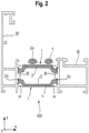
- a cross-sectional view perpendicular to the longitudinal direction z of another embodiment of the metal plastic composite profile with another embodiment of a plastic profile with an metal containing layer;
- Fig. 3
- a cross-sectional view perpendicular to the longitudinal direction z of another embodiment of the metal plastic composite profile with another embodiment of a plastic profile with an metal containing layer;
- Fig. 4
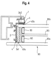
- an embodiment of a window, door, facade or cladding element with an insulating glass unit and a plastic profile according to another embodiment connected thereto;
- Fig. 5
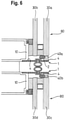
- a cross-sectional view of a connecting area of a structural glazing element as one embodiment of a window, door, facade or cladding element with other embodiments of plastic profiles with metal containing layers;
- Fig. 6
- a cross-sectional view of another embodiment of a metal-plastic composite profile with other embodiments of plastic profiles with an metal containing layer as an example of window, door, facade and cladding elements;
- Fig. 7
- a schematic drawing of a supersonic cold spray apparatus;
- Fig. 8
- in a) a schematic drawing of a supersonic cold spray deposition, in b) a schematic 3D drawing of a supersonic cold spray deposition on an insulating strip, and in c) a schematic 3D drawing of the planes involved in a supersonic cold spray deposition on an insulating strip; and
- Fig. 9
- a cross-sectional view of another embodiment of a metal-plastic composite profile with another embodiment of plastic profiles with a metal containing layer as an example of window, door, facade and cladding elements.
-
Figs. 1 ,2 and3 show different embodiments of metal-plastic composite profiles 100. InFigs. 1 and2 , afirst metal profile 10 and asecond metal profile 20 are connected by two insulating strips orinsulating webs 1. - The insulating strips (profiles) 1 each comprise a
body 2 made of a thermoplastic material. Theinsulating strips 1 and theirprofile bodies 2 extend in a longitudinal direction z and have an essentially constant cross-section in the planes x-y perpendicular to the longitudinal direction z. Essentially constant means that interruptions or holes or the same could be present as exemplified inUS 7,913,470 B2 but that the cross-sectional shape is, except for such recesses, holes or the like, the same along the longitudinal direction z. The same applies to themetal profiles - The
profile bodies 2 of theinsulating strips 1 comprise at each of the two edges extending in the longitudinal direction z on the two lateral sides in the lateral direction, one roll-inhead corresponding grooves metal profiles head Fig. 3 ofUS 7,913,470 B2 . - A pressure plate design for claddings such as the one disclosed in
EP 1 596 023 B1 - As shown in detail at the
insulating strip 1 and itsprofile body 2 in the upper part ofFig. 1 , anouter surface 2a of theprofile body 2 is covered with a metal containing layer (hereinafter also referred to as inorganic containing layer) 4. InFig 1 , the representation of the inorganic containinglayer 4 is removed in the front part of theouter surface 2a, but this is only for illustrational purposes. In the embodiment, the exposed part of theouter surface 2a is completely covered with the inorganic containinglayer 4. - In
Fig. 2 , a corresponding configuration is shown and the same reference numerals designate corresponding parts. As can be seen in the cross-section x-y inFig. 2 , the inorganic containinglayer 4 is deposited at least on onesurface 2a of theprofile body 2 of the insulating strips 1. In the configuration shown inFig. 2 (and inFig. 1 ), the reason is that this surface is exposed to the environment and should be, for example, powder coated. - The embodiment shown in
Fig. 3 has only onemetal profile 10, to which another embodiment of aplastic profile 1 with abody 2 made from thermoplastic material is connected by rolling-in. The plastic profile comprises a wider roll-inhead 2e and all outer surfaces, which are not rolled-in, are covered with the inorganic containinglayer 4. - Many other types of
profiles 1 withbodies 2 made of thermoplastic material for use in window, door, facade or cladding element applications can be used with invention, and some other applications will be described in more detail further below. Before describing the same, the characteristics of the profile bodies and the inorganic containing layers and the corresponding methods of manufacturing are described. - In general, the
plastic profile bodies 2 can be manufactured by extrusion as known in the art. Preferred materials for the embodiments are polyamide (PA), polyethylene (PE), polybutylene terephthalate (PBT), acrylonitrile styrene acrylate (ASA) with or without reinforcing materials such as fibres, e.g., glass fibres, carbon fibres, aramid fibres, basalt fibres and so on with a fibre content in the range from 5 to 60 %, preferred 20 to 40%. Especially preferred is PA 66 with a glass fibre content in the range from 5 to 60 %, preferred 20 to 30%, especially 25 %. Other thermoplastic materials than the ones indicated above can be used, but the above are preferred at present. - The inorganic containing layer is formed of metal containing materials selected from aluminium, alumina, tin, copper and mixtures (blends) of these materials. The preferred material composition is, at present, a layer made of aluminium or tin or copper or mixtures thereof, especially aluminium or a mixture of aluminium and tin in combination with PA 66 with the above glass fibre reinforcement.
- The inorganic containing
layer 4 is formed on the, e.g. extruded,body 2 of thermoplastic material by a supersonic cold spray process which may be one developed by CenterLine (Windsor) Ltd., Ontario, Canada and described, e.g., by Ye and Wang in Materials Letters 137 (2014), Elsevier B. V., pages 21 to 24. - A schematic representation of a corresponding supersonic cold spray system is shown in
Fig. 7 . For the purpose of depositing the inorganic containinglayers 4 of the embodiments, the inorganic containing materials are present as a powder. The powder is made of particles with spherical or irregular volumetric shapes, where the particle size medium diameter is in a range between 1 and 270 µm to obtain deposited layers with thicknesses in a range of 30 µm to 450 µm. The particles are accelerated in a supersonic nozzle configuration to speeds at gas pressures between 4 and 50 bar. The temperature of the gas flow into which the powder particles are inserted is in the range between 280 and 690 K in usual cases, preferably between 280 K and 410K. - As shown in the schematic drawing of
Fig. 8 a) , a deposition of an inorganic containing layer on a thermoplastic substrate is preferably made by using the particles accelerated by the supersonic cold spray system 200, the nozzle 201 of which is shown. The acceleratedparticles 202 are ejected with a particle speed vp at an angle α relative to the surface of thesubstrate 2 which angle α is in the range from 60° to 120°. Thesubstrate 2 is moved at a substrate speed vs in a range from 20.0 mm/s to 50,000.0 mm/s.Fig. 8 b) shows a schematic 3D drawing of the supersonic cold spray deposition on an insulatingstrip 2, andFig. 8 c) shows a schematic 3D drawing of the planes involved in the supersonic cold spray deposition on the insulatingstrip 2 ofFig. 8 b) . As it is obvious fromFig. 8 b) and c) , the supersonic cold spray deposition on the insulatingstrip 2 is essentially effected in that the acceleratedparticles 202 are ejected with a particle speed vp in a particle plane pp at an angle α relative to the plane sp of the substrate surface on which the layer is to be deposited. Preferably, as shown inFig. 8 b) and c) , the particle speed vp and the substrate surface speed vs lie in a plane including the angle α. Therefore, in the representation inFig. 8 b) and c) , the x-z plane includes thesubstrate surface 2 and the substrate surface speed vs, the particle plane pp is at an angle α relative to the x-z plane and perpendicular to the y-z plane, and the substrate surface speed vs and the particle speed vp span a plane parallel to the y-z plane. - Depending on the powder feed load (mass/time) into the gas flow and the medium particle size as well as the thickness of the deposited layer, the continuity (coverage of the surface of the profile body) can be from almost non-continuous to completely continuous. Preferred is a complete continuity. If continuity should be achieved for layers with lower thicknesses such as 40 µm, the medium particle size should be a third or less of the intended thickness of the deposited layer.
- The mechanism of the particle deposition on thermoplastics is believed to have two stages, namely an initial deposition by embedding particles into the surface of the thermoplastic material and a successive deposition on the embedded particles. Depending on the type and size of the inorganic containing particles as well as the type of the thermoplastic material, in particular the hardness of the thermoplastic material, the process conditions have to be set such that the particle jet of the supersonic cold spray slightly erodes the surface of the thermoplastic material, allowing some of the particles to stay entrapped upon impacting onto the profile body. Once particles are embedded/entrapped, the feed rate may be increased in order to increase continuous embedment and finally achieve successive deposition on the embedded particles by sticking of particles to the embedded particles.
- Due to the mechanism of the layer deposition, the interface between the thermoplastic material and the inorganic containing layer seen in cross-section shows an impact eroded surface of the thermoplastic material due to impact erosion filled with inorganic containing material entrapped in the impact eroded surface.
-
Fig. 4 shows another embodiment of a window, door, facade or cladding element with a profile body of thermoplastic material with an inorganic containing layer thereon. In detail, a triple glazing insulating glass unit (IGU) 90 comprises threeglass panes spacers 60 which are connected to the glass panes by primary and secondary sealants as known in the art. TheIGU 90 is a stepped IGU, meaning that one of theouter glass panes 30a protrudes in the cross-section in comparison to the otherouter glass pane 30b. At the edge of theIGU 90, thethermal break profile 1 comprising aprofile body 2 made of a thermoplastic material is attached. Two portions 2a1 and 2a2 of theouter surface 2a of theprofile body 2 comprise an inorganic containinglayer 4 deposited thereon as described before. Themetal containing layer 4 on the surface portion 2a1 allows to connect theprofile body 2 to a glazing sealing 40a, which may be a weather sealing or a structural sealing, by adhesive in a safe manner. As well known in the art, it is difficult to connect thermoplastic materials to glass or to glazing sealings or to a metal profile by adhesive in a long-term stable manner. This disadvantage can be overcome by the inorganic containing layer, which is strongly connected to theprofile body 2 as described before. - The same essentially applies to the connection of the
profile body 2 with a structural double side tape or structural silicone sealing 40b at the indoor side ofglass pane 30b. Again, a long-term stable connection through adhesive between themetal containing layer 4 deposited on the outer surface portion 2a2 and the sealing 40b is made possible. Sealing/sealant -
Fig. 5 shows a cross-section of a portion of a typical structural glazing detail, to which the present invention has been applied. A first double-glazing IGU 90 of the stepped type comprises twoglass panes spacer 60 and connected via aprimary sealant 61 andsecondary sealant 62 to form theIGU 90. In the lower part ofFig. 5 , a second double-glazing IGU 80 of the non-stepped conventional type is shown, which comprises twoglass panes - Stepped
IGU 90 is connected to a first thermal break profile 1 (1a) at several portions. At one portion of theouter surface 2a of theprofile body 2, an inorganic containinglayer 4 is applied, which faces the inner side of the protrudingglass pane 30a. The protrudingglass pane 30a is connected to this portion of theprofile body 2 carrying the inorganic containinglayer 4 via a structural silicone or structural double side tape sealing 40a and adhesive in the same way as described before with respect toFig. 4 . In addition, next to thesealing 40a, the double-sidedadhesive foam tape 70 is attached to the protrudingglass pane 30a and to a part of the inorganic containinglayer 4. Asilicone setting block 71 is positioned between another portion of theprofile body 2 and theIGU 90, while agasket 50a made of silicone is connected to theprofile body 2 and abuts theglass pane 30b. - The
second IGU 80 is connected to a second profile 1 (lb) having athermoplastic profile body 2, which, in the cross-section, is essentially U-shaped. On one outer side of a leg of the U-shape, an inorganic containinglayer 4 is deposited in the described manner. This enables to connect theprofile body 2 in a long-term stable manner via adhesive to another structural silicone sealing 40b, as shown inFig. 5 . - It becomes clear from
Figs. 4 and5 , that the depositing of the inorganic containinglayer 4 on theprofile body 2 of thermoplastic material is not only useful to allow powder coating or the like in inorganic plastic composite profiles for window, door, facade and cladding elements but also to fulfil the long-felt need to enable long-term stable adhesive connections between IGUs and profile bodies made from thermoplastic material. The two IGUs are connected and the interspace is sealed by another sealing 40c, to which a closed cell polyethylene backer material is attached. Of course, although not shown, the polyethylene backer material could also be provided with an inorganic containinglayer 4 manufactured as described before. -
Fig. 6 shows another example of applying the teaching of the present invention to connecting IGUs with profile bodies of thermoplastic material via adhesive. As the construction on the upper and lower side ofFig. 6 is the same, we only describe the upper part in detail. A double-glazing IGU 80 comprises twoglass panes outer glass pane 30a is provided with a weather sealing 40a.Profile 1 having aprofile body 2 of thermoplastic material is provided with an inorganic containinglayer 4 of the described type on its outer surface facing the sealing 40a. This enables again in the described manner a connection by adhesive between thethermoplastic profile body 2 and thesealing 40a which is long-term stable. Theprofile 1 can also be connected to ametal profile 10 forming part of the building structure by known means, but it is also possible to deposit an inorganic containinglayer 4 on theouter surface 2a of theprofile body 2 facing themetal profile 10, again enabling a long-term stable connection by adhesive as an option. The sealing/sealant - In the embodiment of
Fig.6 , the sealing/sealant 40a/40b could be applied to an insulating panel instead of an IGU. - Summarizing, an inorganic containing
layer 4 can be deposited on aprofile body 2 made of a thermoplastic material as described above. The layer thickness can be from 30 µm to 450 µm, preferably it is in the range from 30 µm to 70 µm. The layer can be deposited with a thickness which is difficult to achieve with other methods and with a mechanical connection strength for such a thick layer which is even more difficult to achieve if not impossible with a previously known method. - The corresponding inorganic containing
layer 4 allows connection by adhesives between thermoplastic profile bodies on one side and glass or metal or a sealant on the other side in a long-term stable manner, which has been difficult to achieve with previous technologies. Rigid interconnection has values between 350 N/m to 24520 N/m linear meter for powders and glueings. - The embodiment of
Fig. 9 shows an inorganic containinglayer 4 that allows a connection by adhesives between athermoplastic profile body 2 connected to ametal profile thermoplastic profile body 2 on the other side in a long-term stable manner that has mechanical connection strength values in a range from 1 × 10⁶ N/m2 to 96 × 106 N/m2. - The inorganic containing layer allows electrostatic coating such as power coating, allows to provide electrical conductivity and/or resistivity to the corresponding profiles, allows to provide electrical circuitry, allows to provide welding between wires and surface, allows to provide magnetic properties by using corresponding magnetic particles, allows to provide a gas barrier if the layer is made continuous, allows to provide a bacteria and microbiology resistance in high quality, and improves a shear resistance or sliding between the metal and thermoplastic parts in thermal breaks for window, door, facade and cladding elements.
- The inorganic containing layer allows equipotential bonding between
metal profiles thermoplastic profiles 1 or from athermoplastic profile 1 to ainternal metal profile 10 being a protection against electric shock in facades of buildings and avoiding dangerous touch voltages, by connecting the outer part of building to the inner part between the metal and thermoplastic parts in thermal breaks for window, door, facade and cladding elements, and then discharging the electricity to the ground. Equipotential between the cladding and the inner furthest corresponding metal framing component in each building floor is measured with prospective current of 200 mA.
Claims (15)
- Profile for window, door, facade or cladding elements, comprising a profile body (2) made from thermoplastic material and extending in a longitudinal direction (z) with an essentially constant cross-section (x-y) along the longitudinal direction (z) and having at least one outer surface (2a), anda metal containing layer (4) deposited on at least part of the at least one outer surface (2a),wherein the thermoplastic material comprises at least one thermoplastic selected from the group containing polyamide 66 with 5 to 60% glass fiber reinforcement, polyethylene, polypropylene, polybutylene terephthalate, acrylonitrile styrene acrylate,wherein the metal containing layer is made of aluminium or alumina or tin or copper or blends thereof,wherein the metal containing layer (4) is deposited directly on the profile body (2) using a cold spray technology, andwherein the metal containing layer has a thickness in the range from 30 µm to 450 µm.
- Profile according to claim 1, wherein the interface between the thermoplastic material and the metal containing material is formed by an impact eroded surface of the thermoplastic material and metal containing material entrapped in the impact eroded surface of the thermoplastic material.
- Profile according to one of claims 1 to 2, wherein the thermoplastic material is polyamide 66 with 20 to 60% glass fibre reinforcement.
- Profile according to one of claims 1 to 3, wherein the metal containing layer is made of aluminium or alumina or blends thereof.
- Profile according to one of claims 1 to 3, wherein the metal containing layer is made of aluminium and tin.
- Profile according to one of claims 1 to 3, wherein the metal containing layer is made of copper.
- Profile according to one of claims 1 to 6, wherein the metal containing layer has a thickness in the range from 30 µm to 70 µm.
- Profile according to one of claims 1 to 7, wherein the profile body (2) is made fully or partly from foamed thermoplastic material.
- Profile according to claim 8, wherein the profile body comprises a foamed thermoplastic material with a low density of foam cells of less than 10% in volume or no foam cells in a layer of a thickness of 0.1 mm at the at least one outer surface (2a).
- Method for manufacturing a profile for window, door, facade or cladding elements comprising a profile body (2) made from thermoplastic material and extending in a longitudinal direction (z) with an essentially constant cross-section (x-y) along the longitudinal direction (z) and having at least one outer surface (2a), and a metal containing layer (4) deposited on at least part of the at least one outer surface (2a), comprising the steps of:- extruding the profile body from a thermoplastic material comprising at least one thermoplastic selected from the group containing polyamide 66 with 5 to 60% glass fiber reinforcement, polyethylene, polybutylene terephthalate, acrylonitrile styrene acrylate,- generating a supersonic cold spray of metal containing particles made of aluminium or alumina or tin or copper or blends thereof, and- directing the supersonic cold spray of the metal containing particles at a temperature in a range from 280 K to 690 K and at a pressure of 4 bar to 50 bar to the at least one outer surface (2a) of the profile body (2) moving at a substrate speed (vs) in the range of 20 to 50000 mm/s to deposit the metal containing layer (4) having a thickness in the range from 30 µm to 450 µm.
- Method according to claim 10, wherein the supersonic cold spray of the metal containing particles is directed to the at least one outer surface (2a) of the profile body (2) at an angle α relative to the surface, which angle α is in the range from 60° to 120°.
- Method according to claim 10 or 11, wherein the metal containing layer has a thickness in the range from 30 µm to 70 µm.
- Metal plastic composite profile for window, door, facade or cladding elements, comprising
at least one metal profile (10, 20) and at least one profile according to one of claims 1 to 9 connected to the metal profile via adhesive applied between the metal containing layer (4) facing the metal profile (10) and the metal profile. - Window, door, facade or cladding element comprising
a glass pane or insulating pane (30a, 30b, 30c, 30d), a sealing element (40, 40a, 40b, 40c), and at least one profile according to one of claims 1 to 9, wherein the glass pane is connected to the at least one outer surface (2a) of the profile via the seal element (40, 40a, 40b, 40c) and an adhesive between the sealing element and the metal containing layer (4). - Window, door, facade or cladding element comprising
a glass pane or insulating pane (30a, 30b, 30c, 30d), a sealing element (40, 40a, 40b, 40c), and a metal plastic composite profile according to claim 13, wherein the metal containing layer (4) is also deposited at least on a part of the outer surface facing the sealing element and the glass pane is connected to the at least one outer surface (2a) of the profile via the seal element (40, 40a, 40b, 40c) and an adhesive between the sealing element and the metal containing layer (4).
Priority Applications (1)
| Application Number | Priority Date | Filing Date | Title |
|---|---|---|---|
| PL18729621T PL3631135T3 (en) | 2017-05-31 | 2018-05-30 | Profile for window, door, facade and cladding element and method for its manufacturing |
Applications Claiming Priority (2)
| Application Number | Priority Date | Filing Date | Title |
|---|---|---|---|
| EP17173834 | 2017-05-31 | ||
| PCT/EP2018/064293 WO2018220078A1 (en) | 2017-05-31 | 2018-05-30 | Profile for window, door, facade and cladding elements |
Publications (2)
| Publication Number | Publication Date |
|---|---|
| EP3631135A1 EP3631135A1 (en) | 2020-04-08 |
| EP3631135B1 true EP3631135B1 (en) | 2022-02-09 |
Family
ID=59061818
Family Applications (1)
| Application Number | Title | Priority Date | Filing Date |
|---|---|---|---|
| EP18729621.5A Active EP3631135B1 (en) | 2017-05-31 | 2018-05-30 | Profile for window, door, facade and cladding element and method for its manufacturing |
Country Status (11)
| Country | Link |
|---|---|
| US (1) | US11142942B2 (en) |
| EP (1) | EP3631135B1 (en) |
| JP (1) | JP7072005B2 (en) |
| KR (1) | KR102762455B1 (en) |
| CN (1) | CN110914511A (en) |
| AU (1) | AU2018276407B2 (en) |
| CA (1) | CA3064793C (en) |
| ES (1) | ES2907245T3 (en) |
| PL (1) | PL3631135T3 (en) |
| PT (1) | PT3631135T (en) |
| WO (1) | WO2018220078A1 (en) |
Cited By (1)
| Publication number | Priority date | Publication date | Assignee | Title |
|---|---|---|---|---|
| EP4575165A1 (en) * | 2023-12-22 | 2025-06-25 | REHAU Industries SE & Co. KG | Hollow window or door chamber profile and method for its production |
Families Citing this family (10)
| Publication number | Priority date | Publication date | Assignee | Title |
|---|---|---|---|---|
| US9335296B2 (en) | 2012-10-10 | 2016-05-10 | Westinghouse Electric Company Llc | Systems and methods for steam generator tube analysis for detection of tube degradation |
| BE1027154B1 (en) * | 2019-03-15 | 2020-11-05 | Claeys Stephanie Catharina R | Curtain wall |
| US11935662B2 (en) | 2019-07-02 | 2024-03-19 | Westinghouse Electric Company Llc | Elongate SiC fuel elements |
| KR102523509B1 (en) | 2019-09-19 | 2023-04-18 | 웨스팅하우스 일렉트릭 컴퍼니 엘엘씨 | Apparatus and Method of Use for Performing In Situ Adhesion Testing of Cold Spray Deposits |
| US11248412B2 (en) * | 2019-11-18 | 2022-02-15 | Rehme Custom Doors & Lighting, Inc. | Metallic fenestration systems with improved thermal performance and methods of manufacturing same |
| CN111489513B (en) * | 2020-04-22 | 2021-09-10 | 上海步阳科技股份有限公司 | Anti-theft alarm security door |
| CN112796619A (en) * | 2020-12-28 | 2021-05-14 | 安徽科蓝特铝业有限公司 | Energy-saving and environment-friendly aluminum alloy profile for doors and windows |
| USD960392S1 (en) * | 2020-12-29 | 2022-08-09 | Asas Alüminyum Sanayi ve Ticaret Anonim Sirketi | Window wall system frame profile |
| KR102633635B1 (en) * | 2023-05-26 | 2024-02-02 | 장화석 | Aluminum system window for fireproof |
| EP4617464A1 (en) * | 2024-03-12 | 2025-09-17 | Hydro Building Systems Lüdenscheid GmbH | Fire resistant profile frame construction |
Citations (3)
| Publication number | Priority date | Publication date | Assignee | Title |
|---|---|---|---|---|
| WO2001048346A1 (en) * | 1999-12-24 | 2001-07-05 | Wilfried Ensinger | Plastic filled or hollow chamber profiles, especially for composite profiles |
| US20130129976A1 (en) * | 2009-11-12 | 2013-05-23 | Mtu Aero Engines Gmbh | Coating plastic components by means of kinetic cold gas spraying |
| FR2995323A1 (en) * | 2012-09-11 | 2014-03-14 | Renault Sa | Forming a metal coating on surface of thermoplastic substrate of composite material used in e.g. decoration field, by increasing the surface roughness of substrate by laser ablation, and projecting metal particles to surface of substrate |
Family Cites Families (29)
| Publication number | Priority date | Publication date | Assignee | Title |
|---|---|---|---|---|
| DE3236357A1 (en) | 1982-10-01 | 1984-04-05 | Wilfried Dipl.-Ing. 7031 Nufringen Ensinger | Process for connecting the metallic inner and outer parts of a composite section by an insulating web of plastic |
| DE3332618A1 (en) * | 1983-09-09 | 1985-03-21 | Josef Gartner & Co, 8883 Gundelfingen | COMPOSITE PROFILE |
| JPS60233287A (en) * | 1983-09-09 | 1985-11-19 | ヨ−ゼフ ガルトナ− アンド カンパニ− | Asembled profile |
| JPS6280042A (en) * | 1985-10-04 | 1987-04-13 | 株式会社トクヤマ | Flame-retardant synthetic resin member |
| DE3801564A1 (en) | 1988-01-20 | 1989-08-03 | Wilfried Ensinger | Plastic insulating web |
| DE3939968A1 (en) | 1989-12-02 | 1991-06-06 | Schueco Int Gmbh & Co | COMPOSITE PROFILE, ESPECIALLY FOR WINDOWS, DOORS AND FACADES |
| DE4323480C2 (en) | 1993-07-14 | 1996-11-14 | Wilfried Ensinger | Process for powder coating composite profiles and composite profile |
| US5945048A (en) | 1995-03-25 | 1999-08-31 | Ensinger; Wilfried | Process and device for extruding polymer melts to form hollow chamber sections |
| JP3187686B2 (en) * | 1995-08-04 | 2001-07-11 | 河西工業株式会社 | Automotive interior parts |
| JP3137582B2 (en) * | 1996-07-19 | 2001-02-26 | トステム株式会社 | Manufacturing method of heat insulation mold |
| DE19637858A1 (en) * | 1996-09-17 | 1998-04-02 | Schueco Int Kg | Insulated composite profile for doors, windows or facades |
| JPH10196228A (en) * | 1997-01-10 | 1998-07-28 | Fujisash Co | Insulated window frame |
| JPH1130075A (en) * | 1997-07-10 | 1999-02-02 | Otsuka Chem Co Ltd | Window frame |
| DE19921458B4 (en) | 1999-05-08 | 2009-12-24 | Technoform Caprano + Brunnhofer Ohg | Method and device for producing a hollow chamber profile made of thermoplastic material according to the cooling nozzle method |
| DE10043526C1 (en) | 2000-09-05 | 2002-06-06 | Fraunhofer Ges Forschung | Process for adhesive metal coating and metal-coated functional element |
| DE202004007805U1 (en) | 2004-05-14 | 2004-07-29 | SCHÜCO International KG | Pressure profile and facade or skylight construction |
| JP2005334833A (en) | 2004-05-31 | 2005-12-08 | Kubota Matsushitadenko Exterior Works Ltd | Coating method for inorganic plate |
| BRPI0512518A (en) | 2004-06-23 | 2008-03-11 | Norsk Hydro As | structural metal element |
| US20060121187A1 (en) | 2004-12-03 | 2006-06-08 | Haynes Jeffrey D | Vacuum cold spray process |
| US20100119707A1 (en) * | 2006-02-28 | 2010-05-13 | Honeywell International, Inc. | Protective coatings and coating methods for polymeric materials and composites |
| DE102006061035C5 (en) | 2006-12-22 | 2014-09-04 | Technoform Bautec Holding Gmbh | Plastic profile for window, door and facade elements |
| DE202007016649U1 (en) | 2007-04-02 | 2008-04-30 | Technoform Caprano Und Brunnhofer Gmbh & Co. Kg | Ladder-shaped insulating bar for a composite profile for window, door and facade elements and composite profile for window, door and facade elements |
| JP5380665B2 (en) | 2008-06-06 | 2014-01-08 | 株式会社Lixil | Thermal insulation sash |
| DE102010016926A1 (en) | 2009-05-16 | 2010-12-30 | Eichler Gmbh & Co.Kg | Electrostatic lacquering of electrically non-conductive parts e.g. plastic-, glass- or ceramic parts by surface conductivity-producing layers, comprises dryly coating non-conductive parts with metal conducting and semi-conducting layers |
| DE102011110899A1 (en) | 2011-08-17 | 2013-02-21 | Technoform Bautec Holding Gmbh | Paintable insulating bar for a composite profile for window, door or façade elements |
| AU2013243224C1 (en) * | 2012-04-04 | 2018-02-01 | Commonwealth Scientific And Industrial Research Organisation | A process for producing a titanium load-bearing structure |
| DE202012010135U1 (en) * | 2012-10-23 | 2012-11-22 | Technoform Bautec Holding Gmbh | Insulating strip for a composite profile for window, door or facade elements and composite profile for window, door or facade elements with insulating strip |
| JP2015105394A (en) | 2013-11-29 | 2015-06-08 | 株式会社日立製作所 | Glass coated composite material, and method and apparatus for manufacturing the same |
| CN203872476U (en) * | 2014-02-21 | 2014-10-08 | 亚超特工业有限公司 | Metal housing of electronic device |
-
2018
- 2018-05-30 CN CN201880047370.7A patent/CN110914511A/en active Pending
- 2018-05-30 KR KR1020197038811A patent/KR102762455B1/en active Active
- 2018-05-30 JP JP2019565824A patent/JP7072005B2/en active Active
- 2018-05-30 ES ES18729621T patent/ES2907245T3/en active Active
- 2018-05-30 PL PL18729621T patent/PL3631135T3/en unknown
- 2018-05-30 EP EP18729621.5A patent/EP3631135B1/en active Active
- 2018-05-30 WO PCT/EP2018/064293 patent/WO2018220078A1/en not_active Ceased
- 2018-05-30 CA CA3064793A patent/CA3064793C/en active Active
- 2018-05-30 PT PT187296215T patent/PT3631135T/en unknown
- 2018-05-30 AU AU2018276407A patent/AU2018276407B2/en active Active
- 2018-05-30 US US16/617,762 patent/US11142942B2/en active Active
Patent Citations (3)
| Publication number | Priority date | Publication date | Assignee | Title |
|---|---|---|---|---|
| WO2001048346A1 (en) * | 1999-12-24 | 2001-07-05 | Wilfried Ensinger | Plastic filled or hollow chamber profiles, especially for composite profiles |
| US20130129976A1 (en) * | 2009-11-12 | 2013-05-23 | Mtu Aero Engines Gmbh | Coating plastic components by means of kinetic cold gas spraying |
| FR2995323A1 (en) * | 2012-09-11 | 2014-03-14 | Renault Sa | Forming a metal coating on surface of thermoplastic substrate of composite material used in e.g. decoration field, by increasing the surface roughness of substrate by laser ablation, and projecting metal particles to surface of substrate |
Non-Patent Citations (1)
| Title |
|---|
| PETER C. KING ET AL: "Embedment of copper particles into polymers by cold spray", SURFACE AND COATINGS TECHNOLOGY, vol. 216, 1 February 2013 (2013-02-01), AMSTERDAM, NL, pages 60 - 67, XP055530781, ISSN: 0257-8972, DOI: 10.1016/j.surfcoat.2012.11.023 * |
Cited By (1)
| Publication number | Priority date | Publication date | Assignee | Title |
|---|---|---|---|---|
| EP4575165A1 (en) * | 2023-12-22 | 2025-06-25 | REHAU Industries SE & Co. KG | Hollow window or door chamber profile and method for its production |
Also Published As
| Publication number | Publication date |
|---|---|
| JP7072005B2 (en) | 2022-05-19 |
| AU2018276407A1 (en) | 2019-12-19 |
| PT3631135T (en) | 2022-03-01 |
| CN110914511A (en) | 2020-03-24 |
| PL3631135T3 (en) | 2022-05-16 |
| NZ759343A (en) | 2025-03-28 |
| US11142942B2 (en) | 2021-10-12 |
| EP3631135A1 (en) | 2020-04-08 |
| CA3064793C (en) | 2023-07-18 |
| AU2018276407B2 (en) | 2022-07-07 |
| US20200102782A1 (en) | 2020-04-02 |
| WO2018220078A1 (en) | 2018-12-06 |
| ES2907245T3 (en) | 2022-04-22 |
| KR20200015918A (en) | 2020-02-13 |
| KR102762455B1 (en) | 2025-02-06 |
| CA3064793A1 (en) | 2018-12-06 |
| JP2020521898A (en) | 2020-07-27 |
Similar Documents
| Publication | Publication Date | Title |
|---|---|---|
| US11142942B2 (en) | Profile for window, door, facade and cladding elements | |
| EP3631134B1 (en) | Profile for window, door, facade and cladding elements | |
| CN101688421B (en) | Ladder-shaped insulating sheets for composite profiles of windows, doors and building facades and composite profiles for windows, doors and building facades | |
| US5466534A (en) | Metal-polymer composite insulative spacer for glass members and insulative window containing same | |
| US5487937A (en) | Metal-polymer composite insulative spacer for glass members and insulative window containing same | |
| EP3934094A1 (en) | Building-integrated photovoltaic system | |
| US20250207455A1 (en) | Window or door hollow chamber profile and method for producing the same | |
| CA3064791C (en) | Profile for window, door, facade and cladding elements | |
| EP1799948B1 (en) | Sash bar suitable for insulating window units | |
| EP3314065B1 (en) | Curtain wall mullions, transoms and systems | |
| CN216974557U (en) | Heat insulation strip, profile and door and window | |
| US20200347667A1 (en) | Insulating panel assembly | |
| CN215716399U (en) | Unit plate curtain wall connecting structure | |
| US20260034769A1 (en) | Glazing comprising a first and second channel-section glazing element | |
| CN211370034U (en) | Aluminum alloy door and window | |
| GB2559406A (en) | Double glazing unit and method | |
| NZ759343B2 (en) | Profile for window, door, facade and cladding elements | |
| CN119843963A (en) | High-strength heat-insulation combined door and window and manufacturing method thereof |
Legal Events
| Date | Code | Title | Description |
|---|---|---|---|
| STAA | Information on the status of an ep patent application or granted ep patent |
Free format text: STATUS: UNKNOWN |
|
| STAA | Information on the status of an ep patent application or granted ep patent |
Free format text: STATUS: THE INTERNATIONAL PUBLICATION HAS BEEN MADE |
|
| PUAI | Public reference made under article 153(3) epc to a published international application that has entered the european phase |
Free format text: ORIGINAL CODE: 0009012 |
|
| STAA | Information on the status of an ep patent application or granted ep patent |
Free format text: STATUS: REQUEST FOR EXAMINATION WAS MADE |
|
| 17P | Request for examination filed |
Effective date: 20191218 |
|
| AK | Designated contracting states |
Kind code of ref document: A1 Designated state(s): AL AT BE BG CH CY CZ DE DK EE ES FI FR GB GR HR HU IE IS IT LI LT LU LV MC MK MT NL NO PL PT RO RS SE SI SK SM TR |
|
| AX | Request for extension of the european patent |
Extension state: BA ME |
|
| RIN1 | Information on inventor provided before grant (corrected) |
Inventor name: HEZHOU, YE Inventor name: CEMALOVIC, IGOR Inventor name: JIANGFENG, WANG Inventor name: ORTUZAR, XAVIER |
|
| RAP1 | Party data changed (applicant data changed or rights of an application transferred) |
Owner name: TECHNOFORM BAUTEC HOLDING GMBH |
|
| DAV | Request for validation of the european patent (deleted) | ||
| DAX | Request for extension of the european patent (deleted) | ||
| TPAC | Observations filed by third parties |
Free format text: ORIGINAL CODE: EPIDOSNTIPA |
|
| STAA | Information on the status of an ep patent application or granted ep patent |
Free format text: STATUS: EXAMINATION IS IN PROGRESS |
|
| 17Q | First examination report despatched |
Effective date: 20210118 |
|
| GRAP | Despatch of communication of intention to grant a patent |
Free format text: ORIGINAL CODE: EPIDOSNIGR1 |
|
| STAA | Information on the status of an ep patent application or granted ep patent |
Free format text: STATUS: GRANT OF PATENT IS INTENDED |
|
| INTG | Intention to grant announced |
Effective date: 20211109 |
|
| GRAS | Grant fee paid |
Free format text: ORIGINAL CODE: EPIDOSNIGR3 |
|
| GRAA | (expected) grant |
Free format text: ORIGINAL CODE: 0009210 |
|
| STAA | Information on the status of an ep patent application or granted ep patent |
Free format text: STATUS: THE PATENT HAS BEEN GRANTED |
|
| AK | Designated contracting states |
Kind code of ref document: B1 Designated state(s): AL AT BE BG CH CY CZ DE DK EE ES FI FR GB GR HR HU IE IS IT LI LT LU LV MC MK MT NL NO PL PT RO RS SE SI SK SM TR |
|
| REG | Reference to a national code |
Ref country code: GB Ref legal event code: FG4D |
|
| REG | Reference to a national code |
Ref country code: CH Ref legal event code: EP Ref country code: AT Ref legal event code: REF Ref document number: 1467615 Country of ref document: AT Kind code of ref document: T Effective date: 20220215 |
|
| REG | Reference to a national code |
Ref country code: PT Ref legal event code: SC4A Ref document number: 3631135 Country of ref document: PT Date of ref document: 20220301 Kind code of ref document: T Free format text: AVAILABILITY OF NATIONAL TRANSLATION Effective date: 20220221 |
|
| REG | Reference to a national code |
Ref country code: IE Ref legal event code: FG4D |
|
| REG | Reference to a national code |
Ref country code: DE Ref legal event code: R096 Ref document number: 602018030571 Country of ref document: DE |
|
| REG | Reference to a national code |
Ref country code: ES Ref legal event code: FG2A Ref document number: 2907245 Country of ref document: ES Kind code of ref document: T3 Effective date: 20220422 |
|
| REG | Reference to a national code |
Ref country code: LT Ref legal event code: MG9D |
|
| REG | Reference to a national code |
Ref country code: NL Ref legal event code: MP Effective date: 20220209 |
|
| REG | Reference to a national code |
Ref country code: AT Ref legal event code: MK05 Ref document number: 1467615 Country of ref document: AT Kind code of ref document: T Effective date: 20220209 |
|
| PG25 | Lapsed in a contracting state [announced via postgrant information from national office to epo] |
Ref country code: SE Free format text: LAPSE BECAUSE OF FAILURE TO SUBMIT A TRANSLATION OF THE DESCRIPTION OR TO PAY THE FEE WITHIN THE PRESCRIBED TIME-LIMIT Effective date: 20220209 Ref country code: RS Free format text: LAPSE BECAUSE OF FAILURE TO SUBMIT A TRANSLATION OF THE DESCRIPTION OR TO PAY THE FEE WITHIN THE PRESCRIBED TIME-LIMIT Effective date: 20220209 Ref country code: NO Free format text: LAPSE BECAUSE OF FAILURE TO SUBMIT A TRANSLATION OF THE DESCRIPTION OR TO PAY THE FEE WITHIN THE PRESCRIBED TIME-LIMIT Effective date: 20220509 Ref country code: NL Free format text: LAPSE BECAUSE OF FAILURE TO SUBMIT A TRANSLATION OF THE DESCRIPTION OR TO PAY THE FEE WITHIN THE PRESCRIBED TIME-LIMIT Effective date: 20220209 Ref country code: LT Free format text: LAPSE BECAUSE OF FAILURE TO SUBMIT A TRANSLATION OF THE DESCRIPTION OR TO PAY THE FEE WITHIN THE PRESCRIBED TIME-LIMIT Effective date: 20220209 Ref country code: HR Free format text: LAPSE BECAUSE OF FAILURE TO SUBMIT A TRANSLATION OF THE DESCRIPTION OR TO PAY THE FEE WITHIN THE PRESCRIBED TIME-LIMIT Effective date: 20220209 Ref country code: BG Free format text: LAPSE BECAUSE OF FAILURE TO SUBMIT A TRANSLATION OF THE DESCRIPTION OR TO PAY THE FEE WITHIN THE PRESCRIBED TIME-LIMIT Effective date: 20220509 |
|
| PG25 | Lapsed in a contracting state [announced via postgrant information from national office to epo] |
Ref country code: LV Free format text: LAPSE BECAUSE OF FAILURE TO SUBMIT A TRANSLATION OF THE DESCRIPTION OR TO PAY THE FEE WITHIN THE PRESCRIBED TIME-LIMIT Effective date: 20220209 Ref country code: GR Free format text: LAPSE BECAUSE OF FAILURE TO SUBMIT A TRANSLATION OF THE DESCRIPTION OR TO PAY THE FEE WITHIN THE PRESCRIBED TIME-LIMIT Effective date: 20220510 Ref country code: FI Free format text: LAPSE BECAUSE OF FAILURE TO SUBMIT A TRANSLATION OF THE DESCRIPTION OR TO PAY THE FEE WITHIN THE PRESCRIBED TIME-LIMIT Effective date: 20220209 Ref country code: AT Free format text: LAPSE BECAUSE OF FAILURE TO SUBMIT A TRANSLATION OF THE DESCRIPTION OR TO PAY THE FEE WITHIN THE PRESCRIBED TIME-LIMIT Effective date: 20220209 |
|
| PG25 | Lapsed in a contracting state [announced via postgrant information from national office to epo] |
Ref country code: IS Free format text: LAPSE BECAUSE OF FAILURE TO SUBMIT A TRANSLATION OF THE DESCRIPTION OR TO PAY THE FEE WITHIN THE PRESCRIBED TIME-LIMIT Effective date: 20220609 |
|
| PG25 | Lapsed in a contracting state [announced via postgrant information from national office to epo] |
Ref country code: SM Free format text: LAPSE BECAUSE OF FAILURE TO SUBMIT A TRANSLATION OF THE DESCRIPTION OR TO PAY THE FEE WITHIN THE PRESCRIBED TIME-LIMIT Effective date: 20220209 Ref country code: SK Free format text: LAPSE BECAUSE OF FAILURE TO SUBMIT A TRANSLATION OF THE DESCRIPTION OR TO PAY THE FEE WITHIN THE PRESCRIBED TIME-LIMIT Effective date: 20220209 Ref country code: RO Free format text: LAPSE BECAUSE OF FAILURE TO SUBMIT A TRANSLATION OF THE DESCRIPTION OR TO PAY THE FEE WITHIN THE PRESCRIBED TIME-LIMIT Effective date: 20220209 Ref country code: EE Free format text: LAPSE BECAUSE OF FAILURE TO SUBMIT A TRANSLATION OF THE DESCRIPTION OR TO PAY THE FEE WITHIN THE PRESCRIBED TIME-LIMIT Effective date: 20220209 Ref country code: DK Free format text: LAPSE BECAUSE OF FAILURE TO SUBMIT A TRANSLATION OF THE DESCRIPTION OR TO PAY THE FEE WITHIN THE PRESCRIBED TIME-LIMIT Effective date: 20220209 Ref country code: CZ Free format text: LAPSE BECAUSE OF FAILURE TO SUBMIT A TRANSLATION OF THE DESCRIPTION OR TO PAY THE FEE WITHIN THE PRESCRIBED TIME-LIMIT Effective date: 20220209 |
|
| REG | Reference to a national code |
Ref country code: DE Ref legal event code: R097 Ref document number: 602018030571 Country of ref document: DE |
|
| PG25 | Lapsed in a contracting state [announced via postgrant information from national office to epo] |
Ref country code: AL Free format text: LAPSE BECAUSE OF FAILURE TO SUBMIT A TRANSLATION OF THE DESCRIPTION OR TO PAY THE FEE WITHIN THE PRESCRIBED TIME-LIMIT Effective date: 20220209 |
|
| PLBE | No opposition filed within time limit |
Free format text: ORIGINAL CODE: 0009261 |
|
| STAA | Information on the status of an ep patent application or granted ep patent |
Free format text: STATUS: NO OPPOSITION FILED WITHIN TIME LIMIT |
|
| REG | Reference to a national code |
Ref country code: CH Ref legal event code: PL |
|
| 26N | No opposition filed |
Effective date: 20221110 |
|
| PG25 | Lapsed in a contracting state [announced via postgrant information from national office to epo] |
Ref country code: MC Free format text: LAPSE BECAUSE OF FAILURE TO SUBMIT A TRANSLATION OF THE DESCRIPTION OR TO PAY THE FEE WITHIN THE PRESCRIBED TIME-LIMIT Effective date: 20220209 Ref country code: LU Free format text: LAPSE BECAUSE OF NON-PAYMENT OF DUE FEES Effective date: 20220530 Ref country code: LI Free format text: LAPSE BECAUSE OF NON-PAYMENT OF DUE FEES Effective date: 20220531 Ref country code: CH Free format text: LAPSE BECAUSE OF NON-PAYMENT OF DUE FEES Effective date: 20220531 |
|
| PG25 | Lapsed in a contracting state [announced via postgrant information from national office to epo] |
Ref country code: SI Free format text: LAPSE BECAUSE OF FAILURE TO SUBMIT A TRANSLATION OF THE DESCRIPTION OR TO PAY THE FEE WITHIN THE PRESCRIBED TIME-LIMIT Effective date: 20220209 |
|
| PG25 | Lapsed in a contracting state [announced via postgrant information from national office to epo] |
Ref country code: IE Free format text: LAPSE BECAUSE OF NON-PAYMENT OF DUE FEES Effective date: 20220530 |
|
| PG25 | Lapsed in a contracting state [announced via postgrant information from national office to epo] |
Ref country code: MK Free format text: LAPSE BECAUSE OF FAILURE TO SUBMIT A TRANSLATION OF THE DESCRIPTION OR TO PAY THE FEE WITHIN THE PRESCRIBED TIME-LIMIT Effective date: 20220209 Ref country code: CY Free format text: LAPSE BECAUSE OF FAILURE TO SUBMIT A TRANSLATION OF THE DESCRIPTION OR TO PAY THE FEE WITHIN THE PRESCRIBED TIME-LIMIT Effective date: 20220209 |
|
| PG25 | Lapsed in a contracting state [announced via postgrant information from national office to epo] |
Ref country code: HU Free format text: LAPSE BECAUSE OF FAILURE TO SUBMIT A TRANSLATION OF THE DESCRIPTION OR TO PAY THE FEE WITHIN THE PRESCRIBED TIME-LIMIT; INVALID AB INITIO Effective date: 20180530 |
|
| PG25 | Lapsed in a contracting state [announced via postgrant information from national office to epo] |
Ref country code: MT Free format text: LAPSE BECAUSE OF FAILURE TO SUBMIT A TRANSLATION OF THE DESCRIPTION OR TO PAY THE FEE WITHIN THE PRESCRIBED TIME-LIMIT Effective date: 20220209 |
|
| PG25 | Lapsed in a contracting state [announced via postgrant information from national office to epo] |
Ref country code: TR Free format text: LAPSE BECAUSE OF FAILURE TO SUBMIT A TRANSLATION OF THE DESCRIPTION OR TO PAY THE FEE WITHIN THE PRESCRIBED TIME-LIMIT Effective date: 20220209 |
|
| PGFP | Annual fee paid to national office [announced via postgrant information from national office to epo] |
Ref country code: ES Payment date: 20260618 Year of fee payment: 9 |
|
| PGFP | Annual fee paid to national office [announced via postgrant information from national office to epo] |
Ref country code: GB Payment date: 20260526 Year of fee payment: 9 Ref country code: PL Payment date: 20260521 Year of fee payment: 9 |
|
| PGFP | Annual fee paid to national office [announced via postgrant information from national office to epo] |
Ref country code: IT Payment date: 20260529 Year of fee payment: 9 |
|
| PGFP | Annual fee paid to national office [announced via postgrant information from national office to epo] |
Ref country code: DE Payment date: 20260518 Year of fee payment: 9 |
|
| PGFP | Annual fee paid to national office [announced via postgrant information from national office to epo] |
Ref country code: BE Payment date: 20260521 Year of fee payment: 9 |
|
| PGFP | Annual fee paid to national office [announced via postgrant information from national office to epo] |
Ref country code: PT Payment date: 20260519 Year of fee payment: 9 |
|
| PGFP | Annual fee paid to national office [announced via postgrant information from national office to epo] |
Ref country code: FR Payment date: 20260522 Year of fee payment: 9 |