EP3630628B1 - Behälterbehandlungsmaschine sowie verfahren zum betrieb einer behälterbehandlungsmaschine - Google Patents
Behälterbehandlungsmaschine sowie verfahren zum betrieb einer behälterbehandlungsmaschine Download PDFInfo
- Publication number
- EP3630628B1 EP3630628B1 EP18728369.2A EP18728369A EP3630628B1 EP 3630628 B1 EP3630628 B1 EP 3630628B1 EP 18728369 A EP18728369 A EP 18728369A EP 3630628 B1 EP3630628 B1 EP 3630628B1
- Authority
- EP
- European Patent Office
- Prior art keywords
- motors
- motor
- treatment machine
- container treatment
- drive
- Prior art date
- Legal status (The legal status is an assumption and is not a legal conclusion. Google has not performed a legal analysis and makes no representation as to the accuracy of the status listed.)
- Active
Links
Images


Classifications
-
- B—PERFORMING OPERATIONS; TRANSPORTING
- B67—OPENING, CLOSING OR CLEANING BOTTLES, JARS OR SIMILAR CONTAINERS; LIQUID HANDLING
- B67C—CLEANING, FILLING WITH LIQUIDS OR SEMILIQUIDS, OR EMPTYING, OF BOTTLES, JARS, CANS, CASKS, BARRELS, OR SIMILAR CONTAINERS, NOT OTHERWISE PROVIDED FOR; FUNNELS
- B67C3/00—Bottling liquids or semiliquids; Filling jars or cans with liquids or semiliquids using bottling or like apparatus; Filling casks or barrels with liquids or semiliquids
- B67C3/02—Bottling liquids or semiliquids; Filling jars or cans with liquids or semiliquids using bottling or like apparatus
- B67C3/22—Details
-
- B—PERFORMING OPERATIONS; TRANSPORTING
- B67—OPENING, CLOSING OR CLEANING BOTTLES, JARS OR SIMILAR CONTAINERS; LIQUID HANDLING
- B67C—CLEANING, FILLING WITH LIQUIDS OR SEMILIQUIDS, OR EMPTYING, OF BOTTLES, JARS, CANS, CASKS, BARRELS, OR SIMILAR CONTAINERS, NOT OTHERWISE PROVIDED FOR; FUNNELS
- B67C7/00—Concurrent cleaning, filling, and closing of bottles; Processes or devices for at least two of these operations
- B67C7/0006—Conveying; Synchronising
- B67C7/004—Conveying; Synchronising the containers travelling along a circular path
-
- B—PERFORMING OPERATIONS; TRANSPORTING
- B65—CONVEYING; PACKING; STORING; HANDLING THIN OR FILAMENTARY MATERIAL
- B65C—LABELLING OR TAGGING MACHINES, APPARATUS, OR PROCESSES
- B65C9/00—Details of labelling machines or apparatus
-
- B—PERFORMING OPERATIONS; TRANSPORTING
- B65—CONVEYING; PACKING; STORING; HANDLING THIN OR FILAMENTARY MATERIAL
- B65G—TRANSPORT OR STORAGE DEVICES, e.g. CONVEYORS FOR LOADING OR TIPPING, SHOP CONVEYOR SYSTEMS OR PNEUMATIC TUBE CONVEYORS
- B65G29/00—Rotary conveyors, e.g. rotating discs, arms, star-wheels or cones
-
- B—PERFORMING OPERATIONS; TRANSPORTING
- B67—OPENING, CLOSING OR CLEANING BOTTLES, JARS OR SIMILAR CONTAINERS; LIQUID HANDLING
- B67B—APPLYING CLOSURE MEMBERS TO BOTTLES JARS, OR SIMILAR CONTAINERS; OPENING CLOSED CONTAINERS
- B67B3/00—Closing bottles, jars or similar containers by applying caps
-
- B—PERFORMING OPERATIONS; TRANSPORTING
- B65—CONVEYING; PACKING; STORING; HANDLING THIN OR FILAMENTARY MATERIAL
- B65G—TRANSPORT OR STORAGE DEVICES, e.g. CONVEYORS FOR LOADING OR TIPPING, SHOP CONVEYOR SYSTEMS OR PNEUMATIC TUBE CONVEYORS
- B65G47/00—Article or material-handling devices associated with conveyors; Methods employing such devices
- B65G47/74—Feeding, transfer, or discharging devices of particular kinds or types
- B65G47/84—Star-shaped wheels or devices having endless travelling belts or chains, the wheels or devices being equipped with article-engaging elements
- B65G47/846—Star-shaped wheels or wheels equipped with article-engaging elements
Definitions
- the present invention relates to a container treatment machine with a drive device for rotating a gyroscope on which the containers to be treated can be accommodated.
- the invention also relates to a method for operating the container treatment machine.
- Container handling machines are used, among other things, for the industrial filling, cleaning and closing of containers such as PET bottles.
- the aim of such systems is to ensure the most precise transfer or transport of the containers.
- a container handling machine comprising a carousel for handling objects that can be rotated about a vertical axis and has a stator and a rotor is known.
- the rotor has a gear ring that is driven by pinions of motors that are attached to the stator and are spaced apart from one another.
- the motors can be switched via a control unit to accelerate or decelerate the carousel so that their torques are directed in the same direction, or during normal operation their torques are directed in opposite directions, with the torques always being kept at a constant difference. This limits the carousel's possible uses.
- a rotary machine with a carousel for conveying containers into container receptacles and a unit for treating and/or inspecting the containers has become known.
- This rotary machine is characterized in particular by the fact that the carousel is connected to a gear wheel into which at least two drives engage via pinions, and wherein a motor control in a position-controlled operation of the carousel is designed to regulate the torques of the two drives in such a way that they act on the gear wheel in opposite directions to one another.
- Integrating drive motors into support structures of treatment plants is known, for example, from the publications GB 1 188 888 A , EP 1 714 939 A1 , DE 20 2005 002469 U1 or DE 20 2005 002470 U1 known.
- a container treatment machine is already known that is used to close containers.
- This container treatment machine has a rotating gyroscope for receiving and treating the containers, a stationary central column designed free of elements for mechanical power transmission for supporting the gyroscope.
- a drive is attached to the outer circumference of the gyroscope, which engages an external toothing of the gyroscope via a drive pinion of a drive motor.
- the drive motor is designed as a servo motor that is oversized in terms of the nominal torque. The enormous power surplus of the servo motor is necessary for controlling the system in order to achieve sufficient synchronous operation.
- the servo motor is exposed to constant acceleration and deceleration.
- two drive pinions of the two motors, or with which the motors are connected each mesh with the teeth of the ring gear of the gyro - alternatively, another connection can be formed between the motors or drive pinions on one side and the ring gear on the other side, for example an intermediate toothed belt.
- the two drive pinions interact with the ring gear at different points in the circumferential direction. This makes it possible to use smaller motors than was the case with one motor in the prior art; these two motors can have a significantly lower drive power.
- An intelligent drive concept can halve the drive power and the size of the motor.
- the container treatment machine can be operated with absolutely no play, without the need for a low-play gear.
- wear and bearing damage can be measured and the absence of these can be monitored.
- the motors are servo motors, DC motors, synchronous motors, asynchronous motors or torque motors.
- each of the two motors is a servo motor.
- a servo motor is understood to be a simple synchronous or asynchronous motor that is equipped with a sensor (rotary pulse encoder). Examples of combinations of different motor types are: a servo motor as a brake motor and a DC motor as a drive motor; a servo motor as a brake motor and a synchronous or asynchronous motor as a drive motor; a servo motor as a brake motor and a torque motor as a drive motor (although this combination is expensive).
- a torque motor is understood to be a servo motor with many pole pairs.
- a further advantageous development of the invention provides that the two pinions of the motors are arranged on a straight line that encompasses a diameter of the gearing. This allows optimal utilization of the drive power of the motors to be achieved.
- gear ring is an external gear ring.
- a further advantageous development of the invention provides that the tooth connections between the first drive pinion and the gearing and between the second drive pinion and the gearing are each straight-toothed ball bearing slewing rings. As a result, high gearing quality is not necessary in order to achieve sufficient results.
- a further advantageous development of the invention provides that at least one of the motors or their drive pinions is connected to the gear ring via a toothed belt in a force-transmitting manner. This makes it possible to achieve a good power transmission can take place.
- a transition gear such as a planetary gear, can be arranged between at least one of the motors and the associated drive pinion.
- a further advantageous embodiment of the container treatment machine provides that the first motor and/or the second motor represents a group of two or more motors, so that the rotating movement of the gear ring and the gyroscope is carried out jointly by three or more motors.
- the at least three motors can be controlled and/or regulated independently of one another.
- the object is achieved according to the invention by a method for operating a container treatment machine with the features of patent claim 9. Because the two motors are operated in the same direction during acceleration and deceleration of the gyroscope until the production speed is reached, twice the drive power is permanently available until the necessary production speed is reached. Because the second motor is operated in its generator mode after the production speed is reached, energy can be permanently recovered by the second motor, which leads to a reduction in the electrical energy required.
- An advantageous development of the method according to the invention provides that during control operation the first motor is used only for the acceleration and the second motor only for the deceleration of the gyroscope, this ensures that the two motors are protected from constant polarity reversal. In addition, increased heat production by the motors is avoided by avoiding constant changes in the rotating field.
- Figure 1 shows a schematic sectional view in side view of an embodiment of a container treatment machine 1 according to the invention with a drive device according to the invention. Only the parts that are relevant for the drive device according to the invention and the method according to the invention are shown there. The other parts of the container treatment machine 1 are known to the person skilled in the art from the prior art and are not explained in more detail below.
- servo motors are described as motors 4, 6 - this is the preferred embodiment: the first motor 4 is referred to below as the first servo motor 4 and the second motor 6 is referred to below as the second servo motor 6.
- the other parts mentioned above The embodiment according to the invention can be implemented in the same way with the electric motor types mentioned above.
- the container treatment machine 1 has a static lower part which is immobile with respect to a base (not shown) and an upper part which rotates about an axis of rotation R.
- the rotating upper part has a gyroscope 2 to which containers 3 can be attached and which carries them along in its rotational movement.
- a circular gear ring 9 is firmly connected to it and arranged concentrically to the axis of rotation R.
- the static lower part has a horizontally extending bearing device 8 in its upper end region.
- the gear ring 9 of the upper part is rotatably mounted in the bearing device 8.
- the bearing device 8 has a horizontally extending, ring-shaped plate 16 with a central opening.
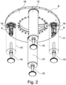
- the lower part has four columns 10, 11, 12 below the bearing device 8, of which Figure 1 due to the sectional view, only three can be seen.
- the columns 10, 11, 12 each have a height-adjustable foot 15 so that the container treatment machine 1 can be aligned with respect to the base by adjusting the lengths of the four feet 15 until the desired alignment of the container treatment machine 1 with respect to the base is achieved.
- Servo motors 4, 6 are arranged in two of the columns 10, 11: a first servo motor 4 in a first column 10 and a second servo motor 6 in a second column 11.
- the servo motors 4, 6 are installed vertically in the columns 10, 11 to save space and each have a drive pinion 5, 7 at their output ends: a first drive pinion 5 is assigned to the first servo motor 4 and a second drive pinion 7 is assigned to the second servo motor 6.
- the servo motors 4, 6 are each firmly connected to the bearing device 8 by means of suitable connecting means known to those skilled in the art.
- the respective motor units of the servo motors 4, 6 are arranged below the annular plate 16 of the bearing device 8 and the respective drive pinions 5, 7 are arranged above this annular plate 16.
- the first servo motor 4 pierces this annular plate 16 in the area of a first opening 13 and the second servo motor 6 in the area of a second opening 14.
- the two drive pinions 5, 7 are arranged in the same plane as the gear ring 9 outside the latter and the drive pinions 5, 7 form tooth connections with the teeth of the gear ring 9 designed as an external gear ring by meshing with each other.
- a planetary gear 19 is arranged, through which the high speeds of the servo motors 4, 6 are adjusted to such an extent that the drive pinions 5, 7 rotate at the speed required to drive the gear ring 9.
- the planetary gears 19 are also in the Figures 2 and 3 without this being discussed separately in the following description.
- Figure 2 which shows the lower, static part of the container treatment machine 1 obliquely from below, all four columns 10, 11, 12 with their height-adjustable feet 15 can be clearly seen.
- the arrangement of the motor units of the servo motors 4, 6 below the annular plate 16 and the fastening of the servo motors 4, 6 to the annular plate 16 can be clearly seen.
- Figure 3 shows the lower, static part of the container treatment machine 1 including the bearing device 8 and the gear ring 9 mounted on the static part, which belongs to the upper, rotating part of the container treatment machine 1, viewed diagonally from above.
- the two drive pinions 5, 7 of the two servo motors 4, 6 can be clearly seen - as well as the motor units of the servo motors 4, 6, which are actually hidden by the ring-shaped plate 16 and the first column 10 or the second column 11.
- the meshing of the drive pinions 5, 7 with the teeth of the The gear ring 9 is shown only schematically, with the teeth of the gear ring 9 and those of the second drive pinion 7 in the region of its engagement with the teeth of the gear ring 9 being omitted.
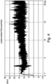
- the servo motor is constantly controlled so that its torque fluctuates greatly, which is reflected in the wild jagged movement of the graph, which runs roughly in a range between 2.5 and 25 Nm.
- the control is such that the servo motor decelerates at each high point and accelerates at each low point; the servo motor is therefore subject to constant accelerations and decelerations.
- a servo motor with a nominal torque of 37 Nm is required, although the average torque is only approximately 15 Nm. This over-dimensioning is also due to the fact that the servo rotor must have a certain inertia in order to be able to counteract the enormous inertia of the rotating gyroscope of the container handling machine.
- a motor in particular a servo motor, can also be provided in at least a third column 12, which drives a drive pinion and the ring gear in a similar manner.
- the at least third motor can then be operated in drive or generator mode as required in order to drive this ring gear together with the other drive pinions and their motors that are in engagement with the ring gear.
- the first servo motor 4 has the first load profile 17 and the second servo motor 6 the second load profile 18. Until the time T, at which the production speed is reached and - as in Figure 4 - approximately 0.5 s after the two servo motors 4, 6 have started up, the torques increase rapidly to a value of approximately 13 Nm each.
- the two servo motors 4, 6 are operated in the same direction during this period and thus complement each other.
- the second servo motor 6 is operated in its generator mode, so that the second load curve 18 assigned to it drops steeply to a value of approximately -5 Nm. Energy is thus recovered by means of the second servo motor 6.
- the first servo motor 4 is used only for the acceleration and the second servo motor 6 only for the deceleration of the gyro 2 of the container treatment machine 1 according to the invention.
- the first servo motor 4 can be described as a drive motor and the second servo motor 6 can be described as a brake motor.
- each drive pinion 5, 7 is assigned its own gear ring 9, wherein the pairings of drive pinion 5; 7 and gear ring 9 can be designed differently, depending on the main function they are intended to fulfill.
- At least one of the motors 4, 6 or their drive pinions 5, 7 is connected to the respective gear ring 9 in a force-transmitting manner via at least one belt, ideally via at least one toothed belt, wherein the other aforementioned aspects are applied in an analogous manner.
Landscapes
- Engineering & Computer Science (AREA)
- Mechanical Engineering (AREA)
- Mixers With Rotating Receptacles And Mixers With Vibration Mechanisms (AREA)
- Connection Of Motors, Electrical Generators, Mechanical Devices, And The Like (AREA)
- Retarders (AREA)
Description
- Die vorliegende Erfindung betrifft eine Behälterbehandlungsmaschine mit einer Antriebsvorrichtung zum rotierenden Antrieb eines Kreisels, an dem die zu behandelnden Behälter aufnehmbar sind. Die Erfindung betrifft auch ein Verfahren zum Betreib der Behälterbehandlungsmaschine.
- Behälterbehandlungsmaschinen werden unter anderem zum industriellen Befüllen, Reinigen und Verschließen von Behältern, wie PET-Flaschen, verwendet. Bei solchen Anlagen wird eine höchstgenaue Übergabe beziehungsweise ein höchstgenauer Transport der Behälter angestrebt.
- Aus der
EP 3 034 421 A1 ist eine Behälterbehandlungsmaschine gemäß dem Oberbegriff des Anspruchs 1 umfassend ein um eine vertikale Achse rotierbares Karussell für die Handhabung von Gegenständen bekannt, das einen Stator und einen Rotor aufweist. Der Rotor hat einen Zahnkranz, der mit Ritzeln von am Stator angebrachten, zueinander beabstandeten Motoren angetrieben wird. Die Motoren können über eine Kontrolleinheit zur Beschleunigung oder Abbremsung des Karussells so geschaltet werden, dass ihre Drehmomente in die gleiche Richtung gerichtet sind, oder bei normalem Betrieb ihre Drehmomente in gegenläufiger Richtung gerichtet sind, wobei die Drehmomente immer auf einer konstanten Differenz gehalten werden. Dadurch ist das Karussell in seinen Einsatzmöglichkeiten eingeschränkt. - Aus der
DE 10 2013 204 461 A1 ist eine Rundläufermaschine mit einem Karussell zur Förderung von Behältern in Behälteraufnahmen und einem Aggregat zur Behandlung und/oder Inspektion der Behälter bekannt geworden. Diese Rundläufermaschine zeichnet sich insbesondere dadurch aus, dass das Karussell mit einem Zahnrad verbunden ist, in das wenigstens zwei Antriebe über Ritzel eingreifen, und wobei eine Motorregelung in einem positionsgeregelten Betrieb des Karussells dazu ausgebildet ist, die Drehmomente der beiden Antriebe derart zu regeln, dass sie entgegengesetzt zueinander auf das Zahnrad wirken. - Antriebsmotoren in Stützstrukturen von Behandlungsanlagen zu integrieren ist beispielsweise aus den Druckschriften
GB 1 188 888 A EP 1 714 939 A1 ,DE 20 2005 002469 U1 oderDE 20 2005 002470 U1 bekannt. - Aus der
DE 10 2012 000 881 A1 ist beispielsweise bereits eine Behälterbehandlungsmaschine bekannt, die zum Verschließen von Behältern verwendet wird. Diese Behälterbehandlungsmaschine verfügt über einen umlaufenden Kreisel zur Aufnahme und Behandlung der Behälter, eine ortsfeste sowie frei von Elementen zur mechanischen Leistungsübertragung ausgebildeten Zentralsäule zur Lagerung des Kreisels. Außenumfangsseitig ist am Kreisel ein Antrieb angebracht, der über ein Antriebsritzel eines Antriebsmotors in eine Außenverzahnung des Kreisels eingreift. Der Antriebsmotor ist als ein hinsichtlich des Nenndrehmoments überdimensionierter Servomotor ausgebildet. Der enorme Leistungsüberschuss des Servomotors ist für die Regelung der Anlage notwendig, um einen ausreichenden Synchronlauf zu erreichen. Der Servomotor ist dauerhaften Beschleunigungen und Verzögerungen ausgesetzt. Durch die ständige Drehfeldänderung in der Wicklung des Servomotors entsteht eine Induktionsspannung, die zur Erwärmung des Servomotors führt; der Leistungsüberschuss des Motors wird somit in Wärme umgewandelt. Um der enormen Trägheit des rotierenden Kreisels entgegen wirken zu können, muss der Servo-Läufer/Rotor eine gewisse Eigenträgheit aufbringen. Dies führt ebenfalls zu der oben angeführten Überdimensionierung des Servomotors. - Es ist die Aufgabe der vorliegenden Erfindung, die genannten Nachteile zu vermeiden.
- Diese Aufgabe wird erfindungsgemäß durch eine Behälterbehandungsvorrichtung mit einer Antriebsvorrichtung mit den Merkmalen des Patentanspruchs 1 gelöst. Danach ist vorgesehen, dass zwei Antriebsritzel der beiden Motoren, beziehungsweise mit welchen die Motoren verbunden sind, jeweils mit der Verzahnung des Zahnkranzes des Kreisels kämmen - alternativ kann auch eine andere Verbindung zwischen Motoren beziehungsweise Antriebsritzeln auf der einen Seite und Zahnkranz auf der anderen Seite ausgebildet sein, beispielsweise ein zwischengeschalteter Zahnriemen. Die beiden Antriebsritzel wirken dabei an in Umfangsrichtung unterschiedlichen Stellen des Zahnkranzes mit diesem zusammen. Dadurch ist es möglich, geringer dimensionierte Motoren zu verwenden, als dies beim Stand der Technik mit einem Motor der Fall war; diese zwei Motoren können eine deutlich geringere Antriebsleistung aufweisen. Durch ein intelligentes Antriebskonzept kann dabei die Antriebsleistung und die Motorgröße halbiert werden. Außerdem kann die Behälterbehandlungsmaschine absolut spielfrei betrieben werden, ohne dass der Einsatz eines spielarmen Getriebes notwendig ist. Mittels der Erfindung sind Verschleiß und Lagerschäden messbar und das Nichtvorhandensein derselben können überwacht werden. Dadurch, dass der erste Motor in einer ersten Säule der Lagervorrichtung und der zweite Motor in einer zweiten Säule der Lagervorrichtung angeordnet ist, kann ein einfacher und raumsparender Aufbau der Behälterbehandlungsmaschine erreicht werden.
- Eine vorteilhafte Weiterbildung der Erfindung sieht vor, dass die Motoren Servomotoren, Gleichstrommotoren, Synchronmotoren, Asynchronmotoren oder Torque-Motoren sind. Bevorzugt ist jeder der beiden Motoren ein Servomotor. Unter einem Servomotor wird ein einfacher Synchron- oder Asynchronmotor verstanden, der mit einem Sensor (Drehimpulsgeber) ausgestattet ist. Beispiele für Kombinationen verschiedener Motortypen sind: ein Servomotor als Bremsmotor und ein Gleichstrommotor als Antriebsmotor; ein Servomotor als Bremsmotor und ein Synchron- oder Asynchronmotor als Antriebsmotor; ein Servomotor als Bremsmotor und ein Torque-Motor als Antriebsmotor (wobei diese Kombination allerdings teuer ist). Unter einem Torque-Motor wird ein Servomotor mit vielen Polpaaren verstanden. Je mehr Polpaare (Wicklungen) man in solch einem Antrieb einsetzt, umso größer und schwerer wird dieser Antrieb. Theoretisch ist auch die Verwendung von zwei Torque-Motoren möglich; praktisch wird eine solche Variante jedoch kaum eingesetzt werden, da die Torque-Motoren in einem niedrigen Drehzahlbereich arbeiten und sich auch einzeln sehr gut regeln lassen.
- Eine weitere vorteilhafte Weiterbildung der Erfindung sieht vor, dass die beiden Ritzel der Motoren auf einer Geraden, die einen Durchmesser der Verzahnung umfasst, angeordnet sind. Dadurch kann eine optimale Ausnutzung der Antriebsleistung der Motoren erzielt werden.
- Eine Ausformung der Erfindung sieht vor, dass der Zahnkranz ein Außenzahnkranz ist.
- Eine weitere vorteilhafte Weiterbildung der Erfindung sieht vor, dass es sich bei den Zahnverbindungen zwischen erstem Antriebsritzel und Verzahnung sowie zwischen zweitem Antriebsritzel und Verzahnung jeweils um geradverzahnte Kugeldrehverbindungen handelt. Dadurch ist keine hohe Verzahnungs-Qualität notwendig, um ausreichende Ergebnisse zu bekommen.
- Eine weitere vorteilhafte Weiterbildung der Erfindung sieht vor, dass mindestens einer der Motoren oder deren Antriebsritzel über einen Zahnriemen mit dem Zahnkranz kraftübertragend verbunden ist. Dadurch kann mit einfachen Mitteln eine gute Kraftübertragung stattfinden. Insbesondere kann zwischen mindestens einem der Motoren und dem zugeordneten Antriebsritzeln ein Übergangsgetriebe, wie bspw. ein Planetengetriebe angeordnet sein.
- Eine weitere vorteilhafte Ausführungsform der Behälterbehandlungsmaschine sieht vor, dass der erste Motor und/oder der zweite Motor eine Gruppe von zwei oder mehr Motoren darstellt, so dass durch drei oder mehr Motoren gemeinsam die rotierende Bewegung des Zahnkranzes und des Kreisels erfolgt.
- Dabei sind die mindestens drei Motoren idealerweise unabhängig voneinander steuer- und/oder regelbar. Zusätzlich kann vorteilhafterweise vorgesehen werden, dass mindestens drei oder alle Motoren in den Säulen aufgenommen sind.
- Des Weiteren wird die Aufgabe erfindungsgemäß durch ein Verfahren zum Betrieb einer Behälterbehandlungsmaschine mit den Merkmalen des Patentanspruchs 9 gelöst. Dadurch, dass bis zum Erreichen der Produktionsgeschwindigkeit bei Beschleunigung und Verzögerung des Kreisels die beiden Motoren gleichsinnig betrieben werden, steht permanent - bis die notwendige Produktionsgeschwindigkeit erreicht wird - die doppelte Antriebsleistung zur Verfügung. Dadurch, dass nach Erreichen der Produktionsgeschwindigkeit der zweite Motor in seinem Generatorbetrieb betrieben wird, kann dauerhaft eine Energierückgewinnung durch den zweiten Motor erreicht werden, was zur Reduktion der benötigten elektrischen Energie führt.
- Eine vorteilhafte Weiterbildung der erfindungsgemäßen Verfahren sieht vor, dass während des Regelbetriebs der erste Motor nur für die Beschleunigung und der zweite Motor nur für die Verzögerung des Kreisels verwendet werden, wird erreicht, dass die beiden Motoren gegenüber einer ständigen Umpolung geschont werden. Außerdem wird eine erhöhte Wärmeproduktion der Motoren durch die Vermeidung ständiger Drehfeldänderungen vermieden.
- Weitere Einzelheiten und Vorteile der Erfindung werden anhand eines in den Zeichnungen dargestellten Ausführungsbeispiels näher erläutert.
- Es zeigen:
- Figur 1
- eine schematische Schnittdarstellung einer erfindungsgemäßen Behälterbehandlungsmaschine,
- Figur 2
- eine schematische Darstellung eines Teils der Behälterbehandlungsmaschine der
Figur 1 , schräg von unten gesehen, - Figur 3
- eine schematische Darstellung des Teils der Behälterbehandlungsmaschine aus
Figur 2 , schräg von oben gesehen, - Figur 4
- Beispiel eines Lastenverlaufs eines Servoantriebs gemäß dem Stand der Technik und
- Figur 5
- Beispiel eines Lastenverlaufs der beiden Servomotoren gemäß der Erfindung.
-
Figur 1 zeigt eine schematische Schnittdarstellung in der Seitenansicht eines Ausführungsbeispiels einer erfindungsgemäßen Behälterbehandlungsmaschine 1 mit einer erfindungsgemäßen Antriebsvorrichtung. Dort sind nur die Teile dargestellt, die für die erfindungsgemäße Antriebsvorrichtung und die erfindungsgemäßen Verfahren relevant sind. Die weiteren Teile der Behälterbehandlungsmaschine 1 sind dem Fachmann aus dem Stand der Technik bekannt und werden im Folgenden nicht näher erläutert. Im Folgenden werden als Motoren 4, 6 Servomotoren - dies ist die bevorzugte Ausgestaltung - beschrieben: der erster Motor 4 wird im Folgenden als erster Servomotor 4 und der zweite Motor 6 wird in Folgenden als zweiter Servomotor 6 bezeichnet. Mit den anderen oben genannten Elektromotorentypen ist das erfindungsgemäße Ausführungsbeispiel genauso realisierbar. - Die Behälterbehandlungsmaschine 1 weist einen statischen unteren Teil auf, der gegenüber einer (nicht dargestellten) Standfläche unbeweglich ist, und einen um eine Rotationsachse R rotierenden oberen Teil.
- Der rotierende obere Teil weist einen Kreisel 2 auf, an dem Behälter 3 angebracht werden können und der diese bei seiner Rotationsbewegung mitnimmt. Am unteren Ende des Kreisels 3 ist ein kreisförmiger Zahnkranz 9 fest mit diesem verbunden und konzentrisch zur Rotationsachse R angeordnet.
- Der statische untere Teil weist in seinem oberen Endbereich eine horizontal verlaufende Lagervorrichtung 8 auf. In der Lagervorrichtung 8 ist der Zahnkranz 9 des oberen Teils rotierbar gelagert. Die Lagervorrichtung 8 weist eine horizontal verlaufende, ringförmige Platte 16 mit einer zentralen Öffnung auf. Derartige Lagerungen sind dem Fachmann gut bekannt, so dass auf deren nähere Ausgestaltung hier nicht eingegangen wird.
- Der untere Teil weist unterhalb der Lagervorrichtung 8 vier Säulen 10, 11, 12 auf, von denen in
Figur 1 aufgrund der Schnittdarstellung nur drei zu sehen sind. An ihren unteren Enden weisen die Säulen 10, 11, 12 jeweils einen höhenverstellbaren Fuß 15 auf, so dass die Behälterbehandlungsmaschine 1 gegenüber der Standfläche ausgerichtet werden kann, indem die Längen der vier Füße 15 so angepasst werden, bis die gewünschte Ausrichtung der Behälterbehandlungsmaschine 1 gegenüber der Standfläche erreicht ist. - In zweien der Säulen 10, 11 sind Servomotoren 4, 6 angeordnet: in einer ersten Säule 10 ein erster Servomotor 4 und in einer zweiten Säule 11 ein zweiter Servomotor 6. Die Servomotoren 4, 6 sind zur Platzersparnis vertikal in den Säulen 10, 11 verbaut und weisen an ihren abtriebsseitigen Enden jeweils ein Antriebsritzel 5, 7 auf: ein erstes Antriebsritzel 5 ist dem ersten Servomotor 4 und ein zweites Antriebsritzel 7 ist dem zweiten Servomotor 6 zugeordnet. Die Servomotoren 4, 6 sind jeweils mittels geeigneter, dem Fachmann bekannter Verbindungsmittel fest mit der Lagervorrichtung 8 verbunden. Dabei sind die jeweiligen Motoreinheiten der Servomotoren 4, 6 unterhalb der ringförmigen Platte 16 der Lagervorrichtung 8 und die jeweiligen Antriebsritzel 5, 7 oberhalb dieser ringförmigen Platte 16 angeordnet. Um dies realisieren zu können, durchstößt der erste Servomotor 4 diese ringförmige Platte 16 im Bereich einer ersten Durchbrechung 13 und der zweite Servomotor 6 im Bereich einer zweiten Durchbrechung 14.
- Die beiden Antriebsritzel 5, 7 sind in derselben Ebene wie der Zahnkranz 9 außerhalb desselben angeordnet und die Antriebsritzel 5, 7 bilden mit der Verzahnung des als Außenzahnkranz ausgebildeten Zahnkranzes 9 Zahnverbindungen, indem sie jeweils miteinander kämmen.
- Zwischen den Servomotoren 4, 6 und den zugeordneten Antriebsritzeln 5, 7 ist jeweils ein Planetengetriebe 19 angeordnet, durch das die hohen Drehzahlen der Servomotoren 4, 6 so weit angepasst werden, dass die Antriebsritzel 5, 7 mit der Drehzahl rotieren, die für den Antrieb des Zahnkranzes 9 erforderlich ist. Die Planetengetriebe 19 sind auch in den
Figuren 2 und3 dargestellt, ohne dass in der folgenden Beschreibung hierzu noch einmal separat darauf eingegangen wird. - In
Figur 2 , die den unteren, statischen Teil der Behälterbehandlungsmaschine 1 schräg von unten zeigt, sind gut alle vier Säulen 10, 11, 12 mit ihren höhenverstellbaren Füßen 15 zu erkennen. Außerdem ist gut die Anordnung der Motoreinheiten der Servomotoren 4, 6 unterhalb der ringförmigen Platte 16 und die Befestigung der Servomotoren 4, 6 an der ringförmigen Platte 16 zu erkennen. -
Figur 3 zeigt den unteren, statischen Teil der Behälterbehandlungsmaschine 1 samt Lagervorrichtung 8 und den auf dem statischen Teil montierte Zahnkranz 9, der zum oberen, rotierenden Teil der Behälterbehandlungsmaschine 1 gehört, schräg von oben. Es sind gut die beiden Antriebsritzel 5, 7 der beiden Servomotoren 4, 6 zu erkennen - ebenso die eigentlich von der ringförmigen Platte 16 und der ersten Säule 10 beziehungsweise der zweiten Säule 11 verdeckten Motoreinheiten der Servomotoren 4, 6. Das Kämmen der Antriebsritzel 5, 7 mit der Verzahnung des Zahnkranzes 9 ist nur schematisch dargestellt, wobei die Verzahnung des Zahnkranzes 9 und diejenige des zweiten Antriebsritzels 7 im Bereich seines Eingriffs in die Verzahnung des Zahnkranzes 9 weggelassen wurden. - Außerdem ist in
Figur 3 gut zu erkennen, dass die beiden Antriebsritzel 5, 7 der Servomotoren 4, 6 so zu dem Zahnkranz 9 angeordnet sind, dass sie auf einer Geraden angeordnete sind, die einen Durchmesser des Zahnkranzes 9 umfasst. Sie sind somit weitest möglich voneinander entfernt am Zahnkranz 9 angeordnet. - Im Folgenden wird die Funktionsweise der erfindungsgemäßen Antriebsvorrichtung nähe erläutert. Hierzu dient ein Vergleich der Lastenverläufe eines Servoantriebs gemäß dem Stand der Technik (siehe
Figur 4 ) mit denjenigen der beiden Servomotoren 4, 6 gemäß dem erfindungsgemäßen Ausführungsbeispiel (sieheFigur 5 ):
Der Lastenverlauf des einzigen Servomotors gemäß dem Stand der Technik ist inFigur 4 dargestellt. Bis zum Zeitpunkt T, zu dem die Produktionsgeschwindigkeit erreicht wird - im dargestellten Beispiel ist das ungefähr 0,5 s nach Anlaufen des Servomotors der Fall -, steigt das Drehmoment rapide bis auf einen Wert von ungefähr 13 Nm an. Danach ist die Produktionsgeschwindigkeit erreicht und die Behälterbehandlungsmaschine muss so geregelt werden, dass die Vorgaben für die Produktionsgeschwindigkeit eingehalten werden. Hierfür wird der Servomotor ständig geregelt, so dass sein Drehmoment stark schwankt, was sich in der wilden Zackenbewegung des Graphen widerspiegelt, der ungefähr in einem Bereich zwischen 2,5 und 25 Nm verläuft. Die Regelung erfolgt so, dass bei jedem Hochpunkt eine Verzögerung und bei jedem Tiefpunkt eine Beschleunigung des Servomotors eingeleitet wird; der Servomotor ist somit dauerhaften Beschleunigungen und Verzögerungen unterworfen. Es wird ein Servomotor mit einem Nenndrehmoment von 37 Nm benötigt, obwohl das mittlere Drehmoment nur bei ca. 15 Nm liegt. Diese Überdimensionierung liegt auch daran, dass der Servo-Läufer eine gewisse Eigenträgheit aufweisen muss, um der enormen Trägheit des rotierenden Kreisels der Behälterbehandlungsmaschine entgegenwirken zu können. - Ganz allgemein kann in einer nicht dargestellten Variante mindestens in einer dritten Säule 12 ebenfalls ein Motor, insbesondere ein Servomotor, vorgesehen sein, der analog ein Antriebsritzel und den Zahnkranz antreibt. Der mindestens dritte Motor kann dann bedarfsweise im Antriebs- oder im Generatormodus betrieben werden, um gemeinsam mit den sonstigen mit dem Zahnkranz im Eingriff befindlichen Antriebsritzeln und deren Motoren diesen Zahnkranz anzutreiben.
- Im Vergleich zu dem Diagramm der
Figur 4 zeigt dieFigur 5 die Lastenverläufe 17, 18 der beiden Servomotoren 4, 6 des erfindungsgemäßen Ausführungsbeispiels derFiguren 1 bis 3 . - Der erste Servomotor 4 weist den ersten Lastenverlauf 17 und der zweite Servomotor 6 den zweiten Lastenverlauf 18 auf. Bis zum Zeitpunkt T, zu dem die Produktionsgeschwindigkeit erreicht wird und - wie in
Figur 4 - ungefähr 0,5 s nach Anlaufen der beiden Servomotoren 4, 6 erreicht wird, steigen die Drehmomente rapide bis auf einen Wert von ungefähr jeweils 13 Nm an. Die beiden Servomotoren 4, 6 werden während dieses Zeitraumes gleichsinnig betrieben und ergänzen sich som it. - Nachdem die Produktionsgeschwindigkeit zum Zeitpunkt T erreicht wurde, wird der zweite Servomotor 6 in seinem Generatorbetrieb betrieben, so dass der ihm zugeordnete zweite Lastenverlauf 18 steil bis auf einen Wert von ungefähr -5 Nm abfällt. Mittels des zweiten Servomotors 6 wird somit Energie zurückgewonnen. Der erste Lastenverlauf 17, der dem ersten Servomotor 4 zugeordnet ist, schwingt dagegen leicht zwischen Werten von ungefähr 10 Nm und 14 Nm, ohne dass die aus dem Stand der Technik (siehe
Figur 4 ) bekannten großen Ausschläge vorliegen. - Während des sich an den Zeitpunkt T anschließenden Regelbetriebs wird der erste Servomotor 4 nur für die Beschleunigung und der zweite Servomotor 6 nur für die Verzögerung des Kreisels 2 der erfindungsgemäßen Behälterbehandlungsmaschine 1 eingesetzt. Dies führt gemäß dem zweiten Lastenverlauf 18 dazu, dass sich das Drehmoment des zweiten Servomotors 6 ungefähr zwischen -6,5 Nm und -2 Nm bewegt. Weder der erste Lastenverlauf 17 noch der zweite Lastenverlauf 18 weisen die enormen Ausschläge auf, die der Lastenverlauf beim Stand der Technik gemäß
Figur 4 zeigt. Es ist somit möglich, bei der erfindungsgemäßen Ausgestaltung Servomotoren 4, 6 mit deutlich niedrigem Nenndrehmoment zu verwenden - bei ansonsten gleichen Bedingungen -, die im Bereich von ungefähr 15 Nm liegen. - Der erste Servomotor 4 kann quasi als Antriebsmotor und der zweite Servomotor 6 kann quasi als Bremsmotor bezeichnet werden.
- In einer alternativen, nicht gezeigten Ausführungsvariante kann vorgesehen werden, dass jedem Antriebsritzel 5, 7 ein eigener Zahnkranz 9 zugeordnet ist, wobei die Paarungen aus Antriebsritzel 5; 7 und Zahnkranz 9 unterschiedlich ausgeführt sein können, abhängig von der Hauptfunktion, die sie erfüllen sollen.
- In einer alternativen, nicht dargestellte Ausführungsvariante der Vorrichtung und des Verfahrens ist mindestens einer der Motoren 4, 6 bzw. deren Antriebritzel 5, 7 über mindestens einen Riemen, idealerweise über mindestens einen Zahnriemen, kraftübertragend mit dem jeweiligen Zahnkranz 9 verbunden, wobei die sonstigen vorgenannten Aspekte in analoger Weise zur Anwendung kommen.
-
- 1
- Behälterbehandlungsmaschine
- 2
- Kreisel
- 3
- Behälter
- 4
- erster (Servo-)Motor
- 5
- erstes Antriebsritzel
- 6
- zweiter (Servo-)Motor
- 7
- zweites Antriebsritzel
- 8
- Lagervorrichtung
- 9
- Zahnkranz
- 10
- erste Säule
- 11
- zweite Säule
- 12
- weitere Säule
- 13
- erste Durchbrechung
- 14
- zweite Durchbrechung
- 15
- Fuß
- 16
- ringförmige Platte
- 17
- erster Lastenverlauf
- 18
- zweiter Lastenverlauf
- 19
- Planetengetriebe
- R
- Rotationsachse
- T
- Zeitpunkt des Erreichens der Produktionsgeschwindigkeit
Claims (10)
- Behälterbehandlungsmaschine (1) umfassend eine Antriebsvorrichtung, welche einen ersten Motor (4) und einen zweiten Motor (6) aufweist,wobei der erste Motor (4) ein erstes Antriebsritzel (5) und der zweite Motor (6) ein zweites Antriebsritzel (7) aufweisen oder hiermit kraftübertragend verbunden sind,wobei die beiden Motoren (4, 6) ortsfest zu einer Lagervorrichtung (8) angeordnet sind,wobei in der Lagervorrichtung (8) ein Zahnkranz (9) mit einer kreisförmigen Verzahnung, der Teil eines Kreisels (2) ist, an dem Behälter (3) aufnehmbar sind, rotierbar um eine Rotationsachse (R) gelagert ist,wobei jedes der beiden Antriebsritzel (5, 7) der Motoren (4, 6) mit der Verzahnung des Zahnkranzes (9) des Kreisels (2) kämmt oder eine andere Verbindung zwischen den Antriebsritzeln (5, 7) der Motoren (4, 6) und dem Zahnkranz (9) des Kreisels (2) ausgebildet ist unddie beiden Antriebsritzel (5, 7) der Motoren (4, 6) in Umfangsrichtung der Verzahnung zueinander beabstandet angeordnet sind,dadurch gekennzeichnet, dassder erste Motor (4) in einer ersten Säule (10) der Lagervorrichtung (8) und der zweite Motor (6) in einer zweiten Säule (11) der Lagervorrichtung (8) angeordnet ist.
- Behälterbehandlungsmaschine (1) nach Patentanspruch 1, wobei die Motoren (4, 6) Servomotoren, Gleichstrommotoren, Synchronmotoren, Asynchronmotoren oder Torque-Motoren sind.
- Behälterbehandlungsmaschine (1) nach einem der vorstehenden Patentansprüche, wobei die beiden Antriebsritzel (5, 7) der Motoren (4, 6) auf einer Geraden, die einen Durchmesser des Zahnkranzes (9) umfasst, angeordnet sind.
- Behälterbehandlungsmaschine (1) nach einem der vorstehenden Patentansprüche, wobei es sich bei den Zahnverbindungen zwischen erstem Antriebsritzel (5) und Verzahnung sowie zwischen zweitem Antriebsritzel (7) und Verzahnung jeweils um geradverzahnte Kugeldrehverbindungen handelt.
- Behälterbehandlungsmaschine (1) nach einem der vorstehenden Patentansprüche, wobei mindestens einer der Motoren (4, 6) oder deren Antriebsritzel (5, 7) über einen Zahnriemen mit dem Zahnkranz (9) kraftübertragend verbunden ist.
- Behälterbehandlungsmaschine (1) nach einem der vorstehenden Patentansprüche, wobei mindestens zwischen einem der Motoren (4, 6) und den zugeordneten Antriebsritzeln (5, 7) ein Planetengetriebe (19) angeordnet ist.
- Behälterbehandlungsmaschine (1) nach einem der vorstehenden Patentansprüche, wobei der erste Motor (4) und/oder der zweite Motor (6) eine Gruppe von zwei oder mehr Motoren darstellt.
- Behälterbehandlungsmaschine (1) nach Anspruch 7, wobei mindestens drei Motoren unabhängig voneinander steuer- und/oder regelbar sind.
- Verfahren zum Betrieb einer Behälterbehandlungsmaschine (1), wobei die Behälterbehandlungsmaschine (1) nach einem der vorangehenden Ansprüche 1 bis 8 ausgebildet ist, wobei vom Anlaufen bis zum Erreichen der Produktionsgeschwindigkeit bei Beschleunigung und Verzögerung des Kreisels (2) die beiden Motoren (4, 6) gleichsinnig betrieben werden und wobei nach Erreichen der Produktionsgeschwindigkeit der zweite Motor (6) in seinem Generatorbetrieb betrieben wird.
- Verfahren nach Patentanspruch 9, wobei während des Regelbetriebs der erste Motor (4) nur für die Beschleunigung und der zweite Motor (6) nur für die Verzögerung des Kreisels (2) verwendet werden.
Applications Claiming Priority (2)
| Application Number | Priority Date | Filing Date | Title |
|---|---|---|---|
| DE102017112202.8A DE102017112202A1 (de) | 2017-06-02 | 2017-06-02 | Antriebsvorrichtung für Behälterbehandlungsmaschine sowie Verfahren zum Betrieb einer Behälterbehandlungsmaschine |
| PCT/EP2018/064206 WO2018220026A1 (de) | 2017-06-02 | 2018-05-30 | Behälterbehandlungsmaschine sowie verfahren zum betrieb einer behälterbehandlungsmaschine |
Publications (2)
| Publication Number | Publication Date |
|---|---|
| EP3630628A1 EP3630628A1 (de) | 2020-04-08 |
| EP3630628B1 true EP3630628B1 (de) | 2024-11-20 |
Family
ID=62486584
Family Applications (1)
| Application Number | Title | Priority Date | Filing Date |
|---|---|---|---|
| EP18728369.2A Active EP3630628B1 (de) | 2017-06-02 | 2018-05-30 | Behälterbehandlungsmaschine sowie verfahren zum betrieb einer behälterbehandlungsmaschine |
Country Status (5)
| Country | Link |
|---|---|
| US (1) | US11046566B2 (de) |
| EP (1) | EP3630628B1 (de) |
| CN (1) | CN110691740B (de) |
| DE (1) | DE102017112202A1 (de) |
| WO (1) | WO2018220026A1 (de) |
Families Citing this family (1)
| Publication number | Priority date | Publication date | Assignee | Title |
|---|---|---|---|---|
| WO2017182839A1 (en) * | 2016-04-18 | 2017-10-26 | Metotecna Sagl | Transfer machine with a rotary table |
Family Cites Families (19)
| Publication number | Priority date | Publication date | Assignee | Title |
|---|---|---|---|---|
| US2827998A (en) * | 1954-11-05 | 1958-03-25 | Crown Cork & Seal Co | Container feeding mechanism |
| GB1188888A (en) | 1967-06-20 | 1970-04-22 | Simonazzi Spa A & L | Machine for Automatic Bottle Filling. |
| US4997330A (en) * | 1989-06-27 | 1991-03-05 | Charles Packaging Corporation | Article handling and weighing apparatus |
| US5800112A (en) * | 1997-10-16 | 1998-09-01 | Ems-Tech Inc. | Loading spout hoist mechanism |
| US7997048B2 (en) * | 2004-10-09 | 2011-08-16 | Khs Maschinen- Und Anlagenbau Ag | Container filling plant, such as a beverage bottling plant, for filling containers with a liquid beverage and for closing filled containers |
| DE202005002469U1 (de) | 2005-02-16 | 2005-05-25 | Krones Ag | Vortischsystem |
| DE202005002470U1 (de) | 2005-02-16 | 2005-11-10 | Krones Ag | Transportsystem für Behälter-Behandlungsmaschinen |
| ITBO20050254A1 (it) | 2005-04-19 | 2005-07-19 | Azionaria Costruzioni Acma Spa | Apparato per il trattamento di contenitori con prodotti liquidi o in polvere |
| US7832546B2 (en) * | 2006-04-28 | 2010-11-16 | Fabrizio Preti | Star wheel |
| DE102008010895A1 (de) | 2008-02-23 | 2009-08-27 | Krones Ag | Fördereinrichtung |
| DE102008001285A1 (de) * | 2008-04-21 | 2009-10-22 | Robert Bosch Gmbh | Vorrichtung zum Transportieren eines Behälters |
| CN201880067U (zh) * | 2010-11-30 | 2011-06-29 | 深圳市怀德科技发展有限公司 | 用于消毒的给药机构 |
| DE102012000881A1 (de) | 2011-12-14 | 2013-06-20 | Khs Gmbh | Behandlungsmaschine für Behälter |
| DE102013204461A1 (de) * | 2013-03-14 | 2014-09-18 | Krones Ag | Rundläufermaschine mit einem Karussell und Verfahren für eine Rundläufermaschine |
| US9145259B2 (en) * | 2013-04-09 | 2015-09-29 | T&T Consulting And Engineering, Inc. | Column drive for spiral conveyors |
| DE102013104082B4 (de) * | 2013-04-23 | 2017-02-02 | Khs Gmbh | Transportvorrichtung für Behälter |
| US9745182B2 (en) * | 2013-08-21 | 2017-08-29 | Fluid Management Operations Llc | Actuating system and nozzles for liquid dispensers |
| US9181043B1 (en) * | 2014-06-03 | 2015-11-10 | The Procter & Gamble Company | Elevation change system for a rotary device |
| EP3034421A1 (de) | 2014-12-15 | 2016-06-22 | Sidel Participations, S.A.S. | Karussell für eine Artikelhandhabungsmaschine und zugehöriges Verfahren zum Antrieb beim Drehen |
-
2017
- 2017-06-02 DE DE102017112202.8A patent/DE102017112202A1/de not_active Withdrawn
-
2018
- 2018-05-30 CN CN201880035009.2A patent/CN110691740B/zh active Active
- 2018-05-30 EP EP18728369.2A patent/EP3630628B1/de active Active
- 2018-05-30 WO PCT/EP2018/064206 patent/WO2018220026A1/de not_active Ceased
- 2018-05-30 US US16/617,833 patent/US11046566B2/en active Active
Also Published As
| Publication number | Publication date |
|---|---|
| US11046566B2 (en) | 2021-06-29 |
| US20200148525A1 (en) | 2020-05-14 |
| CN110691740A (zh) | 2020-01-14 |
| EP3630628A1 (de) | 2020-04-08 |
| WO2018220026A1 (de) | 2018-12-06 |
| DE102017112202A1 (de) | 2018-12-06 |
| CN110691740B (zh) | 2022-07-26 |
Similar Documents
| Publication | Publication Date | Title |
|---|---|---|
| EP1286048B1 (de) | Einrichtung zum Verstellen des Rotorblattes eines Rotors einer Windkraftanlage | |
| DE10352016B3 (de) | Verschließmaschine zum Verschließen von Gefäßen | |
| EP2255923B1 (de) | Rundschalttisch | |
| EP2059471A1 (de) | Sektionaler antrieb eines drehkranzes für eine abfüllanlage | |
| DE102007057857A1 (de) | Vorrichtung zum Verschließen von Behältern | |
| EP3630670B1 (de) | Verschliessmaschine umlaufender bauart | |
| DE9116345U1 (de) | Vorrichtung zur Schwingungserregung | |
| DE102009032231B4 (de) | Presse | |
| DE102012000881A1 (de) | Behandlungsmaschine für Behälter | |
| DE2229525A1 (de) | Verfahren und vorrichtung zum ausgleichen der bearbeitungsdistanzen zwischen einem werkzeug und einem werkstueck bei der funkenerosiven oder elektrochemischen bearbeitung | |
| EP3630628B1 (de) | Behälterbehandlungsmaschine sowie verfahren zum betrieb einer behälterbehandlungsmaschine | |
| EP3104503B1 (de) | Spielfreier drehantrieb | |
| EP1516699B1 (de) | Fertigung- und/oder Montagevorrichtung | |
| DE2638688C2 (de) | Vorrichtung zum Auffädeln und gleichzeitigen Drehen der Muttern mehrerer Schraubenbolzen | |
| DE1573509B1 (de) | Vorrichtung zum Ausgleichen der Unwucht an umlaufenden Koerpern | |
| DE60120022T2 (de) | Elektrisch betriebene Vorrichtung für einen Greifer | |
| WO2012163449A1 (de) | Behandlungsmaschine für behälter | |
| EP3491238B1 (de) | Maschinenhaus für eine windenergieanlage sowie verfahren | |
| DE2437398A1 (de) | Dynamische auswucht-vorrichtung zum ausgleich von rotierenden maschinenteilen, insbesondere schleifscheiben | |
| DE102009004699B4 (de) | Drehtisch mit motorischem Antrieb | |
| EP1728574A1 (de) | Spannvorrichtung einer Werkzeugmaschine | |
| WO2019234179A1 (de) | Windenergieanlage | |
| DE10147046A1 (de) | Antriebssystem für ein Walzwerk | |
| DE69320562T2 (de) | Vorrichtung zur Herstellung von Kugeln von Teig oder ähnlichem Werkstoff | |
| DE3034627A1 (de) | Schrittantriebs-vorrichtung |
Legal Events
| Date | Code | Title | Description |
|---|---|---|---|
| STAA | Information on the status of an ep patent application or granted ep patent |
Free format text: STATUS: UNKNOWN |
|
| STAA | Information on the status of an ep patent application or granted ep patent |
Free format text: STATUS: THE INTERNATIONAL PUBLICATION HAS BEEN MADE |
|
| PUAI | Public reference made under article 153(3) epc to a published international application that has entered the european phase |
Free format text: ORIGINAL CODE: 0009012 |
|
| STAA | Information on the status of an ep patent application or granted ep patent |
Free format text: STATUS: REQUEST FOR EXAMINATION WAS MADE |
|
| 17P | Request for examination filed |
Effective date: 20200102 |
|
| AK | Designated contracting states |
Kind code of ref document: A1 Designated state(s): AL AT BE BG CH CY CZ DE DK EE ES FI FR GB GR HR HU IE IS IT LI LT LU LV MC MK MT NL NO PL PT RO RS SE SI SK SM TR |
|
| AX | Request for extension of the european patent |
Extension state: BA ME |
|
| DAV | Request for validation of the european patent (deleted) | ||
| DAX | Request for extension of the european patent (deleted) | ||
| STAA | Information on the status of an ep patent application or granted ep patent |
Free format text: STATUS: EXAMINATION IS IN PROGRESS |
|
| 17Q | First examination report despatched |
Effective date: 20220718 |
|
| GRAP | Despatch of communication of intention to grant a patent |
Free format text: ORIGINAL CODE: EPIDOSNIGR1 |
|
| STAA | Information on the status of an ep patent application or granted ep patent |
Free format text: STATUS: GRANT OF PATENT IS INTENDED |
|
| INTG | Intention to grant announced |
Effective date: 20240625 |
|
| GRAS | Grant fee paid |
Free format text: ORIGINAL CODE: EPIDOSNIGR3 |
|
| GRAA | (expected) grant |
Free format text: ORIGINAL CODE: 0009210 |
|
| STAA | Information on the status of an ep patent application or granted ep patent |
Free format text: STATUS: THE PATENT HAS BEEN GRANTED |
|
| AK | Designated contracting states |
Kind code of ref document: B1 Designated state(s): AL AT BE BG CH CY CZ DE DK EE ES FI FR GB GR HR HU IE IS IT LI LT LU LV MC MK MT NL NO PL PT RO RS SE SI SK SM TR |
|
| REG | Reference to a national code |
Ref country code: GB Ref legal event code: FG4D Free format text: NOT ENGLISH |
|
| REG | Reference to a national code |
Ref country code: CH Ref legal event code: EP |
|
| REG | Reference to a national code |
Ref country code: DE Ref legal event code: R096 Ref document number: 502018015340 Country of ref document: DE |
|
| REG | Reference to a national code |
Ref country code: IE Ref legal event code: FG4D Free format text: LANGUAGE OF EP DOCUMENT: GERMAN |
|
| REG | Reference to a national code |
Ref country code: LT Ref legal event code: MG9D |
|
| REG | Reference to a national code |
Ref country code: NL Ref legal event code: MP Effective date: 20241120 |
|
| PG25 | Lapsed in a contracting state [announced via postgrant information from national office to epo] |
Ref country code: HR Free format text: LAPSE BECAUSE OF FAILURE TO SUBMIT A TRANSLATION OF THE DESCRIPTION OR TO PAY THE FEE WITHIN THE PRESCRIBED TIME-LIMIT Effective date: 20241120 Ref country code: IS Free format text: LAPSE BECAUSE OF FAILURE TO SUBMIT A TRANSLATION OF THE DESCRIPTION OR TO PAY THE FEE WITHIN THE PRESCRIBED TIME-LIMIT Effective date: 20250320 Ref country code: PT Free format text: LAPSE BECAUSE OF FAILURE TO SUBMIT A TRANSLATION OF THE DESCRIPTION OR TO PAY THE FEE WITHIN THE PRESCRIBED TIME-LIMIT Effective date: 20250320 |
|
| PG25 | Lapsed in a contracting state [announced via postgrant information from national office to epo] |
Ref country code: FI Free format text: LAPSE BECAUSE OF FAILURE TO SUBMIT A TRANSLATION OF THE DESCRIPTION OR TO PAY THE FEE WITHIN THE PRESCRIBED TIME-LIMIT Effective date: 20241120 Ref country code: NL Free format text: LAPSE BECAUSE OF FAILURE TO SUBMIT A TRANSLATION OF THE DESCRIPTION OR TO PAY THE FEE WITHIN THE PRESCRIBED TIME-LIMIT Effective date: 20241120 |
|
| PG25 | Lapsed in a contracting state [announced via postgrant information from national office to epo] |
Ref country code: BG Free format text: LAPSE BECAUSE OF FAILURE TO SUBMIT A TRANSLATION OF THE DESCRIPTION OR TO PAY THE FEE WITHIN THE PRESCRIBED TIME-LIMIT Effective date: 20241120 |
|
| PG25 | Lapsed in a contracting state [announced via postgrant information from national office to epo] |
Ref country code: ES Free format text: LAPSE BECAUSE OF FAILURE TO SUBMIT A TRANSLATION OF THE DESCRIPTION OR TO PAY THE FEE WITHIN THE PRESCRIBED TIME-LIMIT Effective date: 20241120 |
|
| PG25 | Lapsed in a contracting state [announced via postgrant information from national office to epo] |
Ref country code: NO Free format text: LAPSE BECAUSE OF FAILURE TO SUBMIT A TRANSLATION OF THE DESCRIPTION OR TO PAY THE FEE WITHIN THE PRESCRIBED TIME-LIMIT Effective date: 20250220 |
|
| PG25 | Lapsed in a contracting state [announced via postgrant information from national office to epo] |
Ref country code: LV Free format text: LAPSE BECAUSE OF FAILURE TO SUBMIT A TRANSLATION OF THE DESCRIPTION OR TO PAY THE FEE WITHIN THE PRESCRIBED TIME-LIMIT Effective date: 20241120 Ref country code: GR Free format text: LAPSE BECAUSE OF FAILURE TO SUBMIT A TRANSLATION OF THE DESCRIPTION OR TO PAY THE FEE WITHIN THE PRESCRIBED TIME-LIMIT Effective date: 20250221 |
|
| PG25 | Lapsed in a contracting state [announced via postgrant information from national office to epo] |
Ref country code: PL Free format text: LAPSE BECAUSE OF FAILURE TO SUBMIT A TRANSLATION OF THE DESCRIPTION OR TO PAY THE FEE WITHIN THE PRESCRIBED TIME-LIMIT Effective date: 20241120 |
|
| PG25 | Lapsed in a contracting state [announced via postgrant information from national office to epo] |
Ref country code: RS Free format text: LAPSE BECAUSE OF FAILURE TO SUBMIT A TRANSLATION OF THE DESCRIPTION OR TO PAY THE FEE WITHIN THE PRESCRIBED TIME-LIMIT Effective date: 20250220 |
|
| PG25 | Lapsed in a contracting state [announced via postgrant information from national office to epo] |
Ref country code: SM Free format text: LAPSE BECAUSE OF FAILURE TO SUBMIT A TRANSLATION OF THE DESCRIPTION OR TO PAY THE FEE WITHIN THE PRESCRIBED TIME-LIMIT Effective date: 20241120 |
|
| PGFP | Annual fee paid to national office [announced via postgrant information from national office to epo] |
Ref country code: DE Payment date: 20250521 Year of fee payment: 8 |
|
| PG25 | Lapsed in a contracting state [announced via postgrant information from national office to epo] |
Ref country code: DK Free format text: LAPSE BECAUSE OF FAILURE TO SUBMIT A TRANSLATION OF THE DESCRIPTION OR TO PAY THE FEE WITHIN THE PRESCRIBED TIME-LIMIT Effective date: 20241120 |
|
| PGFP | Annual fee paid to national office [announced via postgrant information from national office to epo] |
Ref country code: IT Payment date: 20250527 Year of fee payment: 8 |
|
| PG25 | Lapsed in a contracting state [announced via postgrant information from national office to epo] |
Ref country code: EE Free format text: LAPSE BECAUSE OF FAILURE TO SUBMIT A TRANSLATION OF THE DESCRIPTION OR TO PAY THE FEE WITHIN THE PRESCRIBED TIME-LIMIT Effective date: 20241120 |
|
| PGFP | Annual fee paid to national office [announced via postgrant information from national office to epo] |
Ref country code: FR Payment date: 20250528 Year of fee payment: 8 |
|
| PG25 | Lapsed in a contracting state [announced via postgrant information from national office to epo] |
Ref country code: RO Free format text: LAPSE BECAUSE OF FAILURE TO SUBMIT A TRANSLATION OF THE DESCRIPTION OR TO PAY THE FEE WITHIN THE PRESCRIBED TIME-LIMIT Effective date: 20241120 |
|
| PG25 | Lapsed in a contracting state [announced via postgrant information from national office to epo] |
Ref country code: SK Free format text: LAPSE BECAUSE OF FAILURE TO SUBMIT A TRANSLATION OF THE DESCRIPTION OR TO PAY THE FEE WITHIN THE PRESCRIBED TIME-LIMIT Effective date: 20241120 |
|
| PG25 | Lapsed in a contracting state [announced via postgrant information from national office to epo] |
Ref country code: CZ Free format text: LAPSE BECAUSE OF FAILURE TO SUBMIT A TRANSLATION OF THE DESCRIPTION OR TO PAY THE FEE WITHIN THE PRESCRIBED TIME-LIMIT Effective date: 20241120 |
|
| REG | Reference to a national code |
Ref country code: DE Ref legal event code: R097 Ref document number: 502018015340 Country of ref document: DE |
|
| PG25 | Lapsed in a contracting state [announced via postgrant information from national office to epo] |
Ref country code: SE Free format text: LAPSE BECAUSE OF FAILURE TO SUBMIT A TRANSLATION OF THE DESCRIPTION OR TO PAY THE FEE WITHIN THE PRESCRIBED TIME-LIMIT Effective date: 20241120 |
|
| PLBE | No opposition filed within time limit |
Free format text: ORIGINAL CODE: 0009261 |
|
| STAA | Information on the status of an ep patent application or granted ep patent |
Free format text: STATUS: NO OPPOSITION FILED WITHIN TIME LIMIT |
|
| 26N | No opposition filed |
Effective date: 20250821 |