EP3630472B1 - Künstliche augenlinse mit diffraktiver gitterstruktur sowie verfahren zum herstellen einer künstlichen augenlinse - Google Patents
Künstliche augenlinse mit diffraktiver gitterstruktur sowie verfahren zum herstellen einer künstlichen augenlinse Download PDFInfo
- Publication number
- EP3630472B1 EP3630472B1 EP18725507.0A EP18725507A EP3630472B1 EP 3630472 B1 EP3630472 B1 EP 3630472B1 EP 18725507 A EP18725507 A EP 18725507A EP 3630472 B1 EP3630472 B1 EP 3630472B1
- Authority
- EP
- European Patent Office
- Prior art keywords
- grating
- perforation
- eye lens
- optical
- artificial eye
- Prior art date
- Legal status (The legal status is an assumption and is not a legal conclusion. Google has not performed a legal analysis and makes no representation as to the accuracy of the status listed.)
- Active
Links
Images

Classifications
-
- A—HUMAN NECESSITIES
- A61—MEDICAL OR VETERINARY SCIENCE; HYGIENE
- A61F—FILTERS IMPLANTABLE INTO BLOOD VESSELS; PROSTHESES; DEVICES PROVIDING PATENCY TO, OR PREVENTING COLLAPSING OF, TUBULAR STRUCTURES OF THE BODY, e.g. STENTS; ORTHOPAEDIC, NURSING OR CONTRACEPTIVE DEVICES; FOMENTATION; TREATMENT OR PROTECTION OF EYES OR EARS; BANDAGES, DRESSINGS OR ABSORBENT PADS; FIRST-AID KITS
- A61F2/00—Filters implantable into blood vessels; Prostheses, i.e. artificial substitutes or replacements for parts of the body; Appliances for connecting them with the body; Devices providing patency to, or preventing collapsing of, tubular structures of the body, e.g. stents
- A61F2/02—Prostheses implantable into the body
- A61F2/14—Eye parts, e.g. lenses or corneal implants; Artificial eyes
- A61F2/16—Intraocular lenses
- A61F2/1613—Intraocular lenses having special lens configurations, e.g. multipart lenses; having particular optical properties, e.g. pseudo-accommodative lenses, lenses having aberration corrections, diffractive lenses, lenses for variably absorbing electromagnetic radiation, lenses having variable focus
- A61F2/1654—Diffractive lenses
-
- A—HUMAN NECESSITIES
- A61—MEDICAL OR VETERINARY SCIENCE; HYGIENE
- A61F—FILTERS IMPLANTABLE INTO BLOOD VESSELS; PROSTHESES; DEVICES PROVIDING PATENCY TO, OR PREVENTING COLLAPSING OF, TUBULAR STRUCTURES OF THE BODY, e.g. STENTS; ORTHOPAEDIC, NURSING OR CONTRACEPTIVE DEVICES; FOMENTATION; TREATMENT OR PROTECTION OF EYES OR EARS; BANDAGES, DRESSINGS OR ABSORBENT PADS; FIRST-AID KITS
- A61F2/00—Filters implantable into blood vessels; Prostheses, i.e. artificial substitutes or replacements for parts of the body; Appliances for connecting them with the body; Devices providing patency to, or preventing collapsing of, tubular structures of the body, e.g. stents
- A61F2/02—Prostheses implantable into the body
- A61F2/14—Eye parts, e.g. lenses or corneal implants; Artificial eyes
- A61F2/16—Intraocular lenses
- A61F2/1613—Intraocular lenses having special lens configurations, e.g. multipart lenses; having particular optical properties, e.g. pseudo-accommodative lenses, lenses having aberration corrections, diffractive lenses, lenses for variably absorbing electromagnetic radiation, lenses having variable focus
-
- B—PERFORMING OPERATIONS; TRANSPORTING
- B29—WORKING OF PLASTICS; WORKING OF SUBSTANCES IN A PLASTIC STATE IN GENERAL
- B29D—PRODUCING PARTICULAR ARTICLES FROM PLASTICS OR FROM SUBSTANCES IN A PLASTIC STATE
- B29D11/00—Producing optical elements, e.g. lenses or prisms
- B29D11/02—Artificial eyes from organic plastic material
- B29D11/023—Implants for natural eyes
-
- A—HUMAN NECESSITIES
- A61—MEDICAL OR VETERINARY SCIENCE; HYGIENE
- A61F—FILTERS IMPLANTABLE INTO BLOOD VESSELS; PROSTHESES; DEVICES PROVIDING PATENCY TO, OR PREVENTING COLLAPSING OF, TUBULAR STRUCTURES OF THE BODY, e.g. STENTS; ORTHOPAEDIC, NURSING OR CONTRACEPTIVE DEVICES; FOMENTATION; TREATMENT OR PROTECTION OF EYES OR EARS; BANDAGES, DRESSINGS OR ABSORBENT PADS; FIRST-AID KITS
- A61F2/00—Filters implantable into blood vessels; Prostheses, i.e. artificial substitutes or replacements for parts of the body; Appliances for connecting them with the body; Devices providing patency to, or preventing collapsing of, tubular structures of the body, e.g. stents
- A61F2/0077—Special surfaces of prostheses, e.g. for improving ingrowth
- A61F2002/0081—Special surfaces of prostheses, e.g. for improving ingrowth directly machined on the prosthetic surface, e.g. holes, grooves
-
- A—HUMAN NECESSITIES
- A61—MEDICAL OR VETERINARY SCIENCE; HYGIENE
- A61F—FILTERS IMPLANTABLE INTO BLOOD VESSELS; PROSTHESES; DEVICES PROVIDING PATENCY TO, OR PREVENTING COLLAPSING OF, TUBULAR STRUCTURES OF THE BODY, e.g. STENTS; ORTHOPAEDIC, NURSING OR CONTRACEPTIVE DEVICES; FOMENTATION; TREATMENT OR PROTECTION OF EYES OR EARS; BANDAGES, DRESSINGS OR ABSORBENT PADS; FIRST-AID KITS
- A61F2/00—Filters implantable into blood vessels; Prostheses, i.e. artificial substitutes or replacements for parts of the body; Appliances for connecting them with the body; Devices providing patency to, or preventing collapsing of, tubular structures of the body, e.g. stents
- A61F2/02—Prostheses implantable into the body
- A61F2/14—Eye parts, e.g. lenses or corneal implants; Artificial eyes
- A61F2/16—Intraocular lenses
- A61F2002/1681—Intraocular lenses having supporting structure for lens, e.g. haptics
- A61F2002/1683—Intraocular lenses having supporting structure for lens, e.g. haptics having filiform haptics
-
- A—HUMAN NECESSITIES
- A61—MEDICAL OR VETERINARY SCIENCE; HYGIENE
- A61F—FILTERS IMPLANTABLE INTO BLOOD VESSELS; PROSTHESES; DEVICES PROVIDING PATENCY TO, OR PREVENTING COLLAPSING OF, TUBULAR STRUCTURES OF THE BODY, e.g. STENTS; ORTHOPAEDIC, NURSING OR CONTRACEPTIVE DEVICES; FOMENTATION; TREATMENT OR PROTECTION OF EYES OR EARS; BANDAGES, DRESSINGS OR ABSORBENT PADS; FIRST-AID KITS
- A61F2/00—Filters implantable into blood vessels; Prostheses, i.e. artificial substitutes or replacements for parts of the body; Appliances for connecting them with the body; Devices providing patency to, or preventing collapsing of, tubular structures of the body, e.g. stents
- A61F2/02—Prostheses implantable into the body
- A61F2/14—Eye parts, e.g. lenses or corneal implants; Artificial eyes
- A61F2/16—Intraocular lenses
- A61F2002/1681—Intraocular lenses having supporting structure for lens, e.g. haptics
- A61F2002/1689—Intraocular lenses having supporting structure for lens, e.g. haptics having plate-haptics
-
- A—HUMAN NECESSITIES
- A61—MEDICAL OR VETERINARY SCIENCE; HYGIENE
- A61F—FILTERS IMPLANTABLE INTO BLOOD VESSELS; PROSTHESES; DEVICES PROVIDING PATENCY TO, OR PREVENTING COLLAPSING OF, TUBULAR STRUCTURES OF THE BODY, e.g. STENTS; ORTHOPAEDIC, NURSING OR CONTRACEPTIVE DEVICES; FOMENTATION; TREATMENT OR PROTECTION OF EYES OR EARS; BANDAGES, DRESSINGS OR ABSORBENT PADS; FIRST-AID KITS
- A61F2240/00—Manufacturing or designing of prostheses classified in groups A61F2/00 - A61F2/26 or A61F2/82 or A61F9/00 or A61F11/00 or subgroups thereof
- A61F2240/001—Designing or manufacturing processes
Definitions
- the invention relates to an artificial eye lens with an optical part which has a first optical side viewed in the direction of a main optical axis of the artificial eye lens and an opposite second optical side, wherein the optical part has a diffractive grating structure which contributes to the optical imaging properties of the optical part. Furthermore, the invention also relates to a method for producing such an artificial eye lens by means of a laser.
- Multifocal, artificial eye lenses are well known in many different ways.
- intraocular lenses are known that replace the natural lens in the eye and are implanted for this purpose.
- An intraocular lens in which slits are formed in a haptic part as well as in an optical part in order to modify the mechanical characteristics and also the structural characteristics of the lens. These elongated slits are formed inside the intraocular lens, in particular with a laser.
- US 2004/0032566 A1 A method for marking an intraocular lens using a laser is known.
- the laser is used to microperforate the optical part of the lens.
- ultra-precision machining This involves working with a monocrystalline diamond tool, which also has a mechanical effect directly on the plastic from which the eye lens is to be made.
- This technology works with geometrically defined, monocrystalline diamond tools in accordance with classic machining processes such as turning or milling.
- these manufacturing processes require very stable machines and consistent environmental conditions.
- the manufacturing environment is typically air-conditioned and vibration-damped. This makes manufacturing very complex.
- molding tools can also be provided with which the eye lens can then be molded in a casting process, which is also more cost-effective.
- Halos and glares in particular are disturbing impairments here.
- Halos are light effects that create halos around lamps, headlights and other light sources through the refraction and reflection of light. They also appear as rings of light. These are particularly undesirable effects, especially at dusk or at night, and can also lead to misperception.
- Halos occur particularly at dusk and at night with relatively sharp light-dark transitions, which not only blinds one eye but also makes vision relatively difficult for the eye lens wearer.
- Glares are dazzling effects. They occur particularly when bright light shines directly on the observer, for example at dusk or in the dark when a bright light source shines in the direction of the observer. Direct or reflected sunlight also produces such dazzling effects.
- an artificial eye lens which has an optical part by means of which the optical imaging properties of the eye lens are characterized.
- This optical part has a first optical side and a second optical side which is opposite when viewed in the direction of the main optical axis of this eye lens.
- the artificial eye lens also has a haptic.
- the haptic holds the artificial eye lens in position in an eye.
- the artificial eye lens has a frame which surrounds the optical part at least in some areas and is different from the haptic. This frame is then neither part of the optical part nor is it part, in particular, of the temples of a haptic if such a haptic is present.
- the artificial eye lens has a diffractive grating structure that contributes to the optical imaging properties of the optical part.
- the diffractive grating structure is formed in the optical part of the artificial eye lens.
- This diffractive grating structure is an amplitude grating, which is also formed as a laser structure in the optical part of the artificial eye lens, which is in particular formed in one piece.
- An amplitude grating is an absorbing grating.
- An amplitude grating is formed in such a way that it modulates the amplitude of the incident light wave.
- An amplitude grating is an optical grating that partially absorbs incident light.
- An amplitude grating can be designed as a transmission grating or as a reflection grating.
- a specific optical grating By designing such a specific optical grating as a laser structure, it can be manufactured with extreme precision, and it can also be locally very defined at different points of the optical part.
- the specific design of such an amplitude grating can suppress undesired diffraction orders of the artificial eye lens. This also enables the contrast of the optical system to be improved.
- a design of a diffractive grating structure as an amplitude grating which is designed as a laser structure, also makes it possible to at least significantly reduce halos and glares in a particularly advantageous manner. Undesirable glare and reflection effects, such as those caused by these specific, optically disturbing effects, can thus be significantly reduced.
- the amplitude grating is designed as a microperforation in the optical part. This is a particularly advantageous embodiment if such a specific optical grating is produced as a laser structure. If an amplitude grating is designed using a microperforation, this enables a highly precise design of the individual structural areas of this amplitude grating. This means that the optical effect of the amplitude grating is achieved in a particularly advantageous manner.
- such a design achieves a very sharp contour design of the contour areas of the amplitude grating, so that even at the edge areas of the amplitude grating, areas of the optical part that no longer belong to the amplitude grating are not undesirably impaired and their optical imaging properties are therefore not undesirably distorted. It is precisely the design as a microperforation that makes it possible to produce very finely dosed differences in the structural areas of the amplitude grating, so that very individual optical imaging properties of the amplitude grating can be created in itself.
- the design of the amplitude grating inside the optical part can also be created in a particularly advantageous manner.
- the amplitude grating is therefore completely inside the optical part and therefore does not appear as a surface structure.
- the amplitude grating is also completely surrounded by the material of the optical part and is only formed by perforating the material of the optical part through the action of the laser radiation.
- This internal and thus embedded design of the amplitude grating enables the above-mentioned advantages to a particular degree and also creates the situation that the amplitude grid is protected from undesirable mechanical influences. Especially during the manufacture of the artificial eye lens and during further storage before the implantation of the artificial eye lens, no direct mechanical influences can occur on this amplitude grid and thus no damage can be caused to this amplitude grid.
- the amplitude grating has a first grating area which is designed with a first perforation density of perforation zones of the micro-perforation and/or with a first dimensioning of perforation zones of the micro-perforation.
- the amplitude grating has in particular a second grating area which is designed with a second perforation density of perforation zones of the micro-perforation which is different from the first perforation density of perforation zones and/or with a second dimensioning of perforation zones of the micro-perforation which is different from the first dimensioning of perforation zones of the micro-perforation.
- a position and/or a number of opaque grating areas of the amplitude grating depending on these parameters, namely the perforation density of the perforation zone of the micro-perforation and/or the dimensions of perforation zones of the micro-perforation.
- the dimensions of a perforation zone can be an internal dimension and/or a depth. Depending on the shape of such a perforation zone, individual designs of the amplitude grating can thus be realized.
- At least one perforation zone of the microperforation is filled with a dye at least in part.
- the amplitude grating can be further improved and implemented with different and finely graded attenuation levels or gray values.
- the variability and flexibility of the grating structure is also increased.
- a particularly high precision of the grating structures in the micrometer range can be recorded.
- the optical functionality of the amplitude grating can be influenced individually using specific absorbing dyes. Individual perforation zones can therefore be filled with this dye and/or different dyes that absorb differently, at least in some areas.
- the primary functionality of an amplitude grating namely individual absorption behavior in different areas, can be individually designed in a highly variable and extremely flexible manner. This is made possible in particular by the design of the amplitude grating as a laser structure, since different perforation zone densities and different sizes of the perforation zones can be designed very precisely and thus with precise position and shape.
- the then optionally individual filling with one or more dyes that exhibit individual absorption behavior also makes it possible to develop particularly different and finely dosed absorption behavior of an amplitude grating.
- the dye is polymerized in at least one perforation zone. This improves the long-term stability of the dye. Polymerization can be carried out, for example, by UV (ultraviolet) light or by multiphoton polymerization with laser light.
- a layer and/or a number of opaque grating areas of the amplitude grating are formed depending on the type of dye and/or depending on the amount of dye and/or depending on the number of perforation zones filled with dye at least in some areas and/or depending on the position of the perforation zones filled with dye at least in some areas.
- the amplitude grating has grating rings as grating areas that extend around a main optical axis of the optical part at least in some areas.
- the amplitude grating is designed to be completely internal to the optical part. This means that it is completely surrounded by the material of the optical part and is therefore not external and therefore exposed on the optical sides of the optical part.
- an individual aperture stop can be created, which increases the depth of field of the eye.
- an optical grating structure separate from the amplitude grating is formed on at least one side of the optical part.
- the optical imaging properties can be improved by two separate optical grating structures and, in particular, disturbing optical effects can be suppressed even better. In particular, different optical disturbing effects can then also be suppressed better.
- the further separate optical grating structure is a phase grating.
- Phase gratings are optical diffraction gratings that influence the phase of the incoming light wave.
- a phase grating is a wave-forming grating that transforms the wave front of the incoming light source.
- a phase grating can also be designed as a transmission grating or as a reflection grating.
- the optical imaging properties can be improved and the disturbing diffraction or reflection effects mentioned at the beginning can be reduced, in particular the halos and glares mentioned, which are essentially caused by the Amplitude gratings can at least be significantly reduced, various disturbing diffraction effects and reflection effects can be reduced.
- this phase grating is achromatized for at least two wavelengths. This maximizes the diffraction efficiency for certain diffraction orders. To do this, as much intensity as possible is concentrated in specific desired diffraction orders, while in the other diffraction orders, for example in the zeroth diffraction order, it is minimized.
- the advantageous embodiment now ensures that a specific refractive index modification is formed in specific grating areas of this phase grating in order to form this achromatization for at least two wavelengths.
- This refractive index modification is generated with a laser, in particular an ultrashort pulse laser. Achromatization makes the phase difference of the interfering waves independent of the wavelength. In the advantageous embodiment mentioned, this is done for at least two different wavelengths.
- phase grating mentioned above can, for example, be a blaze grating.
- At least one optical side of the optical part is spherical or aspherical.
- a toric design and thus a toric surface profile can be formed on at least one of these optical sides.
- Other optical surface profiles can also be formed on such an optical side of the optical part.
- ring-shaped zones can be formed here, which can be part of another diffractive element. These ring-shaped zones are then formed on this optical side and are therefore external and thus exposed optical structural elements.
- the optical part of the artificial eye lens is processed using an ultrashort pulse laser of a laser device in such a way that the amplitude grating and, if necessary, at least one further optical grating are produced.
- the parameters of the laser device are set in such a way that a laser disruption in the transparent plastic of the optical part of the artificial eye lens occurs at the focal point of the laser beam just above the threshold value. If an increase in the If the intensity of the laser beam is adjusted, larger volumes of damage are generated in this plastic.
- the laser disruptions which usually appear as bubble formation in the plastic, can occur in a single shot with sufficient energy, for example in the microjoule range, or can be generated with low energy density in the nanojoule range by a high repetition rate in the kilohertz to megahertz range.
- the artificial eye lens has a further optical grating structure which is designed as a holographic grating. It can be provided that in an advantageous embodiment, this grating structure has a first holographic grating and a second holographic grating. In particular, a moiré structure can be generated by these two holographic gratings. Preferably, a distance measured in the direction of the main optical axis between the two holographic gratings is smaller than the distance measured in the direction of the main optical axis between the first optical side and the second optical side. In particular, at least one holographic grating is formed in the optical part of the artificial eye lens completely inside between the optical sides of the optical part.
- At least one coating is applied to the first optical side or to the second optical side of the optical part and at least one holographic grating is formed in this coating.
- the optical part can have at least one laminated region and at least one holographic grating is formed in this laminated region.
- this holographic grating is also designed as a laser structure in the optical part.
- an individual refractive power of the eye lens can be generated.
- this optically active grating structure preferably Moiré structure
- at least two such diffractive structures in the form of the holographic gratings are generated by means of a laser as a laser structure, in particular within corresponding adjacent layers of a optical part of the eye lens. This can produce a positive or negative change in the refractive index in the plastic.
- the artificial eye lens is in particular a multifocal, in particular at least trifocal, artificial eye lens.
- the artificial eye lens is in particular an intraocular lens.
- the optical part of the artificial eye lens is formed in one piece.
- the optical part preferably has a diameter of greater than 2 mm, in particular greater than or equal to 3 mm.
- the amplitude grating in the optical part is formed at a radial distance of greater than or equal to 1 mm from the main optical axis.
- the invention also relates to a method for producing a multifocal, artificial eye lens according to the above-mentioned aspects, in which an optically effective structure is produced with a laser device and a pulsed laser beam with a pulse length between 100 fs and 20 ps, a wavelength between 320 nm and 1,100 nm, a pulse repetition rate between 1 kHz and 10 MHz, a focus diameter of less than 5 ⁇ m, in particular less than 2 ⁇ m, and a power density of greater than 10 6 W/cm 2 is generated and acts on the material of the artificial eye lens.
- the pulse length is preferably 300 fs and the wavelength is preferably 1,060 nm or 532 nm or 355 nm.
- a wavelength of 256 nm and preferably 213 nm can preferably be provided for ablative processing in particular.
- Fig. 1a is a perspective view of a first embodiment of an artificial eye lens 1, which is an intraocular lens here.
- the artificial eye lens 1, referred to below as the eye lens 1 has an optical part 2 and a haptic 3 attached to it.
- the eye lens 1 is multifocal, in particular trifocal.
- the eye lens 1 is foldable and can be inserted into an eye via a small incision.
- the optical part 2, which is essential for the optical imaging properties of the eye lens 1, comprises a main optical axis A.
- the optical part 2 also has, viewed in the direction of this main optical axis A, a first optical surface or optical side 4, which can be a front side, and opposite it has a second optical surface or optical side 5, which can be a back side.
- the front side faces the cornea, whereas the back side faces away from this cornea.
- FIG. 1b A perspective view of another embodiment of an artificial eye lens 1 designed as an intraocular lens is shown. It differs from the design in Fig. 1a by the different haptics 3. By means of the haptics 3 the eye lens 1 is held in the eye.
- optical sides 4 and 5 are curved in an uneven manner, in particular convexly, in the embodiments.
- a diffractive profile is formed on this convex basic shape.
- haptics 3 of different shapes and designs can also be provided.
- a diffractive grating or a diffractive grating structure which is an amplitude grating 6, is preferably formed inside the optical part 2, which is preferably disk-shaped.
- the amplitude grating 6 is designed as a laser structure.
- the amplitude grating 6 is in particular arranged completely within the optical part 2 and generated by a laser. The amplitude grating 6 is therefore completely surrounded by the remaining material of the optical part 2 and thus completely enclosed by this material.
- the optical part 2 is integral and thus formed from a single part.
- the amplitude grating 6 can also be designed as a microperforation 7 in the optical part 2.
- the amplitude grating 6 has a first grating region 8 which is designed with a first perforation density of perforation zones of the micro-perforation 7 and/or with a first dimensioning of perforation zones of this micro-perforation 7.
- the amplitude grating 6 preferably has a separate second grating region 9 which is designed with a second perforation density of perforation zones of the micro-perforation 7 which is different from the first perforation density of perforation zones of the micro-perforation 7 and/or with a second dimensioning of perforation zones of the micro-perforation 7 which is different from the first dimensioning of perforation zones of the micro-perforation 7.
- the amplitude grating 6 can also have at least one third grating region 10 which is designed with a third perforation density of perforation zones and/or dimensioning of perforation zones of the micro-perforation 7 that is different from the first and second perforation density of perforation zones of the micro-perforation 7 and/or with a third perforation density of perforation zones and/or dimensioning of perforation zones of the micro-perforation 7 that is different from the first and second dimensioning of perforation zones of the micro-perforation 7.
- At least one grating region 8, 9, 10 is repeated in the radial direction to the main optical axis A, which is perpendicular to the plane of the figure.
- An alternating arrangement in this radial direction to the main optical axis A of at least two grating regions 8, 9, 10 can also be provided.
- the individual perforation zones of the microperforation 7 are designed as ring zones, which are in particular designed to completely encircle the main optical axis A.
- An embodiment can also be provided in which at least one grating region 8, 9, 10 is designed to only partially encircle the main optical axis A.
- the radial thickness of a grid area 8, 9, 10 is also different.
- At least one dye is contained in at least one perforation zone, preferably in several perforation zones, of at least one grating region 8, 9, 10.
- the absorption behavior of the amplitude grating 6 can thus be set differently.
- the at least one absorbing dye is polymerized in at least one perforation zone.
- a further optical grating structure is formed as a separate grating structure to the amplitude grating 6.
- This further grating structure is formed as a separate optical grating and in particular as a phase grating 11.
- this phase grating 11 is shown in Fig. 2 not explicitly shown structurally, but merely indicated with a reference symbol.
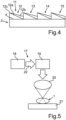
- phase grating 11 For a possible embodiment of the phase grating 11, reference is made to the very simplified and schematic representation in Fig.4 There you can see a section of the optical
- Part 2 is shown and a very simplified sectional view through the optical part 2 is shown, with the main optical axis A lying in this sectional plane.
- the phase grating 11 is shown here as a blaze grating.
- the optical side 4 and the optical side 5 are each uneven, in particular curved, whereby a spherical or aspherical curvature can be formed here.
- the optical side 4 is not curved, but is shown in a simplified flat state.
- phase grating 11 is formed on the optical side 4.
- This phase grating 11 is also formed as a laser structure and produced with the laser device explained below.
- the phase grating 11 has several grating regions 12, 13, 14 and 15.
- the number and individual shape of the grating regions 12 to 15 are to be understood as examples and schematic and not exhaustive.
- the grating regions 12 to 15 are formed as stepped zones relative to one another. It is preferably provided that the phase grating 11 is achromatized for at least two wavelengths.
- the grating region 12 has a first sub-region 12a and a second sub-region 12b.
- the two sub-regions 12a and 12b have different refractive indices. This is produced by the action of a laser beam on the material of the optical part 2.
- the phase grating 11 is advantageously made of the same material as the optical part 2.
- the sub-region 12b located further out is influenced in particular in such a way that the refractive index changes, whereby a change in the material configuration is produced by this laser beam and the change in the refractive index results from this.
- the sub-region 12a has in particular the unchanged refractive index corresponding to the material of the optical part 2.
- the outer partial region 12b whose refractive index is changed by the action of the laser beam, is triangular in shape in this cross-sectional view. It widens from a zone tip 12c towards the adjacent second grating region 13 and it has its greatest widening in particular at the preferably formed mouth on the adjacent grating region 13.
- a corresponding design is also provided in at least one further grating region 13 to 15, as is also shown in Fig.4 is indicated.
- Fig.3 a simplified representation of the optical part 2 of a further embodiment of the artificial eye lens 1 is shown.
- the design of the amplitude grating 6, which is additional to the birefringent structure 2a is not formed with circumferential rings as grating regions 8, 9, 10, but that it is produced by several individual local regions which are spaced apart in the direction of rotation around the main optical axis A and are preferably formed equidistant from one another.
- the individual local regions are each formed by several perforation zones which can also be filled at least in regions, in particular, with one or more dyes.
- the grating region 8 has several local regions which, in an individual design, are designed differently from local regions of the grating region 10, which is located further inside, for example.
- a grating region here the grating region 9 corresponds to the design in Fig.2
- the grid area 8 is correspondingly Fig. 2 and only the grid area 10 as shown in Fig.3
- the grid area 10 is designed in accordance with the design in Fig. 2 is realized and only the grid area 8 according to the design in Fig.3
- the grid area 9 is designed to be interrupted in individual local areas, as is the case with the designs in Fig.3 intended for grid areas 8 and 10.
- a further optically effective grating structure 16 ( Fig. 2 and Fig. 3 ) on or in the optical part 2.
- This further separate optical grating structure 16 has at least one holographic grating.
- This further optical grating structure 16 is preferably designed as a laser structure and in particular with the laser device as described below. Fig.5 is explained.
- this optical structure 16 has two separate holographic gratings, a first holographic grating and a second holographic grating.
- a distance measured in the direction of the main optical axis A between the two holographic gratings is smaller than the distance measured in the direction of the main optical axis A between the first optical side 4 and the second optical side 5.
- the at least two holographic gratings are superimposed and in particular superimposed in such a way that a moiré structure is formed.
- this optical structure 16 is designed as a central circular zone around the main optical axis A of the optical part 2.
- a schematic representation of a laser device 17 is shown, which is designed to produce a multifocal, artificial eye lens 1.
- this laser device 17 enables the generation of the amplitude grating 6 and/or the phase grating 11 and/or the at least one further optical grating structure 16.
- the laser device 17 has at least one laser 18, which is an ultrashort pulse laser.
- This laser device 17 has a scanner 19, which can be adjusted in particular three dimensions, by means of which a pulsed laser beam of the laser 18 can be adjusted.
- the laser device 17 also has a focusing optics 20, which is arranged downstream of the scanner 19 in the beam path.
- the laser device 17 also has a holder 21 on which the artificial eye lens 1 is applied in order to then be able to apply the desired structuring with the laser beam 22 focused by the focusing optics 20.
- the pulsed laser beam 22 with its laser pulses is generated in particular with a pulse length between 100 fs and 20 ps, in particular a wavelength between 200 nm and 1,100 nm, in particular a pulse repetition rate between 1 kHz and 10 MHz, in particular a focus diameter of less than 5 ⁇ m and in particular a power density of greater than 10 8 W/cm 2 .
- the focusing optics 20 can have a numerical aperture of greater than 0.1, preferably greater than 0.3 and in particular greater than 0.5.
- the laser device 17 also makes it possible to generate focus diameters of less than 5 ⁇ m, in particular less than 2 ⁇ m.
- a power density of the focused laser beam of more than 10 10 W/cm 2 is useful in order to achieve an optical breakthrough (photodisruption) of the polymer material of the artificial eye lens, for example if there is no linear absorption of the Polymer material supports this effect.
- a power density of less than 10 10 W/cm 2 is also provided, which does not lead to photodisruption, but can change optical and/or mechanical or associated hygroscopic material properties.
- a repetition rate of the ultrashort laser pulses of the laser beam 22 in the range of 1 kHz to 10 MHz is advantageous. Pulse energies in the sub- ⁇ J range are used. In particular with a repetition rate of greater than 1 MHz, a pulse energy of less than 1 ⁇ J is also provided due to cumulative interaction effects.
Landscapes
- Health & Medical Sciences (AREA)
- Ophthalmology & Optometry (AREA)
- Engineering & Computer Science (AREA)
- Biomedical Technology (AREA)
- Vascular Medicine (AREA)
- Cardiology (AREA)
- Oral & Maxillofacial Surgery (AREA)
- Transplantation (AREA)
- Manufacturing & Machinery (AREA)
- Heart & Thoracic Surgery (AREA)
- Mechanical Engineering (AREA)
- Life Sciences & Earth Sciences (AREA)
- Animal Behavior & Ethology (AREA)
- General Health & Medical Sciences (AREA)
- Public Health (AREA)
- Veterinary Medicine (AREA)
- Prostheses (AREA)
Description
- Die Erfindung betrifft eine künstliche Augenlinse mit einem optischen Teil, der eine in Richtung einer optischen Hauptachse der künstlichen Augenlinse betrachtet erste optische Seite und eine gegenüberliegende zweite optische Seite aufweist, wobei der optische Teil eine diffraktive Gitterstruktur aufweist, die zur optischen Abbildungseigenschaft des optischen Teils beiträgt. Des Weiteren betrifft die Erfindung auch ein Verfahren zum Herstellen einer derartigen künstlichen Augenlinse mittels eines Lasers.
- Multifokale, künstliche Augenlinsen sind aus dem Stand der Technik vielfältigst bekannt. Insbesondere sind dazu Intraokularlinsen bekannt, die die natürliche Linse im Auge ersetzen und diesbezüglich implantiert sind.
- Aus der
US 2015/073549 A1 ist eine Augenlinse bekannt. Diese weist im optischen Teil eine Lochblende auf. - Aus der
US 2010/0082017 A1 ist eine Intraokularlinse bekannt, bei welcher in einem haptischen Teil als auch in einem optischen Teil Schlitze ausgebildet sind, um die mechanische Charakteristik und auch die Strukturcharakteristik der Linse zu modifizieren. Diese länglichen Schlitze sind im Inneren der Intraokularlinse ausgebildet, insbesondere mit einem Laser. - Darüber hinaus ist aus der
US 2004/0032566 A1 ein Verfahren zur Markierung einer Intraokularlinse mittels Laser bekannt. Mit dem Laser wird eine Mikroperforierung des optischen Teils der Linse durchgeführt. - Darüber hinaus ist aus der
US 2014/0135920 A1 ein Herstellungsverfahren für eine Intraokularlinse bekannt, bei welchem mit einem Laserstrahl eines Ultrakurzpulslasers das hydrophile Verhalten des Polymerwerkstoffes, aus dem die künstliche Augenlinse bereits hergestellt ist, verändert wird. Durch diese Veränderung des hydrophilen Verhaltens des Polymerwerkstoffes wird eine Reduktion des optischen Brechungsindexes dieses Polymerwerkstoffes erzeugt. - Als weitere bekannte Herstellungsmöglichkeit ist beispielsweise eine Ultrapräzisionsbearbeitung genannt. Dort wird mit einem monokristallinen Diamantwerkzeug gearbeitet, indem dieses Werkzeug mechanisch auch direkt auf den Kunststoff, aus welchem die Augenlinse erzeugt werden soll, einwirkt. Diese Technologie arbeitet mit geometrisch bestimmtem, monokristallinem Diamantwerkzeug entsprechend den klassischen spanenden Verfahren, wie Drehen oder Fräsen. Für diese Herstellungsverfahren sind jedoch sehr stabile Maschinen und gleichbleibende Umgebungsbedingungen erforderlich. Typischerweise ist hier die Fertigungsumgebung klimatisiert und schwingungsgedämpft. Daher ist die Herstellung sehr aufwendig.
- Mithilfe der Ultrapräzisionsbearbeitung können neben der oben genannten direkten Bearbeitung der Kunststoffoptiken auch Abformwerkzeuge bereitgestellt werden, mit denen dann in einem Gieß-Prozess die Augenlinse abgeformt werden kann, was auch kostengünstiger ist.
- Die Herstellung von sehr komplexen Profilen an der Oberfläche eines optischen Teils ist dabei jedoch eingeschränkt und das Herstellen von optisch wirksamen Strukturen im Inneren des optischen Teils nicht möglich. Mit einem Laser erzeugte Strukturen haben demgegenüber Vorteile.
- Bei bekannten künstlichen Augenlinsen, insbesondere bei Intraokularlinsen, treten unerwünschte Beugungsordnungen auf, die deren optische Funktionalität einschränken. Diese unerwünschten Beugungsordnungen treten auch unabhängig von den bekannten Herstellungsverfahren mehr oder minder stark auf. Gerade Halos und Glares sind hier als störende Beeinträchtigungen zu nennen. Als Halos werden Lichteffekte bezeichnet, die durch Brechung und Reflexion von Licht beispielsweise Lichthöfe um Lampen, Scheinwerfer und andere Lichtquellen erzeugen. Sie treten auch als Lichtringe auf. Gerade bei Dämmerung oder in der Nacht sind dies besonders unerwünschte Effekte, die auch zur Fehlwahrnehmung führen können. Gerade bei Dämmerung und in der Nacht treten Halos bei relativ scharfen Hell-Dunkel-Übergängen auf, wodurch neben einem Blenden eines Auges allgemein auch das Sehen für einen Augenlinsenträger relativ anstrengend ist. Als Glares werden Blendeffekte bezeichnet. Sie treten insbesondere bei direkter Einstrahlung von hellem Licht auf, beispielweise in der Dämmerung oder in Dunkelheit, wenn eine helle Lichtquelle in Richtung des Beobachters strahlt. Auch direkt eingestrahltes oder reflektiertes Sonnenlicht erzeugt derartige Blendeffekte.
- Es ist Aufgabe der Erfindung, eine künstliche Augenlinse und ein Verfahren zum Herstellen einer künstlichen Augenlinse zu schaffen, bei welcher bzw. mit welchem das Auftreten von störenden Lichteffekten wie Halos und Glares zumindest reduziert ist.
- Ein Aspekt der Erfindung betrifft eine künstliche Augenlinse, die einen optischen Teil aufweist, mittels welchem die optische Abbildungseigenschaft der Augenlinse charakterisiert ist. Dieser optische Teil weist eine erste optische Seite und eine in Richtung der optischen Hauptachse dieser Augenlinse betrachtet gegenüberliegende zweite optische Seite auf. Die künstliche Augenlinse weist des Weiteren eine Haptik auf. Mit der Haptik ist die künstliche Augenlinse positionell in einem Auge gehalten. Die künstliche Augenlinse weist zusätzlich oder anstatt der Haptik eine den optischen Teil zumindest bereichsweise umgebende und zur Haptik unterschiedliche Einfassung auf. Diese Einfassung ist dann weder Bestandteil des optischen Teils noch ist sie Bestandteil insbesondere von Bügeln einer Haptik, wenn eine derartige Haptik vorhanden ist.
- Die künstliche Augenlinse weist eine diffraktive Gitterstruktur auf, die zur optischen Abbildungseigenschaft des optischen Teils beiträgt. Die diffraktive Gitterstruktur ist im optischen Teil der künstlichen Augenlinse ausgebildet. Diese diffraktive Gitterstruktur ist ein Amplitudengitter, welches darüber hinaus in dem insbesondere einstückig ausgebildeten optischen Teil der künstlichen Augenlinse als Laserstruktur ausgebildet ist. Ein Amplitudengitter ist ein absorbierendes Gitter. Ein Amplitudengitter ist derart ausgebildet, dass es die Amplitude der einfallenden Lichtwelle moduliert. Ein Amplitudengitter ist ein optisches Gitter, welches einfallendes Licht teilweise absorbiert.
- Ein Amplitudengitter kann als Transmissionsgitter oder als Reflexionsgitter ausgebildet sein. Durch die Ausgestaltung eines derartig spezifischen optischen Gitters als Laserstruktur ist es einerseits äußerst präzise herstellbar, andererseits kann es lokal sehr definiert an unterschiedlichen Stellen des optischen Teils erzeugt werden. Durch die spezifische Ausgestaltung eines derartigen Amplitudengitters können unerwünschte Beugungsordnungen der künstlichen Augenlinse unterdrückt werden. Damit wird insbesondere auch die Kontrastverbesserung des optischen Systems ermöglicht. Insbesondere ist es durch eine derartige Ausgestaltung einer diffraktiven Gitterstruktur als Amplitudengitter, welches als Laserstruktur ausgebildet ist, auch möglich, Halos und Glares in besonders vorteilhafter Weise zumindest deutlich zu reduzieren. Unerwünschte Blendungen und Reflexionseffekte, wie sie durch diese spezifischen, optisch störenden Effekte auftreten, können dadurch deutlich reduziert werden.
- In einer vorteilhaften Ausführung ist das Amplitudengitter als Mikroperforation in dem optischen Teil ausgebildet. Dies ist eine besonders vorteilhafte Ausführung, wenn ein derartig spezifisches optisches Gitter als Laserstruktur erzeugt ist. Wird durch eine Mikroperforation ein Amplitudengitter gestaltet, ermöglicht dies eine höchst präzise Ausgestaltung der einzelnen Strukturbereiche dieses Amplitudengitters. Dadurch wird die optische Wirkung des Amplitudengitters in besonders vorteilhafter Weise erreicht. Andererseits wird durch eine derartige Ausgestaltung eine sehr konturenscharfe Ausgestaltung der Konturbereiche des Amplitudengitters erreicht, sodass gerade auch an Randbereichen des Amplitudengitters nicht mehr zum Amplitudengitter zugehörige Bereiche des optischen Teils nicht unerwünscht beeinträchtigt werden und deren optische Abbildungseigenschaft daher nicht unerwünscht verfälscht wird. Gerade durch die Ausgestaltung als Mikroperforation lassen sich auch sehr feindosierte Unterschiede in den Strukturbereichen des Amplitudengitters herstellen, sodass auch hier sehr individuelle optische Abbildungseigenschaften des Amplitudengitters in sich selbst geschaffen werden können.
- Durch eine Ausgestaltung des Amplitudengitters als Mikroperforation kann auch in besonders vorteilhafter Weise die im optischen Teil innenliegende Ausgestaltung des Amplitudengitters geschaffen werden. Das Amplitudengitter liegt bei einer diesbezüglich vorteilhaften Ausführung somit vollständig im Inneren des optischen Teils und tritt daher nicht als Oberflächenstruktur auf. Durch diese Ausgestaltung ist das Amplitudengitter auch für sich betrachtet vollständig von dem Werkstoff des optischen Teils umgeben und durch Perforation des Werkstoffs des optischen Teils durch Einwirken der Laserstrahlung erst gebildet. Diese innenliegende und somit eingebettete Ausgestaltung des Amplitudengitters ermöglicht die oben genannten Vorteile im besonderen Maße und schafft darüber hinaus auch noch die Situation, dass das Amplitudengitter vor unerwünschten mechanischen Einwirkungen geschützt ist. Gerade beim Herstellen der künstlichen Augenlinse und bei dann erfolgter weiterer Lagerung vor dem Implantieren der künstlichen Augenlinse können daher keine direkten mechanischen Einwirkungen auf dieses Amplitudengitter erfolgen und somit auch keine Beschädigungen dieses Amplitudengitters hervorgerufen werden.
- In einer weiteren vorteilhaften Ausführung weist das Amplitudengitter einen ersten Gitterbereich auf, der mit einer ersten Perforationsdichte von Perforationszonen der Mikroperforation und/oder mit einer ersten Dimensionierung von Perforationszonen der Mikroperforation ausgebildet ist. Das Amplitudengitter weist insbesondere einen zweiten Gitterbereich auf, der mit einer zur ersten Perforationsdichte von Perforationszonen unterschiedlichen zweiten Perforationsdichte von Perforationszonen der Mikroperforation und/oder mit einer zur ersten Dimensionierung von Perforationszonen der Mikroperforation unterschiedlichen zweiten Dimensionierung von Perforationszonen der Mikroperforation ausgebildet ist. Damit lassen sich hochpräzise und somit optisch hochfunktionelle Amplitudengitterbereiche schaffen, die auch relativ klein und/oder formspezifisch individuell ausgebildet werden können. Damit kann das Amplitudengitter auch mit unterschiedlichen Abschwächungsgraden beziehungsweise Grauwerten und somit mit ganz individuellen Absorptionswerten für das einfallende Licht ausgebildet werden. Die oben genannten unerwünschten optischen Beugungs- und Reflexionseffekte können dadurch weiter reduziert werden.
- Insbesondere ist es auch möglich, eine Lage und/oder eine Anzahl von lichtundurchlässigen Gitterbereichen des Amplitudengitters abhängig von diesen Parametern, nämlich der Perforationsdichte der Perforationszone der Mikroperforation und/oder der Dimensionierung von Perforationszonen der Mikroperforation auszubilden. Die Dimensionierung einer Perforationszone kann ein Innenmaß und/oder eine Tiefe sein. Je nach Formgebung einer derartigen Perforationszone können somit individuelle Ausgestaltungen des Amplitudengitters realisiert sein.
- In einer vorteilhaften Ausführung kann vorgesehen sein, dass zumindest eine Perforationszone der Mikroperforation zumindest bereichsweise mit einem Farbstoff gefüllt ist. Durch eine derartige zusätzliche Werkstoffzugabe kann das Amplitudengitter nochmals verbessert und mit unterschiedlichen und feiner abgestuften Abschwächungsgraden beziehungsweise Grauwerten realisiert werden. Die Variabilität und Flexibilität der Gitterstruktur ist darüber hinaus erhöht. Nicht zuletzt ist auch eine besonders hohe Präzision der Gitterstrukturen im Mikrometerbereich einschreibbar. Durch spezifische absorbierende Farbstoffe kann hier die optische Funktionalität des Amplitudengitters ganz individuell beeinflusst werden. Es können somit einzelne Perforationszonen mit diesem Farbstoff und/oder unterschiedlichen Farbstoffen, die unterschiedlich absorbieren, zumindest bereichsweise gefüllt sein. Die primäre Funktionalität eines Amplitudengitters, nämlich individuelles Absorptionsverhalten in unterschiedlichen Bereichen, lässt sich hier in hochvariabler und äußerst flexibler Weise individuell gestalten. Dies ist insbesondere auch durch die Gestaltung des Amplitudengitters als Laserstruktur ermöglicht, da hier auch unterschiedliche Perforationszonendichten und unterschiedliche Größen der Perforationszonen sehr genau und somit lagepräzise und formpräzise gestaltet werden können. Die dann gegebenenfalls individuelle Befüllung mit einem oder mehreren Farbstoffen, die individuelles Absorptionsverhalten aufweisen, ermöglicht auch, dass besonders unterschiedliche und fein dosierte Absorptionsverhalten eines Amplitudengitters ausgebildet werden können.
- In einer vorteilhaften Ausführung ist der Farbstoff in zumindest einer Perforationszone polymerisiert. Dadurch wird die Langzeitstabilität des Farbstoffs verbessert. Eine Polymerisation kann beispielsweise durch UV (Ultraviolett)-Licht oder durch eine Multiphotonenpolymerisation mit Laserlicht erfolgen.
- Insbesondere ist eine Lage und/oder eine Anzahl von lichtundurchlässigen Gitterbereichen des Amplitudengitters abhängig von der Art des Farbstoffs und/oder abhängig von der Menge des Farbstoffs und/oder abhängig von der Anzahl der mit Farbstoff zumindest bereichsweise gefüllten Perforationszonen und/oder abhängig von der Lage der mit Farbstoff zumindest bereichsweise gefüllten Perforationszonen ausgebildet. Die bereits oben dargelegte hohe Variabilität und der Individualisierungsgrad eines erzeugbaren Amplitudengitters sind dadurch wesentlich erhöht. Dies ist insbesondere durch die Ausgestaltung des Amplitudengitters als Laserstruktur ermöglicht, da mit einem Laser die bereits oben umfänglich dargelegten Vorteile bezüglich der grundsätzlichen Erzeugung eines derartigen Amplitudengitters als auch bezüglich deren Lagegenauigkeit und hoher optischer Funktionalität erst erreicht ist.
- In einer vorteilhaften Ausführung weist das Amplitudengitter um eine optische Hauptachse des optischen Teils zumindest bereichsweise umlaufende Gitterringe als Gitterbereiche auf. Durch eine derartige Strukturierung des Amplitudengitters können spezifisch absorbierend wirkende Ringzonen geschaffen werden, die dann auch eine vorzugsweise geometrisch betrachtet symmetrische Ausgestaltung um die optische Hauptachse aufweisen und in dieser azimutalen Richtung eine einheitliche Wirkung bezüglich der optischen Eigenschaft aufweisen.
- Insbesondere ist das Amplitudengitter vollständig innenliegend in dem optischen Teil ausgebildet. Dies bedeutet, dass es vollständig von dem Werkstoff des optischen Teils umgeben ist und somit an den optischen Seiten des optischen Teils nicht außenliegend und somit freiliegend ausgebildet ist. Die dadurch erreichbaren Vorteile sind bereits oben erwähnt.
- Mit den oben genannten Ausführungen lässt sich eine individuelle Aperturblende ausbilden, mit welcher die Schärfentiefe des Auges vergrößert wird.
- In einer vorteilhaften Ausführung ist auf zumindest einer Seite des optischen Teils eine zum Amplitudengitter separate optische Gitterstruktur ausgebildet. Durch zwei separate optische Gitterstrukturen können die optischen Abbildungseigenschaften verbessert werden und insbesondere störende optische Effekte nochmals besser unterdrückt werden. Insbesondere können hier auch dann unterschiedliche optische Störeffekte besser unterdrückt werden.
- Insbesondere ist die weitere separate optische Gitterstruktur ein Phasengitter. Phasengitter sind optische Beugungsgitter, welche die Phase der einlaufenden Lichtwelle beeinflussen. Im Unterschied zu einem Amplitudengitter, welches ein absorbierendes optisches Gitter ist, ist ein Phasengitter ein Wellenumformgitter, welches die Wellenfront der eintreffenden Lichtquelle umformt. Ein Phasengitter kann auch als Transmissionsgitter oder als Reflexionsgitter ausgebildet sein. Gerade in Kombination mit einem Amplitudengitter können die optischen Abbildungseigenschaften verbessert werden und die eingangs genannten störenden Beugungs- oder Reflexionseffekte verbessert reduziert werden, insbesondere auch zu den genannten Halos und Glares, die im Wesentlichen durch das Amplitudengitter zumindest deutlich reduziert werden können, unterschiedliche störende Beugungseffekte und Reflexionseffekte reduziert werden.
- In einer weiteren sehr vorteilhaften Ausführung ist vorgesehen, dass dieses Phasengitter für zumindest zwei Wellenlängen achromatisiert ist. Dadurch ist die Beugungseffizienz für bestimmte Beugungsordnungen maximiert. Dazu wird möglichst viel Intensität in spezifische gewünschte Beugungsordnungen konzentriert, in den übrigen Beugungsordnungen, beispielsweise auch in der nullten Beugungsordnung, hingegen minimiert. Durch vorteilhafte Ausführung ist nun erreicht, dass in spezifischen Gitterbereichen dieses Phasengitters eine spezifische Brechzahlmodifikation ausgebildet ist, um diese Achromatisierung für zumindest zwei Wellenlängen auszubilden. Diese Brechzahlmodifikation ist mit einem Laser, insbesondere einem Ultrakurzpulslaser, erzeugt. Durch eine Achromatisierung wird die Phasendifferenz der interferierenden Wellen von der Wellenlänge unabhängig gemacht. Dies erfolgt bei der genannten vorteilhaften Ausführung für zumindest zwei unterschiedliche Wellenlängen.
- Das oben genannte Phasengitter kann beispielsweise ein Blazegitter sein.
- Es kann vorgesehen sein, dass zumindest eine optische Seite des optischen Teils, wie sie oben genannt wurden, sphärisch oder asphärisch ausgebildet ist. Es kann eine torische Ausgestaltung und somit ein torisches Oberflächenprofil zumindest auf einer dieser optischen Seite ausgebildet sein. Auch anderweitige optische Oberflächenprofile können auf einer derartigen optischen Seite des optischen Teils ausgebildet sein. Beispielsweise können hier ringförmige Zonen ausgebildet sein, die Bestandteil eines weiteren diffraktiven Elements sein können. Diese ringförmigen Zonen sind dann jedoch auf dieser optischen Seite ausgebildet und somit außenliegende und somit freiliegende optische Strukturelemente.
- Insbesondere mit einem Ultrakurzpulslaser einer Laser-Vorrichtung wird der optische Teil der künstlichen Augenlinse derart bearbeitet, dass das Amplitudengitter und gegebenenfalls zumindest ein weiteres optisches Gitter erzeugt werden. Insbesondere werden die Parameter der Laser-Vorrichtung so eingestellt, dass im Fokuspunkt des Laserstrahls eine Laserdisruption im transparenten Kunststoff des optischen Teils der künstlichen Augenlinse kurz über dem Schwellwert auftritt. Wird eine Steigerung der Intensität des Laserstrahls eingestellt, werden größere Schädigungsvolumina in diesem Kunststoff erzeugt. Die meist als Blasenbildung in dem Kunststoff auftretenden Laserdisruptionen können bei ausreichender Energie, beispielsweise im Mikrojoule-Bereich, im Einzelschuss erfolgen oder mit niedriger Energiedichte im Nanojoule-Bereich durch eine hohe Repetitionsrate im Kilohertz- bis Megahertz-Bereich erzeugt werden.
- In einer vorteilhaften Ausführung kann auch vorgesehen sein, dass die künstliche Augenlinse eine weitere optische Gitterstruktur aufweist, welche als holographisches Gitter ausgebildet ist. Es kann vorgesehen sein, dass bei einer vorteilhaften Ausführung diese Gitterstruktur ein erstes holographisches Gitter und ein zweites holographisches Gitter aufweist. Insbesondere kann durch diese zwei holographischen Gitter eine Moiré-Struktur erzeugt werden. Vorzugsweise ist ein in Richtung der optischen Hauptachse bemessener Abstand zwischen den beiden holographischen Gittern kleiner dem in Richtung der optischen Hauptachse bemessenen Abstand zwischen der ersten optischen Seite und der zweiten optischen Seite ausgebildet. Insbesondere ist zumindest ein holographisches Gitter im optischen Teil der künstlichen Augenlinse völlig innenliegend zwischen den optischen Seiten des optischen Teils ausgebildet.
- Es kann vorgesehen sein, dass auf die erste optische Seite oder auf die zweite optische Seite des optischen Teils zumindest eine Beschichtung aufgebracht ist und zumindest ein holographisches Gitter in dieser Beschichtung ausgebildet ist. Der optische Teil kann zumindest einen laminierten Bereich aufweisen und zumindest ein holographisches Gitter ist in diesem laminierten Bereich ausgebildet.
- Insbesondere ist auch dieses holographische Gitter als Laserstruktur in dem optischen Teil ausgebildet.
- Durch eine derartige spezifische Ausgestaltung einer Gitterstruktur, insbesondere mit zumindest zwei unterschiedlichen separaten holographischen Gittern, die insbesondere spezifisch überlagert sind, kann eine individuelle Brechkraft der Augenlinse erzeugt werden. Um diese optisch aktive Gitterstruktur, vorzugsweise Moiré-Struktur, innerhalb der Kohärenzlänge des Lichts erzeugen zu können, werden zumindest zwei derartige beugende Strukturen in Form der holographischen Gitter mittels eines Lasers als Laserstruktur erzeugt, insbesondere innerhalb entsprechend benachbarter Schichten eines optischen Teils der Augenlinse. Es kann dabei eine positive als auch eine negative Änderung des Brechungsindex in dem Kunststoff erzeugt werden.
- Die künstliche Augenlinse ist insbesondere eine multifokale, insbesondere zumindest trifokale, künstliche Augenlinse. Die künstliche Augenlinse ist insbesondere eine Intraokularlinse. Insbesondere ist der optische Teil der künstlichen Augenlinse einstückig ausgebildet. Der optische Teil weist bevorzugt einen Durchmesser von größer als 2 mm, insbesondere größer oder gleich 3 mm auf. Das Amplitudengitter in dem optischen Teil ist in einem radialen Abstand von größer oder gleich 1 mm zur optischen Hauptachse ausgebildet.
- Des Weiteren betrifft die Erfindung auch ein Verfahren zum Herstellen einer multifokalen, künstlichen Augenlinse gemäß der oben genannten Aspekte, bei welchem eine optisch wirksame Struktur mit einer Laser-Vorrichtung erzeugt wird und ein gepulster Laserstrahl mit einer Pulslänge zwischen 100 fs und 20 ps, einer Wellenlänge zwischen 320 nm und 1.100 nm, einer Pulswiederholrate zwischen 1 kHz und 10 MHz, einem Fokusdurchmesser von kleiner als 5 µm, insbesondere von kleiner als 2 µm, und einer Leistungsdichte von größer als 106 W/cm2, erzeugt wird und auf den Werkstoff der künstlichen Augenlinse einwirkt. Vorzugsweise beträgt die Pulslänge 300 fs und die Wellenlänge vorzugsweise 1.060 nm oder 532 nm oder 355 nm. Durch eine disruptive Bearbeitung kann vorzugsweise eine Wellenlänge von 256 nm und bevorzugt von 213 nm für insbesondere ablative Bearbeitung vorgesehen sein.
- Weitere Merkmale der Erfindung ergeben sich aus den Ansprüchen, den Figuren und der Figurenbeschreibung. Die vorstehend in der Beschreibung genannten Merkmale und Merkmalskombinationen, sowie die nachfolgend in der Figurenbeschreibung genannten und/oder in den Figuren alleine gezeigten Merkmale und Merkmalskombinationen sind nicht nur in der jeweils angegebenen Kombination, sondern auch in anderen Kombinationen verwendbar, ohne den Rahmen der Erfindung zu verlassen. Es sind somit auch Ausführungen von der Erfindung als umfasst und offenbart anzusehen, die in den Figuren nicht explizit gezeigt und erläutert sind, jedoch durch separierte Merkmalskombinationen aus den erläuterten Ausführungen hervorgehen und erzeugbar sind. Es sind auch Ausführungen und Merkmalskombinationen als offenbart anzusehen, die somit nicht alle Merkmale eines ursprünglich formulierten unabhängigen Anspruchs aufweisen. Es sind darüber hinaus Ausführungen und Merkmalskombinationen, insbesondere durch die oben dargelegten Ausführungen, als offenbart anzusehen, die über die in den Rückbezügen der Ansprüche dargelegten Merkmalskombinationen hinausgehen oder abweichen.
- Die in den Unterlagen angegebenen konkreten Werte von Parametern und Angaben zu Verhältnissen von Parametern bzw. Parameterwerten zur Definition von Ausführungsbeispielen der Augenlinse sind auch im Rahmen von Abweichungen, beispielsweise aufgrund von Messfehlern, Systemfehlern, DIN-Toleranzen etc. als vom Rahmen der Erfindung mit umfasst anzusehen, wodurch auch Erläuterungen, die sich auf im Wesentlichen entsprechende Werte und Angaben beziehen darunter zu verstehen sind.
- Ausführungsbeispiele der Erfindung werden nachfolgend anhand schematischer Zeichnungen näher erläutert. Es zeigen:
- Fig. 1a
- eine perspektivische schematische und vereinfachte Darstellung eines ersten Ausführungsbeispiels einer erfindungsgemäßen künstlichen Augenlinse;
- Fig. 1b
- eine perspektivische schematische und vereinfachte Darstellung eines weiteren Ausführungsbeispiels einer erfindungsgemäßen künstlichen Augenlinse;
- Fig. 2
- eine Draufsicht auf ein Ausführungsbeispiel eines optischen Teils einer künstlichen Augenlinse mit einem spezifischen ersten Amplitudengitter;
- Fig. 3
- eine Draufsicht auf ein Ausführungsbeispiel eines optischen Teils einer künstlichen Augenlinse mit einem spezifischen zweiten Amplitudengitter;
- Fig. 4
- eine schematische Schnittdarstellung eines Ausführungsbeispiels einer künstlichen Augenlinse mit einem Phasengitter im optischen Teil; und
- Fig. 5
- eine vereinfachte Darstellung einer Laser-Vorrichtung zum Herstellen einer künstlichen Augenlinse.
- Bevorzugte Ausführungen der Erfindung
- In den Figuren werden gleiche oder funktionsgleiche Elemente mit den gleichen Bezugszeichen versehen.
- In
Fig. 1a ist in einer perspektivischen Darstellung ein erstes Ausführungsbeispiel einer künstlichen Augenlinse 1 gezeigt, die hier eine Intraokularlinse ist. Die nachfolgend als Augenlinse 1 bezeichnete künstliche Augenlinse 1 weist einen optischen Teil 2 und daran anschließend eine Haptik 3 auf. Die Augenlinse 1 ist multifokal, insbesondere trifokal. Die Augenlinse 1 ist faltbar und über einen Kleinschnitt in ein Auge einführbar. Der optische Teil 2, der wesentlich für die optische Abbildungseigenschaft der Augenlinse 1 ist, umfasst eine optische Hauptachse A. Der optische Teil 2 weist darüber hinaus in Richtung dieser optischen Hauptachse A betrachtet eine erste optische Fläche bzw. optische Seite 4 auf, die eine Vorderseite sein kann, und weist gegenüberliegend eine zweite optische Fläche bzw. optische Seite 5 auf, die eine Rückseite sein kann. Die Vorderseite ist im implantierten Zustand der Augenlinse 1 im Auge der Hornhaut zugewandt, wohingegen die Rückseite dieser Hornhaut abgewandt ist. - In
Fig. 1b ist in einer perspektivischen Darstellung ein weiteres Ausführungsbeispiel einer als Intraokularlinse ausgebildeten künstlichen Augenlinse 1 gezeigt. Sie unterscheidet sich von der Ausführung inFig. 1a durch die unterschiedliche Haptik 3. Mittels der Haptik 3 ist die Augenlinse 1 im Auge gehalten. - Die optischen Seiten 4 und 5 sind in den Ausführungen uneben, insbesondere konvex, gekrümmt. Auf zumindest einer optischen Seite 4, 5 ist auf dieser konvexen Grundform ein diffraktives Profil ausgebildet.
- Grundsätzlich können auch anderweitig geformte und ausgestaltete Haptiken 3 vorgesehen sein.
- In
Fig. 2 ist in einer vereinfachten Darstellung der optische Teil 2 mit Blick auf die optische Seite 4 gezeigt. Die Augenlinse 1 könnte zusätzlich oder anstatt dazu auch mit Blick auf die optische Seite 5 entsprechend ausgebildet sein. Im Ausführungsbeispiel ist vorzugsweise im Inneren des optischen Teils 2, der vorzugsweise diskusförmig ausgebildet ist, ein diffraktives Gitter beziehungsweise eine diffraktive Gitterstruktur ausgebildet, die ein Amplitudengitter 6 ist. Das Amplitudengitter 6 ist als Laserstruktur ausgebildet. Das Amplitudengitter 6 ist insbesondere vollständig innerhalb des optischen Teils 2 angeordnet und durch einen Laser erzeugt. Das Amplitudengitter 6 ist daher vollständig von dem restlichen Werkstoff des optischen Teils 2 umgeben und somit vollständig von diesem Werkstoff umschlossen. - Der optische Teil 2 ist einstückig und somit aus einem einzigen Teil ausgebildet.
- Insbesondere kann das Amplitudengitter 6 auch als Mikroperforation 7 in dem optischen Teil 2 ausgebildet sein.
- Das Amplitudengitter 6 weist einen ersten Gitterbereich 8 auf, der mit einer ersten Perforationsdichte von Perforationszonen der Mikroperforation 7 und/oder mit einer ersten Dimensionierung von Perforationszonen dieser Mikroperforation 7 ausgebildet ist. Das Amplitudengitter 6 weist vorzugsweise einen dazu separaten zweiten Gitterbereich 9 auf, der mit einer zur ersten Perforationsdichte von Perforationszonen der Mikroperforation 7 unterschiedlichen, zweiten Perforationsdichte von Perforationszonen der Mikroperforation 7 und/oder mit einer zur ersten Dimensionierung von Perforationszonen der Mikroperforation 7 unterschiedlichen zweiten Dimensionierung von Perforationszonen der Mikroperforation 7 ausgebildet ist. Insbesondere ist vorgesehen, dass das Amplitudengitter 6 auch noch zumindest einen dritten Gitterbereich 10 aufweisen kann, der mit einer zur ersten und zweiten Perforationsdichte von Perforationszonen der Mikroperforation 7 und/oder mit einer zur ersten und zweiten Dimensionierung von Perforationszonen der Mikroperforation 7 unterschiedlichen dritten Perforationsdichte von Perforationszonen und/oder Dimensionierung von Perforationszonen der Mikroperforation 7 ausgebildet ist.
- Es kann vorgesehen sein, dass sich zumindest ein Gitterbereich 8, 9, 10 in radialer Richtung zur optischen Hauptachse A, die senkrecht auf der Figurenebene steht, wiederholt. Auch eine alternierende Anordnung in dieser radialen Richtung zur optischen Hauptachse A von zumindest zwei Gitterbereichen 8, 9, 10 kann vorgesehen sein.
- In der gezeigten Ausführung gemäß
Fig. 2 sind die einzelnen Perforationszonen der Mikroperforation 7 als Ringzonen ausgebildet, die insbesondere vollständig umlaufend um die optische Hauptachse A ausgebildet sind. Es kann auch eine Ausgestaltung vorgesehen sein, bei welcher zumindest ein Gitterbereich 8, 9, 10 nur teilweise umlaufend um die optische Hauptachse A ausgebildet ist. - Wie zu erkennen ist, ist auch die radiale Dicke eines Gitterbereichs 8, 9, 10 unterschiedlich ausgebildet.
- Insbesondere ist vorgesehen, dass in zumindest einer Perforationszone, vorzugsweise in mehreren Perforationszonen, zumindest eines Gitterbereichs 8, 9, 10 zumindest ein Farbstoff enthalten ist. Das Absorptionsverhalten des Amplitudengitters 6 kann somit unterschiedlich eingestellt werden.
- Es kann vorgesehen sein, dass der zumindest eine absorbierende Farbstoff in zumindest einer Perforationszone polymerisiert ist.
- In einer vorteilhaften Ausführung ist vorgesehen, dass auf der optischen Seite 4 und/oder auf der optischen Seite 5 und somit außenliegend zusätzlich eine weitere optische Gitterstruktur als zum Amplitudengitter 6 separate Gitterstruktur ausgebildet ist. Diese weitere Gitterstruktur ist als separates optisches Gitter ausgebildet und insbesondere als Phasengitter 11 ausgebildet. Der Übersichtlichkeit dienend ist dieses Phasengitter 11 in
Fig. 2 nicht explizit strukturell gezeigt, sondern lediglich mit einem Bezugszeichen angedeutet. - Für eine mögliche Ausführungsform des Phasengitters 11 wird auf die sehr vereinfachte und schematische Darstellung in
Fig. 4 verwiesen. Dort ist ein Ausschnitt des optischen - Teils 2 gezeigt und es ist eine sehr vereinfachte Schnittdarstellung durch den optischen Teil 2 gezeigt, wobei die optische Hauptachse A in dieser Schnittebene liegt.
- Als Beispiel ist hier das Phasengitter 11 als Blazegitter gezeigt. Insbesondere sind die optische Seite 4 und die optische Seite 5 jeweils uneben ausgebildet, insbesondere gekrümmt ausgebildet, wobei hier eine sphärische oder asphärische Krümmung ausgebildet sein kann. Bei der stark vergrößerten Querschnittsansicht in
Fig. 4 ist die optische Seite 4 nicht gekrümmt, sondern vereinfacht in planem Zustand dargestellt. - In
Fig. 4 ist ein Beispiel gezeigt, in welchem das Phasengitter 11 auf der optischen Seite 4 ausgebildet ist. Auch dieses Phasengitter 11 ist als Laserstruktur ausgebildet und mit der nachfolgend noch erläuterten Laser-Vorrichtung erzeugt. Das Phasengitter 11 weist mehrere Gitterbereiche 12, 13, 14 und 15 auf. Die Gitterbereiche 12 bis 15 sind in Anzahl als auch in ihrer individuellen Formgestaltung lediglich als Beispiel und schematisch und nicht abschließend zu verstehen. Die Gitterbereiche 12 bis 15 sind als gestufte Zonen zueinander ausgebildet. Es ist vorzugsweise vorgesehen, dass das Phasengitter 11 für zumindest zwei Wellenlängen achromatisiert ist. - Insbesondere ist vorgesehen, dass der Gitterbereich 12 einen ersten Teilbereich 12a und einen zweiten Teilbereich 12b aufweist. Die beiden Teilbereiche 12a und 12b weisen unterschiedliche Brechzahlen auf. Dies ist durch Einwirkung mit einem Laserstrahl auf den Werkstoff des optischen Teils 2 erzeugt. Grundsätzlich ist in vorteilhafter Weise das Phasengitter 11 aus dem gleichen Werkstoff wie der optische Teil 2 ausgebildet. Unter Einwirkung mit einem Laserstrahl wird insbesondere der weiter außen liegende Teilbereich 12b derart beeinflusst, dass sich die Brechzahl ändert, wobei hier durch diesen Laserstrahl eine Veränderung der Werkstoffkonfiguration erzeugt wird und sich daraus die Brechzahländerung ergibt. Der Teilbereich 12a hingegen weist insbesondere die unveränderte Brechzahl entsprechend dem Werkstoff des optischen Teils 2 auf. Wie in der ebenfalls nicht einschränkend zu verstehenden Ausführungsform in
Fig. 4 zu erkennen ist, ist der äußere und in seiner Brechzahl durch Einwirkung des Laserstrahls veränderte Teilbereich 12b in dieser Querschnittdarstellung dreieckförmig ausgebildet. Er weitet sich von einer Zonenspitze 12c her betrachtet zu dem benachbarten zweiten Gitterbereich 13 hin auf und er weist insbesondere dann an der vorzugsweise ausgebildeten Anmündung an dem benachbarten Gitterbereich 13 seine größte Aufweitung auf. - Insbesondere ist eine entsprechende Ausgestaltung auch bei zumindest einem weiteren Gitterbereich 13 bis 15 ausgebildet, wie dies ebenfalls in
Fig. 4 angedeutet ist. - In
Fig. 3 ist eine ebenfalls vereinfachte Darstellung des optischen Teils 2 eines weiteren Ausführungsbeispiels der künstlichen Augenlinse 1 gezeigt. Im Unterschied zur Darstellung gemäßFig. 2 ist hier vorgesehen, dass die Ausgestaltung des zur doppelbrechenden Struktur 2a zusätzlichen Amplitudengitters 6 nicht mit umlaufenden Ringen als Gitterbereiche 8, 9, 10 ausgebildet ist, sondern dass diese durch mehrere einzelne Lokalbereiche, die in Umlaufrichtung um die optische Hauptachse A beabstandet und vorzugsweise äquidistant zueinander ausgebildet sind, erzeugt ist. Auch hier sind die einzelnen Lokalbereiche durch jeweils mehrere Perforationszonen, die ebenfalls insbesondere mit einem oder mehreren Farbstoffen zumindest bereichsweise gefüllt sein können, gebildet. Wie hier zu erkennen ist, weist der Gitterbereich 8 mehrere Lokalbereiche auf, die in einer individuellen Ausgestaltung unterschiedlich zu Lokalbereichen des beispielsweise weiter innen liegenden Gitterbereichs 10 gestaltet sind. Insbesondere kann auch vorgesehen sein, dass ein Gitterbereich, hier der Gitterbereich 9, entsprechend der Ausgestaltung inFig. 2 realisiert ist. Ebenso kann eine weitere Alternative dadurch ausgebildet sein, dass beispielsweise der Gitterbereich 8 entsprechend inFig. 2 ausgebildet ist und nur der Gitterbereich 10 gemäß der Darstellung inFig. 3 ausgebildet ist. Ebenso kann es vorgesehen sein, dass der Gitterbereich 10 entsprechend der Ausgestaltung inFig. 2 realisiert ist und nur der Gitterbereich 8 entsprechend der Ausgestaltung inFig. 3 realisiert ist. Ebenso kann es vorgesehen sein, dass der Gitterbereich 9 entsprechend unterbrochen in einzelnen Lokalbereichen gestaltet ist, wie dies bei den Ausführungen inFig. 3 für die Gitterbereiche 8 und 10 vorgesehen ist. - Zusätzlich zu dem Amplitudengitter 6 und zusätzlich oder anstatt des gegebenenfalls vorhandenen Phasengitters 11 kann auch noch eine weitere optisch wirksame Gitterstruktur 16 (
Fig. 2 und Fig. 3 ) an oder in dem optischen Teil 2 ausgebildet sein. Diese weitere separate optische Gitterstruktur 16 weist zumindest ein holographisches Gitter auf. Diese weitere optische Gitterstruktur 16 ist vorzugsweise als Laserstruktur ausgebildet und insbesondere mit der Laser-Vorrichtung, wie sie nachfolgend zuFig. 5 erläutert wird, erzeugt. - Vorzugsweise weist diese optische Struktur 16 zwei separate holographische Gitter, ein erstes holographisches Gitter und ein zweites holographisches Gitter, auf. Vorzugsweise ist ein in Richtung der optischen Hauptachse A bemessener Abstand zwischen den beiden holographischen Gittern kleiner dem in Richtung der optischen Hauptachse A bemessenen Abstand zwischen der ersten optischen Seite 4 und der zweiten optischen Seite 5. In einer vorteilhaften Ausführung sind die zumindest zwei holographischen Gitter überlagert und insbesondere so überlagert, dass eine Moiré-Struktur ausgebildet ist. Insbesondere ist diese optische Struktur 16 als zentrale Kreiszone um die optische Hauptachse A des optischen Teils 2 ausgebildet.
- In
Fig. 5 ist in einer schematischen Darstellung eine Laser-Vorrichtung 17 gezeigt, welche zum Herstellen einer multifokalen, künstlichen Augenlinse 1 ausgebildet ist. Insbesondere ist mit dieser Laser-Vorrichtung 17 die Erzeugung des Amplitudengitters 6 und/oder des Phasengitters 11 und/oder der zumindest einen weiteren optischen Gitterstruktur 16 ermöglicht. Die Laser-Vorrichtung 17 weist zumindest einen Laser 18 auf, welcher ein Ultrakurzpulslaser ist. Diese Laser-Vorrichtung 17 weist einen insbesondere dreidimensional einstellbaren Scanner 19 auf, mittels welchem ein gepulster Laserstrahl des Lasers 18 einstellbar ist. Des Weiteren weist die Laser-Vorrichtung 17 eine Fokussieroptik 20 auf, die im Strahlgang dem Scanner 19 nachrangig angeordnet ist. Die Laser-Vorrichtung 17 weist darüber hinaus eine Aufnahme 21 auf, auf welcher die künstliche Augenlinse 1 aufgebracht wird, um dann die gewünschte Strukturierung mit dem durch die Fokussieroptik 20 fokussierten Laserstrahl 22 einwirken lassen zu können. Der gepulste Laserstrahl 22 mit seinen Laserpulsen wird insbesondere mit einer Pulslänge zwischen 100 fs und 20 ps, insbesondere einer Wellenlänge zwischen 200 nm und 1.100 nm, insbesondere einer Pulswiederholrate zwischen 1 kHz und 10 MHz, insbesondere einem Fokusdurchmesser von kleiner als 5 µm und insbesondere einer Leistungsdichte von größer als 108W/cm2 erzeugt. Es wird hier insbesondere eine Multiphotonenabsorption ermöglicht. Die Fokussieroptik 20 kann eine numerische Apertur von größer als 0,1, vorzugsweise größer als 0,3 und insbesondere größer als 0,5, aufweisen. Mit der Laser-Vorrichtung 17 ist auch das Erzeugen von Fokusdurchmessern von kleiner als 5 µm, insbesondere von kleiner als 2 µm, möglich. Dabei ist eine Leistungsdichte des fokussierten Laserstrahls von größer als 1010 W/cm2 sinnvoll, um einen optischen Durchbruch (Photodisruption) des Polymerwerkstoffes der künstlichen Augenlinse zu erreichen, wenn beispielsweise keine lineare Absorption des Polymerwerkstoffs diesen Effekt unterstützt. Um lediglich eine nicht-lineare Wechselwirkung im Polymerwerkstoff der künstlichen Augenlinse 1 zu erzielen, ist auch eine Leistungsdichte von kleiner als 1010 W/cm2 vorgesehen, die nicht zur Photodisruption führt, jedoch optische und/oder mechanische beziehungsweise damit einhergehende auch hygroskopische Werkstoffeigenschaften ändern kann. Um eine hohe Bearbeitungseffizienz der künstlichen Augenlinse sicherzustellen, ist eine Repetitionsrate der ultrakurzen Laserpulse des Laserstrahls 22 im Bereich von 1 kHz bis 10 MHz vorteilhaft. Dabei werden Pulsenergien im sub-µJ-Bereich benutzt. Insbesondere bei einer Repetitionsrate von größer als 1 MHz ist aufgrund kumulativer Wechselwirkungseffekte auch eine Pulsenergie von kleiner als 1 µJ vorgesehen.
Claims (12)
- Künstliche Augenlinse (1) mit einem optischen Teil (2), der eine in Richtung einer optischen Hauptachse (A) der künstlichen Augenlinse (1) betrachtet erste optische Seite (4) und eine gegenüberliegende zweite optische Seite (5) aufweist, wobei der optische Teil (2) eine diffraktive Gitterstruktur aufweist, die zur optischen Abbildungseigenschaft des optischen Teils (2) beiträgt,
dadurch gekennzeichnet, dass
die diffraktive Gitterstruktur ein Amplitudengitter (6) ist, das in dem optischen Teil (2) als Laserstruktur ausgebildet ist. - Künstliche Augenlinse (1) nach Anspruch 1,
dadurch gekennzeichnet, dass
das Amplitudengitter (6) zumindest bereichsweise als Mikroperforation (7) in dem optischen Teil (2) ausgebildet ist. - Künstliche Augenlinse (1) nach Anspruch 2,
dadurch gekennzeichnet, dass
das Amplitudengitter (6) einen ersten Gitterbereich (8, 9, 10) aufweist, der mit einer ersten Perforationsdichte von Perforationszonen der Mikroperforation (7) und/oder mit einer ersten Dimensionierung von Perforationszonen der Mikroperforation (7) ausgebildet ist, und einen zweiten Gitterbereich (8, 9, 10) aufweist, der mit einer zur ersten Perforationsdichte von Perforationszonen unterschiedlichen zweiten Perforationsdichte von Perforationszonen der Mikroperforation (7) und/oder mit einer zur ersten Dimensionierung von Perforationszonen der Mikroperforation (7) unterschiedlichen zweiten Dimensionierung von Perforationszonen der Mikroperforation (7) ausgebildet ist. - Künstliche Augenlinse (1) nach Anspruch 2 oder 3,
dadurch gekennzeichnet, dass
zumindest eine Perforationszone der Mikroperforation (7) zumindest bereichsweise mit einem Farbstoff gefüllt ist. - Künstliche Augenlinse (1) nach Anspruch 4,
dadurch gekennzeichnet, dass
der Farbstoff polymerisiert ist. - Künstliche Augenlinse (1) nach Anspruch 4 oder 5,
dadurch gekennzeichnet, dass
eine Lage und/oder eine Anzahl von Licht undurchlässigen Gitterbereichen (8, 9, 10) des Amplitudengitters (6) abhängig von der Art des Farbstoffs und/oder von der Menge des Farbstoffs und/oder von der Anzahl der mit Farbstoff zumindest bereichsweise gefüllten Perforationszonen und/oder abhängig von der Lage der mit Farbstoff zumindest bereichsweise gefüllten Perforationszonen ausgebildet ist. - Künstliche Augenlinse (1) nach einem der vorhergehenden Ansprüche,
dadurch gekennzeichnet, dass
das Amplitudengitter (6) als Gitterbereiche (8, 9, 10) um eine optische Hauptachse (A) des optischen Teils (2) zumindest bereichsweise umlaufende Gitterringe aufweist. - Künstliche Augenlinse (1) nach einem der vorhergehenden Ansprüche,
dadurch gekennzeichnet, dass
das Amplitudengitter (6) innenliegend in dem optischen Teil (2) ausgebildet ist. - Künstliche Augenlinse (1) nach einem der vorhergehenden Ansprüche,
dadurch gekennzeichnet, dass
auf zumindest einer optischen Seite (4, 5) zumindest eine zum Amplitudengitter (6) separate optische Gitterstruktur (11, 16) ausgebildet ist. - Künstliche Augenlinse (1) nach Anspruch 9,
dadurch gekennzeichnet, dass
die separate optische Gitterstruktur (11, 16) ein Phasengitter (11) ist. - Künstliche Augenlinse (1) nach Anspruch 10,
dadurch gekennzeichnet, dass
das Phasengitter (11) für zumindest zwei Wellenlängen achromatisiert ist. - Verfahren zum Herstellen einer künstlichen Augenlinse (1) nach einem der vorhergehenden Ansprüche, bei welchem das Amplitudengitter (6) mit einer Laser-Vorrichtung (17) erzeugt wird, und ein gepulster Laserstrahl (22) mit einer Pulslänge zwischen 100 fs und 20 ps, einer Wellenlänge zwischen 320 nm und 1100 nm, einer Pulswiederholrate zwischen 1 kHz und 10 Mhz, einem Fokusdurchmesser von kleiner als 5 µm und einer Leistungsdichte von größer als 106 W/cm2 erzeugt wird und auf den optischen Teil, (2) einwirkt.
Applications Claiming Priority (2)
| Application Number | Priority Date | Filing Date | Title |
|---|---|---|---|
| DE102017112086.6A DE102017112086B4 (de) | 2017-06-01 | 2017-06-01 | Künstliche Augenlinse mit diffraktiver Gitterstruktur sowie Verfahren zum Herstellen einer künstlichen Augenlinse |
| PCT/EP2018/062920 WO2018219669A1 (de) | 2017-06-01 | 2018-05-17 | Künstliche augenlinse mit diffraktiver gitterstruktur sowie verfahren zum herstellen einer künstlichen augenlinse |
Publications (2)
| Publication Number | Publication Date |
|---|---|
| EP3630472A1 EP3630472A1 (de) | 2020-04-08 |
| EP3630472B1 true EP3630472B1 (de) | 2024-08-21 |
Family
ID=62196591
Family Applications (1)
| Application Number | Title | Priority Date | Filing Date |
|---|---|---|---|
| EP18725507.0A Active EP3630472B1 (de) | 2017-06-01 | 2018-05-17 | Künstliche augenlinse mit diffraktiver gitterstruktur sowie verfahren zum herstellen einer künstlichen augenlinse |
Country Status (6)
| Country | Link |
|---|---|
| US (1) | US11298222B2 (de) |
| EP (1) | EP3630472B1 (de) |
| JP (1) | JP7152421B2 (de) |
| CN (1) | CN110831748B (de) |
| DE (1) | DE102017112086B4 (de) |
| WO (1) | WO2018219669A1 (de) |
Families Citing this family (4)
| Publication number | Priority date | Publication date | Assignee | Title |
|---|---|---|---|---|
| CN114902121B (zh) | 2019-12-30 | 2025-08-12 | 阿莫格罗宁根私营有限公司 | 用于视力治疗的消色差镜片 |
| CN114902120A (zh) | 2019-12-30 | 2022-08-12 | 阿莫格罗宁根私营有限公司 | 用于视力治疗的具有区域级混合的消色差镜片 |
| US11963868B2 (en) | 2020-06-01 | 2024-04-23 | Ast Products, Inc. | Double-sided aspheric diffractive multifocal lens, manufacture, and uses thereof |
| CA3250176A1 (en) | 2022-02-01 | 2023-08-10 | Amo Groningen B.V. | DIFFRACTIVE LENSES WITH DIFFRACTIVE ORDER SHIFT |
Family Cites Families (48)
| Publication number | Priority date | Publication date | Assignee | Title |
|---|---|---|---|---|
| US4976732A (en) * | 1984-09-12 | 1990-12-11 | International Financial Associates Holdings, Inc. | Optical lens for the human eye |
| US4981342A (en) | 1987-09-24 | 1991-01-01 | Allergan Inc. | Multifocal birefringent lens system |
| US4781718A (en) | 1987-10-09 | 1988-11-01 | Lindstrom Richard L | Intraocular lens |
| DE3740533A1 (de) * | 1987-11-30 | 1989-06-08 | Norbert Dr Lauinger | Verfahren und vorrichtung zur erzeugung von kohaerenten elektromagnetischen wellen aus in ein optisches abbildungssystem einfallenden inkohaerenten strahlen |
| US4889421A (en) | 1988-09-30 | 1989-12-26 | Cohen Allen L | Contact lens with cosmetic pattern |
| GB8829819D0 (en) * | 1988-12-21 | 1989-02-15 | Freeman Michael H | Lenses and mirrors |
| US5152788A (en) * | 1989-12-27 | 1992-10-06 | Minnesota Mining And Manufacturing Company | Multifocal diffractive ophthalmic lens and method of manufacture |
| FR2696937B1 (fr) | 1992-09-04 | 1996-08-23 | Dalloz Sa Christian | Implant intra-oculaire de restauration ou correction spectrale. |
| ATA95693A (de) | 1993-05-14 | 1997-11-15 | Bifocon Optics Forsch & Entw | Linse |
| US5895422A (en) | 1993-06-17 | 1999-04-20 | Hauber; Frederick A. | Mixed optics intraocular achromatic lens |
| ATE202637T1 (de) * | 1994-03-17 | 2001-07-15 | Bifocon Optics Forsch & Entw | Zonenlinse |
| SG90732A1 (en) * | 1999-06-30 | 2002-08-20 | Canon Kk | Laser processing method, method for manufacturing ink jet recording head using such method of manufacture, and ink jet recording head manufactured by such method of manufacture |
| US7048375B2 (en) | 1999-11-01 | 2006-05-23 | Praful Doshi | Tinted lenses and methods of manufacture |
| US6250757B1 (en) | 1999-12-15 | 2001-06-26 | Johnson & Johnson Vision Products, Inc. | Hybrid refractive birefringent multifocal ophthalmic lenses |
| JP4794089B2 (ja) | 2001-09-17 | 2011-10-12 | 株式会社メニコン | 眼用レンズのマーキング方法 |
| US7090888B2 (en) | 2002-01-18 | 2006-08-15 | Snyder Michael E | Sustained release ophthalmological device and method of making and using the same |
| AU2003241740A1 (en) * | 2002-06-14 | 2003-12-31 | Menicon Co., Ltd. | Lens for eye |
| CN100397260C (zh) | 2003-08-15 | 2008-06-25 | 河南天畅防伪包装有限公司 | 全息彩印防伪标识及其生产工艺 |
| US9427313B2 (en) * | 2004-09-17 | 2016-08-30 | Gene Currie | Intraocular lens (IOL) |
| WO2006047698A1 (en) | 2004-10-25 | 2006-05-04 | Advanced Medical Optics, Inc. | Ophthalmic lens with multiple phase plates |
| US7976577B2 (en) | 2005-04-14 | 2011-07-12 | Acufocus, Inc. | Corneal optic formed of degradation resistant polymer |
| US8740978B2 (en) * | 2007-08-27 | 2014-06-03 | Amo Regional Holdings | Intraocular lens having extended depth of focus |
| US20090198326A1 (en) | 2008-01-31 | 2009-08-06 | Medennium Inc. | Accommodative intraocular lens system |
| ES2375442T3 (es) * | 2008-05-06 | 2012-02-29 | Novartis Ag | Lente intraocular no invasiva de potencia ajustable. |
| US9060847B2 (en) | 2008-05-19 | 2015-06-23 | University Of Rochester | Optical hydrogel material with photosensitizer and method for modifying the refractive index |
| US20100082017A1 (en) | 2008-09-26 | 2010-04-01 | Advanced Medical Optics, Inc. | Laser modification of intraocular lens |
| US9089419B2 (en) * | 2008-10-15 | 2015-07-28 | Novartis Ag | System to reduce surface contact between optic and haptic areas |
| US9943402B2 (en) | 2008-11-20 | 2018-04-17 | Insight Innovations, Llc | Micropatterned intraocular implant |
| SG10201402266XA (en) * | 2009-02-12 | 2014-10-30 | Univ Arizona State | Diffractive trifocal lens |
| JP5937004B2 (ja) | 2009-05-18 | 2016-06-22 | ドーズ メディカル コーポレーションDose Medical Corporation | 薬剤溶出眼内インプラント |
| US8709079B2 (en) | 2009-06-09 | 2014-04-29 | Novartis Ag | IOL with varying correction of chromatic aberration |
| US10004593B2 (en) * | 2009-08-13 | 2018-06-26 | Acufocus, Inc. | Intraocular lens with elastic mask |
| RU2012108951A (ru) | 2009-08-13 | 2013-09-20 | Акуфокус, Инк. | Скрытые интраокулярные имплантанты и линзы |
| EP2392293B1 (de) * | 2010-06-04 | 2016-05-04 | Carl Zeiss Meditec AG | Intraokulare Linse zur Implantation in ein Auge und Vorrichtung zur Änderung des optischen Effekts einer implantierten intraokularen Linse |
| JP5352010B2 (ja) | 2011-02-22 | 2013-11-27 | パナソニック株式会社 | 光学部材 |
| WO2012138426A2 (en) | 2011-04-04 | 2012-10-11 | Elenza, Inc. | An implantable ophthalmic device with multiple static apertures |
| US9144491B2 (en) * | 2011-06-02 | 2015-09-29 | University Of Rochester | Method for modifying the refractive index of an optical material |
| WO2013082545A1 (en) * | 2011-12-02 | 2013-06-06 | Acufocus, Inc. | Ocular mask having selective spectral transmission |
| US10028824B2 (en) | 2012-01-24 | 2018-07-24 | Clarvista Medical, Inc. | Modular intraocular lens designs, tools and methods |
| US9364316B1 (en) | 2012-01-24 | 2016-06-14 | Clarvista Medical, Inc. | Modular intraocular lens designs, tools and methods |
| CN202472154U (zh) | 2012-02-14 | 2012-10-03 | 中国人民解放军南京军区南京总医院 | 改良型治疗用角膜接触镜 |
| US9023257B2 (en) | 2012-11-14 | 2015-05-05 | Perfect Ip, Llc | Hydrophilicity alteration system and method |
| CN203220483U (zh) | 2013-02-01 | 2013-10-02 | 中山大学中山眼科中心 | 可激光开启的人工晶体药物释放装置 |
| US9307654B2 (en) | 2013-03-15 | 2016-04-05 | Johnson & Johnson Vision Care, Inc. | Method of forming a patterned multi-piece insert for an ophthalmic lens |
| CN105491981B (zh) | 2013-04-17 | 2018-04-13 | 光学医疗公司 | 用于白内障手术中的轴对准的激光基准 |
| US9335564B2 (en) | 2014-05-15 | 2016-05-10 | Novartis Ag | Multifocal diffractive ophthalmic lens using suppressed diffractive order |
| EP3220859B8 (de) * | 2014-11-19 | 2020-06-10 | AcuFocus, Inc. | Brechbare maske zur behandlung von presbyopie |
| EP3267956A1 (de) | 2015-03-12 | 2018-01-17 | Istanbul Teknik Universitesi | System zur erhöhung der anzahl von fokuspunkten in künstlichen augenlinsen |
-
2017
- 2017-06-01 DE DE102017112086.6A patent/DE102017112086B4/de active Active
-
2018
- 2018-05-17 JP JP2019563095A patent/JP7152421B2/ja active Active
- 2018-05-17 CN CN201880035881.7A patent/CN110831748B/zh active Active
- 2018-05-17 EP EP18725507.0A patent/EP3630472B1/de active Active
- 2018-05-17 US US16/616,028 patent/US11298222B2/en active Active
- 2018-05-17 WO PCT/EP2018/062920 patent/WO2018219669A1/de not_active Ceased
Also Published As
| Publication number | Publication date |
|---|---|
| CN110831748A (zh) | 2020-02-21 |
| CN110831748B (zh) | 2022-05-17 |
| EP3630472A1 (de) | 2020-04-08 |
| JP2020521530A (ja) | 2020-07-27 |
| WO2018219669A1 (de) | 2018-12-06 |
| DE102017112086B4 (de) | 2026-01-29 |
| US20200085569A1 (en) | 2020-03-19 |
| US11298222B2 (en) | 2022-04-12 |
| JP7152421B2 (ja) | 2022-10-12 |
| DE102017112086A1 (de) | 2018-12-06 |
Similar Documents
| Publication | Publication Date | Title |
|---|---|---|
| DE3734656C2 (de) | Verfahren und Vorrichtung zur Herstellung von Linsen oder ähnlich gestalteten Gegenständen mittels Laserstrahlung | |
| EP3799999B1 (de) | Optisches system zur strahlformung | |
| DE102019128362B3 (de) | Segmentiertes Strahlformungselement und Laserbearbeitungsanlage | |
| DE102017112086B4 (de) | Künstliche Augenlinse mit diffraktiver Gitterstruktur sowie Verfahren zum Herstellen einer künstlichen Augenlinse | |
| EP3554756B1 (de) | Verfahren zur herstellung einer transmitiven optik | |
| EP2761359A1 (de) | Linse mit einem erweiterten fokusbereich | |
| DE202008003859U1 (de) | Multifokale Intraokularlinse | |
| EP3150169B1 (de) | Multifokale linse | |
| EP3554757B1 (de) | Verfahren zur herstellung einer transmitiven oder reflektiven optik | |
| DE102017206461A1 (de) | Vorrichtung und Verfahren zum laserbasierten Trennen eines transparenten, sprödbrechenden Werkstücks | |
| EP3630471B1 (de) | Künstliche augenlinse mit lasererzeugter doppelbrechender struktur sowie verfahren zum herstellen einer künstlichen augenlinse | |
| EP3450083B1 (de) | Vorrichtung und verfahren zur materialbearbeitung | |
| DE102012004312A1 (de) | Verfahren und Vorrichtung zur schnellen konzentrischen Ablenkung mehrerer Lichtstrahlen mit einstellbarem Winkel um die Systemachse | |
| EP3630473B1 (de) | Künstliche augenlinse mit darin ausgebildetem medikamentendepot und verfahren zum herstellen einer künstlichen augenlinse | |
| DE10234216A1 (de) | Linse zum Einbau in eine Brillenfassung | |
| DE102020201817A1 (de) | Diffraktive Augenlinse | |
| DE102023103034A1 (de) | Behandlungsvorrichtung mit einem ophthalmologischen laser und zumindest zwei fokusverstelleinrichtungen | |
| DE102004003583B4 (de) | Verfahren und Werkzeugkopf zum spanabhebenden Bearbeiten von paarweise symmetrischen, optisch wirksamen Oberflächen, insbesondere von Oberflächen von Gleitsicht-Brillengläsern | |
| DE102017108154A1 (de) | Linsenhalteeinspannvorrichtung und linsenherstellungsverfahren | |
| DE10304724A1 (de) | Vorrichtung zur Erhöhung der Schärfentiefe eines optischen Systems | |
| WO2025247637A1 (de) | Verfahren zum herstellen einer torischen intraokularlinse | |
| DE10231969A1 (de) | Optisches Element zur Formung eines Lichtstrahls und Verfahren zum Bearbeiten von Objekten mittels Laserstrahlen | |
| DE10258548A1 (de) | Linse für eine binokulare Sehhilfe für den Nahbereich |
Legal Events
| Date | Code | Title | Description |
|---|---|---|---|
| STAA | Information on the status of an ep patent application or granted ep patent |
Free format text: STATUS: UNKNOWN |
|
| STAA | Information on the status of an ep patent application or granted ep patent |
Free format text: STATUS: THE INTERNATIONAL PUBLICATION HAS BEEN MADE |
|
| PUAI | Public reference made under article 153(3) epc to a published international application that has entered the european phase |
Free format text: ORIGINAL CODE: 0009012 |
|
| STAA | Information on the status of an ep patent application or granted ep patent |
Free format text: STATUS: REQUEST FOR EXAMINATION WAS MADE |
|
| 17P | Request for examination filed |
Effective date: 20191022 |
|
| AK | Designated contracting states |
Kind code of ref document: A1 Designated state(s): AL AT BE BG CH CY CZ DE DK EE ES FI FR GB GR HR HU IE IS IT LI LT LU LV MC MK MT NL NO PL PT RO RS SE SI SK SM TR |
|
| AX | Request for extension of the european patent |
Extension state: BA ME |
|
| DAV | Request for validation of the european patent (deleted) | ||
| DAX | Request for extension of the european patent (deleted) | ||
| STAA | Information on the status of an ep patent application or granted ep patent |
Free format text: STATUS: EXAMINATION IS IN PROGRESS |
|
| 17Q | First examination report despatched |
Effective date: 20220905 |
|
| GRAP | Despatch of communication of intention to grant a patent |
Free format text: ORIGINAL CODE: EPIDOSNIGR1 |
|
| STAA | Information on the status of an ep patent application or granted ep patent |
Free format text: STATUS: GRANT OF PATENT IS INTENDED |
|
| INTG | Intention to grant announced |
Effective date: 20240405 |
|
| GRAS | Grant fee paid |
Free format text: ORIGINAL CODE: EPIDOSNIGR3 |
|
| GRAA | (expected) grant |
Free format text: ORIGINAL CODE: 0009210 |
|
| STAA | Information on the status of an ep patent application or granted ep patent |
Free format text: STATUS: THE PATENT HAS BEEN GRANTED |
|
| AK | Designated contracting states |
Kind code of ref document: B1 Designated state(s): AL AT BE BG CH CY CZ DE DK EE ES FI FR GB GR HR HU IE IS IT LI LT LU LV MC MK MT NL NO PL PT RO RS SE SI SK SM TR |
|
| P01 | Opt-out of the competence of the unified patent court (upc) registered |
Free format text: CASE NUMBER: APP_41073/2024 Effective date: 20240711 |
|
| REG | Reference to a national code |
Ref country code: GB Ref legal event code: FG4D Free format text: NOT ENGLISH |
|
| REG | Reference to a national code |
Ref country code: CH Ref legal event code: EP |
|
| REG | Reference to a national code |
Ref country code: DE Ref legal event code: R096 Ref document number: 502018015037 Country of ref document: DE |
|
| REG | Reference to a national code |
Ref country code: IE Ref legal event code: FG4D Free format text: LANGUAGE OF EP DOCUMENT: GERMAN |
|
| REG | Reference to a national code |
Ref country code: LT Ref legal event code: MG9D |
|
| REG | Reference to a national code |
Ref country code: NL Ref legal event code: MP Effective date: 20240821 |
|
| PG25 | Lapsed in a contracting state [announced via postgrant information from national office to epo] |
Ref country code: NO Free format text: LAPSE BECAUSE OF FAILURE TO SUBMIT A TRANSLATION OF THE DESCRIPTION OR TO PAY THE FEE WITHIN THE PRESCRIBED TIME-LIMIT Effective date: 20241121 |
|
| PG25 | Lapsed in a contracting state [announced via postgrant information from national office to epo] |
Ref country code: PL Free format text: LAPSE BECAUSE OF FAILURE TO SUBMIT A TRANSLATION OF THE DESCRIPTION OR TO PAY THE FEE WITHIN THE PRESCRIBED TIME-LIMIT Effective date: 20240821 Ref country code: NL Free format text: LAPSE BECAUSE OF FAILURE TO SUBMIT A TRANSLATION OF THE DESCRIPTION OR TO PAY THE FEE WITHIN THE PRESCRIBED TIME-LIMIT Effective date: 20240821 Ref country code: GR Free format text: LAPSE BECAUSE OF FAILURE TO SUBMIT A TRANSLATION OF THE DESCRIPTION OR TO PAY THE FEE WITHIN THE PRESCRIBED TIME-LIMIT Effective date: 20241122 Ref country code: FI Free format text: LAPSE BECAUSE OF FAILURE TO SUBMIT A TRANSLATION OF THE DESCRIPTION OR TO PAY THE FEE WITHIN THE PRESCRIBED TIME-LIMIT Effective date: 20240821 Ref country code: PT Free format text: LAPSE BECAUSE OF FAILURE TO SUBMIT A TRANSLATION OF THE DESCRIPTION OR TO PAY THE FEE WITHIN THE PRESCRIBED TIME-LIMIT Effective date: 20241223 |
|
| PG25 | Lapsed in a contracting state [announced via postgrant information from national office to epo] |
Ref country code: BG Free format text: LAPSE BECAUSE OF FAILURE TO SUBMIT A TRANSLATION OF THE DESCRIPTION OR TO PAY THE FEE WITHIN THE PRESCRIBED TIME-LIMIT Effective date: 20240821 |
|
| PG25 | Lapsed in a contracting state [announced via postgrant information from national office to epo] |
Ref country code: LV Free format text: LAPSE BECAUSE OF FAILURE TO SUBMIT A TRANSLATION OF THE DESCRIPTION OR TO PAY THE FEE WITHIN THE PRESCRIBED TIME-LIMIT Effective date: 20240821 |
|
| PG25 | Lapsed in a contracting state [announced via postgrant information from national office to epo] |
Ref country code: IS Free format text: LAPSE BECAUSE OF FAILURE TO SUBMIT A TRANSLATION OF THE DESCRIPTION OR TO PAY THE FEE WITHIN THE PRESCRIBED TIME-LIMIT Effective date: 20241221 |
|
| PG25 | Lapsed in a contracting state [announced via postgrant information from national office to epo] |
Ref country code: HR Free format text: LAPSE BECAUSE OF FAILURE TO SUBMIT A TRANSLATION OF THE DESCRIPTION OR TO PAY THE FEE WITHIN THE PRESCRIBED TIME-LIMIT Effective date: 20240821 |
|
| PG25 | Lapsed in a contracting state [announced via postgrant information from national office to epo] |
Ref country code: ES Free format text: LAPSE BECAUSE OF FAILURE TO SUBMIT A TRANSLATION OF THE DESCRIPTION OR TO PAY THE FEE WITHIN THE PRESCRIBED TIME-LIMIT Effective date: 20240821 Ref country code: RS Free format text: LAPSE BECAUSE OF FAILURE TO SUBMIT A TRANSLATION OF THE DESCRIPTION OR TO PAY THE FEE WITHIN THE PRESCRIBED TIME-LIMIT Effective date: 20241121 |
|
| PG25 | Lapsed in a contracting state [announced via postgrant information from national office to epo] |
Ref country code: RS Free format text: LAPSE BECAUSE OF FAILURE TO SUBMIT A TRANSLATION OF THE DESCRIPTION OR TO PAY THE FEE WITHIN THE PRESCRIBED TIME-LIMIT Effective date: 20241121 Ref country code: PT Free format text: LAPSE BECAUSE OF FAILURE TO SUBMIT A TRANSLATION OF THE DESCRIPTION OR TO PAY THE FEE WITHIN THE PRESCRIBED TIME-LIMIT Effective date: 20241223 Ref country code: PL Free format text: LAPSE BECAUSE OF FAILURE TO SUBMIT A TRANSLATION OF THE DESCRIPTION OR TO PAY THE FEE WITHIN THE PRESCRIBED TIME-LIMIT Effective date: 20240821 Ref country code: NO Free format text: LAPSE BECAUSE OF FAILURE TO SUBMIT A TRANSLATION OF THE DESCRIPTION OR TO PAY THE FEE WITHIN THE PRESCRIBED TIME-LIMIT Effective date: 20241121 Ref country code: NL Free format text: LAPSE BECAUSE OF FAILURE TO SUBMIT A TRANSLATION OF THE DESCRIPTION OR TO PAY THE FEE WITHIN THE PRESCRIBED TIME-LIMIT Effective date: 20240821 Ref country code: LV Free format text: LAPSE BECAUSE OF FAILURE TO SUBMIT A TRANSLATION OF THE DESCRIPTION OR TO PAY THE FEE WITHIN THE PRESCRIBED TIME-LIMIT Effective date: 20240821 Ref country code: IS Free format text: LAPSE BECAUSE OF FAILURE TO SUBMIT A TRANSLATION OF THE DESCRIPTION OR TO PAY THE FEE WITHIN THE PRESCRIBED TIME-LIMIT Effective date: 20241221 Ref country code: HR Free format text: LAPSE BECAUSE OF FAILURE TO SUBMIT A TRANSLATION OF THE DESCRIPTION OR TO PAY THE FEE WITHIN THE PRESCRIBED TIME-LIMIT Effective date: 20240821 Ref country code: GR Free format text: LAPSE BECAUSE OF FAILURE TO SUBMIT A TRANSLATION OF THE DESCRIPTION OR TO PAY THE FEE WITHIN THE PRESCRIBED TIME-LIMIT Effective date: 20241122 Ref country code: FI Free format text: LAPSE BECAUSE OF FAILURE TO SUBMIT A TRANSLATION OF THE DESCRIPTION OR TO PAY THE FEE WITHIN THE PRESCRIBED TIME-LIMIT Effective date: 20240821 Ref country code: ES Free format text: LAPSE BECAUSE OF FAILURE TO SUBMIT A TRANSLATION OF THE DESCRIPTION OR TO PAY THE FEE WITHIN THE PRESCRIBED TIME-LIMIT Effective date: 20240821 Ref country code: BG Free format text: LAPSE BECAUSE OF FAILURE TO SUBMIT A TRANSLATION OF THE DESCRIPTION OR TO PAY THE FEE WITHIN THE PRESCRIBED TIME-LIMIT Effective date: 20240821 |
|
| PG25 | Lapsed in a contracting state [announced via postgrant information from national office to epo] |
Ref country code: DK Free format text: LAPSE BECAUSE OF FAILURE TO SUBMIT A TRANSLATION OF THE DESCRIPTION OR TO PAY THE FEE WITHIN THE PRESCRIBED TIME-LIMIT Effective date: 20240821 Ref country code: SM Free format text: LAPSE BECAUSE OF FAILURE TO SUBMIT A TRANSLATION OF THE DESCRIPTION OR TO PAY THE FEE WITHIN THE PRESCRIBED TIME-LIMIT Effective date: 20240821 Ref country code: RO Free format text: LAPSE BECAUSE OF FAILURE TO SUBMIT A TRANSLATION OF THE DESCRIPTION OR TO PAY THE FEE WITHIN THE PRESCRIBED TIME-LIMIT Effective date: 20240821 |
|
| PG25 | Lapsed in a contracting state [announced via postgrant information from national office to epo] |
Ref country code: EE Free format text: LAPSE BECAUSE OF FAILURE TO SUBMIT A TRANSLATION OF THE DESCRIPTION OR TO PAY THE FEE WITHIN THE PRESCRIBED TIME-LIMIT Effective date: 20240821 |
|
| PG25 | Lapsed in a contracting state [announced via postgrant information from national office to epo] |
Ref country code: CZ Free format text: LAPSE BECAUSE OF FAILURE TO SUBMIT A TRANSLATION OF THE DESCRIPTION OR TO PAY THE FEE WITHIN THE PRESCRIBED TIME-LIMIT Effective date: 20240821 |
|
| PG25 | Lapsed in a contracting state [announced via postgrant information from national office to epo] |
Ref country code: SK Free format text: LAPSE BECAUSE OF FAILURE TO SUBMIT A TRANSLATION OF THE DESCRIPTION OR TO PAY THE FEE WITHIN THE PRESCRIBED TIME-LIMIT Effective date: 20240821 Ref country code: IT Free format text: LAPSE BECAUSE OF FAILURE TO SUBMIT A TRANSLATION OF THE DESCRIPTION OR TO PAY THE FEE WITHIN THE PRESCRIBED TIME-LIMIT Effective date: 20240821 |
|
| REG | Reference to a national code |
Ref country code: DE Ref legal event code: R097 Ref document number: 502018015037 Country of ref document: DE |
|
| PLBE | No opposition filed within time limit |
Free format text: ORIGINAL CODE: 0009261 |
|
| STAA | Information on the status of an ep patent application or granted ep patent |
Free format text: STATUS: NO OPPOSITION FILED WITHIN TIME LIMIT |
|
| PGFP | Annual fee paid to national office [announced via postgrant information from national office to epo] |
Ref country code: DE Payment date: 20250521 Year of fee payment: 8 |
|
| PGFP | Annual fee paid to national office [announced via postgrant information from national office to epo] |
Ref country code: GB Payment date: 20250527 Year of fee payment: 8 |
|
| PGFP | Annual fee paid to national office [announced via postgrant information from national office to epo] |
Ref country code: FR Payment date: 20250528 Year of fee payment: 8 |
|
| 26N | No opposition filed |
Effective date: 20250522 |
|
| PG25 | Lapsed in a contracting state [announced via postgrant information from national office to epo] |
Ref country code: SE Free format text: LAPSE BECAUSE OF FAILURE TO SUBMIT A TRANSLATION OF THE DESCRIPTION OR TO PAY THE FEE WITHIN THE PRESCRIBED TIME-LIMIT Effective date: 20240821 |
|
| REG | Reference to a national code |
Ref country code: CH Ref legal event code: H13 Free format text: ST27 STATUS EVENT CODE: U-0-0-H10-H13 (AS PROVIDED BY THE NATIONAL OFFICE) Effective date: 20251223 |
|
| PG25 | Lapsed in a contracting state [announced via postgrant information from national office to epo] |
Ref country code: LU Free format text: LAPSE BECAUSE OF NON-PAYMENT OF DUE FEES Effective date: 20250517 |
|
| PG25 | Lapsed in a contracting state [announced via postgrant information from national office to epo] |
Ref country code: CH Free format text: LAPSE BECAUSE OF NON-PAYMENT OF DUE FEES Effective date: 20250531 |
|
| REG | Reference to a national code |
Ref country code: BE Ref legal event code: MM Effective date: 20250531 |
|
| PG25 | Lapsed in a contracting state [announced via postgrant information from national office to epo] |
Ref country code: MC Free format text: LAPSE BECAUSE OF FAILURE TO SUBMIT A TRANSLATION OF THE DESCRIPTION OR TO PAY THE FEE WITHIN THE PRESCRIBED TIME-LIMIT Effective date: 20240821 |
|
| PG25 | Lapsed in a contracting state [announced via postgrant information from national office to epo] |
Ref country code: IE Free format text: LAPSE BECAUSE OF NON-PAYMENT OF DUE FEES Effective date: 20250517 |
|
| PG25 | Lapsed in a contracting state [announced via postgrant information from national office to epo] |
Ref country code: BE Free format text: LAPSE BECAUSE OF NON-PAYMENT OF DUE FEES Effective date: 20250531 |